+ All Categories
Home > Documents > ANALYSIS, 1906 2000 UPDATE: Part 1. Technical Innovations ...

ANALYSIS, 1906 2000 UPDATE: Part 1. Technical Innovations ...

Date post: 23-Feb-2022
Category:
Upload: others
View: 1 times
Download: 0 times
Share this document with a friend
21
Page 1 of 21 ANALYSIS, 1906 2000 UPDATE: Part 1. Technical Innovations in CoY Grand Prix engines. The technical innovations in this 78-racing-year period are listed below. They are classified as principally for Performance improvement (P) or for increase in Reliability (R), some-times for both jointly (J) and sometimes for Reduced Cost (C). The date given is that when the innovation was first incorporated into a Grand Prix “Car -of -the Year” (CoY), whose Example should be consulted for full details. When the innovation had been pioneered elsewhere the relevant date is given in square brackets [ ] with the name of the originator, if known (it is recognised that “firsts” can be a very specialist subject, often harking back to some very ob - scure cases, and the author begs the indulgence of those who may have done deeper research). Of course, not all the technical innovations were accumulated in later engines, possibly because they were superseded, possibly because their cost was disproportionate to their benefit, possibly for simple conservatism or perhaps because they were banned by the regulatory authorities. In some cases, marked*, a “Technical innovation” is listed although it was the re-use of a much earlier application because a considerable time gap of non-use separated them. The 1st use may have been too far ahead of the technology available. Date Eg. Make Type Technical innovation Class --------------------------------1st Naturally-Aspirated Era (1NA).-------------------------------- 1907 2 FIAT ● Overhead, opposed, inclined valves, push-rod operated (PROHV). P 1912 4 Peugeot L76 ● Higher Piston Speed (MPS). P [1907 M.Sizaire, Sizaire & Naudin]. 1912 ● Double Overhead Camshafts (DOHC) operating 4 opposed, inclined valves per cylinder (4v/c). P 1912 ● Main bearings each side of a crank throw. R 1912 ● Pressure lubrication of all crank bearings. R [1901 F. Lanchester]. 1912 ● Valve opening overlap (OL). P [1903 P.Riley]. 1913 5 Peugeot L56 ● Counter-balanced crank. R 1913 ● Double valve springs J 1913 ● “Anti -Friction” (ball) main bearings. P 1913 ● “Dry” sump. R 1914 6 Mercedes M93654 ● Fabricated block & head to reduce weight. P [1912 P. Daimler, Mercedes DF80 aero engine]. 1914 ●Austenitic steel exhaust valves. R [1914 Krupp]. 1914 ● 3 Sparking plugs per cylinder . J 1914-1918 WW1-------------------------------------------------------------------------------------- 1921 7 Duesenberg ● In-Line-8 cylinder engine. P
Transcript

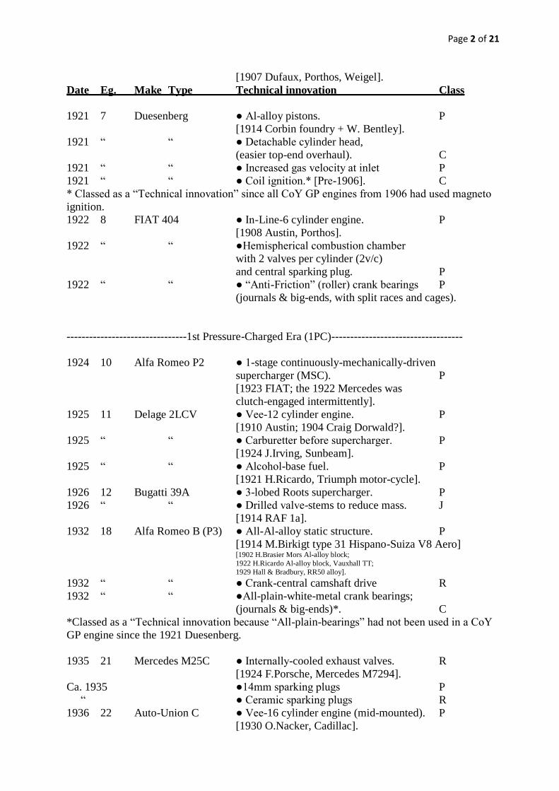
Page 1 of 21

ANALYSIS, 1906 – 2000 UPDATE: Part 1.

Technical Innovations in CoY Grand Prix engines.

The technical innovations in this 78-racing-year period are listed below. They are classified as

principally for Performance improvement (P) or for increase in Reliability (R), some-times for

both jointly (J) and sometimes for Reduced Cost (C). The date given is that when the

innovation was first incorporated into a Grand Prix “Car-of -the Year” (CoY), whose Example

should be consulted for full details. When the innovation had been pioneered elsewhere the

relevant date is given in square brackets [ ] with the name of the originator, if known (it is

recognised that “firsts” can be a very specialist subject, often harking back to some very ob-

scure cases, and the author begs the indulgence of those who may have done deeper research).

Of course, not all the technical innovations were accumulated in later engines, possibly

because they were superseded, possibly because their cost was disproportionate to their benefit,

possibly for simple conservatism or perhaps because they were banned by the regulatory

authorities.

In some cases, marked*, a “Technical innovation” is listed although it was the re-use of a

much earlier application because a considerable time gap of non-use separated them. The 1st

use may have been too far ahead of the technology available.

Date Eg. Make Type Technical innovation Class

--------------------------------1st Naturally-Aspirated Era (1NA).--------------------------------

1907 2 FIAT ● Overhead, opposed, inclined valves,

push-rod operated (PROHV). P

1912 4 Peugeot L76 ● Higher Piston Speed (MPS). P

[1907 M.Sizaire, Sizaire & Naudin].

1912 “ “ ● Double Overhead Camshafts (DOHC)

operating 4 opposed, inclined valves

per cylinder (4v/c). P

1912 “ “ ● Main bearings each side of a crank throw. R

1912 “ “ ● Pressure lubrication of all crank bearings. R

[1901 F. Lanchester].

1912 “ “ ● Valve opening overlap (OL). P

[1903 P.Riley].

1913 5 Peugeot L56 ● Counter-balanced crank. R

1913 “ ● Double valve springs J

1913 “ “ ● “Anti-Friction” (ball) main bearings. P

1913 “ “ ● “Dry” sump. R

1914 6 Mercedes M93654 ● Fabricated block & head to reduce weight. P

[1912 P. Daimler, Mercedes DF80 aero engine].

1914 “ “ ●Austenitic steel exhaust valves. R

[1914 Krupp].

1914 “ “ ● 3 Sparking plugs per cylinder . J

1914-1918 WW1--------------------------------------------------------------------------------------

1921 7 Duesenberg ● In-Line-8 cylinder engine. P

Page 2 of 21

[1907 Dufaux, Porthos, Weigel].

Date Eg. Make Type Technical innovation Class

1921 7 Duesenberg ● Al-alloy pistons. P

[1914 Corbin foundry + W. Bentley].

1921 “ “ ● Detachable cylinder head,

(easier top-end overhaul). C

1921 “ “ ● Increased gas velocity at inlet P

1921 “ “ ● Coil ignition.* [Pre-1906]. C

* Classed as a “Technical innovation” since all CoY GP engines from 1906 had used magneto

ignition.

1922 8 FIAT 404 ● In-Line-6 cylinder engine. P

[1908 Austin, Porthos].

1922 “ “ ●Hemispherical combustion chamber

with 2 valves per cylinder (2v/c)

and central sparking plug. P

1922 “ “ ● “Anti-Friction” (roller) crank bearings P

(journals & big-ends, with split races and cages).

--------------------------------1st Pressure-Charged Era (1PC)-----------------------------------

1924 10 Alfa Romeo P2 ● 1-stage continuously-mechanically-driven

supercharger (MSC). P

[1923 FIAT; the 1922 Mercedes was

clutch-engaged intermittently].

1925 11 Delage 2LCV ● Vee-12 cylinder engine. P

[1910 Austin; 1904 Craig Dorwald?].

1925 “ “ ● Carburetter before supercharger. P

[1924 J.Irving, Sunbeam].

1925 “ “ ● Alcohol-base fuel. P

[1921 H.Ricardo, Triumph motor-cycle].

1926 12 Bugatti 39A ● 3-lobed Roots supercharger. P

1926 “ “ ● Drilled valve-stems to reduce mass. J

[1914 RAF 1a].

1932 18 Alfa Romeo B (P3) ● All-Al-alloy static structure. P

[1914 M.Birkigt type 31 Hispano-Suiza V8 Aero] [1902 H.Brasier Mors Al-alloy block;

1922 H.Ricardo Al-alloy block, Vauxhall TT;

1929 Hall & Bradbury, RR50 alloy].

1932 “ “ ● Crank-central camshaft drive R

1932 “ “ ●All-plain-white-metal crank bearings;

(journals & big-ends)*. C

*Classed as a “Technical innovation because “All-plain-bearings” had not been used in a CoY

GP engine since the 1921 Duesenberg.

1935 21 Mercedes M25C ● Internally-cooled exhaust valves. R

[1924 F.Porsche, Mercedes M7294].

Ca. 1935 ●14mm sparking plugs P

“ ● Ceramic sparking plugs R

1936 22 Auto-Union C ● Vee-16 cylinder engine (mid-mounted). P

[1930 O.Nacker, Cadillac].

Page 3 of 21

Date Eg. Make Type Technical innovation Class

1936 22 Auto-Union C ● Copper-Lead plain main journal bearings. R

[1923 Allison].

1936 “ “ ● Oil cooler. R

1936 “ “ ● Hirth-system built-up crank. R

1937 23 Mercedes M125 ● Main bearing caps with cross-bolts. R

[1921 A.Rowledge, Rolls-Royce Condor].

1939 24 Mercedes M163 ● 2-stage mechanically-driven supercharger. P

1939-1945 WW2------------------------------------------------------------------------------------

1948 26 Alfa Romeo 158 ● Screwed-in wet cylinder liners. R

[1938 Alfa Romeo 158].

1948 “ “ ● Needle-roller big-end bearings

in split races. R

[1939 Alfa Romeo 158].

1949 27 Ferrari 125GPC/49 ● Bore(B)/Stroke(S) ratio above 1*. P

[The 1939 Maserati 4CL Voiturette,

IL4 4v/c, was 78mm/78mm = 1.

The 1924 Moto-Guzzi, 1 cyl. 4v/c,

500cc motor-cycle was 88/82 = 1.073].

1948 “ “ ● “Thinwall” lead-bronze-indium bearings,

journals & big-ends. J

[1930 Hopkins & Palm].

1949 “ “ ● Hairpin valve springs. R

[1925 Sunbeam motor-cycle].

*Classed as a “Technical innovation” because no CoY GP engine since 1907 had B/S>1.

-----------------------------------2nd Naturally-Aspirated Era (2NA)----------------------------

1952 30 Ferrari 500 ● Individual,tuned, inlet & exhaust systems. P

[1922 H.Miller, Miller 183cid; 1935 F.Dixon, Riley].

1952 “ “ ● 2 Sparking plugs per cylinder*. J

[1951 Ferrari 375 - not counting aero engines

since 1912, where used mainly for reliability].

*Classed as a “Technical innovation” because all CoY GP engines from 1920 onwards had

only 1 plug per cylinder.

1953 31 Ferrari 500 ● 2-choke/1 float chamber per cylinder pair

straight-through carburetters. P

[1914 Claudel (702)].

1954 32 Mercedes M196 ● Inclined engine (to reduce frontal area

& lower Centre of Gravity). P

[1952 Cummins Indy Diesel].

1954 “ “ ● Crank-central power offtake. R

[1948 E.Richter?, BRM].

1954 “ “ ● Direct into-cylinder fuel injection. P

[used previously for Diesel engines and

Daimler-Benz aero engines].

Page 4 of 21

Date Eg. Make Type Technical innovation Class

1954 32 Mercedes M196 ● Mechanically-closed (“desmodromic”)

poppet valves (DVRS). J

[1914 A.Michelat, Delage].

ca. 1955 ● 10mm sparking plug P

1956 34 Ferrari-Lancia D50 ● Vee-8 cylinder engine. P

[1903 Ader].

1956 “ “ ● Chain drive to OHC. C

[1930 AJS motor-cycle].

1956 “ “ ● Megaphone exhausts. P

[1932 Rudge-Whitworth motor-cycle].

1957 35 Maserati 250F1 ● Nitro-methane fuel component. P

[1950s; US Dragsters].

1958D 36 Ferrari 246 ● Vee-6 cylinder engine. P

[1950 F.di Virgilio, Lancia].

1958D “ “ ● High-Octane petrol (rule obligation). P

[See Note 58].

1958C 37 Vanwall V254 ● Multi-layer cylinder sealing ring. R

1958C “ “ ● Axial swirl to inlet charge by port shape. P

[Pre-1914 K.Hesselman, Atlas by partial

port masking.

1948 H.Weslake, by shaped port].

1958C “ “ ● Squish of compressed charge. P

[1919 H Ricardo for side-valve engines.

1951 L Kusmicki, Norton, for OHV.

Also 1932 L Goossen, Miller 220cid].

1958C “ “ ● L-section piston compression ring. R

[1950 P.Dykes, BRM].

1958C “ “ ● Slipper piston. P

[1922 H.Ricardo, Vauxhall TT].

1958C “ “ ● Into-port timed fuel injection. P

[1948 S.Hilborn, Offenhauser, untimed.

1956 Lucas, JaguarXK120D, timed].

1958C “ “ ● Piston cooling by oil jets. J

1958C “ “ ● Na-cooled inlet valves. J

[1924 F.Porsche, Mercedes M218].

1959 38 Climax FPF ● Sintered tungsten crank weights. R

1959 “ “ ● Inverted-cup tappets around valve springs. P

[1910 FIAT S61. 1916 A. Morin Patent].

1962 41 BRM P56 ● Lucas transistorised ignition. P

1962 “ “ ● Lucas shuttle-metered fuel injection

into ports. P

[1956 Jaguar XK120D].

1962 “ “ ● Inverted-cup tappets above valve springs. R

1962 “ “ ●Low-oil-pressure crank drillings. R

1962 “ “ ● Sliding-plate throttle. P

[1935 F.Dixon, Riley].

Page 5 of 21

Date Eg. Make Type Technical innovation Class

1968 47 Cosworth DFV ● 4 valves per cylinder (4v/c)

with narrow angle between inclined valves

(narrow VIA) and flat-top piston*. P

1968 ‘‘ ‘‘ ● Designed “Barrel Turbulence”

(“Tumble Swirl”). P

[Both of above innovations:-

1966 K.Duckworth, Cosworth FVA].

1968 ‘‘ ‘‘ ● Fuel cooled by circulation around inlet

manifold. P

1968 ‘‘ ‘‘ ● Reduced piston-ring Width/Stroke (w/S). J

1968 ‘‘ ‘‘ ● 7¼ inch driven-plate-diameter clutch. P

[Above 3 innovations:- 1967 K.Duckworth,

Cosworth DFV].

*Classed as a “Technical innovation” because it was combined with high compression ratio (R)

and squish, unlike eg. the 1919 IL4 Bentley 3L which had 4v/c and VIA = 30 degrees but low

R and “Negative Squish”.

1970? 49 Cosworth DFV ● Interference-fit double valve springs. R

[1964 Rolls-Royce FB60;

1965 Ford Indy 4-Cam].

1970 ‘‘ ‘‘ ● Camshaft-drive “Deflection-Absorber”. J

[1912 F.Royce, Rolls-Royce 40/50].

1970 ‘‘ ‘‘ ● Comprehensive oil-scavenging

and de-aereation. R

1974 53 Ferrari 312B ● Flat-12 cylinder engine. P

[1939 W. Ricart, Alfa Romeo 512].

1974 ‘‘ ‘‘ ● Updraught exhaust port. P

[1969 M.Forghieri, Ferrari 312B].

1980 60 Cosworth DFV ● High-strength Al-alloy casting. R

[1979 D.Campbell].

1980 ‘‘ ‘‘ ● Al-alloy Nikasil-coated cylinder liners. J

[1979 Cosworth DFV].

--------------------------------------2nd Pressure-Charged Era (2PC)----------------------------

1982 63 Ferrari 126C2 ● TurboCharging (TC). P

[For road-racing:- 1969 BMW 2002].

1982 ‘‘ ‘‘ ● Pistons oil-cooled by internal gallery R

[ca 1979 Renault & Mahle].

1982 ‘‘ ‘‘ ● Compressor-engine intercooling. J

[1927 F.Lockhart, Miller 91cid Special].

1982 ‘‘ ‘‘ ● Electronic + mechanical

Engine Management System (EMS). P

Page 6 of 21

1983 64 BMW M12/13 ● Toluene-base fuel obeying regulations

in specified CFR engine tests. P

Date Eg. Make Type Technical innovation Class

1984 66 Porsche PO1 ● Compound valve inclination. P

[1918 A.Elliot, Rolls-Royce Condor].

1984 ‘‘ ‘‘ ● All-Electronic EMS. J

1984 ‘‘ ‘‘ ●Water-sprayed intercoolers. P

1988 71 Honda RA168E ● 5½ inch driven plate-diameter

carbon-carbon clutch. P

[1987 M.Tilton, Lotus-Honda].

1988 ‘‘ ‘‘ ● IHI Ceramic TC turbine wheels

and ball-bearings. J

-------------------------------------3rd Normally-Aspirated Era (3NA)---------------------------

1989 72 Honda RA109E ● Vee-10 cylinder engine. P

[In parallel with Renault].

1989 ‘‘ ‘‘ ● Ti-alloy for all valves. P

[1983 Honda RS750 motor-cycle].

1989 ‘‘ ‘‘ ● Piston-rings run above flutter frequency. J

1990 73 Honda RA100E ● Pneumatic Valve Return System (PVRS). P

[1984 J-P. Boudy, Renault].

1991 74 Honda RA121E/B ● Variable-length inlet system (VIS). P

[1955 Mercedes-Benz experimental 300SLR].

1992 75 Renault RS4 ● Semi-automatic gearbox with

electronic engine control. J

[1989 J.Barnard, Ferrari].

1992 ‘‘ ‘‘ ● Traction control. P

1993 76 Renault RS5 ● Overhead fuel injector rail. P

1993 ‘‘ ‘‘ ● Drive-by-Wire (DBW). J

[1992 Honda RA122E/B, (SO20)].

1994D 77 Cosworth Z-R ● Forged Mg-alloy pistons. P

1994D ‘‘ ‘‘ ● Port-mounted barrel throttles. P

1994C 78 Renault RS6 ● Diamond-like-carbon (DLC)

anti-friction surface treatment. J

1996 80 Renault RS8 ● B/S >2. P

1998 82 Ilmor FO110G ● Camshaft-drive pendulum damper.

[1987 M. Illien, Chevrolet 265].

1998 ‘‘ ‘‘ ● Be/Al-alloy pistons. P

1998 ‘‘ ‘‘ ● Step-reduction in engine weight. P

[1996 J.Judd, Yamaha-Judd OX11A].

Page 7 of 21

1999D 83 Ilmor FO110H ● Be/Al-alloy cylinder liners. P

2000 85 Ferrari 049 ● V90degree 10-cylinder engine. P

2000 ‘‘ ‘‘ ● Bore/Piston Height (B/PH) >2 P

[Achieved at least by 1996 in Mugen MF301

and Yamaha-Judd OX11A of that year].

Throughout the 1906 - 2000 review period, although dates for specific applications cannot be

assigned to the advances made (apart from those mentioned above), there were steady general

developments in 5 major areas:-

● Higher Octane fuel (see Notes 23, 58-2 and 90);

● Reduced viscosity oil with higher surface protection

(changing from vegetable to mineral to synthetic);

● Higher Fatigue-Strength/Density materials from new alloys and new processes

(especially for pistons, see Note 14, and for exhaust valves, see Note 17);

● Improved plain bearings (see Note 18);

● Improved surface finishes to raise fatigue life

(Nitriding, shot-peening).

Late-period improvements also not attributable to particular Egs were:-

● Anti-friction coatings on cylinder liners and piston skirts (see Note 103);

● Ceramic heat-insulation coatings for exhaust valves and piston crowns;

● Crankshaft oil supply by end feed

[1944 Rolls-Royce Merlin Mk 100 series].

While not actually an engine improvement as such, another significant innovation was:-

● Two-way pit-car radio and multiple in-car sensors with telemetry to pits which enabled

specialists there to advise the driver on engine settings to optimise performance and

reliability via in-car controls.

Page 8 of 21

ANALYSIS, 1906 – 2000 UPDATE: Part 2.

Aero - Thermo - Mechanical Factor Developments.

(Refer to Appendix 1 for details of the engines powering the chosen

Grand Prix “Car-of-the-Year” (CoY))

During the 78 racing years covered in this review many attempts have been made to produce

more-or-less simple formulae based on piston engine geometry to predict the power which

would be obtained from a new design. The list of 122 technical innovations over the same

period given in Part 1 makes such prediction an impossible task, except for narrowly-drawn

classes of engines over very limited time periods, because human ingenuity would always

produce something during continuing development which was not allowed for in the historic

formula.

Some particularly significant examples of this statement are as follows (quoting the CoY in

which the innovation appeared, although it may have been pioneered earlier as explained in

Part 1):-

● the realisation that much higher piston speeds (MPS) were tolerable

(Eg 4 1912 Ernest Henri, Peugeot L76);

● the realisation that an engine could have too large an (Inlet Valve Area/ Piston Area)

(IVA/PA) ratio for good combustion

(Eg 7 1921 Frederick Duesenberg);

● the harnessing of pressure waves in inlet and exhaust systems to improve breathing

(Eg 30 1952 Aurelio Lampredi, Ferrari 500);

● the intentional creation of “Barrel Turbulence” (“Tumble Swirl”) in the cylinder

to improve combustion

(Eg 47 1968 Keith Duckworth, Cosworth DFV);

● the application of pneumatic springs to return valves to their seats (PVRS)

(Eg 73 1990 Honda);

● the application of “Diamond-Like Carbon” (DLC) coating to valve-gear rubbing surfaces

to reduce friction

(Eg 78C 1994 Renault).

In considering this impossibility of finding a formula to generalise piston engine perform-

ance, there is also the rule-related fact that the racing distance and so the life required from an

engine per event decreased steadily from the early years (but recently, post the review period,

by rule the engine life mandated without overhaul - except with a severe penalty - has first been doubled and then increased to four events!). Obviously the life required affected the

stresses tolerable and therefore the attainable Peak Power/Weight (PP/W) ratio. Combined

with this - in the opposite direction, however - was the time/technology increase in Load

Factor (= Average Power used/Peak Power) from about 0.4 to well over 0.6 as cornering speeds

rose with better road surfaces, improved suspension systems, plus better tyres and the

introduction of aerodynamic downforce. To complicate the latter two developments, rules

were established, and frequently altered, to limit their effects. Nothing short of a detailed

stress analysis against available material properties - which were also time/technology-related

(and since 2000 rule-related) - could evaluate such effects on PP/W.

Another point to be made about a study of Grand Prix engine development over these 78

racing years and 85 examples is that the variety of design and development techniques used

means that history cannot produce a smooth progression of performance, even after allowing as

well as possible for the various competition rules imposed by the governing authorities (as

listed in the Sporting Limits Table 1).

Page 9 of 21

Again, the “Car-of- the-Year” may have had the best engine or merely an adequate one, since

the final result comes from a mixture of many major elements :- engine; chassis; tyres; driver;

mechanics; money; management - and luck!

Inconsistency of performance measurement between manufacturers is a further cause of

scatter in the data (described for particular examples in Notes 5, 6 and 72).

Having entered all these caveats, so that the author has tried to prepare the reader for a “broad

brush” approach to the trends of the data, this will now be considered for the improvements in

Breathing, Burning and Turning, where the efficiency of each factor is given by:-

● Breathing = Volumetric Efficiency (EV);

●Burning = Combustion Efficiency (EC);

●Turning = Mechanical Efficiency (EM).

Sufficient reliability to go on doing these activities for the racing distance can be assumed for

the engine of the “Car-of-the-Year”.

The combined Efficiency function =[EV x EC x EM]

In the General Review and in detail in Note 10 the relation is given:-

Brake Mean Effective Pressure, with Fuel/Air mixture close to Stoichiometric,

= BMEP = 38 x MDR x ASE x [EV x EC x EM] Bar @ STP ambient conditions

(recapitulating that MDR = Manifold Density Ratio relative to ambient conditions,

calculated as described in Note 10B and assuming MDR = 1 for Natural Aspiration (NA);

and

ASE = Air Standard Efficiency

= 1 - 1/(R)0.4

where R = compression Ratio).

Therefore the different designs over the review period can be brought to a common basis for

comparison of efficiencies by taking out the fuel and rule variations affecting MDR and R (as

listed in ‘The Sporting Limits’ Table 1 and Appendix 2) by finding:-

BMEP = 38 x [EV x EC x EM] Bar.

MDR x ASE

To provide a recognisable number this equation is “normalised” to a compression ratio of

R = 12 for which ASE = 0.63 so that it becomes:-

BMEP x ASE @ R = 12 = 38 x 0.63 x [EV x EC x EM] Bar.

MDR ASE

ASE @ R = 12 is defined as RA and is given for each example on Row 77 in Appx. 1.

ASE

One other adjusting factor, AA, is brought in as a divisor to allow where appropriate for the

higher power possible on alcohol fuel when Naturally Aspirated, due to its cooling of the inlet

Page 10 of 21

charge by evaporation before entering the cylinder ( offsetting the port and valve heat input),

using AA = 1.12 as explained in the Glossary of Appendix 1 and shown on Row 43. The

adjustment is, in effect, to reduce EV down to the level possible on petrol fuel. This is not used

where the engine was Mechanically Supercharged (MSC) with alcohol fuel introduced before

the supercharger because the cooling effect is then calculated in finding MDR.

BMEP x RA is defined as BMPA and given on Row 79 of Appendix 1, and then

AA

BMPA = 24* x [EV x EC x EM] Adjusted Bar. Shown at Row 80 in Appendix 1.

MDR

June 2019. ECOM = [EV x EC x EM] % has been given at Row 132. This is plotted for the

CoY examples v. Date on Fig. A1 below.

______________________________

* Rounding up from 38 x 0.63 =23.94.

The key in Overview of Performance UPDATE applies to all Figures.

Discussion of trend of ECOM

Fig. A1 shows broadly 6 stages in the development of the efficiency product:-

[EV x EC x EM] % :-

1. rising from about 30% to about 47% over the 1st Naturally-Aspirated era (1NA) 1906-1923

as designers felt their way to better EC while EV was limited by using inlet systems which may

be described as “Tortuous”, with FIAT discovering in 1922 that reducing Inlet Valve

Area/Piston Area (IVA/PA), from the 0.5-plus value of pre-WW1 using 4 valves per cylinder

(4v/c) over-lapping the bore producing “Negative Squish”, to less-than-0.4, with 2v/c in a

compact hemispherical chamber, could provide an improved product of (EV x EC);

Page 11 of 21

2. holding an average around 43% while Mechanically-Supercharged (MSC) up to 1951 during

the 1st Pressure-Charged era (1PC), the pressurised inlet manifolds still being “Tortuous”. This

value of ECOM reflected a drop of EM because of the net power subtraction needed to drive

the (invariable) Roots-type superchargers (net because some of the shaft power was recovered

pneumatically on the inlet stroke). Ever-increasing alcohol-rich fuel mixtures to cool the

compressed charge were the order of the era as boost pressures increased;

3. the 2nd NA era up to 1967, when inlet and exhaust systems were made “Individual &

Tuned” to raise EV, covering ECOM of 47% to 50%

4. the advent in 1968 of Keith Duckworth’s architecture in the Cosworth DFV (introduced

originally in 1966 in his FVA F2 type). This reverted to 4v/c but at a narrower valve included

angle (VIA) - 320- than used previously, giving a reasonable combustion chamber Surface

Area/Volume ratio with adequate IVA/PA, with a flat piston crown despite a high compression

ratio giving a more efficient combustion space without a hump and a lighter reciprocating

assembly, and a sparking plug in the optimum central position. The fundamental plus of the

Duckworth design was then the all-important non-orthogonal port shape relative to the valve-

head at a downdraught angle which together promoted deliberate “Barrel Turbulence” (or

“Tumble Swirl”, see Notes 26 and 80). An ECOM around 55% over 1968-1982 was the result

as the product (EV x EC) was raised and then maintained while Mean Piston Speed at Peak

Power (MPSP) was increased steadily, which will be discussed below.

The success of the new approach to top-end architecture can be appreciated by comparing

Duckworth’s FVA unit (first run in 1966) with Coventry Climax’s last racing engine. Climax in

late 1963, wishing to raise the power available for the final year of the 1½ litre formula above

that from their FWMV 8-cylinder engine (then just under 200 HP) set to work on the FWMW

16-cylinder design. They hoped for 240-250 HP but by the end of 1965 had obtained from it

only 209 HP, =140 HP/L (34). Six months later Cosworth introduced the much cheaper FVA

1.6L engine giving 222 HP, =139 HP/L, (583) from only 4 cylinders. This was 38% better in

specific power than Climax had achieved with their 1.5L 4-cylinder (see Note 79). The superior performance was achieved partly from 15% higher BMEP and partly 16% higher MPS possible

with the lighter flat-top pistons.

The FVA top-end (with an 80 smaller VIA) became the heart of the 3L DFV Grand Prix

engine in mid-1967 for the new post-1965 formula and with steady improvement established

itself as the engine to beat until 1983. It powered 154 classic GP wins, 65% of the possible,

against competition from 10 other manufactures, half of which had greater resources than

Cosworth (see Note 75). Only the Turbo-charged engines displaced it and its DFY

improvement eventually (see Eg. 47 The Unique Cosworth Story).

The Cosworth DFV undoubtedly was the “Racing Engine of the Century”.

Its top-end architecture became the norm for all racing engines in a very short time and then

was adopted for even quite cheap production units;

5. Turbo-Charged (TC) engines in the 2nd PC era, 1983-1988, with an average around 65%

improving on the best NA engines in ECOM by having the same “Individual & Tuned” inlet

and exhaust systems but with a lower (better) combustion chamber Surface Area/Volume ratio

from lower compression ratio plus the “pneumatic” advantage from inlet charge pressure

exceeding exhaust back pressure without mechanical power deduction, and also benefitting

from lower friction losses because MPS was restricted to provide an adequate piston life (see

below), both of these factors raising EM;

Page 12 of 21

6. In the 3rd NA era from 1988 a similar level of ECOM to 2NA at first, rising to 60%. Higher

Peak Power RPM (NP) created increased friction and pumping losses (see Note 99), but this

was offset by efforts to reduce friction. A Cosworth paper by Simon Corbyn (1069) described

how EM of their Grand Prix engines was improved over 1999-2006 by:-

● reducing bearing areas;

● reducing piston ring tension and using improved Mo ring coatings;

● reducing piston mass for a given bore;

● applying DLC coating to piston skirts (as well as to the valve gear);

● reducing oil viscosity and volume.

Across the 78 racing years review the ECOM figures compare as follows:-

1906 2000

Engine Eg1 Eg85

Renault AK Ferrari 049

BMPA ABar 7.65 13.57 x1.77

MDR

Suggested [EV x EC x EM] 0.65 x 0.6 x 0.81 1.31 x 0.7 x 0.62 2 x 1.16 x 0.76

ECOM (rounded) =32% =57%

Clearly the improvement in Breathing (for which there is supporting data) has been the most

important efficiency development - the Combustion change suggested is notional - while

engineers have struggled to avoid losing too much Mechanical Efficiency as RPM and Mean

Piston Speeds were increased very greatly (as described below).

Limited data on 2014-2018

The 3PC (TC) Era beginning in 2014 is to the Hybrid Formula described briefly in Overview

of Performance UPDATE. Generally these V6 1.6L units are very similar to the 2PC (TC)

V6 1.5L engines. With the maximum fuel-flow-rate limit of 100 Kg/hour at 10,500 RPM it

was not necessary to set a TC IVP limit, as had been done in the last 2 years of the 2PC (TC)

era. An estimate of the maximum IVP which could be used is given on P.18, the level being

about 2 ATA.

Mercedes have been CoY in all 5 years, 2014-2018, of the Hybrid Formula so far. Some data

on their internal performance has been released officially – see Note 129 and columns DL

Extra 2 and DM Extra 3 in Appendix 1. Illustrations of the 2014 Mercedes PU106A are shown

in Appendix PA2 at Figures PA2-7 and PA2-8. With some approximations, the 2014 and 2018

estimated values of ECOM have been shown on Fig.01. Bearing in mind the 26 years of

technical advance since the last TC CoY engine, particularly that the new engines have 500 Bar

Direct Fuel Injection to prepare the mixture in place of low pressure port injection, an ECOM

of 69% for 2014 was judged reasonable.

Since then, despite very limited development allowed by the FIA rules, there has been a

further large gain to 2018. The introduction of Turbulent Jet Ignition is one known improver of

EC (see Internet articles, especially by Mahle). Mahle also claimed it permitted up to 4 points

higher Compression Ratio (R); this has been assumed in the calculation of the 2018 ECOM,

using R = 16.. The Mercedes engine and chassis were, of course made in England; the engine in the former

Ilmor plant at Brixworth; the chassis in the ex-Brawn ex-Honda ex-BAR plant at Brackley.

Page 13 of 21

Mean Inlet Gas Velocity at Peak Power (MGVP)

Part of the means by which BMPA/MDR was increased was by obtaining an optimum value

of Mean Gas Velocity at inlet to the cylinder and Fig. A2 shows this parameter (which is

calculated as incompressible flow related to the overall valve head diameter for convenience).

Note 34 discusses in detail the optimum value of MGVP when the highest product of (EV x

EC) is the target. In particular it explains that PC engines can operate best with a lower value

than NA because the mixture is heated and “mashed” in the compressor.

It is fairly clear that the optimum MGVP for NA has been found by experience to be around

72 m/s. This was first pointed out by the late Brian Lovell, (former MD of Weslake

Developments).

Addition of 2014-2018

The Formula for 2014-on, by limiting the fuel flow rate at 10,500 RPM and fixing the

dimensions automatically limits the piston speed and the MGVP. TC plus the Direct Fuel

Injection (DFI) at 500 Bar to prepare the mixture to a higher degree than any previous engine

(except possibly the 1954-1955 Mercedes-Benz M196. which also had DFI and MGVP about

45 m/s) relieves the need for high MGVP. There should be some gain from reduced inlet

system losses.

Continued on P. 14

Page 14 of 21

Crank Speed (NP) and Mean Piston Speed (MPSP) at Peak Power

To raise power it is necessary to increase Crank Speed provided that this does not cause an

equal or more than equal offsetting drop of (EV x EM) through increased pumping and friction

losses, as mentioned above. The variation of NP v. date is shown on Fig. A3.

The enormous change over 78 racing years and onward (2006 Cosworth CA/6 compared to the

1906 Renault AK was :-

19,250 RPM / 1,200 RPM = 16

was half due to the reduction of Stroke at limited MPSP. Fig. A4 below shows the

corresponding variation of MPSP as having been:-

25.5 m/s / 6 m/s = 4.3.

Much of this advance in MPSP occurred in the decade before WW1 when the example of

Maurice Sizaire’s Voiturettes of 1907-1908 led to a rise of :-

17 m/s / 6 m/s = 2.8,

even when using ferrous alloys for pistons (Note 35 discusses this in more detail).

Addition of 2014-2018

As discussed in Note 129 the engines to this Formula generally rev. past the peak power

speed (NP) of 10,500 RPM set by the flow-rate limit, up to 12,000 or perhaps in 2019 to 12,500

RPM. The Formula “Red line” limit of 15,000 RPM was an obvious dead letter from the start.

Continued on P. 15

Page 15 of 21

Although Al-alloys for the piston became available generally in WW1 their post-war use only

just preceded the application of Pressure-Charging, which placed greater pressures and

temperatures on that part, so that the average MPSP in the 1PC era did not rise significantly.

Post-WW2 alloys led to increases for NA engines but once again the adoption of Pressure-

Charging over 1983-1988 meant a comparative drop of MPSP despite the use of oil for cooling

the piston, by internal galleries and/or oil jets spraying under the crowns.

The last-mentioned feature became standard practice in the 3NA era as B/S ratio was raised.

With the “Flat- Top” piston introduced by the Duckworth reduced-VIA architecture and then

with pistons designed having Height ≈ Stroke (PH ≈ S)(see Note 13 Part 1), both being features

which reduced mass at a given Bore, a maximum MPSP with current materials around 25 m/s

has applied over the last two decades. This was with pistons limited to only about 3 hours life

at race rating or a few minutes at Qualification powers.

The subject of piston material development is elaborated in Note 14.

To minimise friction the “slipper” piston design pioneered by Ricardo in 1922 has become

standard in the last two decades, cutting away all non-bearing area of the skirt. However, strong

buttresses were still required to take pressure loads to the gudgeon pin so that this approach did

not reduce mass.

The figure of just over 25 m/s for the 2006 Cosworth is a remarkable tribute to detailed

design since life was required by a post-2005 rule to be 2 race events, ie practice, Qualification

and the race itself, and better Al-Be-alloys and Metal Matrix Composites were banned.

Mean Valve Speed (MVSP) and Bore Speed (BNP) at Peak Power

Note 13 Part III explains the significance of MVSP (Fig. A5 below) and its surrogate, at

various levels for specific classes of valve gear, of BNP (Fig. A6 below). As designers sought

more power from higher NP at ever-shorter Strokes, for a chosen number of cylinders, it was

necessary to solve the problem of increasing MVSP as valve lifts increased with larger valves

in bigger Bores, so as to keep control of valve motion.

Better cam design was the key to the doubling of MVSP after WW1 compared to pre-War but

then a plateau at 2.5 m/s occurred until the mid-‘60s except for the desmodromic valve gear of

the 1954-1955 Mercedes M196 (at 5 m/s) which was never used in any later CoY GP engine,

probably for cost reasons.

Continued on P. 16

Page 16 of 21

Interference-fitting double coil valve springs and better-quality vacuum-refined, shot-peened

wire then raised MVSP gradually for the universal Coil-spring Valve Return Systems (CVRS).

Inlet and exhaust valves in Ti-Alloy for NA engines helped from 1989 by reducing their

mass, stems also being drilled for the same reason. These improvements pushed MVSP up to 4

m/s.

The complete breakthrough came with the Pneumatic Valve Return System (PVRS) in 1990

for CoY, which had been patented by Jean-Pierre Boudy of Renault in 1984 (474). The

advantage of this system has been described in 3NA Part 1 at Egs. 72 and 73. By 2000 an

MVSP of 10 m/s was possible . Because late-period valve data is scarce the plot of BNP on Fig.

A6 below is also used here to show how valve gear speeds increased at a rapid rate from 1990

to 2003, all being DOHC 4 v/c.

The arrival of the “Diamond-like Carbon” (DLC) surface-finish process to reduce valve gear

friction below self-destructive temperature rise has been crucial to this increase.

There has also been a general re-adoption of finger-followers to take cam side-thrust instead

of the Henri-Morin-Woods inverted-cup tappets which were popular - but not universal - for

DOHC post-WW2.

Continued on P. 17.

Page 17 of 21

Note 15 gives much more detail of valve gear development.

It seems just possible from Fig. A6 that PVRS +DLC gear was approaching a limit at the

2006 level..

Maximum Piston Deceleration (MPD) at Peak Power

Another problem which had to be overcome as NP rose was the increase of MPD, shown on

Fig. A7, because of its effect on piston-ring flutter leading to combustion-gas blow-by and

thence to oil degradation and its loss overboard. Note 13 Part II describes this in detail.

In the mid-’50s this problem was solved by the invention by Prof. P. Dykes of the L-section

stepped-clearance compression ring (174).

Later a cheaper and less fragile cure was the manufacture of much thinner plain rings to meet

the limiting case:-

(Ring Axial Width) x MPD = constant..

The Cosworth DFV of 1967 (see Eg 47) was the first GP engine to use this solution.

Page 18 of 21

Engines post-1988 then began to be run at such a high RPM, as the problems mentioned

above were solved, that the rings did not have time to flutter - serendipity coming to the

engineers’ rescue! - and that was the case at the usual operating RPMs of the 3NA era.

However, it is necessary to keep crank speed before leaving the grid or in corners above the

critical ring vibration period (entering which has happened on occasion, see Note 13 Part III, to

the demise of the cars concerned).

D.S.Taulbut.

January 2009/June 2019.

On P. 19 is given an estimate of the IVP possible with the 2014-on Formula.

ADDENDUM

As a companion article to Fig. A1 showing ECOM an addition has been provided after P.19

entitled:-

SPARK IGNITION ENGINES. Progress in Thermal Efficiency.

Addendum P.20 provides the data of Brake Thermal Efficiency (BThE) for a wide variety of

engines (all those currently known to the author). Add. P.21 gives a chart of BThE v. Date.

This puts the remarkable values for the very-successful 2014-2018 Mercedes PU106 Hybrids in

perspective.

The outstanding Napier Lion VIIA point at BThE = 33% was the un-geared version which

powered the 2nd place Supermarine seaplane in the 1927 Schneider Trophy. It had the then-

unusually-high Compression Ratio of 10, running on a mixture of 75% Petrol + 25% Benzole +

the new additive of Tetra-Ethyl Lead (see Appendix 8, Illustrations for Appendix 8 and

Appendix 2 Table).

The point given for the Hewland experimental engine was a sleeve valve 1-cylinder 500 cc

design proposed as the basis for a Cosworth DFV 3 Litre replacement. The figure was for an

economy build. It was claimed that the racing version gave 72 BHP at a BThE of 29.5% (see

Wikipedia/Hewland). As a 6-cylinder 3 Litre main unit would have given probably less than

6 x 72 = 432 BHP and the DFV passed this level in 1971 it is assumed therefore that the

project was not continued.

The remarkable figure of BThE = 38% for the Teledyne Continental IOL 200 was

instrumental as the rear cruise engine in the non-stop round-the World exploit of the Rutan

Voyager in 1986 by Dick Rutan and Jeana Yeager. It had a Compression Ratio of 11.4 and

direct fuel injection, and was liquid-cooled (an innovation for a development of the usual

general aviation unit). It was funded as a military project for a reconnaissance drone.

Page 19 of 21

ADDENDUM on P.20

Page 20 of 21

SPARK IGNITION ENGINES. Progress in Thermal Efficiency.

Source: DST calcn. from numerous SFC sources

BThE - % %

Date Engine Inlet System @ Min. @ Peak

SFC Power

1910 Hispano-Suiza Alfonso XIII NA (T) T-Head 20 1914 Daimler Mercedes M93654 NA(T) OHV 23.5

1916 Hispano-Suiza Type 31 V8 Aero NA (T) OHV 26 1917 Rolls-Royce Eagle Series VIII NA (T) OHV 26.5 24.6

1917 Rolls-Royce Falcon Series III NA (T) OHV 24 23.3

1927 Napier LionMk VIIA NA(T) OHV 33.3

1931 Rolls-Royce R PC(MSC) OHV 23.8

1933 Riley Nine 2 carbs NA(T) OHV 28.7 23.6

1936 Rolls-Royce Phantom III NA(T) OHV 21.4

1938 Ford 30HP V8 Fe head NA(T) Side valve 21.3 19

1940 Pratt & Whitney R-2800 PC(MSC) OHV 28 1941 Pratt & Whitney R-2800 PC(MSC + TC) OHV 33 1944 Rolls-R0yce (Rover) Meteor NA(T) OHV 23.9

1948 Standard Vanguard NA(T) OHV 28.9 26.9

1948 Ford 30HP V8 Al-alloy head NA (T) Side valve 22.5 21.4

1948 Trojan NA(T) 2-Stroke 17.5 18.5

1950 Wright Turbo Compound PC(MSC +PRT) OHV 34 1951 Chrysler 5.4L V8 NA(T) OHV 28.3 1951 Lancia B20 NA(T) OHV 27.5 26.9

1960 Coventry Climax FPF Mk 2 NA(I) OHV 25.4

1962 AJS 7R 350 cc NA(I) OHV 25.7

1965 Coventry Climax FWMV Mk 6 NA(I) OHV 24

1975 Porsche 911 Carrera 3L NA(I) OHV 23.2

1975 Porsche 930 Turbo 3L PC(TC) OHV 19.9

1978 Ferrari 312B (T3) NA (I) OHV 23.8

1980 Hewland (Cosworth) 500cc Experimental NA(I) Sleeve valve 34 29.5

1986 Teledyne Continental IOL200 NA (I) OHV 38 1988 Honda RA168E PC(TC) OHV 30.6

1991 Mercedes-Benz M292 NA(I) OHV 30.6 29.6

1993 Yamaha 115 cc 13.6 Compression NA(T) 2-Stroke 21 1998 Ford 5.9L V8 NASCAR NA(T) OHV 32.6

2000 Ferrari 049 NA(I) OHV 26 2013 Cosworth CA2013 NA (I) OHV 30

2013 Toyota Lexus 3.5l Hybrid NA(I) OHV 38 2014 Mercedes PU106A Hybrid Incl. MGUK PC(TC) OHV 45

2014 '' '' '' Excl. MGUK 35

2018 Mercedes PU106E? Hybrid Incl. MGUK PC(TC) OHV 51.5

2018 '' '' '' Excl. MGUK 42

Page 21 of 21


Recommended