Analysis and design of a reinforced concrete deep beam with high thickness Vera Lúcia Oliveira Machado [email protected]Instituto Superior Técnico, Lisboa, Portugal March 2018 ABSTRACT The objective of this work concerns the analysis and design of an existing deep beam with a high thickness in reinforced concrete, according to the standards defined in the Eurocode. The structure is inserted in a hydroelectric plant in the Alentejo region of Portugal. The initial data is used to define the geometries and the loads based on the deep beam. The analysis began with a study of its environment, in order to determine the different actions and the loading for the ultimate limit state and the state of service. The analysis is followed by a study of numerical values known for simple cases in the elastic domain, then by an elastic analysis with finite element software IConc and finally with the strut and tie models. During the dimensioning step, the modeling of the structure was performed by the SAP2000 finite element software, in the order to evaluate the stresses resulting from the defined actions. This is followed by the perform of the safety checks and reinforcement calculations for the relevant ultimate and serviceability limit states, for the deep beam, but also for the columns. A detailed reinforcement plan could thus be created. Subsequently, thanks to the considered reinforcement arrangement, a verification at failure was performed by using the IConc software again and assuming an increase in the mobile loading. An optimization of the thickness of the web was also reflected, as well as the possibility of removing one of the columns, with the establishment of prestressing. Keywords: Deep beam, structural design, reinforced concrete, strut-and-tie, stresses field 1. INTRODUCTION This Master project focuses on the analysis and design of a reinforced concrete of a deep beam with high thickness. This deep beam is placed on two columns, with a span of about 9 m and restrained against a wall at one of these ends. The particularities of this deep beam are its consistent geometries, its vertical and horizontal loading. This one has already been built and is in operation now. However, it is not accessible to visitors and the provision of information is limited to available data [1], including the geometry of the deep beam studied, its loading and its operating limits at serviceability limit state. Figure 1 Sketch of the location of the deep beam in the central [1]
Transcript
Analysis and design of a reinforced concrete deep beam with high thickness
March 2018 ABSTRACT The objective of this work concerns the analysis and design of an existing deep beam with a high thickness in reinforced concrete, according to the standards defined in the Eurocode. The structure is inserted in a hydroelectric plant in the Alentejo region of Portugal. The initial data is used to define the geometries and the loads based on the deep beam. The analysis began with a study of its environment, in order to determine the different actions and the loading for the ultimate limit state and the state of service. The analysis is followed by a study of numerical values known for simple cases in the elastic domain, then by an elastic analysis with finite element software IConc and finally with the strut and tie models. During the dimensioning step, the modeling of the structure was performed by the SAP2000 finite element software, in the order to evaluate the stresses resulting from the defined actions. This is followed by the perform of the safety checks and reinforcement calculations for the relevant ultimate and serviceability limit states, for the deep beam, but also for the columns. A detailed reinforcement plan could thus be created. Subsequently, thanks to the considered reinforcement arrangement, a verification at failure was performed by using the IConc software again and assuming an increase in the mobile loading. An optimization of the thickness of the web was also reflected, as well as the possibility of removing one of the columns, with the establishment of prestressing. Keywords: Deep beam, structural design, reinforced concrete, strut-and-tie, stresses field 1. INTRODUCTION This Master project focuses on the analysis and design of a reinforced concrete of a deep beam with high thickness. This deep beam is placed on two columns, with a span of about 9 m and restrained against a wall at one of these ends. The particularities of this deep beam are its consistent geometries, its vertical and horizontal loading. This one has already been built and is in operation now. However, it is not accessible to visitors and the provision of information is limited to available data [1], including the geometry of the deep beam studied, its loading and its operating limits at serviceability limit state.
Figure 1 Sketch of the location of the deep beam in the central [1]
2. BACKGROUND The studied deep beam is inserted into the structure of a hydroelectric power station. This project consists of the construction of a new underground hydraulic circuit and an open-air power central. The entire facility consists of a buried structure with a depth of 52m, a width of 40m and a length of 80m. This structure consists of three independents structures of reinforced concrete, separated by expansion joints. The studied deep beam constitutes one of these parts. The dimensions of this one are one of these great particularities; 13.1 m high, 1.8 to 2.8 m wide and 25.5 m long. The consistent thickness of the deep beam is due of the global stability of the central, particularly for the risk of flotation due to the water just next to the structure. Thus, the whole structure needs to have a certain weight to counterbalance this risk.
2.1 GEOMETRIC DEFINITION The deep beam is supported by two columns, with a span of 9.4m and 11.5m. On the end, it is restrained at the extension of a retaining wall. On the other end, the deep beam is separated by an expansion joint with a structure almost identical to that studied. The first column has a section of 0.6m by 2.5m and the second, a section of 4m by 1m. Not knowing the exact height of the columns, a height of 9m was assigned to them. At the top of the deep beam, 13 prefabricated beams with a span of 20m and height of 1.6m and a cover slab are arranged. Above, we are outside the central. The deep beam has two layers; 1.8 m on the first 6.25 meters and 2.8m on the next 6.85. It is therefore a height of 13.1m and a total length of 25.5m. At almost half height, on the 1m of thickness’s difference, a mobile crane is arranged. On the other side, at the bottom of the deep beam, a slab is restrained. Above, embankment is arranged, and comes to rest on the outer face of the deep beam. For more detail, see the following figure.
2.2 MATERIALS AND SUSTAINABILITY The standards used to determine the different durability criteria for reinforced concrete are Eurocode 1992 1-1. Due to the importance of the work, both in its geometry and in its social utility, a period of life of 100 years is granted, i.e a structural class S6. The exposure class is defined like a XC1 (Concrete inside buildings with low air humidity). This results in a choice of minimal concrete cover, which should prevent corrosion of the steel and ensure an adequate transmission of adhesion forces. The determination of the covering is made according to the adhesion and environmental requirements:
Figure 2 Geometry of the studied structure
- Minimum concrete cover with respect to the adhesion requirements: Bar diameter: 40mm. - Minimum concrete cover with respect to environmental requirements: With exposure class XC4 and structural class S4, the minimum coating is 30 mm. Thus, the maximum value is 40 mm. A safety margin was not added. With an XC4 exposure class, the use of concrete with a strength class of C30 / 37 is recommended. It is also advisable to have a maximum cement water content of 0.65. 2.3 LOAD COMBINATIONS The different loads on the deep beam are primarily due to the cover of the central. This consists of the system of prefabricated beams and the cover slab, which rest on each end on a deep beam, including that of this study. Secondly, the crane placed on the eccentricity of 1 m wide, generates a vertical force. Thirdly, the embankment generates a horizontal load against the deep beam and a vertical load, due to the proper weight, at the bottom of the wall. It is also necessary to consider the weight of the structure. This one is modeled at half height, but on the two thicknesses of the deep beam.
In the plan
- 𝑔",$ = 281.3𝑘𝑁/𝑚+ 479.5𝑘𝑁/𝑚: Self-weight of the deep beam over the piles - 𝑔",5 = 1337kN/m: Support reaction along the bottom of the deep beam due to the weight of
the embankment, the slab and the overload acting above the slab bottom recessed at the bottom of the deep beam
- 𝐺",$ = 680𝑘𝑁: Support reaction acting as a concentrated load every 2 meters at the top of the deep beam. Reaction due to the weight of the beams, reinforced concrete cover and overload. There are 13 in all
- 𝑄 = 340𝑘𝑁: Punctual loads due to mobile crane acting along crane support. There are 8 charges of 340kN
Off the plan - 𝑝(𝑧)" = 6.21𝑘𝑁/𝑚A: Land earth pressure acting horizontally on the height of the deep beam
and 𝑃" the resulting
Figure 3 Load application
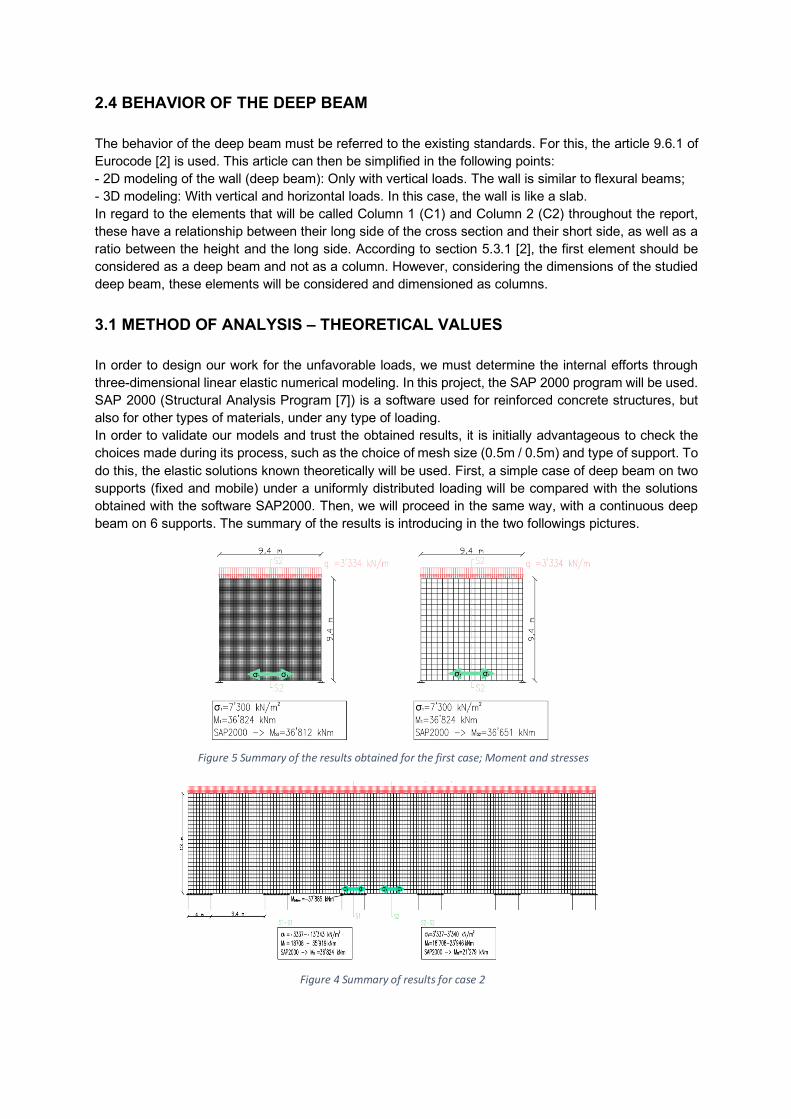
2.4 BEHAVIOR OF THE DEEP BEAM The behavior of the deep beam must be referred to the existing standards. For this, the article 9.6.1 of Eurocode [2] is used. This article can then be simplified in the following points: - 2D modeling of the wall (deep beam): Only with vertical loads. The wall is similar to flexural beams; - 3D modeling: With vertical and horizontal loads. In this case, the wall is like a slab. In regard to the elements that will be called Column 1 (C1) and Column 2 (C2) throughout the report, these have a relationship between their long side of the cross section and their short side, as well as a ratio between the height and the long side. According to section 5.3.1 [2], the first element should be considered as a deep beam and not as a column. However, considering the dimensions of the studied deep beam, these elements will be considered and dimensioned as columns. 3.1 METHOD OF ANALYSIS – THEORETICAL VALUES In order to design our work for the unfavorable loads, we must determine the internal efforts through three-dimensional linear elastic numerical modeling. In this project, the SAP 2000 program will be used. SAP 2000 (Structural Analysis Program [7]) is a software used for reinforced concrete structures, but also for other types of materials, under any type of loading. In order to validate our models and trust the obtained results, it is initially advantageous to check the choices made during its process, such as the choice of mesh size (0.5m / 0.5m) and type of support. To do this, the elastic solutions known theoretically will be used. First, a simple case of deep beam on two supports (fixed and mobile) under a uniformly distributed loading will be compared with the solutions obtained with the software SAP2000. Then, we will proceed in the same way, with a continuous deep beam on 6 supports. The summary of the results is introducing in the two followings pictures.
Figure 5 Summary of the results obtained for the first case; Moment and stresses
Figure 4 Summary of results for case 2
3.2 METHOD OF ANALYSIS – STRESS FIELD METHOD
Thus, the stress field method is a tool used to size and predict the behavior of a reinforced and prestressed concrete structure. It is based on the theory of plasticity, as the method of strut and tie. Thus, in order to correctly define the method of the stress fields, a parallel with the strut and tie method will be carried out. The finite element software IConc, available on the website "i-concrete.epfl.ch" makes possible the visualization of the stresses, thanks to an elastic analysis or an elastic-plastic analysis of the structure. An arched zone can be observed in tension in the lower part of the deep beam. Indeed, the efforts in the lower zone must partly go up and then move towards the supports. The working of the stresses will allow to help the determination and visualization of a model strut and tie close to reality. 3.3 METHOD OF ANALYSIS – STRUT AND TIE MODELS
The strut and tie model requires the balance between applied forces, reactions and elements in tension and compression. With manual setup and then with the linear-elastic analysis software Statik, equilibrium models are determined. This process is especially useful for allowing final gatherings of loads. However, for each model, the compressive and tensile forces make it possible to determine the width of the strut and the approximate reinforcement that would be necessary. In the figure 7, the model found is defined and the arched form with the ties can be observed.
4. NUMERICAL MODELING
Sap2000, a finite element software, would be used to determine the numerical model. The modeling that we considered for the deep beam is similar to that considered in the IConc software and during the analysis of the elastic behavior with the theoretically known value. So, the mesh used is cubes of 0.5m/0.5m/0.5m. For the supports, it was decided to let free to move in one direction (direction x) two of the three supports at the bottom of the columns. Indeed, it gave more important stresses. In 3D modeling, the extension of the slab, where the embankment is posed, and the wall of the extremity are also modeled, in order to allow the introduction of efforts. In both cases, it was decided to have mobile supports, blocked according to z and y for the wall of the extremity and according to z for the slab. The beams resting at the top of the slab are represented by mobile supports, blocked according to y. The results extracted from SAP2000 are the forces F11 [kN/m’], F22 [kN/m’], M11 [kNm/m’], M22 [kNm/m’], M12 [kNm/m’]. It is important to note some features, such as the extreme values that occur very locally to the first column. These values are taken with precaution because they influence the results of reinforcement in the bands and can overestimate the necessary reinforcement.
Figure 6 Relative stresses in IConc (Elastic analysis)
Figure 7 Strut and tie model choose
5. DESIGN OF THE DEEP BEAM The choice of bands was made according to the largest moments, but also in order to make easier the calculations and the future implementation. The Eurocode [2] is followed for determining the resistance of our sections to bending with axial force. By varying the distribution lines of the deformations between the boundary limit of the strain of the concrete and the reinforcing steel, it is possible to determine the resistance of the compressed zone and the reinforcement, based on respectively non-linear and elastic-plastic behavior. Thus, at each deformation state, a stress regime can be integrated in order to obtain the interaction between the bending moment and the normal force 𝑀D −𝑁D. The step of calculation of the reinforcement begin with a very rough approximation. It makes possible to determine the reinforcement necessary to satisfy limit of elasticity. In a second step, the reinforcement and its arrangement, as well as the moment and the normal force of dimensioning, are introduced in the spreadsheet provided by the Prof. Rui Vaz Rodrigues. This file has a macro that allows to find thanks to an integration according to the limits of the deformations of the Eurocode [2], to give the diagram of interaction between the normal moments and effort of rupture. Thus, it is checked at the ultimate limit state, if the determined reinforcement is reasonable. For all the elements, the maximum crack opening is limited to 0.3mm. Thanks also to the spreadsheet used for the ULS, crack opening will be determined. By varying the reinforcement arranged for the ultimate limit state, it is possible to make the opening be less than the requested limit. In most bands, the limitation to cracking is what determines the reinforcement. So, the necessary reinforcement was determined in order to check the resistance to the ULS, but also to the SLS cracking, in the vertical and horizontal direction of the deep beam. The values found were then modified to take into account the minimum reinforcement rate, but also arranged to facilitate the constructive layout and make it as regular as possible.
Figure 8 Schematization of the bands chosen horizontally and vertically
6. DESIGN OF THE COLUMN In this chapter, the design of the two columns has been done. The risk of buckling and the effect of the second order are considered and the confined concrete is also defined. This last graph shows that the addition of the moment of second order doesn’t influence the dimensioning of the reinforcement set up, even if it approaches a value where it is necessary to increase the diameter of reinforcement, for each column.
7. SHEAR REINFORCEMENT In the connection zone of column 1 with the web, the shear force will be checked in four sections: at the top of the column, on the deep beam at 2.8m, on the deep beam at 1.8m, in the slab. The SAP2000 software provides us with shear forces in two directions; 𝑉$A[𝑘𝑁/𝑚] et 𝑉IA[𝑘𝑁/𝑚]. In the following calculations, the value used is the result of these two efforts. 8. DETAILS In this chapter, constructive details are discussed, such as the cross reinforcement of the deep beam, the frame corners, the anchor length and the risk of overheating due to the volume of concrete during construction. 9. FAILURE OF THE DEEP BEAM In this part of the project, a study was carried out concerning the sensitive areas of the deep beam at a potential increase of the mobile load over time. To do this, the IConc software was used. Indeed, it has the advantage of having a visualization of the crushing of the concrete and the yielding of the bars. The load increase was up to 20 times the mobile load. After this step, the numerical results were no longer stable and physically consistent. In the curve of figure 62, a difference in rigidity can be observed between an increase of 15 to 20 times the crane effort.
Msd=0 kN.m
Nsd=82884 kN
70 000
72 000
74 000
76 000
78 000
80 000
82 000
84 000
86 000
-20 000 -10 000 0 10 000 20 000
𝑁R𝑑
[kN]
𝑀R𝑑 [kNm]
Interaction diagram 𝑁𝑒𝑑 − 𝑀𝑒𝑑
diam 20 diam 16
Msd=761 kN.m
Nsd=39400 kN
-30 000
-20 000
-10 000
0
10 000
20 000
30 000
40 000
50 000
60 000
-10 000 -5 000 0 5 000 10 000
𝑁R𝑑
[kN]
𝑀R𝑑 [kNm]
Interaction diagram 𝑁𝑒𝑑 − 𝑀𝑒𝑑
diam 40 diam 32
Figure 10 Interaction diagram Ned-Med with the second order effect for the first column
Figure 9 Interaction diagram Ned-Med with the second order effect, with a focus on the area of interest for the second
column
Figure 11 Representation of the failure with an increase of the crane effort
10. THICKNESS OPTIMIZATION After dimensioning and analyzing the behavior of the deep beam, an optimization of the thickness of the deep beam was studied. The thickness is substantial, but it ensures the stability of the central, as explained in sub-chapter 2.1 of this project. However, in order to find the best ratio between concrete thickness and the rate of reinforcement, a thickness optimization study is undertaken on a selected part of the deep beam. To start the optimization, a parallel with the strut and tie model is done. It is important to note that this approach is very subjective and that it only allows to have a first value of thickness to introduce. Indeed, the strut and tie model is based on the plastic theory and the direction of the strut is essential to check the resistance of the concrete. In the results obtained with the SAP2000 software modeling, the direction of the efforts is three-dimensional. It is possible to determine in which band the maximum compressive force is located. For the upper part of the deep beam, with a thickness of 1.8 m, it is on the CH-A-6 belt and for the part with 2.8 m of thickness it is on the CH-A-11. It should be noted that the efforts at the level of the slab have not been considered, as an optimization of the thickness at this level doesn’t make sense. The following minimum thicknesses are obtained:
Table 2 Result of the thickness for the critical band
Band 𝑡MNO[𝑚] 𝑡PQRRSTO[𝑚]
CH-A-06 0.77 0.8
CH-A-11 2.29 2.3
In order to know if this optimization is feasible, a new modeling on the SAP2000 software is carried out. With the new results, only the critical sections are checked. It was thus decided that a decrease of the thickness on the top of the deep beam of less than 0.8 m was not relevant, considering the increase of necessary reinforcement. However, a new iteration for the bottom of the deep beam has been carried out. As the mobile crane needs at least one meter to land, a thickness of 1.8m was used and checked. It is important to note that an optimization of the deep beam must be followed by a change of the sections of the columns, especially that of the first one. Indeed, it has a section of 2.5m / 0.6m, which causes an overshoot over the wall. This study is however not carried out, but just noted. 10.1 PRESTRESS In view of the substantial reinforcement placed in the tensile zone on the bottom of the deep beam, the idea of using prestressing cables is introduced. However, in order to go further in optimization reasoning, the need for the second column has also been questioned. Thus, the following study concerns a possible installation of prestressing cable at the bottom of the tie zone, while removing the central column. In the first place, it is necessary to determine the load that the cables need to accommodate for. By observing the main forces of the wall provided by the SAP2000 software, the same tensile vault is observable. (See figure 12) Thus, it is chosen to integrate from the horizontal tensile stresses on the mid-span the resulting tensile force, which is 40’800 kN. Cables type Y186057-15,7, with 19 strands (19T155) are chosen, with a set up by pre-tensioning and 11
Figure 12 Schematization of the main forces
prestressing cable are needed. Regarding their arrangement on the section of the deep beam of 1.8 m, it is necessary to consider that each cable has an outside diameter of 116 mm2 and that a minimum spacing of 100 mm between each cable is advised. Thus, it is chosen to have three layers of 3 cables and one layer of 2 cables, rectilinear just above the passive frame. In the following picture, the schematization of the disposition of the cable in the anchor zone and in the mid-span are shown. This gives a total force of 40.6 MN, or 3.7 MN per cable. However, it is necessary to consider losses due to friction and also losses due to time dependent; losses due to friction, creep of concrete, shrinkage of the concrete and relaxation of prestressing steel. A loss of 50 N/mm2 is found for long-term relaxation. Thus, the total of delayed effects is 157N/mm2, which is equivalent to a loss of 13.4% compared to the initial stress. Then, it is possible to define the force equivalent to an infinite time, which will be introduced into the modeling of the deep beam in SAP2000. A dimensioning of the main reinforcement in the entirety of the deep beam is carried out, in order to check the resistance of the different bands, as well as the cracking. 10.2 COMPARISON BETWEEN THE INITIAL STRUCTURE AND THE OPTIMIZED MODEL The comparison between the two models is done at the financial level and focusing only on the main frame (vertical and horizontal). In the optimized model, a reduction of the concrete, as well as a reduction of the horizontal reinforcement is observable. This last reduction is mainly due to the weaker need of the minimum reinforcement to remain the control of the cracking and the installation of the prestressing cables. On the other hand, an increase in the vertical reinforcement is visible. This is due first of all to the removal of the central column, which causes a recovery of the vertical force greater, to redirect to the columns at the end. The final price between the two models remains in the same price range.
Total Density [kg/m3] 155.2 293.1 + 88.9 22’130 153’000 156’005
However, for our study, given the amount of prestressing cables disposed and its implementation limit on the thickness of the deep beam, it was considered that it was not advisable to dispose more. In addition, the internal forces are considered acceptable in view of the order of magnitude similar to the initial model. In future work, it would be advantageous to conduct a study on the section of the first column in a way to be more adequate, because the column risk a bursting of the concrete. Also with the anchor heads and the consequent reinforcement above the column 1, the implementation is complicated. In addition, the column must take a big strut. So, the section of the column could be adapted to these requirements, for example, a larger section on the top of the column.
Figure 13 Schematization of the prestressing disposition
11. CONCLUSION This work studied the behavior of a deep beam with a high thickness, thanks to different methods of analysis, using the European norms. In the continuity of this project, it is possible to note other variants, but which come to consider the neighboring structures and the general stability of the central. The optimization of the section of the first column facing the section of the deep beam should also be studied but considering the architectural wishes of its disposition. It would also be possible to improve the disposition of prestressing, especially in the connection zone with the first column. These latest studies require a need for additional plant-wide information, which is only partially provided as part of this project. It could also have been considered to study in more detail, the establishment and the process of construction of the whole structure studied. BIBLIOGRAPHIC REFERENCE
[1] Documentation of the central’s operation: Oliveira C., Gama, V., Vaz Rodrigues, R., Santo A. Central do Reforço
de Potência do Escalão de Alqueva. Encontro Nacional de Betão Estrutural 2012; [2] NP EN 1992-1-1:2004, Eurocode 2: Design of concrete structures – Part 1-1: General rules and rules for building;
[3] US Army Corps of Engineers, Engineering and Design: Stability analysis of concrete structures, EM 1110-2-
2100, 1 December 2005; [4] KOSTIC Neven, « Topologie des champs de contraintes pour le dimensionnement des structures en béton
armé », Thèse n°4414 (2009), EPFL, Lausanne, 11 juin 2009
[5] Prof. Dr. MUTTONI Aurelio et Dr. FERNÁNDEZ RUIZ Miguel, « Champs de contraintes pour le béton structural », Article tracés n°05, 21 mars 2017
[6] Support documentation for Imesh and IConc software: Assistants personal powerpoints for constraint field
project [7] CSI Computers & Structures INC., CSI Analysis Reference Manual for SAP2000, ETABS, SAFE and CSiBridge,
ISO GEN062708M1 Rev.14 Berkeley, California, USA, July 2015
[8] Grekow, A., Isnard, V., Mrozowicz, Formulario del ingeniero (Formulaire de l’Ingénieur avec exposés de méthodes pratiques de calcul d’ouvrages de Génie civil), Urmo, S.A. de Ediciones, 1964.
[9] Renaud Favre, Jean-Paul Jaccoud, Olivier Burdet and Hazem Charif, Dimensionnement des structures en béton,
Aptitude au service et éléments de structures, Traité de Génie Civil de l’Ecole polytechnique fédérale de Lausanne, Volume 8, Presse polytechniques et universitaires romandes, 1997
[10] Norme suisse SN 505 262, SIA 262 : 2013 construction en béton, Société suisse des ingénieurs et des
architectes, 2013
[11] Prof. Dr Aurelio Muttoni, Dr Miguel Fernández Ruiz, Structures en béton, Ecole Polytechnique Féférale de Lausanne, Année académique 2014-2015
[12] NP EN 1990: 2002, Eurocodes - Basis of structural design
[13] Anton J. Schleiss et Henri Pougatsch, Les barrages du projet à la mise en service, Traité de Génie Civil de l’Ecole polytechnique fédérale de Lausanne, Volume 17, Presse polytechniques et universitaires romandes, 2011
[14] F. Leonhardt, E. Mönnig, Construções de concreto, Princípios básicos sobre a armação de estruturas de
concreto armado, Vol. 3, Editora Interciéncia LTDA, 1978 [15] J. Schlaich, K. Schäfer, M. Jennewein, Toward a consistent Design of Strucutural Concrete, Special Report,