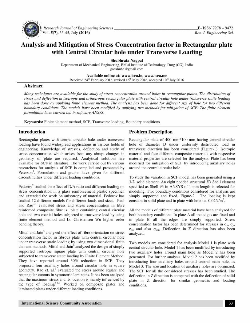
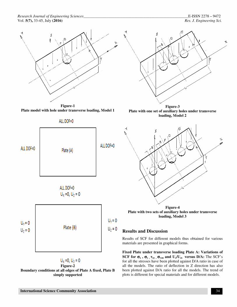
Research Journal of Engineering
Vol. 5(7), 33-45, July (2016)
International Science Community Association
Analysis and Mitigation of Stress Concentration factor in Rectangular plate
with Central Circular hole under Transverse Loading
Department of Mechanical Engineering,
AvailableReceived 24th February 2016, revised
Abstract
Many techniques are available for the study of stress concentration around holes in rectangular plates. The distribution of
stress and deflection in isotropic and orthotropic rectangular plate with central circular hole under transverse static loadi
has been done by applying finite element method. The analysis has been done for different size of hole for two different
boundary conditions. The models have been modified by applying two methods for mitigation of SCF. The finite element
formulation have carried out in software A
Keywords: Finite element method, SCF, Transverse loading, Boundary conditions.
Introduction
Rectangular plates with central circular hole under transverse
loading have found widespread applications in various fields of
engineering. Knowledge of stresses, deflection and study of
stress concentration which arises from any abrupt changes in
geometry of plate are required. Analytical solutions are
available for SCF in literature. The work carried out by various
researchers for analysis of SCF is compiled and presented by
Peterson1. Formulation and graphs have given for different
discontinuities under different loading conditions.
Fedorov2 studied the effect of D/A ratio and different loading on
stress concentration in a glass reinforcement plastic specimen
and extended the work on anisotropy of material.
studied 12 different models for different loads and sizes. Paul
and Rao3,4
evaluated stress and stress concentration in fibre
reinforced composite fibrous plate containing central circular
hole and two coaxial holes subjected to transverse load by using
finite element method and Lo Christensen Wu higher order
bending theory.
Mittal and Jain5 analyzed the effect of fibre orientation on stress
concentration factor in fibrous plate with central circular hole
under transverse static loading by using two dimensional finite
element methods. Mittal and Jain6 analyzed the design of simply
supported isotropic square plate with central circular hole
subjected to transverse static loading by Finite Element Method.
They have reported around 30% reduction in SCF. They
proposed four auxiliary holes around circular hole in square
geometry. Rao et. al.7 evaluated the stress around square
rectangular cutouts in symmetric laminates. It has been analyzed
that the maximum stress and its location is mainly influenced by
the type of loading8-12
. Worked on composite plates and
laminated plates under different loading conditions.
Engineering Sciences _________________________________________
Association
Analysis and Mitigation of Stress Concentration factor in Rectangular plate
with Central Circular hole under Transverse Loading
Shubhrata Nagpal Department of Mechanical Engineering, Bhilai Institute of Technology, Durg (CG), India
Available online at: www.isca.in, www.isca.me February 2016, revised 16th May 2016, accepted 10th July 2016
available for the study of stress concentration around holes in rectangular plates. The distribution of
stress and deflection in isotropic and orthotropic rectangular plate with central circular hole under transverse static loadi
g finite element method. The analysis has been done for different size of hole for two different
boundary conditions. The models have been modified by applying two methods for mitigation of SCF. The finite element
formulation have carried out in software ANSYS.
Finite element method, SCF, Transverse loading, Boundary conditions.
Rectangular plates with central circular hole under transverse
loading have found widespread applications in various fields of
engineering. Knowledge of stresses, deflection and study of
stress concentration which arises from any abrupt changes in
geometry of plate are required. Analytical solutions are
available for SCF in literature. The work carried out by various
or analysis of SCF is compiled and presented by
. Formulation and graphs have given for different
discontinuities under different loading conditions.
studied the effect of D/A ratio and different loading on
ss reinforcement plastic specimen
and extended the work on anisotropy of material. Fedorov has
studied 12 different models for different loads and sizes. Paul
evaluated stress and stress concentration in fibre
e containing central circular
hole and two coaxial holes subjected to transverse load by using
finite element method and Lo Christensen Wu higher order
orientation on stress
concentration factor in fibrous plate with central circular hole
under transverse static loading by using two dimensional finite
analyzed the design of simply
ntral circular hole
subjected to transverse static loading by Finite Element Method.
They have reported around 30% reduction in SCF. They
proposed four auxiliary holes around circular hole in square
evaluated the stress around square and
rectangular cutouts in symmetric laminates. It has been analyzed
that the maximum stress and its location is mainly influenced by
. Worked on composite plates and
laminated plates under different loading conditions.
Problem Description
Rectangular plate of 400 mm*100
hole of diameter D under uniformly distributed load in
transverse direction has been considered (Figure
material and four different composite materials with respective
material properties are selected for the analys
modified for mitigation of SCF by introducing auxiliary holes
around the central circular hole.
To study the variation in SCF model has been generated using a
3-D solid element. An eight nodded structural 3D Shell element
specified as Shell 93 in ANSYS of 1 mm length is selected for
modeling. Two boundary conditions considered for analysis are
simply supported and fixed, Figure
constant in solid plate and in plate with hole i.e. 0.02N/m
All the models of different plate material have been analyzed for
both boundary conditions. In plate A all the edges are fixed and
in plate B all the edges are simply supported. Stress
concentration factor has been determined for stresses in
σxy and also σvon. Deflection in Z direction has also been
analyzed.
Two models are considered for analysis Model 1 is plate with
central circular hole. Model 1 has been modified by introducing
two auxiliary holes around main hole as Model 2 has been
generated. For further analysis, Model 2 has been modified by
introducing four auxiliary holes around central main hole, as
Model 3. The size and location of auxiliary holes are optimized.
The SCF for all the considered stresses has been studied. The
deflection in Z direction is compared
plate in Z direction for similar geometric and loading
conditions.
______E- ISSN 2278 – 9472
Res. J. Engineering Sci.
33
Analysis and Mitigation of Stress Concentration factor in Rectangular plate
with Central Circular hole under Transverse Loading
Bhilai Institute of Technology, Durg (CG), India
available for the study of stress concentration around holes in rectangular plates. The distribution of
stress and deflection in isotropic and orthotropic rectangular plate with central circular hole under transverse static loading
g finite element method. The analysis has been done for different size of hole for two different
boundary conditions. The models have been modified by applying two methods for mitigation of SCF. The finite element
Rectangular plate of 400 mm*100 mm having central circular
hole of diameter D under uniformly distributed load in
transverse direction has been considered (Figure-1). Isotropic
material and four different composite materials with respective
selected for the analysis. Plate has been
mitigation of SCF by introducing auxiliary holes
To study the variation in SCF model has been generated using a
odded structural 3D Shell element
in ANSYS of 1 mm length is selected for
modeling. Two boundary conditions considered for analysis are
simply supported and fixed, Figure-2. The loading is kept
constant in solid plate and in plate with hole i.e. 0.02N/m2.
ent plate material have been analyzed for
both boundary conditions. In plate A all the edges are fixed and
in plate B all the edges are simply supported. Stress
concentration factor has been determined for stresses in σx, σy,
in Z direction has also been
Two models are considered for analysis Model 1 is plate with
central circular hole. Model 1 has been modified by introducing
two auxiliary holes around main hole as Model 2 has been
Model 2 has been modified by
introducing four auxiliary holes around central main hole, as
Model 3. The size and location of auxiliary holes are optimized.
The SCF for all the considered stresses has been studied. The
deflection in Z direction is compared with the deflection of solid
plate in Z direction for similar geometric and loading
Research Journal of Engineering Sciences______________________________________________________E-ISSN 2278 – 9472
Vol. 5(7), 33-45, July (2016) Res. J. Engineering Sci.
International Science Community Association 34
Figure-1
Plate model with hole under transverse loading, Model 1
Figure-2
Boundary conditions at all edges of Plate A fixed, Plate B
simply supported
Figure-3
Plate with one set of auxiliary holes under transverse
loading, Model 2
Figure-4
Plate with two sets of auxiliary holes under transverse
loading, Model 3
Results and Discussion
Results of SCF for different models thus obtained for various
materials are presented in graphical forms.
Fixed Plate under transverse loading Plate A: Variations of
SCF for σσσσx , σσσσy , τxy , σσσσvon and Uz/Uzs versus D/A: The SCF’s
for all the stresses have been plotted against D/A ratio in case of
all the models. The ratio of deflection in Z direction has also
been plotted against D/A ratio for all the models. The trend of
plots is different for special materials and for different models.
Research Journal of Engineering Sciences______________________________________________________E-ISSN 2278 – 9472
Vol. 5(7), 33-45, July (2016) Res. J. Engineering Sci.
International Science Community Association 35
Figure-5
SCF)x Vs D/A for fixed plate of all models
It has been noted that the effect of D/A ratio is prominent for
SCF of σx for all cases considered. It is observed from Figure-5,
that there is no reduction in SCF by providing auxiliary holes
along with the main hole. The trend of curves for Model 1 and
Model 3 are same. The SCF)x is more in case of Model 3 than
that for Model 1. The SCF)x is maximum in case of Model 2 for
higher D/A ratio. The SCF)x increased with D/A ratio for all the
materials.
Research Journal of Engineering Sciences______________________________________________________E-ISSN 2278 – 9472
Vol. 5(7), 33-45, July (2016) Res. J. Engineering Sci.
International Science Community Association 36
Figure-6
SCF for σy Vs D/A for fixed plate of all models
SCF)Y is almost constant for all the materials with respect to
D/A ratio. The magnitude of SCF)Y decreases as D/A ratio
increases for all the materials undertaken. From the above figure
it can be seen that the trend of curves are same for Model 2 and
Model 3. . SCF)Y is maximum for Model 3.
Research Journal of Engineering Sciences______________________________________________________E-ISSN 2278 – 9472
Vol. 5(7), 33-45, July (2016) Res. J. Engineering Sci.
International Science Community Association 37
Figure-7
SCF)xy Vs D/A for fixed plate of all models
The curves show downwards trend for all the materials as D/A
ratio increases. The curve is a straight line for all the materials
expect for e- glass/epoxy considering Model 1. The (SCF)XY is
maximum for Model 3 and minimum for Model 1.SCF for σxy
shows less influence of D/A ratios for all materials considered.
Research Journal of Engineering Sciences______________________________________________________E-ISSN 2278 – 9472
Vol. 5(7), 33-45, July (2016) Res. J. Engineering Sci.
International Science Community Association 38
Figure-8
SCF)von Vs D/A for fixed plate of all models
From the curves drawn it is conclude that SCF)von is almost
constant for all the materials as D/A ratio increases from 0.1 to
0.5 . SCF)von is maximum for Model 3 . For both Model 2 and 3
the trends of curves are downwards, which shows that the
SCF)von decreases as D/A ratio increases in modified models.
In boron/epoxy plate model the SCF)von for Model 2 is almost
same as in plate model with single circular hole and in case of
Model 3 the SCF)von decreases as we go for higher D/A ratio. In
all the other materials the trend of curves are same for Model 2
and Model 3.
The deflection in Z direction in Model 1 , Model 2 and Model 3
has been compared with the deflection in solid plate .
Research Journal of Engineering Sciences______________________________________________________E-ISSN 2278 – 9472
Vol. 5(7), 33-45, July (2016) Res. J. Engineering Sci.
International Science Community Association 39
Figure-9
UZ/UZS Vs D/A for fixed plate of all models
Deformation in plate in Z direction in solid plate and
deformation in modified model are compared. The curves are
plotted between ratio of these deflection and D/A ratio for all
the models. The influence of D/A ratio is substantial for ratios
of Uz/Uzs for all cases of materials.
The curves show that this deformation ratio decreases for
isotropic material and E - glass/ epoxy after introducing the
auxiliary holes around main hole. This reduction is more for
lower values of D/A ratio. The curves represents that this ratio is
almost constant for Model 2 and Model 3 for all D/A ratios.
For Boron/ Aluminium, Boron/Epoxy and Woven/Epoxy this
ratio increases as auxiliary holes are introduced. This shows that
by introducing auxiliary holes in a fixed plate of these materials
the deformation increases as compared to the solid plate of same
material and under same loading conditions for all D/A ratio.
Research Journal of Engineering Sciences______________________________________________________E-ISSN 2278 – 9472
Vol. 5(7), 33-45, July (2016) Res. J. Engineering Sci.
International Science Community Association 40
Simply supported plate under transverse loading, Plate B
Variations of SCF for σσσσx , σσσσy , τxy , σσσσvon and Uz/Uzs versus D/A
Figure-10
SCF)x Vs D/A for simply supported plate of all models
SCF for σx varies from 0.8 to 1.4 for all the cases. SCF
decreases as D/A ratio increases for all the materials except for
boron/epoxy. In boron/epoxy plate its magnitude increases
somewhat with D/A ratio.
For boron/aluminium the SCF is 0.8 for D/A ratio =0.1 which
decreases and is minimum, equal to 0.53 for D/A =0.5 for
Model 1. For Model 2 and 3, the (SCF)x is 1.12 for D/A=0.1
and decreases as D/A ratio increases . The trend of curve for
Model 2 and Model 3 is almost similar.
SCF)Y decreases with higher values of D/A ratio for all the
materials considered. For boron/ aluminium the (SCF)Y is
almost constant for all D/A ratio .SCF)Y is 3 for all D/A ratio
for Model 1 .It can be seen from the Figure-11 that the SCF)Y is
10.5 for D/A = 0.1 for Model 2 and reduces to 9.0 for D/A =
0.5.By studying the plot for Model 3 it can be deduced that the
value of SCF)Y decreases as D/A ratio increases . SCF)Y is
maximum for Model 3 and it is varying from 14.0 to 12.0 for
all D/A ratios.
Research Journal of Engineering Sciences______________________________________________________E-ISSN 2278 – 9472
Vol. 5(7), 33-45, July (2016) Res. J. Engineering Sci.
International Science Community Association 41
Figure-11
SCF)Y Vs D/A for simply supported plate of all models
Plate(B) Woven Epoxy
Model 1
Model 2
Model 3
Research Journal of Engineering Sciences______________________________________________________E-ISSN 2278 – 9472
Vol. 5(7), 33-45, July (2016) Res. J. Engineering Sci.
International Science Community Association 42
Figure-12
SCF)XY Vs D/A for simply supported plate of all models
SCF) XY
Research Journal of Engineering Sciences______________________________________________________E-ISSN 2278 – 9472
Vol. 5(7), 33-45, July (2016) Res. J. Engineering Sci.
International Science Community Association 43
Figure-13
SCF)VON Vs D/A for simply supported plate of all models
SCF)VON is between 0.5 to 2.0 for D/A=0.1 for all materials , as
we analyze the curves.SCF)VON is 2 , which is maximum for e-
glass/ epoxy and increases for Model 2 and Model 3. For Model
3 SCF)VON increases from 3.5 to 5.5.for all the material
considered SCF)VON is minimum for Model 1 , increases for
Model 2 and is maximum for Model 3.Curves are not following
any particular trend, as the trend is different for all the models.
SCF) VON
Research Journal of Engineering Sciences______________________________________________________E-ISSN 2278 – 9472
Vol. 5(7), 33-45, July (2016) Res. J. Engineering Sci.
International Science Community Association 44
Figure-14
UZ/UZS VS D/A for simply supported plate of all models
Deformation in plate in Z direction in solid plate and
deformation in modified model are compared. The curves are
plotted between ratio of these deflection and D/A ratio for all
the models.
For isotropic material UZ/UZS increases from 7.0 to 11 from
D/A=0.1 to 0.3 then decreases to 9.7 for D/A =0.5. UZ/UZS is
almost constant for boron/epoxy.
For boron/aluminium, boron/epoxy and woven/epoxy this ratio
increases as auxiliary holes are introduced. This shows that by
introducing auxiliary holes in a fixed plate of these materials the
deformation increases as compared to the solid plate of same
material and under same loading conditions for all D/A ratios.
Research Journal of Engineering Sciences______________________________________________________E-ISSN 2278 – 9472
Vol. 5(7), 33-45, July (2016) Res. J. Engineering Sci.
International Science Community Association 45
Conclusion
SCF)Y is almost constant for all the cases. By introducing
auxiliary holes in a fixed plate of these materials the
deformation increases as compared to the solid plate of same
material and under same loading conditions for all D/A ratios.
It has been observed that there is no reduction in any SCF by
providing auxiliary holes along with the main hole.
Results obtained of SCF for σx, σy, σxy, σeqv and Uz in simply
supported case for all materials is symmetric .Higher Ex/Ey and
Ex/Gxy ratios increases the values of SCF for σx, σy, σxy, σeqv and
Uz of e-glass/epoxy and boron/epoxy and have the highest
values compared to woven glass/epoxy & boron/alumunium.
SCF for σx is maximum on the hole boundary along the width
with its direction on the lower face of the plate.σY is maximum
towards x direction. σxY and σeqv are observed to be maximum
at extreme edge corners of the plate in diagonal direction.Uz is
maximum at extreme edge on all sides of the plate covering the
complete edge thickness.
D/A ratio play a vital role in SCF for σx, σy, σxy, σeqv and Uz
showing ample variation in all D/A ratios.Introduction of
auxiliary holes around main hole increases SCF for σx, σy, σxy,
σeqv and deflection Uz for all the cases undertaken.
SCF)X decreases with increase in D/A ratio for all the
materials.SCF)Y is very high as compared to SCF for all the
other stresses in all the cases cosidered. SCF)Y values are
showing very less variation for all the cases.SCF)XY shows
different trend for dissimilar material. The variation in SCF)XY
is very less for all materials.The magnitude of SCF increases to
as we intoduce auxiliary holes.
It can be concluded from the study that for transverse loading
the introduction of auxiliary holes around the main hole is not
the solution for minimization of SCF around the main hole. The
reduction in different stresses has been achieved by introducing
auxiliary holes as the point of maximum stress is not on the
hole. In transverse loading we can extend the work to optimize
the shape of the holes to cavities for reduction in stresses in Y
direction which is important in case of transverse loading.
Acknowledgment
The author acknowledges the institute authorities for supporting
the present work.
References
1. Peterson R.E. (1966). Stress concentration design factors.
John Wiley and sons, New York.
2. Fedorov A.P. and Popov. D. (1972). Experimental
Determination of the stresses and strains around a
circular hole in a glass-reinforced plastic specimen.
Mechanics of Composite Materials, 8, 1.
3. Paul T.K. and Rao K.M (1989). Stress analysis in circular
holes in FRP laminates under transverse load. Computers
Structures, 33(4), 929-933.
4. Paul T.K. and Rao K.M. (1993). Finite element evaluation
of stress concentration factor of Thick laminated plates
under transverse loading. Computers Structures, 48(2), 311-
317.
5. Mittal N. D. and Jain N. K. (2007). The optimize of a
square simply supported isotropic plate with central
circular hole for reduction of stress concentration
subjected to transverse static loading. Proceedings of
ICTACEM.
6. Mittal N. D. and Jain N. K. (2008). Finite Element
Analysis for Stress Concentration and deflection in
Isotropic and Orthotropic Rectangular Plates with Central
Circular Hole under transverse Static loading. Material
Science and Engineering A, 498, 115-124.
7. Rao D.K.N., Babu M.R., Reddy K.R.N. and Sunil D.
(2010). Stress around square and rectangular cutouts in
symmetric laminates. Composite Structures, 92, 845-2859.
8. Ozben T and Arslan N. (2010). FEM analysis of
laminated composite plate with rectangular hole and
Various elastic modulus under transverse loads. Applied
Mathematical Modeling, 34, 1746-1762.
9. Ozen M and Sayman O. (2010). Failure loads of
mechanical fastened pinned and bolted composite joints
with two serial holes. Composites Part B: Engineering,
42(2), 264-274.
10. Kumar D and Singh S.B. (2010). Post buckling strengths of
composite laminate with various shaped cutouts under in-
plane shear. Composite Structure, 92, 2966-2978.
11. Rao D. K. N and Babu M.R., Reddy K.R.N. and Sunil D.
(2010). Stress around square and rectangular cutouts
in symmetric laminates. Composite Structures, 92, 2845-
2859.
12. Chaudhuri RA and Seide P. (2010). Interlaminar shear
stresses around an internal part-through hole in a stretched
laminated composite plate. Composite Structures, 92(4),
835-843.