Analysis and design of pultruded FRP shapesunder bending
J. F. Davalos*, H. A. Salim, P. Qiao, R. Lopez-AnidoDepartment of Civil and Environmental Engineering and Constructed Facilities Center(CFC), West Virginia University, Morgantown, West VirgifJia 26506-6103, USA
and E. J. BarberoDepartment of Mechanical and Aerospace Engineering and CFC, West Virginia University,Morgantown, West Virginia 26506-6103, USA(Received December 1994; accepted April 1995)
A comprehensive approach for the analysis and design of pultruded FRP beams in bending is presented. It isshown that the material architecture ofpultruded FRP shapes can be efficiently modeled as a layered system.Based on the information provided by the material producers, a detailed procedure is preserited for thecomputation offiber volume fraction (Vr) of the constituents, including fiber bundles or rovings, continuousstrand mats, and cross-ply and angle-ply fabrics. Using the computed Vrs, the ply stiffnesses are evaluatedfrom selected micromechanics models. The wall or panel laminate engineering constants can be computedfrom the ply stiffnesses and macromechanics, and it is shown that the predictions correlate well with coupontest results. The bending response of various H and box sections is studied experimentally and analytically.The mechanics of laminated beams (MLB) model used in this study can accurately predict displacementsand strains, and it can be used in engineering design and manufacturing optimization of cross-sectionalshapes and lay-up configurations. The experimental results agree closely. with the MLB predictions andfinite element verifications.
Pultruded fiber-reinforced plastic (FRP) beams andcolumns are increasingly used in Civil Engineeringstructures, due to their favorable properties like lightweight, corrosion resistance, and electromagnetic transparency. In the design of fRP structural members, bothstiffness and strength properties are equally importantand depend on the material system and the geometry ofthe cross-section. While changes in the geometry of FRPshapes can be easily related to changes iIi stiffness,changes in the material constituents and fiber orientationsdo not lead to such obvious results. In addition,shear deformations in pultruded FRP composite materials are usually significant}, and therefore, the modelingof FRP structural components should account for sheareffects.
Because of the complexity of composite materials,analytical and design tools developed for members of
*Member ICCE
conventional materials can not always be readily appliedto FRP shapes. On the other hand, numerical methods,such as finite elements, are often difficult to use, requirespecialized training, and are not always accessible todesign engineers. Therefore, to expand the structuralapplications of pultruded sections, a comprehensiveengineering design method for FRP shapes should bedeveloped. Such a design tool should allow practitionersto perform analyses of customized shapes as well as tooptimize innovative sections.
Although it is generally accepted that pultrudedsections can be sitnulated as laminated composites2
,
there are no available guidelines for the computation ofthe fiber. volume fractions (Vr) of the constituentmaterials in the laminate. Therefore, this paper presentspractical formulae and examples that permit the evaluation of Vrs of fiber-bundles or rovings, coninuous strandmats, and cross-ply and angle-ply fabrics. For pultrudedsections, it is not practical to evaluate the ply stiffnessesexperimentally, since the material is not producedby lamination lay-up. This paper presents selected
Analysis and design of pu/truded FRP shapes: J. F. Davalos et al.
Figure 1 Lay-up of illustrative example
Total # of 61 yield rovings = 250
62.5/ft - 61 yield roving
Nexus Veil
8"
15.5 oz 90° SF
1/2 oz CSM
1 oz CSM~=IIIIIIIII~~2:12 oz ±45° SF
62.5/ft - 61 yield15.5 oz 90° SF1 oz CSM
2.1.1. Computation of fiber volume fraction. The Vffor each ply, either a roving or a CSM or a SF layer, is
2.1. Prediction of material properties
Pultruded sections, such as H, box, and other shapes,consist typically of arrangements of flat walls or panels.Usually, the reinforcement used is E-glass, and the resinor matrix is either vinylester or polyester. Although thesesections are not produced by lamination lay-up, thearrangement of the constituent materials can be simulated as a layer system, and the stiffness properties ofeach panel can be predicted by lamination theory interms of the ply stiffnesses computed through micromechanics. A typical pultruded section may include thefollowing four types of layers (Figure 1): (1) A thin layerof randomly-oriented chopped fibers (Nexus) placed onthe surface of the composite. This is a resin-rich layerprimarily used as a protective coating, and its contribution to the laminate response can be neglected; (2)continuous strand mats (CSM) of different weightsconsisting of continuous randon11y-oriented fibers; (3)stitched fabrics (SF) with different angle orientations,and (4) roving layers that contain continuousunidirectional fiber bundles, which contribute the most to thestiffness and strength of a section. Each layer is modeledas a "homogeneous, linearly elastic, and generallyorthotropic material, and to evaluate its properties, theinformation provided by the material producer andpultrusion manufacturer are used to compute Vf of eachequivalent ply, as explained next.
laminated composites require accurate predictions ofply stiffnesses, which can be evaluated throu.gh micromechanics by estimating the Vf of the constituents; and(2) the modeling of member response requires a relativelysimple, but accurate method that can be used inengineering analysis and design, which can be accomplished by the proposed MLB model.
2. MODELING OF PULTRUDED FRP SHAPES
micromechanics formulae for the computation of thelaminae stiffnesses based on their respective Vfs. Inparticular, the use of micromechanics formulae forcompo·sites with periodic microstructure3 is recommended. The ply stiffnesses can then be used in classicallamination theory (CLT)4 to predict the laminatestiffnesses. In this study, predictions with CLT arefavorably compared to experimental results of FRPcoupon samples cut from full-size sections.
Based on a formal engineering approach of first-ordershear deformation theory, the mechanics of thin-walledlaminated composite beams (MLB) was developed5
.
Accounting for the cross-section geometry and materialanisotropy, this formulation permits the computation ofbeam stiffness coefficients and shear correction factor,that can be conveniently used in Timoshenko beamequations. Then, the· stress resultants are used tocompute ply stresses in a post-processing operation. Inthis study, MLB is used as an efficient tool for theanalysis and design of pultruded FRP sections. Thepredictions of MLB for H and box beams are v~lidated
with finite element analyses and an experImentalprogram.
The experimental study presented in this paperincludes· two H and two box pultruded beams, whichare tested in bending to evaluate displacements andstrains. The samples are subjected to 3-point and 4-pointloadings, and the largest box section (10 x 10 x 3/4") istested at various span-to-depth ratios to evaluate sheareffects. The predictions of the MLB model agree wellwith the experimental results, which are also verified withfinite element analyses using 8-node isoparametric shellelements of ANSYS. Through the analytical andexperimental program described in this paper, anefficient and comprehensive analysis and designapproach for pultruded FRP beams is illustrated. Theproposed approach intends to bridge a gap between thesophisticated modeling of composite materials and therequirement for a simple but consistent tool forengineering design.
Since there are no simplified and yet rigorous designguidelines for pultruded FRP members, it is significantthat this paper presents a practical method that can beused for the analysis, design, and optimization of FRPbeams. The paper is organized in two major sections: (1)Modeling considerations, which include prediction ofply/laminate stiffnesses and member response; and (2)analytical and experimental evaluations of FRP beams,which include test results of coupon samples and full-sizemembers.
FRP shapes are not laminated structures in a rigoroussense. -However, they are produced with materialarchitectures that can be simulated as laminated configurations. In this section, the following two issues arediscussed: (1) The modeling of FRP sections as
Analysis and design of pultruded FRP shapes: J. F. Davalos et al.
where, the subscripts f and m refer to fiber and matrixrespectively, and S3 is given by
83 == 0.49247 - 0.47603 Vr - 0.02748 Vf
In addition, the composite cylinders model7 which isbased on the self-consistent theory8-IO, can provide
defined as the ratio of the volume of fibers present to thetotal volume of the layer, and therefore, the relativevolumes of fiber and matrix are determined to evaluatethe ply stiffnesses. Similarly, the Vr of the whole sectioncan be defined. For the CSM and SF layers, which arerespectively specified in oz/ft2 and oz/yd2, the Vrcan bedetermined as follows:
1A r == - (3)
YPr
where, Y is the yield specified in yards/lb and convertedto in/lb, and Pr is the density of the fibers given by theproducer. Once the Vrs for all the typical layers arecomputed, the ply stiffnesses are predicted using selectedmicromechanics formulas.
(5)
(6)
EII == - - 1 (7)
2G
2.1.4. Example: elastic properties of a pultruded boxsection. Using the manufacturer's information andthe micro/macromechanics approach described above,the material properties of the box section shown inFigure 1 are evaluated. This 4 x 8 x 1/4" pultrudedshape was manufactured using E-glass and vinylesterresin by Creative Pultrusions Inc., and it consists of sixCSM layers, two cross-ply and two angle-ply SF layers,and two roving layers. The Vrs' of the constituent layersare computed from equations (1) and (2) and the information given in Table 1. As explained before, the thickness of the roving layers is computed by subtracting thethicknesses of the CSM and SF layers from the totalthickness of the laminate (0.25").
To evaluate the ply stiffnesses through micromechanics, the properties of fiber and resin are given in Table 2.To obtain accurate results, the elastic properties of the
2.1.3. Prediction of panel stiffnesses. Once the plystiffnesses for each flat panel or wall section of a pultruded shape are computed through micromechanicsformulas, the stiffnesses of a panel can be computedfrom classical lamintion theory (CLF)4. In particular,the compliance matrix corresponding to the extensionalstiffness matrix, A, can be used to evaluate the laminateengineering properties in terms of the transformed stiffness coefficients Qij. An example is given next to illustrate the computation of ply and laminate elasticproperties.
where, Eland E2 are computed from any of the micromechanics models described earlier, and E, G, and II areequivalent isotropic elastic constants. Recent experimental results for CSM strips have shown that theextensional stiffness, E, estimated with the above formulais approximately 15% higher than the experimentalvalue13 .
G_ GmGr
12 -(1 - Vr)Gr + VrGm
The stiffness of the CSM layers are estimated from theapproximate expressions ll for randomly oriented composites, based on the assumption that the material isisotropic in the plane12 . The following expressions givenin ref. 11 are used:
For comparative purposes and because of its popularity,the elastic properties of roving and SF layers are alsocomputed by the mechanics of materials rule of mixturesapproach4. For example, the expression for G12 is givenby
reasonably accurate stiffness predictions for roving andSF layers. The formula for G I2 given by the compositecylinders model is
G - G (1 + Vr)Gr + (1- Vr)Gm
12 - m (1 - Vr)Gf + (1 + Vr)Gm
(4)[S3 1] -1
G12 == Gm - Vr - G + G - Gm m r
w(Vr)cSMjSF = pt (1 )
where, w is the weight per unit area in Ib/in2, P is theunconsolidated density of the CSM or SF fibers in Ib/in3,and t is the 'as manufactured' thickness of the material(inches) as provided by the material producer. Thus, asan approximation, it is assumed that the thicknesses ofthese constituents remain constant during part manufacturing, and that the voids are filled with resin. For theroving layers, the Vr is defined as:
(Vr)r = nrAr (2)t r
where, nr is the number of rovings per unit width (in-I)provided by the manufacturer, tr is the assumed in situthickness of the roving-matrix layer, which is computedby subtracting the thicknesses of the CSM and SF layersfrom the pultruded laminate thickness; A r is the area ofone roving computed from:
2.1.2. Prediction ofply stiffness. Several formulae ofmicromechanics of composites have been developedand used over time6
. The degree of correlation betweenexperimental data and theoretical predictions dependson the accuracy of the model used. In this study, theply stiffnesses for the roving and stit,ched fabric layersare computed using primarily a recent micromechanicsmodel for composites with periodic microstructuredeveloped by Luciano and Barbero3. Detailed expressions for the computation of the elastic constants E l ,
E2 , GI2 , and lI12 are given in the original paper alongwith experimental correlations. As an illustration, theexpression for the computation of the in-plane shearmodulus G12 is given by:
Analysis and design of pultruded FRP shapes: J. F. Davalos at al.
Table 1 Ply properties
No. of plies and type
2, 1/2oz CSM4,1 oz CSM2, 15.50z 90° SF2, 12 oz ± 45° SF2, 61 yield· roving
Nominal weight*
1/2oz/ft2
loz/fe15.50z/yd2
12.2oz/yd2
61 yards/lb
2.17014 X 10⁻⁴
4.34028 x 10⁻⁴
7.47492 X 10⁻⁴
5.88349 x 10⁻⁴
4.9497 x 10⁻³
Thickness (in)
0.0075*0.0200*0.0230*0.0220*t0.0325
0.3150.2360.3530.2910.793
*provided by material producer . .t computed by subtracting the thicknesses of the CSM/SF layers from the lamInate thIckness
Table 2 Material properties of the constituents
vinylester resin were obtained experimentally by testingall-resin rods in tension and torsion14. The roving and SFply properties are computed from the micromechanicsformulae described above (e.g. equations (4)-(6)), andthe properties of the CSM layers are computed fromequation (7). The properties of the ±45° SF layer arecomputed by dividing the layer into two lamin~e ofopposite fiber orientation angles. The ply stiffnesses ofthe constituent layers are summarized in Table 3, and itcan be observed that the extensional stiffneses computedby the rule of mixtures formulae agree with those givenby the periodic microstucture and composite cylindersmodels. However, for the in-plane shear stiffness, the G12value given by the rule of mixtures is approximately 34%lower for the roving layer and 500/0 lower for the CSMlayers in relation to the other two models.
Using CLT, the engineering properties (Ex, Ey , vxy ,
and G ) of the panel are computed by assembling thexy _
transformed stiffness coefficients into the extensionalstiffness matrix A. The expressions for Ai} are given as4
N
Ai} == L(Qij)ktk i,}== 1,2,6 (8)k=I
where, tk is the thickness of the k th ply, and for thisexample, the stiffness matrix A becomes
[
0.914 x 10⁶
0.228 X 10⁶ 0 ]
A == 0.228 X 10⁶ 0.708 X 10⁶ °o 0 0.204 X 10⁶
*obtained experimentally (Tomblin 1994)
Material
E-glass fiberVinylester resin*
E (psi)
10.5 X 10⁶
7.336 x 10⁵
G (psi)
4.1833 X 10⁶
2.3714 X 10⁵
v
0.2550.30
0.0920.041
The compliance matrix [a], which is the inverse of A,becomes:
[
1.19 X 10⁻⁶ -3.831 X 10⁻⁷ 0 ][a] == -3.831
0
X 10-7 1.536 x 10⁻⁶ 0
o 4.902 X 10⁻⁶
From which, for example, Ex is simply given byEx == 1/( tall)' where t == 0.25 in. is the laminate thickness. Similarly, the remaining elastic properties are com-Puted and the results are: Ex == 3.361 X 10⁶ psi, Ey ==
, 6 .2.604 X 106 psi, Gxy == 0.816 x 10 pSI, and v xy == 0.322.The accuracy of these values can be evaluated by testingcoupon samples, as illustrated later in this paper. The-modeling of FRP shapes is discussed in the next section.
2.2. Prediction of member response
In this study, the response ofFRP shapes in bending isevaluated using a formal engineering approach to themechanics of thin-walled laminted beams (MLB), basedon kinematic assumptions consistent with Timoshenko'sbeam theory. An overview of the MLB theory used ispresented next.
The three different methodologies that are available inthe literature to evaluate the stiffness of laminated
d· dI5composite beam elements under flexure are Iscusse .h· 116 d T ·17The approach proposed by WItney et a. an sal
considers that the effective moduli -of a laminated beamare the corresponding engineering constants of thelaminate. Hence, the effective beam moduli are obtainedfrom the reciprocals of the components of the laminatecompliance matrix, which is obtained by full inversion ofthe laminate stiffness matrix. The basic assumption inthis approach is that the lateral force and moment stressresultants in a beam element are zero. Lopez-Anido et al. I5
showed experimentally that this approach represents the.
Table 3 Ply material properties computed by three micromechanics models
* E2 is an average of the computed upper and lowe: limi~s .Note: PM = periodic microstructure, CC = compOSIte cylInders, ROM = rule of mIxtures
Analysis and design of pultruded FRP shapes: J. F. Davalos et al.
n
A z == LAibij=1
(Ns == M s == Msz == 0), and assuming that the off-axisplies are balanced symmetric (Q16 == (316 == 0), the extensional, bending-extension coupling, bending, and shearstiffnesses of the i th wall are expressed as: .
- -1 - -1Ai == (811~ )i' Bi == (-{311~ )i'
- -1 - -1Di == (a 11~ )i, Fi == (a66 ) i ( 10)
where ~ == a11 b11 - f3r1
where Ns' Ms and Msz are laminate resultant force andmoments and a16 and {316 are compliance elements.
General expressions for the beam stiffness coefficientsare derived from the beam variational problem. Hence,axial (A z ), bending (Dx , D y ), and shear (Fx , Fy ) stiffnessesthat account for the contribution of all the walls can becomputed as
actual stiffness of laminated composite beam elementsunder flexure for span-to-width ratios 2: 6. Therefore,the· approach is adopted in this study to model pultrudedstructural shapes by first-order shear deformation theoryfor thin- and moderately thick-walled laminated beamswith open or closed cross-sections5
•
In the present model, the stiffnesses of a beam arecomputed by adding the contribution of the stiffnesses ofthe component panels, which in turn are obtained fromthe effective beam moduli. The model accounts formembrane stiffness and flexure stiffness of the walls, butshear lag warping effects are not considered. The positionof the neutral axis is defined in such a way that thebehavior of a beam-column with asymmetric materialand/or cross-sectional·shape is completely described byaxial, bending, and shear stiffness coefficients (A z , Dy , Fy )
only. Furthermore, a shear correction factor is obtainedfrom energy equivalence. An overview of the mechanicsof laminated beams (MLB) theory is presented next.
The basic kinematic assumptions in MLB are: (1) Thecontour does not deform in its own plane, and (2) a planesection originally normal to the beam axis remains plane,but not necessarily normal to the beam axis due to sheardeformation. Straight FRP beams with at least one axisof geometric and material symmetry are considered. Thepultruded sections are modeled as assemblies of flatwalts. The compliance matrices [a]3x3' LB]3x3, [c5]3x3 areobtained from classical lamination theory (eLT)I? Foreach wall the position of the middle surface is defined bythe function (Figure 2):
n
By == L[Ai(Yi - Yn) + Bi cos ¢i]bi
i=1
n [ ( b2)- - 2 i· 2Dy = 6 Ai (Yi - Yn) + 12 sm <Pi
+ 2B;(:Yi - Yn) cos <Pi + DiCOs2<Pi] hi
n~ - ·2Fy == ~ Fjbj sin ¢ii=1
(11 )
where bi is the wall width, Yi is the position of the wallcentroid, and ¢i is the orientation of the i th wall.
By defining stress resultant assumptions in eachwall compatible with beam theory without torsion
The beam bending-extension coupling coefficient (Bx orBy) can be eliminated by defining the location of theneutral axis of bending (xn or Yn) as
xFigure 2 Cross-section geometry and reference coordinate systems
Analysis and design of pultruded F~P shapes: J. F. Davalos et al.
(b) H 6"x6"x1/4"
Figure 3 Layup configurations of pultruded H sections
20zCSM
6.25/1n -61 yield
30zCSM
[::Jp ••••••••••••(a) Box 4I x4"x1/4"
Introducing the coordinate y' == y - Yn, the extensionaland bending responses are decoupled. An explicitexpression for the static shear correction factor (Kx ; Ky )
is derived from energy equivalence. As an approximationin design, the shear correction factor for pultruded Handbox sections can be taken as 1.0. General equations forvarious FRP sections are presented in ref. 18.
Displacement and rotation functions can be obtainedby solving the Timoshenko beam theory equilibriumequations. Deflections at discrete locations can be computed by employing energy methods that incorporate thebeam bending and shear stiffnesses. General formulae formaximum bending deflections (8b ) and shear deflections(8s) for typical beam loadings and boundary conditions areavailable in manuals. For example, the maximum deflection for a four-point loading of a beam of span Landconcentrated loads (P) applied at L/3 is:
23PL3 PL8== 8b +8s == 648D +3KF (13)
y y y
For a beam loaded in the z-y plane, the axial, shear,and bending stress resultants are Nz , Vy, and My. Then,the strains and curvature at the middle surface of the i th
wall are given as
(14)
1/20z CSM iijiiiijjiijijjjjir Veil30zCSM -2 ot CSM Gl-4.2/in -28 yield
3 oz CSM ••• •• io--2.8/in -28 yield2 oz CSM ~"·'i: > ,.,
3 ozCSM . 2.8/in -28 yield10zCSM Veil
(b) Box 101 x101 x3/4"
Figure 4 Layup configurations of pultruded box sections
and the stress resultants in the i th wall are
Nz(Si' z) == AiEz + Bi'Xz, Nsz(Xi' z) == F/ysz,
Mz(Si' z) == BiEz + D/Xz (15)
Ply strains and stresses, at a location (Si' z) of the i th
wall, can be obtained from the six stress resultants byemploying CLT17
. The location of the shear centerS(xs,Ys) is defined in order to decouple bending andtorsion. Evaluation of deflections and ply stresses for anH section were satisfactorily correlated with a refinedlayered ·shell finite element model5
• The modeling concepts discussed in this section are used in this paper toevaluate the response of H and box FRP sections testedin bending.
14 18" -I
211 ~ I
a"Longitudinal
III( rsl
2~1 • I Transverse
Box 10·x10·x3/4·D3. RESPONSE EVALUATION OF PULTRUDEDFRP SHAPES
Figure 5 Plan view of coupon samples cut from box section
The responses of two H and two. box FRP beams areevaluated experimentally and analytically. The beamsare tested in bending, and deflections and strains arerecorded. The test beams are analyzed using micromechanics3 and macromechanics4 in combination withMLB5 and shell finite elements19
. The experimental andanalytical procedures and results are discussed in thissection.
3.1. Experimental evaluation
Four types of pultruded cross sections manufacturedusing E-glass fibers and vinylester resin are evaluated inthis study. The sections include: two H (4 x 4 x 1/4" and6 x 6 x 1/4") beams, each consisting of 7 layers; one boxbeam (4 x 4 x 1/4") consisting of 3 layers; and one boxbeam (10 x 10 x 3/4") consisting of 171ayers. The stacking sequence of the cross-sections of the test-samples are
Analysis and design of pultruded FRP shapes: J. F. Davaloset ai.
*The rovings are reported as the total number per panelt vinylester material properties were obtained experimentally
shown in Figures 3 and 4. The 10 x 10 x 3/4" box sectionwas manufactured by Morison Molded Fiber GlassCompany of Bristol, VA, and the other three sectionswere produced by Creative Pultrusions Inc. of Alum Bank,PA. The experimental program included testing of couponsamples, cut from one of the box beams, and fullmember samples.
3.1.1. Coupon testing. The laminate stiffnesses of thewalls or panels of the FRP beams used in this study canbe predicted using the micro/macromechanics approachdescribed in Section 2.1, and to validate the accuracy ofthe proposed models, coupon samples were cut from the10 x 10 x 3/4" box section and tested in tension and torsion. Samples of 2-inch widths were cut along the longitudinal and transverse directions of the box beam (seeFigure 5). The longitudinal samples were 18" long, andthe transverse samples were 8" long (limited by the 10"dimension of the box beam). Eight longitudinal andfive transverse samples were tested in tension to determine the extensional stiffnesses, Ex and Ey , and Poisson'sratio v xy ' The shear stiffness Gxy was determined fromtorsion tests of 10 longitudinal samples. Using theassumption of transverse isotropy20 and the measuredtorque and angle of twist, the shear stiffness was computed from Saint Venant's torsion solution for rectangular
bars. The results are reported in Table 4, along with theanalytical predictions computed from micromechanics3
and·CLT. The differences between the predicted and average computed values are less than 3%. Therefore, for theother three sections tested in this study, the material properties were only evaluated analytically.
3.1.2. Member testing. The two H and two boxsections were tested in bending under 3-point and also4-point loadings. For the 3-point test, the load wasapplied at the midspan of the sample, and for the 4-pointtest of the 10 x 10 x 3/4" box section, the concentratedloads were applied at third points, where for the otherthree sections, the loads were applied at 20" from eachend, with a distance between loads of 32". Both H beamsand the 4 x 4 x 1/4" box beam were tested for a span of6ft; whereas the 10 x 10 x 3/4" box section was testedfor five spans: 6, 8, 10, 12, and 14 feet. The sampleswere tested in a load frame, and the load was appliedwith a hydraulic jack and recorded using a load cell.For all the samples, the maximum deflections atmidspans were recorded with linear variable differentialtransducers (LVDTs), and the strains at midspan wererecorded with strain gages. For the two Hsections andthe 4 x 4 x 1/4" box section, which were tested21 , onlythe maximum strains at top and bottom flanges were
Analysis and design of pultruded FRP shapes: J. F.Davalos et al.
Beam Stiffness Coefficients
Panel Mechanical Properties
3.2. Analytical evaluations
Based on the modeling of pultruded FRP shapesdiscussed in Section 2, the computer program FRPBEAMwas developed by Qiao et al. 22 to model and analyzeFRP shapes in bending. The response of the four sectionstested in this study (Figures 3 and 4) are analyzed withthis program and also with the finite element program19.
The computation of ply stiffnesses follows the procedurepresented in Section 2. A summary of the computed plyproperties are given in Table 5. The modeling of memberresponse are briefly discussed in this section.
The displacements and strains of the four sectionsevaluated in this paper are predicted using the theorydescribed in Section 2 and implemented in the computerprogram FRPBEAM. A flowchart of the computationalprocedure is given in Figure 6, and the three majormodules are: (1) A preprocessor to evaluate the plyproperties, as discussed above; (2) a processor toevaluate wall or panel stiffnesses with CLT (equation(10)), beam stiffness coefficients and shear correctionfactor with MLB (equation (11)), beam displacementsand rotations with Timoshenko beam theory (e.g.equation (13)), panel midsurface strai:'ls and curvatures(equation (14)), and panel stress resultants (equation(15)); and (3) a post-processor to evaluate ply strains andstresses with CLT. The computed pan~l stiffnesses ofwebs and flanges of the test beams are given in Table 6,and the beam stiffness coefficients and shear correctionfactors are given in Table 7, where the membrane andflexural components of the bending stiffness are listedseparately. It is interesting to observe that the membranecomponent, which is the first term of Dy in equation (11),
displacements were recorded with a computerized dataacquisition system. The analytical evaluations are presentedfirst, and the results of the experimental/analytical responseare presented and discussed at the end of this section.
Figure 6· Computational flowchart of program FRPBEAM
measured, while for the 10 x 10 x 3/4" box section,strains were also measured at five locations on one weband at three locations on the opposite web. The testswere conducted in the elastic range, and the strains and
Table 6 Panel stiffness coefficients of webs and flanges (given per unit width)
Flange
Extensional Bending ShearA D P
Beam Section (kip-injin2) (kip-in3 jin2
) (kip-injin2)
H 4 x 4 x 1/4" 816.0 3.72 118.0Box 4 x 4 x 1/4" 690.0 3.13 102.0H 6 x 6 x 1/4" 836.0 3.92 119.0Box 10 x 10 x 3/4" 3010.0 134.00 527.0
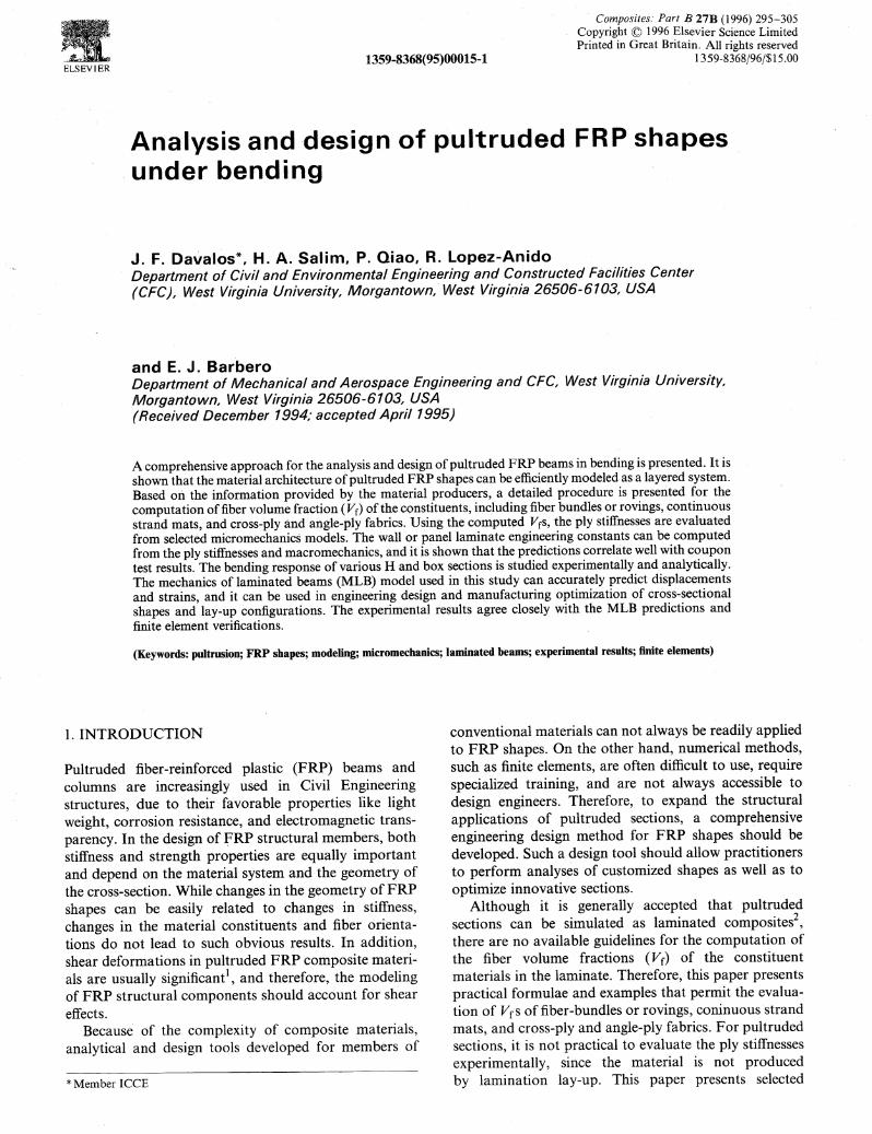
is significantly larger than the flexural component (lastterm ofD y in equation (11 )). The total bending stiffnessesin Table 7 are computed by equation (11), accounting forthe bending-extension effects (second term of Dy inequation (11)) in some of the sections which exhibitedminor lay-up asymmetries.
To verify the prediction accuracy with the FRPBEAMprogram, the test beams are also analyzed with thecommercial finite element program ANSYS 19 usingMindlin 8-node isoparametric layered shell elements(SHELL 99), which include shear deformation. Anaspect ratio of one (length-to-width) is used to definethe mesh for each member, and the input materialproperties used are taken from Table 5. The analyticaland experimental results are correlated next.
3.3. Comparison and discussion of results
As shown in Table 4, the panel or laminate stiffnessescomputed from the predicted laminae properties agreeclosely with experimental results obtained for the couponsamples of the 10 x 10 x 3/4" box section. These resultsprovide confidence in the computational procedure for
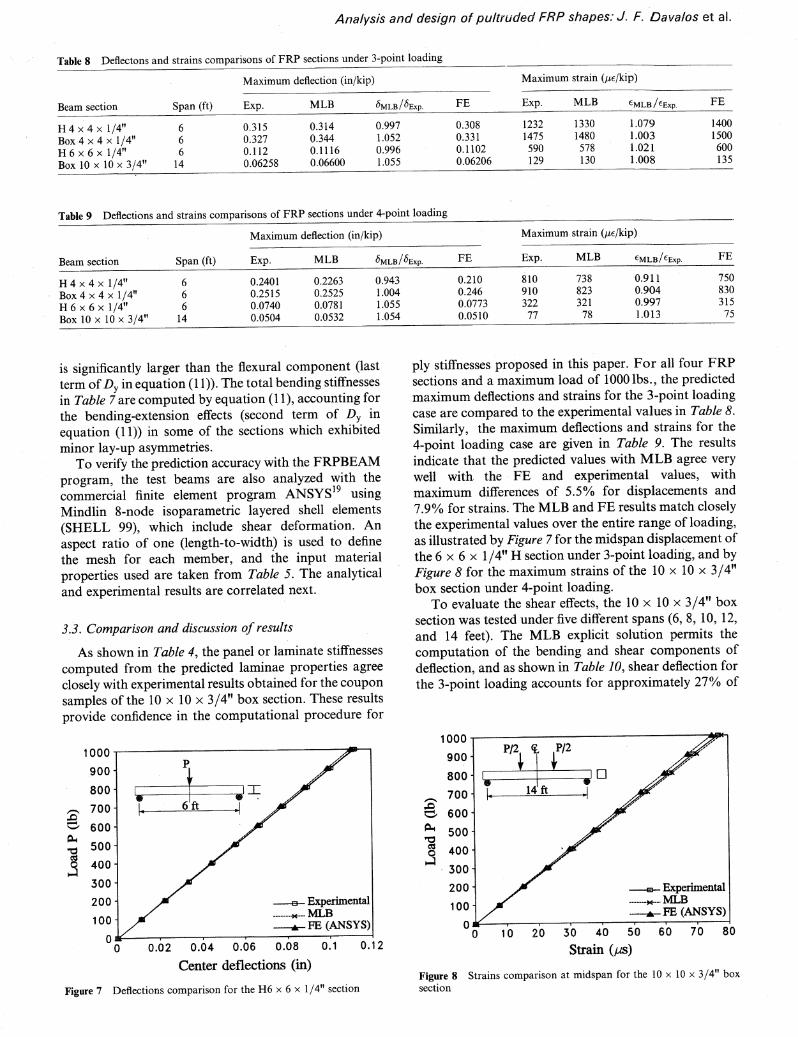
ply stiffnesses proposed in this paper. For all four FRPsections and a maximum load of 1000 lbs., the predictedmaximum deflections and strains for the 3-point loadingcase are compared to the experimental values in Table 8.Similarly, the maximum deflections and strains for the4-point loading case are given in Table 9. The resultsindicate that the predicted values with MLB agree verywell with. the· FE and experiinental v-alues, withmaximum differences of 5.5% for displacements and7.90/0 for strains. The MLB and FE results match closelythe experimental values over the entire range of loading,as illustrated by Figure 7 for the midspan displacement ofthe 6 x 6 x 1/4" H section under 3-point loading, and byFigure 8 for the maximum strains of the 10 x 10 x 3/4"box section under 4-point loading.
To evaluate the shear effects, the 10 x 10 x 3/4" boxsection was tested under five different spans (6, 8, 10, 12,and 14 feet). The MLB explicit solution permits thecomputation of the bending and shear components ofdeflection, and as shown in Table 10, shear deflection forthe 3-point loading accounts for approximately 27% of
Figure 7 Deflections comparison for the H6 x 6 x 1/4" section
P/2 ~ P/2
~o
--e- Experimental-------+e---. :MLB--.- FE (ANSYS)
Figure 10 Longitudinal strains for the 10 x 10 x 3/4" box section: (a)top and bottom flanges; (b) webs
(b)
8.00
2.00
:5 6.00.........",
'fJ~4.00
~
a .00 .......-r,.,..,.~r-1'"'1"T'T"T-M-rrr..,.,.,""I'-r'rrr~r-r-r-l~~r-r-r-r-4
-100.00 -50.00 0.00 50.00 100.00
Microstrains/load (tJSJkip)
Exp: c 6-ft + 10-ft * 14-ft MLB
10.00 -r---~~-~----..,...----, ----.
Span (ft)
Figure 9 Deflection comparisons for various spans of the lOx lOx3/4" box section
the total deflection for the 6-ft span, and it decreases toabout 60/0 for the 14-ft span. As with the other FRPsections, the ratio of experimental to MLB predictions isclose to 1.0. The deflection comparisons with FE andexperimental results are shown graphically in Figure 9.The longitudinal experimental and analytical strains forthree spans (6, 10, and 14ft) are compared in Figure 10,showing close agreement. Figure lOa shows the strainsacross the width of th.e top and bottom flanges, andFigure lOb shows the strains across the depth of the twoapposite webs. To study the Poisson's effects, transversestrains were also measured on top and bottom flanges,and the experimental results were within 100/0 of theMLB predictions.
4. CONCLUSIONS AND RECOMMENDATIONS
In this paper a comprehensive analytical and experi~
mental program for the anaJysis and design of pultrudedFRP. shapes under bending is described. The interactivecomputer program FRPBEAM is developed to carry outthe analysis of FRP beams, from the evaluation of plystiffnesses through micromechanics to the overallmember response through the mechanics of laminatedbeams (MLB) model. The proposed approach can beused as an efficient tool for engineering design by bothpracticing engineers and pultrusion manufacturers.
The results of this study indicate that selectedmicromechanics formulae can be used to accurately·predict the ply stiffnesses of the constituent materials ofthe laminate, including fiber-bundles or rovings, continuous strand mats, and cross- and angle-ply fabrics.These relatively simple formulae can provide accurateresults, provided that the constituent Vrs are correctlyestimated using the manufacturer's information and theformulae given in this paper.
The experimental study discussed in this paperincludes H and box FRP sections, and the MLB modelpredicts displacements and strains in excellent agreementwith the experimental results and finite element analyses
Analysis and design of pultruded FRP shapes: J. F. Davalos et ai.
with ANSYS19. The MLB model permits the computation ofshear and bending deflections separately, and hasthe ability to analyze any cross-sectional shape withsome minor restrictions. Therefore, MLB can be used toconduct parametric studies, and it can be extended tooptimization studies of existing and new shapes.
In this study, distortional effects, such as shear-lagand warping, which can be particularly significant forthin-walled sections, were not considered. Moreover, theanalysis is limited to linear-elastic response and doesnot include failure or buckling considerations. Theseadditional concerns need to be addressed in the design ofFRP beams, and the present formulation can be used asthe basis for further work in this area.
ACKNOWLEDGEMENT
The FRP sections tested in this study' were partiallycontributed by Creative Pultrusions, Inc. and MorrisonMolded Fiber Glass Company. The authors thankProfessor GangaRao and Mr Nagaraj for the use ofsome of the experimental results presented in this paper.
REFERENCES
Mosallam, A.S. and Bank, L.C. Short-term behavior of pultrtided fiber-reinforced plastic frame. J. of Struct. Engrg 1992,118(7), 1937
2 Barbero, E.J. Pultruded structural shapes: from the constituentsto the structural behavior. SAMPE J. 1991, 27(1), 25
3 Luciano, R. and Barbero, E.J. Formulae for the stiffness ofcomposites with periodic microstructure. Int. J. Solids Struct. 1994,31(21), 2933
4 Jones, R.M. 'Mechanics of composite materials', HemispherePublishing Corporation, New York, NY, 1975
5 Barbero, E.J., Lopez-Anido, R. and Davalos, J.F. On themechanics of thin-walled laminated composite beams. J. Compos. Mater. 1993, 27(8), 806-983
13 Makkapati, S. Compressive strength of pultruded structuralFRP shapes, Master Thesis, West Virginia University, 1994
14 Tomblin, J.S. Compressive strength models for pultruded glassfiber reinforced composites. Ph.D. Dissertation, Department ofMechanical and Aerospace Engineering, West Virginia University, Morgantown, WV 26506, USA, 1994
15 Lopez-Anido, R., Davalos, J.F. and Barbero E.J. Experimentalevaluation of stiffness of laminated composite beam elementsunder flexure. J. Reinforced Plastics and Composites 1995, (14),349
16 Whitney, J.M., Browning, C.E. and Mair, A. Analysis of theflexure test for laminated composite materials. In 'CompositeMaterials: Testing and Design (Third Conference)', ASTMSTP 546; American Society for Testing and Materials, 30, 1974
18 Lopez-Anido, R. Analysis and design of orthotropic platesstiffened by laminated beams for bridge superstructures. Ph.D.Dissertation, Department ofCivil and Environmental Engineering,West Virginia University, Morgantown, WV 26506, USA, 1994
19 'ANSYSUser;s Manual', Swanson Analysis System Inc., Houston, PA, 1992.
20 Davalos, J.F., Loferski, J.R., Holzer, S.M. and Yadama, V.Transverse isotropy modeling of 3-D glulam timber beams. J.Mater. In Civil Engrg 1991, ASCE, 3(2), 125
21 Nagaraj, V. and GangaRao, H.V.S. Static and fatigue responseof pultruded FRP beams without and with splice connections,CFC Report, 94-183, Constructed Facilities Center, West Virgi~
nia University, Morgantown, WV, 199422 Qiao, P., Davalos, J.F. and Barbero, E.J. FRPBEAM: A com
puter program for analysis and design of FRP beams, CFCReport, 94-191, Constructed Facilities Center, West VirginiaUniversity, Morgantown, WV, 1994