Page 1
ANALYSIS OF A CIRQJIAi' ARCH BY 'lllli 1(AYU:.1Gll·1UTZ MllTdOD ''
Tbeaie submitted to tbe Graduate Faculty of the
Virglnia Polytecbnlc Institute
in candidacy for the degree of
MASTER OP SCIENCE
iD
Civil EQgloeering
APPHOWD:
Dr. H. M.. Morris Dr. l>. l''rederick
Dr. u. M. Barker
May 1966
.Blacksburg. Virginia
Page 2
-2-
I. I..J.st of Figures and Tables ••••••••••••••••••••••••••• 4
II. Iotroductlon ••••••••••••••••••••••••••••••••••••••••• 5
Ill. List of Symbols •••••••••••••••••••••••••••••••••••••• 7
IV. Literature l~icw •••••••••••••••••••••••••••• • • • • • • • • 9
v. Hevieu of I~nergy Analysis •••••••••• •. • • •••• •. • • • • • •• • 11
A. Minimum Potential Energy and Castigliano's
First Theorem •••••••••••••••••••••••••••••••• 11
B. Solutions of Stable llqullibrlum Problems ••••• 14
VI. Choosing Deflection Functions •••••••••••••••••••••••• 17
VII. Beam Deflections by Rayleigb•Ritz Method ••••••••••••• 19
A. Simply Supported Beam ~ith Uniform load •••••• 20
n. Fixed ~nd Bemo witn Uniform load ••••• • •. • •... 22
c. Simply Supported Beam with Concentrated Load • 24
D. fixed ~nd Beam with Concentrated Load •••••••• 26
VIII. Tho R.ayleign•Ritz Method Applied to a Curved Beam • • • • 28
A. Derivation of Wiokler's Curved Beam Formula
for Strain ~norgy •••••••••••••••••••••••••••• 28
B. The Problem •••••••••••••••••••••••••••••••••• 35
c. Solution by a Conventional Method •••••••••••• J7
D.
&.
Solution by the Raylcigb·Ritz Method •••••••••
Comparison of Results and Conclusion ••••••••• 38
43
Page 3
IX.
x. xi.
XII.
!Iii Bibliography ••••••••••••••••••••••••••••••••••••••••••••• 51
Acknowledgements •••••••••••••••••••••••••••••••••••••••••
Vita •••••••••••••••••••••••••••••••••••••••••••••••••••••
••••••••••••••••••••••••••••••••••••••••••••••• Appendices
Appendix A • Fortran Programs •••••••••••••••••••••••• Appendix 8 • Def leetlon Functions ••••••••••••••••••••
53
54
55
55
64
Page 4
-4·
1. Liat of Piguros and Tables
Figure lia!
l. 5iwply Supported beam vith Unitorra Load ••••••••••••••••• 20
2. Fixed hnd Beam ~ith Uniform Load •••••••••••••••••••••••• 22
3. Simply Supported Beam or.11th Concentrated load •••••••••••• 24
4. f'txed End Beam v1tb Concentrated 1'>ad ••••••••••••••••••• 26
s. Arch Element 1D &lonaat1on •••••••••••••••••••••••••••••• 29
6. Arch Element 1D &lotatton •••••••••••••••••••••••••••••••• 29
7. Deformed Beam••••••••••••••••••••••••••••••••••••••••••• 30
8.
9.
Strain in aa Arch ElellMIDt ••••••••••••••••••••••••••••••• Axial Strain • •••••••••••••••••••••••••••••••••••••••••••
31
34
10. Ex-.le Arch (a) Data for Conventional Method ••••• •••. 36
(b) Data for Rayleigh-Ritz Metbod •••••••• 36
11. Horizontal Reactions Due to Unit 1oada •••••••••••••••••• 37
Tlble .flU 1. Comparison 0£ l>e£loction Compucatlone . ................. . 44
2. Comparlaon of Bead1Dg Homent Computations ••••••••••••••• 45
3. Conve1:gence o! the Series Solution •••••••••••••••••••••• 41
Page 5
-~-
II. Introduction
Tbe energy technique known as the Uayle13h•Ritz metbocl is
a very convenient cool tor Lhe analysis of def tectiona in etruc•
tures subjected to external forces.
Basically. the Uayleigh·Rltz method ia one in '-tllich a
position of stable equilibrium of a etructul'e ls obtained by
mtolmialag the potential energy of geometry and strain.
Speclfically 1 when a atructure ls acted upou by external forces
it vUl be deformed and the energy expended by the external
forces added to the energy of internal deformation vtl l be a
mlDlmum when that deformed structure baa reached equilibrium.
In application to atructurat problems. a deformation
function 18 first assumed, eitber as a trigonometric function
IDMtlns the requirements of a Fourier aeriea, or as a polynomial C>o
of the fol"ll 2_ a 0 xn (L->e). The function suiting the 'Y\.= I
boUDdary best la chosen, after wbicb the internal and external
eneru changes my be calculated, added up and mS.nimlzed by taking
the d•ri~ativea of tho aum with respect to the dieplacement
parameter• and setting tbaa equal to zero. The parameters c:aa
then be obtained for that equilibrium position.
In tbia tbeai• tbe Rayleigh-Ritz metbod i• used for the
aulyale of an arch where account la taken of the axial effecte
as well •• bending effecta. the method i• ft.rat illuatrated on
atraigbt beame vltb varloua loada and ~ ~unclltlona. It la then
Page 6
-&-
used to analyze a circular arcn with a uniform cross section and
hinged end condicions. Deflections and bending momenta due to a
uniformly distributed load are CO&DpUted at several points along
the arch. The deflect.ions and bending moments are aiso computed
by a conventional method uelng the dunay toad and virtual work
techniques. ·The results by tbe tw methods are found to have good
correlation when compared.
Page 7
-7-
111. List of Symbols
All a)'ml>ols are defined here except as otherwise noted.
a undeter.nined <!uefticients n
a radius of circular arc~
b L/2
b undetermined coefficient• m
E modulus of elasticity
f 1 detlectioD functions
1 moment of iuertia
k (x/L) proportional ratio
L length of span
M bending moment
n direction.a of external force1 1 n • l, 2, 3•••
N axial force along the beam
p intensity of distributed load
P COQcentrated load
P extunal forcf!a n
~ corresponding displacanente in the direction of forces P0
r (a+ r> • distance measured alons tho centroidal axis of a curved beam
S distance measured along an arc otber than the ccmtrotdal axis
t number of independent displacement parameters
u radial componeut of dieplaceamt of any particle, outward
18 poaitive. (u • u)
Page 8
-u
u•
u"
u v
0
v -v
·G·
radial component of displBcesaent of particles on the centroidal
firuc dcr!vac!vc of u uith rco1icct to e
second derivotivo o! u uith respect to s
internal strain Gnertr/
vohae
work done by external fo1·ces (potential energy)
circumferential component of diaplacement of a particle on the
centro1dal axis
v circumferential component of displacement of any particle
v • first derivative of v with respect to s
W total potential energy (W • U + V)
:1< distance measur(..-d alons a horizontal ::<•axis
X1Y rectangular coordinates
y distance measured along a vertical y-axis
y' first derivative of y with respect to ~
'!J distance measured radially from tho centroidal aKi& of •
curved beam
z Winkler's constant in the theory of curved beams (7. ~ 1/a2A)
radial angle measured from one end of an arch to ehe other end
longitudinal strain
radial angle measured from the center line of an arch
9 rodi&l on9l r.Muuiut·-1 fr0Cl1 one end 01' an arcb
Page 9
·9-
IV. Literatura R~"View
lt wae Lord nayletgh who first developed the Rayleigh energy
principle for solving problietn9 ~~nc9rnin,g elasti~ d~flecttons,
stabi lit)' and the .frequ-!l.t;M:Y of vibration. In 1877, 1n his famous l text "Tne 'Ihoo:t"y of Sou.'ld," mall)' pI"actieal ~las u111re shovn
for the uso of the Ger&)' principle, but uer12 all limited to one
term instead of a series. Years tater, in 1908 a Swiss scientist
by tbe name Walter Kitz developed tbe same principle indepewlently
aod excended it with tbe uae of an infinite series to deal "11th the 2 3 problems. Tvo papers of bia • have been publlabed which give the
matbematical proof of the convergence of the series and also the
application to many intereatlng problems.
In 1873, Alberto Caatigli.ano published the theor8Cl28 that bear
bis name as a tbesla for the Diploma of Engineer at the Polytechnic
Institute of Torino, Italy. In 1879 CaetigU.ano's first theora; \i&S
pub 11abed in book form. lt says that for an elastic body which
obeys Hooke's la1il and the principle of superposition, if the body
~ere acted upo11 by concentrated forces and U the strain energy is
expreaaed as a funct1on of the applied forces, the partial derivative
of the elastic energy with respect to one force is equal to the dis•
placement of the point of appU.cation of chat force in tbe direction
of that force; .<..~ d lJ ==-L ) of=;\ -n Caatlglt.ano'a second theorem shows that for an indeterminate
structure, the values of the redundants must be such as to make the
total internal strain energy a IDinimum, vhere the energy is produced
Page 10
-LO-
by the application of a given system of loads.
Soon after 1900 Stephen Timosbenko made many contributions
S.n applying the na)lle:i.gh•Ritz method to ensiooeriog problems,
especially :lD solving stability p1·oblems. llis t."'10 earliest Russian
papers were dated 1907 and 1908 1 and later on, he published several 4 c papers in western ~uropean languages. , ...
In l91S, another 1{.usaian mathematielan, B. G. Galerktn, released
an article "Series Solutions of some Problems of Elastic }iquUibrium
of Roda and Plates.06 Tbe method of Galerkin is of much wider scope
than that of Ritz. When applied to variational problems w:ltb
quadratic functiona, it reduces to tbe Mt: method. An application
of Galerkin'a method in a non-linear problem can be found in an
article by D. U. Panov. 7 S:lnce the presentation of Galerldn's
method, a DUD>er of l<usslan scientists includins Leibenzon, Panov,
Papko, Protusavicb, Stepaniants and Sokolov have worked out &nan)'
valuable appU.cationa in different aspects. 0 Tbe Theory of Elasticity"
by P. F. Papko8 ls very rich io material.
lD applytag the Rayleigh-Rita fDGtbocl to arch analysis, Winkler'•
tbeory9 of curved beams is uaed in deriving strain enerS)'.
Page 11
v. Keview of Energy Analysis
A. Kiniswm Potential energy and Caatigliano's First tbeoreai
When a structure is loaded, the lo4ds cause internal stra1.n
and the work done by the loads \.Jill be numerically equal to the
internal encrw of defonnation. provided there are no thermal or
other loHes. Stated algebraically, tbe loss of potential onergy
of tbe leads (negative work, V) added to the potential energy of
internal strain (U) wst equal zero.
Any technique for the evaluation of work and strain ea.argy
in structures subjected to loading that does not provide for an
exact evaluation of either work or strain energy nor take account
of losses vill result in a sum of potential energy (W • U + V)
uhich inay not be eqwil to zero.
In order to obtain a solution then, the value of W may be
calculated and minimized. '1be minimum value wl 11 provide the beat
solution; a zero value \fOuld provide an exact solution. lo the
evaluation of the effecte of loads oo structures where fd.ction and
thermo t losses as wel 1 as some forms of strain eneri;c· (such as shear
strain euet:gy) are neglected or a deflected shape is assumed, an
exact solution my not bo possible, so the best solution 1• that one
vhere the total computed potential energy is a minimum. Where tbe
Rayleigh•Ritv. method is uaed and the total potential energy is
exprosaed is expressed as a series, when oore terms of the serieti
are evaluated, the anawor tends to be l'llOre exact.
Page 12
-12-
The Rayleigh-Ritz raethod applied in structural analysts is
based on the theorem of mininlm potential energy. It can either
be a funcci.on of one parameter or more than one parametaT. By
taking the derivattves with respect to the parameters and setting
them equal to zero, these parametara can be determined and become
the coefU.cients of the deflection !unction. l"he total potential
energy consists of bJO parts: (a) tba etrain energy of the deformed
body. and (b) the potential energy of forces .Ctf.n8 on the body to
cause that deformation.
The "Principle of Virtual Displacementsu eatabl1ahee that the
necessary and auff icient condition of oquiU.brita of a structure is
that the sum of the external encl internal work vaniahesJ or for
every virtual displacement, the loss in potential energy of the
external loads acting on the structure added to the increase in the
strain energy equals ~ro.
Z.'rom the theoraa of vb·tual displacements 10 -t..
dU • ~ Pn~ (1) '>'I.= I
where U • internal strain energy of all forces
P • external forces n
'In • dloptacemente of cbe forces
t • total ms:iber of f orcea
For any force
dV •-P do n D 'U
where V n • potential energy of a force
(2)
Page 13
from ~quations (1) and (2) -f..
dU • ~ • dV n • •dV h.::. /
so t.:.nat d (U + V) • 0
where V •potential energy of oil forces
(3)
The total pot.entia1 energy oi the structure has o stationary
'1alue which does not change bec:ause of infinitesimal displacements
if tbe structure remains in equilibrium. ln other words U + V is
e minimum ./:
while v • ~ vn n.::. I
(4)
From this representation, it can be seen that the theorem
ot virtual displacements and the theorem of minimum total potential
energy are essentially tlle same.
In a structure, the ~-ork done during an imaginary displacement
variation f> q on the state of strain by the internal stresaea is
equal to the negative of che product of ~ q aud the first derivative
of the strain energy with respect to q. io,
From equat:l.oDS (2) and (5),
and
-p, $~ +au si ==-o l'l h o f n Jt
p =- C;U h. d tn.
(5)
(6)
(7)
Thia is tlle expreaaion of Castf.gliano•s first theorem wnicb
Page 14
-14-
actually may be considered as a special case derived from the
tbeorem of mintmw:i poteutial energy in "Which a set of equations of
equilibrium .are obtained. According to Castigliano'a first theorem,
one equation of equilibrium ia obtained at a time from the partial
derivative of the strain energ,y corresponding to a particular dis•
placement. The latter approach differs from the former only in form
and they are intercbangeable.
If the internal energy of a framed. structure is expressed as
a function of the relative displacements of tbe external forces,
the resulting expression is auch tbat its differential coefficients
with regard to those displacemeata give the values of the correspcmdiog
forces. ie,
p • D
au -0 <In On the contrar)'• U the interoal energy of a framed structure
is expressed aa a function of the external forces, tbe resulting
expreasion is aach that its differential coefficients give the
relative displacements at their points of application. ou
and <lo • ~ (8) n
Thls theorem ls very important in strucwral analysts,
especially in dealing vith statically indeterminate problGmS and
tbe analysis of fixed end arches.
B. Solutions of Stable Equilibrium Problems
The equilibrium condition of a structure can be expreased by
Page 15
-I~-
the differeut1al equation which is an expression of Newton's third
law which states tbat the action and reaction must bo equal and
opposite.
From theories of strength of materials we get the relation
between tbe load and tbe correspondf.118 deformation caused by the
load lo iodividual beam elements of tne structure. The differential
equation is;
d4~ - -fJ d-:(4- E-1
where y • transverse deflection.
x • distance in the longitudinal direction.
(9)
p • transverse load vhich can be expreased as a function ot x.
~I • flexural rigidity of ~ne bea~ clement.
Thia dUferont:t.al equation can be applied to each individual
member of the structure. A solution is obtained by combining the
individual solutions in a manner tbat satisfies force and displacement
campatibility at the boundaries of those membere. This combination
involves tbe solution of algebraic problems which may bo chosen in
tet'IDS of displacements or forces.
Using a different approach the equilibrium problem of a
structural system can be expressed by the minimum po~ential energy
theorem. Tbe equilibrium position ol.: a structure is that position
of minlmura total potential energy. The work of the forces can be re-
placed by a ~ork function, so instead of solving the tedious boundary
Page 16
value probiem uith a differential equation, a function can be found
to give a mininum of the integral in wbich the potential energy of
the etructure is expressed.
The mat:bematical problem of determining the minimum of an
integral 11 dealt uithin a special branch of the calculus called
"calculus of variationa,11 and this is incorporated in the method used
for the solution of the problem in Section VIII.
Page 17
-:7-
VI. Choosing Deflection FunctloDS
Whether tb6l Rayleigh-Ritz method can be a auccess depends
011 whether one can choooe suitable functions. lf .function~ are
selected without due regard to the individuality of the problem,
the analysis may become unnecesaar11)' lengthy and laborious.
'Ihere ie no general rule to follow. Intuition and experieaco may
play a great ..,.rt in it. To know and compare problems of similar
patteroa can be a great help. If a large number of terma are
wrked out, one can possibly get good results and, in most of the
cases, even an exact solution. But for engineering use, while
taking tbe leaat effort to get a solution, one has to follow these
gcoeral rules:
(1) It ls helpful to ~ the approximate deflection features
of the structure so the most likely dof lection functions can be
selected accordingly.
(2) Tllere are oo theoretical restrictions as to the form of
the deflection functioD&. functions of the polynoroinal form, oc:> 2 •nxn (L-x) ( J.O)
Y\=-1
and the trlgouocnetric form Cc> 2_ •n sin (n~x ) (11)
are generally used. 'l-1::.\
(3) Tbo major requirement that bas to be met is to select
functions which converge rapidly aad can satisfy the boundary
conditions of the given structure. lf thia can not be done, it is 11 necessary to the use the method of Lagranse mulcipliera.
Page 18
(4) It muot be eaphastaed that in tho majority of cases,
satisfactory results can be obtained onJ.y when the functions t 1
form a syat• of orthogonal functions from wbich a aet of
consecutive functions cay be cuosen fo1· the fo1-mtion oi the
expreosion. The ortnogona 11ty relations w!1ich exist between tho
termo of such a sequcnco will considerably simplify the energy
expression (W • U + V) and tbe rest of the analysis. 'lbis is the
reason uhy the t•ourier series plays such an important role ln t.be
Rayleigh-Ritz method.
Page 19
-19-
VII. Boot! lleflectiono by the iU1~;1cigh-lt1t7. Method
1n the fol 'Wing illustrations, the structures are shown
vith varyins cond1tiona of loado and supports. In •ch C11se,
an equation for the deflection y is assumed in the foaa of a
trigouomatric series or a polynom:oal. function. lbo internal
strain energy U ia calculated from tne relation
a • !!f t (y")2 c1x 02>
The loaa of external iJ)Otential energy of the loads due to
loading is calculated from the relation
V • • lL p y dx (13) 0
These quantities are added, differentiated with respect to
the 1Ddetel1Di.Date displacement coefficients, and aet equal to
zero. The values of the c11eplacement coefficients and the total
diaplacement is then determined.
Page 20
A. IS..,17 Supported 1 ... with \haifora Loa41
y
r L
Pigur• l
00 rnr.x. Assume~= La,,. Sin. ( L )
n.::1 00
Now u = Jtt? :t )2 dx. =ct X-tk) ~:z. !.,-n +_a.! PoteDtlal Kaeray V of the applied load ii
V=-( hd~ -J> i 1 a.,. Si" tnix~dx
= ~ !b[a"( CO.$ nrr- I )l n=1 nlT ~
Z~L 00 -L There+oRe - v = 1T I n Qr\ n=v~,···
Total potntlal aer17 • U + V
Page 21
c(U +V) =( ir+) E:I ( n4)( 20. )- ~f. p L)=o ~a." T L:1 " n r ir a = 4 (J_)S ( ~ L 4 '
" n. lis.E-1 J n = 1, ~, s, ···
IW»atitut• a into y D
Le+- x=L/~
~ (a.pprox.)=O. o 1~07119 { H*)5 + (:~)r;.-('t ); + · ·) t~4 =C ( t~4)
~(e.m+)=~ ( n4l
y c
1 tera 0.0130712 2 terma 0.0130174 3 teraa 0.0130216 4 term 0.0130208 a.act 0.0130283
Page 22
-22-
I. 11.zed EDd ·-witb U.ifora Load y
Jl
p f 7 ___ __,_ x J 4 ' ' ' ' ' ' ' ' ' ' ' ' ' ' 'r4 ' ' ' ' ' I'
0 ·L/2
Plgur• 2
pclx
L/2 "
Thi• probl- caa be aolved by aHuaiq a polyaoainal
fwactioa that will 1uit the apeclal boundary coDditiou for a
f ized mad b-. A cletaUed explanatioa oa the choice of
fuactioa i• &iY91l ia Sectioa VI.
Lt+- * = a. ( 1 - ( ~ ) 2 ) 1-
=a [1-2(~}2+f;t)
~·=a. (-4(~)+4 ~: J ~''=a L _±_ + 12 :x:. 2 ]
[ b2 b+
Check for bouadary conditiou
~ = o ~"':: o w'1en X = i. b
~ = ~ ~ / = o wht.ra x = O
,.,
Page 23
•Zl•
'?be total poteatlal ..ut be a ldU.U., ao tbe derivatlye vitb
reapect to a muat be aero. ie,
Subatitute tbe yalue of a iato 7
F-o r x = () 'i - p L4 0 i - ~84- E:-1
'Iba •- •• obtaiaed t.7 •• aact •tbod
Page 24
-24-
c. lillplJ Support .. •- wltb Collceatrat .. Loa•
y
kL
•
L
Figure 3
lub•tltute tbe ••l•• • lato 1, therefore •
Page 25
For def lectioa at the center vban P 1• at the canter
ZPL;, J l ) ~ (o.pprox.) = Tf4 E:-1 ( '-+ 34 ... ~ -+ .•.
= \ ( \+l .,.._!_ -t··)PL~ 48.7t14f ~ '=11 E: I
= c(~~~)
~ (ex<1ct) = ~ ~ ~~~)
., c
1 t•ra 0.0205320 2 tel'IU 0.0207855 3 term 0.0208140 exact 0.0208333
Page 26
-26-
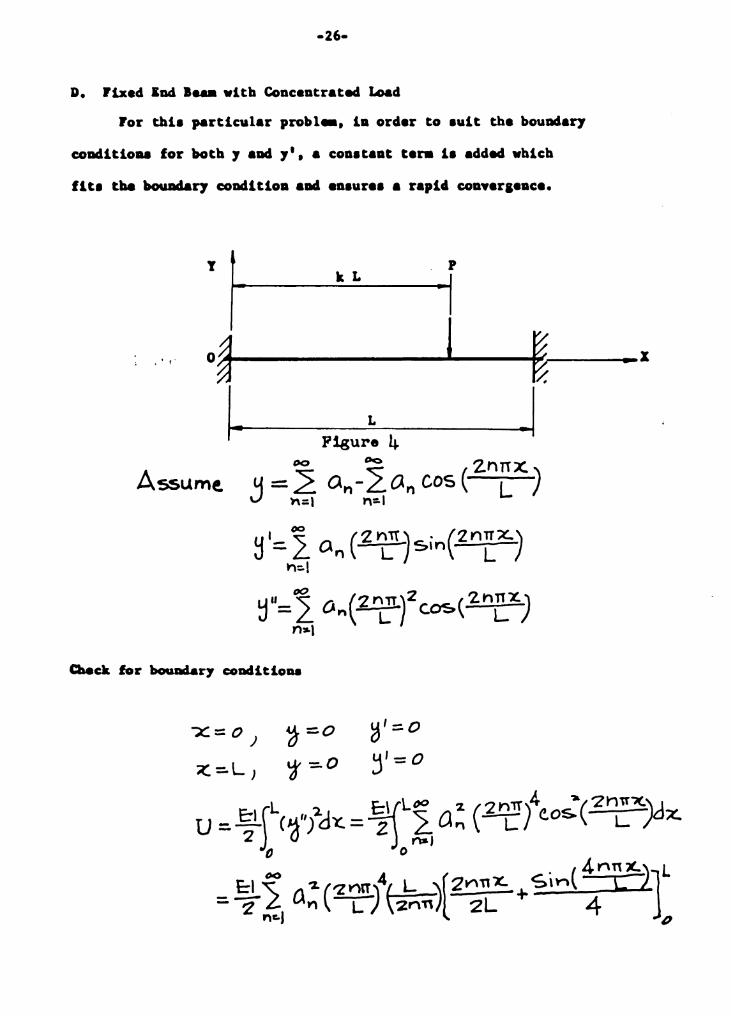
D. Fixed ED.cl 1 ... with Concentrated Load
ror thi• particular probl .. , ia order to auit the bound•l'J
coDditiou for l»otb '1 aDd 7'• a conataat tera b added which
flt• tbe bouDdal'J coDdltloa and enaur•• a rapid cou.era•ace.
y L k L p r -1 .. o~~-_...__I --ftij~
1. L -1 Assume.
~ '= 1 a" ( 2 ~lt ~ sin(Z n~x.l ti::. I
~"=1 o"(2nL1!.)2c:0$(2n~~) n:a.1
Page 27
"d(LJ+v) :::.o dClN
-21-
~ L.za .. (21I_N)4- P[ J-c:~ (2N11~)] =o
LQ.+- ~= Y-z I Q2 = Ct.it : Col (I= - .. = 0 :. N:. I,~. s:,, ...
=- 2P( J-CO&( 2Nirk.)] ( L ~+ ON ~IL 2N~)
lubetitute .. iato equation to find 7
Deflecticna at ceater when P at center, let z • f'; k • 1/2
400 4 BP 3o y ::. 4- p f_b__~ L LL) ( l + I ) =- L ( 1 -+ l-,,. + ~ .. -+. -) o f=I L \ 'Z.n} >i=-I ~ n E:-1 ('211)4 ~ ~
u = PL.3. ( ·, +1-4 +1-4-+· .. ) = c ( PL~j v I ~c;, f:: I ~ 8 E: I 7
~ ( c-xaCJt) = PL!> I~~ £:-1 1
l tera 2 t•ra1 3 tera1 aact
c
0.0051020408 0.0051650289 0.0051721151 0.0052083333
\ i
Page 28
-28-
VIII. 'Ille 1'ayleigh•k1tz Metiwcl Applied to a Curved Beam
A. l>erivatlon of Winkler'• Curved Beam Fonula for Strain l!:nergy
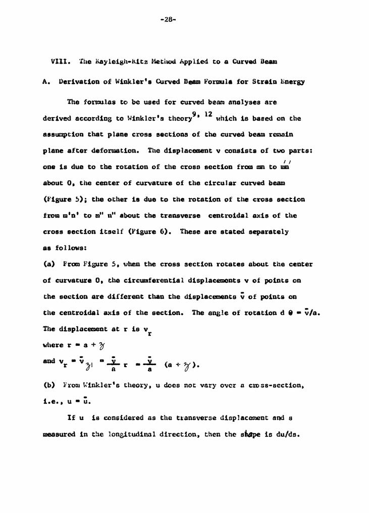
The fonnulas to be used for curved b2M analyses are 9 12 derived according to Winklar's theory • uhich is based on the
assumption that plane crose sections of the curved beam remain
plane after deformation. The displacement v consists of two parts: I I
one is due to the rotation of the croso section f rcm mn to mn
about 0 1 the center of curvature of tbe circular curved beam
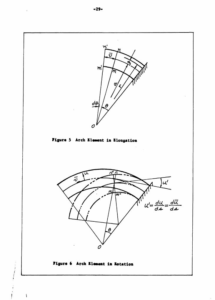
(Figure ~); tbe other is due to the rotation of the crosa section
from m'n' to rn" nu about the transverse centroidal axis of the
cross section itself (Figure 6). These are stated separately
aa follows:
(a) From Fi!,'Ure 5 • when the cross section rotates about the center
of curvature o. the circumferential displacements v of points on
the section are different than the displacements v of points on
the centroidal axis of the section. The angle of rotation d e - v/a. The displacement at r ie v r where r • a + ?f
- -aud v • v '1>-I • ....!... r r o a •
.-L a (a + ~ ).
(b) lr'rom Winkler' s theory, u doca not vary O\rcr a cro ss-scction,
i.e., u • u. If u is considered as tho t~ansverse dinplaccment and s
measured in the lonsitudinal direction, then the sfiape io du/ds.
Page 29
i i I
llpre 5 Arch 11 ... at la lloaaatloa
0
flpre 6 Arda 11--t la lotatloa
u.'= du. = da. dA- dA-
Page 30
-30-
aK • .s!!l • u. (14) ds da
While u' ls the angular displace:aent. This can be illustrated
very wel 1 by a straight beam. 'Ihe tangent o ! a deformed curve
f.s as obcwn in 1•1g. 7. If u id taken as tne y in the straight
beam aod ds as dx, then du/da and dy/d~,. have close similarity.
(LS)
Figure 7 Deformed Beam
From tile small shaded triangle in !1i&ure 6. 'IC can see that
the displacement v caused by u' <~ du/ds) along each point is
dlffercnc and to in proportion to ;r , and v ~2 • • ~ u • • from
Fig. 6. when J is pooitive, v is positive_ \Jhen 'jf is negativo, v
negative. By superposition, u • u 1f -v • - J (u.) ·r ( l + a ) v (lb)
'l'he strain of a fiber at distance J from the controidal a;tis b
e, in 1''1g. 8
dS • ( l + r. ) ds a (17)
Page 31
\. ~\
before detonnation
--31--
P1gure 8 Strain in An Arch Element
Page 32
•32-
Tberefore dv dv dS = ~) (I +a:-JdA.
- ~~ d-v - r_ a _) -v' -\a+J-)dAL -ra-'~l
(18)
•• l• tbe darl••ti .. of • witb reepect to tba cantroidal dieplac....at ••
Pl'Oll &ca• 16, (} = - j-U.' + (I-+ f )-V-
Tberefor• Ef2_= -~(dzu_) a.+r(d.-O)=v' d ,L () d A.! -t- a. cl A.. (19)
... d.u a [ (c/ 1u...) a-+r(d.J)} t_"- rl.<:!. = a+J- -} dA-2 + a c/A- uo>
= -(Qt'°)( d 2'll...~ + d::Y_ :=. -( Q J-') u_''-t 1J I a-1j dA!) dA- a-1ti
Before deformation, the fi~r lenath dS at ~ dietance froa tbe
catroid 1•
dS=(a+~)dB
After defol'llatioa it ia
dS+LldS = (a+g +u.) de
... AdS U -t" = ds- ==- a:,.r
1.-taa,
(21)
Page 33
rraa Hookea Law
lataaratiaa o.er th• whole croaa aactioa
. N=f[<rdA =jf E-(-V'-t ll~::Ll.')dA
=ff E-V 1dA +jf(J:iJ.~dA-fft ~a~lL')dA rraa Wiaklar•a 12 theory
aDd
J'IcJA =-A(i-+-Z) Ja-f g a
JJ J2dA =lAa. ~-It
(( jdA =--ZA JJ'a-tcr
N = C: {< u-+ a-v}-t z( u. -t a-zu..") J Tba ltaDdiq .,..at M caa thea be found
M ~ff CTJdA =f[E;tJdA = &/JJ-(-0'+ u.~::u.)dA
(22)
(23)
(24)
(2.5)
Page 34
= o -r (- l A ) &u. - a E-U.:' (a z A )
= - E:-A 'Z ( u_ + a 2u")
Tbe total atrala ener11 can tben be calcvlated.
Piaur• 9 Axial Strain
rrom Jipar• '• (T =f='t \T dA = r:r d J df = E::--t. dJ d (f
d U it'< .trdA)d (-tdx.)
t'<ctdJdtf )dt dx d
=(~)t12 dJ d'Jd-x_
and U ::.JJ[<i-J-E,2 dVa
Since dVa = dS dA =(a+J)dBdA
(26)
(27)
(28)
(29)
Page 35
U bewmes
U=tr:-jdoff (o-1JJ°'" t dA
=f j adoj[ a;J'{ u~=tu"-+ v'/dA
= f ~:. f u-1- a V') 2 -+ ( l.l-+ a 2u.."f z} dA.. <30>
which 1• the 1traia aaer11 formula to ~ uaed ia eo11putiD.1 ~otal
potential energy.
B. The Probl•
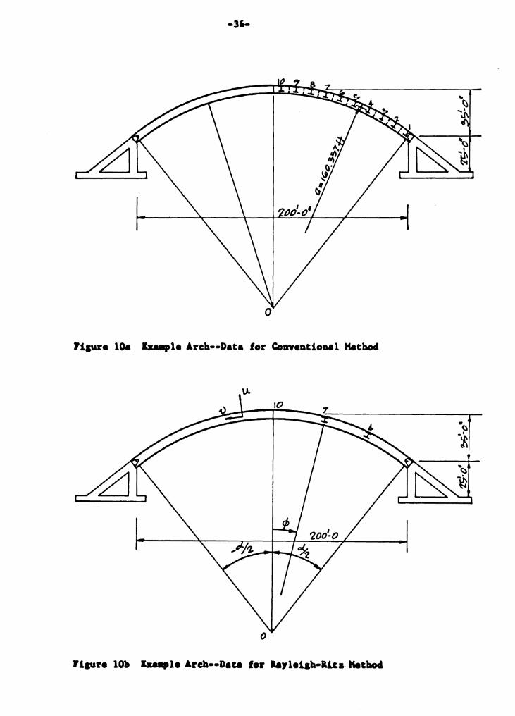
To illuatrate the laylaigb-Rit& .. thod for aolv1Dg arch
deflectioaa, a typical arch problaa 1• cho1en. The arch 11 11.mply
aupportad; the unifora cro11 aection rib i1 a 24WP130 1teal curved
beam with a total area of 38.21 1quare inch••· The moment of inertia 4 i1 equal to 4000 in i modulua of ala1ticit7 11 30,000,000 p1i. The
load i1 a1auaed uniforaly diatributad along the arch at 189.6 powad1
per inch. When computing deflectiona b7 conentional .. tbod, the
unifora load ii treated aa coDceDtrated load1 of 24.565 kip• each
actina at the center of ••a-ant• each 10.798 feet alona alona the
arch. (Sae lipar• lOa)
Page 36
0
Ji.aura lOa lxallpla Arcb••Data for Conantioaal Method
0
Page 37
-37-
C. Solution by a Conventional Method
The redundent horizontal force (H) of the atructure when
acted upon by the equi.,alent unUora load vaa evaluated bJdthe dmmy
load .. thod uain& the .,irtual work technique and found to be 333.9
kipa. (See lleferesace 14, paa•• 546 to 551). In order to find de•
flectiona at point• 4, 7 and 10, a unit load vaa placed at point•
4, 7 and 10 reapectivel7. The horisontal redundent ructiou clue
to thue unit loada were computed aa 0.54, 0.95 and 1.08, reapectivel7.
<••• 1igur• 11)
1.0
--0.54 0.54
1.0
/
1.08 \
\
\
Figure 11 Horizontal B.eactiona Due to Unit. Load•
1.0
After tbe redundeot• are obtained, the atructure can be treate4
aa atatically deterai&aate. Then th• bendiq .,..nt can be computed
at uch aegaent.. Let Ki be the bendina llOlleDt for each aepent i due
to Ullit load• at 4 9 7 aad 10 reapectivel7. To eo11pute the unUora
load deflection at point 4, for example, the followiDa for11Ula i• uaedz
(31)
Page 38
·38·
Wbore ,6 4 is the deflection at point 4. n is the number of
segments in the arch and S is the length of eacb segment. Like-
"1ise, 1J. 7 and ~ 10 can be calculated.
The deflections b 4 , ~ 7 , and 6 10 were computed to be
•0.74, 0.25 and 1.42 inches respectively, with positive oigns for
vertical dO\cltN8rd and ne~tive signs for vertical upward deflections.
o. Solution by the Rayleish·Rf.tz Method
To compute the strain energy of the deformed arch using the
Rayleigb•ltitz method, the form.ala for curved beams by Winkler12 ia
adopted. From the geometrical relation, the potential energy V can
be obtained. Adding this to the strain energy U gives the total
potential energy. The u and v displacements are assumed by using
cosine and sine functions. The geometrical features can all be
satisfied if the odd tel:IDS and even terms are used for the cosine
and sine functions, respectively. (See t.quation 32 and Fl!Jire lOb).
By taking tb.e partial derivatives witb respect to the undetermined
coefficients and setting them equal to zero, the coefficients a0 and
bm can be obtained. The coq>utation 0£ a and b t.1as done by solvina n m simultaneous equations using the digital computer. 'lbe equations
are developed in this section and the Fortran program for the solution
of the problem iu shcMi in Appendix A. '£be complete mathematical
development follows.
Page 39
·39·
(32)
.{) = ~ b,., Sit) (m.:?") !'>P?,4,~
when cp = 0 I U,_ ~ Q I -(} ::: 0
n,:: ± ~ u..= o 1J.::o u_ ''=o T z I I I
U. +a2 U.'' = ~ (I- n 2~J a,, CtJs(n~</J) n:: /, 3,S °"
Subatitute iato Equation (30).
, J[ <. cn-m)7[ -<. (1'1+1?1)") Let- ~ ::. !!::.. .vin 2 + ..J/n z
nm Ti ( n-,.,.,) TT ( n + h->) 77
Page 40
-40-
or
ror th• potaatial aaer11
T - cl. { :< n } m+n.-1 nm - rr n~-l'n'Z. (-1)
Y =-J:-ti>~~d~ =-~4~ (-u. c.os<j> + V &in<j>) dcji -;z -~
::: ~0~~2 (~ a,,c0$ n;_i)cos<j> d<j> --~ n:I
~ o.f (I a., si.., "'<;,1 )s;.., cj> dcji -% ~~
Qy- v = r"'~o( L. Sin '2 -t '$\n z a,., + .p_ ~( • (nTT+ol.) . (nTT-al)J h:.J nTT+~ nlT-o{
oo ( , I t'Y\TI~) MTl-ol)} iao(.,2. :Sin\ z - S\n( z b I'\"\-: ;2 M "Tl -t-o{ m "Tl -oil ""
L I 00 [. ( nrr+ca..: nn-ol) Q.+- I = L Si to'\ -z ) + ::>in ( 2 J
r')::.I hTT+-'. Y1TT-o(.
Vkic~ .. , be mcpraaaecl ••
00 !l::l J = 2:_ ( - I ) 2 2 l'ITT c.o$ ~ t'12.1T2-~'2. n::. J
A I "'° ( w.TT+ol) ( mn -ol...~ j SO JI= 2 ($in 2 / _ Sil'") z )
t°)I:.~ mn+o{ mn -oi..
o.-""° J!l . o( .[ =- 2, C-\) 2 2rnTT $,n ~
""~'- M'21T2 -o<'2.
(J4)
(35)
(36)
(37)
Page 41
~h
The total potential ner11
V•U+V
rr- 14lutiou 33 throuall 38,
4a. "° r"'\ in '2. 2 rn TT ' ;L W "° :L. ... }
:o( f ~/I + 1 (I - .,{,. )) 0. n 1 :z ( ol. z. ) b.., T
r'Y'•l"1-I
~ ~ a b (!!nl'~( 8 n Jc-1) '2. L L .., W\ o{ I TT n '1. _ "'12:j n:.I m="l
B -Pa~o1. ~±:.a ""'~ b ] E:-A 1 2 t'\ 2 m
Taklna derl'Yati••• vitll r••pect to •w viler• M • l, 3, 5, ••••
-t
(38)
(39)
4o. "dW N2.111. 2. 60 1'9'\+W-l
E:A aa = 2~(' + z('- o(;L ) JaN + 2. (-l) 2 b"" 8 ,.,...N -N ~2
t 8 f>o.:a.'TTol (-1fiN CP5~2 =. O ~A N 2 TT 1 - o( 1
(39)
Takiaa derivative with r••p•ct to~ where K • 2, 4, 6, ••••
4a -aw (M1T z ~ t.A+n-' 8 \. .. i=-A ab .• = z.£ 7) ~-+ L H) 2 a., -~·~,,_
,,,, n:. I
+ 8 tal. TTol. (-1)~ M $\ narz.. - -o E:A M 2 n'J.-o('- -(40)
l--.1, n,. 1 ) Lt.+ X ~::. 2o( ( 1 + Z ( \- 0 J.2· J
Page 42
14lut1ou (39) •• (40) caa be vritt•D ••
00
Xt-.1<'.'.Aw-tL YNmbrY\-t-IN =-o rn~2/f,(o
• - l, 3, s • .....
K • 2, 4• 6, ••••
By aolvia& th••• •~l&aneoua equatioaa, all the coefficieata 8H aDd ~ caa be obtaiaed. Subatitute the 'Y&luea of .. aDd ~ iato lquatioD
(32), tbe 'Y&lue• of u aDd y caa be obtaia..S.
(41)
(42)
Page 43
E. Comparison of Rcsu 1 :·s nnct C.onc !ui.'lie>n
the deflection funct:ions assumed to be
U a ~ a n:.J,?.,S n
cos
and v c:: ! hm Hin ~:::2,4,(p
as in £quotion .32. boundary cond1Lions for the pirmed-und arch were
satisfied and the P..ayleigh•Ritz method was used to detet-mine deflections
for t11e loaded arch presented in sections VIII • n and D. '.fhe rcsul ts
are given in Table l for points along the arch approximately 1./6 apart.
'rbe bending moment
M a • I.AZ (u + a2 u")
was ~prC$Sed as n function of u and values were deLermined at
corresponding points. These are given in Table 2.
In the development of the deflection equation, particular
difficulty was encountered in dealing ~tth that part of the relation
introduced by the tenn (u + av' )2 from Equation JO. nle auaaatloo of
cross product terms resulted in a series of simultaneous complex
equations t:o be solved. Initially lt was atte111pted to use a siq>liU.ed
form with pairs of simultaneous equations. but there was evident dla-
agreemcwt with the results obtained by the conventional mothod.
Therefore the calculations were revised to work with groups of sixteen
simultaneous equations to solve ~eta of eipt a terms and eight b D m
terms properly related in each equation. Both sets of results arc
ahawn in Tableo l and 2.
Page 44
Tabl• l
Comparison of Deflection Computation•
Location 10 (') 7 4
' o.o• 13.o• 2s.1 •
Deflection Computation• \I v \I .. u v
Method in in in in in in
Rayleigh-Rita -2.57 0 -1.26 0.35 +-0.55 0.28
Conventional (rib 1horteniq -1.42 0 -0.25 0.06 +-0.67 0.31 neglected)
Conventional (rib aborteniq •2.46 0 -1.20 0.40 +-0.60 0.32 included)
0
Page 45
... ,_
Table 2
Compariaou of Bendisaa Holleut Collputationa
LocatioD 10 (£) 1 4
' o.o• 13,0• 2s.1 •
Method f t•kip• f t•kip• ft-kip•
llayleiab·Rita 153.1 33.7 -154. 7
Conventional (rib 1hortenisaa 132.2 12.4 -153.8 neglected)
Couventional (rib 1borteuiq 148.0 26.2 •145.0 iacludecl)
10
0
Page 46
In the Rayleigh-Ritz solution where sets of sixteen related
coefficients were determined using sixteen simultaneous equationa.
it was interesting to note that the resulting series expreselona
for def 1ect1ons converged very rapidly. The pattern of convergence
is shown by the tabulation in Table 3.
Following the conventional dumray•load method utilizing the
virtual•work technique was presented in keference 14 1 the solution
for the illustrated problm of Section Vlll•C was developed and
programmed for the camputer (see Appendix A) to determine bending
momenta aod def lecticma. These results are also presented in Tables
1 and 2.
It should be noted that the Rayleigh-Ritz method developed
and preeentod lo tbis thes:la takes account of axial as we 11 as
bendina strain energy and so includes the effect that la referred to
as rf.b shortening in arch analysis. When properly applied, therefore,
the P.aylelgb•Ritz method provides a more accurate solution for
deflections. On the other hand, the equations £or bendins moments
must be developed from the equationa tor deflections, which require&
addition work and may not, in general, result in tho ISIOSt accurate
bending moment values.
The conventional method for elastic arch analy•is used tn tbf.s
thesis \IOrka ~ell to provide reliable values for bending IDDllMmt• but
deflection calculations are difficult, tedious and generally less
Page 47
.. ,. Table 3
Cowweraence of the Serl•• Solutloa
LocatioD 10 (G} 7 4
• o.o• u.o• 25.1•
Deflection Collputationa u v u y " v
Mo. of Term iD in in in in in
1 tera •l.39 0 -1.20 0.31 -0.73 0.31
2 teraa -2.66 0 •l.18 0.35 0.52 0.27
3 teraa -2.56 0 -1.27 0.35 0.56 0.27
4 teru -2.58 0 •1.26 0.35 0.55 0.28
8 teru -2.s1 0 •l.26 0.35 o.ss 0.28
10
0
Page 48
reliable. The effect of rib shortening may be fairly large and
must therefore be taken into account; this requires further
ccmputations. In the illustrated problem deflections were detoradned
by the conventional method with and without taking account of rib
shortening; both results are included in Table 1.
Au examination and comparison of the deflections and bending
momontc tabulat'-ad in Tables I and 2 will shotrJ fairly good agreement
between those determined by the Rayleigh•la.tz method and those
determined by the conventional D1Cthcd. The larger percentage
difference between values for bending :noclOnt at Point 7 does not
represent an excessively large numerical d1ffe1:ence 111 light of the
values at Points 10 and 4. furthermore, it should be recognized
that Point 1 is apparently near the point of inf iection where th~
values are sr.iaJ i an<l not likely to he cl"ittcal.
As suggented in the Introduction (Section 11) il wcs the intent
of this thesis study to develop the Haylcigh·Ritz method for use in
arch aoo Iysis in tho hope of reducing the amount of work H!quired by
conventional aathodG. Aftar opcnding many, runny hours on it and re•
ducing a oucc ombitiou5 program co include Lhc solution of on!y one
relatively simple 1 nustrated proh !ec. tc must he cone: iuded that the
Rayleigh·Ritr. method docv not require 1c6s work. Furthermcire, the
method io not ec~ f•chccking. f.rrors in 1·he many cNlputntf.om: are difficult
to dod. Errors of algebraic sign are pnrricu'arly easy tn introduce.
Page 49
The choice of functions that will aatisfy the structure and also
be easy to use is frequently difficult to make. When possible,
coebinations of functions with orthogonal properties should be chosen
co that many of the integrated terms will vanleh; this will reduce
both computations and errors.
The Rayleigh-Ritz method, however, is a reliable method and
probably reaults in more accurate deflection computations than by
other methods.
For uon-eym:uetric loads and for concentrated loads, the solutions
may be more difficult. necauae of the convenience of using the sine
and cocine seriea form in the Rayleigh•R1.tz method it is best to
deal with unsymmetric, concouti·ated and partial uniforci loads b:y
resolving theta into c;he sums of synsnctrica1 and antioycnetrical
patterns, as, for example:
ITTill rITill fITIJl ITTil1
Problems dealing \ihh arches witi1 fixed or partially-fixed end
conditions, with non-prismatic or incremental changes o:'. c1·ona•scction.
Page 50
-.so~
or with a spandrel or other c:ouUguration may also be dealt
with using the Rayleigh-Ritz anetbod, but tbeae have not been
1nvest1gated as a part of this study. Suggested Mflectiou
functions for a f ixed•end arch and a suggested alternate function&
for a pinned•eud arch are given in Appendix B.
Page 51
. -:..1-
L i\ayl.ei.&ll, ~1·d, The Ilu •. -ory or Sound, l'irst American .t.dition,
Dovur J.>ub ications, i'iew York, . 945. t'irsc Ldic.1on in ! 877.
2. ditz, lria t ter, "Uber eine neue ttetbo<le swr Los\Ulg gewisser
kandwertuufgaben, 11 Gottiogener Nacbrichten, Math-Phys. Klasse,
PP• 236-248, 1908.
3. Ritz, Watter, "Uber eine neue Methode zur l.oaung gewisacr
Variationsprobteme der Methematischen," phyeick Journal tur
Reine und Aogwandtc Methematik (Crelle, Georg Reimer, Berlin),
Vol. 135, tJo. l, P• l, 1909.
4. Timosi1enko, Stephen, "Sur ta 8tabilite des Systemes hlastiques,"
Annales des Ponts et Chauasees, Partie Technique, Series 9
(Part 9 in Vol. J, p. 496; Part 2 in Vol. 4. p. 73; and Part 3
in Vol. 4, p. 373), l913.
5. Ttmosbenko, Stephen, "The Approximate Solution 01 Two·Dlmensiooal
Prob lema in Elasticity 1 11 Phil. Mag., Sixth Series, Vol. 47,
No. 282, p. 1095, June, 1924.
6. Galcrkin, B. G •• "Series ;;olutions of some Problems of lHastic
Equilibrium ot Rods and Plates," Veatnik lnzhenerov Vol. l,
PP• 879-908, 1915.
7. Panov, D. ~·, "On an AppU.catiou of Gelerkin Method for tbe
Solution of Certain Prob h.-ms of Elasticity, u 1939, (source
unknown)
Page 52
a. Papko. P. 1''. I 'fheory oLJLla sticitx (in Russian).
9. Winkler.~ •• Strength of H@terials, 1867 (Publisher Unknown).
lO. Hoff, M. J., ·nie Analxsia of Strµcturev, John Wiley and Sons,
Inc., New York, 1956.
ll. liudiansky,ncrnard and llu, c. Pai, "The Lagrangian Multiplier
Method of l'indiug Upper and Lower l..imits to Critical Stresses
of Ciamped Plates," NACA Report No. 848, 1948.
12. Langhaar, ll. L. , f.perg.Y Heth¢s in App U.!d Mecrnmts@, John
Wiley and Sons, luc., Now York, 1962. pp. 48•50.
13. Temple. G. and Bickley, w. G., ttayleigh's Principle ag,d its
Applications to ensineedng, l>over Publications I Inc. 1933.
14. Kenney, J. Ster11ng, lpdeteJ'!llinate Structural A91lysis,
Addison-Wesley Pub!isMng Company, Inc. Reading, Maas. 1957.
Page 53
.. .. . 'ihe author wishes to thank Ur. George A. Gi.·ay, bis thesis
advbor, for his inva!uab!o assistance and susgcstions \l.•hich
made t:.hio Lhesis possib'e.
nie author is indebted 1.:.0 Dr. llenry M. Morris, tbe
Civi ! Enginoei·ing ueportment Head at V .P .1. toi: his inspiring
teaching and encouragement throughout the past five yeare.
The aaalatance of the staffs of the V.P.1. Library and
v.r.1. Computer Center 18 gratefully acknowledged •
.. '.
Page 55
8110l2H1J9<1 PD 9211mON .'IOJ QOJ1ftloS 11.IOfl lWIQ.IJA •z
11110l1HJJ9(I pH 91118110ff .IOJ UOJ~ftloS ra:na41•t.<etJ •t
V XJpmdd\f
Page 56
-s&-
$IBJOB NODtCK,GO
$lf:IFTC DA
C RAYLEIGH-RITZ 50LUTION FOR NCME~TS AND DEFLECTIONS
DIMENSION A(2 -t2C) ,DFl(l0) ,FI<lO> ,((20) tYYC2G)
C ALF,8,Z=ALPHA,RADIUS1(l/CAREA•RAOIVS**2l)
c FROM HERE TO ~TATEMENT 2c:o I.S TO EVALUATE COEFFICIENTS
READ(5tl00) ALFtBtP,f,AREA,z
10·, FORMAT( 6F12.6
READ (5188) (DFJ(L),Lcl,4)
88 FORMAT (4Fl5.8)
Q=8•*P*c**2*3.l41~9*ALf/(E*ARlA)
DO 10 I= 1t8
DO 11 J=lt8
S•I
T=J
A( I tJ):::"'•
A( ItJ+SJ=<-l•l*•Cl+j-l)•l6e*T*C2•*5-1.l/
1((2e*S-2.~T-1.)*C2.*S+2.*T-l.))
A(J+S,Il=A(l,J+8)
11 A(I+8,J+8)=._,•
A(ltl)•2e*ALF~(l.+Z*(l·-(2e*~-l.)**2*3·14l59**2/
l ALF••2)**2)
ACI+811+8)=B.*S**2*3•l416**~/~LF
A(ltl7)=(-l•l**l*U*(2.*S-1.)*C0$(ALF/2e)
Page 57
-s1-
l/(((2.*S-l.>*3.l4l~Q)~*2-ALF**?l
l~ A(J+8tl7):(-l.)**(J-1J*C*2•*S*SIN(ALF/2.)/
1(4.*(5*3.14159)**2-ALF**2)
WR J TE ( 6, 2 00) ( ( A ( 1 , .J ) , J: l , l 7 ) , I = 1 , l 6 )
200 FORMAT(6Xt6El~.6)
C FROM HERE TO STATEMENT 300 15 TO FIND TH~ SOLUTIONS
DO 21 K=ltl6
N=U
111 Xs:A(K,K)
IF ( X-! • > 1 , l v 1, l
101 N=N+l
M = K•N
DO 30 J=l,17
Ym:A(K,Jl
A(K,Jl=A(M,J)
3G A(MtJl=Y
GO TO 111
l L=K+l
DO 12 J=L,17
12 A(KtJ):A(KtJ)/A(KtK)
DO 4 I= l t 16
I F ( I -K ) 3 , 4 t 3
3 DO 14 J=Ltl7
14 ACltJ)=A(JtJ)-A(ltK>*A(K,Jl
4 CONTINUE
Page 58
-.sa-
21 CONTINUE
DO 102 I:sl,16
102 WRITE(6t3U0) Alltl7)
3GO FORMATC6Xt6El5e8)
C HERE TO STATEM~NT 22 I~ TO FIND U AND V FOR EACH TERM
00 50 L= lt4
c
FICLl • (DFl(Ll*3•141;9)/180.
DO 19 I= 118
H•I
19 C(J) • A(ltl7l*COS((2e*H-leJ*3.l416~Fl(L)/ALF)
DO 2C Jc 9tl6
H i:J
2~ C<I>= A(ltl7)*SIN(2.*(H-8el*3.1416*Fl(L)/ALF)
WRITEC6t22) <C<IJ,J=l•l6)
22 FORMAT (6Xt 4El5.8)
HERE TO 84 IS TO FIND ~UMMATJCN OF U AND V
OEFL = 0.0
DO 48 I:::sl,8
DEFL = DEFL+C(l)
48 YYCI)•DEFL
DEFL =;;.Cr
DO 84 1=9tl6
DEFL = DEFL+C<I>
84 YYCIJ=DEFL
WRITE (6,22) ( YY( I) tl:i:.l,16)
Page 59
-st-
C SMEMOMENT FOR EACH U
C V0=5UMMATION OF MOMENT5 TO TEP~ hHlCH 15 REQUIRED
VO = c.u
DO 123 li:lt8
H=I
SM= E*AREA*Z*( l.-((2e*H-1.J*3.1416/ALFl**2l*C(I)
VO = VO+SM
WRITE (6.82) SM .. vo
82 FORMAT (6Xt 2El5.6)
123 CONTINUE
5;, CONTINUE
STOP
END
$ENTRY DA 0.00002827ll ~ 1.346277 1924.2b4 189.5833 38.21 o.00002a21
o. 13. 25.0
$l6SYS
Page 60
$lBJOB NODECK,Gr
$IBFTC DA
C VIRTUAL WORK SOLUTION FOR MOMENTS AND DEFLECTIONS
[)IMEN~ ION Y( 3.:_:) ,Dx ( 30 I tSME (2(') .~MI I 20) ,v( 3·~') .~SM ( 30)'
l TMS(30)t H(20),TMEC20), TMl!20) tSMH(30)tDM(3G),
1 SMHK(30J,P0E(30)
READC5tll N, SPAN, S
l FORMAT (l5t2FlL.4)
READ (5,21 (Y(I), J=l,N)
2 FORMAT (14F5.2)
READ (5,~l COX(!), I=l•N)
5 FORMAT(14F5.3)
VY=.::• r,
DO 1 ,-. I = l , N
1, YY=YY+YCll**2
VCll:aS
DO 111•2,N
11 VCil=VCl-1)-S/lLe
SM::C' • C·
UP=C.n
DO 12 t=l•N
SMaS~'+V CI) *DX C I >
SSM (I ) •SM
12 UP=UP+SM*Y(I)
Page 61
-61-
HF=UP/YY
WRITE (6,33) HF
33 FORMAT f 11X,4H Hf=,El5.7)
DO 14 I•ltN
SMH( I )111 HF*Y( I>
14 TMS( I )::r SSM( I )-.SMH( I)
WRITE (6tl5) CSSM(J),SMH(l)tTMSCI)t I=ltN)
15 FORMATl1Xt7HSSl4( I ):::,Fl0.4t7HSMH( I J=,Fl0.4t7HTMS( I )a,
lFlP.4)
K=l
l<J~; READ (5,3) M, R
3 FORMAT (l5tFl e4)
Sl=R/SPAN
52=-(l.-Sl>
Tl=OeG
0020 l=ltM
Tl= Tl+5l*DX<I>
Pl=Pl+Tl*Y(JI
DM( I >=Pl
20 SME< J )=Tl
MM:l\1+1
DO 21 I :t>-lM ,N
Tl=Tl+52*DX( I)
Pl = Pl+Tl*Y(l}
Page 62
·62·
OM(lt=Pl
21 5ME(l)=Tl
H(KJ = (Pl)/YY
DFE=O.u
DO 22 I=l,N
5MHK( I )=H(K)*YC I)
TME( l J=Sr<:E( I )-SMHK( I)
PDEC I )a:: TMEI I )*TMS( I l*l0.798
22 DFE c DFE+PDE(Il
WRITE (6t35) (SMF.( I), :,MHK( I h TME<I )t I=l,N)
35 FORMAT( 7HSME( I )=,Fl:).4,SHSMHK( I ):,FJri.4,7HTME( I )=t
1 Fl ~,1 • 4)
WRITE (6,45) (0Mll), TM~(!),TNS( J),PDE(J), I=l,N)
45 FORMAT ( 1Xt6HDM( I )c,6HTME( I) t7HTt.i:sc I >=•7HPDE( I>=•
1 4Fl0.4l
TDE = DFE*l44./(30000.*4000e)
WRITE (6,30) TOf.
3~ FORMAT (10Xt5H TDE=tE15.7l
K:K+l
IF<K-3) l00,1-,;),101
101 WRITE (6,40) (H(K), K=l,3)
4 .· FORMAT ( t:)Xt5HH(K)=,E15.7)
STOP
f ND
$ENTRY DA
Page 63
.1832. 7330.57 ~ 2U 200.0 245.65 I )
3e29 9e44l4e9619e8824el)27.69JOe?7j2.7334.l834.9l34.9l34~1832e7330e57
7701069710577~
4275 8874 9267 9618 9~~6lulc9l0408l057710o971~770l0798l0770l069710577
1~40810189 9926 9618 ~267 8874 4275
4 167.966
o.o 13.500305 25.067722 38.568027
$l8SYS
Page 64
·64-
Appendix I
l. Suaaeated Deflection runctiona for a Fixed End Arch
For an7 fixed end arch, the load can be reaolved into
tvo parta, a a,_..tric part and an antia,...tric part. Teraa
which have to be carefull7 checked to aatiafy the boundary
coDditiona are u, u" and v', which incorporate the effect• of
both bendina 90llenta aDd axial fore••• aDd u', which variea
accordiD& to the alop• of the arch axia.
Suaaeated fUActiona for both part• are a1 follov11
Fov +he. .,h·,.:sl- and seu:;nJ d€.r/va./-11.,1es :
S l( 1>11>1 e~, ·~a I t'
LL1 = ~ - a"- (!J/-) 5/n h1j /lzZ,4,{o
Page 65
a6S•
-I oo O = 2_ b,,. ( n;) c.o:s n"i4'
M2,f, ~ °'
Jl n~115 'j m»?efy/e.a/
ll. 1 = ~ ~,.,(~1T-) co:s """J-lt?•l,3,5
00 u.." = - 2 a "'1 (m")2. .5/n mrrcfi "1=1, l,5 °" cl.
I oo
-ii =- - 2.. b.., ( m "r::,,;.., "'·:/'· M•/,3,5 oJ.
BtJund~ rJ ~ond;//on re/ a f,"ons :
.5£1..mm~fri e..q / ,,
¢ == 0 cf>=-'fz u' 0 0
u..'' - a,, ( ':,t )2 a,, ( ~-rr)2 -1 -() b~ <:") b,., (-qf-)
A n+,·~)jh?mefr/~a / <P = 0 ¢=oh
u' a,.,(~") 0
u.." 0 a,., ( -!!1J!-) z -I -0 0 bM('S,TT"')
</> = -1'z 0
a,, ("'OJ.n) z
b,,(-';[')
¢=-~ 0
On.('';{')2 b~<!!!f)
Page 66
2. Alternate Function• for Pia End Arch
In 1omie ca•••• it .. 7 be that certain coabination1 of function•
introduce .. th .. tical difficulti•• which could be reduced or eU.ainated
by u1iaa otber functioa1 which .. , not aece11aril7 1ati1f7 boundary
coDditiODI.
lor ex.aaple, ill the illu1trated probl .. , the fuactiODI
"'° lU!.J u. 2 a COi ol n and 11=/,3,S - JLll.i . - z b lin D "" >i :.J, 3.S
would be more limpl• to u1e, but vheD fl • oi.. • the equatioa doe1 -2 not &i•• •• 0 a1 it 1bould at tbe 1upport.
Ia order to ... t the requirement that v • 0, a re1traint
aa1t be iapo1ed upoa
i.aralll• 11Ultiplier.
00
• by 1etting 2 bD • 0 and introducilll a ')\ ~1, !>, s
The 1train energy would then be
Wbea th••• two relatiou are combined, ••lue1 of a , b and A D D
.. 1 be dateralned.
Page 67
.u.ALY:;Is Or' A Cll\CUlAk AkQ1 B'i nit; 1<.AYl.t:;lGU•kl'XZ ~TUOD
by
MiU&•ke Chang
@STM£T
The Rayleiah•l<itz .. thod ia a convenient tool for tbe
aulya1• of def lectiona in atructurea aubjected to external
forces. Bandiq momeDt relation. cau be developed and reliable
valuea obtained for beadlna 111011Mmte.
ln tbis tbeaia the Rayleigb•Rits method ie uaed for the
analyaia of a •in&le•apan, pin-coooected circular arcil subjected
to Ulliform load alona the arch. The •tbod l:a explainwJ, equations
for deflections and raoments are developed and tne reaulta of an
iJ!ustrated problem are tabulated.
The iLlvstrated probtem ia aiso solved b) a coaventional
method uaing tne dUllU)' loed and vtrtu.a 1 l«>rk techniques. Reaul ta
are compared and found to be &OOd· In both method•, account 18 taken of beading aad axial
fore .. ; sbaar distortion ls neglected. For the Kayleigh•IU.tz
.. tbod wbue uncletermined coefficients are evaluated, a tabulation
of tbe rate of convergence 1• presented. Computer prop-... for
both .. thod8 are tnchaded.