1
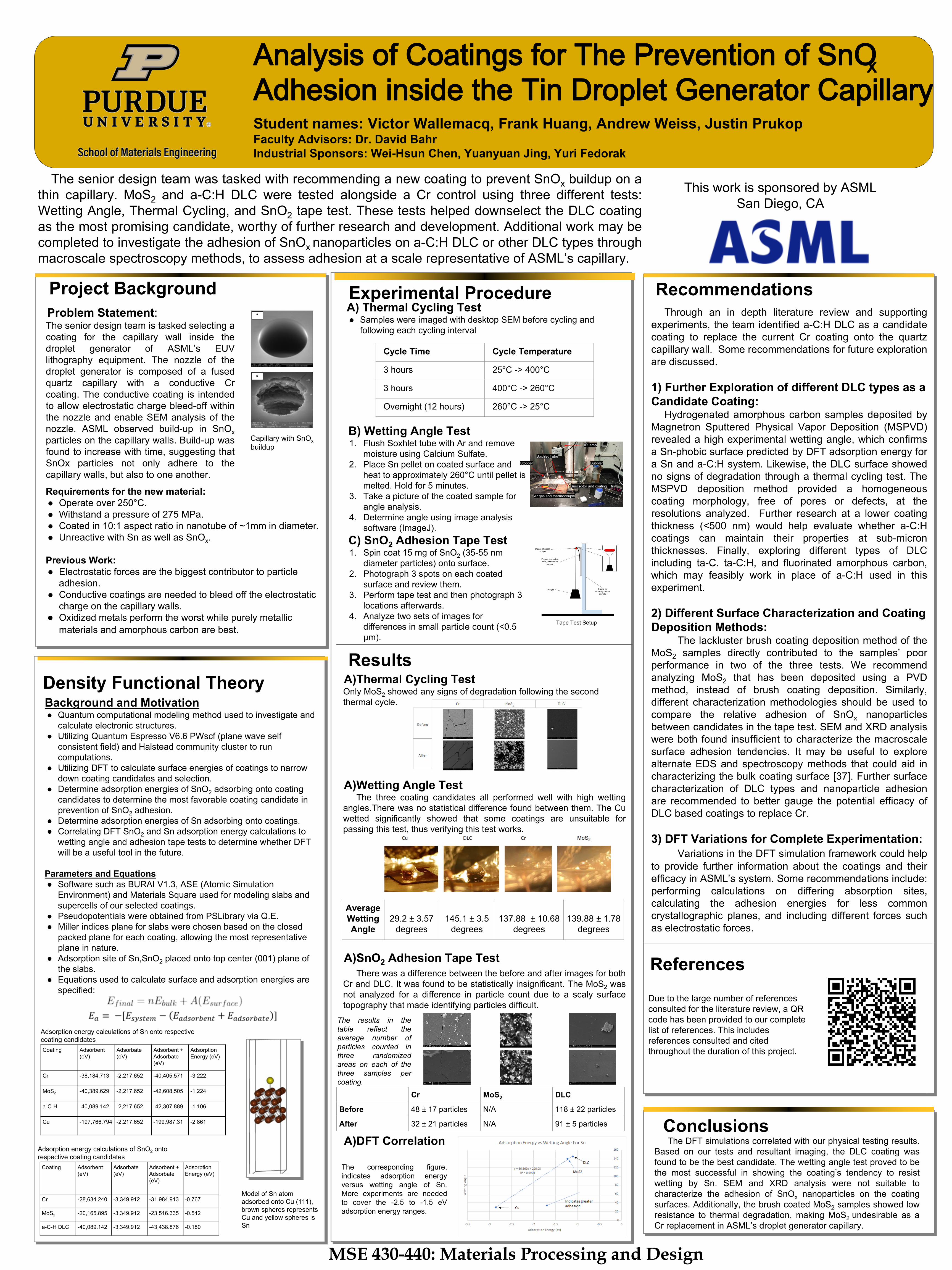
Analysis of Coatings for The Prevention of SnO x Adhesion inside the Tin Droplet Generator Capillary Student names: Victor Wallemacq, Frank Huang, Andrew Weiss, Justin Prukop Faculty Advisors: Dr. David Bahr Industrial Sponsors: Wei-Hsun Chen, Yuanyuan Jing, Yuri Fedorak Project Background The senior design team was tasked with recommending a new coating to prevent SnO x buildup on a thin capillary. MoS 2 and a-C:H DLC were tested alongside a Cr control using three different tests: Wetting Angle, Thermal Cycling, and SnO 2 tape test. These tests helped downselect the DLC coating as the most promising candidate, worthy of further research and development. Additional work may be completed to investigate the adhesion of SnO x nanoparticles on a-C:H DLC or other DLC types through macroscale spectroscopy methods, to assess adhesion at a scale representative of ASML’s capillary. Experimental Procedure Density Functional Theory Conclusions The DFT simulations correlated with our physical testing results. Based on our tests and resultant imaging, the DLC coating was found to be the best candidate. The wetting angle test proved to be the most successful in showing the coating’s tendency to resist wetting by Sn. SEM and XRD analysis were not suitable to characterize the adhesion of SnO x nanoparticles on the coating surfaces. Additionally, the brush coated MoS 2 samples showed low resistance to thermal degradation, making MoS 2 undesirable as a Cr replacement in ASML’s droplet generator capillary. Recommendations MSE 430-440: Materials Processing and Design This work is sponsored by ASML San Diego, CA Problem Statement: Through an in depth literature review and supporting experiments, the team identified a-C:H DLC as a candidate coating to replace the current Cr coating onto the quartz capillary wall. Some recommendations for future exploration are discussed. 1) Further Exploration of different DLC types as a Candidate Coating: Hydrogenated amorphous carbon samples deposited by Magnetron Sputtered Physical Vapor Deposition (MSPVD) revealed a high experimental wetting angle, which confirms a Sn-phobic surface predicted by DFT adsorption energy for a Sn and a-C:H system. Likewise, the DLC surface showed no signs of degradation through a thermal cycling test. The MSPVD deposition method provided a homogeneous coating morphology, free of pores or defects, at the resolutions analyzed. Further research at a lower coating thickness (<500 nm) would help evaluate whether a-C:H coatings can maintain their properties at sub-micron thicknesses. Finally, exploring different types of DLC including ta-C. ta-C:H, and fluorinated amorphous carbon, which may feasibly work in place of a-C:H used in this experiment. 2) Different Surface Characterization and Coating Deposition Methods: The lackluster brush coating deposition method of the MoS 2 samples directly contributed to the samples’ poor performance in two of the three tests. We recommend analyzing MoS 2 that has been deposited using a PVD method, instead of brush coating deposition. Similarly, different characterization methodologies should be used to compare the relative adhesion of SnO x nanoparticles between candidates in the tape test. SEM and XRD analysis were both found insufficient to characterize the macroscale surface adhesion tendencies. It may be useful to explore alternate EDS and spectroscopy methods that could aid in characterizing the bulk coating surface [37]. Further surface characterization of DLC types and nanoparticle adhesion are recommended to better gauge the potential efficacy of DLC based coatings to replace Cr. 3) DFT Variations for Complete Experimentation: Variations in the DFT simulation framework could help to provide further information about the coatings and their efficacy in ASML’s system. Some recommendations include: performing calculations on differing absorption sites, calculating the adhesion energies for less common crystallographic planes, and including different forces such as electrostatic forces. A) Thermal Cycling Test ● Samples were imaged with desktop SEM before cycling and following each cycling interval Background and Motivation ● Quantum computational modeling method used to investigate and calculate electronic structures. ● Utilizing Quantum Espresso V6.6 PWscf (plane wave self consistent field) and Halstead community cluster to run computations. ● Utilizing DFT to calculate surface energies of coatings to narrow down coating candidates and selection. ● Determine adsorption energies of SnO 2 adsorbing onto coating candidates to determine the most favorable coating candidate in prevention of SnO 2 adhesion. ● Determine adsorption energies of Sn adsorbing onto coatings. ● Correlating DFT SnO 2 and Sn adsorption energy calculations to wetting angle and adhesion tape tests to determine whether DFT will be a useful tool in the future. Parameters and Equations ● Software such as BURAI V1.3, ASE (Atomic Simulation Environment) and Materials Square used for modeling slabs and supercells of our selected coatings. ● Pseudopotentials were obtained from PSLibrary via Q.E. ● Miller indices plane for slabs were chosen based on the closed packed plane for each coating, allowing the most representative plane in nature. ● Adsorption site of Sn,SnO 2 placed onto top center (001) plane of the slabs. ● Equations used to calculate surface and adsorption energies are specified: References Due to the large number of references consulted for the literature review, a QR code has been provided to our complete list of references. This includes references consulted and cited throughout the duration of this project. Requirements for the new material: ● Operate over 250°C. ● Withstand a pressure of 275 MPa. ● Coated in 10:1 aspect ratio in nanotube of ~1mm in diameter. ● Unreactive with Sn as well as SnO x . Previous Work: ● Electrostatic forces are the biggest contributor to particle adhesion. ● Conductive coatings are needed to bleed off the electrostatic charge on the capillary walls. ● Oxidized metals perform the worst while purely metallic materials and amorphous carbon are best. Capillary with SnO x buildup The senior design team is tasked selecting a coating for the capillary wall inside the droplet generator of ASML’s EUV lithography equipment. The nozzle of the droplet generator is composed of a fused quartz capillary with a conductive Cr coating. The conductive coating is intended to allow electrostatic charge bleed-off within the nozzle and enable SEM analysis of the nozzle. ASML observed build-up in SnO x particles on the capillary walls. Build-up was found to increase with time, suggesting that SnOx particles not only adhere to the capillary walls, but also to one another. Results Cycle Time Cycle Temperature 3 hours 25°C -> 400°C 3 hours 400°C -> 260°C Overnight (12 hours) 260°C -> 25°C The corresponding figure, indicates adsorption energy versus wetting angle of Sn. More experiments are needed to cover the -2.5 to -1.5 eV adsorption energy ranges. A)Thermal Cycling Test Only MoS 2 showed any signs of degradation following the second thermal cycle. A)Wetting Angle Test The three coating candidates all performed well with high wetting angles.There was no statistical difference found between them. The Cu wetted significantly showed that some coatings are unsuitable for passing this test, thus verifying this test works. A)SnO 2 Adhesion Tape Test There was a difference between the before and after images for both Cr and DLC. It was found to be statistically insignificant. The MoS 2 was not analyzed for a difference in particle count due to a scaly surface topography that made identifying particles difficult. A)DFT Correlation B) Wetting Angle Test 1. Flush Soxhlet tube with Ar and remove moisture using Calcium Sulfate. 2. Place Sn pellet on coated surface and heat to approximately 260°C until pellet is melted. Hold for 5 minutes. 3. Take a picture of the coated sample for angle analysis. 4. Determine angle using image analysis software (ImageJ). C) SnO 2 Adhesion Tape Test 1. Spin coat 15 mg of SnO 2 (35-55 nm diameter particles) onto surface. 2. Photograph 3 spots on each coated surface and review them. 3. Perform tape test and then photograph 3 locations afterwards. 4. Analyze two sets of images for differences in small particle count (<0.5 µm). Soxhlet Tube Ar gas and thermocouple Bubbler IR lamp Susceptor and coating + tin Stopper Cr MoS 2 DLC Before 48 ± 17 particles N/A 118 ± 22 particles After 32 ± 21 particles N/A 91 ± 5 particles Average Wetting Angle 29.2 ± 3.57 degrees 145.1 ± 3.5 degrees 137.88 ± 10.68 degrees 139.88 ± 1.78 degrees The results in the table reflect the average number of particles counted in three randomized areas on each of the three samples per coating. Coating Adsorbent (eV) Adsorbate (eV) Adsorbent + Adsorbate (eV) Adsorption Energy (eV) Cr -38,184.713 -2,217.652 -40,405.571 -3.222 MoS 2 -40,389.629 -2,217.652 -42,608.505 -1.224 a-C-H -40,089.142 -2,217.652 -42,307.889 -1.106 Cu -197,766.794 -2,217.652 -199,987.31 -2.861 Coating Adsorbent (eV) Adsorbate (eV) Adsorbent + Adsorbate (eV) Adsorption Energy (eV) Cr -28,634.240 -3,349.912 -31,984.913 -0.767 MoS 2 -20,165.895 -3,349.912 -23,516.335 -0.542 a-C-H DLC -40,089.142 -3,349.912 -43,438.876 -0.180 Adsorption energy calculations of Sn onto respective coating candidates Adsorption energy calculations of SnO 2 onto respective coating candidates Model of Sn atom adsorbed onto Cu (111), brown spheres represents Cu and yellow spheres is Sn Tape Test Setup