+ All Categories
Home > Documents > ANALYSIS OF COMBUSTION PERFORMANCE AND EMISSION...

ANALYSIS OF COMBUSTION PERFORMANCE AND EMISSION...

Date post: 28-Aug-2018
Category:
Upload: vohuong
View: 220 times
Download: 0 times
Share this document with a friend
14
ANALYSIS OF COMBUSTION PERFORMANCE AND EMISSION OF EXTENDED EXPANSION CYCLE AND iEGR FOR LOW HEAT REJECTION TURBOCHARGED DIRECT INJECTION DIESEL ENGINES by Mohd F. SHABIR a , Baluchamy Rajendra PRASATH b* , and Packirisamy TAMILPORAI c a Department of Mechanical Engineering, Aalim Muhammad Salegh College of Engineering, Chennai, India b Department of Mechanical Engineering, Fatima Michael College of Engineering and Technology, Madura, India c Department of Mechanical Engineering, Anna University, Chennai, India Original scientific paper DOI: 10.2298/TSCI130707012S Increasing thermal efficiency in diesel engines through low heat rejection concept is a feasible technique. In low heat rejection engines the high heat evolution is achieved by insulating the combustion chamber surfaces and coolant side of the cylinder with partially stabilized zirconia of 0.5 mm thickness and the effective utili- zation of this heat depend on the engine design and operating conditions. To make the low heat rejection engines more suitable for automobile and stationary applica- tions, the extended expansion was introduced by modifying the inlet cam for late closing of intake valve through Miller's cycle for extended expansion. Through the extended expansion concept the actual work done increases, exhaust blow-down loss reduced and the thermal efficiency of the low heat rejection engine is improved. In low heat rejection engines, the formation of nitric oxide is more, to reduce the ni- tric oxide emission, the internal exhaust gas re-circulation is incorporated using modified exhaust cam with secondary lobe. Modifications of gas exchange with in- ternal exhaust gas re-circulation resulted in decrease in nitric oxide emissions. In this work, the parametric studies were carried out both theoretically and experi- mentally. The combustion, performance and emission parameters were studied and were found to be satisfactory. Key words: low heat rejection, Miller cycle, exhaust gas re-circulation, oxides of nitrogen Introduction Low heat rejection (LHR) is one of the energy conservation concepts used in turbo- charged diesel engines which results in low fuel consumption for the same power output, thereby reducing its size and aids to eliminate the cooling system. The diesel engine with its combustion chamber walls are insulated by heat flow resistant coating is referred to as LHR en- gine. The heat resistant coating reduces the heat transfer to the coolant system and improves the thermal efficiency by increasing the energy availability in the exhaust [1-7]. Turbocharging can prevent the deterioration in volumetric efficiency of the LHR engine and that there can be more effective utilization of the exhaust gas energy [8-10]. The engine with higher expansion ratio than compression ratio is referred to as ex- tended expanded engine (EEE) [11]. The fundamental aim of extended expansion concept is to Shabir, M. F., et al.: Analysis of Combustion Performance and Emission of .... THERMAL SCIENCE: Year 2014, Vol. 18, No. 1, pp. 129-142 129 * Corresponding author: e-mail: [email protected]
Transcript

ANALYSIS OF COMBUSTION PERFORMANCE AND EMISSION OFEXTENDED EXPANSION CYCLE AND iEGR FOR LOW HEAT

REJECTION TURBOCHARGED DIRECT INJECTION DIESEL ENGINES

by

Mohd F. SHABIR a, Baluchamy Rajendra PRASATH b*,and Packirisamy TAMILPORAI c

a Department of Mechanical Engineering, Aalim Muhammad Salegh College ofEngineering, Chennai, India

b Department of Mechanical Engineering, Fatima Michael College of Engineering andTechnology, Madura, India

c Department of Mechanical Engineering, Anna University, Chennai, India

Original scientific paperDOI: 10.2298/TSCI130707012S

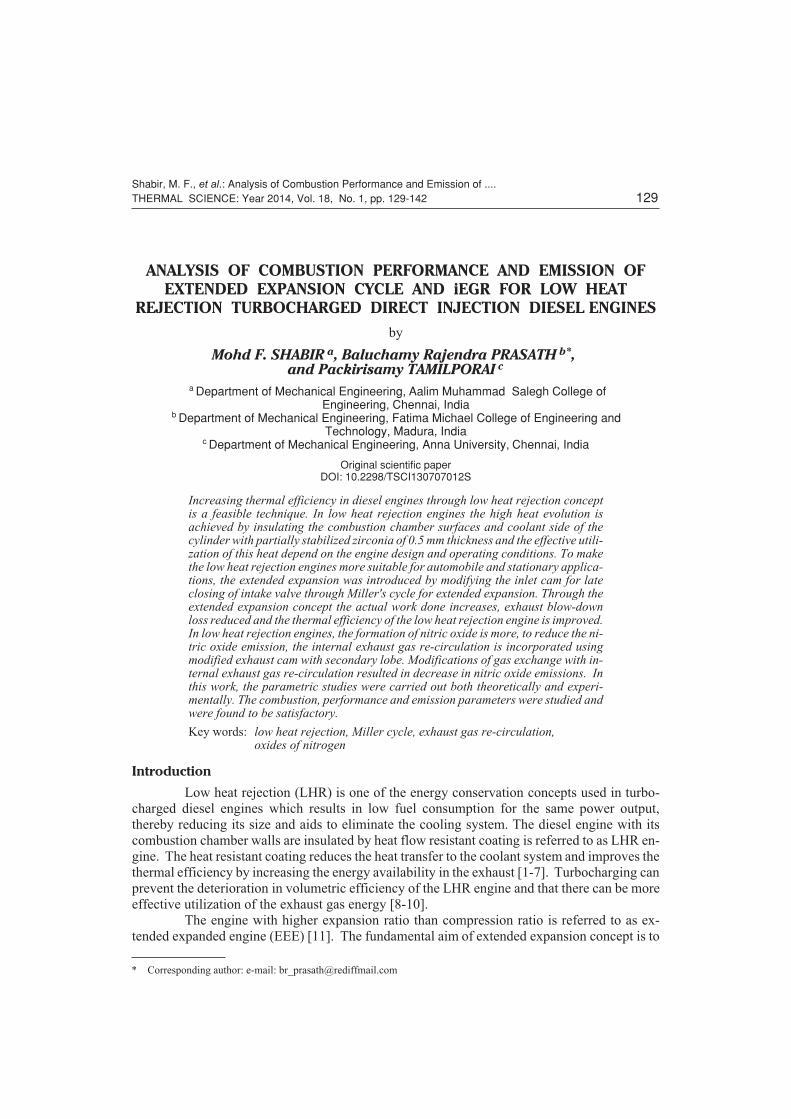
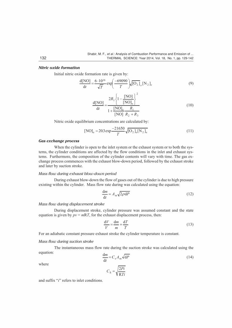
Increasing thermal efficiency in diesel engines through low heat rejection conceptis a feasible technique. In low heat rejection engines the high heat evolution isachieved by insulating the combustion chamber surfaces and coolant side of thecylinder with partially stabilized zirconia of 0.5 mm thickness and the effective utili-zation of this heat depend on the engine design and operating conditions. To makethe low heat rejection engines more suitable for automobile and stationary applica-tions, the extended expansion was introduced by modifying the inlet cam for lateclosing of intake valve through Miller's cycle for extended expansion. Through theextended expansion concept the actual work done increases, exhaust blow-downloss reduced and the thermal efficiency of the low heat rejection engine is improved.In low heat rejection engines, the formation of nitric oxide is more, to reduce the ni-tric oxide emission, the internal exhaust gas re-circulation is incorporated usingmodified exhaust cam with secondary lobe. Modifications of gas exchange with in-ternal exhaust gas re-circulation resulted in decrease in nitric oxide emissions. Inthis work, the parametric studies were carried out both theoretically and experi-mentally. The combustion, performance and emission parameters were studied andwere found to be satisfactory.

Key words: low heat rejection, Miller cycle, exhaust gas re-circulation,oxides of nitrogen

Introduction

Low heat rejection (LHR) is one of the energy conservation concepts used in turbo-

charged diesel engines which results in low fuel consumption for the same power output,

thereby reducing its size and aids to eliminate the cooling system. The diesel engine with its

combustion chamber walls are insulated by heat flow resistant coating is referred to as LHR en-

gine. The heat resistant coating reduces the heat transfer to the coolant system and improves the

thermal efficiency by increasing the energy availability in the exhaust [1-7]. Turbocharging can

prevent the deterioration in volumetric efficiency of the LHR engine and that there can be more

effective utilization of the exhaust gas energy [8-10].

The engine with higher expansion ratio than compression ratio is referred to as ex-

tended expanded engine (EEE) [11]. The fundamental aim of extended expansion concept is to

Shabir, M. F., et al.: Analysis of Combustion Performance and Emission of ....THERMAL SCIENCE: Year 2014, Vol. 18, No. 1, pp. 129-142 129

* Corresponding author: e-mail: [email protected]

achieve higher work done by decreasing the compression work done, which in turn leads to

higher thermal efficiency. This concept is compatible with the application of turbocharger and

LHR engine. The short compression stroke is achieved by closing the intake valve early in the

cycle before bottom dead centre (BDC) or by closing it late after BDC. The advantages of an ex-

tended expansion cycle includes, reduced specific fuel consumption and increased power output

without increasing the cylinder peak pressure [12, 13]. LHR engine with exhaust gas re-circula-

tion (EGR) gives good agreement in view of performance and emission characteristics [14, 15].

Also, the extended expansion cycle has the potential for NOx emission control due to lower cyl-

inder gas temperature but better results can be obtained by reducing intake oxygen concentra-

tion with EGR [16-18]. Internal EGR (iEGR) can be achieved by delaying the opening of ex-

haust valve, early closing of the exhaust valve and secondary opening of the exhaust valve

during the intake stroke [19, 20].

In the present work, the combined potential of extended expansion cycle and iEGR in

LHR turbocharged engine has been assessed. As a part of the investigation, initially a simulation

program was run to optimize the inlet valve closing timing and percentage of iEGR for LHR

turbocharged engine for better performance and lower NOx emission levels. Finally, experi-

mental investigations were performed to validate the predicted values of combustion, heat trans-

fer process, performance and emission characteristics.

Computer simulation using combustion,

gas heat transfer and wall heat transfer models

The combustion model is based on the Whitehouse and Way model [21] through

which the preparation rate and reaction rate were estimated and subsequently the heat release

was calculated [22]. Annand's combined heat transfer model [23, 24] was used to estimate the

total heat transfer. The Wall heat transfer model is based on the thermal network analogy pro-

posed by Amann [25] and Miyairi [26]. The nitric oxide concentration was obtained using mod-

ified Zeldovich mechanism through equilibrium reaction kinetics [27]. Using the first law of

thermodynamics along with various energy and enthalpy coefficients the cylinder pressure, heat

release and temperatures are calculated [28].

In this simulation during the start of compression, the mole of different species that are

considered to be present includes oxygen, nitrogen from intake and carbon dioxide. Water (gas-

eous), nitrogen and oxygen from the residual gases.

Heat transfer

The gas-wall heat transfer is found out using Annand's convective heat transfer model.

A wall heat transfer model is used to find out the instantaneous wall temperature. First term of

this equation shows that Prandtl number for the gases forming the cylinder contents will be ap-

proximately constant at a value 0.7, claims that Reynolds number is the major parameter affect-

ing convection. The second is a straightforward radiation term assuming gray body radiation:

d

dC W C W

Q

tak

dT T c T T

b

� � � �Re

( ) ( )4 4 (1)

Wall heat transfer model

This model is used to find out conductive heat transfer through cylinder to the coolant

and thereby to find instantaneous wall temperature. Initial temperature is found out using the

following expression:

Shabir, M. F., et al.: Analysis of Combustion Performance and Emission of ...130 THERMAL SCIENCE: Year 2014, Vol. 18, No. 1, pp. 129-142

T TQ

h r lwi g

w

g

� ��

��

2 1pW (2)

and

QT T

Rw

g w�

��

���

(3)

The total conductive resistance offered by the cylinder liner, piston rings, cylinder

head, ceramic coating and piston for the heat transfer from cylinder gases to coolant is calcu-

lated using the expression:

Rh r l h r l

r

r

k l�

��

��

���

1

2

1

2 21 3

2

1

1 1g c

ep p p

log

����

����

log

log

e

c c

e

r

r

k l

3

4

5

9

2

3

p

r

r

k k kr r

e

s p2 2

7

8 7

p pl

r

r

l

r

s

����

����

�log2 7pr Tp

��

(4)

Mass of fuel injected

Considering that nozzle open area is constant during the injection period, mass of the

fuel injected for each crank angle is calculated using the following expression:

m C A PN

f D n f��

��

2

360r

qD

D(5)

Preparation rate

The preparation rate depends on the mass of fuel injected in the cylinder upto the time

of calculation and part of the fuel still available for preparation with respect to partial pressure of

oxygen. The preparation rate was calculated using the following equation [21]:

P KM M Pi

xr

( )ux

OL

2

� �1 (6)

K N M P h d� � � �0085 0 414 1 414 1 414 1 414 3 644. . . . . .i n (7)

Reaction rate

The reaction rate depends on the delay period, velocity of gas molecules, oxygen den-

sity and mass of unburnt fuel. The effect of delay period was evaluated by introducing a chemi-

cal reaction rate using an Arrhenius type expression. Assuming that the velocity of the gas mol-

ecule is proportional to the square root of the temperature, the density of oxygen is proportional

to the partial pressure divided by the temperature, the unburnt fuel is given by �(Pr(q+1) – Rr(q))dq.

The reaction rate was calculated using the following expression [21]:

RK P

N TP R

act

Tr

O

r re d( ) ( ) ( )( )q q q q�

���

� �1 12 (8)

where K�is the reaction rate constant (87·1010 K1/2/bar·s) and act – the activation energy for the

total species (1.65·104 K).

Shabir, M. F., et al.: Analysis of Combustion Performance and Emission of ....THERMAL SCIENCE: Year 2014, Vol. 18, No. 1, pp. 129-142 131

Nitric oxide formation

Initial nitric oxide formation rate is given by:

d NO

dO N

[ ]exp [ ] [ ]

t T T e e� ��

��

6 10 6909016

2 2 (9)

d NO

d

NO

NO

NO

NO

e

e

[ ]

[ ]

[ ]

[ ]

[ ]

t

R

R

R R

����

���

��

2 1

1

1

2

1

2 3

(10)

Nitric oxide equilibrium concentrations are calculated by:

[ ] . exp [ ] [ ]NO O Ne e e��

20321650

2 2T

(11)

Gas exchange process

When the cylinder is open to the inlet system or the exhaust system or to both the sys-

tems, the cylinder conditions are affected by the flow conditions in the inlet and exhaust sys-

tems. Furthermore, the composition of the cylinder contents will vary with time. The gas ex-

change process commences with the exhaust blow-down period, followed by the exhaust stroke

and later by suction stroke.

Mass flow during exhaust blow-down period

During exhaust blow-down the flow of gases out of the cylinder is due to high pressure

existing within the cylinder. Mass flow rate during was calculated using the equation:

d

ddm

m

tA P� 2r (12)

Mass flow during displacement stroke

During displacement stroke, cylinder pressure was assumed constant and the state

equation is given by pv = mRT, for the exhaust displacement process, then:

d d dV

V

m

m

T

T� � (13)

For an adiabatic constant pressure exhaust stroke the cylinder temperature is constant.

Mass flow during suction stroke

The instantaneous mass flow rate during the suction stroke was calculated using the

equation:d

dds m

m

tC A P� (14)

where

CPi

TiS

R�

2

and suffix “i” refers to inlet conditions.

Shabir, M. F., et al.: Analysis of Combustion Performance and Emission of ...132 THERMAL SCIENCE: Year 2014, Vol. 18, No. 1, pp. 129-142

Test engine development

Modification of conventional turbocharged engine

to LHR turbocharged engine

The conventional turbocharged engine was modified to LHR turbocharged engine

through plasma spray technique. The piston crown, cylinder liner outside, cylinder head and

valves are applied with partially stabilized zirconia coating of 0.5 mm thickness. Figures 1 and

2 show the photographic view of ceramic coated components.

Modification of LHR turbocharged engine to LHR

turbocharged extended expansion engine

The LHR turbocharged engine was later modified to LHR turbocharged extended ex-

pansion engine by late closing of the intake valve. The intake valve closes conventionally at 45º

aBDC (IVC at 45º aBDC), which was later modified to close at 60º aBDC (IVC at 60º aBDC).

By late closing of the intake valve by 15º crank angle the LHR turbocharged was modified to

LHR turbocharged extended expansion engine. By late closing of the intake valve the effective

compression ratio was reduced from 14.18 to 12.85. Figures 3 and 4 show the valve timing dia-

gram of the conventional turbocharged engine, LHR turbocharged extended expansion engine

and figs. 5 and 6 shows the intake cam profile for the conventional turbocharged engine and

modified intake cam profile for the LHR turbocharged extended expansion engine.

Shabir, M. F., et al.: Analysis of Combustion Performance and Emission of ....THERMAL SCIENCE: Year 2014, Vol. 18, No. 1, pp. 129-142 133

Figure 1. Photographic view of piston top withceramic coating

Figure 2. Photographic view of cylinder headwith ceramic coating

Figure 3. Conventionalengine valve timingdiagram

Figure 4. Extendedexpansion engine valvetiming

Figure 5. Conventionalintake cam

Figure 6. Modifiedintake cam

Modification of LHR turbocharged extended expansion engine

to LHR turbocharged extended expansion engine with internal

exhaust gas re-circulation

The LHR turbocharged extended expan-

sion engine was later modified to LHR

turbocharged extended expansion engine

with iEGR by secondary opening of the ex-

haust valve during suction stroke. The sec-

ondary exhaust valve opening takes place at

65º aTDC and closes at 65º bBDC. The total

secondary exhaust valve opening duration is

50º crank angle (CA). The secondary ex-

haust valve lift is taken as 3 mm [12]. The

EGR rate was determined on the basis of the

engine output power with respect to the ex-

haust valve lift and valve opening time

through the simulation. With this strategy,

iEGR levels of 9 to 10% have been attained in the whole engine

range. Figure 7 show the valve timing diagram for LHR turbo-

charged extended expansion engine with iEGR. Figures 8 and 9

show the conventional exhaust cam profile and modified exhaust

cam profile.

Experimental set-up and procedure

The experimental set-up and the specifications of the test en-

gine are shown in fig. 10 and tab. 1, respectively. The crank an-

gle pulse generating system consisting of a pulse-generating

wheel, intended to make a pulse for every 10

degrees of crank rotation is attached to the

front end of the crankshaft of the engine. To

distinguish the TDC and BDC position, three

teeth at 5 degree gaps were provided diametri-

cally opposite on the wheel. All other teeth

were at 10 degree interval. A magnetic pick

up was mounted near the pulse-generating

wheel to sense the crank angle position. On

rotation of the pulse generating wheel the sig-

nal generated is fed into one of the channel to

the storage oscilloscope for storing and subse-

quently for transferring it to a personal com-

puter for plotting the cylinder pressure with

respect to crank angle. A piezo electric pres-

sure transducer fitted with an adopter was

screwed onto a tapped hole on the cylinder

head. The piezo electric crystal produces an electric charge proportional to the pressure inside

the combustion chamber, and this electric charge is fed to a charge amplifier for conditioning

Shabir, M. F., et al.: Analysis of Combustion Performance and Emission of ...134 THERMAL SCIENCE: Year 2014, Vol. 18, No. 1, pp. 129-142

Figure 7. Turbochargedextended expansionengine with iEGR valvetiming diagram

Figure 8. Conventionalexhaust cam

Figure 9. Modified exhaustcam with secondary lobe

Figure 10. Experimental set-up1 – engine, 2 – eddy current dynamometer, 3 – fuelpump, 4 – radiator, 5 – air surge tank, 6 –compressorr, 7 – inlet line, 8 – exhaust line, 9 –turbine, 10 – exhaust gas analyzer, 11 – fuel tank, 12 –crank angle encoder, 13 – piezo electric transducer,14 – charge amplifier, 15 – digital signal explorer

and conversion into equivalent

mechanical units. The output

signal from the charge amplifier

is fed into one channel of the

storage oscilloscope for storing

and transfers it to a personal

computer for plotting.

The experimental engine's

components such as cylinder

head with valves, outer surface

of the cylinder liner and the pis-

ton top surface were coated with

partially stabilized zirconia of

0.5 mm thickness. After fitting

the ceramic-coated components in the engine the experiments were carried out under identical

conditions. The modified camshaft for extended expansion was then fitted in coated engine and

the experiments were carried out under identical conditions. The modified camshaft for extended

expansion with internal exhaust gas re-circulation was then fitted and the experiments were car-

ried out under identical conditions. Under identical operating conditions the experiment was re-

peated for three times and precautionary steps have been taken while conducting the experiments.

An uncertainty analysis was performed using the method described by Holman [29].

Results and discussion

Tests were conducted under the following operating conditions of the engine such as

(1) Conventional – Conventional turbocharged engine (IVC at 45° aBDC), (2) LHR – LHR

turbocharged engine (IVC at 45° aBDC), (3) LHR (EEE) – LHR turbocharged extended expan-

sion engine (IVC at 60° aBDC), and (4) LHR (EEE with iEGR) – LHR turbocharged extended

expansion engine with iEGR (IVC at 60° aBDC with 10% EGR). The results are analysed and

presented for the same fuel supplied (0.06945 g/cylinder/cycle) at 1500 rpm.

Comparison of cylinder pressure

Figure 11 shows the comparison between simulated and experimental values of cylin-

der peak pressure for conventional turbocharged engine, LHR turbocharged engine, LHR turbo-

charged extended expansion engine, and LHR turbocharged extended expansion engine with

iEGR. The prediction shows that, the cylinder peak pressure are higher by 4.52% and 1.79% for

LHR turbocharged engine and LHR turbocharged extended expansion engine, respectively, and

is lower by 0.83% for LHR turbocharged extended expansion with iEGR when compared to

conventional turbocharged engine.

The increase in cylinder peak pressure in the case of LHR turbocharged engine may be

due to increased boost pressure and air density. Along with the effect of boost pressure, the higher

heat retainment inside the combustion chamber with higher engine operating temperature en-

hances the preparation and reaction rate resulting in increased cylinder peak pressure. The cylin-

der peak pressure of LHR turbocharged extended expansion engine is comparatively lesser than

the LHR turbocharged engine. The reason for this may be due to, reduced inlet pressure and de-

crease in preparation and reaction rate because of lower compression temperature caused by re-

duction in effective compression ratio. The cylinder peak pressure of LHR turbocharged extended

expansion engine with internal exhaust gas recirculation is lower than the conventional turbo-

Shabir, M. F., et al.: Analysis of Combustion Performance and Emission of ....THERMAL SCIENCE: Year 2014, Vol. 18, No. 1, pp. 129-142 135

Table 1. Specifications of the engine

Type4 Cylinder, 4 stroke, water cooled

turbocharged DI diesel engine

Bore 111.1 mm

Stroke 127.0 mm

Connecting rod length 251.0 mm

Nominal compression ratio 16 : 1

Rated power output 55.2 kW at 1500 rpm

Fuel injection pressure 210 bar

Nozzle hole diameter 0.26 mm

No. of nozzle holes 3

charged engine, but it is in the operating performance limit for effective work done. The re-circu-

lation of exhaust gas (acts as a heat sink) reduces the time availability for the mixing of the fuel

with available oxygen concentration and hence the mixing and preparation is reduced. This varia-

tion in charge mixing and preparation rate and reduction in compression ratio results in reduction

in pressure in LHR turbocharged extended expansion engine with iEGR.

Comparison of cylinder mean temperature

Cylinder mean temperature is the cylinder area averaged temperature which is lower

than the peak flame temperature and which is essentially responsible for the work done. Figure

12 shows the comparison of cylinder mean temperature for conventional turbocharged engine,

LHR turbocharged engine, LHR turbocharged

extended expansion engine, and LHR turbo-

charged extended expansion engine with iEGR.

The percentage increase in cylinder mean temper-

ature for LHR turbocharged engine, LHR turbo-

charged extended expansion engine, and LHR

turbocharged extended expansion with iEGR are

6.03%, 4.48% and 3.75%, respectively, when

compared to conventional turbocharged engine.

The trend shows that LHR turbocharged engines

are operating at higher cylinder mean tempera-

ture. The higher cylinder mean temperature

achieved is mainly attributed to insulation coat-

ings applied to combustion chamber walls.

Shabir, M. F., et al.: Analysis of Combustion Performance and Emission of ...136 THERMAL SCIENCE: Year 2014, Vol. 18, No. 1, pp. 129-142

Figure 11. Comparison of cylinder pressure for different operating conditions; (a) conventionalturbocharged engine, (b) LHR turbocharged engine, (c) LHR turbocharged extended expansion engine,(d) LHR turbocharged extended expansion engine with iEGR (for color image see journal web site)

Figure 12. Comparison of cylinder meantemperature for different operating conditions(for color image see journal web site)

In the case of LHR turbocharged extended expansion engine due to reduction in effec-

tive compression ratio, the compression temperature decreases leading to lesser rate of heat re-

lease, thereby decreasing the heat content inside the cylinder which finally results in lower cyl-

inder mean temperature. In the case of LHR turbocharged extended expansion engine with

iEGR, because of the re-circulation of the exhaust gases mainly CO2 and H2O (gaseous) the spe-

cific heat of the cylinder gases increases, which decreases the cylinder mean temperature when

compared to the LHR turbocharged extended expansion engine. The amount of exhaust gas

re-circulated was small in portion. If higher percentages of exhaust gas is re-circulated the en-

gine performance gets affected, so with a restriction of 10% of EGR was assumed in this work to

avoid the NOx formation which results in only a small effect with the variation in the cylinder

mean temperature.

Comparison of rate of heat release

Figure 13 shows the comparison of rate of heat release for Conventional turbocharged

engine, LHR turbocharged engine, LHR turbocharged extended expansion engine and LHR

turbocharged extended expansion engine with iEGR. The prediction shows that the peak rate of

heat releases during premixed combustion are lower by 31.43% and 8.93% for LHR turbo-

charged engine and LHR turbocharged extended expansion engine respectively and is higher by

0.84% for LHR turbocharged extended expansion with iEGR when compared to conventional

turbocharged engine. The experimental values of peak rate of heat release when compared to

theoretical predictions are lesser by 6.14%, 6.71%, 5.32%, and 6.42% for Conventional turbo-

charged engine, LHR turbocharged engine, LHR turbocharged extended expansion engine and

LHR turbocharged extended expansion engine with iEGR, respectively.

The decrease in peak rate of heat release during premixed combustion in the case of

LHR turbocharged engine compared to Conventional turbocharged engine is due to decrease in

Shabir, M. F., et al.: Analysis of Combustion Performance and Emission of ....THERMAL SCIENCE: Year 2014, Vol. 18, No. 1, pp. 129-142 137

Figure 13. Comparison of rate of heat release for different operating conditions; (a) conventionalturbocharged engine, (b) LHR turbocharged engine, (c) LHR turbocharged extended expansion engine,(d) LHR turbocharged extended expansion engine (for color image see journal web site)

time available for charge mixing and preparation because of higher heat retainment inside the

combustion chamber leading to instantaneous burning of fuel at much elevated temperatures.

The increase in peak heat release during premixed combustion in the case of LHR extended ex-

pansion engine is due to lower preparation rate along with proportionate amount of charge accu-

mulation and its spontaneous burning. As in the case of LHR extended expansion engine with

iEGR the above charge accumulation may be further more increased and burnt spontaneously

which leads to further increase in peak rate of heat release.

Comparison of cumulative work done

Figure 14 shows the comparison of cumulative work done for conventional turbo-

charged engine, LHR turbocharged engine, LHR turbocharged extended expansion engine, and

LHR turbocharged extended expansion engine with iEGR. The prediction shows that the cumu-

lative work done for LHR turbocharged engine and LHR turbocharged extended expansion en-

gine and LHR turbocharged extended expansion with iEGR is higher by 5.42%, 5.82%, and

3.35%, respectively, when compared to conventional turbocharged engine. The increase in the

cumulative work done in the case of LHR turbocharged extended expansion engine is mainly at-

tributed to the decrease in compression work done. The compression work done reduces by

8.01% for LHR turbocharged extended expansion engine when compared to LHR turbocharged

engine. The cumulative work done of LHR

turbocharged extended expansion engine with

iEGR is lesser than the LHR turbocharged ex-

tended expansion engine. This may be due to

lower cylinder peak pressure but it is in the op-

erating performance limit for effective work

done.

Brake thermal efficiency

Figure 15 shows the variation of brake ther-

mal efficiency with speed. The brake thermal

efficiency increases by 1.71% to 4.58% for

LHR turbocharged engine, 6.26% to 9.07% for

LHR turbocharged extended expansion engine

and 2.73% to 4.90% for LHR turbocharged ex-

tended expansion engine with iEGR when com-

pared to conventional turbocharged engine for

the speed range of 1000 rpm to 1500 rpm. Ex-

perimental results are also in close agreement

with the simulation results and the correspond-

ing values are 2.80% to 5.74%, 8.03% to

11.88%, and 3.55% to 6.33%, respectively. In

the case of LHR turbocharged extended expan-

sion engine the brake thermal efficiency in-

creases compared to conventional turbocharged

engine due to decrease in heat transfer and com-

pression work done caused by ceramic coating

and late closing of the intake valve respectively.

In the case of LHR extended expansion engine

Shabir, M. F., et al.: Analysis of Combustion Performance and Emission of ...138 THERMAL SCIENCE: Year 2014, Vol. 18, No. 1, pp. 129-142

Figure 14. Comparison of work done fordifferent operating conditions(for color image see journal web site)

Figure 15. Variation of brake thermal efficiencywith respect to engine speed(for color image see journal web site)

with iEGR the brake thermal efficiency decreases when compared to LHR turbocharged ex-

tended expansion engine because of the replacement of fresh charge with EGR, which decreases

the cylinder peak pressure, resulting in decrease in cumulative work done. But the brake ther-

mal efficiency of LHR turbocharged extended expansion engine with iEGR is higher than the

conventional turbocharged engine.

NOx

emissions

Figure 16 shows the comparison of NOx

emissions with speed. The trend shows that the

NOx emission increases with increasing speed

for all operating conditions. The NOx emissions

increases by about 50.18% and 25.33% for LHR

turbocharged engine and LHR turbocharged ex-

tended expansion, respectively, and reduces by

7.03% for LHR turbocharged extended expan-

sion engine with iEGR when compared to con-

ventional turbocharged engine at 1500 rpm. In

low heat rejection engines due to higher peak

flame temperature dissociation of N2 and O2

takes place within a short period of time, which

increases the formation of NOx emission. The decrease in NOx emissions in LHR turbocharged

extended expansion engine with iEGR is more significant due to its lower operating temperature

and lesser oxygen concentration. The results of the computations show the expected behaviour

and are qualitatively and quantitatively in excellent agreement with the experiment.

Hydrocarbon emissions

Figure 17 shows the comparison of hydrocar-

bon emissions with speed. The hydrocarbon

emissions reduces by 32.45% and 17.9% for

LHR turbocharged engine and LHR turbo-

charged extended expansion engine, respec-

tively, and increases by 2.06% for LHR turbo-

charged extended expansion engine with iEGR

when compared to conventional turbocharged

engine at 1500 rpm. Experimental results are

also in close agreement with the simulation re-

sults and the corresponding values are 21.54%,

14.89% and 3.24%, respectively.

Conclusions

After a detailed analysis of the conventional turbocharged engine, LHR turbocharged

engine, LHR turbocharged extended expansion engine, and LHR turbocharged extended expan-

sion engine with iEGR, focusing on combustion, performance, and emissions the following con-

clusions were made.

� The in-cylinder peak pressure for LHR turbocharged extended expansion engine with iEGR

is lower by 0.83% when compared to conventional turbocharged engine, but it is in the

operating performance limit for effective work done.

Shabir, M. F., et al.: Analysis of Combustion Performance and Emission of ....THERMAL SCIENCE: Year 2014, Vol. 18, No. 1, pp. 129-142 139

Figure 16. Variation of NOx emissions withrespect to engine speed(for color image see journal web site)

Figure 17. Variation of hydrocarbon emissionswith respect to engine speed(for color image see journal web site)

� The cylinder mean temperature for LHR turbocharged extended expansion engine with

iEGR is higher by 3.75% when compared to conventional turbocharged engine. The high

temperature achieved is mainly attributed to insulation coating applied to cylinder

components.

� The rate of heat release during premixed combustion is higher by 0.84% for LHR

turbocharged extended expansion with iEGR when compared to conventional turbocharged

engine may be due to increase in ignition delay period because of the lesser preparation rate

caused by reduced oxygen concentration.

� The cumulative work done is higher by 3.35% for LHR turbocharged extended expansion

engine with iEGR when compared to conventional turbocharged engine because of lower

compression work done.

� NOx emission increases with increasing speed for all operating conditions. It decreases by

7.03% for LHR turbocharged extended expansion engine with iEGR when compared to

conventional turbocharged engine at 1500 rpm.

� The hydrocarbon emissions slightly increases by 2.06% for LHR turbocharged extended

expansion engine with iEGR when compared to conventional turbocharged engine.

The comparison of predicted and measured data demonstrated reasonable quantitative

agreement between them. Additional effort is required to assess the fidelity of each model across

a wider range of operating conditions and engine types.

References

[1] Baluswamy, N., Spatial and Temporal Distribution of Gaseous Pollutants in a Diesel Engine CombustionChamber, Ph. D. thesis, Institute of Sc. Tech., University of Manchester, Manchester, UK, 1976

Shabir, M. F., et al.: Analysis of Combustion Performance and Emission of ...140 THERMAL SCIENCE: Year 2014, Vol. 18, No. 1, pp. 129-142

Nomenclature

Am – minimum valve flow area, [m2]An – nozzle hole area, [m2]a, b, – Annand's convective heat transferc, d – equation co-efficientCd – coefficient of discharge for injector nozzleCs – parameter for mass flow through the

– intake valvedn – nozzle hole diameter, [mm]h – number of holes in injector nozzlehc – wall – coolant heat transfer coefficient,

– [kJm–2h–1K–1]hg – gas wall heat transfer coefficient,

– [kJm–2h–1K–1]K – constant in preparation rate equationk – thermal conductivity, [Wm–1K–1]kc – thermal conductivity of ceramic material,

– [WmK–1]kl – thermal conductivity of liner material,

– [WmK–1]kp – thermal conductivity of piston material,

– [WmK–1]kr – thermal conductivity of ring material,

– [WmK–1]L – index constant in preparation rate

– equationl – stroke length, [m]

ll – cylinder length, [m]lC – connecting rod length, [m]ls – skirt length, [m]M – mass of fuel injected,

– [grams/cycle/cylinder]Mi – total mass of fuel injected, [kg]Mu – mass of fuel in cylinder and unprepared,

– [kg]mf – mass of fuel injected during injection

– period for each cylinder, [kg]Pi – injection period, [degree crank angle]Pr – preparation rate,

– [kg per degree crank angle]

Dp – pressure drop across the nozzle, [bar]Q – total heat transfer, [kJ]Qw – wall heat transfer, [kJ]Rr – reaction rate, [kg per degree crank angle]r1, r2, r3,– radii of the composite cylinder wall withr4, r5, r6,– respect to cylinder axis, [m]r7, r8, r9

Tc – cylinder mean temperature, [K]Tg – gas temperature, [K]Tp – thickness of the piston crown, [m]Tw – cylinder wall temperature, [K]x – index constant in preparation rate

– equation

[2] Buyukkaya, E., et al., Effects of Thermal Barrier Coating on Gas Emissions and Performance of a LHREngine with Different Injection Timings and Valve Adjustments, Energy Conversion and Management,47 (2006), 9-10, pp. 1298-1310

[3] Parlak, A., et al., The effects of Injection Timing on NOx Emissions of a Low Heat Rejection Indirect Die-sel Injection Engine, Applied Thermal Engineering, 25 (2005), 17-18, pp. 3042-3052

[4] Kesava Reddy, Ch., et al., Performance Evaluation of a Low-Grade Low-Heat-Rejection Diesel Enginewith Crude Pongamia Oil, ISRN Renewable Energy, 2012 (2012), ID 489605

[5] Rajendra Prasath, B., et al., Two-Zone Modeling of Diesel/Biodiesel Blended Fuel Operated CeramicCoated Direct Injection Diesel Engine, International Journal of Energy and Environment, 1 (2010), 6, pp.1039-1056

[6] Mathews, P. K., Deepanraj, B., Experimental Investigation on Performance and Emission Characteristicsof Low Heat Rejection Diesel Engine with Ethanol as Fuel, American Journal of Applied Sciences, 8(2011), 4, pp. 348-354

[7] Shrirao, P. N., Pawar, A. N., Evaluation of Performance and Emission Characteristics of TurbochargedDiesel Engine with Mullite as Thermal Barrier Coating, International Journal of Engineering and Tech-nology, 3 (2011), 3, pp. 256-262

[8] Tamil Porai, P., et al., Simulation and Analysis of Combustion and Heat Transfer in Low-Heat-RejectionDiesel Engine Using Two-Zone Combustion Model and Different Heat Transfer Models, SAE technicalpaper 2003-01-1067, 2003

[9] Parlak, A., et al., The Effect of Thermal Barrier Coating on a Turbo-Charged Diesel Engine Performanceand Exergy Potential of the Exhaust Gas, Energy Conversion and Management, 46 (2005), 3, pp. 489-499

[10] Giakoumis, E. G., Cylinder Wall Insulation Effects on the First and Second-Law Balances of a Turbo-charged Diesel Engine Operating under Transient Load Conditions, Energy Conversion and Management48 (2007), 11, pp. 2925-2933

[11] Kentfield, J. A. C., Diesel Engines with Extended Expansion Strokes, SAE paper 891866, 1989[12] Kamo, R., et al., Emissions Comparisons of an Insulated Turbocharged Multi-Cylinder Miller Cycle Die-

sel Engine, SAE paper 980888, 1998[13] Mavinahally, N., Kamo, R., Insulated Miller Cycle Diesel Engine, SAE paper 961050, 1996[14] Jafarmadar, S., Hosseinzadeh, M., Iimprovement of Emissions and Performance by using of Air Jet, Ex-

haust Gas Re-Circulation and Insulation Methods in a Direct Injection Diesel Engine, Thermal Science,17(2013), 1, pp. 57-70

[15] Khatamnezhad, H., et al., Incorporation of Exhaust Gas Recirculation and Split Injection for Reduction ofNOx and Soot Emissions in Direct Injection Diesel Engines, Thermal Science, 15 (2011), Suppl. 2, pp.S409-S427

[16] Benajes, J., et al., Potential of Atkinson Cycle Combined with EGR for Pollutant Control in a HD Dieselengine Energy Conversion and Management, 50 (2009), 1, pp. 174-183

[17] Yousufuddin, S., et al., A Computational Study to Investigate the Effects of Insulation and EGR in a Die-sel engine, International Journal of Energy and Environment, 3 (2012), 2, pp. 247-266

[18] Abd-Alla, G.H, Using Exhaust Gas Recirculation in Internal Combustion Engines: A Review, EnergyConversion and Management, 43 (2002), 8, pp. 1027-1042

[19] Edwards, S. P., et al., The Potential of a Combined Miller Cycle and Internal EGR Engine for FutureHeavy Duty Truck Applications, SAE paper 980180, 1998

[20] Yilmaz, H., Stefanopoulou, A., Control of Charge Dilution in Turbocharged Diesel Engines via ExhaustValve Timing, Journal of Dynamic Systems, Measurement, and Control, 127 (2005), September, pp.363-373

[21] Brunt, M., Platts, K., Calculation of Heat Release in Direct Injection Diesel Engines, SAE technical paper1999-01-0187, 1999

[22] Brunt, M., Platts, K., Calculation of Heat Release in Direct Injection Diesel Engines, SAE technical paper1999-01-0187

[23] Annand, W. J. D., Heat Transfer in the Cylinders of Reciprocating Internal Combustion Engines, Proc. I.Mech. E. London, Vol. 177 (1963), 36, pp. 973-996

[24] Rajendra Prasath, B., et al., Analysis of Combustion, Performance and Emission Characteristics of LowHeat Rejection Engine Using Biodiesel, International Journal of Thermal Science, 49 (2010), 3, pp.2483-2490

[25] Amann, C. A., Promises and Challenges of the Low Heat Rejection Diesel, ASME, Journal of Engineeringfor Gas Turbine and Power, 110 (1988), pp. 475-481.

Shabir, M. F., et al.: Analysis of Combustion Performance and Emission of ....THERMAL SCIENCE: Year 2014, Vol. 18, No. 1, pp. 129-142 141

[26] Miyairi, Y., Computer Simulation of an LHR DI Diesel Engine, SAE paper 880187, 1988[27] Heywood, J. B., Internal Combustion Engine Fundamentals, McGraw-Hill Book Co., New York, USA,

1988[28] Benson, R. S., Whitehouse, N. D., Internal Combustion Engines, Pergamon Press, Oxford, UK, 1979[29] Holman, J. P., Experimental Methods for Engineers, McGraw-Hill Book Co., New York, USA, 2001

Paper submitted: July 7, 2013Paper revised: January 6, 2014Paper accepted: Januay 7, 2014

Shabir, M. F., et al.: Analysis of Combustion Performance and Emission of ...142 THERMAL SCIENCE: Year 2014, Vol. 18, No. 1, pp. 129-142


Recommended