ANALYSIS OF ELECTROMAGNETIC ENERGY HARVESTER FOR VARIOUS
LENGTH OF BEAM
MUHAMMAD IZZUDDIN BIN MASROM
Report submitted in fulfilment of
The requirements for the award of the degree of
Bachelor of Mechanical Engineering
Faculty of Mechanical Engineering
UNIVERSITI MALAYSIA PAHANG
JUNE 2012
vi
ABSTRACT
Energy harvesting is presented by the conversion of ambient mechanical
energy into usable electrical energy. Compared with energy stored in such as
batteries which is common storage elements, the environments represent a relatively
inexhaustible source. In this study, there are two objectives that need to achieve. The
first objective is to design an electromechanical energy harvester based on beam
structure and analysis the effect of various length of beams to the voltage produced
by the energy harvester. For the scope of research in this study is to see the
relationship between frequencies and the amount of electricity produced, design a
small size of energy harvester, beams are limited 3 length and outputs are presented
on LCD and computer based. In this study, energy harvesting from the
electromagnetic that produce magnetic field converts mechanical energy to electrical
energy. Based on basic operating principles, magnetic flux produced when there are
movements of the magnet through the coils. In this study, fabricate an
electromagnetic energy harvester is the first step and make the experiment for three
different length which is 9 cm, 11 cm and 13 cm. Frequency that use during
experiment in range 100 Hz to 500 Hz. Result from the experiment are 9 cm
(0.614211 V), 11 cm (0.69845 V) and 13 cm (0.915395 V). For the conclusion, this
experiment succesfully achieve the main objective of this project study. To design
an electromechanical energy harvester based on beam structure and make analysis
about the effect of various length of cantilever beams to the voltage produced by the
energy harvester. Important recommendation in this study is the range of the
frequency should used frequency in range 10 Hz until 50 Hz, scaling down the
dimensions of the proposed structure and to see its feasibility to be used in very low-
power micro systems, the mass of the coil should be large as possible within the
available volume of the device to generate higher amount of voltage and make a
simulation using Finite Element Analysis (FEA). Applications in this study such as
medical implants and embedded sensors in buildings and similar structures are just a
few of many examples.
vii
ABSTRAK
Penuaian tenaga dikemukakan oleh penukaran tenaga mekanikal kepada
tenaga elektrik yang boleh digunakan. Berbanding dengan tenaga dalam yang
tersimpan seperti bateri adalah elemen penyimpan yang lazim, persekitaran mewakili
sumber yang tidak habis-habis. Dalam kajian ini, terdapat dua objektif yang perlu
dicapai. Objektif pertama adalah untuk merekabentuk tenaga elektromagnetik penuai
berdasarkan struktur rasuk dan menganalisis kesan panjang pelbagai rasuk untuk
voltan yang dihasilkan oleh penuai tenaga. Untuk skop penyelidikan dalam kajian ini
adalah untuk melihat hubungan antara frekuensi dan jumlah voltan yang dihasilkan,
merekabentuk saiz tenaga penuai yang kecil, rasuk adalah terhad kepada 3 panjang
dan jumlah elektrik dibentangkan pada LCD dan berasaskan komputer. Dalam kajian
ini, pengambilan tenaga dari elektromagnet yang menghasilkan medan magnet
menukar tenaga mekanikal kepada tenaga elektrik. Berdasarkan prinsip-prinsip
operasi asas, fluks magnet yang terhasil apabila terdapat pergerakan magnet melalui
gegelung. Dalam kajian ini, merekabentuk tenaga elektromagnetik penuai adalah
langkah pertama dan membuat eksperimen menggunakan tiga panjang yang berbeza
iaitu 9 cm, 11 cm dan 13 cm. Frekuensi yang digunakan semasa eksperimen dalam
julat 100 Hz hingga 500 Hz. Hasil daripada eksperimen adalah 9 cm (0.614211 V),
11 cm (0.69845 V) dan 13 cm (0.915395 V). Untuk kesimpulan, eksperimen ini
berjaya mencapai objektif utama kajian projek ini merekabentuk sebuah penuai
tenaga elektromekanik berdasarkan struktur rasuk dan membuat analisis tentang
kesan panjang rasuk yang pelbagai kepada voltan yang dihasilkan oleh penuai
tenaga. Syor penting untuk masa hadapan dalam kajian ini adalah julat frekuensi
yang digunakan dalam julat 10 Hz hingga 50 Hz, mengkaji dimensi struktur yang
dicadangkan dan untuk melihat kemungkinan kuasa sistem mikro digunakan sangat
rendah, jisim gegelung besar yang mungkin dalam jumlah yang ada untuk menjana
jumlah voltan yang lebih tinggi dan membuat simulasi menggunakan “Finite
Element Analysis (FEA)”. Aplikasi dalam kajian ini seperti implan perubatan, sensor
yang tertanam dalam struktur bangunan yang sama dan beberapa contoh yang
berkaitan dengan elektromagnetik penuai tenega untuk menghasilkan voltan.
viii
TABLE OF CONTENTS
Page
SUPERVISOR’S DECLARATION ii
STUDENT’S DECLARATION iii
ACKNOWLEDGEMENTS v
ABSTRACT vi
ABSTRAK vii
TABLE OF CONTENTS viii
LIST OF TABLES xi
LIST OF FIGURES xii
LIST OF SYMBOLS xv
LIST OF ABBREVIATIONS xvi
CHAPTER 1 INTRODUCTION
1.1 Introduction 1
1.2 Project Background 2
1.3 Problem Statement 3
1.4 Project Objective 3
1.5 Scope of the Project 4
1.6 Chapter outline 4
CHAPTER 2 LITERATURE REVIEW
2.1 Introduction 6
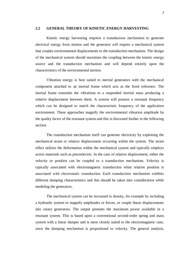
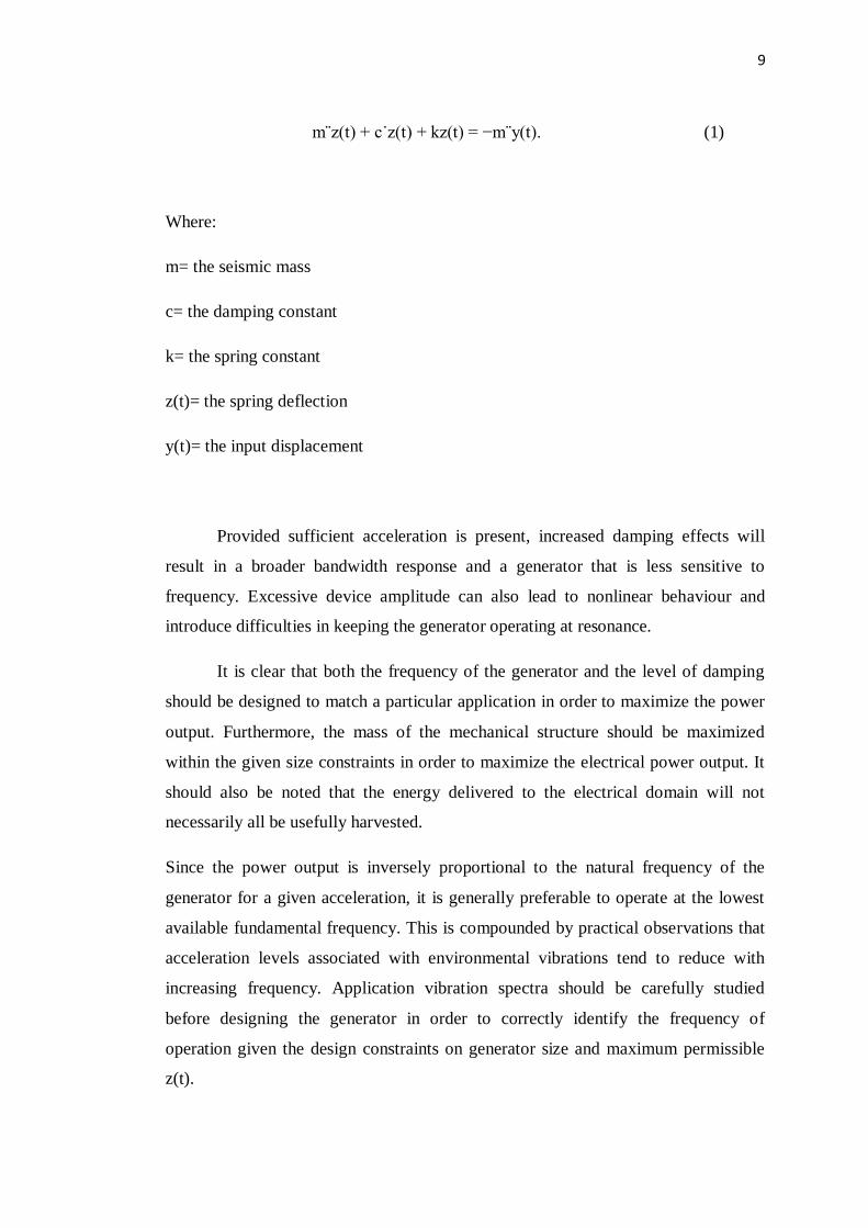
2.2 General Theory of Kinetic Energy Harvesting 7
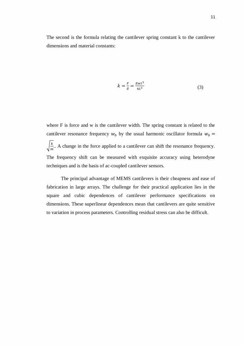
2.3 Effect of cantilever Beam in MEMS 11
2.4 The Magnetic Field and Faraday’s Law 13
2.5 Energy Harvesting From Vibration 15
2.6 Direct Force Applications Generator 16
2.7 Vibration Generator Effectiveness 17
ix
2.8 Common Vibration Sources 18
2.9 Type of Energy Harvester
2.9.1 Piezoelectric Generators
2.9.2 Electromagnetic Generators
2.9.3 Electrostatic Generators
Conclusion
19
19
21
23
27
CHAPTER 3 METHODOLOGY
3.0 Introduction 28
3.0 Flow Chart 29
3.1 Microgenerator Design And Dimensions 30
3.2 Experiment Materials 34
3.3 Tools And Software Used 38
3.4 Experimental Setup 42
3.5 Experiment Procedure 45
Conclusion 46
CHAPTER 4 RESULTS AND DISCUSSION
4.1 Introduction 47
4.2 Descriptive Analysis 48
4.3 Analytical/Theoretical Solution
4.3.1 Beam Stiffness
4.3.2 Natural Frequencies
50
50
51
4.4 Experiment Result
4.4.1 Signal Analysis
4.4.2 The Effect of Cantilever Beam Length Result
53
53
57
4.5 Problem Encountered 63
x
CHAPTER 5 CONCLUSION AND RECOMMENDATIONS
5.1 Introduction 64
5.2 Conclusion 65
5.3 Recommendation 66
REFERENCES
APPENDICES
A Gantt chart for Final Year Project 1 67
B Gantt chart for Final Year Project 2 68
xi
LIST OF TABLES
Table No. Title Page
2.8 Vibration sources 18
3.2 Physical and thermal properties of the magnet 39
3.2(a) Properties of materials 41
4.4.2(a) Max voltage produce from different cantilever beam length 62
4.4.2(b) Voltage output produced from 9 cm cantilever beam 63
4.4.2(c) Voltage output produced from 11 cm cantilever beam 64
4.4.2(d) Voltage output produced from 13 cm cantilever beam 65
4.4.2(e) Average voltage output produced from three different
cantilever beams
66
4.4.2(f) Voltage output produced from three different cantilever
beams
67
xii
LIST OF FIGURES
Figure No. Title Page
2.2 Inertial Generator 9
2.4 A magnetic field 14
2.9.1 Piezoelectric generator 18
2.9.2 Electromagnetic Transduction Principle Operation 20
2.9.3 Potential Motion Directions 22
2.9.3(a) Attractive Force Generated by Electric Field 24
2.9.3(b) Single Axis Isolation through Symmetry 25
2.9.3(c) Electrostatic Transducer Constant Charge Operating Principle 25
2.9.3(d) Planar Electrostatic Transduction 26
2.9.3(e) Rotary Electrostatic Transduction 27
3.0 Project flow 27
3.1 Cross section through the magnet arrangement 31
1 Side view of Design A 33
2 Full view of Design A 33
3 Design A 34
xiii
3.2 Neodymium Iron Boron (NdFeB) 37
3.2(a) Tinned Copper wire 38
3.2(b) Aluminum cantilever beams 38
3.3 PicoScope HP-3060 40
3.3(a) Data acquisition system (DAQ) 41
3.3(b) Shaker (Bruel and Kjaer, type 4826, Germany) 41
3.3(c) Power amplifier 42
3.3(d) Test rig to hang model 42
3.4 Experiment Configuration flow 43
3.4(a) Experiment setup 43
3.4(b) Model placement setup 44
3.4(c) Shaker placement at the center of the model 44
4.2(a) Experiment setup 49
4.2(b) Experiment setup up close 50
4.2(c) Overall experiment setup 50
4.41(a) 9 cm cantilever beam signal waves 54
xiv
4.4.1(b) 11 cm cantilever beam signal waves 55
4.4.1(c) 13 cm cantilever beam signal waves 55
4.4.1(d) 9 cm cantilever beam mean signal waves 56
4.4.1(e) 11 cm cantilever beam mean signal waves 56
4.4.1(f) 13 cm cantilever beam mean signal waves 57
4.4.2(a) Graph voltage versus cantilever beam length 58
4.4.2(b) Graph voltage versus frequency for 9 cm cantilever beam 59
4.4.2(c) Graph voltage versus frequency for 11 cm cantilever beam 60
4.4.2(d) Graph voltage versus frequency for 13 cm cantilever beam 61
4.4.2(e) Graph average voltage versus frequency for three different
cantilever beams
62
4.4.2(f) Graph voltage versus frequency for three different cantilever
beams
63
xv
LIST OF SYMBOL
m The Seismic Mass
c The Damping Constant
k The Spring Constant
z(t) The Spring Deflection
y(t) The Input Displacement
σ Stress
ν Poisson's Ratio
E Young's Modulus
δ Deflection
L The Beam Length
t Cantilever Thickness
Resonance Frequency
e Voltage Or Electromotive Force
Ø The Magnetic Flux
N Turn Of Coil
V Volt
Hz Hertz
I Inductance
R Resistance
Frequency
xvi
LIST OF ABBREVIATIONS
FEA Finite Element Analysis
PC Personal Computer
LED Light Emission Diode
LCD Liquid Crystal Display
MEMS Micro-Electromechanical Systems
NdFeB Neodymium Iron Boron
SIMO Signal Multi-Output
SISO Signal Single-Output
Viso Voltage Of Sinusoidal Signal
DAQ Data Acquisition System
1
CHAPTER 1
INTRODUCTION
1.1 INTRODUCTION
Electromagnetic induction was discovered by Faraday in 1831. The electric
current in a conductor located within a magnetic field. The conductor made from a
coil and the electricity is generated either the relative movement of the magnet and
coil or because of the changes in the magnetic field. The amount of electricity
generated depends on the strength of the magnetic field, the velocity of the relative
motion and the number of turns of the coil.
Developement in micro electromechanical systems (MEMS) has the point
where its applications to a wide range of areas are now very important for the future.
MEMS applications such as medical implants and sensors in buildings. The supply of
power to such systems has so far been through by a batteries. In long lived systems
where battery replacement is difficult and generating power from ambient sources
will becomes imperative. Systems that depend on batteries have a limited operating
life while systems having their own self-powered supply unit have a potentially
much longer life. Electromechanical systems convert energy from existing energy
sources within their environment into electrical energy. An alternative solution to
batteries is miniature renewable power supply units.
2
1.2 PROJECT BACKGROUND
Our approach is to use mechanical vibration as the ambient energy source for
electrical power generator. In this project, a vibration based on magnet and coil
power generator is being study and fabricate. The size of the device is small,
mechanical resonances tend to increase in frequency and it is the challenge of
generating power from the conversion vibration enrgy must be high as possible. The
performance of the proposed energy harvester structure is verified through study,
theory and it is shown that the Micro-Electromechanical Systems (MEMS) structure
can be used as an energy-harvesting device for low frequency applications. In order
to have an idea about the effect of scaling down the dimensions on the performance
of the energy harvester, testing method is developed in the frame of this further
study. For this method, a cantilever beam length scaling factor is proposed and the
dimensions of the devices to be tested are arranged according to this factor. It should
be noted that the thickness of the cantilever and the coil wire diameter are kept
constant respectively but the length of each beam is difference in this study. In
principle, either the magnets or the coil can be chosen to be mounted on the beam
while the other remains fixed. It is generally preferable, the magnets that attached to
the beam can act as the inertial mass. This is one of the most effective methods for
energy harvesting to produce electromagnetic induction by means of permanent
magnets, a coil and a resonating cantilever beam.
3
1.3 PROBLEM STATEMENT
The effect of the cantilever length on the performance of the harvester is
investigated. We measured and calculated resonance frequency and maximum peak
induced voltage for the electromagnetic energy harvester that have 4.5 mm wide
cantilever and two cascaded magnets. Electromagnetic energy harvester will test for
a certain range vibration frequency which 100 Hz until 500 Hz for different
cantilever beam lengths. The most important parameters influencing the design of
such a system are its beam length and it conversion energy efficiency. Number of
length beam increase, excitation increase and output voltage increase. The size is
dependent on the energy requirement and must be as small as possible. So that it will
be compatible with the general design objectives of MEMS. This project also
investigates the optimal coil turns for an electromagnetic power harvester. Turn coils
giving an effect to the power generation. Theoretically, the power harvested
increases proportionally with the radius and turn of the coil wire. Power generated by
the system is proportional to the voltage induced. Number of turn of coil increase,
magnetic flux increase, induced voltage increase.
1.4 OBJECTIVES
This project objective consists of:
1. Design an electromechanical energy harvester based on beam structure.
2. Analysis the effect of various length of beams to the voltage produced by the
energy harvester
4
1.5 SCOPE RESEARCH
The scopes of the project are limited to:
1. The relationship between frequencies and the amount of electricity produced.
2. Design a small size of energy harvester.
3. Beams are limited 3 length.
4. Outputs are presented on LCD and computer based.
1.6 CHAPTER OUTLINE
This report project is organized into five chapters. Each chapter will explain
in detail to complete my project whether in experiment or theoretical. The first
chapter will discuss about the project background, problem statement, project
objective and the scope of the project.
Chapter 2 will reviews some theory about energy harvester in many aspects
and the previous study about electromagnetic energy harvester. Analysis the effects
of cantilever beam with various length and turn of coil an electromagnetic energy
harvester is also explained in this chapter.
Chapter 3 presented the research methodology, the model design, the
procedures to complete my project and application tool that have been used in this
project.
Chapter 4 views the result of the amount electricity will produced in
electromagnetic energy harvester and discussion of the overall result. Analysis about
the output power, output voltage, coherence graph and its relation with natural
frequencies is also discussed in this chapter.
In final chapter, the project report is summarized and some recommendation
works are given to improve the project for future planning.
5
CHAPTER 2
LITERATURE REVIEW
The purpose of this chapter is to provide a review of past research efforts
related to micro energy harvester. A review of other relevant research studies is also
provided. Literature has been studied on theory, vibration source, and type of energy
harvester. Little information can be found on integrated evaluation methods. The
review is organized according to this study to offer insight on how past research
efforts have laid the groundwork for subsequent studies and include the present
research effort. The review is study in detail so that the present research effort can be
properly tailored to add to the present body of literature so that it will follow the
scope and direction of the present research.
Energy harvesting approaches transform light, heat and kinetic energy
available in the sensor environment into electrical energy and can offer the potential
of renewable power sources which can be replace the battery. It devices scavenge
energy from the environment such as ambient forced excitation, flow induced
vibration, wind power and electromagnetic energy harvester is the oldest techniques
for energy harvesting. There are few methods and studies have been conducted to
increase the performance and the amount of electricity to make sure utilization can
be improved. The subject in this paper refer to the kinetic energy generator which
converts mechanical energy in the form of vibrations into electrical energy. Kinetic
energy is typically converted into electrical energy using electromagnetic,
piezoelectric or electrostatic transduction mechanisms.
6
2.1 INTRODUCTION
The ambient vibrations has long been known and the energy produce from
ambient vibrations was too small for almost all applications for four decades ago.
The advancement of technology, increasing needs for energy and limitations of other
energy sources have been changing the feasibility calculations. There has been a
significant effort in the research community, government agencies and private
companies to generate electricity from the oscillations.
Advances in technology led to the development of electronic circuits and
sensors with extremely low electricity consumption. It is possible to operate these
devices accurately by using the energy harvested from ambient vibrations. These
advances in technology also reduced the cost of manufacturing for large structures.
Many technologies are available to make metals resistant to harsh operating
conditions and corrosion. There are many ways to convert mechanical energy into
electricity including hydraulic systems, piezoelectric materials and power generators.
The development of microelectromechanical systems (MEMS) has
highlighted a wide range of applications for miniature sensors and actuators. This has
made it possible to implant microsensors and actuators into a whole host of different
structures for applications such as medical implants, embedded sensors in buildings
and bridges. A promising alternative to batteries is miniature self-contained
renewable power supplies. Renewable power supplies convert energy from an
existing source within their environment into electrical energy. The sources of
energy available will depend on the application.
7
2.2 GENERAL THEORY OF KINETIC ENERGY HARVESTING
Kinetic energy harvesting requires a transduction mechanism to generate
electrical energy from motion and the generator will require a mechanical system
that couples environmental displacements to the transduction mechanism. The design
of the mechanical system should maximize the coupling between the kinetic energy
source and the transduction mechanism and will depend entirely upon the
characteristics of the environmental motion.
Vibration energy is best suited to inertial generators with the mechanical
component attached to an inertial frame which acts as the fixed reference. The
inertial frame transmits the vibrations to a suspended inertial mass producing a
relative displacement between them. A system will possess a resonant frequency
which can be designed to match the characteristic frequency of the application
environment. These approaches magnify the environmental vibration amplitude by
the quality factor of the resonant system and this is discussed further in the following
section.
The transduction mechanism itself can generate electricity by exploiting the
mechanical strain or relative displacement occurring within the system. The strain
effect utilizes the deformation within the mechanical system and typically employs
active materials such as piezoelectric. In the case of relative displacement, either the
velocity or position can be coupled to a transduction mechanism. Velocity is
typically associated with electromagnetic transduction whist relative position is
associated with electrostatic transduction. Each transduction mechanism exhibits
different damping characteristics and this should be taken into consideration while
modeling the generators.
The mechanical system can be increased in density, for example by including
a hydraulic system to magnify amplitudes or forces, or couple linear displacements
into rotary generators. The output presents the maximum power available in a
resonant system. This is based upon a conventional second-order spring and mass
system with a linear damper and is most closely suited to the electromagnetic case,
since the damping mechanism is proportional to velocity. The general analysis,
8
however, still provides a valuable insight into resonant generators and highlights
some important aspects that are applicable to all transduction mechanisms.
Figure 2.2 : Inertial Generator
Source: [C.B. Williams, 1995]
Inertial-based generators are essentially second-order, spring-mass systems.
Figure shows a general example of such a system based on a seismic mass, m, on a
spring of stiffness, k. Energy losses within the system are represented by the
damping coefficient, c. These components are located within the inertial frame which
is being excited by an external sinusoidal vibration of the form y(t) = Y sin(ωt).This
external vibration moves out of phase with the mass when the structure is vibrated at
resonance resulting in a net displacement, z(t), between the mass and the frame.
Assuming that the mass of the vibration source is significantly greater than that of
the seismic mass, not affected by its presence and also that the external excitation is
harmonic. The differential equation of motion is described as [C.B. Williams,
1995](1)
9
m¨z(t) + c˙z(t) + kz(t) = −m¨y(t). (1)
Where:
m= the seismic mass
c= the damping constant
k= the spring constant
z(t)= the spring deflection
y(t)= the input displacement
Provided sufficient acceleration is present, increased damping effects will
result in a broader bandwidth response and a generator that is less sensitive to
frequency. Excessive device amplitude can also lead to nonlinear behaviour and
introduce difficulties in keeping the generator operating at resonance.
It is clear that both the frequency of the generator and the level of damping
should be designed to match a particular application in order to maximize the power
output. Furthermore, the mass of the mechanical structure should be maximized
within the given size constraints in order to maximize the electrical power output. It
should also be noted that the energy delivered to the electrical domain will not
necessarily all be usefully harvested.
Since the power output is inversely proportional to the natural frequency of the
generator for a given acceleration, it is generally preferable to operate at the lowest
available fundamental frequency. This is compounded by practical observations that
acceleration levels associated with environmental vibrations tend to reduce with
increasing frequency. Application vibration spectra should be carefully studied
before designing the generator in order to correctly identify the frequency of
operation given the design constraints on generator size and maximum permissible
z(t).
10
2.3 EFFECT OF CANTILEVER BEAM IN MEMS
Cantilevered beams are the most ubiquitous structures in the field of
microelectromechanical systems (MEMS). MEMS cantilevers are commonly
fabricated from silicon (Si), silicon nitride (Si3N4), or polymers. The fabrication
process typically involves undercutting the cantilever structure to release it, often
with an anisotropic wet or dry etching technique. Without cantilever transducers,
atomic force microscopy would not be possible. A large number of research groups
are attempting to develop cantilever arrays as biosensors for medical diagnostic
applications. MEMS cantilevers are also finding application as radio frequency filters
and resonators. The MEMS cantilevers are commonly made as unimorphs or
bimorphs.
Two equations are key to understanding the behavior of MEMS cantilevers.
The first is Stoney's formula, which relates cantilever end deflection δ to applied
stress σ:
where ν is Poisson's ratio, E is Young's modulus, L is the beam length and t is the
cantilever thickness. Very sensitive optical and capacitive methods have been
developed to measure changes in the static deflection of cantilever beams used in dc-
coupled sensors.
(2)
11
The second is the formula relating the cantilever spring constant k to the cantilever
dimensions and material constants:
where F is force and w is the cantilever width. The spring constant is related to the
cantilever resonance frequency by the usual harmonic oscillator formula
√
.. A change in the force applied to a cantilever can shift the resonance frequency.
The frequency shift can be measured with exquisite accuracy using heterodyne
techniques and is the basis of ac-coupled cantilever sensors.
The principal advantage of MEMS cantilevers is their cheapness and ease of
fabrication in large arrays. The challenge for their practical application lies in the
square and cubic dependences of cantilever performance specifications on
dimensions. These superlinear dependences mean that cantilevers are quite sensitive
to variation in process parameters. Controlling residual stress can also be difficult.
(3)
12
2.4 THE MAGNETIC FIELD AND FARADAY’S LAW
Faraday law is a law that states an electric field is induced in any system in
which a magnetic field is changing with time [Giorgio Rizzoni, 2007]. The generated
voltage or induced electromotive force, emf (e) in any closed circuit is equal to the
time rate of change of the magnetic flux through the circuit. In the other word, the
emf generated is proportional to the rate of the magnetic flux. The induced voltage
represents
Where:
V @ e = voltage or electromotive force
Ø = the magnetic flux (Weber’s, Wb)
t = time (sec)
The coil is used to flow the current such a way that the magnetic flux
generated by the current would oppose the increasing flux. In practical applications,
the size of the voltages induced by the changing magnetic field can be significantly
increased if the conducting wire is coiled many times around. So as to multiply the
area crossed by the magnetic flux lines many time over. The induced voltage in the
coil could be approximated by the following expression:
Where:
N = turn of coil
(4)
(5)