Page 1
Horizon 2020 - LCE-2016-2017 - Competitive Low-Carbon Energy
FLEXCoop
Democratizing energy markets through the introduction of innovative
flexibility-based demand response tools and novel business and market models
for energy cooperatives
WP2 – Stakeholder Requirements, Business Models and
Architecture Design
D2.3 – Analysis of EU-wide Interoperability
Standards and Data Models and
Harmonization Requirements
Due date: 31.05.2018 Delivery Date: 14.06.2018
Author(s): Hrvoje Keko, Stjepan Sučić (Končar);
Konstantinos Tzanidakis, Christos Malavazos (Grindrop)
Peter Hasse, Armin Wolf (Fraunhofer)
Editor: Hrvoje Keko (Končar)
Lead Beneficiary of Deliverable: Končar
Dissemination level: Public Nature of the Deliverable: Report
Internal Reviewers: Karsten Isakovic (Fraunhofer), Peter Hasse (Fraunhofer),
Laura Morcillo Montalbá (ETRA), Germán Martinez (ETRA),
Jordi Cipriano (CIMNE)
Page 2
HORIZON 2020 – 773909 - FLEXCoop D2.3 – Analysis of EU-wide Interoperability Standards and
Data Models and Harmonization Requirements
WP2 – Stakeholders Req., Business Models, Architecture Design FLEXCoop Consortium Page 2 of 53
FLEXCOOP KEY FACTS
Topic: LCE-2016-2017 - Competitive Low-Carbon Energy
Type of Action: Research and Innovation Action
Project start: 01 October 2017
Duration: 36 months from 01.10.2017 to 30.09.2020 (Article 3 GA)
Project Coordinator: Fraunhofer
Consortium: 13 organizations from nine EU member states
FLEXCOOP CONSORTIUM PARTNERS
Fraunhofer Fraunhofer-Gesellschaft zur Förderung der angewandten Forschung e.V.
ETRa ETRA INVESTIGACION Y DESARROLLO SA
HYPERTECH HYPERTECH (CHAIPERTEK) ANONYMOS VIOMICHANIKI
DTU DANMARKS TEKNISKE UNIVERSITET
GRINDROP GRINDROP LIMITED
CIRCE FUNDACION CIRCE CENTRO DE INVESTIGACION DE RECURSOS
Y CONSUMOS ENERGETICOS
KONCAR KONCAR - INZENJERING ZA ENERGETIKUI TRANSPORT DD
SUITE5 SUITE5 DATA INTELLIGENCE SOLUTIONS Limited
CIMNE CENTRE INTERNACIONAL DE METODES NUMERICS EN
ENGINYERIA
RESCOOP.EU RESCOOP EU ASBL
SomEnergia SOM ENERGIA SCCL
ODE ORGANISATIE VOOR HERNIEUWBARE ENERGIE DECENTRAAL
Escozon ESCOZON COOPERATIE UA - affiliated or linked to ODE
MERIT MERIT CONSULTING HOUSE SPRL
Disclaimer: FLEXCOOP is a project co-funded by the European Commission under the
Horizon 2020 - LCE-2016-2017 - Competitive Low-Carbon Energy Programme under Grant
Agreement No. 773909.
The information and views set out in this publication are those of the author(s) and do not
necessarily reflect the official opinion of the European Communities. Neither the European
Union institutions and bodies nor any person acting on their behalf may be held responsible for
the use, which may be made of the information contained therein.
© Copyright in this document remains vested with the FLEXCOOP Partners
Page 3
HORIZON 2020 – 773909 - FLEXCoop D2.3 – Analysis of EU-wide Interoperability Standards and
Data Models and Harmonization Requirements
WP2 – Stakeholders Req., Business Models, Architecture Design FLEXCoop Consortium Page 3 of 53
EXECUTIVE SUMMARY
The compliance and use of open standards is a key success factor for the FLEXCoop project
and its further replication and commercialization. FLEXCoop Task 2.5 on “Smart Grids
Interoperability Standards Analysis and overall system architecture design” will provide the
required guidance and input to ensure the achievement of this key objective. It will review the
standardization landscape and evaluate the latest evolutions in DR, interoperability between
energy market stakeholders and communication between devices and systems. This initial
analysis, along with the results of FLEXCoop T2.1 on “Stakeholders Requirements, Business
Models and Architecture Design”, will result in the overall architecture of the FLEXCoop
framework and the specifications of the key components and their functionalities.
This deliverable examines the landscape of relevant standards, i.e. the current and expected
standardization environment, in the light of the timeline of FLEXCoop developments. This
environment is very broad and ranges from the market data exchange standards to in-home
communication with on-premises equipment. In order to simplify the navigation in the
standards environment, the deliverable divides the standards roughly in two groups: the
upstream standards relevant for the environment from FLEXCoop to the grid, market operator
and aggregators, and downstream standards, targeting communication and control of the
FLEXCoop-related in-house equipment. As the implementation details are still pending in the
parallel with T2.1, this document is not stating the architectural decisions taken for the
FLEXCoop framework. The final selection of standards to be supported will be finalized along
with the technical specification of the architecture. This document examines and documents the
standardization environment in which the FLEXCoop framework is expected to function.
Among general standards and upstream standards the key relevant ones are presented. Among
the downstream standards, the market situation is elaborated as support for the final selection
of protocols. The final selection of standards to be supported will be completed after a deeper
analysis of the FLEXCoop pilot sites. The upstream and downstream characteristics of a
particular standard only reflect the scope of application of these standards as for the FLEXCoop
to function, compliance with all of these standards is equally relevant as all of the steps from
upstream to downstream need to be functional.
Page 4
HORIZON 2020 – 773909 - FLEXCoop D2.3 – Analysis of EU-wide Interoperability Standards and
Data Models and Harmonization Requirements
WP2 – Stakeholders Req., Business Models, Architecture Design FLEXCoop Consortium Page 4 of 53
Table of Contents
FLEXCOOP KEY FACTS ................................................................................................................................... 2
FLEXCOOP CONSORTIUM PARTNERS ....................................................................................................... 2
EXECUTIVE SUMMARY ................................................................................................................................... 3
LIST OF FIGURES .............................................................................................................................................. 5
LIST OF TABLES ................................................................................................................................................ 5
ABBREVIATIONS ............................................................................................................................................... 6
1. INTRODUCTION ............................................................................................................................................. 8
2. DELIVERABLE CONCEPT AND OBJECTIVE(S) ..................................................................................... 9
3. STANDARDS OVERVIEW ........................................................................................................................... 11
3.1. IEC 62939 SMART GRID USER INTERFACE STANDARD .............................................................................. 12 3.1.1. DR implications of the IEC 62939 (include the similar structure in the next standards’ sections) ... 13
3.2. CIM – COMMON INFORMATION MODEL ..................................................................................................... 15 3.3. IEC 62746 SYSTEMS INTERFACE BETWEEN CUSTOMER ENERGY MANAGEMENT SYSTEM AND THE POWER
MANAGEMENT SYSTEM ..................................................................................................................................... 17 3.3.1. DR implications of the Open ADR standard ...................................................................................... 18
3.4. VHPREADY – VIRTUAL HEAT AND POWER READY .................................................................................... 20 3.5. USEF – UNIVERSAL SMART ENERGY FRAMEWORK ................................................................................... 21 3.6. UPSTREAM STANDARD: TOWARDS THE GRID AND WITHIN GRID OPERATION .............................................. 23
3.6.1. IEC 61850 Power Utility Automation Standard ................................................................................ 23 3.6.2. IEC 60870-5 series of standard protocols ......................................................................................... 27 3.6.3. Coverage of other upstream protocols .............................................................................................. 28
3.7. DOWNSTREAM STANDARDS: TOWARDS CUSTOMER FACILITIES MANAGEMENT AND CONTROL ................... 29 3.7.1. Introduction ....................................................................................................................................... 29 3.7.2. The FLEXCoop Approach ................................................................................................................. 29 3.7.3. Criteria for Evaluation for the FLEXCoop WSN Approach .............................................................. 31 3.7.4. Zigbee ................................................................................................................................................ 32 3.7.5. Bluetooth Low Energy (BLE)............................................................................................................. 34 3.7.6. Z-Wave ............................................................................................................................................... 37 3.7.7. EnOcean protocol .............................................................................................................................. 40 3.7.8. INSTEON ........................................................................................................................................... 42
3.8. DOWNSTREAM PROTOCOLS EVALUATION BASED ON THE FLEXCOOP-RELATED SELECTION CRITERIA ...... 45 3.9. MACHINE-TO-MACHINE ONTOLOGIES. HARMONISATION REQUIREMENTS. ................................................. 48
3.9.1. SAREF – Smart Appliance Reference Ontology ................................................................................ 48 3.9.2. oneM2M ............................................................................................................................................. 48
4. OVERVIEW OF EXAMINED STANDARDS ............................................................................................. 49
5. CONCLUSION................................................................................................................................................ 51
APPENDIX A: LITERATURE ......................................................................................................................... 52
Page 5
HORIZON 2020 – 773909 - FLEXCoop D2.3 – Analysis of EU-wide Interoperability Standards and
Data Models and Harmonization Requirements
WP2 – Stakeholders Req., Business Models, Architecture Design FLEXCoop Consortium Page 5 of 53
LIST OF FIGURES
Figure 1: FLEXCoop Coarse Architectural Overview (Draft version) ...................................... 9
Figure 2: IEC Smart Grid standards map (Source: IEC) .......................................................... 11
Figure 3: The Scope of IEC 62939 Standard: Conceptual Smart Grid model showing
communication requirements relevant for the IEC 62939 ............................................... 13
Figure 4: The envisioned scope of USEF................................................................................. 21
Figure 4: IEC 61850 edition 1.0 communication framework architecture .............................. 23
Figure 5: The coverage of IEC 61850 edition 2.0 series of standards ..................................... 24
Figure 6: Bird’s eye view of the IEC 61850 group of standard documents ............................. 25
Figure 7: Object hierarchy in the IEC 61850 data model ........................................................ 25
Figure 8: A map of IEC 61850 information model and ACSI services ................................... 26
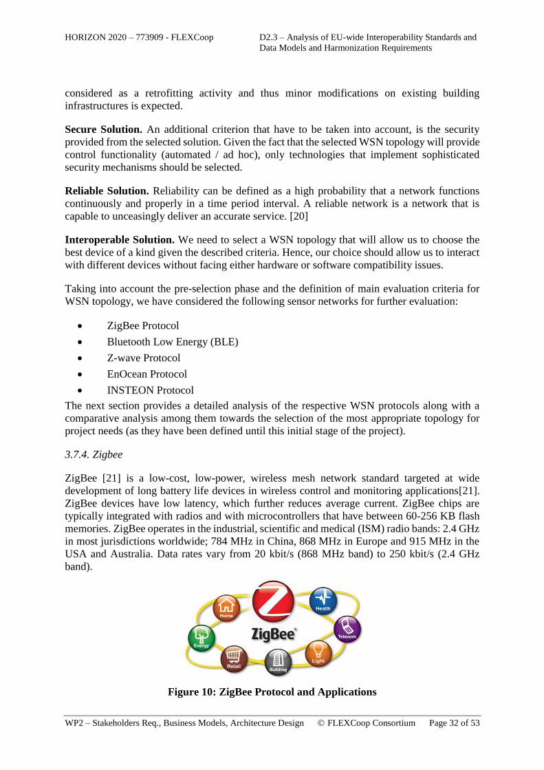
Figure 9: ZigBee Protocol and Applications ............................................................................ 32
Figure 10: ZigBee network topology ....................................................................................... 33
Figure 11: ZigBee network stack ............................................................................................. 33
Figure 12: The Bluetooth low energy software stack [24] ....................................................... 35
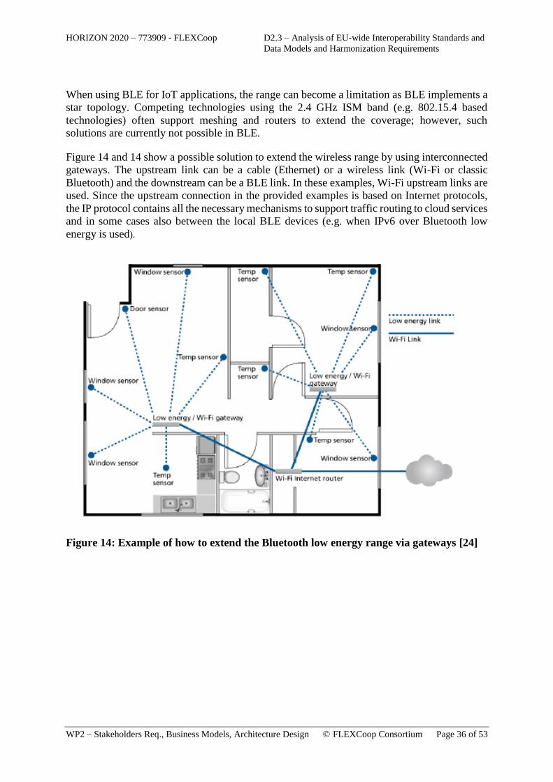
Figure 13: Example of how to extend the Bluetooth low energy range via gateways [24] ..... 36
Figure 14: Gateways as range extenders [24] .......................................................................... 37
Figure 15: Z-Wave mesh topology........................................................................................... 38
Figure 16: Z-Wave protocol stack ............................................................................................ 40
Figure 17: EnOcean Protocol Stack ......................................................................................... 41
Figure 18: INSTEON device communication [31] .................................................................. 43
Figure 19: INSTEON Message Repeating [31] ...................................................................... 44
Figure 20: Overview of FLEXCoop evaluation criteria for downstream protocols ................ 46
LIST OF TABLES
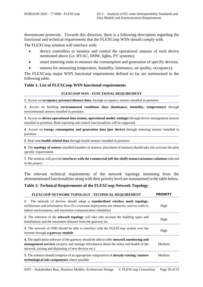
Table 1: List of FLEXCoop WSN functional requirements .................................................... 30
Table 2: Technical Requirements of the FLEXCoop Network Topology ............................... 30
Page 6
HORIZON 2020 – 773909 - FLEXCoop D2.3 – Analysis of EU-wide Interoperability Standards and
Data Models and Harmonization Requirements
WP2 – Stakeholders Req., Business Models, Architecture Design FLEXCoop Consortium Page 6 of 53
Table 3: Overview of examined standards: General and upstream-related standards ............. 49
Table 4: Overview of examined standards: Downstream-related standards ............................ 50
ABBREVIATIONS
BRP Balance Responsible Party
CIM Common Information Model
CO Confidential, only for members of the Consortium (including the Commission Services)
CSS Customer Support System
D Deliverable
DER Distributed Energy Resource
DMS Distribution Management System
DoW Description of Work
DR Demand Response
DSO Distribution System Operator
EAI Enterprise Application Integration
EMS Energy Management System
ENTSO-E European Network of Transmission System Operators for Electricity
ERP Enterprise Resource Planning
ESB Enterprise Service Bus
ETSI European Telecommunications Standards Institute
ESI Energy Services Interface
EV Electric Vehicle
FLOSS Free/Libre Open Source Software
GDEM Global Demand Manager for Aggregators
GIS Geographical Information System
GUI Graphical User Interface
H2020 Horizon 2020 Programme
ICT Information and Communication Technology
IEC International Electrotechnical Commission
IED Intelligent Electronic Device
IETF Internet Engineering Task Force
IoT Internet of Things
IPR Intellectual Property Rights
IT Information Technology
M2M Smart Machine-to-Machine
MGT Management
MS Milestone
Page 7
HORIZON 2020 – 773909 - FLEXCoop D2.3 – Analysis of EU-wide Interoperability Standards and
Data Models and Harmonization Requirements
WP2 – Stakeholders Req., Business Models, Architecture Design FLEXCoop Consortium Page 7 of 53
O Other
OS Open Source
OSB Open Smart Box
OWL Ontology Web Language (within the context of CIM OWL)
P Prototype
PAN Personal Area Network
P2H Power-to-Heat
PM Person Month
PU Public
PV Photovoltaic
R Report
RDF Resource Description Framework
RES Renewable Energy System
RTD Research and Development
SEAC Security Access Control
SGUI Smart Grid User Interface
SOA Service Oriented Architecture
UML Unified Modelling Language
USEF Universal Smart Energy Framework
VEN Virtual End Node
VTES Virtual Thermal Energy Storage
VTN Virtual Top Node
WS-Calendar Web Services Calendar
WP Work Package
WSN Wireless Sensor Network
XML eXtensible Markup Language
Y1 Year 1
Page 8
HORIZON 2020 – 773909 - FLEXCoop D2.3 – Analysis of EU-wide Interoperability Standards and
Data Models and Harmonization Requirements
WP2 – Stakeholders Req., Business Models, Architecture Design FLEXCoop Consortium Page 8 of 53
1. INTRODUCTION
The compliance and use of open standards is a key success factor for the project and its further
replication and commercialization. Task 2.5 will provide the required guidance and input to
ensure the achievement of this key objective. It will review the standardization landscape and
evaluate the latest evolutions in DR, interoperability between energy market stakeholders and
communication between devices and systems. Based on this initial analysis, along with the
results of Task 2.1, Task 2.5 will deliver the overall architecture of the FLEXCoop framework
and the specifications of the key components and their functionalities. Specifically, the
following aspects will be defined:
(i) Conceptual Architecture Design: an overview of the system architecture describing the
components and introducing the various sub-components, their interfaces and the connections
with external systems (i.e. interoperability with existing smart home systems, multi-sensorial
infrastructure or DERs at building and district level, interoperability interfaces for Machine to
Machine communication, interfaces for the communication between the different actors in the
DR value chain);
(ii) Modules’ Functional and Technical Specifications: the purpose of this part of the
architecture is twofold: i) to provide a high-level sketch of dependencies among different parts
of the framework (e.g. individual components interfaces, etc.) and ii) to describe in detail the
constraints of the system elements in terms of hardware and/or software resources,
compatibility with standards, etc.;
(iii) Detailed Design of Individual Components of the Framework: refers to the detailed
description of the functionalities, non-functional specifications as well as communicational
requirements for the high-level building blocks of the FLEXCoop framework. To deliver the
aforementioned architectural definitions and to materialise the conceptual architecture design,
state of the art software engineering tools will be used (e.g. UML activity and sequence
diagrams, actors, etc.)
Considering interoperability, scalability and flexibility of the FLEXCoop framework, the
Internet of Things paradigm will be followed while analysing and evaluating the suitability of
main standard-based communication protocols, smart home communication protocols (Zigbee,
Bluetooth, 6LowPan, Z-Wave), open standards and data models (OpenADR, oneM2M/
SAREF, USEF, IEC-61850) and data modelling approaches (JSON, XML)
In this document, the landscape of relevant standards is examined and the most relevant ones
are described and referenced. At this stage of the project, the complete implementation details
of the architecture have not yet been compiled, therefore this document is not an implicit
definition of architectural decisions to be taken. Instead, this document examines the
standardization environment in the light of FLEXCoop project developments and its expected
timeline.
Page 9
HORIZON 2020 – 773909 - FLEXCoop D2.3 – Analysis of EU-wide Interoperability Standards and
Data Models and Harmonization Requirements
WP2 – Stakeholders Req., Business Models, Architecture Design FLEXCoop Consortium Page 9 of 53
2. DELIVERABLE CONCEPT AND OBJECTIVE(S)
This deliverable covers the standardization landscape regarding the latest evolutions in demand
response, interoperability between market stakeholders, and communication between devices
and systems.
The first draft of the FLEXCoop coarse architecture scheme is summarized as follows:
Figure 1: FLEXCoop Coarse Architectural Overview (Draft version)
It is immediately notable, even from a high level overview, that there is a significant number of
standards that the FLEXCoop architecture has to keep in mind and build upon. The standards
certainly differ in scope and the stakes involved, however they cannot easily be divided in the
classes of importance and relevance for the FLEXCoop project. A number of standards
presented here may have only a relatively limited application scope, e.g. communication within
a particular home, but incompatibilities at that level can have an adverse effect on the system
functionality overall and conversely on the system viability. For the FLEXCoop system promise
to be delivered, all steps have to operate correctly, from the lowest level regarding the field area
equipment and smart devices, all the way up to the highest level where the global demand
manager communicates to the network and market operators. For this reason, this document
does not aim to rank the standards by their order of importance, but instead to deliver an
overview of the relevant standards for the operational practice of FLEXCoop.
Page 10
HORIZON 2020 – 773909 - FLEXCoop D2.3 – Analysis of EU-wide Interoperability Standards and
Data Models and Harmonization Requirements
WP2 – Stakeholders Req., Business Models, Architecture Design FLEXCoop Consortium Page 10 of 53
The FLEXCoop system belongs to a larger context of the smart grid, a highly integrated and
distributed system of interfaced subsystems covering generation, transmission, distribution,
distributed energy resources and resources on customer premises. Commonly, the underlying
information is standardized based on the Common Information Model (CIM) [1]. Along with
the CIM standard, probably the most important protocols appearing in the architecture at the
grid level are stemming from the IEC 61850 series of protocols [2]. The IEC 61850 started as
an international standard defining communication protocols for intelligent electronic devices at
electrical substations. It has been developed as part of the IEC TC 57’s reference architecture
for electric power systems, and at the moment goes beyond the scope of electrical substations,
and it is practically a specification for the automation architecture. In practice, there is a number
of other used communication standards, and among them, the IEC 60870-5-104 standard [3]
is the most prominent one. However, when compared to the IEC 61850, the scope of such
standards is much narrower and is restricted to communication protocols. One can state that
currently, in today’s electric power networks, the IEC 61850 standard covers the process, field
and station, and the CIM standards are relevant in the scope of business operations, enterprise
and market, with common coverage, as can be seen in subsequent sections of this document.
Nowadays, both CIM and IEC 61850 standards are applied in almost all domains of electrical
power engineering (generation, transmission and distribution), and will also be relevant for the
scope of the FLEXCoop project.
While the aforementioned standards are of crucial importance for the electric power network,
once inside the premises of the smart grid customer, there is a number of different information
models and communication protocols used for direct facilities and equipment management and
control (as an example, the carrier can be ZigBee or Bluetooth). Notably, the technologies used
with different purposes may be incompatible with each other, and many of the existing systems
involved utilize legacy and outdated protocols in which the end user has no motivation on
replacing due to capital costs and time involved.
As stated previously, many of the standards have their place in different layers of the proposed
system, and for the FLEXCoop promise of flexibility-based DR tools to function, all the
communication steps in the chain from the tools run by the aggregator down to the actual smart
devices responding to the demand flexibility requirements need to be functional.
Page 11
HORIZON 2020 – 773909 - FLEXCoop D2.3 – Analysis of EU-wide Interoperability Standards and
Data Models and Harmonization Requirements
WP2 – Stakeholders Req., Business Models, Architecture Design FLEXCoop Consortium Page 11 of 53
3. STANDARDS OVERVIEW
Figure 2: IEC Smart Grid standards map (Source: IEC)
The figure above illustrates the vast landscape of IEC standards related to smart grid. This
document focuses on those relevant ones for the FLEXCoop project. This document firstly
introduces the IEC 62939 standard: the Smart Grid User Interface standard [4]. In this standard
name, the user is not the end user, the person using the electrical equipment. Instead, this
standard defines how the components (i.e. the equipment) are interfacing with the smart grid
infrastructure. These components are users of the SG infrastructure, and as the FLEXCoop
system will be one of such users utilizing the smart grid, this standard is highly relevant for the
FLEXCoop project as well.
Afterwards, the CIM model is described, in particular its applications to electric network
modelling and the exchange of wholesale market data. Then the IEC 62746 series of standards
is introduced, and particularly the IEC 62746-10 as an IEC adaptation of the Open Automated
Demand Response standard (OpenADR). Along with OpenADR, two industry-driven
standardization efforts have been presented – the VHPready and USEF.
Subsequently, the document presents the relevant standards divided into two groups: upstream
and downstream standards. As aforementioned described in the introduction, this division only
serves for the ease of understanding on where a particular standard fits within FLEXCoop. The
upstream standards are relevant within the scope of the grid, thus “upstream” from the proposed
FLEXCoop architecture in terms of network level. The downstream standards are mostly the
ones confined to the end-user premises (e.g. within a building).
Page 12
HORIZON 2020 – 773909 - FLEXCoop D2.3 – Analysis of EU-wide Interoperability Standards and
Data Models and Harmonization Requirements
WP2 – Stakeholders Req., Business Models, Architecture Design FLEXCoop Consortium Page 12 of 53
The IEC 62939, CIM, IEC 62746 (OpenADR), VHPready and USEF have been excluded from
the upstream-downstream definition as they are, in a certain way, relevant for both scopes.
These standards may influence the FLEXCoop architecture overall, including the internal
communication of the FLEXCoop modules. The IEC 62939 standard defines the models of
interfacing towards the smart grid, the CIM standard is ubiquitous in the power sector. The
OpenADR, VHPready and USEF standards and relevant concepts influence the architectural
decisions within the proposed FLEXCoop architecture as well, not just at its boundaries.
However, this document does not aim to prejudice the definition of the FLEXCoop components
in any way, as these will be defined in the implementation phase. Specifically, the deliverable
that will determine the implementation details is the WP2 deliverable D2.6 - FLEXCoop
Framework Architecture including functional, technical and communication specifications, due
4 months after this deliverable. Instead, only the general landscape of relevant standards that
FLEXCoop needs to adapt to is defined in this document, highlighting the most important and
generally relevant characteristics of each standard.
3.1. IEC 62939 Smart Grid User Interface standard
This standard aims to define the Smart Grid User Interface (SGUI) reference architecture, on
how to build interfaces for information exchange between the CIM model and diverse customer
facility standards. Several ecosystems (energy, telecommunication, home automation) have
been growing in coexistence separately sharing the location at the customer premise. Smart
homes and smart buildings, distributed energy resources, and electric vehicles point into the
direction to empower consumers, not only passively consuming energy from the grid, but also
feeding power back (a.k.a. “prosumer”). This poses a number of technical and organizational
challenges for the grid management.
In line with this perspective, a new standard has been deemed necessary, in order to ensure
effective, economical and secure operation of the power grid, as well as to increase efficiency
of demand-side systems and equipment, while at the same time keeping open the paths for new
business models. This is particularly relevant to information exchange between different actors,
as it now begins to play an increasingly important role. The IEC 62939 standard is directed
towards standardization of the interfacing methods and solutions that exchange information
with the smart grid, and is closely tied to the OASIS Energy Interoperation [5]. The FLEXCoop
strategy is certainly within in alignment with the objectives and requirements of IEC 62939.
The IEC 62939 specifies services for symmetric interoperation between energy suppliers and
energy consumers across the SGUI, connecting customer systems to the power system. The
services enable the coordination of operative systems that supply or consume energy over time
across the SGUI, including:
- an information model and a communication model,
- services for demand response, including dispatch of load resources and price,
- services for measurement and confirmation of response and delivery,
- services to enable collaborative and transactive use of energy across the SGUI
- service definitions consistent with the concept of a Service-Oriented Architecture,
- XML vocabularies for the interoperable and standard exchange of Transactive Energy
and
- XML vocabularies for the interoperable and standard exchange of Demand Response,
including the exchange of measurement and confirmation of response and delivery.
Page 13
HORIZON 2020 – 773909 - FLEXCoop D2.3 – Analysis of EU-wide Interoperability Standards and
Data Models and Harmonization Requirements
WP2 – Stakeholders Req., Business Models, Architecture Design FLEXCoop Consortium Page 13 of 53
Figure 3: The Scope of IEC 62939 Standard: Conceptual Smart Grid model showing
communication requirements relevant for the IEC 62939
In IEC 62939, the Energy Interoperation Services describes an information and communication
model to coordinate energy supply, transmission, distribution, and use, including power and
ancillary services, between any two parties, such as energy suppliers and customers, markets
and service providers, in any of the domains indicated in Figure 3 above. The Energy
Interoperation Services, as posted by the IEC 62939 standard, makes no assumptions about
which entities will enter those markets, or as to what those market roles will be called in the
future, and is not limited solely to the interfaces indicated in the figure, i.e. there may be new
actors and new scopes of communication appearing and the 62939 architecture is expected to
be applicable there as well.
3.1.1. DR implications of the IEC 62939 (include the similar structure in the next standards’
sections)
The IEC 62939 defines an Energy Services Interface (ESI). This is an abstraction of the SGUI
for both energy consumers and producers. The ESI is the surface where Energy Interoperation
Services are exchanged. The ESI is the external face of the energy-consuming or supplying
node. The ESI may be directly on an energy management system in the end node, or it may be
mediated by other business systems. The ESI is the point of communication whereby the entities
(e.g. utilities, ISOs) that produce and distribute electricity interact with the entities (e.g.
facilities and aggregators) that manage the consumption of electricity. An ESI may be in front
of one system or several, one building or several, or even in front of a microgrid.
In terms of IEC 62939, a Resource (as used in Energy Interoperation) is any logical entity that
is dispatchable. The Resource is solely responsible for its own response. A resource description
specifies the performance envelope for a Resource. If a Resource can participate in multiple
markets, it may have multiple descriptions (referring to the same technical unit, i.e. the
Page 14
HORIZON 2020 – 773909 - FLEXCoop D2.3 – Analysis of EU-wide Interoperability Standards and
Data Models and Harmonization Requirements
WP2 – Stakeholders Req., Business Models, Architecture Design FLEXCoop Consortium Page 14 of 53
Resource here does not have a 1:1 mapping to the physical world). A Resource is something
that can describe its capabilities in a Tender into a market. A Sequence is a set of temporally
related intervals with sharing information that changes over time.
A tender is an offering for a Transaction: a binding commitment between parties entered into
under an agreement. The Transactive Energy describes the established process of parties buying
and selling energy based on tenders (buy or sell offers) that may lead to transactions among
parties. In open wholesale forward energy markets, a generator may tender a quantity of energy
at a price over a future delivery interval of time to a customer. Acceptance of a tender results
in a binding transaction. In some cases, the transaction requires physical delivery of energy. In
other cases, the transaction is settled for cash at a price determined by a prescribed price index.
The use of Energy Interoperation Services enables present and future wholesale and retail
energy markets and retail tariffs, including dynamic and multi-part tariffs.
This standard is particularly interesting in utilizing the Virtual End Node (VEN) and Virtual
Top Node (VTN) concepts, similarly to OpenADR. The VEN has operational control of a set
of resources and/or processes and is able to control the output or demand of these resources to
affect their generation or utilization of electrical energy intelligently in response to an
understood set of smart grid messages. The VEN may be either a producer or consumer of
energy. The VEN is able to communicate (2-way) with a VTN receiving and transmitting smart
grid messages that relay grid situations, conditions, or events. A VEN may take the role of a
VTN in other interactions. VTNs and VENs may be structured in a tree-like hierarchy; however
any communication between nodes at the same hierarchy levels is not supported.
Within the framework of IEC 62939, the VTN is a party which role is the aggregation of
information and capabilities of distributed energy resources. The VTN is able to communicate
with both the Grid and the VEN devices or systems in its domain. A VTN may take the role of
a VEN interacting with another VTN.
Furthermore, the OASIS WS-Calendar (Web Services Calendar) specification is used as a
standardized form to communicate schedules and intervals. WS-Calendar extends the Internet
Engineering Task Force (IETF) iCalendar, a recognized basis standard for all personal
scheduling, to support machine-based negotiation of human-centric schedules. WS-Calendar
schedules energy production and its usage, as well as Demand Response and transactions
involving specific delivery schedules. The WS-Calendar is a de-facto standard for all schedule
transactions in the domain of smart grids.
Based on the above concepts, the IEC 62939 standard defines a service-oriented approach to
energy interactions. The standard focuses on the desired results, instead of the requested
processes and proposes a loose integration of the services provided. As the architectural
decisions and locational specifics of the FLEXCoop pilot sites would directly define which
parts of IEC 62939 will be implemented, for more details on the IEC 62939 standard a reader
is advised to consult the standard directly [4].
Page 15
HORIZON 2020 – 773909 - FLEXCoop D2.3 – Analysis of EU-wide Interoperability Standards and
Data Models and Harmonization Requirements
WP2 – Stakeholders Req., Business Models, Architecture Design FLEXCoop Consortium Page 15 of 53
3.2. CIM – Common Information Model
The Common Information Model (CIM) is an open standard that defines how managed
elements in an IT environment are represented as a common set of objects and relationships
between them. The CIM model, in the context of electric power engineering, is an ontology
model allowing the exchange of information of the electric grid among different software
applications. CIM model was developed by the electric power industry, and afterward officially
adopted by the International Electrotechnical Commission (IEC), as the IEC 61968/61970
series of standards [1]. The initial development of CIM was planned with the objective of
developing a common power system network model, to have a common basis to exchange
information.
The CIM standard has been adopted by the main part of vendors, in order to allow the exchange
of information among different devices, and it has been extended to cover tasks related to
electric power industry, such customer billing, work scheduling and asset tracking.
The core of the CIM model is mainly composed by the series of standards IEC 61970 and IEC
61968.
The principal objective of the IEC 61970 series of standards is to produce standards which
facilitate the integration of energy management systems (EMS) applications developed
independently by different vendors, between entire EMS systems developed independently, or
between an EMS system and other systems concerned with different aspects of power system
operations, such as generation or distribution management systems (DMS). In particular, the
IEC 61970-301 [6] standard describes the components of a power system at an electrical level
and relationships among them. The IEC 61968-11 [7] standard defines semantics of other
aspects of power system software data exchange such as work scheduling or customer billing.
In fact, the IEC 61968-11 standard defines information exchange between electrical distribution
systems on a utility enterprise level, in particular for the DMS functionalities. As the DMS is
designed to monitor and control the entire distribution network, this means that the standard
provides support for utilities such as outage management, by linking together the SCADA
system with e.g. geographic information systems, customer information and support systems
etc. This provides support for utilizing the joint benefits of having all the relevant information
from these systems available and combined. Generally, the IEC 61968-11 is supposed to be
implemented with middleware services brokering messages among applications, which means
than it can also be applied in the FLEXCoop architecture/project.
Because the CIM model is an ontology model, it must deal with exchanges of information with
all types of systems such as GIS (Geographical Information Systems), CSS (Customer Support
System) or ERP (Enterprise-Resource Planning). With this purpose CIM covers 53 UML
packages (Unified Modelling Language), containing approximately 820 classes with more than
8500 attributes. In addition, different serializations exist, such as XML and XML schema for
building its own EAI (Enterprise Application Integration) messages based on the CIM and to
use pre-defined messages built by IEC. In the case of modelling graphs of power grids, the CIM
model is provided with RDF (Resource Description Framework) serializations and RDF
schemas, as well as by CIM OWL (Ontology Web Language) serializations.
Page 16
HORIZON 2020 – 773909 - FLEXCoop D2.3 – Analysis of EU-wide Interoperability Standards and
Data Models and Harmonization Requirements
WP2 – Stakeholders Req., Business Models, Architecture Design FLEXCoop Consortium Page 16 of 53
The extensive applicability of the CIM model makes it one of the biggest standardized domain
ontologies, especially in conjunction with the IEC 61850 series of standards. Currently efforts
to harmonize the two main ontologies have been applied in the field of Smart Grids.
The CIM model is in wide adoption and it has been used by the ENTSO-E, European Network
of Transmission System Operators for Electricity. It is an organization of 43 electricity
transmission system operators in 36 countries across Europe, thus extending beyond the EU.
The initial mission of CIM is currently widely applied across Europe through the use of
CGMES: Common Information Model for Grid Models Exchange standard [8], however the
CIM is embedded into numerous processes of transmission and distribution system operators
across Europe, which makes the CIM relevant for all levels of the FLEXCoop project.
Furthermore, almost all market operators in Europe use CIM-derived XML-based protocols for
communications related to energy markets, which is being established as the IEC 62325 series
of standards [9]. The IEC 62325 series of standards are very wide in scope and consist in the
following parts (detailed in separate IEC 62325 standard documents):
- IEC 62325-301: Common information model (CIM) extensions for markets
- IEC 62325-351: CIM European market model exchange profile
- IEC 62325-450: Profile and context modelling rules
- IEC 62325-451-1: Acknowledgement business process and contextual model for CIM
European market
- IEC 62325-451-2: Scheduling business process and contextual model for CIM
European market
- IEC 62325-451-3: Transmission capacity allocation business process and contextual
models for European market
- IEC 62325-451-4: Settlement and reconciliation business process, contextual and
assembly models for European market
- IEC 62325-451-5: Problem statement and status request business processes, contextual
and assembly models for European market
- IEC 62325-451-6: Publication of information on market, contextual and assembly
models for European style market
- IEC 62325-452: North American style market profiles
- IEC 62325-502: Profile of ebXML (and its conversion)
- IEC 62325-503: Market data exchanges guidelines for the IEC 62325-351 profile
- IEC 62325-504: Utilization of web services for electronic data interchanges on the
European energy market for electricity
- IEC 62325-550-2: Common dynamic data structures for North American style markets
- IEC 62325-552-1: Dynamic data structures for day ahead markets (DAM)
Without any doubt, the CIM and the relevant CIM-derived XML market data exchange
protocols are crucial for the FLEXCoop framework to ensure compatibility with the energy
market stakeholders.
Page 17
HORIZON 2020 – 773909 - FLEXCoop D2.3 – Analysis of EU-wide Interoperability Standards and
Data Models and Harmonization Requirements
WP2 – Stakeholders Req., Business Models, Architecture Design FLEXCoop Consortium Page 17 of 53
3.3. IEC 62746 Systems interface between customer energy management system and the
power management system
The IEC 62746 standard is fully named “Systems interface between customer energy
management system and the power management system”. This standard defines the system
interfaces and communication protocols covering the whole chain between a smart grid and
smart home/building/industrial area. Therefore, the IEC 62746 standard is of highest relevance
for the FLEXCoop project.
The IEC 62746 standard provides application-level service communication that can be used to
incentivize responses from the customer-owned and customer-located distributed energy
resources. Price and demand response signals enable provision of indirect control of customer-
owned devices. The IEC 62746 standard does not specify the transport mechanisms. The
transport mechanisms and their interaction patterns are defined, as well as cyber security
mechanisms necessary to provide non-repudiation and mitigation of cyber-security risks, but
the actual “on the wire” transport mechanism is out of scope of this standard. IEC 62746
standard is agnostic in relation to the DR load control strategies, as well as to the market-
specific contractual or business agreements – these are also out of scope of the definition of this
standard.
In IEC 62746, the following services are specified:
- Register: identification of entities in advance of interactions with other parties
- Event: core demand response event, providing event functions and information models
for price-responsive DR
- Report: this service enables feedback to provide either periodic or one-time information
on the actual state of a resource and
- Opt: addressing the short-term changes in availability, providing the facility to
communicate opt-in and opt-out schedules from virtual end nodes to virtual top nodes.
For the FLEXCoop project, the most relevant standard among the 62746 group of standards is
probably the IEC 62746-10 [10]: Open Automated Demand Response (OpenADR 2.0b Profile
Specification), which represents the adoption of the OpenADR Alliance standard as the IEC
standard. This standard is a flexible data model to facilitate common information exchange
between electricity service providers, aggregators, and end users. The concept of an open
specification is intended to allow anyone to implement the two-way signalling systems,
providing the servers that publish information to the automated clients subscribing to the
information. This standard covers the signalling data models and includes information related
to specific DR electric reduction or shifting strategies, which are taken at the facility. This
standard can be leveraged to manage customer energy resources, including load, generation and
storage, via signals provided by grid and/or market operators. These resources may be identified
and managed as individual resources with specific capabilities, or as virtual resources with an
aggregated set of capabilities.
The OpenADR specifications provide:
- A minimal data model and services for DR, pricing, and distributed energy resource
(DER) communications.
Page 18
HORIZON 2020 – 773909 - FLEXCoop D2.3 – Analysis of EU-wide Interoperability Standards and
Data Models and Harmonization Requirements
WP2 – Stakeholders Req., Business Models, Architecture Design FLEXCoop Consortium Page 18 of 53
- How to implement a two-way signalling system to facilitate information exchange
between electricity service providers, aggregators and end users.
- A description of demand response signalling in terms of servers (virtual top nodes) that
are publishing information to automated clients (virtual end nodes) being the subscribers
of the information.
3.3.1. DR implications of the Open ADR standard
The OpenADR standard started as an open-source smart grid communications standard used
for demand response applications. Typically, it is used in explicit demand response scenarios
when specific signals are sent to cause devices to be turned off during periods of higher demand.
For explicit DR the automation of decisions is crucial: a standard that facilitates quick, fail-
safe, consistent and secure bi-directional communication between a large variety of
stakeholders is an absolute necessity.
The main features of OpenADR communication profiles (and by extension of the IEC 62746-
10 compliant profiles) are as follows:
- Continuous, secure, and reliable two-way communications infrastructures where the end
points at the end-use site receive and acknowledge the receipt of DR signals from the
energy service providers.
- Translation of DR event information to continuous Internet signals.
- Automation through the use of pre-programmed demand response strategies determined
and controlled by the end-use participant (without a need for interaction for each of the
transactions).
- Opt-Out enabled: override function to any participants for any DR event if the event
comes at a time when changes in end-use services are not desirable.
OpenADR uses a Service-Oriented Architecture (SOA) in which all interactions occur between
entities called Virtual Top Nodes (VTNs) and Virtual End Nodes (VENs).
There are two OpenADR profiles: Profile A, targeted towards low end devices and limited to a
simple implementation of OpenADR: while Profile B is targeted toward fully functional control
systems and devices and enable feedback and additional services. An additional profile is
currently being developed to implement an even more complete version of OpenADR and is
specifically aimed at aggregators.
The adoption of OpenADR 2.0b profile is by the IEC as the IEC 62746-10 is ongoing, withinthe
wider IEC 62746 standard series. This series describes a set of use cases related to energy
flexibility and demand side management, as well as an outline of potential upcoming Smart
Building and Smart Home scenarios. Thus the FLEXCoop developments may influence the
final IEC standard series. The IEC 62746 series provides a technical specification and
architecture for the management of customer and distributed energy resources that leverages
other existing IEC standards and links the standard to those. Of these, the most relevant is the
IEC 61850 standard (as indicated by the mention of VTN and VENs).
The OpenADR 2.0b profile supports the following:
- EiEvent – to notify the VENs of upcoming DR events and sending DR signals from
VTN to VEN
Page 19
HORIZON 2020 – 773909 - FLEXCoop D2.3 – Analysis of EU-wide Interoperability Standards and
Data Models and Harmonization Requirements
WP2 – Stakeholders Req., Business Models, Architecture Design FLEXCoop Consortium Page 19 of 53
- EiOpt – opt-in and opt-out capability by the VEN
- EiReport – specifies the report by the VEN to the VTN; typically supports the VTN’s
prediction and monitoring capabilities
- EiRegisterParty – establishment of communication between a VEN and a VTN.
In the OpenADR 2.0a profile, only a simplified EiEvent is possible.
The implementation of the services relies on standard-based IP communications such as HTTP
and XML Messaging and Presence Protocol (XMPP). The demand-response signals make the
VTN interact with a VEN in order to influence or change the load profiles of the demand-side
loads, associated with the VEN in question. Two types of signals can be used: prices and load
dispatches. The prices might be used if the objective is to incentivize the demand-side resource
to change the load profile with a price incentive, thus implicitly. In a load dispatch signal there
is an explicit instruction on what the load profile should be.
The specification of the OpenADR supports a wide range of different types of signals including
direct load control interactions. The OpenADR standard only provides the DR message
exchange and none of the actual underlying application logic. In other words, for the automated
DR to function, VENs have to implement the actual application logic.
As a conclusion of the IEC 62746 standard, it states a set of mandatory and optional attributes
within each of the services to meet broader interoperability, testing and certification. The
FLEXCoop solution will have to be, in one form or another, compliant with the IEC 62746
standard. In fact, the developments of FLEXCoop may even influence the parts of the standard
that are currently in the acceptance process.
Page 20
HORIZON 2020 – 773909 - FLEXCoop D2.3 – Analysis of EU-wide Interoperability Standards and
Data Models and Harmonization Requirements
WP2 – Stakeholders Req., Business Models, Architecture Design FLEXCoop Consortium Page 20 of 53
3.4. VHPready – Virtual Heat and Power Ready
VHPready – Virtual Heat and Power Ready [11] is an open specification for networking and
control decentralized power plants, originally developed and published by Vattenfall.
Vattenfall’s latest version 3.0 is freely accessible. In the current version 4.0, the VHPready
standard supports the connection of combined heat and power plants, battery storage, heat
pumps and wind turbines. The communication-technological basis is made up of Internet
protocols as well as the IEC 60870-5-104 (signal-oriented) or IEC 61850-7-420 (object-
oriented).
An essential feature of VHPready is the support of the transmission of timetables or of timetable
changes as well as the implementation and monitoring of the timetable operation of power
plants. Timetables or timetable changes can be specified to the minute and consist of service
blocks defined by start time, duration and a percentage value according to a default power value.
VHPready basically offers the possibility of flexibilities – e.g. for the provision of balancing
power, while otherwise ensuring that these timetables are feasible, i.e. represent a permissible
flexibility option. With the establishment of the industrial forum VHPready e.V. in February
2014 fifteen well-known companies laid out the foundation for cross-industry and multi-vendor
development of virtual power plants. In the industrial forum VHPready e.V. they work together
with others (currently approx. 50 member companies) continuously on a specification for a
standardized integration of decentralized energy systems.
The VHPready standard defines the communication path between a control center and a
distributed energy resource. The standard includes coverage on the security and the
interoperability of the connection. Regarding communications and security VHPready is based
on secured internet protocol technologies with TLS 1.2 encryption and the well-established IEC
protocols 60870 and 61850. VHPready is defining operating conditions, systems behavior and
performance as well as interfaces and data points in an exact and explicit way. By doing so,
distributed energy systems can be integrated into a VHPready network without any additional
engineering effort. Security in data communications as well as in systems operation is a
significant part of the currently developed standard. VHPready is providing the basis for
existing and future market models in the energy sector and contributes to a stable and reliable
energy supply in Germany, Europe and worldwide. Recently, a position statement on the
relation of VHPReady and OpenADR has been published on the VHPReady web site [11],
indicating there have been talks between the VHPReady industry alliance and the OpenADR
alliance about cooperation and mutual support for open, industry driven standard for the smart
grid. This is exactly the environment where FLEXCoop developments will operate, thus these
two protocols along with USEF have been singled out in this document, as these standards may
influence the FLEXCoop architectural decisions overall.
Page 21
HORIZON 2020 – 773909 - FLEXCoop D2.3 – Analysis of EU-wide Interoperability Standards and
Data Models and Harmonization Requirements
WP2 – Stakeholders Req., Business Models, Architecture Design FLEXCoop Consortium Page 21 of 53
3.5. USEF – Universal Smart Energy Framework
The USEF – Universal Smart Energy Framework [12] is an international standard, with an aim
to ensure smart energy technologies and projects are interconnectable and at lowest cost. USEF
is an industry initiative, driven by USEF Foundation, a non-profit industry alliance of seven
organisations and companies, active in the smart energy industry (ABB, Alliander, DNV GL,
Essent, IBM, ICT Automation and Stedin).
Figure 4: The envisioned scope of USEF
The USEF has a quite large envisioned coverage (Figure 5): it includes market-based control
mechanisms and the underlying ICT architecture, with the interfaces towards the actual
downstream devices (products) and upstream services and propositions. The USEF describes
the market for flexibility, offering the Framework description, with specifications, designs and
implementation guidelines. There is a reference implementation of USEF and the knowledge
from USEF pilots is available from the USEF foundation, we support users with insights,
structure and sample coding. The reference implementation is a fully functional implementation
of the USEF specification that has passed conformance testing, it is publicly available in the
form of downloadable source code under Apache 2.0 license, and it is a definitive interpretation
of the specification [13]. It is not, however, an operational platform nor is it tailored for specific
needs of a pilot project.
The idea of USEF is to enable the commoditisation and market trading of flexible energy use
and specify all stakeholder roles (new and existing), how they interact and how they can benefit
by doing so. One of key mechanisms USEF is supposed to enable is to democratize the energy
market. USEF recognizes the notion of “prosumers” – customers not only passively consuming
but also producing electric energy, as well as aggregators. USEF is based on a roles model,
instead of a business model. The idea behind the roles model is to describe the roles, their tasks
and responsibilities, which can be implemented in various ways in the local market. USEF tries
to follow the commonly defined business roles as defined in Europe, e.g. by the ENTSO-E.
Page 22
HORIZON 2020 – 773909 - FLEXCoop D2.3 – Analysis of EU-wide Interoperability Standards and
Data Models and Harmonization Requirements
WP2 – Stakeholders Req., Business Models, Architecture Design FLEXCoop Consortium Page 22 of 53
The key roles recognized by USEF reference implementation framework are:
- Balance responsible party (BRP) an entity responsible for balancing the supply and
demand and finding the most economical solution for covering the imbalances
- Distribution system operator (DSO)
- Aggregator – common manager of flexibility from prosumers selling this to BRP and/or
the DSO, depending on the local market organization
- Common Reference Operator – relating the congestion points and congestions to other
relevant participants
- Meter Data Company – an entity acquiring and validating the meter data
- Active Demand and Supply – systems that demand or supply energy and that can be
actively controlled with appropriate signals
- Prosumer – an end user, consumer of energy also able to produce energy.
With regards to standardization, the USEF tries to align with other developments in smart grid
standardization and tries to be a technology and implementation agnostic framework.
Considering that the FLEXCoop project is directly within the USEF scope of interest, and that
the USEF efforts are recognized in Europe, this standardization effort might be relevant for the
FLEXCoop project as well. As with OpenADR and VHPready, the final FLEXCoop project
architecture may be influenced by the USEF concepts.
Page 23
HORIZON 2020 – 773909 - FLEXCoop D2.3 – Analysis of EU-wide Interoperability Standards and
Data Models and Harmonization Requirements
WP2 – Stakeholders Req., Business Models, Architecture Design FLEXCoop Consortium Page 23 of 53
3.6. Upstream standard: Towards the grid and within grid operation
This section will cover the standards defining the communication directed towards grid and
market operation, thus “upstream” – interacting with e.g. network operator.
3.6.1. IEC 61850 Power Utility Automation Standard
The IEC 61850 is an international standard that defines communication protocols for intelligent
electronic devices at electrical substations. In fact, the IEC 61850 series of protocols go beyond
the electrical substations and currently represent a specification for the automation architecture.
Figure 5: IEC 61850 edition 1.0 communication framework architecture
The IEC 61850 series of standards determines the description of the devices in an electrical
substation and the exchanged information between these devices, both at runtime and at
configuration time. The initial motivation of IEC 61850 was to design a way to convert
numerous incompatible standards for communication between the devices within a substation
towards a common standard, where the physical implementation of the communication would
be over the Ethernet, using the Internet Protocol (IP).
IEC TC 57 WG 10 was established in 1995, and the IEC 61850 ed. 1.0 [2] was developed in
2004. This version of the standard is focused on electrical substations equipment but actually
covers a wider area with additions that cover distributed energy resources, electric vehicle
supply equipment, battery systems wind power plants etc. From 2005 onwards, the IEC 61850
ed. 2.0 is being under development. This new version of the standard turns the IEC 61850, in
fact, into an integration interface standard, covering real-time data acquisition and automated
remote control with a unified integration approach. It is designed to be technology and platform
independent and to support equipment of multiple vendors. It supports building of additional
service applications on top of the actual data, including new control architectures as well as
providing data for electricity markets.
In comparison with the previous automation standard, such as the IEC 60870 series of
communication protocols (described later in this document), this protocol differs conceptually
and in scope. The key conceptual difference that IEC 61850 introduces is the semantic
Page 24
HORIZON 2020 – 773909 - FLEXCoop D2.3 – Analysis of EU-wide Interoperability Standards and
Data Models and Harmonization Requirements
WP2 – Stakeholders Req., Business Models, Architecture Design FLEXCoop Consortium Page 24 of 53
interpretation within the protocol, while the previous standards are limited to describing the
communication only – the payload carried through the communication channel was out of scope
of previous standards.
Figure 6: The coverage of IEC 61850 edition 2.0 series of standards
Page 25
HORIZON 2020 – 773909 - FLEXCoop D2.3 – Analysis of EU-wide Interoperability Standards and
Data Models and Harmonization Requirements
WP2 – Stakeholders Req., Business Models, Architecture Design FLEXCoop Consortium Page 25 of 53
Figure 7: Bird’s eye view of the IEC 61850 group of standard documents
The IEC 61850 data model is a hierarchical, function object oriented model, described primarily
in the IEC 61850-7-2, 7-3 and 7-4xx documents.
Figure 8: Object hierarchy in the IEC 61850 data model
Each physical Intelligent Electronic Device (IED) can perform several functions previously
performed by different devices; IEC 61850 ed. 2.0 provides provision for logical devices within
a single physical device (a server). IEC 61850 describes each function in the substation
equipment by a logical node, and the IEC 61850-7-4 standard standardizes 91 logical nodes,
Server
Logical Device (LD)
Logical Node (LN)
Data Object (DO)
Data Attribute (DA)
1…n
1…n
1…n
1…n
Page 26
HORIZON 2020 – 773909 - FLEXCoop D2.3 – Analysis of EU-wide Interoperability Standards and
Data Models and Harmonization Requirements
WP2 – Stakeholders Req., Business Models, Architecture Design FLEXCoop Consortium Page 26 of 53
divided into 13 logical groups (e.g. switchgear, power transformer, protection, control, generic,
automatic and control, metering and measurement, etc.).
Within each of the logical nodes, there is a number of data, some of which is deemed mandatory.
This data can be subdivided into:
• Common data relevant to the logical node (which is independent from the actual
dedicated function represented by the logical node).
• Status information – either the status of the process or the status of the function
allocated to this particular logical node.
• Settings – information relevant for the functioning of this logical node.
• Measured values – analogue data either measured from the process or calculated
from the actual values in the functions. and
• Controls – data changed by commands.
For instance, for a circuit breaker, the basic (common) logical node data includes mode,
behaviour, health, and operational counter. Within the controls, a circuit breaker has its switch
position, block opening and block closing controls. The breaker data also includes its status
(operational capability). As shown in Figure 87, all of these data are actually containers for a
number of data attributes.
On a data exchange level, the IEC 61850 allows both client/server interfacing as well as peer-
to-peer interfacing, i.e. it allows vertical and horizontal communication, as well as additional
services such as time synchronization and file transfer. IEC 61850 relies on abstract
communication service interfaces, defined in the IEC 61850-7-2 document.
Received data can either be spontaneous, by request or by subscription. Sending can also be by
request or by subscription. The vertical ACSI (Abstract Common Service Interface) maps to
client/server communication. Horizontal ACSI conforms to the publish/subscribe model.
Figure 9: A map of IEC 61850 information model and ACSI services
Page 27
HORIZON 2020 – 773909 - FLEXCoop D2.3 – Analysis of EU-wide Interoperability Standards and
Data Models and Harmonization Requirements
WP2 – Stakeholders Req., Business Models, Architecture Design FLEXCoop Consortium Page 27 of 53
Within the IEC 61850, the actual configuration of data exchange depends on the use case for
particular data. For example, event data related to primary equipment fault are not going to be
retrieved in a same manner as the measurement data.
Regarding the implementation, the IEC 61850 standard conforms to the ISO/OSI layered
network model, as defined in the IEC 61850-8-1 document. In most of the applications, the data
link layer is typically Ethernet, the network layer relies on the IP protocol, the transport layer
is TCP, and the application layer uses the MMS (Manufacturing Message Specification)
protocol, defined by the ISO 9506 standard [14]. The IEC 61850-7-x series of documents define
the common data classes, information models and their mapping to MMS objects.
The IEC 61850 is definitely reaching and covering a much wider area than just a
communication protocol: the IEC 61850-80-x series of documents define a series of mappings
/ communication extensions of the IEC 61850 protocol. For example, there are gateways to IEC
60870-5-10x series of protocols so that existing equipment, primarily communicating using
these protocols, can reasonably seamlessly be integrated into the new 61850-based equipment.
The IEC 61850 standard is rapidly becoming a “lingua franca” standard in electrical power
engineering. Therefore, to integrate the distributed energy resources the IEC 61850 compliant
communication interfaces will be an absolute necessity for the FLEXCoop project. There is a
Python-based open source implementation of the 61850 stack over XMPP, a result of the
previous OS4ES H2020 project where KONČAR experts have participated. The
implementation plan for FLEXCoop is that CIMNE, as the responsible party for developing the
Message-oriented Middleware, will work with KONČAR experts and reuse the implementation
for the FLEXCoop project, in accordance with all licensing requirements and the FLEXCoop
requirements. The decision on using the upstream standard will be made after a detailed
evaluation of the pilot sites and without reducing the general applicability of the FLEXCoop
project solution.
3.6.2. IEC 60870-5 series of standard protocols
The IEC 60870 is designed to provide a communication profile to communicate between a
central station and its substations. This includes a mechanism to relay the datagrams which
enabled the system to handle high network load. The principal goal of IEC 60870 was to provide
interoperability between different vendors, based on an open standard. Earlier approaches to
achieve interoperability have mostly failed because they have not enforced the definition of the
formats with enough accuracy. The IEC 60870 standards also define the message formats and
the application messages itself.
The IEC 60870 series are divided into different parts. Its goal is to provide a modern approach
on telecontrol equipment. The first issue/part of the standard was released in 1988 by the IEC
Technical Committee 57. Over time, it was extended to different use cases and also was used
over different communication networks. In practice, the IEC 60870 series represent a first
international standard with enough applicability and reach, so that it is very widely used in
practice, especially the IEC 60870-5-104 communication profile.
Page 28
HORIZON 2020 – 773909 - FLEXCoop D2.3 – Analysis of EU-wide Interoperability Standards and
Data Models and Harmonization Requirements
WP2 – Stakeholders Req., Business Models, Architecture Design FLEXCoop Consortium Page 28 of 53
Within the standard, the IEC 60870-5 part is particularly important as it describes the
communication related aspects of the standard and it is a collection of substandards and
companion standards. Currently, it can be used for SCADA applications in many areas but is
still mainly used in the electrical utility industry. The IEC 60870-5 defines the system topology
which refers to the link layer. The companion standards IEC 60870-5-101 [15] and IEC 60870-
5-104 [3] are of highest importance today and will be briefly covered below.
The IEC 60870-5-101 was the first companion standard added to define point-to-point link as
well as multi drop communication. This standard was designed to be used over low bandwidth
bit serial links. For communication over TCP/IP based links the standard is extended by the
IEC 60870-5-104. These standards are so common that in common control engineering
practice, they are often referred to as “the 101” and “the 104”.
In the IEC 60870-5-101 communication can either be initiated by the master (unbalanced mode
only point-to-point) or by both, master and slave, in multi drop mode. Communicating entities
are described as controlling or controlled station depending on the direction of the commands.
A device can switch these roles or also operate in dual mode. Addressing happens at two layers.
There are a link layer address and also an application layer address. This allows to have more
than one endpoint behind a link layer address. Besides this low layer in the standard, there is a
definition of ASDUs (Application Service Data Units) which are complete application
information and control blocks.
The IEC 60870-5-104 uses TCP/IP as transport network protocol. This allows the usage of IEC
60870 over any kind of modern computer network. It, coupled with wide availability, ensured
the popularity of this protocol until today. With regards to the Smart Grids in general, this
means that TCP/IP can be considered as a “lingua franca” compatibility layer for the message
transport. One should however have in mind that IEC 60870-5-101 and 104 have no security
profiles defined so the communication needs to be protected on the transport link e.g. by a
secured tunnel.
For the FLEXCoop project, the IEC 60870-5-104 may not be directly relevant – however a
certain implementation of communication with the TSO or the DSO may require the
FLEXCoop components to communicate using these two protocols. Within the consortium,
KONČAR experts can provide direct knowledge and relevant implementation of these
protocols.
3.6.3. Coverage of other upstream protocols
In practice, most of today’s communication with the operators can be either defined through a
set of CIM-related standards, or at a lower level by using the 61850 or 60870 series of
communication protocols. For other protocols that may be required by the grid operators, this
can be resolved by the use of protocol converters, readily available on the market, i.e. it would
not add much value to the FLEXCoop proposition to cover a number of legacy telecontrol
protocols. Within the consortium KONČAR experts can provide direct input and experience on
these issues.
Page 29
HORIZON 2020 – 773909 - FLEXCoop D2.3 – Analysis of EU-wide Interoperability Standards and
Data Models and Harmonization Requirements
WP2 – Stakeholders Req., Business Models, Architecture Design FLEXCoop Consortium Page 29 of 53
3.7. Downstream standards: Towards customer facilities management and control
This section provides an overview of the protocols and standards targeting communication and
control of the FLEXCoop-related in-house equipment. From this point onward, these will be
referred to as “Downstream Protocols and Standards”.
The FLEXCoop in-house equipment includes the multi-sensorial infrastructure (i.e. sensors for
measuring in-house temperature, humidity, air quality, luminance, occupancy) and the
following DER devices: Heating Ventilation Air Conditioning (HVAC), Lighting Devices
Domestic Heat Water (DHW), photovoltaic (PV) systems and batteries, along with the
dedicated devices (smart metering units) for tracking their energy consumption.
3.7.1. Introduction
One of the critical aspects of the FLEXCoop project towards the implementation of an
innovative and feasible (technologically and economically) solution is the selection of sensor
and gateway equipment for the FLEXCoop Wireless Sensor Network (WSN) topology.
The selection of the final solution is complicated, as different limitations and requirements
should be taken into account. Therefore, a detailed evaluation of alternative solutions must be
considered for the final deployment. The current analysis starts with the selection of the most
appropriate criteria for the evaluation process (mainly based on user requirements and
specifications analysis that has already taken place). Then, a review of the alternative solutions
is performed based on the defined criteria towards the selection of the optimal FLEXCoop WSN
topology. The goal of this section is not a complete protocol evaluation, which is out of the
scope of this deliverable, but the selection of a solution that will serve project needs and fulfil
the requirements of the relevant stakeholders (pilot users).
Considering that we are in an early stage of the project and that the pilot users have not yet been
chosen, the analysis focuses on evaluating the main downstream communication protocols
based on more generic criteria. Although this initial analysis will be used as a basis for the
FLEXCoop solution implementation later on in the project, the final decision will be taken after
having selected and analysed the available appliances of the pilot users to ensure that a fully
operational solution will be delivered to the pilot users.
3.7.2. The FLEXCoop Approach
The FLEXCoop solution at the building level should provide:
a modular communication system;
an easy to install in a plug and play manner and user-friendly solution;
a sensing/control smart system utilising (in the extent possible) off-the-self low-cost
components.
As mentioned above, the scope of this section is not to evaluate and compare the different
communication protocols per se but to estimate how these can be applicable and feasible in the
frame of the FLEXCoop proposed solution. To this end, the key elements that will be examined
are the existing available commercial equipment (meters, sensors, actuators, gateway, etc.) and
how these can be integrated and applied in the FLEXCoop solution through the different
Page 30
HORIZON 2020 – 773909 - FLEXCoop D2.3 – Analysis of EU-wide Interoperability Standards and
Data Models and Harmonization Requirements
WP2 – Stakeholders Req., Business Models, Architecture Design FLEXCoop Consortium Page 30 of 53
downstream protocols. Towards this direction, there is a following description regarding the
functional and technical requirements that the FLEXCoop WSN should comply with.
The FLEXCoop solution will interface with:
device controllers to monitor and control the operational statuses of each device
mentioned above (i.e. HVAC, DHW, lights, PV systems);
smart metering units to measure the consumption and generation of specific devices;
sensors for measuring temperature, humidity, luminance, air quality, occupancy).
The FLEXCoop major WSN functional requirements defined so far are summarised in the
following table.
Table 1: List of FLEXCoop WSN functional requirements
FLEXCOOP WSN - FUNCTIONAL REQUIREMENT
1. Access on occupancy presence/absence data, through occupancy sensors installed in premises
2. Access on building environmental conditions data (luminance, humidity, temperature) through
environmental sensors installed in premises
3. Access on device operational data (status, operational model, settings) through device management sensors
installed in premises. Both reporting and control functionalities will be supported
4. Access on energy consumption and generation data (per device) through metering sensors installed in
premises
5. Real time health related data through health sensors installed in premises
6. The topology of sensors installed (number of sensors/ placement of sensors) should take into account the pilot
specific requirements
7. The solution will provide interfaces with the commercial (off-the-shelf) sensors/actuators solutions selected
in the project
The relevant technical requirements of the network topology stemming from the
aforementioned functionalities along with their priority level are summarised in the table below.
Table 2: Technical Requirements of the FLEXCoop Network Topology
FLEXCOOP NETWORK TOPOLOGY - TECHNICAL REQUIREMENT PRIORITY
1. The network of devices should adopt a standardized wireless mesh topology,
architecture and information flow (To overcome deployment site obstacles, such as walls in
indoor environments, and maximize communication reliability)
High
2. The selection of the network topology will take into account the building types and
installations and the maximum distance from the gateway etc High
3. The network of OSB should be able to interface with the FLEXCoop system over the
internet through a gateway module. High
4. The application software of the gateway should be able to offer network monitoring and
management services (acquire and manage information about the status and health of the
network, joining and disjoining of new devices etc.) Medium
5. The solution should comprise of an appropriate composition of already existing / mature
technological sub-components where possible
Medium
Page 31
HORIZON 2020 – 773909 - FLEXCoop D2.3 – Analysis of EU-wide Interoperability Standards and
Data Models and Harmonization Requirements
WP2 – Stakeholders Req., Business Models, Architecture Design FLEXCoop Consortium Page 31 of 53
FLEXCOOP NETWORK TOPOLOGY - TECHNICAL REQUIREMENT PRIORITY
6. The solution should (where possible) utilize commodity, off-the-shelf components as
much as possible to drive down the bill of materials and integration costs and enable
small/mid-scale procurement with small lead times
High
3.7.3. Criteria for Evaluation for the FLEXCoop WSN Approach
Having presenting the FLEXCoop project needs regarding the WSN topology, this section
tackles the relevant and critical criteria developed in this document to achieve the successful
implementation of the FLEXCoop solution.
As there is a vast development of WSN topologies with special focus on building automation,
this task is of significant importance for the evaluation of the best fitted solution(s). The
selection of these criteria enables the consortium to first set a subgroup of potential topologies
for the final deployment. The selected criteria are further presented below:
Well-known, well-established and Mature Solution. The project is a demonstration project
and thus a maturity on the adopted technologies with a supporting active community is
expected. Although there are emerging technologies (e.g. 6LoWPAN) that seem very
promising, the maturity of their implementation is a remaining issue [16]. In the FLEXCoop
project, we need to consider mature technologies, thus only a simple reference in 6LoWPAN is
made for completeness in Section 4.5, without incorporating it in the competitive analysis that
follows in Section 454.9. In addition, we need to select a standardized approach for the WSN
topology of the project. For example, there are some RF-based efforts (e.g.
OpenEnergyMonitor [17]) that focus mainly on energy efficiency, though these are customized
approaches with minimum support and deployment scale and thus are not examined in our
analysis.
Plug and play Solution. There are building automation solutions (e.g. BACnet [18]) that are
promoted by large hardware vendors and are considered as mature solutions for building
automation. However, these solutions are hard to configure and thus are not examined in the
project. Within the FLEXCoop project, we need to promote an “off-the-shelf” plug and play
solution that does not require special installation and configuration skills from building facility
managers and additionally can support the development of a custom software stack on top of
the network layer.
Hardware Available Solution. We need to select a WSN topology that covers all the sensor
devices needed in the project. There are some vendor specific WSN solutions (e.g. plugwise
[19]) that could stand as a potential topology, though the range of available solutions doesn’t
cover project needs. Therefore, we need to adopt a solution that is dynamic enough and
hardware vendor independent to cover project needs.
Inexpensive Solution. The cost of WSN topology is considered as a critical parameter to be
considered during the evaluation phase. This is one of the main boundaries that hinder the mass
deployment of WSN in buildings. Therefore, we need to take into account also the cost of
equipment as a main parameter for the selection of project topology.
Low-power Wireless Solution. Another requirement, which is considered optional at this
phase of the project, is to provide a wireless sensor topology. The installation of equipment is
Page 32
HORIZON 2020 – 773909 - FLEXCoop D2.3 – Analysis of EU-wide Interoperability Standards and
Data Models and Harmonization Requirements
WP2 – Stakeholders Req., Business Models, Architecture Design FLEXCoop Consortium Page 32 of 53
considered as a retrofitting activity and thus minor modifications on existing building
infrastructures is expected.
Secure Solution. An additional criterion that have to be taken into account, is the security
provided from the selected solution. Given the fact that the selected WSN topology will provide
control functionality (automated / ad hoc), only technologies that implement sophisticated
security mechanisms should be selected.
Reliable Solution. Reliability can be defined as a high probability that a network functions
continuously and properly in a time period interval. A reliable network is a network that is
capable to unceasingly deliver an accurate service. [20]
Interoperable Solution. We need to select a WSN topology that will allow us to choose the
best device of a kind given the described criteria. Hence, our choice should allow us to interact
with different devices without facing either hardware or software compatibility issues.
Taking into account the pre-selection phase and the definition of main evaluation criteria for
WSN topology, we have considered the following sensor networks for further evaluation:
ZigBee Protocol
Bluetooth Low Energy (BLE)
Z-wave Protocol
EnOcean Protocol
INSTEON Protocol
The next section provides a detailed analysis of the respective WSN protocols along with a
comparative analysis among them towards the selection of the most appropriate topology for
project needs (as they have been defined until this initial stage of the project).
3.7.4. Zigbee
ZigBee [21] is a low-cost, low-power, wireless mesh network standard targeted at wide
development of long battery life devices in wireless control and monitoring applications[21].
ZigBee devices have low latency, which further reduces average current. ZigBee chips are
typically integrated with radios and with microcontrollers that have between 60-256 KB flash
memories. ZigBee operates in the industrial, scientific and medical (ISM) radio bands: 2.4 GHz
in most jurisdictions worldwide; 784 MHz in China, 868 MHz in Europe and 915 MHz in the
USA and Australia. Data rates vary from 20 kbit/s (868 MHz band) to 250 kbit/s (2.4 GHz
band).
Figure 10: ZigBee Protocol and Applications
Page 33
HORIZON 2020 – 773909 - FLEXCoop D2.3 – Analysis of EU-wide Interoperability Standards and
Data Models and Harmonization Requirements
WP2 – Stakeholders Req., Business Models, Architecture Design FLEXCoop Consortium Page 33 of 53
The ZigBee network layer natively supports both star and tree networks, and generic mesh
networking. Every network must have one coordinator device, tasked with its creation, the
control of its parameters and basic maintenance. Within star networks, the coordinator must be
the central node. Both trees and meshes allow the use of ZigBee routers to extend
communication at the network level. The following figure depicts an indicative topology for a
ZigBee network.
Figure 11: ZigBee network topology
ZigBee builds on the physical layer and media access control defined in the IEEE standard
802.15.4 for low-rate WPANs. The specification includes four additional key components:
network layer, application layer, ZigBee device objects (ZDOs) and manufacturer-defined
application objects which allow for customization and favour total integration. ZDOs are
responsible for a number of tasks, including keeping track of device roles, managing requests
to join a network, as well as device discovery and security. Figure 12 depicts the network stack
for the ZigBee WSN protocol.
Figure 12: ZigBee network stack
Page 34
HORIZON 2020 – 773909 - FLEXCoop D2.3 – Analysis of EU-wide Interoperability Standards and
Data Models and Harmonization Requirements
WP2 – Stakeholders Req., Business Models, Architecture Design FLEXCoop Consortium Page 34 of 53
The ZigBee Alliance is a group of companies that maintain and publish the ZigBee standard.
The Alliance publishes application profiles that allow multiple Original Equipment
Manufacturer (OEM) vendors to create interoperable products. Currently, there are different
types of application profiles available [22] (indicatively):
- ZigBee Home Automation 1.2
- Smart Energy 1.2b
- Telecommunication Services 1.0
- Health Care 1.0
- RF4CE – Remote Control 1.0
- Remote Control 2.0
- Light Link 1.0
- Gateway 1.0
- Commercial Building Automation 1.0
Additionally, at the time this study is made, future versions of ZigBee are under development
(e.g. ZigBee Smart Energy 2.0, Home Automation 1.3) but not publicly available yet. Thus,
they are not considered here.
ZigBee Home Automation and ZigBee Light Link are considered as the most mature
application profiles related to building automation. Following the trend on the market for an
inseparable solution, the ZigBee Alliance plans to put all forms of its low-power wireless
technology under one standard, ZigBee 3.0, in a move that could make it easier to connect many
wireless devices in homes. ZigBee 3.0 is one of several wireless communications standards in
the works to link up appliances, light bulbs, security systems, thermostats and other equipment
in homes and enterprises. If all those devices could talk to one another, the thinking goes,
developers could come up with many new applications to make life easier and homes and
buildings more efficient.
Summing up, ZigBee [23] is a mature, well-tested and proven (over 2,500 products certified
and 300 million products deployed) technology. It is a low-cost, low-power, wireless mesh
network standard. The final and most critical advantage of this protocol is the fact that it
supports a number of readily available commercial off-the-shelf hardware solutions falling in
the scope of the FLEXCoop project (e.g. smart plugs, lighting, gateways, sensors, smart
metering devices, etc.). A more detailed analysis of the available FLEXCoop-related hardware
solutions is presented in Section 4.9.
3.7.5. Bluetooth Low Energy (BLE)
The Bluetooth Low Energy (BLE) [24] standard was introduced in 2011 as the hallmark feature
of Bluetooth v4.0 designed and marketed by the Bluetooth Special Interest Group (Bluetooth
SIG). BLE is ideal for applications requiring episodic or periodic transfer of small amounts of
data. Therefore, BLE is especially well suited for sensors, actuators and other small devices that
require extremely low power consumption.
BLE incorporates the following features:
It works well with high numbers of communication nodes with limited latency
requirements;
Page 35
HORIZON 2020 – 773909 - FLEXCoop D2.3 – Analysis of EU-wide Interoperability Standards and
Data Models and Harmonization Requirements
WP2 – Stakeholders Req., Business Models, Architecture Design FLEXCoop Consortium Page 35 of 53
It has very low power consumption;
It is as robust as the classic Bluetooth;
It provides short wake-up and connection times;
It provides good smartphone and tablet support.
Many features of classic Bluetooth are inherited in BLE, including Adaptive Frequency
Hopping (AFH). These inherited features make BLE easy to setup, robust and reliable in tough
environments. To support simpler and cheaper radio chipsets, BLE uses 402 MHz wide
channels while classic Bluetooth uses 791MHz channels.
The BLE software stack consists of the following components (Figure 13):
L2CAP (Logical Link Control and Adaptation Protocol) is the stack layer responsible
for multiplexing data between various higher layer protocols as well as segmentation
and reassembly of data packets.
GAP (Generic Access Protocol) defines the generic procedures related to device
discovery and link management when connecting to Bluetooth devices.
GATT (Generic Attribute Protocol) provides profile and service discovery for BLE.
The described procedures show how to use the ATT (Attribute Protocol) for service
discovery as well as how to read and write attributes (data). Services and profiles are
developed on top of GATT.
6LoWPAN (IPv6 over Low power Wireless Personal Area Networks). An alternative
to GATT is to use TCP/IP based communication with 6LoWPAN. 6LoWPAN
technology can be used to compress the IP messages sent over BLE to save on size
requirements and power consumption.
Figure 13: The Bluetooth low energy software stack [24]
Page 36
HORIZON 2020 – 773909 - FLEXCoop D2.3 – Analysis of EU-wide Interoperability Standards and
Data Models and Harmonization Requirements
WP2 – Stakeholders Req., Business Models, Architecture Design FLEXCoop Consortium Page 36 of 53
When using BLE for IoT applications, the range can become a limitation as BLE implements a
star topology. Competing technologies using the 2.4 GHz ISM band (e.g. 802.15.4 based
technologies) often support meshing and routers to extend the coverage; however, such
solutions are currently not possible in BLE.
Figure 14 and 14 show a possible solution to extend the wireless range by using interconnected
gateways. The upstream link can be a cable (Ethernet) or a wireless link (Wi-Fi or classic
Bluetooth) and the downstream can be a BLE link. In these examples, Wi-Fi upstream links are
used. Since the upstream connection in the provided examples is based on Internet protocols,
the IP protocol contains all the necessary mechanisms to support traffic routing to cloud services
and in some cases also between the local BLE devices (e.g. when IPv6 over Bluetooth low
energy is used).
Figure 14: Example of how to extend the Bluetooth low energy range via gateways [24]
Page 37
HORIZON 2020 – 773909 - FLEXCoop D2.3 – Analysis of EU-wide Interoperability Standards and
Data Models and Harmonization Requirements
WP2 – Stakeholders Req., Business Models, Architecture Design FLEXCoop Consortium Page 37 of 53
Figure 15: Gateways as range extenders [24]
Bluetooth SIG has defined several profiles – specifications describing how a device works in a
particular application for low energy devices. For example, there are many profiles for BLE
devices in healthcare applications, profiles for sporting and fitness accessories, generic sensors,
etc. [25].
To sum up, BLE is a wireless networking technology designed as an ultra-low power PAN.
BLE does not support a mesh topology that is included in the FLEXCoop technical
requirements provided in Table 2. The requirement for mesh networking is a key enabler for
the IoT paradigm and Bluetooth SIG has already solved this “BLE issue” with the Bluetooth
mesh networking officially launched in July 2017 [26]. Even though this technology seems
promising to be used for smart home applications, it does not meet our requirement on maturity
and thus, it is not further analysed.
An addition pitfall of BLE for being adopted in the FLEXCoop solution is the fact that to our
knowledge there are only few BLE-compatible hardware solutions (that can be used in the scope
of the FLEXCoop project i.e. lighting, thermostats, etc.) readily available in the EU market.
From the above analysis, it is deduced that BLE is considered an unfavourable solution to be
used for the deployment of the FLEXCoop solution.
3.7.6. Z-Wave
The Z-Wave protocol [27] is a wireless RF-based communications technology designed
specifically for control, monitoring and status reading applications in residential and light
commercial environments. The protocol is specified by the Z-Wave Alliance and the
specifications are not publicly available. It is a low- powered RF communications technology
that supports full mesh networks without the need for a coordinator node. It operates in the sub-
1GHz band, is designed specifically for control and status apps, and supports data rates of up
Page 38
HORIZON 2020 – 773909 - FLEXCoop D2.3 – Analysis of EU-wide Interoperability Standards and
Data Models and Harmonization Requirements
WP2 – Stakeholders Req., Business Models, Architecture Design FLEXCoop Consortium Page 38 of 53
to 100kbps. The application layer specification defines what and why two Z-Wave nodes
communicate with each other and contains the relevant semantics.
Description of the semantic coverage
A Z-Wave network consists of various devices interconnected by a wireless communication
protocol. Thanks to the Z-Wave standard, products from different vendors can work together
seamlessly. Another advantage of Z-Wave is their ability to act as repeaters and forward data
packets between nodes not able to communicate directly over the air. This extends the range of
a Z-Wave network and improves stability. In order to perform this packet routing and
forwarding the particular node needs to be mains powered. Battery operated nodes cannot act
as repeaters.
Each device in a home can either control other devices or being controlled by other devices.
Controlling devices are called Controllers, reporting devices are called Sensors, and controlled
devices are called Actuators. Z-Wave differentiates between portable and static controllers to
control other devices. Portable controllers change their location and they are battery powered.
To allow long battery life-time they are inactive most of the time and will only communicate
with other devices during manual interaction (pressing a button). Static controllers are installed
on a fixed location. They are mains powered and therefore able to stay alive all the time to
communicate with other devices. It is also possible to combine a logical sensor controller or
actor function within one physical device. Actors switch either digital (on / off for an electrical
switch) or analogue signals (0% - 100% for a dimmer or blind control). Sensors deliver either
a digital signal (door, glass breaking, motion detector, window button on the wall) or an
analogue signal (temperature, humidity, power). The following figure depicts the Z-Wave
network topology.
Figure 16: Z-Wave mesh topology
Z-Wave devices on the market can be categorized into one of the following function groups:
Electrical switches are designed either as plug in modules for wall outlets or as
replacement for traditional wall switches (digital actors). It is also possible to have
these actors already built into certain electrical appliances such as electrical stoves or
heaters.
Page 39
HORIZON 2020 – 773909 - FLEXCoop D2.3 – Analysis of EU-wide Interoperability Standards and
Data Models and Harmonization Requirements
WP2 – Stakeholders Req., Business Models, Architecture Design FLEXCoop Consortium Page 39 of 53
Electrical dimmers, either as plug-in modules for wall outlets or as replacement for
traditional wall switches (analogue actors).
Motor control, usually to open or close a door, a window, a window sun blind or a
venetian blind (analogue or digital actors).
Electrical Display or other kind of signal emission such as siren, LED panel, etc.
(digital actors).
Sensors of different kind to measure parameters like temperature, humidity, gas
concentration (e.g. carbon dioxide or carbon monoxide), analogue or digital sensors.
Thermostat controls: either as a one knob control or using a temperature display
(analogue sensors).
Thermostats controls such as TRVs (Thermostat Radiator Valves) or floor heating
controls (analogue or digital actors).
Remote Controls either as universal remote control with IR support or as dedicated
Z-Wave.
USB sticks and IP gateways to allow PC software to access Z-Wave networks. Using
IP communication these interfaces also allow remote access over the internet.
All communication within the Z-Wave network is organized in Command Classes, which are a
group or commands and responses related to a certain function of a device. The Basic command
class is the smallest common denominator of all Z-Wave devices. Every Z-Wave device must
support the Basic command class. Device classes are organized as a hierarchy with three layers:
1) Every device must belong to a Basic device class;
2) Devices can be further specified by assigning them to a Generic device class;
3) Further functionality can be defined as assigning the device to a Specific device class.
In case the Z-Wave device is assigned to a specific device class, it is required to support a set
of command classes as functions of this specific device class. These required command classes
are called Mandatory command classes and they are individual of certain generic and specific
device classes. Besides the mandatory device classes, Z-Wave devices can support further
Optional command classes. They may be very useful but the standard does not enforce the
implementation of these classes.
Page 40
HORIZON 2020 – 773909 - FLEXCoop D2.3 – Analysis of EU-wide Interoperability Standards and
Data Models and Harmonization Requirements
WP2 – Stakeholders Req., Business Models, Architecture Design FLEXCoop Consortium Page 40 of 53
Figure 17: Z-Wave protocol stack
Figure 17 shows the Z-Wave protocol stack [28]. The Z-Wave Alliance was founded in 2005.
It is a consortium of over 250 independent manufacturers (data of 2013), who have agreed to
build wireless home control products based on the Z-Wave standard. Principal members include
ADT, GE/Jasco, Evolve, Ingersoll-Rand, Linear, FAKRO and Sigma Designs. Z-Wave was
developed by a Danish start-up called Zen-Sys that was acquired by Sigma Designs in 2008.
Therefore, the Z-wave is a candidate protocol that can adequately serve to the scope and
requirements of the FLEXCoop project. It uses a source-routed mesh network architecture and
it is a well-established, well-tested (more than 50 million products worldwide) and mature
technology. According to the Z-wave official website [29], currently there are more than 2100
available smart home automation products (including sensor, smart meters, thermostats, etc.)
on the market. As explained before, this criterion is ranked first in our analysis towards the
selection of the most appropriate downstream protocols to be used for FLEXCoop deployment
purposes.
Another feature of Z-wave that makes it favourable for a FLEXCoop implementation is the fact
that Z-wave technology uses the same encryption as online banking, thus, being a “safe” choice
for the FLEXCoop pilot users.
3.7.7. EnOcean protocol
EnOcean [30] is a company that develops energy harvesting wireless sensors which are claimed
to be maintenance free and flexible allowing cost reduction in buildings and industrial facilities.
The EnOcean Alliance was founded in 2008 by the EnOcean company and includes over 250
members and aims to create interoperability between the OEM partners of the EnOcean
technology. The Alliance has 9 so-called promotor members which besides EnOcean include
BSC Computer GmbH, Honeywell, OPUS greenNet, Pressac Communications, ROHM, Texas
Instruments, Thermokon Sensortechnik, and Verve Living Systems. The EnOcean Alliance
develops and promotes self-powered wireless monitoring and control systems for sustainable
buildings by formalizing an interoperable wireless communication technology. In 2012, this
technology has subsequently been standardized as ISO/IEC 14543-3-10.
Page 41
HORIZON 2020 – 773909 - FLEXCoop D2.3 – Analysis of EU-wide Interoperability Standards and
Data Models and Harmonization Requirements
WP2 – Stakeholders Req., Business Models, Architecture Design FLEXCoop Consortium Page 41 of 53
The standard covers the OSI (Open Systems Interconnection) layers 1-3 which are the physical,
data link and networking layers, and is geared to wireless sensors and wireless sensor networks
with ultralow power consumption. It also includes sensor networks that utilize energy
harvesting technology to draw energy from their surroundings – for example from motion, light
or temperature differences. The EnOcean protocol stack is shown below.
Figure 18: EnOcean Protocol Stack
This principle enables electronic control systems to be used that work independently of an
external power supply. Full interoperability is guaranteed together with the EnOcean
Equipment Profiles (EEPs) drawn up by the EnOcean Alliance.
Description of the semantic coverage
The EEP contains information about devices “enabled by EnOcean”, including RORG
(identifies the EnOcean Radio Protocol (ERP) radio telegram type), FUNC (identifies the basic
functionality of the data content), and TYPE (identifies the type of device in its individual
characteristics).
There are 4 types of Telegrams (RPS, 1BS, 4BS, VLD) and for each of them there are several
corresponding devices functions and types.
The RPS telegram contains the following device functions: Rocker Switch, which has
several channels and states, and can be further classified in 2 Rocker or 4 Rocker, Position
Switch Home and Office Application, Detectors, and Mechanical Handle. Each of these
functions is further divided in device types, for example, the Rocker Switch – 2 rockers
function has types “01 Light and Blind Control – Application Style 1”, “02 Light and Blind
Control – Application Style 2”, “03 Light and Blind Control – Application Style 3” and “04
Light and Blind Control ERP 2”.
The 1BS telegram contains only one function and type, namely the Contacts and Switches
device function with type “01 Single Input contact”.
The 4BS telegram contains the following device functions: Temperature Sensors, which is
further classified in types depending on the range of temperature handled, Temperature and
Page 42
HORIZON 2020 – 773909 - FLEXCoop D2.3 – Analysis of EU-wide Interoperability Standards and
Data Models and Harmonization Requirements
WP2 – Stakeholders Req., Business Models, Architecture Design FLEXCoop Consortium Page 42 of 53
Humidity Sensor, Light Sensor, Occupancy Sensor, Light-Temperature-Occupancy Sensor,
Gas Sensor, Room Operating Panel, Controller Status with types Light controller,
Temperature Controller Output, Blind Status and Extended light status, Automated meter
reading (AMR) with types Counter, Electricity, Gas and Water, Environmental
Applications with types Weather station, Sun Intensity, Date exchange, Time and Day
exchange, Geographic position exchange, sun position and radiation, Multi- Func Sensor,
HVAC components, Digital Input, energy management, Central command, Universal.
The VLD telegram contains the following device functions: Electronic switches and
dimmers with energy measurement and local control, Sensors for temperature-illumination-
occupancy and smoke, Light Switching + Blind Control, CO2-Humidity-Temperature-
Day/Night and Autonomy, Fan Control, Floor heating controls and automated meter
reading, Automated reading meter gateway, Standard valve.
EnOcean could also be a potential candidate protocol for the FLEXCoop project. It is a well-
established, mature, wireless solution that supports mesh networking. Its current weakness is
that although it supports a number of different commercial hardware products relevant to the
project worldwide (Europe, Japan, USA/Canada), only a limited number of them are dedicated
to the European market.
3.7.8. INSTEON
INSTEON [31] is a low-power dual-band network technology optimized for home management
and control, enabling all compatible devices to communicate using the powerline, radio
frequency (RF) or both together. INSTEON devices respond to commands with no perceptible
delay. INSTEON’s signalling speed is optimized for home control—fast enough for quick
response, while still allowing reliable networking using low-cost components.
Installation in existing homes does not require any new wiring, because INSTEON products
communicate over powerline wires or they use the airwaves. Users never have to deal with
network enrolment issues because all INSTEON devices have an ID number pre-loaded at the
factory—INSTEON devices join the network as soon as they’re powered up.
An INSTEON network becomes more robust and reliable as it is expanded because every
INSTEON device repeats messages received from other INSTEON devices. Dual-band
communications using both the powerline and the airwaves ensures that there are multiple
pathways for messages to travel.
INSTEON software is simple and compact, because all INSTEON devices send and receive
messages in exactly the same way, without requiring a special network controller or complex
routing algorithms. The cost of networking products with INSTEON is held to an absolute
minimum because INSTEON is designed specifically for home control applications, and not
for transporting large amounts of data.
Figure 19 shows how devices can communicate with each other using the INSTEON protocol
over the air via RF signals and over the powerline.
Page 43
HORIZON 2020 – 773909 - FLEXCoop D2.3 – Analysis of EU-wide Interoperability Standards and
Data Models and Harmonization Requirements
WP2 – Stakeholders Req., Business Models, Architecture Design FLEXCoop Consortium Page 43 of 53
Figure 19: INSTEON device communication [31]
Page 44
HORIZON 2020 – 773909 - FLEXCoop D2.3 – Analysis of EU-wide Interoperability Standards and
Data Models and Harmonization Requirements
WP2 – Stakeholders Req., Business Models, Architecture Design FLEXCoop Consortium Page 44 of 53
Figure 20: INSTEON Message Repeating [31]
Every INSTEON device is capable of repeating INSTEON messages (Figure 20). They will do
this automatically as soon as they are powered up—they do not need to be specially installed
using some network setup procedure. Adding more devices increases the number of available
pathways for messages to travel. This path diversity results in a higher probability that a
message will arrive at its intended destination, so the more devices in an INSTEON network,
the better. As an example, suppose RF device RF1 desires to send a message to RF3, but RF3
is out of range. The message will still get through, however, because devices within range of
RF1, assuming DB1 and RF2, will receive the message and retransmit it to other devices within
range of themselves. In the drawing, DB1 might reach RF2, DB2, and RF4, and devices DB2
and RF1 might be within range of the intended recipient, RF3. Therefore, there are many ways
Page 45
HORIZON 2020 – 773909 - FLEXCoop D2.3 – Analysis of EU-wide Interoperability Standards and
Data Models and Harmonization Requirements
WP2 – Stakeholders Req., Business Models, Architecture Design FLEXCoop Consortium Page 45 of 53
for a message to travel. RF1 to RF2 to RF3 (1 retransmission), RF1 to DB1 to DB2 to RF3 (2
retransmissions), and RF1 to DB1 to RF2 to DB2 to RF3 (3 retransmissions) are some indicative
examples.
On the powerline, path diversity has a similar beneficial effect. For example, Figure 20, shows
powerline device PL1B without a direct communication path to device PL4B. In the real world,
this might occur because of signal attenuation problems or because a direct path through the
electric wiring does not exist. But a message from PL1B will still reach PL4B by taking a path
through DB2 (1 retransmission), through PL2B to DB2 (2 retransmissions), or through PL2B
to DB2 to PL3B (3 retransmissions). Figure 20 also shows how messages can travel among
powerline devices that are installed on different phases of a home’s wiring. To accomplish
phase bridging, at least one INSTEON hybrid RF/powerline device must be installed on each
powerline phase. In the figure, hybrid device DB1 is installed on phase A and DB2 is installed
on phase B. Direct RF paths between DB1 to DB2, or indirect paths using RF2 or RF4 (1
retransmission) allow messages to propagate between the powerline phases, even though there
is no direct electrical connection.
Amongst a list of advantages, INSTEON is considered to be highly secure solution because the
network security is maintained at two levels. Linking Control ensures that users cannot create
links that would allow them to control their neighbours’ INSTEON devices, even though those
devices may be repeating each other’s messages. Encryption within Extended Messages
permits completely secure communications for applications that require it.
Linking Control. INSTEON enforces Linking Control by requiring that users have
Physical Possession of Devices in order to create links, and by Masking Non-linked
Network Traffic when messages are relayed outside the INSTEON network itself.
Encryption within Extended Messages. For applications such as door locks and
security systems, INSTEON Extended messages can contain encrypted payloads.
Possible encryption methods include rolling-code, managed-key, and public-key
algorithms. In keeping with INSTEON’s hallmark of simplicity, rolling-code
encryption, as used by garage door openers and radio key fobs for cars, is the method
preferred by INSTEON.
From the above analysis, it is clearly deduced that INSTEON concentrates a number of
advantages as a downstream communication protocol. However, our market research revealed
that the majority of hardware devices that are required for the project are limited or even
unavailable in the European market (see table below). From our consideration, this fact on its
own led us to exclude INSTEON from the FLEXCoop solution implementation.
3.8. Downstream protocols evaluation based on the FLEXCoop-related selection criteria
A comparative analysis among the different protocols presented above will further lead us to
the selection of the most appropriate ones that can potentially fulfil the FLEXCoop project
needs. As commented previously, the final selection will be made later on during the project
lifecycle after having selected, analysed and evaluated the pilot sites where the FLEXCoop
solution will actually be deployed.
Page 46
HORIZON 2020 – 773909 - FLEXCoop D2.3 – Analysis of EU-wide Interoperability Standards and
Data Models and Harmonization Requirements
WP2 – Stakeholders Req., Business Models, Architecture Design FLEXCoop Consortium Page 46 of 53
Figure 21: Overview of FLEXCoop evaluation criteria for downstream protocols
Page 47
HORIZON 2020 – 773909 - FLEXCoop D2.3 – Analysis of EU-wide Interoperability Standards and
Data Models and Harmonization Requirements
WP2 – Stakeholders Req., Business Models, Architecture Design FLEXCoop Consortium Page 47 of 53
We have highlighted the parameters that set critical bottlenecks for the FLEXCoop project
implementation. Of course, the ultimate selection criterion will be what is readily available and
fully supported by an active community at the time the project is running. Moreover, different
hardware vendors provide sensor equipment that fits to project needs, while the cost of
equipment should also be taken into account ensuring that will be in line with project
limitations. However, this final criterion will be evaluated later on in the project.
Page 48
HORIZON 2020 – 773909 - FLEXCoop D2.3 – Analysis of EU-wide Interoperability Standards and
Data Models and Harmonization Requirements
WP2 – Stakeholders Req., Business Models, Architecture Design FLEXCoop Consortium Page 48 of 53
3.9. Machine-to-machine ontologies. Harmonisation requirements.
The modern household appliances can hardly be seen as passive loads – commonly, these are
highly intelligent and networked devices. To be able to reduce the energy usage of such smart-
enabled devices, one has to be able to manage and optimize the energy utilization at a system
scale.
3.9.1. SAREF – Smart Appliance Reference Ontology
The home systems are technically very heterogeneous, and standardized interfaces on a sensor
and device level are required. There is a large number of required standards, and to enable
semantic interoperability for smart appliances TNO developed SAREF, the Smart Appliance
REFerence ontology [32]. A part of what is needed is a unified data model for appliance is a
reference ontology.
The creation of device and technology abstraction layers and corresponding common
Application Programming Interfaces (APIs) are enabled by such an ontology and can be
addressed, without the need to know specifics of the various standards, by developers of energy-
saving application developers for generic types of appliances. By explicitly specifying recurring
core concepts in the smart appliances domain, the relationships between these concepts, and
mappings to other concepts used by different assets/standards/models a reference ontology
offers this. To propose this high-level model, the European Commission (EC) launched a
standardization initiative, to be conducted by European Telecommunications Standards
Institute’s (ETSI) Smart Machine-to-Machine (M2M) Technical Committee. The SAREF
Technical Specification has been already published by ETSI [33].
3.9.2. oneM2M
The oneM2M [34] organization is a consortium developing technical specifications that address
the need for a common M2M Service Layer, readily embeddable within various hardware and
software, and relied upon to connect the myriad of devices in the field with M2M application
servers worldwide. A critical objective of oneM2M is to attract and actively involve
organizations from M2M-related business domains such as: telematics and intelligent
transportation, healthcare, utilities, industrial automation, smart homes, etc.
The area of smart appliance ontologies is still in preliminary phase and, as described in the
above sections, the situation in “downstream” protocols is far from being clear and even further
from having a single dominating protocol. The FLEXCoop consortium will closely follow the
developments in this regard, but the decisions that will be taken will be influenced by the
timeline of the project as well. The developments of FLEXCoop will be ready for such situation
– but won’t be limited to it, i.e. the project should not be limited by non-existence of a
dominating standard in this regard.
Page 49
HORIZON 2020 – 773909 - FLEXCoop D2.3 – Analysis of EU-wide Interoperability Standards and
Data Models and Harmonization Requirements
WP2 – Stakeholders Req., Business Models, Architecture Design FLEXCoop Consortium Page 49 of 53
4. OVERVIEW OF EXAMINED STANDARDS
A summary of the examined standards, along with their relevance to the FLEXCoop project is
presented in the tables below.
Table 3: Overview of examined standards: General and upstream-related standards
Standard name Brief description Relevance to FLEXCoop
IEC 62939 IEC Smart Grid User Interface
standard defines the smart grid
reference architecture
FLEXCoop interfaces to Smart Grid and
communicates with other entities that are
part of it.
CIM – Common
Information Model and
related standards
XML-based standard and semantic
model used throughout the power
sector.
CIM is the basis for many information
exchange protocols with market and grid
bodies.
IEC 62746, OpenADR The IEC 62746 family of defines
the systems interfaces and
communication protocols from
smart grid to smart home. The
OpenADR defines an open model
for DR-related activities.
As DR-related protocols, these are highly
relevant for FLEXCoop.
Some of the concepts may be used also for
internal communication between the
modules of FLEXCoop and the FLEXCoop
final architecture may be influenced by this
standard.
VHPready A standard formed by an industry
alliance in Germany, currently
being deployed in the German grid,
designed to ease the integration of
renewables into the energy supply
system.
The VHPready standard covers activation of
flexibility. It is an open specification for
networking and control decentralized power
plants.
USEF A standard formed by an industry
non-profit alliance, directly
covering the area of flexibility in
the electricity system.
This standard covers the area where the
FLEXCoop should operate in. The final
FLEXCoop project architecture may be
influenced by the USEF concepts.
IEC 61850 The IEC 61850 family of standards
is de facto power utility automation
standard.
FLEXCoop infrastructure will almost surely
require communicating by using this
protocol to provide data e.g. to the grid
operator.
IEC 60870-5 series A commonly used set of
communication protocols for
SCADA applications.
The 101 and 104 protocols from this series
are very commonly used in practice, so
FLEXCoop may be required to support
these protocols as well.
Page 50
HORIZON 2020 – 773909 - FLEXCoop D2.3 – Analysis of EU-wide Interoperability Standards and
Data Models and Harmonization Requirements
WP2 – Stakeholders Req., Business Models, Architecture Design FLEXCoop Consortium Page 50 of 53
Table 4: Overview of examined standards: Downstream-related standards
Standard name Brief description Relevance to FLEXCoop
Zigbee Low power wireless mesh network
standard for long battery life
devices.
One of downstream standards within
FLEXCoop evaluation. Commonly used to
link appliances, lighting and other
equipment in buildings.
Bluetooth Low Energy Low power variant of Bluetooth
tailored for episodic or periodic
transfers of small amounts of data.
A downstream standard with a good support
in smart devices, however with less
compatibility in the appliances and lighting.
Z-Wave Low power, wireless RF-based
mesh communication protocol for
control, monitoring and status
reading in residential and light
commercial environments.
A downstream standard with reasonably
good characteristics and availability in
Europe.
EnOcean An interoperable wireless protocol
supporting self-powered wireless
monitoring and control systems,
designed for sustainable buildings.
A downstream protocol, well-established,
mature with however a limited coverage in
European market at the moment.
INSTEON Low-power dual-band network
technology designed for home
management and control,
supporting powerline
communication and wireless.
A well-designed and advantageous
downstream protocol, however with very
limited scope of device support.
SAREF Smart Appliance Reference
ontology – designed to enable
semantic interoperability of various
smart appliances. The key promises of FLEXCoop require
communication with a number of end-user
devices, thus these ontologies that enable
semantic interoperability are highly
interesting for the FLEXCoop project.
OneM2M The oneM2M organization is a
consortium developing technical
specifications of a common M2M
Service Layer. It should be readily
embeddable within various
hardware and software.
Page 51
HORIZON 2020 – 773909 - FLEXCoop D2.3 – Analysis of EU-wide Interoperability Standards and
Data Models and Harmonization Requirements
WP2 – Stakeholders Req., Business Models, Architecture Design FLEXCoop Consortium Page 51 of 53
5. CONCLUSION
For the FLEXCoop services and products to be functional and replicable, a key success factor
is interoperability through compliance and use of open standards. This deliverable is a part of
the task T2.5 and delivers the overview of the current European standardization landscape. IT
describes the standardization environment where the FLEXCoop framework is expected to
function.
Numerous established standards and ongoing standardization efforts are relevant for the
FLEXCoop project. In this document, the standards have been tentatively divided in two main
groups: the “upstream” standards where the FLEXCoop framework communicates with other
entities in the energy market (e.g. the network operator or the market operator); and the
“downstream” group of standards where the FLEXCoop framework communicates with the
devices within the house as the actuators. These two areas also differ very significantly in the
proliferation of standards and the existence of a dominant key standard. Besides the upstream
and downstream standards, there are also several standards that influence the FLEXCoop
project overall. Of those, the IEC 62939, CIM, IEC 62746, VHPready and USEF are presented.
The upstream and downstream characteristics of a particular standard only reflect the general
scope of application of the particular standard. This does not classify the standards by their
relative importance to the FLEXCoop project. In other words, the FLEXCoop framework needs
to be fully operational both in the upstream and in the downstream environment.
Within the upstream standards, the standardization situation is relatively clear: on the technical
side, most of the necessary communication requires the support of the IEC 61850 protocol, and
eventually the IEC 60870-5-104 protocol. These are the established standards in the industry
and other older legacy protocols can be utilized by means of protocol converters if necessary.
On the business side, most of the needs are covered by implementing the CIM-derived
standardized messaging with market entities.
In the downstream standards, the situation is much more difficult to assess as the market is more
fragmented and there is a number of competing protocols without a clear winner. A comparative
analysis among the different protocols is presented in this document. This, along with a more
detailed evaluation of pilot sites, will support the final selection of the most appropriate ones
that fulfil the FLEXCoop project needs. The efforts to drive a harmonization in this space have
been identified, and the FLEXCoop solution will closely follow the developments in this area.
This document will serve as one of the inputs to the overall FLEXCoop system architecture, as
it delivers the overview of the standardization landscape, primarily to the D2.6 FLEXCoop
Framework Architecture including functional, technical and communication specifications.
This deliverable will deliver the final architectural decisions on the standards and protocols to
support in the FLEXCoop implementation. These decisions will be made after selection,
analysis and evaluation of the pilot sites where the FLEXCoop solution will be deployed.
Page 52
HORIZON 2020 – 773909 - FLEXCoop D2.3 – Analysis of EU-wide Interoperability Standards and
Data Models and Harmonization Requirements
WP2 – Stakeholders Req., Business Models, Architecture Design FLEXCoop Consortium Page 52 of 53
APPENDIX A: LITERATURE
[1] “IEC 61970-1:2005 | IEC Webstore | automation, cyber security, smart city, smart
energy, smart grid.” [Online]. Available: https://webstore.iec.ch/publication/6208.
[Accessed: 01-Jun-2018].
[2] “IEC 61850-6:2004 - Communication networks and systems in substations - Part 6:
Configuration description language for communication in electrical substations related
to IEDs | Engineering360.” [Online]. Available:
https://reference.globalspec.com/standard/3866857/iec-61850-6-2004. [Accessed: 01-
Jun-2018].
[3] “IEC 60870-5-104:2006+AMD1:2016 CSV | IEC Webstore.” [Online]. Available:
https://webstore.iec.ch/publication/25035. [Accessed: 01-Jun-2018].
[4] “IEC TR 62939-1:2014 | IEC Webstore.” [Online]. Available:
https://webstore.iec.ch/publication/7478. [Accessed: 01-Jun-2018].
[5] “OASIS Energy Interoperation TC | OASIS.” [Online]. Available: https://www.oasis-
open.org/committees/tc_home.php?wg_abbrev=energyinterop. [Accessed: 01-Jun-
2018].
[6] “IEC 61970-301:2016 | IEC Webstore | automation, cyber security, smart city, smart
energy, smart grid, CGMES.” [Online]. Available:
https://webstore.iec.ch/publication/31356. [Accessed: 01-Jun-2018].
[7] “IEC 61968-11:2013 | IEC Webstore.” [Online]. Available:
https://webstore.iec.ch/publication/6199. [Accessed: 01-Jun-2018].
[8] “IEC 61970-CGMES:2018 | IEC Webstore | automation, cyber security, smart city,
smart energy, smart grid, CGMES.” [Online]. Available:
https://webstore.iec.ch/publication/61124. [Accessed: 01-Jun-2018].
[9] “IEC 62325-301:2018 | IEC Webstore.” [Online]. Available:
https://webstore.iec.ch/publication/31487. [Accessed: 04-Jun-2018].
[10] “IEC PAS 62746-10-1:2014 | IEC Webstore.” [Online]. Available:
https://webstore.iec.ch/publication/7570. [Accessed: 01-Jun-2018].
[11] “Downloads - VHPready Services GmbH.” [Online]. Available:
https://www.vhpready.com/en/downloads/. [Accessed: 09-Jun-2018].
[12] “Usef Energy – Universal Smart Energy Framework.” .
[13] ri.usef.energy: The Framework Implemented - Reference Implementation of the
Universal Smart Energy Framework. USEF Foundation, 2018.
[14] “ISO 9506-1:2003 - Industrial automation systems -- Manufacturing Message
Specification -- Part 1: Service definition.” [Online]. Available:
https://www.iso.org/standard/37079.html. [Accessed: 01-Jun-2018].
[15] “IEC 60870-5-101:2003+AMD1:2015 CSV | IEC Webstore.” [Online]. Available:
https://webstore.iec.ch/publication/23822. [Accessed: 01-Jun-2018].
[16] V. Chawathaworncharoen, V. Visoottiviseth, and R. Takano, “Feasibility Evaluation of
6LoWPAN over Bluetooth Low Energy,” arXiv:1509.06991 [cs], Sep. 2015.
[17] “Home | OpenEnergyMonitor.” [Online]. Available: https://openenergymonitor.org/.
[Accessed: 22-May-2018].
[18] “BACnet Website.” [Online]. Available: http://www.bacnet.org/. [Accessed: 22-May-
2018].
[19] “Plugwise • Intelligent heating control.” [Online]. Available:
https://www.plugwise.com/nl_NL/. [Accessed: 22-May-2018].
Page 53
HORIZON 2020 – 773909 - FLEXCoop D2.3 – Analysis of EU-wide Interoperability Standards and
Data Models and Harmonization Requirements
WP2 – Stakeholders Req., Business Models, Architecture Design FLEXCoop Consortium Page 53 of 53
[20] T. Mendes, R. Godina, E. Rodrigues, J. Matias, and J. Catalão, “Smart Home
Communication Technologies and Applications: Wireless Protocol Assessment for
Home Area Network Resources,” Energies, vol. 8, no. 7, pp. 7279–7311, Jul. 2015.
[21] European Commission, “Zigbee Protocol, Study on Semantic Assets for Smart
Appliances Interoperability,” First Interim Report D-S1.
[22] “Zigbee,” Wikipedia. 09-May-2018.
[23] “Zigbee 3.0 | Zigbee Alliance.” .
[24] Mats Andersson, “Use case possibilities with Bluetooth low energy in IoT applications
- White Paper,” u-blox.
[25] “Bluetooth Low Energy,” Wikipedia. 29-Apr-2018.
[26] “Bluetooth Mesh Networking - Ericsson White Paper,” Ericsson.com, 24-Jul-2017.
[Online]. Available: https://www.ericsson.com/en/white-papers/bluetooth-mesh-
networking. [Accessed: 22-May-2018].
[27] European Commission, “Z-Wave Protocol, Study on Semantic Assets for Smart
Appliances Interoperability,” First Interim Report D-S1.
[28] Ashu Joshi, “Internet of Things: Comparison of Protocols & Standards,” 14:42:20 UTC.
[29] “Safer, Smarter Homes Start with Z-Wave,” Z-Wave. [Online]. Available:
http://www.z-wave.com/. [Accessed: 22-May-2018].
[30] European Commission, “EnOcean, Study on Semantic Assets for Smart Appliances
Interoperability,” First Interim Report D-S1.
[31] “INSTEON,” Whitepaper: The Details Version 2.0 © 2005-2013 INSTEON.
[32] L. Daniele, F. den Hartog, and J. Roes, “Created in Close Interaction with the Industry:
The Smart Appliances REFerence (SAREF) Ontology,” in Formal Ontologies Meet
Industry, Springer, Cham, 2015, pp. 100–112.
[33] “New version of the Machine 2 Machine Standard for Smart Appliances introduced by
the ETSI,” Digital Single Market. [Online]. Available: https://ec.europa.eu/digital-
single-market/en/news/new-version-machine-2-machine-standard-smart-appliances-
introduced-etsi. [Accessed: 01-Jun-2018].
[34] “oneM2M - Home.” [Online]. Available: http://onem2m.org/. [Accessed: 01-Jun-2018].