Purdue University Purdue e-Pubs International Compressor Engineering Conference School of Mechanical Engineering 1972 Analysis of Mechanical Friction in Rotary Vane Machines T. C. Edwards Florida Technological University A. T. McDonald Purdue University Follow this and additional works at: hp://docs.lib.purdue.edu/icec is document has been made available through Purdue e-Pubs, a service of the Purdue University Libraries. Please contact [email protected] for additional information. Complete proceedings may be acquired in print and on CD-ROM directly from the Ray W. Herrick Laboratories at hps://engineering.purdue.edu/ Herrick/Events/orderlit.html Edwards, T. C. and McDonald, A. T., "Analysis of Mechanical Friction in Rotary Vane Machines" (1972). International Compressor Engineering Conference. Paper 38. hp://docs.lib.purdue.edu/icec/38
Transcript
Purdue UniversityPurdue e-Pubs
International Compressor Engineering Conference School of Mechanical Engineering
1972
Analysis of Mechanical Friction in Rotary VaneMachinesT. C. EdwardsFlorida Technological University
A. T. McDonaldPurdue University
Follow this and additional works at: http://docs.lib.purdue.edu/icec
This document has been made available through Purdue e-Pubs, a service of the Purdue University Libraries. Please contact [email protected] foradditional information.Complete proceedings may be acquired in print and on CD-ROM directly from the Ray W. Herrick Laboratories at https://engineering.purdue.edu/Herrick/Events/orderlit.html
Edwards, T. C. and McDonald, A. T., "Analysis of Mechanical Friction in Rotary Vane Machines" (1972). International CompressorEngineering Conference. Paper 38.http://docs.lib.purdue.edu/icec/38
Thomas c. Edwards, Assistant Professor, Dept. of Mech. Engr. and Aerospace Sciences, Florida Technological University, Orlando, Florida
Alan T. McDonald, Associate Professor, School of Mech. Engr., Purdue University, Lafayette, Indiana
INTRODUCTION
The performance of rotary vane machines is affected greatly by frictional losses which result from vane motion. Accurate analytical prediction of performance of such devices requires that these losses be evaluated precisely.
Vane forces due to pressure loading and vane inertia must be considered. Additional, purely frictional forces, arise from interaction between the vane and its slot. The magnitudes and directions of these forces change continuously throughout a cycle, because of the complex geometries involved. Consequently, frictional losses cannot be expressed in closed form, and computer modeling is required.
A general dynamic analysis of a moving vane is presented in this paper. A rigid vane is assumed, and the conditions for dynamic equilibrium are used to solve for the Coulomb friction forces. Losses are calculated from the war~ required to move the vane against the resisting friction forces.
The analysis is applied to a rotary vane air cycle refrigeration machine (ROVAC) with an elliptical stator. The analytical results justify the assumptions made based on comparison with experimental data. The analysis can be extended easily to include other stator geometries and hydrodynamic forces.
THE ROVAC REFRIGERATION MACHINE
A schematic of the ROVAC system is shown in Fig. 1. The basic components are the ROVAC circulator and an air-to-air heat exchanger. The inlet-outlet duct is used to guide air to and from the space to be cooled and could be combined with a mixing chamber to recirculate part of the air or to temper cooled air with ambient air.
250
The outlet leg of the air duct may be equipped with various baffles to trap condensed or frozen moisture and to muffle port noise. The inlet leg of the air duct may be equipped with a simple filter.
The stator of the ROVAC circulator is machined such that the inner walls are parallel and elliptical in end cross section. Ports are located to permit airflow in proper sequence. The radial slots in the rotor are fitted with vanes. Ten vanes are shown, but any number - greater than about five - can be used. Not shown in Fig. 1 are the two end plates which locate the rotor-vane assembly.
A schematic sectional end view of the ROVAC unit is shown in Fig. 2. To illustrate the operation of the device, let us follow a mass of fluid through the system. Consider first the volume segment denoted Vi (but note that events occur in all volume segments in sequence). As the rotor turns counterclockwise, air at essentially atmospheric pressure flows into the rotating segment as Vi expands. As the rotor turns, a maximum vane segment volume is reached. The inlet process is completed when vane 2 passes point A. The air trapped in v1 is compressed into v2 by further rotation.
When vane 1 reaches point B, most of the compressed volume of air is pumped into the qeat exchanger as rotation continues. A small amount is carried along into v3 , the clearance volume.
The thermal energy of the compressed air is partially rejected as it is pumped through the heat exchanger. Meanwhile, v4 has been accepting the relatively cooled air from the other end of the heat exchanger and mixing it with the clearance mass from v3 • This cooler volume of air now contained in v4 is then expanded to v
5
as rotation continues. The air in v5 is greatly cooled, since it has given up a portion of its internal energy as recovered work.
As vane 1 passes point c, the cooled air is forced into the tempering chamber and into the space to be cooled. For each full rotation, N charged vane segments are carried through a complete cycle, where N is the number of vanes. The displacement per revolution is then approximately NV1 , and, at high speed, the flow from the device will be nearly steady. In addition to these processes, which comprise an open reversed Brayton cycle, the ROVAC unit provides air circulation.
Additional details are presented elsewhere [1] *.
MATHEMATICAL JYIODEL FOR FRICTION LOSS
The mathematical model for friction forces is developed from a free body diagram of a single vane, Fig. 3. As shown in Fig. 3, six surface forces act on the vane. In addition, body forces due to radial and Coriolis accelerations must be considered. The nomenclature and description of these forces are summarized in Table 1. (Additional force components would arise from friction between the vanes and the endplates of the machine. These have been omitted because they should be small in a properly assembled rotary vane unit.)
F a
Table 1. Forces Acting on Vane
Description
force of stator wall on vane tip
pressure force from fluid on left side of vane
force of rotor slot on left side of vane
axial force from spring or base pressure to maintain vane tip contact
force of rotor slot on right side of vane
pressure force from fluid on right side of vane
axial body force due to radial and centripetal acceleration of vane
tangential body force due to Coriolis acceleration arising from combined sliding and rotating motion of vane
*Numbers in brackets denote References.
251
Three dynamic equations may be applied to the vane. These are summations of forces in the axial and tangential directions, and summation of moments about a conveient point. (The center of the base of the vane is chosen here.) To apply the dynamic equations, the location and magnitude of each force must be determined.
Evaluation of the vane forces is simplified by the following assumptions:
1. the vane, rotor and stator are rigid.
2. the friction force is proportional to the normal contact force.
3. pressure forces act midway between rotor and stator surfaces, i.e. leakage of pressurized fluid into the rotor slots is ignored.
Assuming a rigid vane reduces the number of geometric parameters to be considered. For rigid surfaces, the friction force (under Assumption 2) acts along the surface.
Pressure forces always act normal to the surfaces, as shown in Fig. 3. The directions of the friction forces depend on the motion of the vane tip along the stator wall and within the rotor slot. Clockwise rotation is depicted in Fig. 3; the vane excursion increases with rotation, so the friction forces in the slot act inward along the vane. (The clearance between vane and stator is exaggerated in Fig. 3; these forces are essentially purely radial.)
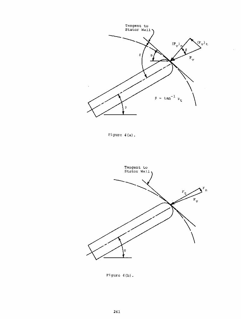
The tip force components, Ft and Fn, are shown acting at the geometr~c vane tip in Fig. 3. The actual point of contact between the vane and stator is shifted from the vane centerline. In the quadrant shown in Fig. 3, the contact is above the vane centerline, as shown in Fig. 4(a).
Actually, the force at the vane tip is caused by a normal force against the stator wall, (Fvl . Resolution of Fv into
t these components is shown in Fig. 4(a). As shown in Fig. 4(a), the frictional component of the vane tip force acts along the stator wall. It is proportional to the component of Fv normal to the wall,
i.e.
(Fv) =f.tt(Fv) t n
(l)
where f.lt is the coefficient of sliding friction for the two materials in contact at the stator wall. Thus, if either component of Fv is known, the other may be determined. The resultant tip force, Fv, can then be resolved into components
along and normal to the vane, Ft and Fn,
as shown in Fig. 4(b}.
The friction forces due to vane contact with the rotor are also proportional to the contact forces FR and FL. However, a distinct coefficient of friction, ~s is used, since the rotor material may be different from the stator material.
Both body forces, Fa and Fe, can be computed from the vane path geometry, if steady operation and constant tip contact are assumed. The axial force applied to assure vane tip contact, Fb, is a controllable quantity, and may be considered a parameter. Finally, the pressure forces, FpR and FPL' can be calculated from the fluid pressures in the adjacent volume segments and the exposed vane areas.
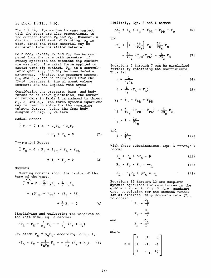
Considering the pressure, base, and body forces to be known quantities, the number of unknowns in Table 1 is reduced to three: FR, FL and Fv. The three dynamic equations may be used to solve for the remaining unknown forces. Using the free body diagram of Fig. 3, we have
Radial Forces
(2}
Tangential Forces
L F ::: 0 n FR + FPR - FL - Fl?L
+ F - F n c 0 (3}
Moments
summing moments base of the vane,
about the center of the
'+" L M ::: 0
+ ~ F = 0 2 c (4}
Simplifying and collecting the unknowns on the left side, Eq. 2 becomes
-FL - FR - ~ F ~ 1-ls t
Or, since Fn ~ ~tFt' according to Eq. 1,
F n (5}
253
Similarly, Eqs. 3 and 4 become
and
-FL + [1 - ~J F - ~ F T~s R T]..ls n
;~s (FPR-FPL} - T~s Fe
(6}
(7}
Equations 5 through 7 can be simplified further by redefining the coefficients. Thus let
(8}
a l (F + Fb} ~s a (9}
yl F - FPL + FPR c
~ (FPR - FPL} R,
F \)1 "" -T~s T~s c
1 - 2e 111 T]..l
s
and
1jJ 2R,
T]..ls (10)
With these substitutions, Eqs. 5 through 7 become
(11)
(12}
(13}
Equations 11 through 13 are complete dynamic equations for vane forces in the quadrant shown in Fig. 3, i.e. quadrant one. A solution for the unknown forces can be obtained using Cramer's rule [2], to obtain
FR DR
:; n and D
F n = o n
where
D
~[:1 1 _: l DL -1
\)1 -nl +1/!
{~ s _: l DR -yl
\)1 +lji
Evaluation of these determinants yi.elds the following solutions:
F n
-S(lji+nl) + (-vl+yllji) + a(ylnl+vl)
(1/!+n 1 ) + ( 1)!+1) + a(l-n1
)
(-y11j!+v1
) - S(lji+l) + a(v1
+y 1 )
-(lji+n 1 ) + (-lji+l) + a(1-n1
)
-<n 1 y1 +y1 > - 2v1 + S(l-n1 )
(1/J+n 1 ) + (-1/!+ll + a (l-n1 l
(14)
(15)
(16)
Equations 14 through .16 we.re derived for a vane in the upper right, or first quadrant of the ROVAC stator. From symmetry of the ROVAC stator, they also apply to the lower left, or third quadrant. All forces on a vane in the third quadrant have the same signs as those in the first quadrant. However, the force magnitudes are not the same, because the fluid pressure distribution is not symmetric.
In order to find solutions for FL, FR and Fn in the remaining two quadrants, consider the free body diagram of a vane in the second quadrant shown in Fig. 5. Here the vane excursion is decreasing. Thus the slot friction forces are directed outward along the vane. Consequently, the algebraic signs of these forces must change from one.quadrant to the next. Writing the dynamic equations for quadrants two and four, we obtain
Radial Forces
(17)
254
Tangential Forces
+ F + F = 0 n c (18)
Moments
Again summing moments about the center of the base of the vane,
'+" T T L M = 0 : - 2 flsFR + 2 flsFL
- iF n
0 (19)
Upon simplifying and collecting unknowns, Eqs. 17 through 19 become
and
F n
(20)
(21)
(22)
Equations 20 through 22 can be simplified further by redefining coefficients. Let
1 + 2e
n2 = -Tfls
With these substitutions, together with a, S and 1jJ defined by Eqs. 8, 9 and 10, Eqs. 20 through 22 become
FL + F -R aF = -S n
(23)
F -L F -R
F n = y2 (24)
F -L n2FR - 1/!Fn \)2 (25)
The solutions are again obtained using Cramer's rule, with the result that
Equations 26 through 28 complete the dynamic analysis of vane forces in either quadrants two or four. Once the friction forces are known, the work lost to friction is obtained as a product of the force times the distance it moves. We examine the actual use of the mathematical model in the next section.
USE OF THE MATHEMATICAL MODEL
To calculate numerical values for a given case, both sets of force equations, Eqs. 14 through 16 and 26 through 28, must be used twice to cover four quadrants of vane motion.
The following calculation procedure is used:
1. Choose an initial vane position.
2. Solve for the forces, FR, FL and (F ) in terms of geometric and v t flow parameters.
3. Evaluate the friction forces.
4. Move the vane through an increment of angle.
5. Evaluate the friction work lost as the product of friction force times distance moved.
6. Repeat steps 2 through 5 until a cycle is completed.
Although any degree of numerical accuracy could be obtained by taking small increments of angle and using precise integration techniques, the required calculations are complex and time consuming. Much of the complexity is due to the ROVAC geometry (all required geometric parameters are shown in Fig. 6). Due to the elliptical stator wall of the ROVAC machine and the curvature of the vane tip, the tip force vector changes direction continuously as the rotor turns. Thus all geometric quantities must be recalculated at each increment of rotor angle.
Additional problems are created by pressure
255
discontinuities at the stator ports. The thermodynamic analysis used in Ref. 3 was not capable of predicting transient pressure effects, since it was limited to steady state (or time averaged) fluid mechanics.
In view of these complexities and analytical uncertainties, a reasonable approach is to use the mathematical model to estimate the mean friction loss for a significant rotation, say one quadrant, or 90 degrees, and also to introduce additional simplifications in the orientation of the tip friction force. One method is to consider the stator profile as an ellipse of zero eccentricity (a circle). The mean Coriolis force, computed on the basis of the actual stator profile, can then be included as an additional normal force acting on the vane. This mean value approach was used in this work. The computing equations are developed next.
The quantities to be evaluated are Fa, F0 , the pressure forces, and the dimensions g and e. The remaining quantities, t, T, ~ , ~t and Fb are treated as known p~rameters for a given case.
Fa is the axial body force due to linear and centripetal acceleration of the vane. On a mean basis,
(29)
where Rm is the mean radius of the vane center of mass during one quadrant of motion, ~x is the vane excursion, and ~t is the time required for a vane to travel distance ~x in the rotor slot. w represents the radial speed of the rotor, and m is the mass of the vane.
The mean body force due to Coriolis acceleration is
~X F0
""m(2Vw) =o 2m ~t w (30)
The vane pressure forces, FPR and FPL are given as products of the pressures on either side of the vane and the exposed vane surface area. That is:
FPR (pR) (i - e)L
FPL (pL) (i - e)L
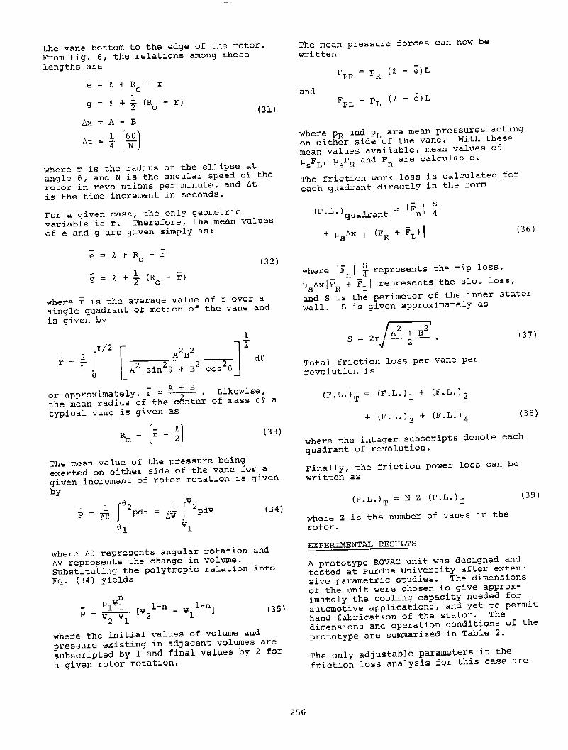
where PR and PL are the pressures on the right side and left side of the vane respectively. The quantity (i - e) represents the exposed vane width and L is the depth of the vane. Finally, g represents the distance from the vane bottom to the center of action of the pressure forces FPR and FPL' and e is the distance from
the vane bottom to the edge of the rotor.
From Fig. 6, the relations among these
lengths are
e == )!, + R r 0
)!, + 1 (R - r) g 2 0 (31)
t::.x == A - B
t::.t 1 [~OJ 4
where r is the radius of the ellipse at
angle 6, and N is the angular speed of the
rotor in revolutions per minute, and t::.t
is the time increment in seconds.
For a given case, the only geometric
variable is r. Therefore, the mean values
of e and g are given simply as:
g == t + ! (R - r> 2 0
(32)
where r is the average value of r over a
single quadrant of motion of the vane and
is given by
. l A+ B or approxlmate y, r ~ ---?-- •
the mean radius of the center
typical vane is given as
R m (r - ~)
Likewise, of mass of a
(33)
The mean value of the pressure being
exerted on either side of the vane for a
given increment of rotor rotation is given
by
(34)
where 1'16 represents angular rotation and
1'1¥ repres.ents the change in volume.
Substituting the polytropic relation into
Eq. (34) yields
n pl¥1
v2-vl p
[V 1-n _ v l-n1 2 1
( 35)
where the initial values of volume and
pressure existing in adjacent volumes are
subscripted by l and final values by 2 for
a given rotor rotation.
256
The mean pressure forces can now be
written
FPR == PR (£ - e)L
and FPL PL (£ - e)L
Where PR and pL are mean pressures acting
on either side of the vane. With these
mean values available, mean values of
~sFL, ~sFR and Fn are calculable.
The friction work loss is calculated for
each quadrant directly in the form
(F. L. ) d t == IFnI _4s qua ran
+ ~s/1x I (FR + FL)j (36)
where I:Fnl ~represents the tip loss,
~s1'1xi:FR + :FLI represents the slot loss,
and s is the perimeter of the inner stator
wall. S is given approximately as
s == 21T/¥-. Total friction loss per vane per
revolution is
(F. L.) T + (F. L.) 2
+ (F.L.) 3 + (F.L.) 4
(3 7)
(3 8)
where the integer subscripts denote each
quadrant of revolution.
Finally, the friction power loss can be
written as
(P.L.)T == N Z (F.L.)T
where Z is the number of vanes in the
rotor.
EXPERIMENTAL RESULTS
(39)
A prototype ROVAC unit was designed and
tested at Purdue University after exten
sive parametric studies. The dimensions
of the unit were chosen to give approx
imately the cooling capacity needed for
automotive applications, and yet to permit
hand fabrication of the stator. The
dimensions and operation conditions of the
prototype are summarized in Table 2.
The only adjustable parameters in the
friction loss analysis for this case are
Table 2. Dimensions and Operation Conditions of Prototype ROVAC System
Stator size, in Major axis Minor axis Length
Stator eccentricity, deg
Rotor vanes
Volume ratio
Inlet volume, . 3 ~n
Operating speed, rpm
Displacement, ft 3/min
Polytropic indexes Compression Expansion
Heat Exchanger Inlet port advancement, deg
Coefficient of vane friction
6.0 4.6 6.0
40
10
2.50
6.0
2000
70
1. 30 1. 35
7
0.11
Fb and the friction coefficients. (The pressure forces and body forces are obtained from the thermodynamic analysis and ROVAC geometry, respectively.) The friction coefficients ~ and ~ were taken directly from the data ~ublish~d by the manufacturer [4] of the polyimide vane material. The friction coefficient for this vane material is given nominally as 0.11.
Initially, we were concerned that a positive method of locating the vanes would be required to provide contact with the stator wall when the ROVAC unit was started. Operating experience showed that this was not necessary. Consequently, Fb was set equal to zero.
Because a large number of geometries were evaluated during parametric studies, the analytical results were programmed in FORTRAN IV. A complete listing of the program is contained in [3].
Predicted results are compared to experimental values in Table 3. The prototype tests showed that the ROVAC system behaved as predicted by the model. As shown by the data in Table 3, 5400 B/hr of cooling was delivered at 2000 rpm. The power input required was about 4.5 hp, for a COP of 0.45.
257
Table 3. Comparison of Predicted and Experimental Results
Cooling Capacity, B/hr
Overall COP
Horsepower per Ton of Refrigeration
DISCUSSION OF RESULTS
Predicted Measured
5296
0.42
11.7
5390
0.45
10.9
The use of mean values, although admittedly inexact, simplified the computer work tremendously. The results presented in Table 3 verify the validity of the analysis in a gross sense. For the case shown, the frictional work was about three times as large as the net thermodynamic work. Therefore the close agreement between calculated and measured results suggests that the friction losses were predicted closely.
A number of tacit assumptions were made in this analysis. For instance, FR and FL are assumed to act as line forces at the rotor slot upper edge and the vane bottom edge. In reality these forces will be distributed a finite distance along the side of the vane, depending upon the vaneto-slot clearance. Also the friction forces were assumed directly proportional to the normal forces. Neither of these assumptions is exact. Fluid dynamic effects at the vane tip and the vane-slot interface could be substantial due to the very large local velocity gradients during normal operation. One could argue that the hydrodynamic effects would tend to reduce the friction losses to some degree. However, treatment of this very interesting problem, is not included in the scope of this work.
Since friction losses are a large fraction of the total losses, performance of the ROVAC system could be improved if they were reduced. Wear at rubbing surfaces must also be considered in a final design e~a~u~t~on; w7ar_would also be reduced by m~n~m~z~ng fr~ct~on. New design concepts are currently being developed to minimize friction. Preliminary tests show encouraging results for these new designs. With them it should be possible to obtain actual coefficients of performance of 2 or above, by reducing friction 80 to 90 percent.
CONCLUSIONS
Development of a mathematical model to predict friction losses in rotary vane machines has been treated. Application of the model, using calculations for finite rotations, has suggested that friction losses can be predicted with acceptable
accuracy. The precision of the model could be improved by accounting for hydrodynamic effects and transient fluid dynamics. The numerical procedures could also be refined to take advantage of these improvements in the model. These extensions will provide the basis for future work.
ACKNOWLEDGMENTS
The experimental work reported in this paper was supported by the Purdue Research Foundation through an XR grant. Both this support, and the special assistance of Dr. F. N. Andrews and Dr. R. L. Davis, are gratefully acknowledged.
REFERENCES
1. Edwards, T. c. and McDonald, A.T., "ROVACS: A New Rotary-Vane Air-Cycle Air-Conditioning and Refrigeration System," SAE Paper Number 720079, 1972.
2. Wylie, c. R., Advanced Engineerin9 Mathematics, Second Edition. New York: McGraw-Hill, 1960, p. 32.
3. Edwards, T.C., "A Rotary Vane Open Reversed Brayton Cycle Air-Conditioning and Refrigeration System," Ph.D. Thesis, Purdue University, School of Mechanical Engineering, Lafayette, Indiana, June 1970. (A patent application has been filed by the Purdue Research Foundation, covering the ROVAC system. This thesis will be held confidential until the patent issues.)
4. "VESPEL - Precision Parts from duPont Polyimide," E. I. duPont de Nemours & Co., Inc., Plastics Division, Engineering Brochure 14-60614, pp. 5-6.