+ All Categories
Home > Documents > Analysis of Near-Infrared Phase Effects on Biometric Iris Data

Analysis of Near-Infrared Phase Effects on Biometric Iris Data

Date post: 17-Jan-2022
Category:
Upload: others
View: 2 times
Download: 0 times
Share this document with a friend
184
Brigham Young University Brigham Young University BYU ScholarsArchive BYU ScholarsArchive Theses and Dissertations 2006-12-07 Analysis of Near-Infrared Phase Effects on Biometric Iris Data Analysis of Near-Infrared Phase Effects on Biometric Iris Data Brady Roos Stevenson Brigham Young University - Provo Follow this and additional works at: https://scholarsarchive.byu.edu/etd Part of the Computer Sciences Commons BYU ScholarsArchive Citation BYU ScholarsArchive Citation Stevenson, Brady Roos, "Analysis of Near-Infrared Phase Effects on Biometric Iris Data" (2006). Theses and Dissertations. 1299. https://scholarsarchive.byu.edu/etd/1299 This Thesis is brought to you for free and open access by BYU ScholarsArchive. It has been accepted for inclusion in Theses and Dissertations by an authorized administrator of BYU ScholarsArchive. For more information, please contact [email protected], [email protected].
Transcript

Brigham Young University Brigham Young University

BYU ScholarsArchive BYU ScholarsArchive

Theses and Dissertations

2006-12-07

Analysis of Near-Infrared Phase Effects on Biometric Iris Data Analysis of Near-Infrared Phase Effects on Biometric Iris Data

Brady Roos Stevenson Brigham Young University - Provo

Follow this and additional works at: https://scholarsarchive.byu.edu/etd

Part of the Computer Sciences Commons

BYU ScholarsArchive Citation BYU ScholarsArchive Citation Stevenson, Brady Roos, "Analysis of Near-Infrared Phase Effects on Biometric Iris Data" (2006). Theses and Dissertations. 1299. https://scholarsarchive.byu.edu/etd/1299

This Thesis is brought to you for free and open access by BYU ScholarsArchive. It has been accepted for inclusion in Theses and Dissertations by an authorized administrator of BYU ScholarsArchive. For more information, please contact [email protected], [email protected].

ANALYSIS OF NEAR INFRARED PHASE EFFECTS

ON BIOMETRIC IRIS DATA

by

Brady R. Stevenson

A thesis submitted to the faculty of

Brigham Young University

in partial fulfillment of the requirements for the degree of

Master of Science

School of Technology

Brigham Young University

December 2006

BRIGHAM YOUNG UNIVERSITY

GRADUATE COMMITTEE APPROVAL

of a thesis submitted by

Brady R. Stevenson Each member of the following graduate committee has read this thesis and by majority vote has been found to be satisfactory. Date Gordon W. Romney, Chair

Date Barry Lunt, Master Member

Date Ronald F. Gonzales, Master Member

BRIGHAM YOUNG UNIVERSITY As chair of the candidate’s graduate committee, I have read the thesis of Brady R. Stevenson in its final form and have found that (1) its format, citations, and bibliographical style are consistent and acceptable and fulfill university and department style requirements; (2) its illustrative materials including figures, tables, and charts are in place; and (3) the final manuscript is satisfactory to the graduate committee and is ready for submission to the university library. Date Gordon W. Romney

Chair, Graduate Committee

Accepted for the School

Val D. Hawks Director

Accepted for the College

Alan R. Parkinson Dean, Ira A. Fulton College of Engineering and Technology

ABSTRACT

ANALYSIS OF NEAR INFRARED PHASE EFFECTS

ON BIOMETRIC IRIS DATA

Brady R. Stevenson

Department of Information Technology

Master of Science

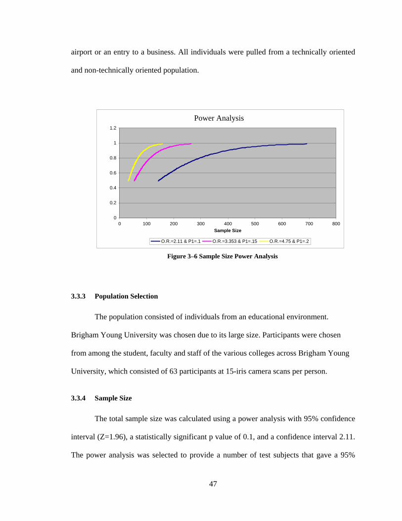
The purpose of this research is to ascertain potential iris scan data variations from

near infrared waves derived from fluorescent illumination. Prior studies of iris data

variances from infrared wave interference of halogen, incandescent, and sunlight with iris

cameras suggest that similar changes may exist under near infrared wavelengths from

fluorescent light. The concern is that the fluorescent energy emission may interfere with

the near infrared detection of an iris camera. An iris camera is used to measure human

eye characteristics known as biometrics. If such infrared emission is statistically

significant, then it can alter the validity of the iris scan data. The experiment utilized nine

hundred forty-five (945) scans from sixty-three (63) subjects. Measured results showed

increased heat from ambient fluorescent illumination does not statistically alter the

biometric readings of human eyes. The test results fail to reject that data loss will not

occur as heat is increased in the ambient fluorescent light source.

ACKNOWLEDGMENTS

The support of my committee has been a major factor in the development and

completion of this thesis. The professionalism and wisdom of Dr. Gordon W. Romney

has helped me finish my thesis. He has provided countless hours of feedback and support

to bring all the ideas together. Dr. Barry Lunt and Dr. Ronald Gonzales have been critical

to the validity of the research. Panasonic Corporation has alsogenerously contributed

licensing and Software Development Kits (SDK) to further this research.

I would also like to thank my wife, Laurie, for her countless hours of support and

advice. Her listening ear has been the reason for the ongoing efforts to complete my

thesis. Finally, I would like to thank Jake Merrill for the hours spent helping to code and

consult during the implementation process.

vii

TABLE OF CONTENTS

LIST OF TABLES ......................................................................................................... xiii

LIST OF FIGURES ........................................................................................................ xv

1 INTRODUCTION..................................................................................................... 1

1.1 Background......................................................................................................... 1

1.2 Problem Statement .............................................................................................. 6

1.3 Hypothesis .......................................................................................................... 7

1.4 Justification......................................................................................................... 7

1.5 Thesis Structure .................................................................................................. 8

1.5.1 Review of Literature ....................................................................................... 8

1.5.2 Methodology ................................................................................................... 9

1.5.3 Summary ......................................................................................................... 9

1.5.4 Conclusion ...................................................................................................... 9

1.6 Assumptions...................................................................................................... 10

1.7 Delimitations..................................................................................................... 10

1.8 Glossary of Terms............................................................................................. 11

2 REVIEW OF LITERATURE................................................................................ 13

2.1 Biometric Security Model................................................................................. 13

2.1.1 Data Collection ............................................................................................. 14

2.1.2 Data Transmission ........................................................................................ 15

2.1.3 Signal Processing .......................................................................................... 16

viii

2.1.4 Decision Subsystem ...................................................................................... 17

2.1.5 Biometric Security Model Summary ............................................................ 18

2.2 Biometric Technology ...................................................................................... 18

2.2.1 Fingerprint..................................................................................................... 19

2.2.2 Facial Recognition ........................................................................................ 19

2.2.3 Retinal Scanning ........................................................................................... 20

2.2.4 Iris Recognition............................................................................................. 20

2.2.4.1 Iris Image Capturing ..................................................................................... 21

2.2.4.2 Iris Feature Encoding.................................................................................... 22

2.2.4.3 Statistical Independence................................................................................ 23

2.2.5 Fingerprint Scanning..................................................................................... 24

2.2.6 Biometric System Elements .......................................................................... 24

2.2.6.1 Template Enrollment .................................................................................... 25

2.2.6.2 Template Creation......................................................................................... 26

2.2.6.3 Template Matching ....................................................................................... 26

2.2.7 Environmental Influences ............................................................................. 26

2.2.8 Alternative Iris Recognition Methods........................................................... 27

2.2.9 Iris Technologies Comparison ...................................................................... 27

2.3 Iris Technology and Retinal Technology.......................................................... 28

2.4 Security and Legal Issues ................................................................................. 29

2.4.1 Security Issues .............................................................................................. 29

2.4.2 Legal Issues................................................................................................... 30

2.5 Infrared Iris Technology ................................................................................... 30

2.5.1 Infrared Effects on Eyes................................................................................ 30

2.5.1.1 Cornea ........................................................................................................... 31

ix

2.5.1.2 Aqueous Humor ............................................................................................ 31

2.5.1.3 Iris ................................................................................................................. 32

2.5.2 Infrared Effects on Panasonic BM-ET300 Iris Camera ................................ 32

2.5.2.1 Infrared-to-Infrared Interference................................................................... 32

2.5.2.2 Infrared-to-Camera Interference ................................................................... 33

2.6 Iris Recognition Standards................................................................................ 34

2.6.1 Iris Image Interchange Format...................................................................... 34

2.6.1.1 Rectilinear Image Storage Format ................................................................ 34

2.6.1.2 Polar Image Specification ............................................................................. 35

2.6.2 Biometric Data Interchange Formats: Iris Image Data ................................. 35

2.7 Review of Literature Conclusion...................................................................... 35

3 RESEARCH PROCEDURES................................................................................ 37

3.1 Hardware Configuration ................................................................................... 37

3.1.1 BM-ET300 Iris Camera ................................................................................ 38

3.1.1.1 Issues Installing............................................................................................. 38

3.1.2 Iris Server...................................................................................................... 39

3.1.3 OOIBase32 Infrared Sensor .......................................................................... 40

3.1.4 Fluorescent Lamp.......................................................................................... 40

3.1.5 Photometer .................................................................................................... 41

3.2 Software Configuration..................................................................................... 42

3.2.1 Windows XP Professional Configuration..................................................... 42

3.2.2 BM-ES300E Server Installation ................................................................... 43

3.2.3 OOIBase32 Implementation ......................................................................... 43

3.2.4 BM-ET300 SDK Code.................................................................................. 44

3.2.4.1 Issues Installing............................................................................................. 44

x

3.3 Iris Capture Procedures..................................................................................... 45

3.3.1 Institutional Review Board (IRB) Approval................................................. 46

3.3.2 Sample Population ........................................................................................ 46

3.3.3 Population Selection ..................................................................................... 47

3.3.4 Sample Size................................................................................................... 47

3.3.5 Sample Characteristics.................................................................................. 48

3.3.6 Data Collection ............................................................................................. 49

3.3.6.1 Phase I ........................................................................................................... 49

3.3.6.2 Phase II.......................................................................................................... 50

3.3.7 Biometric Best Practices ............................................................................... 50

3.4 Methodology Summary .................................................................................... 51

4 DATA ANALYSIS .................................................................................................. 53

4.1 Phase I Analysis................................................................................................ 54

4.2 Phase II Analysis .............................................................................................. 54

4.2.1 Grouping 1 at Λ = 0 nm (intensity = 0), Benchmark .................................... 55

4.2.2 Grouping 2 at 700 nm Wavelength............................................................... 56

4.2.3 Grouping 3 at 820 nm Wavelength............................................................... 58

4.2.4 Grouping 1 and Grouping 2 Comparison...................................................... 58

4.2.5 Grouping 1 and Grouping 3 Comparison...................................................... 60

5 CONCLUSION AND RECOMMENDATIONS.................................................. 61

5.1 Conclusions....................................................................................................... 61

5.2 Assumptions and Delimitations Summary ....................................................... 64

5.3 Recommendations for Further Research........................................................... 65

REFERENCES................................................................................................................ 69

APPENDICES................................................................................................................. 73

xi

APPENDIX A. SDK SOURCE CODE.......................................................................... 75

APPENDIX B. DATA SAMPLES............................................................................... 131

APPENDIX C. STATISTICAL RESULTS................................................................ 153

xiii

LIST OF TABLES

Table 2-1: Biometric Device Comparison (Williams, Reich, 2003, pg. 1) ........................19

Table 2-2: Hamming Distance and False Match (Daugman, 2001, pg. 9) .........................24

Table 2-3: Scan Comparison between Iris Scanners...........................................................27

Table 3-1: Hardware Specifications....................................................................................39

Table 4-1: Grouping 1 at Λ = 0 nm (intensity = 0), Benchmark ........................................56

Table 4-2: Grouping 3 at 820 nm Wavelength ...................................................................57

xv

LIST OF FIGURES Figure 1–1 Light Absorption ..............................................................................................2

Figure 1–2 Cartesian Coordinates.......................................................................................3

Figure 1–3 Phase Errors......................................................................................................4

Figure 2–1 Ethereal Packet Capture ................................................................................. 17

Figure 2–2 Iris Code (Daugman, 2000) ............................................................................ 21

Figure 2–3 Integrodifferential Operators (Daugman, 2001, pg. 7)................................... 21

Figure 2–4 Monochromatic Iris and Iris Code at 35cm (Daugman, 2001, pg. 1)............. 23

Figure 2–5 Hamming Distances (Different / Same) (Daugman, 2001) ............................ 25

Figure 3–1 Panasonic BM-ET300 Iris Camera................................................................. 38

Figure 3–2 OOIBase32 Infrared Sensor ........................................................................... 40

Figure 3–3 Dimmable Fluorescent Lamp ......................................................................... 41

Figure 3–4 Davis Instrumentations Photometer ............................................................... 42

Figure 3–5 OOIBase32 Infrared Wave Reading............................................................... 44

Figure 3–6 Sample Size Power Analysis .......................................................................... 47

Figure 3–7 Sample Size Calculations ............................................................................... 48

Figure 3–8 Phase I and II Procedure................................................................................. 50

Figure 4–1 Data Analysis Summary ................................................................................. 59

Figure 5–1 Chi-square Analysis........................................................................................ 63

1

1 INTRODUCTION

Potential iris scan failures from near infrared waves from fluorescent illumination

have caused image distortion and data loss. The background, problem statement,

methodology, and analysis of iris image capture and iris code corruption in the biometric

security model are studied to determine potential implementation parameters and

limitations.

1.1 Background

A scanned output may be delineated as a bit stream of ones and zeros that may be

used to define the unique characteristics of an individual’s iris, also called an iris code.

This binary code is ultimately determined by the physical design of the iris, which is the

colorfully designed muscle encircling the hole in the center of the eye known as the pupil.

Furthermore, through genetics each iris develops its own ligaments, furrows, ridges,

crypts, rings, coronas, freckles, and zigzag collarettes. The color of the iris is resolved in

the anterior layer of the iris allowing for long wavelengths to be absorbed while shorter

wavelengths are reflected and refracted by the cornea and stroma (Daugman, 2001, pg.

1737).

2

The iris begins to develop during the third month of gestation and those genetic

patterns of design develop during the eighth month. During the development phase each

iris retains characteristics of its own identity separate and distinct from the other iris as

Figure 1–1 Light Absorption

well as from other people. This uniqueness is based on the randomness of iris designs

between each eye of one person as well as the eyes of another individual (Daugman,

2001, pg 1). Figure 1-1 illustrates the absorption of light while the pupil allows light to

the back of the eye known as the retina. Even those individuals of different genders

demonstrate statistical randomness as found in research at Orebro University in Sweden,

which states, “There were no qualitative genetic differences between males and females

(Larsson, Pedersen, Stattin, 2003, pg. 195).” The differences of irises were identified

through visual recognition either at social gatherings or at entrances of organizations.

The evolution of visual identification and authentication of people were common

biometric techniques until the technology evolved to digital format. As identification and

authentication continued to require a higher degree of secured permissions, using the

3

proper type of light as well as a proper amount of light became a critical issue to more

accurately identify images.

As each area of the iris image is projected, the Cartesian coordinate system

representing the return vector values of real and imaginary numbers are shown or

registered as a ‘1’or a ‘0’ in Figure 1-2. Quadrant one (top right) returns a 1 and 1 (1,1),

quadrant II (top left) returns a 0 and 1 (0,1), quadrant III (bottom left) returns 0 and 0

(0,0), and quadrant IV (bottom right) returns a 1 and a 0 (1,0). This is repeated 1,024

times until 2,048 bits are extracted equating to a 256-byte bit stream (Daugman, 2004, p.

3). This bit stream is the parameter that constitutes the ‘iris code.’

Figure 1–2 Cartesian Coordinates

The ‘iris code’ algorithm used by the Panasonic BM-ET300 iris camera, a limited

indoor monochromatic charged-coupled device (CCD), was implemented within this

study to evaluate bit stream variations from image distortion. The BM-ET 300 iris camera

has shown the ability to function between 770 nm and 850 nm wavelengths with minimal

image distortion from ambient lighting (Meyerhoff, 2005). Sunlight, incandescent light,

0, 0

0, 1 1, 1

1, 0

4

and halogen light were known to emit near infrared wavelengths, which caused phase

errors and data loss. Phase errors occur when a wave from one direction intersects a wave

from the opposite direction. The space between waves causes image distortion and bit

stream variation, or data loss. Figure 1-3 below illustrates phase errors from crossing

wavelengths of the iris camera and the fluorescent lamp. Ultimately, the iris images may

not be captured at a high quality because of phase errors, or wave distortion, of near

infrared between devices creating iris codes that may vary in statistical differentiation

from the original iris code template, also known as the hamming distance.

The statistical variation is a common occurrence in most biometric security

devices such as fingerprint, facial, retinal, and iris scanning currently challenge

environmental externalities during enrollment, storage, and recognition of individual

characteristics. Of all biometric security devices iris-scanning technology has continued

Figure 1–3 Phase Errors

to demonstrate accurate and non-obtrusive measures for most high security purposes.

Although, a couple of variables that were responsible for concerns with iris image capture

included phase errors as well as improper user interaction. Human interaction mistakes

suggested that incorrect subject use of the biometric iris camera caused image errors.

Iris CameraFluorescent Lamp

5

Biometric iris technology showed that phase errors affecting those few failures of the

overall need to be chronicled in research enrollment and recognition.

During the enrollment and recognition process, Panasonic Corporation stated that

errors from the near infrared spectrum of the sun, incandescent, and halogen lighting

interfered with iris cameras that emitted near infrared light, such as the Panasonic BM-

ET300 (Panasonic, 2004, BMET 300 User manual, pg. 2). Since fluorescent ballasts

generated ambient light from glowing elements, the near infrared wavelengths from heat

were produced by the mercury and argon elements (Kataoka and Atagi, 1997, pg. 243).

These environmental variables affected the image quality and ultimately the reading of

the iris code during authentication and identification. These types of interference have

caused corruption of the bit stream code that determined the iris scan.

Further errors were illustrated during biometric fingerprint research at Brigham

Young University (BYU). The researchers determined that a lack of subject training of

biometric devices created an environment where individuals were deterred from

effectively interacting with biometric devices. The lack of device understanding

ultimately affected the performance of the system potentially resulting in a negative

inference (Green, 2004, Chapter 1).

The Panasonic BM-ET300 iris camera, an indoor monochromatic charged-

coupled device (CCD), has the ability to interact with humans at the near infrared

wavelengths between 770 nm and 850 nm range (Meyerhoff, 2005). The accuracy and

convenience of the technology has worldwide applicability at airports, border crossings,

and other high security buildings. Furthermore, sunlight, incandescent light, and halogen

light are common in emitting near infrared wavelengths. The iris images may not be

6

captured at a high quality because of the phase errors, or wave distortion of the reflected

image, between devices creating iris codes that vary in statistical differentiation from the

original iris code template, also known as the hamming distance. The background light

sources emitted limited near infrared to prevent interference with the iris camera during

the recognition process.

During the process of recognition, a statistical analysis was performed to

determine the failure of a test of statistical independence, meaning a similarity between

the two different irises did not exist. This failure of statistical independence (p =. 01) was

guaranteed to pass every time for different irises since the degrees of freedom, or forms

of variations in the iris, were compared… approximately 249 degrees of freedom

(Daugman, 2004, pp. 3-6). The bit stream of the enrolled iris and the bit stream of the

recognized iris were applied by the use of the Boolean Exclusive-OR operator (XOR).

The XOR operator is used in this instance to determine discrepancies between any

corresponding vector values of zero (0) and one (1). The dissimilarity between the two

iris code bit streams is quantified in an error transmission term called Hamming Distance

(HD). The expected difference between two iris codes is expected to be 0.5, or a 50/50

chance, which is not enough to show similarity. As the fraction, or Hamming Distance,

comes closer to 0, then it is implied that it is extremely improbable for two different irises

to disagree in phase information, or bit stream sequencing (Daugman, 2004, pp. 3-6).

1.2 Problem Statement

Technically, the problem occurs when different infrared wavelengths in

fluorescent illumination changed the captured biometric parameters, which uniquely

described a given human iris. The iris image characteristics, when captured with no

7

external infrared lighting conditions, created a complete binary code template. When

captured at a subsequent recognition event with higher infrared wavelengths from

fluorescent illumination, the binary code differentiated from the original template. The

resulting algorithm continued to follow a cyclic process of scanning the iris in 0.15 mm

to 1.2 mm ranges to generate a bit stream representing the angle information of

quadrature wavelets. The angle information, also known as phase vectors (quadrant I, II,

III, IV), is used to assign pair bit values of a zero or a one, ultimately deriving a 256 bit

stream (Daugman, 2004, p. 3). Phase errors created from parallel phasing of infrared

waves from the fluorescent illumination with the infrared wavelengths of the BM-ET300

iris camera generated a different bit sequence. Ultimately, fluctuating iris codes caused

false acceptance or rejection readings from an iris image.

1.3 Hypothesis

As infrared wave frequencies increase (0 nm, intensity = 0 > x < 820 nm) in a

fluorescent light source, the digital iris image will remain unaffected.

1.4 Justification

Studies in the area of iris camera technology from John Daugman of the

University of Cambridge suggested that further research was needed in the environment

of iris image capture (Daugman, 2001, p. 12). The need for reliable and accurate iris

scans while using fluorescent illumination is the motivation for the research. When the

accuracy of an iris scanner is not sufficient for an operational environment,

implementation of the device is in question. The question of what fluorescent lighting is

required to achieve a given level of performance remains to be clearly answered. A

8

model that describes fluorescent illumination performance can provide information about

potential illumination options for implementation. The results of this research will

include a descriptive performance analysis of iris scanning within a fluorescent

illumination as the background light source. This model will address the viability of using

fluorescent illumination to achieve high accuracy iris scanning.

1.5 Thesis Structure

The structure contains the Review of Literature, Methodology, Summary, and

Conclusions. The Review of Literature establishes a working knowledge of the problem

statement, the Methodology outlines the process and procedures to replicate the study,

and the Summary organizes the data to be interpolated and the Conclusion analysis the

data and presents further research from this study.

1.5.1 Review of Literature

The research presented began with a review of literature used to establish a

working knowledge of biometric technology. Furthermore, the study has served to

develop eye technology as a highly accurate and stable means of identification and

authentication. The review continued its focus on iris technology including external

infrared wave interaction with infrared on iris cameras and on human subjects. Iris

standards will be presented in coordination with technical implementation, including

associations and issues with other biometric technologies. For the purpose of this project,

security concerns with iris scanning technology are observed as implied as a function of

near infrared wave interference.

9

1.5.2 Methodology

This methodology developed the procedural requirements of the research method

associated with the problem statement. Additionally, an outline of the process was

devised to implement a repeatable process. The theoretical approach of the research

method was reviewed and analyzed to normalize the iris data. This methodology covered

the five main areas of this research, namely: (1) determining technical as well as logical

requirements, (2) standardizing practices and procedures, (3) controlling constants and

variables, (4) obtaining human testing permission and subjects, and (5) analyzing

statistical results for feasibility analysis of identity management technology used within

environments demanding high security. The research method continued to normalize the

statistical results and establish a current baseline to determine further research.

1.5.3 Summary

The summary is a report of details and results of the all of the test scan performed.

Analyses of the results in coordination with the thesis research problem are presented and

meanings are interpreted through discussion. Final conclusions in this chapter are

presented to expand the reasoning and derivation of the compiled and separate results.

1.5.4 Conclusion

Following the summary, conclusions are extrapolated and continual research

methods are presented. The results will develop a benchmark to continue potential

research of iris data variances. This portion contains writing on further areas of study in

the field of iris technology development as well as subject interaction with current and

future iris technology.

10

1.6 Assumptions

The purpose of scanning each subject is to understand the importance of image

corruption during the process of capturing iris characteristics. Pederson and Stattin (2003)

of Orebro University in Sweden discussed that if not closely looked into, the iris may be

construed as the same from the left to the right eye as well as the same from one person

to another person. The relationship between irises of one person is called intra-

correlation; inter-correlation is the relationship between an eye of one person and an eye

of another person. The assumption statistically suggests that scanning similar people of

gender, race, or nationality would create reliable results similar to scanning subjects of

diverse gender, race, or nationality (Larsson, Pedersen, Stattin, Pg. 195, 2003). Therefore,

the data may be limited for collection from any person that may be solicited within the

university setting.

Image and data corruption through illumination would provide valuable

information for manufacturers as well as researchers in showing false positive or false

negative results. The iris capturing quantifies the effectiveness of fluorescent illumination

and indicates whether or not it was an effective means of illumination for the Panasonic

BM-ET300 iris camera. Furthermore, the results of the study could be applied to

Information Technology professionals implementing an iris biometric system. Panasonic

could use these results to continue develop iris cameras to function in all illuminations

levels of a given lighted room.

1.7 Delimitations

The following conditions are variables and were not statistically evaluated as

significant factors:

11

1. The sample size was limited to a university population. The research being

performed on a campus would not statistically be affected by changing

background light.

2. The university population is considered suitable for collection of the nine hundred

fifty-four (954) iris sample sizes. Eight hundred eighty-two (882) samples are

evaluated after outliers are removed from the sample.

3. Diversity of nationality, gender, and race are not necessary in conducting

thorough data collection of iris samples.

4. Reflection and refraction are elements of ambient surfaces and are part of the iris

camera readings.

5. Variables such as eyelash interference, eye dilation, and nationality are accounted

for in the algorithm of the BM-ET300 software.

1.8 Glossary of Terms

Biometrics: method of verifying an individual's identity based on measurement of the

individual's physical feature(s) or repeatable actions where those features and/or actions

are both unique to that individual and measurable.

FAR (False Acceptance Rate): measure of the likelihood that the biometric security

system will incorrectly accept an access attempt by an unauthorized user

FRR (False Rejection Rate): measure of the likelihood that the biometric security

system will incorrectly reject an access attempt by an authorized user

Failure to Enroll (FTE): the rate at which scans fail to enroll into a system database

BM-ET300 Iris Camera (Charged-Couple Device - CCD): small electronic camera

made out of a semiconductor material for storing electronic information

12

Hamming Distance: percentage of bits different from enrollment and identification

Iris: muscular diaphragm that controls the size of the pupil; it forms the colored portion

of the eye

Authentication: process of determining whether someone or something is, in fact, who

or what it is declared to be

Integrity: assurance that data has been sent by the original person

Identification: process of recognizing something or someone by remembering

Confidentiality: Assurance that the data has not been viewed by anyone other than the

person receiving it

Illumination: degree of visibility of the environment

Intensity = number of waves (counts)

Near-infrared (NIR): infrared part of the electromagnetic spectrum nearer to the visible

portion; wave frequencies from 700 nm to 1000 nm

Statistical Significance: probably true (not due to chance)

Wavelength (Lambda -Λ) = frequency of electromagnetic wave

13

2 REVIEW OF LITERATURE

The review of literature presents six developing positions found in literature to

substantiate the research problem. Furthermore, the published literature develops a

potential for interference existing between near infrared emitting devices. The reviewed

positions include the (1) biometric security and technology models, (2) iris technology

and retinal technology, (3) security and legal issues, (4) infrared and eyes, (5) infrared

and cameras, and (6) iris recognition standards. The study continues to present

instructive segments of biometric eye technology, the prior research of the problem, and

observations of ongoing research.

2.1 Biometric Security Model

Biometric security models are logical systems that provide architectures, policies,

and procedures that develop a sense of confidentiality, integrity, availability, and non-

repudiation (Panko, 2004, pg. 256). Biometrics, or the ‘measurement of life,’ is a means

to identify people and ultimately to authenticate the person’s claimed rights to gain

access within a particular security model. The use of biometrics for information

assurance does not always guarantee full identity protection, but does provide an

assertion at a reasonable degree that the people who access, originate, send, or alter

information on a system are who they claim to be (authentication), have the authority to

14

do whatever they are doing (authorization), and cannot avoid accountability for what they

are doing (non-repudiation).

Research at the University of Purdue suggests that a multidimensional model of

biometric security called ‘Biometric Architecture and System Security’ (BASS) provides

a level of security that will protect a networked organization (Leniski, Skinner, McGann,

Elliott, 2003, pg. 444). The model follows a system of checks and balances to ensure an

accurate decision upon completion of the process. Accordingly, the general biometric

security model relies on four sequential elements of assurance for accurate identification

and authentication.

The sequential process is listed below:

1. Data Collection

2. Transmission

3. Signal-Processing Subsystem

a. Feature extraction

b. Quality control

c. Pattern matching

4. Decision Subsystem

2.1.1 Data Collection

The data collection process receives the behavioral and physiological

characteristics of the scanned subject. These unique metrics are stored for future retrieval

of identification and authentication. This first step becomes critical resulting in data that

will either become a template, or the data will be measured for uniqueness against the

template. Changing background light is an ongoing issue during the time period data is

15

collected. Following procedures to ensure control of the light is needed to ensure reliable

data.

Because of the changing background illumination variables, ‘best practices’ are

important for network administrators. The administrators must adhere to a system of

policies to act or react to security attacks to biometric devices. Daugman (2004) suggests

that the ‘best practice’ is to have ‘Liveness Detection’ in iris recognition devices. Due

diligence, or the process of arriving at a solution, is critical at the moment of data

collection process in order to avoid unsecured or unauthenticated attacks (QinetiQ, 2004,

pg. 7). Following these best practices provides a standardized mean to yielding similar

biometrics parameters. Although procedures ensure the process is the same, the changing

environment is difficult to control.

The probability that two biometric measurements yield the same biometric

parameters as a true positive is highly unlikely due to variable background light. Since

the surrounding environment of the device is always changing, the results may deviate

each time a reading is taken (QinetiQ, 2004, pg. 3). These changing environmental

variables include heat (infrared light), visible light, and humidity. In order to fully utilize

the power of biometric measurement devices, complete understanding of the

surroundings is required for proper installation and use. Likewise, subject interaction may

affect the outcome of the scan from improper movements as well as changes in their

biological features (i.e. new glasses, disease, or eye damage) (Ackerson, 2006, pg. 1).

2.1.2 Data Transmission

Transmissions of iris data within some systems require the Internet for storage,

while others store straight to the hard disk drive. Ultimately, the transmission of iris data

16

is determined by the size of the system. This size element will then determine types of

data compression and packet structuring. The actual iris code, which can vary from 256

bytes to 512 bytes, is stored within the BM-ET300 iris camera and is only accessed from

a reference in the database (QinetiQ, 2004, pg. 5). The header, image, ‘Yes’ or ‘No’

decisions, and footers are the payloads for any iris data transmission.

When iris data is sent over the wires it follows normal protocols for the network.

The data presented in this research is performed over Ethernet and required network

protocols to ensure the data is correctly transmitted between device and server. Ethereal

data capture software illustrates the protocols used for transmission as seen in Figure 2-1.

The Ethernet connection between the device and the camera are set using TCP at 8030

and 1084. Such ports may be scanned, yet the iris code is never transferred over the

Ethernet connection and therefore, the iris camera must be hacked before the enrolled

subject’s identity can be captured.

2.1.3 Signal Processing

Signal processing provides the unique features of the subject pattern matching and overall

quality control to the processing server. The dispensation of the signals requires logical

hamming distance analysis to determine any variances among the bit string. Complete

control of bit sequencing is needed to maintain authentic bit sequencing. The Hamming

Distance, or the fraction of bits that differ between two binary strings, provides a

probability that the two bit strings are authentic or an imposter. The result of the logical

algorithm provides a clear decision of a ‘Yes’ or ‘No’ between the bit strings. Bit

variations above a 30% hamming distance gives a decided ‘Yes,’ or ‘1,’ indicating that

17

the bit streams are different; otherwise, the decided ‘No,’ or ‘0,’ is given that the bits are

similar (Daugman, 2000, pg. 2).

Figure 2–1 Ethereal Packet Capture

2.1.4 Decision Subsystem

The decision subsystem evaluates the returned data and provides a truth table

giving a false accept (FA), correct accept (CA), false reject (FR), or false accept (FA).

Although four possible return values are given, only two actions are taken: (1) accept (FA

& CA), or (2) reject (FR & FA) (Daugman, 2000, pg. 1). These simple truth values will

then tell the system that the next steps are to ‘accept’ with no further actions; ‘reject’ and

try over; or ‘reject’ and no further action (Leniski, Skinner, McGann, Elliott, 2003, pg.

445). Such a truth table provides a logical system for the iris server to provide accurate

processing when the subject is presented.

18

2.1.5 Biometric Security Model Summary

The biometric security model is an architecture that provides confidentiality,

authentication, availability, and non-repudiation at 1 in 1.5 billion odds of a false match.

During the process of the biometric security model, attacks and environmental alterations

may affect the odds of a false match within the system. Such variables pose a suggested

need for appropriate system design and security architecture to ensure reliability and

stability (Tao, 2002, pg. 7).

2.2 Biometric Technology

Biometric recognition is a process that implements the security model of identity

collection, storage, and decision-making. The technology provides a reliable and accurate

means to facilitate the identification and authentication of subjects to the system.

Reviewing Table 2-1 for live biometric methodologies will illustrate a comparative

analysis of the most common biometric techniques (Williams, Reich, 2003, pg. 1). Even

though the technologies have a high or very high accuracy, the ease of use and the

stability are variable; although, the False Acceptance Ratio varies from ‘Medium’ (1 out

of 100 FAR) to ‘Very High’ (1 out of 1,200,000 FAR).

The stability and accuracy of iris recognition presents itself as a proven method of

identification and authentication. The iris is the only internal organ of the human body

that may be viewed externally. Furthermore, the iris does not change over time unless

disease, injury, or damage occurs (Ackerson, 2006, pg.1).

19

2.2.1 Fingerprint

Fingerprint recognition is an interesting technique for identification since it is one

of the most commonly used biometric methods. Williams and Reich (2003) categorized

relative accuracy to other biometric devices in terms of ‘Very High (1 out of 1,200,000),’

‘High (1 out of 700 - 1000),’ ‘Medium (1 out of 100),’ and ‘Low (1 out of 50)’ as seen in

Table 2-1. Mary Hanson (2000) stated that the accuracy and results of fingerprint

scanning requires the experience of an expert in the United States. Other

Table 2-1: Biometric Device Comparison (Williams, Reich, 2003, pg. 1)

Device Stability False Acceptance Ratio Ease Fingerprint High High (1 out of 1,000) High Face Medium Medium (1 out of 100) Medium Retina High Very High (1out of 1.2Million) Low Hand Medium High (1 out of 700) High Iris High Very High (1out of1.2 Million) Medium

countries require a minimum, but not in the United States. Fingerprint biometric methods

demand physical contact between the biometric device and the subject. Such interactions

have developed a sense of insecurity and concern of subjects (Green, 2004, pg. 1).

2.2.2 Facial Recognition

Facial recognition is an emerging technology that has no need for interacting with

the subject. The trade-off of ‘High’ Stability and ‘Very High’ Accuracy of 1 out of

1,200,000 False Acceptance Ratio (FAR) suggests that biometric camera technology may

still be implemented with a ‘Medium,’ or 1 out of 100 FAR. Furthermore, identification

accuracy is ‘High’ at 1 out of 1000 FAR when the subject has a straight visual of their

20

face to the camera. If the angle of the image changes, then the stability and Ease of use

categories drop below a standard level of implementation. Continual development of this

technology reflects the sincere impetus to implement the technology in high traffic

environments.

2.2.3 Retinal Scanning

Retinal scanning is just as accurate and stable as iris scanning. Ease of use is low

since the subject is required to place their head into a strictly controlled position. The

camera takes an image of the back of the retina to map the blood vessels, which do not

change overtime (Ackerson, 2006). Implementation of this camera requires professional

training by ophthalmologists or optometrists. Using retinal scans; doctors are able to

determine disease or injury to the human optical network over time.

2.2.4 Iris Recognition

Iris recognition is a process utilizing two of the functions of information systems,

which include subject interaction and information technology. The subject presents their

eye to the camera and an image of the iris is captured. Software then executes an

algorithm to create a biometric iris code to either become a bit string template, or become

a bit string measurement to be compared against a previously captured template. The

process is critical in recognizing potential failures to the system and in developing an

environment suitable for stability and consistency. The bit stream in Figure 2–2 can

easily be changed when an external variable such as infrared light causes different phase

bits to be generated to a different resolution, thus abating from the original template

image (Daugman, 2004). The process of capturing the features of an iris consists of

21

algorithmic procedures starting with (1) iris image capturing, (2) iris feature encoding, (3)

statistical independence, and (4) ‘Yes’ or ‘No’ decision environments (Daugman, 2004,

pp. 2-9).

Figure 2–2 Iris Code (Daugman, 2000)

2.2.4.1 Iris Image Capturing

Capturing and recreating the human characteristics of the iris requires a

mathematically accepted algorithm. In Figure 2–3 Daugman provides one such algorithm

in an Integrodifferential mathematical operator to encompass the eye.

Max(r,x0,y0) | Gσ(r) * (∂/∂r) ∫ r,x0,y0 (I(x,y)/2π) ds | Figure 2–3 Integrodifferential Operators (Daugman, 2001, pg. 7)

The purpose of the operator is to estimate the pupil boundaries, the outer

boundary of the iris, and the radius of the iris. Execution of the operator determines the

circular edges of the each characteristic of the eye to single pixel exactitude (Daugman,

2004, pg. 2). The captured iris image is organized in a pattern to be parsed by the

algorithm, which will then derive the digital iris pattern.

22

Daugman (2003) has shown that his iris algorithm is highly accurate in stable

environments. External variables, however, such as background color, lighting, noise, and

weather are the potential problems for continuing research (Tao, 2002, pg. 7).

2.2.4.2 Iris Feature Encoding

The digital patterns are obtained through a phase-quadrant demodulation using 2D

Gabor Wavelets (Daugman, 1985, pg 1160-1169). Gabor wavelets diagram the

wavelengths in vectors of a Cartesian plane. Daugman researched the 2D Gabor wavelets

back in 1985 and 1988, before iris patterns were of any real significance for security

(Daugman, 1985 & 1988, pp. 1160-1169 & pp. 1169-1179). Since then his research has

applied the Gabor wavelets to iris patterns. According to Daugman (2001), “Local

regions of an iris are projected onto quadrature 2D Gabor wavelets, generating complex-

valued coefficients….”

The returning values are real and imaginary representing a zero (0) and a one (1)

as represented in black (zero) and white (1) in the upper left hand corner of Figure 2-4

below. Daugam (2004) states further, “The angle of each phasor is quantized to one of

the four quadrants, setting two bits of phase information. The process is iterated 1,024

times across the iris until 2,048 phase bits are sequenced making a 256-byte code for each

unique iris.

The amplitude of a wavelet is due to extraneous factors such as image contrast,

illumination, and camera gain, ultimately causing potential phase errors in differentiating

patterns. Furthermore, signal analysis shows the patterns are two-dimensional, and then

complete depictions of any image are possible (Lee, 1996, pg. 996). The depictions of

23

wavelengths are changed when acted on by another wave, often changing the frequency

and therefore, the data sequence of the signal.

2.2.4.3 Statistical Independence

Further studies of iris recognition have provided nearly 9.1 million samples for

statistical analysis. The iris samples offer assistance in identifying characteristics that

affect the uniqueness of each scan. When comparing a set of irises statistical assurance is

needed for a ‘Yes’ or ‘No’ decision. If two irises are different, then they will statistically

pass the test of independence. When they are the same, then they will fail the test of

independence, suggesting a hamming distance greater than 30% of the total bit stream

(Daugman, 2001, pg. 8).

Figure 2–4 Monochromatic Iris and Iris Code at 35cm (Daugman, 2001, pg. 1)

Table 2-2 below illustrates the power of the sample size in determining

statistically strong odds of a false match (Daugman, 2001, pg. 9). The probability has a

magnitude of a seven-fold increase at the 30% hamming distance indicating that this is a

point of statistical significance.

24

Table 2-2: Hamming Distance and False Match (Daugman, 2001, pg. 9)

HD Criterion Odds of False Match .28 1 in 1011 .29 1 in 13 billion .30 1 in 1.5 billion .31 1 in 185 million .32 1 in 26 million

2.2.5 Fingerprint Scanning

Fingerprint technology provides the easiest and most available security

applications of all biometric devices. With production increasing each year,

implementation becomes feasible to more companies. The algorithmic process is similar

to other technologies.

The finger is first placed on a scanner and an American National Standard (ANSI)

file format is generated and then placed into an image file. The image format is next set

to binary to create differentiation between minutiae points.

Appearing bifurcation, disappearing bifurcation, appearing ridge ending, and

disappearing ridge ending may now determine the four areas of a fingerprint minutia

(Green, 2005, pg. 54). The technology furthers the biometric paradigm of enrollment and

identification and authentication. Hamming Distance decision environment of similar or

different iris features.

2.2.6 Biometric System Elements

The algorithm of iris scanning handles the logical side of the biometric system.

The process requires three main elements in order for the system to come to a definitive

‘Yes’ or ‘No’ decision. Figure 2-5 below illustrates the limits of a definitive ‘Yes’ or

‘No’ decision. Some systems require multi-modal authentication such as fingerprint and

25

Figure 2–5 Hamming Distances (Different / Same) (Daugman, 2001)

hand geometry to ascertain one’s identity. Iris scanning provides a definitive result

because it represents one’s biochemical makeup more accurately than a fingerprint scan.

During the identification module subjects presents themselves to the scanner and this will

preclude the need to remember anything for authentication. The next three elements

establish the framework of a biometric system. These requisites are enrollment, template,

and matching.

2.2.6.1 Template Enrollment

Basic enrollment is the process of accumulating all the characteristics of the

presented subject and generating a template to be used at a later time. The typical

procedure involves the Panasonic BM-ET300 capturing four images during enrollment.

This process is the focus of the research in determining how external near infrared light

may affect the enrollment process. Furthermore, incorrect subject interaction has been

known to be a cause of errors during enrollment of the iris template (Murali, 2004).

26

2.2.6.2 Template Creation

Template creation is the process of the iris scanner to produce a bit sequence to

store for later matching. The template is stored locally on the device and a reference is

placed in the database to access the iris code from the BM-ET300 iris camera. The

placement of the ‘iris code’ on the camera is a means of multi-level security in case the

Iris Server is attacked. Proprietary devices, such as the Panasonic BM-ET300 iris camera,

are designed so that no one has access to the iris code (Meyerhoff, 2005).

2.2.6.3 Template Matching

The matching process is the comparison of bit streams in iris scanning. The bits

run through an algorithm where they are processed through an XOR function. The

number of dissimilar bits is compared and a Hamming Distance is calculated. The

process returns three potential failure conditions: (1) failure to enroll, (2) false match, (3)

false no match. Each one of these will cause the subject to retry the process causing

potential frustration and concern for a waste of time (Murali, 2004).

2.2.7 Environmental Influences

External variables that may affect the accuracy and reproducibility of biometric

devices are concerns that are constantly being addressed in order to increase the

usefulness of the biometric devices. Subject interaction with the device may be altered by

variables such as (1) Background color, (2) other faces, (3) lighting, (4) weather, and (5)

temperature. Research continues in the subject interaction and mobile iris scanning at

Purdue University (Elliot, 2006).

27

2.2.8 Alternative Iris Recognition Methods

Kang Ryoung Park (2005) of SangMyng University in Korea proposes a fast

method of capturing iris images based on narrow-view and wide-view iris cameras. Park

(2005) said, “Using the wide-view and narrow-view iris cameras, I also compute the

subject’s gaze position. This information is used for aligning the X-Y positions of the

subject’s eye, and I use the visible-light LED for the fake-eye detection algorithm.” This

method produces an illumination time of 480 milliseconds (ms) as compared to the older

technology of 1523 ms (Park, 2005, pg. 1). The Panasonic BM-ET300 currently produces

an illumination time of 200 ms during image capture (Panasonic User Manual, 2003, pg.

2). Alternative methods push Panasonic and other corporations to continue developing

quick and accurate biometric devices such as the BM-ET300.

2.2.9 Iris Technologies Comparison

The International Biometric Group conducted an “Independent Testing of Iris

Recognition Technology” to evaluate major products. Three iris scanners evaluated are:

(1) LG IrisAccess 3000, the (2) OKI IRISPASS WG, and the (3) Panasonic BM-ET300

iris camera (IBG, 2005). As seen in Table 2-3, the three scanners are shown with LG

IrisAcess and OKI IRISPASS WG performing at a higher FTE than the BM-ET300.

Table 2-3: Scan Comparison between Iris Scanners

Device FTE Scans LG IrisAccess 89.89% 3364

OKI IRISPASS WG 89.68% 3364 BM-ET300 83.32% 3364

28

2.3 Iris Technology and Retinal Technology

Iris and retinal scanning are distinctive in practice and use completely different

technologies to capture an image of a portion of the eye. Iris scanning utilizes general

camera technologies to capture the image. Unlike iris scanning, retinal scanning requires

the camera to be about three-quarters of inch from the eye lens (Hill, pg. 11). The

technology is considered to be more invasive than iris scanning.

Both of the optical technologies are considered to be the most secure biometric

devices. The human eye begins to quickly decay after death and, therefore, is difficult to

“fraudulently by-pass the biometric system (Hill, pg. 9).” Figure 2–5 compares the image

results of an iris scan and a retina scan. As viewed here, the image of the iris is taken in

front of the eye, while the image of the retina is taken in the back of the eye.

Additionally, the iris scan takes approximately one minute for full algorithmic

processing.

The retinal scan takes about 3-5 minutes for algorithmic processing. If the pupil is

not dilating enough, then the full retina may not be completely examined. Eye doctors

often dilate the pupil to gain full access to the back of the eye. The time it takes for the

pupil to constrict back to normal size is anywhere between 1-3 hours (Ackerson, 2006,

pg. 2). Both devices are subject to issues of disease or injury. John Ackerson (2006) said

that if a subject presented an injured or diseased eye, then potential for failure increased

(Ackerson, 2006). Since subject interaction is more intense than iris scanning it becomes

a medium ease of use as viewed in Table 2-1.

29

2.4 Security and Legal Issues

Daugman (2001) has provided a mathematical algorithm that has shown minimal

scan failures showing that it compares with retinal scanning, which is considered the

most secure optical method (Hill, 1990, pg.1). Legal legislation of iris scanning has not

surfaced an issue since volume identity testing has not been made on the technology.

Figure 2–5 Iris (Daugman, 2001, pg. 1) and Retinal Image (Ackerson, 2006)

2.4.1 Security Issues

Iris recognition currently is being used in jails and airports. Since the jails and

airports are passing people of different cities, states, and countries the people responsible

for security are unable to identify everyone, unless they have the subject’s iris template in

a database and they can scan and compare them upon arrival. The question follows, when

does the enrollment occur for the traveler? This may take considerable time, but with

security on the rise since the attacks on the United States on September 11, 2001, efforts

to implement such devices are on the rise (economis.com, 2001).

30

2.4.2 Legal Issues

Forensic scientists are the not interested in the technology as of yet and will not

make a push for it until it can be used on tissue that has began decay. Therefore, the

public sector has minimal use of it and only wants it for automatic authentication

purposes (de Hert, 2005, pg. 6-7). Legal issues would only come to fruition if the

technology infringed on fundamental rights, such as physical integrity and rights of

privacy. As of now, use of the technology has not triggered a need for legislation (de

Hert, 2005, pg. 7).

2.5 Infrared Iris Technology

Infrared is a unique portion of the electromagnetic spectrum that can affect

subjects as well as devices that emit similar wavelengths. Infrared effects on human eyes

and on iris cameras will be reviewed and discussed in relationship to the research

problem. The ability of the human eye to absorb light provides a means to capture the

necessary characteristics of a subject’s eye through an infrared camera.

2.5.1 Infrared Effects on Eyes

The front structures of the eye may be affected by infrared due to the immediate

contact to light. Such structures include the cornea, the aqueous humor, and the iris. The

outer region of the human eye absorbs different amounts of infrared at different points of

the eye. The ability to present a clear image of the features in the eye is critical during the

iris capturing process. As the wavelengths increase, the absorption of eye tissue moves

towards the front of the eye. Infrared exposure may cause damage to eye tissue and may

change physical features as well as potential iris scan data (Ackerson, 2006). Tissue in

31

each eye structure absorbs at different wavelengths, which may cause eye damage in the

future. The retina absorbs most of the infrared waves between 700 nm and 1000 nm.

Between 1000 nm and 1500 nm the lens and vitreous humor absorb most of the infrared.

As long as the infrared is not sustained for a long amount of time, then the effects on

vision will be minimal (Voke, 1999, pg. 22).

2.5.1.1 Cornea

As the Panasonic BM-ET300 iris camera emits infrared at wavelengths of 800

nm, the cornea threshold for damage is high. Infrared exposure of 800 nm between 1-10

minutes has shown tissue necrosis, or cell death, from 2-7 mm in depth (Journée-De

Korver, J.G., Oosterhuis, J.A., Van Best, J.A., and Fakkel, J., 2004). Fortunately, the

emission time for the infrared pulse of the Panasonic BM-ET300 is 200 ms (1/300 of 1

minute), which means the cornea can withstand potential long-term necrosis (Panasonic,

2003, pg. 33). The cornea protects the iris and the retina from externalities that may

damage the fundamental elements of the eye, ultimately preventing proper vision. The

cornea receives no nutrients from blood vessels and repairs itself through tears and the

fluid in the aqueous humor (thinkquest.org, 2006).

2.5.1.2 Aqueous Humor

The aqueous humor is similar to water and is not affected by infrared light.

According to Voke, any change to the aqueous humor suggests that damage occurs to the

lens, the cornea, or the retina (Voke, 1999, pg. 23). Conclusively, damage to the eye is

the cause of physical change to the humor (Ackerson, 2006).

32

2.5.1.3 Iris

The iris absorbs nearly half of all the infrared light between the range of 750 nm

and 900 nm, which is the range used by the Panasonic BM-ET300 iris camera

(Meyerhoff, 2005). Interestingly, the pigmentation of the eye determines levels of

absorption and presenting the necessary features and characteristics to the camera lens.

Since the BM-ET300 iris camera emits for only 200 ms, the actual absorption affects the

iris and ultimately evolves into necrosis (Voke, 1999, pg. 23).

2.5.2 Infrared Effects on Panasonic BM-ET300 Iris Camera

The emission of heat is a generating force in creating wavelengths called infrared.

The wavelength just below visible light, often called near infrared, usually ranges from

780 nm to 900 nm. The range is similar to the Panasonic BM-ET300 iris camera

(Meyerhoff, 2003). The camera uses the infrared light, which is just beyond visible light,

to prevent light aversion to the subject (usbyte.com, 2006).

2.5.2.1 Infrared-to-Infrared Interference

Near infrared (NIR) light, or heat, have characteristics that merge between visible

and the full infrared (IR) spectrum. As the light is projected on the object, it is then

illuminated just enough to see monochromatic features. Accordingly, “The amount of

light coming to the eye from an object depends on the amount of light striking the

surface, and on the proportion of light that is reflected (Adelson, 2000, pg. 1).”

Continued research has shown that interference between different objects such as

short-frequency lighting systems and infrared remote controls are caused by frequency

similarities, thus leading to phase errors. Furthermore, research from Universidade de

33

Aveiro in Portugal found that fluorescent lamps produce very strong interference with

infrared spectra extending up to the 1000 nm range. The ranges are unique to fluorescent

ballasts and iris cameras emitting infrared pulses between 780 nm and 900 nm

(Universidade de Aveiro, 2005). The reflected eye image develops a phase error with the

emitted infrared light from the fluorescent ballast and changes the picture as well as the

iris code between enrollment and authentication (Kwok-tin, 2003, pg. 1). Panasonic

shows that this distortion is unique to infrared, which is found in incandescent light,

halogen light, and sun light (Panasonic, 2003, pg. 16).

2.5.2.2 Infrared-to-Camera Interference

The frequency mixing with infrared light from fluorescent ballasts introduce

phase errors in iris recognition. Shozo Kataoka and Kaoru Atagi state, “Results gained by

more accurate analysis show that there is indeed a small quantity of infrared being

generated in the fluorescent lamp (Kataoka, Atagi, 1997, pg. 1).” They found that

infrared is prevalent from 780 nm all the way to 1050 nm, more than enough to

encompass the range of the Panasonic BM-ET300 iris camera. National Electrical

Manufacturers Association (NEMA) identifies two major sources of infrared emissions,

namely: (1) spectral lines from the inert gas fill near electrodes, the anode and cathode;

and (2) mercury lines from the main discharge or positive column. Accordingly, the first

few minutes of ballast operation produce in the 800 nm – 850 nm bandwidth range,

followed by a jump to about 1015 nm after five to ten minutes of operation (NEMA,

1999, pg. 6).

34

2.6 Iris Recognition Standards

The International Organization for Standardization (ISO) and the International

Electrotechnical Commission (IEC) along with International Committee for Information

Technology Standards (INCITS) of the American National Standard (ANSI) form a

specialized system of standardization. Occasionally, these organizations offer

contributions in the field of standardization with iris image capturing. Two standards that

are accepted through ANSI, ISO, and IEC are the Iris Image Interchange Format and the

Biometric Data Interchange Formats: Iris Image Data. The BM-ET300 iris camera

currently uses ANSI for its standard.

2.6.1 Iris Image Interchange Format

The Iris Image Interchange Format was officially approved on May 13, 2004. The

standard, according to INCITS, “contains a definition of attributes, a data record format,

sample records and conformance criteria (INCITS, 2004, Introduction).” The format

provides a couple of alternatives when using image interchange. These standards review

the areas of: (1) Image Compression, (2) Image Pre-Processing, (3) Iris Image Data

Record, (4) Iris Header Structures, and (5) Data Values in CBEFF Header (INCITS,

2004, pp. 1-15).

2.6.1.1 Rectilinear Image Storage Format

The Rectilinear Image Storage Format uses a raw, uncompressed array of values

that are specified in the ‘Joint Photographic Experts Group’ (JPEG) image standard. This

format suggests that images may be monochromatic or color with 256 or more intensity

35

levels (grey or per-color), and vary in size depending on field of view and compression

(INCITS, 2004, pg. 1).

2.6.1.2 Polar Image Specification

The record size of the ‘Polar Image Specification’ may be as small as 2 Kbytes

and be used in a raw or compressed format. This standard does require some extra pre-

processing steps before compression, but it provides a most useful compact data structure

with only iris information (INCITS, 2004, pg. 1).

2.6.2 Biometric Data Interchange Formats: Iris Image Data

The Iris Image Data standard is a specific standard that has been in a working

group staring March 20, 2003. The standard outlines specific values and formats of both

Rectilinear Image Storage Format and Polar Image Specifications (ISO & IEC, 2004, pp.

1-11). The specific areas of standardization include: (1) Image Compression, (2) Image

Pre-Processing, (3) Iris Image Biometric Data Block, and (4) Iris Header Structures.

2.7 Review of Literature Conclusion

This chapter started by introducing the biometric security model and its

importance to identity management. The biometric security model within iris scanning

technology provided a physical and logical system that ensured identity management was

handled properly and that the system and the confidentiality of human subjects were

protected. Legal and security issues were presented to discuss potential needs for

legislation to continue to protect the rights of the subjects and the rights of the managing

organization of the security system. Finally, the discussion furthered the argument of

infrared interference between subject and iris camera, subject and background light, and

36

background light and iris camera. A review of the published literature has revealed that a

potential for interference exists between near infrared emitting objects.

37

3 RESEARCH PROCEDURES

The methodology performed in conjunction with this research design involved

obtaining approval, evaluating variables, controlling test populations, creating strong

data, and maintaining biometric standards. The stated procedures continued to develop a

security model of confidentiality, integrity, availability, and non-repudiation.

Furthermore, the hardware and software configurations included those discussions used

to establish a consistent model of statistically strong data using the established

procedures. The statistical analysis of the population and sample size data was presented

as a condition offered to establish a satisfactory research method.

3.1 Hardware Configuration

Processing of iris images returned simple Boolean algebra expressed outputs. This

precludes the decision that specifications for the hardware were selected on the basis of

equipment compatibility. The informative variables collected were iris images, iris data,

and wavelength levels, five devices were used: (1) BM-ET300 iris camera, (2) Iris

Server, (3) OOIBase32, (4) fluorescent lamp, and a (5) photometer. Each device function

facilitated the process of iris image capture to meet what might be defined as a ‘normal’

environment. A normal environment was derived to be white & black ceilings and walls.

38

3.1.1 BM-ET300 Iris Camera

The BM-ET300 iris camera is proprietary and produced by the Panasonic Digital

Communications & Security Company (Panasonic). Also, an optional administration

software was supplied by Panasonic, specifically, (a) BM-ES300E, which handled

subject accounts, and (b) BM-ET300 iris camera Setup Software, which were used to

determine the configurations of the camera. The software modes included enrollment,

identification, video monitoring, voice positioning guidance, and live indicator detection.

Figure 3–1 illustrates the camera lens in the upper panel and the live indicator in the

lower panel.

Figure 3–1 Panasonic BM-ET300 Iris Camera

3.1.1.1 Issues Installing

Since the BM-ET300 iris camera required proper positioning, configuration, and

licensing, installation followed provided instructions. The parameters needed in preparing

for installation necessitated additional equipment to support the installation requirements.

The extra equipment included: (1) power cable, (2) LAN cable, and a (3) mountable rack.

39

The power cable was required to be UL style 1015 (AWG 14-18) or equivalent,

with a maximum distance of 10 m. The LAN cable was required to be UL style 1666,

CS-FT4 or equivalents using 10 Base-T/100 Base-TX (Category 5). The mountable rack

was hand made to fit a sitting position for a research subject. Since standing or sitting

was not relevant to the research, sitting was chosen for comfort. In normal usage at an

airport, for example, a subject was seated. Furthermore, the size of the rack is determined

by the testing environment and the administrators’ preferences. In the case of this

research it was designed to sit on a table so that a subject could sit comfortably for about

twenty minutes.

3.1.2 Iris Server

The data collection utilized one computer tower. Prior to configuring the server

software and application software, the hardware was selected to meet research

delimitations. The hardware products are found in Table 3-1.

Table 3-1: Hardware Specifications

Hardware Specification CPU Architecture X86 Based PC Celeron

Hard Drive ST36811A – Generic (6GB) Network Interface Card 3Com Etherlink XL 10/100 PU TXNIC (3C90SB-TX)

Computer Tower Dell OptiPlex GX100 CPU Speed 700 MHz

The research design configuration hardware was compatible with Windows XP

Professional and with adequate storage of at least 6 gigabytes. The hard disk drive also

40

needed to meet the standards of the operating system as well as the application, which

was determined to be six gigabytes by Panasonic.

3.1.3 OOIBase32 Infrared Sensor

The Ocean Optics, Inc. OOIBase32 hardware reads the wavelengths emitting

from a light source in its direct path. As seen in Figure 3-2, the sensor is placed in the

direct path of the light source to read the wavelengths that are in direct contact with the

camera. The device was designed to only be sensitive to wavelengths from 0-1000

nanometers (nm), which covered the spectrum relevant to this research.

Figure 3–2 OOIBase32 Infrared Sensor

3.1.4 Fluorescent Lamp

The research required the ability to change fluorescent illumination to include

certain levels of testing during the iris image capture of each subject. A fluorescent lamp,

which was dimmed by a rheostat switch, was selected to provide proper illumination

without having to change equipment during the procedure. The power for the dimmable

fluorescent lamp required an external power source (110V – 120V) to provide the

appropriate background fluorescent light.

41

The lamp was produced by Sunpark Electronics Corporation and was supplied to

Positive Energy for consumer distribution. The product is an alabaster shade, black with

55 watts 2C lamp. The lamp used protective glass that was tilted to provide a direct light

source to the camera as seen in Figure 3-3 below. No further settings and adjustments

were required to produce the necessary light. All glass windows were covered to ensure

the only light source was the lamp.

Figure 3–3 Dimmable Fluorescent Lamp

3.1.5 Photometer

To capture the light intensity in foot-candles, a photometer was placed in the

direct path of the fluorescent light source as seen in Figure 3-4. The reading provided the

necessary determination of intensity levels of each iris capture.

The photometer was produced by Davis Instrumentation and is an A.W. Sperry

version SLM-110. The photometer provided the necessary level measurements as the

wavelengths moved into the near infrared range.

42

Figure 3–4 Davis Instrumentations Photometer

3.2 Software Configuration

Capturing iris images and associated data required software compatible with

Windows XP Service Pack 2. The software was selected on the basic of platform

compatibility found in these applications: (1) BM-ES300E, (2) OOIBase32 “USB 2000”,

and the (3) BM-ET300 SDK. Each application worked in harmony within Windows XP

Professional to achieve the capture of required data for the research problem.

3.2.1 Windows XP Professional Configuration

Windows XP Service Pack 2 was installed using a full version from the university

Microsoft site license provided by the Brigham Young University School of Technology.

No further updates were obtained due to a lack of wire or wireless Internet connection.

All configurations were based on default settings in Windows XP Service Pack 2.

Microsoft Office was installed to facilitate the capturing of images and iris data.

All images are captured and copied to a Word document. No updates were installed and

all configurations were based on default settings of Microsoft Office.

43

3.2.2 BM-ES300E Server Installation

The BM-ES300E utilizes a package that includes software application, server

administration, and licensing. The proprietary nature of the software requires the

licensing to be purchased and installed separately.

The BM-ET300 application interface utilized the basic installation CD and did not

require additional services. The server administration software required an install

provided by Panasonic, which was sent through e-mail as part of its ongoing research

support. The install allows configurations to be set for voice guidance, enrollment, or

identification. Finally, the licensing CD was sent as further support from Panasonic as a

1,000-seat license. Since Panasonic was supporting the research, the license was sent

with no charge. Running the install disk with all defaults immediately licensed the

software.

3.2.3 OOIBase32 Implementation

The Brigham Young University Department of Physics provided the OOIBase32

light wave device that was used to analyze wavelengths up to 1000 nm. The chart in

Figure 3–5 illustrated the intensity on the X-axis and the wavelength on the Y-axis. The

intensity axis measured the number of times, called ‘counts,’ a wave came in contact with

the OOIBase32. Likewise, the wavelength axis measured the frequency of light waves

that came in contact with the OOIBase32. The near infrared readings began at about 700

nm and end around 900 nm wavelengths. The software was set to defaults and utilizes a

USB connection to read real-time light measurements. The measurements were evaluated

to determine statistically significant wavelengths for the research problem.

44

The data collected from these readings were used to determine readings from each

device that were the same. The correlation of the readings was then used to determine

phase errors that arose from wavelengths crossing paths also referenced as ‘phase errors.’

Figure 3–5 OOIBase32 Infrared Wave Reading

3.2.4 BM-ET300 SDK Code

The BM-ET300 Software Development Kit (SDK) was installed on Windows XP

Professional. The code was written in Visual Basic 6.0, version 8176 and developed in

Visual Studio 6.0. The function of the code was to streamline the process of capturing,

processing, and analyzing the images. The raw code can be located in Appendix B.

3.2.4.1 Issues Installing

The SDK code written in Visual Basic 6.0 was not available in the newer versions

of Visual Studio. Instead, Visual Studio 6.0 was installed to provide a functional

development environment. Many hours of testing and trial were needed to ensure that

data transfer and function processing were accurate.

45

In order for the SDK to interact with the BM-ET300 Iris Server, extra libraries

were placed in newly created folders on the root (commonly C:\) drive. Panasonic

provided the folders and files on the SDK compact disc (CD) for copying to the drive.

3.3 Iris Capture Procedures

To further the understanding of the effects of illumination factors and subject

interaction with the utilization of biometric iris technology, a basic statistical research

method was employed. The research in this study consisted of a process beginning with

the Internal Review Board Approval at Brigham Young University to use human subjects

and followed with a logical control method to establish independent variables and

constants. Next, a statistical method was used to evaluate the population selection,

sample characteristics, data collection, and best practices. Finally, groupings were

implemented to allow comparative analysis of the results.

Grouping 1 used a 0 nm (intensity = 0 counts) wavelength, Grouping 2 used a 700

nm wavelength, and Grouping 3 used an 800 nm wavelength. Grouping 1 was the

designated benchmark with Grouping 2 and Grouping 3 being the comparative data

groups. Since subject interaction resulted in a significant amount of failures during the

first capture, the scans were removed as statistical outliers

The methodology covered the major areas of variance in biometric iris

technology, namely: (1) confidentiality, (2) integrity, (3) availability, and (4) non-

repudiation. The procedures intended to provide a method to reconstruct the test of

variance with infrared light from an iris camera and infrared light from fluorescent

ballasts.

46

3.3.1 Institutional Review Board (IRB) Approval

The first step in the process was to obtain Institutional Review Board (IRB)

approval whereby iris images were obtained from subjects between the ages of 17 to the

age of 60. The purpose accomplished two things: (1) benefited Panasonic with further

understanding of illuminative affects on current iris technology, and (2) provided a

technical demonstration of biometric iris technology to further the researcher’s

knowledge in regards to externalities affecting iris cameras.

The process of obtaining the ‘use of subjects’ approval required several steps.

First, the Instiutional Review Board required a full introduction of the research problem

and the assurance that the human subjects were not subjected to a harmful environment.

Second, assurances were given that no preferential treatment or unintentional biases were

introduced in the individual’s participation in the sample. No incentives were available;

therefore, all tests were with complete subject cooperation. Each institution followed its

own procedures to remove liability from the researchers. Approval was obtained in

writing and was valid for one year.

3.3.2 Sample Population

The sample population was determined by a power study, which calculated the

probability that if a correlation existed, then the statistical significance test rejected the

null hypothesis for the alternative hypothesis.

The power analysis seen in Figure 3-6 below suggests that an appropriate sample

size is 704 scans (p<=.1). The majority of working subjects was between the ages of 18

and 30 and thus was able to use an iris biometric scanner in a public setting, such as an

47

airport or an entry to a business. All individuals were pulled from a technically oriented

and non-technically oriented population.

Power Analysis (Logistic Regression)

0

0.2

0.4

0.6

0.8

1

1.2

0 100 200 300 400 500 600 700 800Sample Size

O.R.=2.11 & P1=.1 O.R.=3.353 & P1=.15 O.R.=4.75 & P1=.2

Figure 3–6 Sample Size Power Analysis

3.3.3 Population Selection

The population consisted of individuals from an educational environment.

Brigham Young University was chosen due to its large size. Participants were chosen

from among the student, faculty and staff of the various colleges across Brigham Young

University, which consisted of 63 participants at 15-iris camera scans per person.

3.3.4 Sample Size

The total sample size was calculated using a power analysis with 95% confidence

interval (Z=1.96), a statistically significant p value of 0.1, and a confidence interval 2.11.

The power analysis was selected to provide a number of test subjects that gave a 95%

Power Analysis

48

confidence of statistical significance. The formula resulted in a minimum sample size (ss)

of at least seven hundred four (704) test subjects. The total numbers of completed tests

were 945 from a subject size of 63 people; which is 241 more samples than the required

sample size, ensuring a statistically significant result, or a chance that the results were

true. During the testing of each subject, fifteen scans were performed. Figure 3–7

illustrated the equation that determined the minimum sample size from the selected

population, which consisted of thirty thousand (30,000) students.

Figure 3–7 Sample Size Calculations

As seen above, Z=Z value (e.g. 1.96 for 95% confidence level), p = percentage

picking a choice, expressed as decimal (0.5 used for sample size needed), and

c=confidence interval, expressed as a decimal. The value returned represents the sample

of the full population to be analyzed.

3.3.5 Sample Characteristics

The samples in this study corresponded to a bigger populace, since the physical

nature of the eye was determined to be important to the research; although, a population

extending to other nationalities with different physical eye structures were evaluated

during Phase I (Daugman, 2001, pg.1). The sample came from a Brigham Young

University demographics “of 6 percent daytime international students, 26 percent were

from the Far East, 14 percent from South America, 14 percent from Canada, 13 percent

49

from Europe, 12 percent from Central America and Mexico, 7 percent from the Middle

East and 7 percent from Eastern Europe and Russia (BYU, 2006).” Furthermore, the

gender of the subjects was unrelated to the nature of the research problem. Larsson (et al)

determined that gender was not relevant to the iris patterns and thus, the results were not

compared to male or female subjects (Larsson, Pedersen, and Stattin, pg. 195, 2003).

3.3.6 Data Collection

Data collection required a process that gathered results efficiently and accurately.

The process involved two phases to ensure these specifications were achieved. Phase I

used 5 subjects at 20 scans each in order to find potential issues with the process. Phase II

used 63 subjects to collect the raw data of the research.

3.3.6.1 Phase I

Phase I was designed to sort out issues as well as delineated potential skewing of

data. First, the subject was placed in front of the camera and was explained the process by

which the images were captured. Second, the camera administrator started the image

capture, which took approximately 5 seconds. The software processed the image for the

next 45 seconds and returned a Boolean result of the image. Third, the administrator

captured the returned results and placed them into a spreadsheet. A copy of the image

was saved and placed on a backup hard drive to ensure were accessible. Fourth, after

each image is captured, the administrator changes the dimmable fluorescent lamp to a

new illumination level to introduce the infrared wavelength to the camera. A photometer

50

Figure 3–8 Phase I and II Procedure

read the intensity to determine it is the same illumination as other subjects at that specific

level. Finally, the process of the image capture is performed another fourteen times.

The complete procedure takes approximately 15 minutes, allowing for only 4

subjects (60 scans) per hour. The research involves 2 females (both Caucasian), and 3

males (2 Caucasian and 1 Asian). Although previous research indicated race and gender

did not affect the results, analysis of sample populations established that diversity was a

part of a ‘normal’ environment.

3.3.6.2 Phase II

Phase II began with the collection of raw research data. As mentioned in Chapter

2, best practices were followed in preparing the process for data collection. Since the

results returned successful and failed scans consistent to expectations, the study then

proceeded with the procedures outlined in Phase I.

3.3.7 Biometric Best Practices

The process followed the best practices of biometric data collection utilized by the

National Physical Laboratory (NPL) in England. The findings determined that four areas

should be evaluated when testing biometric equipment. These areas were: (1) planning

the evaluation, (2) data collection, (3) analysis, and (4) estimates. The baseline approach

51

of NPL provided a valuable tool to effectively and consistently derive repeatable results

to further the study of biometrics data capture (NPL, 2005).

3.4 Methodology Summary

The research process provided the means to obtain test approval, control external

factors, determined population selection, collected reliable data, and utilized best

practices from literature review found in chapter two of this study. The methodology

continued to outline the potential of security variance in biometric iris technology,

namely confidentiality, integrity, availability, and non-repudiation. Furthermore, the

procedures provided a method to reconstruct the test of variance with iris camera and

with infrared light from fluorescent ballasts.

53

4 DATA ANALYSIS

The data collected within the procedures of the previous chapter were explained

and analyzed. Furthermore, the data was organized into three groupings in order to

extrapolate and illustrate variance between the different levels of near infrared

wavelengths from fluorescent ballasts and in iris cameras. Grouping 1 data was referred

to as the benchmark, since the wavelength and intensity were set to zero. The results

from this grouping provided a standard for Grouping 2 and Grouping 3 to develop a

statistical comparison. Grouping 2 consisted of data collected at a near infrared

wavelength of 700 nm. This wavelength was relevant due to its common frequency in

external light sources (Panasonic, 2003). Grouping 3 evaluated a higher wavelength of

820 nm. This wavelength was used as the final comparison due to the fact that the BM-

ET300 iris camera used near infrared wavelengths in the 820 nm wavelength.

The analysis furthered the process of eliminating unnecessary variables in order to

achieve relevant data. As discussed in the previous chapter, the number of the data

sample were lowered to 882 due to the failure of the first scan, which still met the

required sample size of 704 scans. The metric used to produce an outcome measure for

each test subject was either a success or a failure, allowing for a comparative analysis of

success to failure variance. The results of the total scans were output to a spreadsheet

found in Appendix B.

54

4.1 Phase I Analysis

As mentioned in Chapter 3, Phase I was designed to determine potential issues,

which exposed a couple of anomalies in the data. The first issue was the physical makeup

of the subjects. An international student from Asia failed all 15 scans due to the physical

narrowness of his eyes. Since the camera required 70% of the iris to be exposed, the

image did not pass quality assurance and therefore, was rejected. Forcing the eyelids

open only yielded 3 successful scans out of 15. Another issue was the lack of training

with the device. Several of the subjects failed the first scan due to improper positioning of

the eyes and head. Since the other subjects had wider eye structures, scans 2 – 15

instituted greater success. To prevent misuse, the device was designed to talk to the

subject so they may position themselves properly. The misuse was attributed to the

inexperience of the subject and was treated as an outlier.

4.2 Phase II Analysis

Phase II gathered scans in order to determine points of failure with the image

created by the iris camera. As discussed in chapter 2, external near infrared waves cross-

phased with the internal near infrared waves of the iris camera. Pixel distortions from

phase errors lead to changing iris codes from the same subject. This research found that

the external near infrared waves were significant between Grouping 1 and Grouping 3

and insignificant between Grouping 1 and Grouping 2. A comparative review suggested

variance in statistical significance (p <= .01) between groupings. Additionally, the results

failed to reject the null hypothesis that the iris code will not change as near infrared

wavelength increases. Of the 945 tests performed (63 people at 15 scans each), 834 out of

945 scans were successful at 88.25% and 111 out of 945 scans were failures at 11.75%.

55

After the removal of the outliers, 882 tests (63 people at 14 scans each) 791 scans were

successful out of 945 scans at 89.68% and 91 scans out 945 scans were failures at

10.32%. A 1.43% difference occurred when the outliers were removed from the sample

group.

The research indicated that as the near infrared wavelength increases, the iris

camera failed. The results further countered that as infrared waves increased, the

performance of the camera increased. For example, a comparison between Grouping 1

and Grouping 2 showed a slight improvement in success rates. Grouping 1 had an

82.65% success rate while Grouping 2 had an 87.41% success. Furthermore, Grouping 3

had a success of 100%, which were an improvement of 12.59% from Grouping 2 and a

17.35% improvement from Grouping 1.

The results indicated that Grouping 1 and Grouping 2 generated similar success

rate and differed by 4.76% success. The variation between the two created a large enough

difference in success. A comparison between Grouping 1 and Grouping 3 revealed that as

the near infrared reached the 820 nm wavelength, the success of the device was a 100%.

The variation between Grouping 1 and Grouping 3 were statistically significant since the

success differed by 12.59%. The data suggested that near infrared light from fluorescent

tubes factored into the success of a scan when the wavelengths are between 0 nm

(intensity = 0 counts) and 820 nm wavelengths.

4.2.1 Grouping 1 at Λ = 0 nm (intensity = 0), Benchmark

Grouping 1 is benchmarked using zero near infrared wave intensity to examine

the changes as the near infrared intensity increases using the standard of methods and

procedures discussed in Chapter 3. Grouping 1 substantiates that 7 people are scanned 14

56

times each resulting in a specific success rate. The resulting benchmarks for success and

failure for the iris scans are shown in Table 4-1.

Table 4-1: Grouping 1 at Λ = 0 nm (intensity = 0), Benchmark ID Λ = 0nm (intensity = 0 counts) #Scans Success

1 0 14 14 2 0 14 11 3 0 14 9 4 0 14 14 5 0 14 13 6 0 14 14 7 0 14 6

The first scan of each subject had a 31.75% chance of failing as compared to the

other fifteen scans having the probability of failing at 6.35% and 12.70%. Such a high

failure rate introduced a variable of incorrect subject interaction. As a statistical outlier,

the first scan of each subject is removed from the 105 scans creating only a frequency of

fourteen to evaluate the scans that were only affected by the variable of near infrared

wavelengths. Each subject then is evaluated with 14 scans totaling 98 scans in the

grouping. As Table 4-1 shows, the success at the wavelength of 0 nm (intensity = 0

counts) of Grouping 1 had as small as 6 successful scans and as high as 14 successful

scans. The total of 81 successful scans produced an 82.65% success rate.

4.2.2 Grouping 2 at 700 nm Wavelength

Table 4-2 shows the success rate while holding the wavelength at the 700 nm

range. The external fluorescent heat is introduced to the camera causing a sudden

increase to the visible spectrum of light. Variations in successful scans are expected with

57

Table 4-2: Grouping 3 at 820 nm Wavelength ID Λ = Wavelength #Scans _ Success

8 700 14 10 9 700 14 10 10 700 14 12 11 700 14 14 12 700 14 14 13 700 14 12 14 700 14 14 15 700 14 13 16 700 14 14 17 700 14 14 18 700 14 1 19 700 14 14 20 700 14 14 21 700 14 13 22 700 14 14 23 700 14 12 24 700 14 14 25 700 14 14 26 700 14 7 27 700 14 14 28 700 14 13 29 700 14 14 30 700 14 14 31 700 14 14 32 700 14 14 33 700 14 13 34 700 14 12 35 700 14 14 36 700 14 13 37 700 14 14 38 700 14 13 39 700 14 14 40 700 14 7 41 700 14 13 42 700 14 5 43 700 14 13 44 700 14 5 45 700 14 13 46 700 14 14 47 700 14 14 48 700 14 14 49 700 14 10

such an increase, yet the observed results show that the success rate was at 87.45%.

Empirically, fluorescent illumination seems to not affect the iris camera. The data was

58

important in that it validated the empirical data and established quantitative strength of

success.

4.2.3 Grouping 3 at 820 nm Wavelength

Grouping 3 provided strong support that at the 820 nm wavelength from the

external fluorescent lamp provided 100% success. The probability of success was high

when the wavelength was at 820 nm with the BM-ET300 iris camera.

Table 4-3: Grouping 3 at 820 nm Wavelength ID Λ = Wavelength #Scans Success

51 800 14 14

52 800 14 14 53 800 14 14

54 800 14 14 55 800 14 14 56 800 14 14

57 800 14 14 58 800 14 14 59 800 14 14

60 800 14 14 61 800 14 14 62 800 14 14

63 800 14 14

4.2.4 Grouping 1 and Grouping 2 Comparison

The success rate of 87.41% with 635 scans in Grouping 2 showed a strong

correlation with Grouping 1 and its 82.65% success rate. Grouping 1 and Grouping 2 in a

t-test have an 18.50% chance of being truly different. Since the success of 82.65% and

the success of 87.41% between Grouping 1 and Grouping 2 was 4.76%, the two

groupings were insignificance.

59

With Grouping 1 being the benchmark, Grouping 2 showed the success

improvement as the near infrared wavelength increased. The resulting analysis of success

for the iris scans was shown below in Figure 4-1.

Wavelength and Intensity Success / Failure

0.00%

20.00%

40.00%

60.00%

80.00%

100.00%

120.00%

0 nm (intensity =0)

700 nm 800 nm

Wavelength (Intensity)

Figure 4–1 Data Analysis Summary

The success rate of 82.65% at the wavelength of 0 nm (intensity = 0 counts)

suggested that scan failures were not due to phase errors. Moving from 0 nm (intensity =

0 counts) to 700 nm showed an improvement of just fewer than five percent at 87.41%.

Failures actually decreased as the wavelength increased. When evaluating the successes

between the two groups, statistically the variation was insignificant and the results were

relatively similar. Ultimately, the two groupings were categorized together with similar

results.

60

4.2.5 Grouping 1 and Grouping 3 Comparison

The success rate of 100% with 588 scans in Grouping 3 showed a significant

correlation with Grouping 1 and its 82.65% success rate. Since the success and failure

variation between Grouping 1 and Grouping 3 was more than twice the amount of

Grouping 1 and Grouping 2, statistically the groupings were significantly different with a

t-test producing an 86.92% chance of the groupings being truly different. The difference

between the two grouping comparisons were statistically significant and suggests that as

wavelengths increase to a ‘normal’ illuminative setting the scan success will increase

Grouping 3 was used to compare variation between the success rates of grouping

1. With Grouping 1 being the benchmark, Grouping 2 showed the success improvement

as the near infrared wavelength increased.

The success rate of 100% at the wavelength of 820 nm suggested that scan

successes were not due to phase errors. Moving from 0 nm (intensity = 0 counts) to 820

nm showed an improvement of 4.76% at 87.41% success rate. Failures continued to

decrease as the wavelength increases. When evaluating the successes between the two

groupings, statistically the variation was significant, or not due to chance, and suggested

better illumination quality when the wavelengths were the same. The data provided

incremental value since waves from the fluorescent lamp produced waves at the 700 nm

range when the light was turned to the on position.

61

5 CONCLUSION AND RECOMMENDATIONS

5.1 Conclusions

The fundamental hypothesis was that as the wavelengths of fluorescent

illumination reach and enter near infrared, the cross phasing of incremental (0 nm,

intensity = 0 counts and 820 nm) wavelengths distorted the image and then corrupted the

iris data of the BM-ET300 iris camera. The intensity counts were the number of times a

wave came in contact with the OOIBase32, as referenced in section 3.2.3 of Chapter 2.

The hypothesis was tested in two phases, Phase I and Phase II, with procedures involving

three specified groupings, referenced as Grouping 1, Grouping 2, and Grouping 3.

Phase I tested the procedure and found several issues that have been statistically

accounted for as outliers. Phase II continued the testing of the raw data set to prepare for

the variation analysis among groupings.

Grouping 1 used a 0 nm (intensity = 0 counts) wavelength, Grouping 2 used a 700

nm wavelength, and Grouping 3 used an 820 nm wavelength. Grouping 1 was the

designated benchmark with Grouping 2 and Grouping 3 being the comparative data

groups. Since subject interaction resulted in a significant amount of failures during the

first capture, the scans were removed as statistical outliers.

Furthermore, for Grouping 1 of the research, samples of 98 scans were selected to

evaluate the infrared intensity of the camera with no external background near infrared

62

light. Grouping 1 was used to establish the benchmark of the research. The respondents

were then placed in front of the iris camera to evaluate the success at no wavelength of 0

nm (intensity = 0 counts). The results of Grouping 1 indicate that near infrared emitted

from the camera was not affected by complete blackness (Λ = 0 nm, intensity = 0 counts).

Without any external phasing of waves, the near infrared from the camera was sufficient

enough to capture the iris features and correctly used the algorithm to capture the

individual iris characteristics.

For Grouping 2 of the research, samples of 588 scans were used to scan for phase

errors of infrared light from the iris camera with near infrared light from external

fluorescent illumination. The test of success and failures were used to compare variation

between the success results of Grouping 1 and the success results of Grouping 2. The

results continued to suggest a minimal improvement of success from Grouping 1 to

Grouping 2. The results of the research indicated that the specific fluorescent infrared

wavelengths used in Grouping 1 and Grouping 2 did not statistically affect the success of

the iris camera. The success of the device improved from about 82% to about 89%, a 7%

improvement during the capturing process.

For Grouping 3 of the research, samples of 182 scans were used to determine

phase errors of infrared light from the iris camera with near infrared light from external

fluorescent illumination. The success and failures were used to compare variation

between the success results of Grouping 1 and the success results of Grouping 3.

Grouping 3 returned surprising results of 100%. Each scan was successfully captured

during the process. The results suggested an increased improvement of success from

Grouping 1 to Grouping 3. Furthermore, the results of the research indicated that the

63

specific fluorescent near infrared wavelengths used in Grouping 1 and Grouping 3 did

statistically affect the success of the iris camera. The success of the device improved

from about 82% to about 100%, an 18% improvement during the capturing process. This

success may be attributed to the ability of the subject to see the device and position them

correctly beginning with the first scan. As seen in Figure 5-1, a Chi-Square analysis

indicated that a 91.33% probability existed that the collected data (referenced in Chapter

4) fell within a 95% confidence interval.

Statistics of Order by Success/Failure

Statistic Frequency Probability --------------------------------------------------------- Chi-Square 13 0.9133 Likelihood Ratio Chi-Square 13 0.9128 Mantel-Haenszel Chi-Square 1 0.1658

Sample Size = 882

Figure 5–1 Chi-square Analysis

With a 95% confidence interval, the collected data indicated that the stated

hypothesis was false; the researcher failed to reject the null hypothesis. Increases in

failures were expected, but the data showed otherwise. These outcomes continued to

illustrate external variables such as illumination have an affect on the iris capturing

device. The fact that the capture process improved while increasing fluorescent infrared

wavelength suggested that illumination did affect the device. Higher levels of infrared

intensity seemed to improve the results. The illumination levels used settings ranging

from no infrared light to 820 nm wavelength.

64

5.2 Assumptions and Delimitations Summary

The data collection process developed the proposal that phase interference of

wavelengths changes the bit structure due to image quality. The specific assumption

observed through the research seemed false. After the statistical quantification of the

data, the analysis furthers the empirical data that an increase in fluorescent infrared seems

to not have a significant effect on the outcome of the image capture process. Of the first

scans, 31.75% of the participants of the research encountered subject mistake during the

first scan of the session. Only 11.11% of the subject’s encountered mistakes with scan 2 –

scan 15. With a 20% increase of mistakes from the first scan to the following scans, the

data was found to be an outlier in the final findings.

The delimitation in chapter one may have some effect on the data collected during

the image capture process. The first delimitation specifies that the study was limited to

participants from Brigham Young University (BYU). The size of the university

population is currently 30,000. Since gender does not play a role in the data, the

population is sufficient enough to support a sample size of 704 with 882 subjects from

the population.

The second delimitation states that the diversity of nationality, gender, and race are

not necessary in conducting thorough data collection of iris samples. The university

population is currently 91% Caucasian, while the other 9% are considered multicultural.

Brigham Young University currently has 4% Asian or Pacific Islander, while Native

American and African American's make up 5% of BYU's student population (byu.edu,

2006). For the purpose of this study gender was not analyzed.

65

The third delimitation states that the illumination reflection and refraction do not

affect the results of the iris camera since the camera works at the infrared wavelength.

Thus, the effects that reflection and refraction may have are natural and are assumed part

of the data.

The final delimitation stated that variables such as eyelash interference and eye

dilation are accounted for in the algorithm of the BM-ET300 software. Since the

algorithm accounts for the interference of eyelashes, the success and failures of such

features are a part of the collected data and the very nature of the research.

Furthermore, the subjects must be trained to use the Panasonic BM-ET300 so that

false rejections may be minimized and accurate readings of the device are the result.

Whether or not infrared of a higher intensity may affect the readings is currently

unknown. The research is focusing on maximum illumination within a normal

illuminated setting.

5.3 Recommendations for Further Research

The present research has identified areas for continued research that could expand

the usability of iris biometric technology. Further analysis should be undertaken with

regard to subject interaction during scans and enrollment. Finding methods to reduce the

failures during enrollment would be a valuable tool during iris technology design.

Furthermore, pushing the illumination spectrum of higher wavelengths of infrared

illumination would challenge the device and further the elemental issue underlying the

current research. Since shorter wavelengths are beyond the scope of this research and

may push the boundary of safety to eye tissue, it is deemed that continuing research may

not progress as rapidly as other issues.

66

Further research could be conducted in all industries focused upon this research,

such as training and technology. High security locations such as government, financial

institutions, and international airports could benefit from the development of iris scanning

technology. With security becoming multi-modal (iris, retina, hand, face, and etc.), or

multidimensional, a camera that handles these many types of biometric security could be

evaluated. Also, studying the potential to use visible light instead of infrared for the

device is an area that is currently being researched. This research implemented an

overview not specifically targeted individuals of specific age, gender, career, or

education.

Another area of research would be to analyze and compare cross illumination (i.e.

fluorescent, halogen, and incandescent illumination in the same room). Rooms are being

designed to use different types of light and therefore may be a viable issue when

implementing a security device that may be affected by the light. Other areas may include

researching devices that can account for external variables so that it may be used

outdoors. Continued research could be done in the area of developing filters to allow only

a certain amount of infrared to come in contact with the device while scanning outside.

Other issues made manifest during the process were the physical makeup of the

subjects. The study evaluated one Asian student and suggests nationality may or may not

affect the success of the device. Continuing research in the area of eye structures and

ways to accommodate for all eye structures should be reviewed.

Many areas of research have been presented and currently provide valuable

information for further research. The research indicates that the BM-ET300 iris camera

provides increasing success rates as the wavelength increases. Fluorescent infrared

67

appears to not be a factor when capturing an image in normal room conditions. The

future of infrared biometric technology remains unclear as security paradigms and needs

change. Although, biometric iris scanning comes from a visual identification to a digital

identification, the life cycle remains unclear as to when iris technology matures or dies.

However, it is evident that biometric iris technology must first continue to overcome

image-capturing barriers before it becomes a mainstream product in any setting and in

any environment.

69

REFERENCES

Ackerson, J. (2006). Interview by Brady R. Stevenson OD in Heber City, Utah – Doctor of Optometry / Optometry. 21 June, 2006.

Adelson, E. (2000). “Lightness Perception and Lightness Illusions.” The New

Cognitive Neurosciences, 2nd ed., M. Gazzaniga, ed. Cambridge, MA: MIT Press, 339.

ANSI (INCITS) (2003). “Iris Image Interchange Format.” ANSI INCITS 379-2004,

1-11.

byu.edu (2006). “Demographics.” Retrieved August 2006. http://unicomm.byu.edu/about/factfile/demo.aspx?lms=9.

Caltech.edu (2006). “Discovery of Infrared.” Retrieved August 2006.

http://coolcosmos.ipac.caltech.edu/cosmic_classroom/ir_tutorial/discovery.html.

Daugman, J. (2000). “Biometric Decision Landscapes.” 1. Daugman, J. (2001) “Anti-spoofing, Liveness Detection.” 16. Daugman, J. (2001). “Epigenetic randomness, complexity and singularity of human iris

patterns.” 1737. Daugman, J. (2001). “How Iris Scanning works.” 1-10. Daugman, J. (2001). “Iris Recognition.” American Scientist: Sigma Xi, 36(89) 4. 326. Daugman, J. (2001). “The Importance of Being Random: Statistical Principles of Iris

Recognition.” 1. Daugman, J. (2001). “The Importance of Being Random: Statistical Principles of Iris

Recognition.” 8.

Daugman, J. (2004). “How Iris Recognition Works.” IEEE Trans. CSVT 14(1), 21-30.

Daugman, J. (2004). University of Cambridge. Retrieved July 2006. http://www.cl.cam.ac.uk/~jgd1000/.

70

de Hert, P. (2005) “Biometrics: Legal Issues and Implication.” Retrieved August,

2006.http://cybersecurity.jrc.es/docs/LIBE%20Biometrics%20March%2005/LegalImplications_Paul_de_Hert.pdf#search=%22legal%20issues%20with%20iris%20scanning%22.

Economist.com (2001). “Watching You, Security Technology.” Retrieved August 24,

2006. http://www.economist.com/science/PrinterFriendly.cfm?Story_ID=787987.

Elliott, S.J. (2006). Biometric Standards, Performance, and Assurance Laboratory, Retrieved July 2006. http://www.biotown.purdue.edu/research/iris.html.

English, A., Means, C., Gordon, K., Goetz, K. (2006). “Biometrics: A Technology

Assessment.” Retrieved August 2006. http://www.bsu.edu/web/awenglish/SCHOOL/ITEDU_510/ta.html.

Green, N., and Romney, G.W. (2005). “Establishing Public Confidence in the Validity of Fingerprint Biometrics.” IEEE ITHET 2005 July, Dominican Republic. 54.

Hanson, M., "Fingerprint-based Forensics Identify Argentina's Desaparecidos," IEEE

Computer Graphics and Applications, vol. 20, no. 5, Sept/Oct, 2000. 7-10. Hill, R. (2005). “Retina Identification.” Retrieved January 2006. 11.

http://www.cse.msu.edu/~cse891/Sect601/textbook/6.pdf#search=%22Robert%20%22Buzz%22%20Hill%22.pdf.

International Biometric Group (2005). “ITIRT Final Report, Independent Testing of

Iris Recognition Technology.” NBCHC030114/0002. 14.

ISO & IEC (2004). “Biometric Data Interchange Formats: Iris Image Data.” ISO/IEC JTC 1/SC 37 N 504.

Journée-De Korver, J.G., Oosterhuis, J.A., Van Best, J.A. Fakkel, J. (1991). “Xenon

Arch Photocoagulator used for Transpupillary Hyperthermia.” Department of Ophthalmology, Leiden University Medical Centre, Leiden, and Department of Ophthalmology, Leiden University, Rijnsburgerweg 10, 2333 AA Leiden, The Netherlands. Documenta Ophthalmologica, Springer Netherlands, Volume 78, Numbers 3-4 / September 1991. 184.

Kataoka, S., Atagi, K. (1997). “Preventing IR interference Between Infrared Waves

Emitted by High-Frequency Fluorescent Lighting System and Infrared Remote Controls.” 1.

Kataoka, S., Atagi, K. (1997). “Preventing IR interference Between Infrared Waves Emitted by High-Frequency Fluorescent Lighting System and Infrared Remote Controls.” 243.

71

Kiruba, M. (2004). “Biometrics.” Ezine articles.

http://ezinearticles.com/?Biometrics&id=16097. Retrieved July 2005.

Kwok-tin, M. (2003). “Interference Problems of Fluorescent Lamps Operating on High Frequency Electronic Ballasts with Infrared Remote Control Equipment and Infrared Simultaneous Interpretation System.” Energy Efficiency Office, Electrical and Mechanical Services Department. 1.

Larsson, M., Pedersen, N., Stattin, H. (2003). “Importance of Genetic Effects for

Characteristics of the Human Iris.” 195. Lee, T.S. (1996) “Image Representation Using 2D Gabor Wavelets,” IEEE

Transactions on Pattern Analysis and Machine Intelligence, 18(10), 996.

Leniski, A.C., Skinner, R.C., McGann, S.F., Elliott, S.J. (2003). Security Technology 2003. Proceedings. IEEE 37th Annual 2003 International Carnahan Conference. Securing the Biometric Model, 444.

Library.thinkquest.org (2000). “Perception of your Vision, Cornea.” Retrieved August 2006. http://library.thinkquest.org/C005949/anatomy/cornea.htm.

Mansfield A.J., Wayman, J.L. (2002). “Best Practices in Testing and Reporting

Performance of Biometric Devices.” NPL Report CMSC 14/02 version 2.01 San Jose State University, 13.

Meyerhoff, T. (2005). Business Development Manager, Panasonic. Retrieved August

2004. http://www.findbiometrics.com/Pages/feature_panasonic.htm. National Electrical Manufacturers Association (1999). “Interaction of Infrared

Controls And Fluorescent Lamp/Ballast Systems in Educational Facilities.” A NEMA Lighting System Division Document. 6.

Panasonic (2003). “Iris Camera Operating Instructions, Model No. BM-ET300.”

Matsushita Electric Industrial Co. Ltd. 16, 33.

Panko, R. (2004). “Corporate Computer and Network Security.” Prentice Hall. Upper Saddle River, NJ, 256.

Park, K.R. (2005), Applied Optics, 44(5), 733.

QinetiQ (2003), White Paper. “Biometrics and Security – An Introduction,” 7.

QinetiQ (2003), White Paper .“Biometrics and Security – An introduction,” 3. Roethenbaugh, G. (1997). “NCSA Biometric Editor: Biometrics Explained.” 9.

72

Tao, W. (2002). “Identification Verification Methods – Biometrics.” 7.

Usbyte.com (2006). “The Electromaginc and Sound Spectra and Their Use for Retrieved August 2006. Communication.” http://www.usbyte.com/common/approximate_wavelength.htm.

Voke, J. (1999). “Radiation Effects on the Eye.” Optometry Today, 22-24. Williams, N.W., Reich, J. (2003). “Using Bio-Metrics in an Accelerator Personnel

Safety System.” 1

73

APPENDICES

75

APPENDIX A. SDK SOURCE CODE

Option Explicit Dim mFileSysObj As New FileSystemObject Dim mFile As File Dim mTxtStream As TextStream Dim filecounter As Integer Private m_oCn As Object Private m_oIris As Object Private Const M_SUCCESS As Long = 0 Private Const M_ERROR As Long = -1 Private Const M_WARNING As Long = -2 Private WithEvents LogEvent As ES300SDK.LogEvent Private Sub chkAllGet_Click() End Sub Private Sub cmdAccLogClear_Click() txtAccLogEvents.Text = "" End Sub Private Sub cmdAlmLogClear_Click() txtAlmLogEvents.Text = "" End Sub Private Sub cmdCamera_Add_Click() Dim oCamera As Object

76

Dim rtn As Long Dim sTemp As String Dim oError As Object On Error GoTo VB_Err Me.MousePointer = vbHourglass Set oCamera = CreateObject("ES300SDK.Camera") oCamera.CameraID = txtCameraID.Text oCamera.CameraName = txtCameraName.Text oCamera.IPAddress = txtIPAddress.Text oCamera.RecognitionMode = txtRecogMode.Text oCamera.ServerCertification = txtServerMode.Text oCamera.AudioMode = txtAudioMode.Text oCamera.GuidanceLanguage = txtGuidance.Text oCamera.Output1 = txtOutput1.Text oCamera.Output2 = txtOutput2.Text oCamera.LiveIndicator = txtLive.Text oCamera.SiteCode = txtSiteCode.Text oCamera.UserCode = txtUserCode.Text oCamera.PulseWidth = txtPulseWidth.Text oCamera.PulseInterval = txtPulseInterval.Text rtn = m_oCn.Camera_Add(oCamera) If rtn = 0 Then txtResult.Text = "Camera_Add method is successfully completed." Else sTemp = "Camera_Add method is unsuccessfully completed." For Each oError In m_oCn.Errors sTemp = sTemp & vbCrLf & "[Database.Errors]" 'Get error information from Error object sTemp = sTemp & vbCrLf & "Number : " & oError.Number sTemp = sTemp & vbCrLf & "Source : " & oError.Source sTemp = sTemp & vbCrLf & "Description : " & oError.Description sTemp = sTemp & vbCrLf Next txtResult.Text = sTemp End If Me.MousePointer = vbDefault Exit Sub

77

VB_Err: Me.MousePointer = vbDefault MsgBox Err.Description, , Err.Source End Sub Private Sub cmdCamera_Get_Click() Dim oCamera As Object Dim rtn As Long Dim sTemp As String Dim oError As Object Dim oGroup As Object On Error GoTo VB_Err Me.MousePointer = vbHourglass rtn = m_oCn.Camera_Get(txtCameraID.Text, oCamera) If rtn = 0 Then txtResult.Text = "Camera_Get method is successfully completed." txtCameraName.Text = oCamera.CameraName txtIPAddress.Text = oCamera.IPAddress txtRecogMode.Text = oCamera.RecognitionMode txtServerMode.Text = oCamera.ServerCertification txtAudioMode.Text = oCamera.AudioMode txtGuidance.Text = oCamera.GuidanceLanguage txtOutput1.Text = oCamera.Output1 txtOutput2.Text = oCamera.Output2 txtLive.Text = oCamera.LiveIndicator txtSiteCode.Text = oCamera.SiteCode txtUserCode.Text = oCamera.UserCode txtPulseWidth.Text = oCamera.PulseWidth txtPulseInterval.Text = oCamera.PulseInterval txtMode.Text = oCamera.ActionMode txtState.Text = oCamera.State lstAllGroups.Clear 'Get group information from Group object For Each oGroup In oCamera.Groups lstAllGroups.AddItem oGroup.GroupName Next

78

Else sTemp = "Camera_Get method is unsuccessfully completed." For Each oError In m_oCn.Errors sTemp = sTemp & vbCrLf & "[Database.Errors]" 'Get error information from Error object sTemp = sTemp & vbCrLf & "Number : " & oError.Number sTemp = sTemp & vbCrLf & "Source : " & oError.Source sTemp = sTemp & vbCrLf & "Description : " & oError.Description sTemp = sTemp & vbCrLf Next txtResult.Text = sTemp End If Me.MousePointer = vbDefault Exit Sub VB_Err: Me.MousePointer = vbDefault MsgBox Err.Description, , Err.Source End Sub Private Sub cmdCamera_Reset_Click() Dim rtn As Long Dim oError As Object Dim sTemp As String Dim sCameraID As String On Error GoTo VB_Err txtResult.Text = "" Me.MousePointer = vbHourglass sCameraID = txtCameraID.Text 'Camera_Reset rtn = m_oCn.Camera_Reset(sCameraID) If rtn = 0 Then txtResult.Text = "Camera_Reset method is successfully completed." Else sTemp = "Camera_Reset method is unsuccessfully completed." For Each oError In m_oCn.Errors sTemp = sTemp & vbCrLf & "[Database.Errors]"

79

'Get error information from Error object sTemp = sTemp & vbCrLf & "Number : " & oError.Number sTemp = sTemp & vbCrLf & "Source : " & oError.Source sTemp = sTemp & vbCrLf & "Description : " & oError.Description sTemp = sTemp & vbCrLf Next txtResult.Text = sTemp End If Me.MousePointer = vbDefault Exit Sub VB_Err: Me.MousePointer = vbDefault MsgBox Err.Description, , Err.Source End Sub Private Sub cmdCaptureRecog_Click() Dim oError As Object Dim lFileNumber As Long Dim bData() As Byte Dim rtn As Long Dim OnImage As Long Dim sTemp As String On Error GoTo VB_Err Me.MousePointer = vbHourglass txtResult.Text = "" If chkPicture.Value = 1 Then OnImage = 1 Else OnImage = 0 End If 'Iris image capturing for recognition 'This method is asynchronous. 'Refer StillCapture in database object for image condition. rtn = m_oCn.CaptureRecog(OnImage)

80

If rtn = 0 Then 'Successfully completed. txtResult.Text = "CaptureRecog method is successfully completed." lblCapture.Caption = "Iris image capturing" tmrCaptureStatus.Enabled = True Else 'Unsuccessfully completed. sTemp = "CaptureRecog method is unsuccessfully completed." For Each oError In m_oCn.Errors sTemp = sTemp & vbCrLf & "[Database.Errors]" 'Get error information from Error object sTemp = sTemp & vbCrLf & "Number : " & oError.Number sTemp = sTemp & vbCrLf & "Source : " & oError.Source sTemp = sTemp & vbCrLf & "Description : " & oError.Description sTemp = sTemp & vbCrLf Next txtResult.Text = sTemp End If Me.MousePointer = vbDefault Exit Sub VB_Err: Me.MousePointer = vbDefault MsgBox Err.Description, , Err.Source End Sub Private Sub cmdDistribute_Camera_Click() Dim rtn As Long Dim oError As Object Dim sTemp As String Dim sCameraID As String On Error GoTo VB_Err txtResult.Text = "" Me.MousePointer = vbHourglass sCameraID = txtCameraID.Text 'Distribute_Camera rtn = m_oCn.Distribute_Camera(sCameraID) If rtn = 0 Then

81

txtResult.Text = "Distribute_Camera method is successfully completed." tmrDistributeStatus.Enabled = True ElseIf rtn = -2 Then sTemp = "Distribute_Camera method is warning completed." For Each oError In m_oCn.Errors sTemp = sTemp & vbCrLf & "[Database.Errors]" 'Get error information from Error object sTemp = sTemp & vbCrLf & "Number : " & oError.Number sTemp = sTemp & vbCrLf & "Source : " & oError.Source sTemp = sTemp & vbCrLf & "Description : " & oError.Description sTemp = sTemp & vbCrLf Next txtResult.Text = sTemp tmrDistributeStatus.Enabled = True Else sTemp = "Distribute_Camera method is unsuccessfully completed." For Each oError In m_oCn.Errors sTemp = sTemp & vbCrLf & "[Database.Errors]" 'Get error information from Error object sTemp = sTemp & vbCrLf & "Number : " & oError.Number sTemp = sTemp & vbCrLf & "Source : " & oError.Source sTemp = sTemp & vbCrLf & "Description : " & oError.Description sTemp = sTemp & vbCrLf Next txtResult.Text = sTemp End If Me.MousePointer = vbDefault Exit Sub VB_Err: Me.MousePointer = vbDefault MsgBox Err.Description, , Err.Source End Sub Private Sub cmdDistribute_Flag_Click() Dim rtn As Long Dim oError As Object Dim sTemp As String Dim nState As Long Me.MousePointer = vbHourglass

82

txtResult.Text = "" lblDistribute.Caption = "" 'It is necessary to distribute the Iris Data. nState = m_oCn.Distribute_Flag If nState = 1 Then lblDistribute.Caption = "data distributed." ElseIf nState = 0 Then lblDistribute.Caption = "No data distributed." Else lblDistribute.Caption = "processing" End If Me.MousePointer = vbDefault End Sub Private Sub cmdGroup_Add_Click() Dim oGroup As Object Dim oCamera As Object Dim i As Integer Dim oUser As Object Dim oError As Object Dim rtn As Long Dim sTemp As String Dim sCameraID As String Dim pos As Integer On Error GoTo VB_Err Me.MousePointer = vbHourglass txtResult.Text = "" 'Create Group object Set oGroup = CreateObject("ES300SDK.Group") 'Set group information in Group object 'New group registration oGroup.GroupName = txtGroupName.Text sTemp = txtCameraID_G.Text Do While True pos = InStr(1, sTemp, ",", vbTextCompare) If pos = 0 Then Exit Do

83

Else sCameraID = Mid(sTemp, 1, pos - 1) Set oCamera = CreateObject("ES300SDK.Camera") oCamera.CameraID = sCameraID oGroup.Cameras.Add oCamera sTemp = Mid(sTemp, pos + 1, Len(sTemp) - pos) End If Loop rtn = m_oCn.Group_Add(oGroup) If rtn = 0 Then 'Successfully completed. txtResult.Text = "Group_Add method is successfully completed." Else 'Unsuccessfully completed. sTemp = "Group_Add method is unsuccessfully completed." For Each oError In m_oCn.Errors sTemp = sTemp & vbCrLf & "[Database.Errors]" 'Get error information from Error object sTemp = sTemp & vbCrLf & "Number : " & oError.Number sTemp = sTemp & vbCrLf & "Source : " & oError.Source sTemp = sTemp & vbCrLf & "Description : " & oError.Description sTemp = sTemp & vbCrLf Next txtResult.Text = sTemp End If Set oGroup = Nothing Set oCamera = Nothing Me.MousePointer = vbDefault Exit Sub VB_Err: Me.MousePointer = vbDefault MsgBox Err.Description, , Err.Source End Sub Private Sub cmdIrisRecog_Click() Dim rtn As Long Dim oError As Object Dim sTemp As String Dim sUserID As String

84

On Error GoTo VB_Err Me.MousePointer = vbHourglass txtResult.Text = "" 'Iris Recognition rtn = m_oCn.Iris_Recog(m_oIris, sUserID) 'Successfully completed. If rtn = 0 Then 'Recognition accepted sTemp = "Iris_Recog method is successfully completed." & vbCrLf sTemp = sTemp & " RecogOK UserID� F" & sUserID txtResult.Text = sTemp ElseIf rtn = 1 Then 'Recognition rejected sTemp = "Iris_Recog method is successfully completed." & vbCrLf sTemp = sTemp & " RecogNG" txtResult.Text = sTemp Else 'Unsuccessfully completed. sTemp = "Iris_Recog method is unsuccessfully completed." For Each oError In m_oCn.Errors sTemp = sTemp & vbCrLf & "[Database.Errors]" 'Get error information from Error object sTemp = sTemp & vbCrLf & "Number : " & oError.Number sTemp = sTemp & vbCrLf & "Source : " & oError.Source sTemp = sTemp & vbCrLf & "Description : " & oError.Description sTemp = sTemp & vbCrLf Next txtResult.Text = sTemp End If Me.MousePointer = vbDefault Exit Sub VB_Err: Me.MousePointer = vbDefault MsgBox Err.Description, , Err.Source End Sub Private Sub cmdIrisSetLeft_Click()

85

Dim rtn As Long Dim oError As Object Dim sTemp As String On Error GoTo VB_Err Me.MousePointer = vbHourglass txtResult.Text = "" If m_oIris Is Nothing Then 'Set iris data Set m_oIris = CreateObject("ES300SDK.Iris") End If m_oIris.UserID = txtUser(0).Text 'Set left iris data rtn = m_oCn.Iris_SetLeft(m_oIris) If rtn = 0 Then 'Successfully completed. txtResult.Text = "Iris_SetLeft method is successfully completed." Else 'Unsuccessfully completed. sTemp = "Iris_SetLeft method is unsuccessfully completed." For Each oError In m_oCn.Errors sTemp = sTemp & vbCrLf & "[Database.Errors]" 'Get error information from Error object sTemp = sTemp & vbCrLf & "Number : " & oError.Number sTemp = sTemp & vbCrLf & "Source : " & oError.Source sTemp = sTemp & vbCrLf & "Description : " & oError.Description sTemp = sTemp & vbCrLf Next txtResult.Text = sTemp End If Me.MousePointer = vbDefault Exit Sub VB_Err: Me.MousePointer = vbDefault MsgBox Err.Description, , Err.Source

86

End Sub Private Sub cmdIrisSetRight_Click() Dim rtn As Long Dim oError As Object Dim sTemp As String On Error GoTo VB_Err Me.MousePointer = vbHourglass txtResult.Text = "" If m_oIris Is Nothing Then 'Set iris data Set m_oIris = CreateObject("ES300SDK.Iris") End If m_oIris.UserID = txtUser(0).Text 'Set right iris data rtn = m_oCn.Iris_SetRight(m_oIris) If rtn = 0 Then 'Successfully completed. txtResult.Text = "Iris_SetRight method is successfully completed." Else 'Unsuccessfully completed. sTemp = "Iris_SetRight method is unsuccessfully completed." For Each oError In m_oCn.Errors sTemp = sTemp & vbCrLf & "[Database.Errors]" 'Get error information from Error object sTemp = sTemp & vbCrLf & "Number : " & oError.Number sTemp = sTemp & vbCrLf & "Source : " & oError.Source sTemp = sTemp & vbCrLf & "Description : " & oError.Description sTemp = sTemp & vbCrLf Next txtResult.Text = sTemp End If Me.MousePointer = vbDefault Exit Sub VB_Err:

87

Me.MousePointer = vbDefault MsgBox Err.Description, , Err.Source End Sub Private Sub cmdIrisVerify_Click() Dim rtn As Long Dim oError As Object Dim sTemp As String Dim sUserID As String Dim oIris As Object On Error GoTo VB_Err Me.MousePointer = vbHourglass 'Get iris data rtn = m_oCn.Iris_Get(txtUser(0).Text, oIris) If rtn <> 0 Then 'Unsuccessfully completed. sTemp = "Iris_Get method is unsuccessfully completed." For Each oError In m_oCn.Errors sTemp = sTemp & vbCrLf & "[Database.Errors]" 'Get error information from Error object sTemp = sTemp & vbCrLf & "Number : " & oError.Number sTemp = sTemp & vbCrLf & "Source : " & oError.Source sTemp = sTemp & vbCrLf & "Description : " & oError.Description sTemp = sTemp & vbCrLf Next txtResult.Text = sTemp Me.MousePointer = vbDefault Exit Sub End If txtResult.Text = "" 'Iris Recognition rtn = m_oCn.Iris_Verify(m_oIris, oIris) 'Successfully completed. If rtn = 0 Then 'Recognition accepted sTemp = "Iris_Verify is successfully completed." & vbCrLf sTemp = sTemp & " VerifyOK"

88

txtResult.Text = sTemp ElseIf rtn = 1 Then 'Recognition rejected sTemp = "Iris_Verify is successfully completed." & vbCrLf sTemp = sTemp & " VerifyNG" txtResult.Text = sTemp Else 'Unsuccessfully completed. sTemp = "Iris_Verify method is unsuccessfully completed." For Each oError In m_oCn.Errors sTemp = sTemp & vbCrLf & "[Database.Errors]" 'Get error information from Error object sTemp = sTemp & vbCrLf & "Number : " & oError.Number sTemp = sTemp & vbCrLf & "Source : " & oError.Source sTemp = sTemp & vbCrLf & "Description : " & oError.Description sTemp = sTemp & vbCrLf Next txtResult.Text = sTemp End If Me.MousePointer = vbDefault Exit Sub VB_Err: Me.MousePointer = vbDefault MsgBox Err.Description, , Err.Source End Sub Private Sub cmdLog_Delete_Click() Dim lKind As Long Dim lLogType As Long Dim ret As Long Dim i As Integer Dim sTemp As String Dim oLog As Object Dim oError As Object Dim rtn As Long Dim nCnt As Long On Error GoTo VB_Err Me.MousePointer = vbHourglass txtResult.Text = ""

89

If Option1(0).Value = True Then lLogType = 0 'Access Log ElseIf Option1(1).Value = True Then lLogType = 1 'Alarm Log Else lLogType = 2 'System Log End If If chkLogID.Value = 1 Then lKind = 0 Else lKind = 1 End If If lKind = 0 Then rtn = m_oCn.Log_Delete(lLogType, lKind, Text1(2).Text, "") Else rtn = m_oCn.Log_Delete(lLogType, lKind, 0, Text1(2).Text) End If If rtn = 0 Then 'Successfully completed. sTemp = "Log_Delete method is successfully completed." & vbCrLf Else 'Unsuccessfully completed. sTemp = sTemp & "Log_Delete method is unsuccessfully completed." For Each oError In m_oCn.Errors sTemp = sTemp & vbCrLf & "[Database.Errors]" 'Get error information from Error object sTemp = sTemp & vbCrLf & "Number : " & oError.Number sTemp = sTemp & vbCrLf & "Source : " & oError.Source sTemp = sTemp & vbCrLf & "Description : " & oError.Description sTemp = sTemp & vbCrLf Next End If txtResult.Text = sTemp Me.MousePointer = Default Exit Sub VB_Err: Me.MousePointer = vbDefault MsgBox Err.Description, , Err.Source

90

End Sub Private Sub cmdLogEvent_Set_Click() Dim rtn As Long Dim sTemp As String Dim oError As Object Set LogEvent = CreateObject("ES300SDK.LogEvent") 'Set LogEvent object rtn = m_oCn.LogEvent_Set(LogEvent) If rtn = 0 Then 'Successfully completed. txtResult.Text = "LogEvent_Set method is successfully completed." ElseIf rtn <> 0 Then 'Unsuccessfully completed. sTemp = "LogEvent_Set method is unsuccessfully completed." For Each oError In m_oCn.Errors sTemp = sTemp & vbCrLf & "[Database.Errors]" 'Get error information from Error object sTemp = sTemp & vbCrLf & "Number : " & oError.Number sTemp = sTemp & vbCrLf & "Source : " & oError.Source sTemp = sTemp & vbCrLf & "Description : " & oError.Description sTemp = sTemp & vbCrLf Next txtResult.Text = sTemp End If End Sub Private Sub cmdLogEvents_Start_Click() Dim rtn As Long Dim sTemp As String Dim oError As Object Dim LogKind As Long On Error GoTo VB_Err 'Start LogEvent If Option1(0).Value = True Then LogKind = 0 ElseIf Option1(1).Value = True Then

91

LogKind = 1 Else LogKind = 2 End If rtn = m_oCn.LogEvent_Start(LogKind) If rtn = 0 Then 'Successfully completed. txtResult.Text = "LogEvent_Start method is successfully completed." ElseIf rtn <> 0 Then 'Unsuccessfully completed. sTemp = "LogEvent_Start method is unsuccessfully completed." For Each oError In m_oCn.Errors sTemp = sTemp & vbCrLf & "[Database.Errors]" 'Get error information from Error object sTemp = sTemp & vbCrLf & "Number : " & oError.Number sTemp = sTemp & vbCrLf & "Source : " & oError.Source sTemp = sTemp & vbCrLf & "Description : " & oError.Description sTemp = sTemp & vbCrLf Next txtResult.Text = sTemp End If Exit Sub VB_Err: MsgBox Err.Description, , Err.Source End Sub Private Sub cmdLogEvents_Stop_Click() Dim rtn As Long Dim sTemp As String Dim oError As Object Dim LogKind As Long On Error GoTo VB_Err 'Stop LogEvent If Option1(0).Value = True Then LogKind = 0 ElseIf Option1(1).Value = True Then LogKind = 1 Else LogKind = 2

92

End If rtn = m_oCn.LogEvent_Stop(LogKind) If rtn = 0 Then 'Successfully completed. txtResult.Text = "LogEvent_Stop method is successfully completed." ElseIf rtn <> 0 Then 'Unsuccessfully completed. sTemp = "LogEvent_Stop method is unsuccessfully completed." For Each oError In m_oCn.Errors sTemp = sTemp & vbCrLf & "[Database.Errors]" 'Get error information from Error object sTemp = sTemp & vbCrLf & "Number : " & oError.Number sTemp = sTemp & vbCrLf & "Source : " & oError.Source sTemp = sTemp & vbCrLf & "Description : " & oError.Description sTemp = sTemp & vbCrLf Next txtResult.Text = sTemp End If Exit Sub VB_Err: MsgBox Err.Description, , Err.Source End Sub Private Sub cmdOpen_Click() Dim i As Integer Dim oError As Object Dim rtn As Long Dim sTemp As String filecounter = 0 On Error GoTo VB_Err Me.MousePointer = vbHourglass txtResult.Text = "" If m_oCn Is Nothing Then 'Create Database object Set m_oCn = CreateObject("ES300SDK.Database") End If

93

'Connect to database rtn = m_oCn.Connect(Text1(0).Text, Text1(1).Text) If rtn = 0 Then 'Successfully completed. sTemp = "Connect method is successfully completed." 'Get value from Database object sTemp = sTemp & vbCrLf & "ConnectUser = " & m_oCn.ConnectUser sTemp = sTemp & vbCrLf & "State = " & m_oCn.State sTemp = sTemp & vbCrLf & "Version = " & m_oCn.Version txtResult.Text = sTemp Else 'Unsuccessfully completed. sTemp = "Connect method is unsuccessfully completed." For Each oError In m_oCn.Errors sTemp = sTemp & vbCrLf & "[Database.Errors]" 'Get error information from Error object sTemp = sTemp & vbCrLf & "Number : " & oError.Number sTemp = sTemp & vbCrLf & "Source : " & oError.Source sTemp = sTemp & vbCrLf & "Description : " & oError.Description sTemp = sTemp & vbCrLf Next txtResult.Text = sTemp End If Me.MousePointer = vbDefault Exit Sub VB_Err: Me.MousePointer = vbDefault MsgBox Err.Description, , Err.Source End Sub Private Sub cmdClose_Click() Dim rtn As Long Dim oError As Object Dim sTemp As String On Error GoTo VB_Err txtResult.Text = "" Me.MousePointer = vbHourglass

94

'Release database rtn = m_oCn.Disconnect If rtn = 0 Then txtResult.Text = "Disconnect method is successfully completed." Else sTemp = "Disconnect method is unsuccessfully completed." For Each oError In m_oCn.Errors sTemp = sTemp & vbCrLf & "[Database.Errors]" 'Get error information from Error object sTemp = sTemp & vbCrLf & "Number : " & oError.Number sTemp = sTemp & vbCrLf & "Source : " & oError.Source sTemp = sTemp & vbCrLf & "Description : " & oError.Description sTemp = sTemp & vbCrLf Next txtResult.Text = sTemp End If Me.MousePointer = vbDefault Exit Sub VB_Err: Me.MousePointer = vbDefault MsgBox Err.Description, , Err.Source End Sub Private Sub cmdGet_Logs_Click() Dim lAllGet As Long Dim lLogType As Long Dim ret As Long Dim i As Integer Dim sTemp As String Dim oLog As Object Dim oError As Object Dim rtn As Long On Error GoTo VB_Err Me.MousePointer = vbHourglass txtResult.Text = "" If Option1(0).Value = True Then lLogType = 0 'Access Log

95

ElseIf Option1(1).Value = True Then lLogType = 1 'Alarm Log Else lLogType = 2 'System Log End If If chkAllGet.Value = 0 Then lAllGet = 0 'Get log with specified time Else lAllGet = 1 'Get all log information End If 'Get log information 'Refer Log collection in database object for log information rtn = m_oCn.Log_Get(lLogType, lAllGet, Text1(2).Text) If rtn = 0 Then 'Successfully completed. For Each oLog In m_oCn.Logs If oLog.LogType = 0 Then 'Access Log sTemp = sTemp & "LogType : " & oLog.LogType & " : Access Log" ElseIf oLog.LogType = 1 Then 'Alarm Log sTemp = sTemp & "LogType : " & oLog.LogType & " : Alarm Log" Else 'System Log sTemp = sTemp & "LogType : " & oLog.LogType & " : System Log" End If 'Get log information from Log object sTemp = sTemp & vbCrLf & "LogID : " & oLog.LogID sTemp = sTemp & vbCrLf & "LogTime : " & oLog.LogTime If lLogType = 2 Then sTemp = sTemp & vbCrLf & "LogCategory : " & oLog.LogCategory End If sTemp = sTemp & vbCrLf & "LogResult : " & oLog.LogResult sTemp = sTemp & vbCrLf & "LogDetailed : " & oLog.LogDetailed sTemp = sTemp & vbCrLf & "CameraID : " & oLog.CameraID sTemp = sTemp & vbCrLf & "CameraName : " & oLog.CameraName sTemp = sTemp & vbCrLf & vbCrLf txtResult.Text = sTemp & txtResult.Text sTemp = "" Next txtResult.Text = "Log_Get method is successfully completed." & vbCrLf & vbCrLf & txtResult.Text

96

Else 'Unsuccessfully completed. sTemp = sTemp & "Log_Get method is unsuccessfully completed." For Each oError In m_oCn.Errors sTemp = sTemp & vbCrLf & "[Database.Errors]" 'Get error information from Error object sTemp = sTemp & vbCrLf & "Number : " & oError.Number sTemp = sTemp & vbCrLf & "Source : " & oError.Source sTemp = sTemp & vbCrLf & "Description : " & oError.Description sTemp = sTemp & vbCrLf Next txtResult.Text = sTemp End If Me.MousePointer = Default Exit Sub VB_Err: Me.MousePointer = vbDefault MsgBox Err.Description, , Err.Source End Sub Private Sub cmdSystemLogClear_Click() txtSysLogEvents.Text = "" End Sub Private Sub cmdUser_Click(Index As Integer) Dim i As Integer Dim oUser As Object Dim oError As Object Dim oGroup As Object Dim rtn As Long Dim sUserID As String Dim stempa As String Dim sTemp As String Me.MousePointer = vbHourglass txtResult.Text = ""

97

Call cmdClear2_Click Select Case Index Case 0 'Get user information rtn = m_oCn.User_Get(txtUserID.Text, oUser) If rtn = 0 Then 'Get user information from User objec txtUser(0).Text = oUser.UserID txtUser(1).Text = oUser.UserName txtUser(2).Text = oUser.SiteCode txtUser(3).Text = oUser.UserCode txtUser(4).Text = oUser.Department txtUser(5).Text = oUser.Telephone txtUser(6).Text = oUser.Facsimile txtUser(7).Text = oUser.Email txtUser(8).Text = oUser.Memo If oUser.IrisInformation = 0 Then lblIrisInfo.Caption = "No iris data" Else lblIrisInfo.Caption = "Iris data is available" End If For Each oGroup In oUser.Groups 'Get group information from Group object lstGroup.AddItem oGroup.GroupName Next If oUser.KanaName <> "" Then txtKana.Text = oUser.KanaName End If End If Case 1 'Delete user information rtn = m_oCn.User_Delete(txtUserID.Text) End Select If rtn = 0 Then 'Successfully completed.

98

txtResult.Text = txtResult.Text & cmdUser(Index).Caption & " method is successfully completed." Else 'Unsuccessfully completed. sTemp = cmdUser(Index).Caption & " method is unsuccessfully completed." For Each oError In m_oCn.Errors sTemp = sTemp & vbCrLf & "[Database.Errors]" 'Get error information from Error object sTemp = sTemp & vbCrLf & "Number : " & oError.Number sTemp = sTemp & vbCrLf & "Source : " & oError.Source sTemp = sTemp & vbCrLf & "Description : " & oError.Description sTemp = sTemp & vbCrLf Next txtResult.Text = sTemp End If Set oUser = Nothing Me.MousePointer = vbDefault End Sub Private Sub cmdAllUser_Get_Click() Dim rtn As Long Dim oError As Object Dim sTemp As String Dim oUser As Object Dim oGroup As Object Dim sTemp2 As String Dim nCnt As Long txtResult.Text = "" Me.MousePointer = vbHourglass 'Get all user information 'Refer users collection of database object for obtained information rtn = m_oCn.AllUser_Get If rtn = 0 Then 'Successfully completed. sTemp = "AllUser_Get method is successfully completed." & vbCrLf For Each oUser In m_oCn.Users 'Get user information from User object

99

sTemp = sTemp & vbCrLf & "UserID : " & oUser.UserID sTemp = sTemp & vbCrLf & "UserName : " & oUser.UserName sTemp = sTemp & vbCrLf & "SiteCode : " & oUser.SiteCode sTemp = sTemp & vbCrLf & "UserCode : " & oUser.UserCode sTemp = sTemp & vbCrLf & "Department : " & oUser.Department sTemp = sTemp & vbCrLf & "Telephone : " & oUser.Telephone sTemp = sTemp & vbCrLf & "Facsimile : " & oUser.Facsimile sTemp = sTemp & vbCrLf & "Email : " & oUser.Email sTemp = sTemp & vbCrLf & "Memo : " & oUser.Memo If oUser.IrisInformation = 0 Then sTemp2 = "No iris data" Else sTemp2 = "Iris data is available" End If sTemp = sTemp & vbCrLf & "IrisInformation : " & oUser.IrisInformation & _ "( " & sTemp2 & " )" For Each oGroup In oUser.Groups 'Get group information from Group object sTemp = sTemp & vbCrLf & "Groups : " & oGroup.GroupName Next sTemp = sTemp & vbCrLf nCnt = nCnt + 1 If nCnt = 100 Then txtResult.Text = txtResult.Text & sTemp sTemp = "" nCnt = 0 End If Next If m_oCn.Users.Count = 0 Then txtResult.Text = "Nothing" Else txtResult.Text = txtResult.Text & sTemp End If Else 'Unsuccessfully completed. sTemp = "AllUser_Get method is unsuccessfully completed." For Each oError In m_oCn.Errors sTemp = sTemp & vbCrLf & "[Database.Errors]" 'Get error information from Error object sTemp = sTemp & vbCrLf & "Number : " & oError.Number sTemp = sTemp & vbCrLf & "Source : " & oError.Source sTemp = sTemp & vbCrLf & "Description : " & oError.Description sTemp = sTemp & vbCrLf

100

Next txtResult.Text = sTemp End If Me.MousePointer = vbDefault End Sub Private Sub cmdIris_Click(Index As Integer) Dim oError As Object Dim rtn As Long Dim sUserID As String Dim lFileNumber As Long Dim bData() As Byte Dim sTemp As String Dim sFileName_l As String Dim sFileName_r As String Me.MousePointer = vbHourglass txtResult.Text = "" sFileName_l = App.Path & "\image_l.jpeg" sFileName_r = App.Path & "\image_r.jpeg" If Index = 0 Or Index = 1 Or Index = 2 Then If imgIris(0).Picture <> 0 Then imgIris(0).Picture = LoadPicture() End If lblDate(0).Caption = "" lblHD(0).Caption = "" If Len(Dir$(sFileName_l)) <> 0 Then Kill (sFileName_l) End If End If If Index = 0 Or Index = 1 Or Index = 3 Then If imgIris(1).Picture <> 0 Then imgIris(1).Picture = LoadPicture() End If lblDate(1).Caption = "" lblHD(1).Caption = "" If Len(Dir$(sFileName_r)) <> 0 Then Kill (sFileName_r)

101

End If End If Select Case Index Case 0 txtUser(0).Text = txtUserID.Text 'Get iris data rtn = m_oCn.Iris_Get(txtUserID.Text, m_oIris) If rtn = 0 Then 'Successfully completed. 'Display left iris image from Iris object If m_oIris.Left_File_Size <> 0 Then lFileNumber = FreeFile Open sFileName_l For Binary Access Write As lFileNumber bData = m_oIris.Left_Iris_Image_Data Put lFileNumber, , bData imgIris(0).Picture = LoadPicture(sFileName_l) Close lFileNumber End If 'Display left iris capturing time and date from Iris object lblDate(0).Caption = m_oIris.Left_CaptureDate If m_oIris.Left_Iris_Flag = 1 Then If m_oIris.Left_HD = 0 Then lblHD(0).Caption = "Excellent" Else lblHD(0).Caption = "Good" End If End If 'Display right iris image from Iris object If m_oIris.Right_File_Size <> 0 Then lFileNumber = FreeFile Open sFileName_r For Binary Access Write As lFileNumber bData = m_oIris.Right_Iris_Image_Data Put lFileNumber, , bData imgIris(1).Picture = LoadPicture(sFileName_r) Close lFileNumber End If 'Display right iris capturing time and date from Iris object

102

lblDate(1).Caption = m_oIris.Right_CaptureDate If m_oIris.Right_Iris_Flag = 1 Then If m_oIris.Right_HD = 0 Then lblHD(1).Caption = "Excellent" Else lblHD(1).Caption = "Good" End If End If End If Case 1 'Delete iris data rtn = m_oCn.Iris_Clear(txtUserID.Text) Case 2 'Delete left iris data rtn = m_oCn.Iris_ClearLeft(txtUserID.Text) Case 3 'Delete right iris data rtn = m_oCn.Iris_ClearRight(txtUserID.Text) End Select If rtn = 0 Then 'Successfully completed. txtResult.Text = cmdIris(Index).Caption & " method is successfully completed." Else 'Unsuccessfully completed. sTemp = cmdIris(Index).Caption & " method is unsuccessfully completed." For Each oError In m_oCn.Errors sTemp = sTemp & vbCrLf & "[Database.Errors]" 'Get error information from Error object sTemp = sTemp & vbCrLf & "Number : " & oError.Number sTemp = sTemp & vbCrLf & "Source : " & oError.Source sTemp = sTemp & vbCrLf & "Description : " & oError.Description sTemp = sTemp & vbCrLf Next txtResult.Text = sTemp End If Me.MousePointer = vbDefault

103

End Sub Private Sub cmdAddUpUser_Click(Index As Integer) Dim oGroup As Object Dim i As Integer Dim oUser As Object Dim oError As Object Dim rtn As Long Dim sTemp As String On Error GoTo VB_Err Me.MousePointer = vbHourglass txtResult.Text = "" 'Create User object Set oUser = CreateObject("ES300SDK.User") 'Set user information in User object oUser.UserID = txtUser(0).Text oUser.UserName = txtUser(1).Text oUser.SiteCode = txtUser(2).Text oUser.UserCode = txtUser(3).Text oUser.Department = txtUser(4).Text oUser.Telephone = txtUser(5).Text oUser.Facsimile = txtUser(6).Text oUser.Email = txtUser(7).Text oUser.Memo = txtUser(8).Text If txtKana.Text <> "" Then oUser.KanaName = txtKana.Text 'Set group information in Group object For i = 1 To lstGroup.ListCount Set oGroup = CreateObject("ES300SDK.Group") oGroup.GroupName = lstGroup.List(i - 1) oUser.Groups.Add oGroup Next i Select Case Index Case 0 'New user registration rtn = m_oCn.User_Add(oUser) Case 1 'Update user information

104

rtn = m_oCn.User_Update(oUser) End Select If rtn = 0 Then 'Successfully completed. txtResult.Text = cmdAddUpUser(Index).Caption & " method is successfully completed." ElseIf rtn = -2 Then 'Caution! 'User information is newly registered or updated. sTemp = cmdAddUpUser(Index).Caption & " method is successfully completed." For Each oError In m_oCn.Errors sTemp = sTemp & vbCrLf & "[Database.Errors]" 'Get error information from Error object sTemp = sTemp & vbCrLf & "Number : " & oError.Number sTemp = sTemp & vbCrLf & "Source : " & oError.Source sTemp = sTemp & vbCrLf & "Description : " & oError.Description sTemp = sTemp & vbCrLf Next txtResult.Text = sTemp Else 'Unsuccessfully completed. sTemp = cmdAddUpUser(Index).Caption & " method is unsuccessfully completed." For Each oError In m_oCn.Errors sTemp = sTemp & vbCrLf & "[Database.Errors]" 'Get error information from Error object sTemp = sTemp & vbCrLf & "Number : " & oError.Number sTemp = sTemp & vbCrLf & "Source : " & oError.Source sTemp = sTemp & vbCrLf & "Description : " & oError.Description sTemp = sTemp & vbCrLf Next txtResult.Text = sTemp End If Set oGroup = Nothing Set oUser = Nothing Me.MousePointer = vbDefault Exit Sub

105

VB_Err: Me.MousePointer = vbDefault MsgBox Err.Description, , Err.Source End Sub Private Sub cmdClear2_Click() Dim nRemoveNum As Integer Dim i As Integer Me.MousePointer = vbHourglass txtUser(0).Text = "" txtUser(1).Text = "" txtUser(2).Text = "" txtUser(3).Text = "" txtUser(4).Text = "" txtUser(5).Text = "" txtUser(6).Text = "" txtUser(7).Text = "" txtUser(8).Text = "" If imgIris(0).Picture <> 0 Then imgIris(0).Picture = LoadPicture() Kill App.Path & "\image_l.jpeg" End If If imgIris(1).Picture <> 0 Then imgIris(1).Picture = LoadPicture() Kill App.Path & "\image_r.jpeg" End If lblDate(0).Caption = "" lblDate(1).Caption = "" lblHD(0).Caption = "" lblHD(1).Caption = "" lblCapture.Caption = "" lblIrisInfo.Caption = "" For i = 0 To lstGroup.ListCount - 1 - nRemoveNum lstGroup.RemoveItem (i - nRemoveNum) nRemoveNum = nRemoveNum + 1 Next Me.MousePointer = vbDefault

106

End Sub Private Sub cmdCaptureIris_Click() Dim oError As Object Dim lFileNumber As Long Dim bData() As Byte Dim rtn As Long Dim OnImage As Long Dim sTemp As String On Error GoTo VB_Err Me.MousePointer = vbHourglass txtResult.Text = "" If chkPicture.Value = 1 Then OnImage = 1 Else OnImage = 0 End If 'Start iris image capturing 'This method is asynchronous. 'Refer StillCapture in database object for image condition. rtn = m_oCn.Capture(OnImage) If rtn = 0 Then 'Successfully completed. txtResult.Text = "Capture method is successfully completed." lblCapture.Caption = "Iris image capturing" tmrCaptureStatus.Enabled = True Else 'Unsuccessfully completed. sTemp = "Capture method is unsuccessfully completed." For Each oError In m_oCn.Errors sTemp = sTemp & vbCrLf & "[Database.Errors]" 'Get error information from Error object sTemp = sTemp & vbCrLf & "Number : " & oError.Number sTemp = sTemp & vbCrLf & "Source : " & oError.Source sTemp = sTemp & vbCrLf & "Description : " & oError.Description sTemp = sTemp & vbCrLf Next

107

txtResult.Text = sTemp End If Me.MousePointer = vbDefault Exit Sub VB_Err: Me.MousePointer = vbDefault MsgBox Err.Description, , Err.Source End Sub Private Sub cmdCapture_Cancel_Click() Dim rtn Dim oError As Object Dim sTemp As String Me.MousePointer = vbHourglass txtResult.Text = "" 'Cancel iris image capturing 'This method is asynchronous. 'Refer StillCapture in database object for image condition. rtn = m_oCn.Capture_Cancel If rtn = 0 Then 'Successfully completed. txtResult.Text = "Capture_Cancel method is successfully completed." Else 'Unsuccessfully completed. sTemp = "Capture_Cancel method is unsuccessfully completed." For Each oError In m_oCn.Errors sTemp = sTemp & vbCrLf & "[Database.Errors]" 'Get error information from Error object sTemp = sTemp & vbCrLf & "Number : " & oError.Number sTemp = sTemp & vbCrLf & "Source : " & oError.Source sTemp = sTemp & vbCrLf & "Description : " & oError.Description sTemp = sTemp & vbCrLf Next txtResult.Text = sTemp End If Me.MousePointer = vbDefault

108

End Sub Private Sub cmdAddUp_Iris_Click() Dim rtn As Long Dim oError As Object Dim sTemp As String On Error GoTo VB_Err Me.MousePointer = vbHourglass txtResult.Text = "" If m_oIris Is Nothing Then 'Create Iris object Set m_oIris = CreateObject("ES300SDK.Iris") End If m_oIris.UserID = txtUser(0).Text 'Set iris data rtn = m_oCn.Iris_Set(m_oIris) If rtn = 0 Then 'Successfully completed. txtResult.Text = "Iris_Set method is successfully completed." Else 'Unsuccessfully completed. sTemp = "Iris_Set method is unsuccessfully completed." For Each oError In m_oCn.Errors sTemp = sTemp & vbCrLf & "[Database.Errors]" 'Get error information from Error object sTemp = sTemp & vbCrLf & "Number : " & oError.Number sTemp = sTemp & vbCrLf & "Source : " & oError.Source sTemp = sTemp & vbCrLf & "Description : " & oError.Description sTemp = sTemp & vbCrLf Next txtResult.Text = sTemp End If Me.MousePointer = vbDefault Exit Sub VB_Err:

109

Me.MousePointer = vbDefault MsgBox Err.Description, , Err.Source End Sub Private Sub cmdGet_Group_Click() Dim oError As Object Dim rtn As Long Dim nRemoveNum As Long Dim oGroup As Object Dim i As Integer Dim sTemp As String Dim oCamera As Object Me.MousePointer = vbHourglass txtResult.Text = "" 'Get group information 'Refer Group collection in database object for group information rtn = m_oCn.Group_Get If rtn = 0 Then 'Successfully completed. sTemp = "Group_Get method is successfully completed." & vbCrLf lstAllGroups.Clear 'Get group information from Group object For Each oGroup In m_oCn.Groups lstAllGroups.AddItem oGroup.GroupName sTemp = sTemp & vbCrLf & "GroupName : " & oGroup.GroupName For Each oCamera In oGroup.Cameras sTemp = sTemp & vbCrLf & " CameraID : " & oCamera.CameraID Next Next txtResult.Text = sTemp Else 'Unsuccessfully completed. sTemp = "Group_Get method is unsuccessfully completed." For Each oError In m_oCn.Errors sTemp = sTemp & vbCrLf & "[Database.Errors]" 'Get error information from Error object sTemp = sTemp & vbCrLf & "Number : " & oError.Number

110

sTemp = sTemp & vbCrLf & "Source : " & oError.Source sTemp = sTemp & vbCrLf & "Description : " & oError.Description sTemp = sTemp & vbCrLf Next txtResult.Text = sTemp End If Me.MousePointer = vbDefault End Sub Private Sub cmdCaptureIris_Get_Click() Dim rtn As Long Dim oError As Object Dim lFileNumber As Long Dim bData() As Byte Dim sTemp As String Dim sFileName_l As String Dim sFileName_r As String Dim sIC_l As String Dim sIC_r As String Dim tester As Variant Dim byter As Variant Dim i As Integer sIC_l = "C:\Brady Thesis\IrisData\" & txtUser(1).Text & "_l." & filecounter & ".dat" sIC_r = "C:\Brady Thesis\IrisData\" & txtUser(1).Text & "_r." & filecounter & ".dat" filecounter = filecounter + 1 Me.MousePointer = vbHourglass txtResult.Text = "" If imgIris(0).Picture <> 0 Then imgIris(0).Picture = LoadPicture() End If If imgIris(1).Picture <> 0 Then imgIris(1).Picture = LoadPicture() End If lblHD(0).Caption = "" lblHD(1).Caption = ""

111

lblDate(0).Caption = "" lblDate(1).Caption = "" sFileName_l = App.Path & "\image_l.jpeg" sFileName_r = App.Path & "\image_r.jpeg" If Len(Dir$(sFileName_l)) <> 0 Then Kill (sFileName_l) End If If Len(Dir$(sFileName_r)) <> 0 Then Kill (sFileName_r) End If 'Get image capturing result rtn = m_oCn.CaptureIris_Get(m_oIris) If rtn = 0 Then txtResult.Text = "CaptureIris_Get method is successfully completed." If rtn = 0 Then 'Display left iris image from Iris object If m_oIris.Left_File_Size <> 0 Then lFileNumber = FreeFile Open sFileName_l For Binary Access Write As lFileNumber bData = m_oIris.Left_Iris_Image_Data Put lFileNumber, , bData imgIris(0).Picture = LoadPicture(sFileName_l) Close lFileNumber End If 'Display left iris capturing time and date from Iris object lblDate(0).Caption = m_oIris.Left_CaptureDate txtResult.Text = 0 If m_oIris.Left_Iris_Flag = 1 Then '----------------------------------------------- tester = m_oIris.Left_ShortIris Call mFileSysObj.CreateTextFile(sIC_l) Set mFile = mFileSysObj.GetFile(sIC_l) Set mTxtStream = mFile.OpenAsTextStream(ForWriting) For Each byter In tester

112

Call mTxtStream.Write(byter) Call mTxtStream.Write(" ") Next Call mTxtStream.WriteLine("") mTxtStream.Close '----------------------------------------------- If m_oIris.Left_HD = 0 Then lblHD(0).Caption = "Excellent" Else lblHD(0).Caption = "Good" End If End If 'Display right iris image from Iris object If m_oIris.Right_File_Size <> 0 Then lFileNumber = FreeFile Open sFileName_r For Binary Access Write As lFileNumber bData = m_oIris.Right_Iris_Image_Data Put lFileNumber, , bData imgIris(1).Picture = LoadPicture(sFileName_r) Close lFileNumber End If 'Display right iris capturing time and date from Iris object lblDate(1).Caption = m_oIris.Right_CaptureDate If m_oIris.Right_Iris_Flag = 1 Then '----------------------------------------------- tester = m_oIris.Right_ShortIris Call mFileSysObj.CreateTextFile(sIC_r) Set mFile = mFileSysObj.GetFile(sIC_r) Set mTxtStream = mFile.OpenAsTextStream(ForWriting) For Each byter In tester Call mTxtStream.Write(byter) Call mTxtStream.Write(" ") Next Call mTxtStream.WriteLine("") mTxtStream.Close '----------------------------------------------- If m_oIris.Right_HD = 0 Then

113

lblHD(1).Caption = "Excellent" Else lblHD(1).Caption = "Good" End If End If End If If m_oCn.StillCapturing = -3 Then If m_oIris.Left_Iris_Flag = 0 Then txtResult.Text = txtResult.Text & vbCrLf & _ "Iris.Left_ErrorMessage : " & m_oIris.Left_ErrorMessage End If If m_oIris.Right_Iris_Flag = 0 Then txtResult.Text = txtResult.Text & vbCrLf & _ "Iris.Right_ErrorMessage : " & m_oIris.Right_ErrorMessage End If End If Else sTemp = "CaptureIris_Get method is unsuccessfully completed." For Each oError In m_oCn.Errors sTemp = sTemp & vbCrLf & "[Database.Errors]" 'Get error information from Error object sTemp = sTemp & vbCrLf & "Number : " & oError.Number sTemp = sTemp & vbCrLf & "Source : " & oError.Source sTemp = sTemp & vbCrLf & "Description : " & oError.Description sTemp = sTemp & vbCrLf Next txtResult.Text = sTemp End If Me.MousePointer = vbDefault End Sub Private Sub cmdDistribute_Click() Dim rtn As Long Dim oError As Object Dim sTemp As String Me.MousePointer = vbHourglass

114

txtResult.Text = "" lblDistribute.Caption = "" 'Distribute Iris data 'This method is asynchronous. 'Refer StillDistributing in database object for distributing condition. rtn = m_oCn.Distribute If rtn = 0 Then 'Successfully completed. txtResult.Text = cmdDistribute.Caption & " method is successfully completed." tmrDistributeStatus.Enabled = True Else 'Unsuccessfully completed. sTemp = "Distribute method is unsuccessfully completed." For Each oError In m_oCn.Errors sTemp = sTemp & vbCrLf & "[Database.Errors]" 'Get error information from Error object sTemp = sTemp & vbCrLf & "Number : " & oError.Number sTemp = sTemp & vbCrLf & "Source : " & oError.Source sTemp = sTemp & vbCrLf & "Description : " & oError.Description sTemp = sTemp & vbCrLf Next txtResult.Text = sTemp End If Me.MousePointer = vbDefault End Sub Private Sub cmdGroupAdd_Click() Dim i As Integer Dim j As Integer For i = 0 To lstAllGroups.ListCount - 1 If lstAllGroups.Selected(i) = True Then lstGroup.AddItem lstAllGroups.List(i) End If Next i End Sub

115

Private Sub cmdGroupDel_Click() Dim i As Integer Dim nCnt As Integer nCnt = 0 For i = 0 To lstGroup.ListCount - 1 If lstGroup.Selected(nCnt) = True Then lstGroup.RemoveItem (nCnt) nCnt = nCnt - 1 End If nCnt = nCnt + 1 Next i End Sub Private Sub cmdClear_Click() txtResult.Text = "" End Sub Private Sub Command1_Click() txtCameraName.Text = "" txtIPAddress.Text = "" txtRecogMode = "" txtServerMode.Text = "" txtAudioMode.Text = "" txtGuidance.Text = "" txtOutput1.Text = "" txtOutput2.Text = "" txtLive.Text = "" txtSiteCode.Text = "" txtUserCode.Text = "" txtPulseWidth.Text = "" txtPulseInterval.Text = "" txtMode.Text = "" txtState.Text = "" End Sub

116

Private Sub Command2_Click() lstAllGroups.Clear End Sub Private Sub EnrollCamera_Click() Dim rtn As Long Dim oError As Object Dim sTemp As String Dim sCameraID As String On Error GoTo VB_Err txtResult.Text = "" Me.MousePointer = vbHourglass sCameraID = txtCameraID.Text 'EnrollCamera rtn = m_oCn.EnrollCamera(sCameraID) If rtn = 0 Then txtResult.Text = "EnrollCamera method is successfully completed." Else sTemp = "EnrollCamera method is unsuccessfully completed." For Each oError In m_oCn.Errors sTemp = sTemp & vbCrLf & "[Database.Errors]" 'Get error information from Error object sTemp = sTemp & vbCrLf & "Number : " & oError.Number sTemp = sTemp & vbCrLf & "Source : " & oError.Source sTemp = sTemp & vbCrLf & "Description : " & oError.Description sTemp = sTemp & vbCrLf Next txtResult.Text = sTemp End If Me.MousePointer = vbDefault Exit Sub VB_Err: Me.MousePointer = vbDefault MsgBox Err.Description, , Err.Source End Sub

117

Private Sub Form_Load() Me.Top = 0 Me.Left = 0 'Create Database object Set m_oCn = CreateObject("ES300SDK.Database") End Sub Private Sub Form_Unload(Cancel As Integer) Dim sFileName_l As String Dim sFileName_r As String 'Delete Database object Set m_oCn = Nothing sFileName_l = App.Path & "\image_l.jpeg" sFileName_r = App.Path & "\image_r.jpeg" If Len(Dir$(sFileName_l)) <> 0 Then Kill (sFileName_l) End If If Len(Dir$(sFileName_r)) <> 0 Then Kill (sFileName_r) End If End Sub Private Sub LogEvent_AccessLog(ByVal oLog As Object) Dim sTemp As String 'New access log is found sTemp = sTemp & "LogType : " & oLog.LogType & " : Access Log" sTemp = sTemp & vbCrLf & "LogID : " & oLog.LogID sTemp = sTemp & vbCrLf & "LogTime : " & oLog.LogTime sTemp = sTemp & vbCrLf & "LogResult : " & oLog.LogResult sTemp = sTemp & vbCrLf & "LogDetailed : " & oLog.LogDetailed sTemp = sTemp & vbCrLf & "CameraID : " & oLog.CameraID sTemp = sTemp & vbCrLf & "CameraName : " & oLog.CameraName txtAccLogEvents.Text = sTemp & vbCrLf & vbCrLf & txtAccLogEvents.Text

118

End Sub Private Sub LogEvent_AlarmLog(ByVal oLog As Object) Dim sTemp As String 'New alarm log is found sTemp = sTemp & "LogType : " & oLog.LogType & " : Alarm Log" sTemp = sTemp & vbCrLf & "LogID : " & oLog.LogID sTemp = sTemp & vbCrLf & "LogTime : " & oLog.LogTime sTemp = sTemp & vbCrLf & "LogResult : " & oLog.LogResult sTemp = sTemp & vbCrLf & "LogDetailed : " & oLog.LogDetailed sTemp = sTemp & vbCrLf & "CameraID : " & oLog.CameraID sTemp = sTemp & vbCrLf & "CameraName : " & oLog.CameraName txtAlmLogEvents.Text = sTemp & vbCrLf & vbCrLf & txtAlmLogEvents.Text End Sub Private Sub LogEvent_SystemLog(ByVal oLog As Object) Dim sTemp As String 'New system log is found sTemp = sTemp & "LogType : " & oLog.LogType & " : System Log" sTemp = sTemp & vbCrLf & "LogID : " & oLog.LogID sTemp = sTemp & vbCrLf & "LogTime : " & oLog.LogTime sTemp = sTemp & vbCrLf & "LogCategory : " & oLog.LogCategory sTemp = sTemp & vbCrLf & "LogResult : " & oLog.LogResult sTemp = sTemp & vbCrLf & "LogDetailed : " & oLog.LogDetailed sTemp = sTemp & vbCrLf & "CameraID : " & oLog.CameraID sTemp = sTemp & vbCrLf & "CameraName : " & oLog.CameraName txtSysLogEvents.Text = sTemp & vbCrLf & vbCrLf & txtSysLogEvents.Text End Sub Private Sub tmrCaptureStatus_Timer() Dim oError As Object Dim sTemp As String

119

If m_oCn Is Nothing Then tmrCaptureStatus.Enabled = False Exit Sub End If 'Status Monitoring in StillCapturing property of Database object 'Iris image capturing (1) 'Cancel command received (2) 'Iris image capturing successfully completed (0) 'Iris image capturing unsuccessfully completed (-1) 'Iris image capturing cancelled (-2) 'Failure in Iris image capturing (-3) If m_oCn.StillCapturing <> 1 Then Select Case m_oCn.StillCapturing Case 2 'Cancel iris image capturing. lblCapture.Caption = "Cancel iris image capturing." Case 0 'Iris image capturing completed. lblCapture.Caption = "Iris image capturing completed." tmrCaptureStatus.Enabled = False 'Get image capturing result by CaptureIris_Get method Case -1 'Unsuccessfully completed. lblCapture.Caption = "Unsuccessfully completed." tmrCaptureStatus.Enabled = False txtResult.Text = "" For Each oError In m_oCn.CaptureErrors sTemp = sTemp & "[Database.CaptureErrors]" 'Get error information from Error object sTemp = sTemp & vbCrLf & "Number : " & oError.Number sTemp = sTemp & vbCrLf & "Source : " & oError.Source sTemp = sTemp & vbCrLf & "Description : " & oError.Description sTemp = sTemp & vbCrLf Next txtResult.Text = sTemp Case -2 'Iris image capturing cancelled. lblCapture.Caption = "Iris image capturing cancelled." tmrCaptureStatus.Enabled = False Case -3

120

'Failure in iris image capturing. lblCapture.Caption = "Failure in iris image capturing." tmrCaptureStatus.Enabled = False 'Get image capturing result by CaptureIris_Get method 'Refer error information with m_Left_ErrMsg property and m_Right_ErrMsg property in Iris object End Select End If End Sub Private Sub tmrDistributeStatus_Timer() Dim oError As Object Dim sTemp As String If m_oCn Is Nothing Then tmrDistributeStatus.Enabled = False Exit Sub End If 'Status Monitoring in StillDistributing property of Database object 'Data distributing(1) 'Data distribution successfully completed (0) 'Data distribution unsuccessfully completed (-1) 'No data distributed (-2) If m_oCn.StillDistributing <> 1 Then Select Case m_oCn.StillDistributing Case 0 'Data distribution completed. lblDistribute.Caption = "Data distribution completed." Case -1 'Unsuccessfully completed. lblDistribute.Caption = "Unsuccessfully completed." txtResult.Text = "" For Each oError In m_oCn.DistributeErrors sTemp = sTemp & "[Database.DistributeErrors]" 'Get error information from Error object sTemp = sTemp & vbCrLf & "Number : " & oError.Number sTemp = sTemp & vbCrLf & "Source : " & oError.Source sTemp = sTemp & vbCrLf & "Description : " & oError.Description

121

sTemp = sTemp & vbCrLf Next txtResult.Text = sTemp Case -2 'No data distributed. lblDistribute.Caption = "No data distributed." End Select tmrDistributeStatus.Enabled = False Else lblDistribute.Caption = "Data distributing." End If End Sub Private Sub cmdAllCamera_Get_Click() Dim rtn As Long Dim sTemp As String Dim oError As Object Dim oCamera As Object Dim oGroup As Object On Error GoTo VB_Err Me.MousePointer = vbHourglass rtn = m_oCn.AllCamera_Get() If rtn = 0 Then txtResult.Text = "AllCamera_Get method is successfully completed." For Each oCamera In m_oCn.Cameras 'Get camera information from Camera object sTemp = sTemp & vbCrLf & "CameraID : " & oCamera.CameraID sTemp = sTemp & vbCrLf & "CameraName : " & oCamera.CameraName sTemp = sTemp & vbCrLf & "IPAddress : " & oCamera.IPAddress sTemp = sTemp & vbCrLf & "RecognitionMode : " & oCamera.RecognitionMode sTemp = sTemp & vbCrLf & "ServerCertification : " & oCamera.ServerCertification sTemp = sTemp & vbCrLf & "AudioMode : " & oCamera.AudioMode sTemp = sTemp & vbCrLf & "GuidanceLanguage : " & oCamera.GuidanceLanguage sTemp = sTemp & vbCrLf & "Output1 : " & oCamera.Output1 sTemp = sTemp & vbCrLf & "Output2 : " & oCamera.Output2

122

sTemp = sTemp & vbCrLf & "LiveIndicator : " & oCamera.LiveIndicator sTemp = sTemp & vbCrLf & "SiteCode : " & oCamera.SiteCode sTemp = sTemp & vbCrLf & "UserCode : " & oCamera.UserCode sTemp = sTemp & vbCrLf & "PulseWidth : " & oCamera.PulseWidth sTemp = sTemp & vbCrLf & "PulseInterval : " & oCamera.PulseInterval sTemp = sTemp & vbCrLf & "ActionMode : " & oCamera.ActionMode sTemp = sTemp & vbCrLf & "State : " & oCamera.State For Each oGroup In oCamera.Groups sTemp = sTemp & vbCrLf & "Group : " & oGroup.GroupName Next oGroup sTemp = sTemp & vbCrLf Next oCamera If m_oCn.Cameras.Count = 0 Then txtResult.Text = "Nothing" Else txtResult.Text = txtResult.Text & sTemp End If Else sTemp = "AllCamera_Get method is unsuccessfully completed." For Each oError In m_oCn.Errors sTemp = sTemp & vbCrLf & "[Database.Errors]" 'Get error information from Error object sTemp = sTemp & vbCrLf & "Number : " & oError.Number sTemp = sTemp & vbCrLf & "Source : " & oError.Source sTemp = sTemp & vbCrLf & "Description : " & oError.Description sTemp = sTemp & vbCrLf Next txtResult.Text = sTemp End If Me.MousePointer = vbDefault Exit Sub VB_Err: Me.MousePointer = vbDefault MsgBox Err.Description, , Err.Source End Sub Private Sub cmdCamera_Delete_Click() Dim rtn As Long Dim sTemp As String Dim oError As Object

123

On Error GoTo VB_Err Me.MousePointer = vbHourglass rtn = m_oCn.Camera_Delete(txtCameraID.Text) If rtn = 0 Then txtResult.Text = "Camera_Delete method is successfully completed." Else sTemp = "Camera_Delete method is unsuccessfully completed." For Each oError In m_oCn.Errors sTemp = sTemp & vbCrLf & "[Database.Errors]" 'Get error information from Error object sTemp = sTemp & vbCrLf & "Number : " & oError.Number sTemp = sTemp & vbCrLf & "Source : " & oError.Source sTemp = sTemp & vbCrLf & "Description : " & oError.Description sTemp = sTemp & vbCrLf Next txtResult.Text = sTemp End If Me.MousePointer = vbDefault Exit Sub VB_Err: Me.MousePointer = vbDefault MsgBox Err.Description, , Err.Source End Sub Private Sub txtCamera_Start_Click() Dim rtn As Long Dim oError As Object Dim sTemp As String Dim sCameraID As String On Error GoTo VB_Err txtResult.Text = "" Me.MousePointer = vbHourglass sCameraID = txtCameraID.Text 'Camera_Start

124

rtn = m_oCn.Camera_Start(sCameraID) If rtn = 0 Then txtResult.Text = "Camera_Start method is successfully completed." Else sTemp = "Camera_Start method is unsuccessfully completed." For Each oError In m_oCn.Errors sTemp = sTemp & vbCrLf & "[Database.Errors]" 'Get error information from Error object sTemp = sTemp & vbCrLf & "Number : " & oError.Number sTemp = sTemp & vbCrLf & "Source : " & oError.Source sTemp = sTemp & vbCrLf & "Description : " & oError.Description sTemp = sTemp & vbCrLf Next txtResult.Text = sTemp End If Me.MousePointer = vbDefault Exit Sub VB_Err: Me.MousePointer = vbDefault MsgBox Err.Description, , Err.Source End Sub Private Sub txtCamera_Stop_Click() Dim rtn As Long Dim oError As Object Dim sTemp As String Dim sCameraID As String On Error GoTo VB_Err txtResult.Text = "" Me.MousePointer = vbHourglass sCameraID = txtCameraID.Text 'Camera_Stop rtn = m_oCn.Camera_Stop(sCameraID)

125

If rtn = 0 Then txtResult.Text = "Camera_Stop method is successfully completed." Else sTemp = "Camera_Stop method is unsuccessfully completed." For Each oError In m_oCn.Errors sTemp = sTemp & vbCrLf & "[Database.Errors]" 'Get error information from Error object sTemp = sTemp & vbCrLf & "Number : " & oError.Number sTemp = sTemp & vbCrLf & "Source : " & oError.Source sTemp = sTemp & vbCrLf & "Description : " & oError.Description sTemp = sTemp & vbCrLf Next txtResult.Text = sTemp End If Me.MousePointer = vbDefault Exit Sub VB_Err: Me.MousePointer = vbDefault MsgBox Err.Description, , Err.Source End Sub Private Sub cmdCamera_Update_Click() Dim oCamera As Object Dim rtn As Long Dim sTemp As String Dim oError As Object Dim nMac As Long On Error GoTo VB_Err Me.MousePointer = vbHourglass Set oCamera = CreateObject("ES300SDK.Camera") oCamera.CameraID = txtCameraID.Text oCamera.CameraName = txtCameraName.Text oCamera.IPAddress = txtIPAddress.Text oCamera.RecognitionMode = txtRecogMode.Text oCamera.ServerCertification = txtServerMode.Text

126

oCamera.AudioMode = txtAudioMode.Text oCamera.GuidanceLanguage = txtGuidance.Text oCamera.Output1 = txtOutput1.Text oCamera.Output2 = txtOutput2.Text oCamera.LiveIndicator = txtLive.Text oCamera.SiteCode = txtSiteCode.Text oCamera.UserCode = txtUserCode.Text oCamera.PulseWidth = txtPulseWidth.Text oCamera.PulseInterval = txtPulseInterval.Text nMac = chkMac.Value rtn = m_oCn.Camera_Update(oCamera, nMac) If rtn = 0 Then txtResult.Text = "Camera_Update method is successfully completed." Else sTemp = "Camera_Update method is unsuccessfully completed." For Each oError In m_oCn.Errors sTemp = sTemp & vbCrLf & "[Database.Errors]" 'Get error information from Error object sTemp = sTemp & vbCrLf & "Number : " & oError.Number sTemp = sTemp & vbCrLf & "Source : " & oError.Source sTemp = sTemp & vbCrLf & "Description : " & oError.Description sTemp = sTemp & vbCrLf Next txtResult.Text = sTemp End If Me.MousePointer = vbDefault Exit Sub VB_Err: Me.MousePointer = vbDefault MsgBox Err.Description, , Err.Source End Sub Private Sub cmdGroup_Delete_Click() Dim oGroup As Object Dim oCamera As Object Dim i As Integer Dim oUser As Object Dim oError As Object

127

Dim rtn As Long Dim sTemp As String Dim sCameraID As String Dim pos As Integer On Error GoTo VB_Err Me.MousePointer = vbHourglass txtResult.Text = "" 'Create Group object Set oGroup = CreateObject("ES300SDK.Group") 'Set group information in Group object 'group delete rtn = m_oCn.Group_Delete(txtGroupName.Text) If rtn = 0 Then 'Successfully completed. txtResult.Text = "Group_Delete method is successfully completed." Else 'Unsuccessfully completed. sTemp = "Group_Delete method is unsuccessfully completed." For Each oError In m_oCn.Errors sTemp = sTemp & vbCrLf & "[Database.Errors]" 'Get error information from Error object sTemp = sTemp & vbCrLf & "Number : " & oError.Number sTemp = sTemp & vbCrLf & "Source : " & oError.Source sTemp = sTemp & vbCrLf & "Description : " & oError.Description sTemp = sTemp & vbCrLf Next txtResult.Text = sTemp End If Set oGroup = Nothing Set oCamera = Nothing Me.MousePointer = vbDefault Exit Sub VB_Err: Me.MousePointer = vbDefault MsgBox Err.Description, , Err.Source End Sub

128

Private Sub cmdGroup_Update_Click() Dim oGroup As Object Dim oCamera As Object Dim i As Integer Dim oUser As Object Dim oError As Object Dim rtn As Long Dim sTemp As String Dim sCameraID As String Dim pos As Integer On Error GoTo VB_Err Me.MousePointer = vbHourglass txtResult.Text = "" 'Create Group object Set oGroup = CreateObject("ES300SDK.Group") 'Set group information in Group object 'New group registration oGroup.GroupName = txtGroupName.Text sTemp = txtCameraID_G.Text Do While True pos = InStr(1, sTemp, ",", vbTextCompare) If pos = 0 Then Exit Do Else sCameraID = Mid(sTemp, 1, pos - 1) Set oCamera = CreateObject("ES300SDK.Camera") oCamera.CameraID = sCameraID oGroup.Cameras.Add oCamera sTemp = Mid(sTemp, pos + 1, Len(sTemp) - pos) End If Loop rtn = m_oCn.Group_Update(txtMoto.Text, oGroup) If rtn = 0 Then 'Successfully completed. txtResult.Text = "Group_Update method is successfully completed." Else 'Unsuccessfully completed. sTemp = "Group_Update method is unsuccessfully completed."

129

For Each oError In m_oCn.Errors sTemp = sTemp & vbCrLf & "[Database.Errors]" 'Get error information from Error object sTemp = sTemp & vbCrLf & "Number : " & oError.Number sTemp = sTemp & vbCrLf & "Source : " & oError.Source sTemp = sTemp & vbCrLf & "Description : " & oError.Description sTemp = sTemp & vbCrLf Next txtResult.Text = sTemp End If Set oGroup = Nothing Set oCamera = Nothing Me.MousePointer = vbDefault Exit Sub VB_Err: Me.MousePointer = vbDefault MsgBox Err.Description, , Err.Source

EndSub

131

APPENDIX B. DATA SAMPLES

ID Light (FC) Wavelength Heat (F) Success/Failure 1 0.3 0 83 1 1 0.3 0 83 1 1 0.3 0 83 1 1 0.3 0 83 1 1 0.3 0 83 1 1 0.3 0 83 1 1 0.3 0 83 1 1 0.3 0 83 1 1 0.3 0 83 1 1 0.3 0 83 1 1 0.3 0 83 1 1 0.3 0 83 1 1 0.3 0 83 1 1 0.3 0 83 1 1 0.3 0 83 1 2 0.3 0 83 1 2 0.3 0 83 0 2 0.3 0 83 0 2 0.3 0 83 0 2 0.3 0 83 1 2 0.3 0 83 1 2 0.3 0 83 1 2 0.3 0 83 1 2 0.3 0 83 1 2 0.3 0 83 1 2 0.3 0 83 1 2 0.3 0 83 1 2 0.3 0 83 1 2 0.3 0 83 1 2 0.3 0 83 1 3 0.3 0 83 1 3 0.3 0 83 0

132

3 0.3 0 83 1 3 0.3 0 83 0 3 0.3 0 83 1 3 0.3 0 83 1 3 0.3 0 83 0 3 0.3 0 83 0 3 0.3 0 83 0 3 0.3 0 83 1 3 0.3 0 83 1 3 0.3 0 83 1 3 0.3 0 83 1 3 0.3 0 83 1 3 0.3 0 83 1 7 0.3 0 83 1 7 0.3 0 83 1 7 0.3 0 83 0 7 0.3 0 83 1 7 0.3 0 83 0 7 0.3 0 83 1 7 0.3 0 83 0 7 0.3 0 83 1 7 0.3 0 83 0 7 0.3 0 83 1 7 0.3 0 83 0 7 0.3 0 83 0 7 0.3 0 83 1 7 0.3 0 83 0 7 0.3 0 83 0 8 4.5 700 83 0 8 4.5 700 83 1 8 4.5 700 83 0 8 4.5 700 83 1 8 4.5 700 83 0 8 4.5 700 83 1 8 4.5 700 83 1 8 4.5 700 83 0 8 4.5 700 83 1 8 4.5 700 83 0 8 4.5 700 83 1 8 4.5 700 83 1 8 4.5 700 83 1 8 4.5 700 83 1 8 4.5 700 83 1 9 4.5 700 83 1 9 4.5 700 83 1

133

9 4.5 700 83 1 9 4.5 700 83 1 9 4.5 700 83 0 9 4.5 700 83 0 9 4.5 700 83 1 9 4.5 700 83 1 9 4.5 700 83 1 9 4.5 700 83 0 9 4.5 700 83 1 9 4.5 700 83 0 9 4.5 700 83 1 9 4.5 700 83 1 9 4.5 700 83 1

13 4.5 700 83 0 13 4.5 700 83 0 13 4.5 700 83 0 13 4.5 700 83 1 13 4.5 700 83 1 13 4.5 700 83 1 13 4.5 700 83 1 13 4.5 700 83 1 13 4.5 700 83 1 13 4.5 700 83 1 13 4.5 700 83 1 13 4.5 700 83 1 13 4.5 700 83 1 13 4.5 700 83 1 13 4.5 700 83 1

14 4.5 700 83 0 14 4.5 700 83 1 14 4.5 700 83 1 14 4.5 700 83 1 14 4.5 700 83 1 14 4.5 700 83 1 14 4.5 700 83 1 14 4.5 700 83 1 14 4.5 700 83 1 14 4.5 700 83 1 14 4.5 700 83 1 14 4.5 700 83 1 14 4.5 700 83 1 14 4.5 700 83 1 14 4.5 700 83 1

15 5.1 703 83 1

134

15 5.1 703 83 1 15 5.1 703 83 1 15 5.1 703 83 1 15 5.1 703 83 0 15 5.1 703 83 1 15 5.1 703 83 1 15 5.1 703 83 1 15 5.1 703 83 1 15 5.1 703 83 1 15 5.1 703 83 1 15 5.1 703 83 1 15 5.1 703 83 1 15 5.1 703 83 1 15 5.1 703 83 1

19 5.1 703 83 1 19 5.1 703 83 1 19 5.1 703 83 1 19 5.1 703 83 1 19 5.1 703 83 1 19 5.1 703 83 1 19 5.1 703 83 1 19 5.1 703 83 1 19 5.1 703 83 1 19 5.1 703 83 1 19 5.1 703 83 1 19 5.1 703 83 1 19 5.1 703 83 1 19 5.1 703 83 1 19 5.1 703 83 1

20 5.1 703 83 1 20 5.1 703 83 1 20 5.1 703 83 1 20 5.1 703 83 1 20 5.1 703 83 1 20 5.1 703 83 1 20 5.1 703 83 1 20 5.1 703 83 1 20 5.1 703 83 1 20 5.1 703 83 1 20 5.1 703 83 1 20 5.1 703 83 1 20 5.1 703 83 1 20 5.1 703 83 1 20 5.1 703 83 1

135

21 5.1 703 83 0 21 5.1 703 83 1 21 5.1 703 83 1 21 5.1 703 83 1 21 5.1 703 83 0 21 5.1 703 83 1 21 5.1 703 83 1 21 5.1 703 83 1 21 5.1 703 83 1 21 5.1 703 83 1 21 5.1 703 83 1 21 5.1 703 83 1 21 5.1 703 83 1 21 5.1 703 83 1 21 5.1 703 83 1

25 6.3 704 83 1 25 6.3 704 83 1 25 6.3 704 83 1 25 6.3 704 83 1 25 6.3 704 83 1 25 6.3 704 83 1 25 6.3 704 83 1 25 6.3 704 83 1 25 6.3 704 83 1 25 6.3 704 83 1 25 6.3 704 83 1 25 6.3 704 83 1 25 6.3 704 83 1 25 6.3 704 83 1 25 6.3 704 83 1

26 6.3 704 83 0 26 6.3 704 83 1 26 6.3 704 83 1 26 6.3 704 83 1 26 6.3 704 83 0 26 6.3 704 83 0 26 6.3 704 83 1 26 6.3 704 83 1 26 6.3 704 83 0 26 6.3 704 83 0 26 6.3 704 83 0 26 6.3 704 83 1 26 6.3 704 83 0 26 6.3 704 83 0 26 6.3 704 83 1

136

27 6.3 704 83 1 27 6.3 704 83 1 27 6.3 704 83 1 27 6.3 704 83 1 27 6.3 704 83 1 27 6.3 704 83 1 27 6.3 704 83 1 27 6.3 704 83 1 27 6.3 704 83 1 27 6.3 704 83 1 27 6.3 704 83 1 27 6.3 704 83 1 27 6.3 704 83 1 27 6.3 704 83 1 27 6.3 704 83 1

31 8 705 83 1 31 8 705 83 1 31 8 705 83 1 31 8 705 83 1 31 8 705 83 1 31 8 705 83 1 31 8 705 83 1 31 8 705 83 1 31 8 705 83 1 31 8 705 83 1 31 8 705 83 1 31 8 705 83 1 31 8 705 83 1 31 8 705 83 1 31 8 705 83 1

32 8 705 83 1 32 8 705 83 1 32 8 705 83 1 32 8 705 83 1 32 8 705 83 1 32 8 705 83 1 32 8 705 83 1 32 8 705 83 1 32 8 705 83 1 32 8 705 83 1 32 8 705 83 1 32 8 705 83 1 32 8 705 83 1 32 8 705 83 1 32 8 705 83 1

137

33 8 705 83 0 33 8 705 83 1 33 8 705 83 1 33 8 705 83 0 33 8 705 83 1 33 8 705 83 1 33 8 705 83 1 33 8 705 83 1 33 8 705 83 1 33 8 705 83 1 33 8 705 83 1 33 8 705 83 1 33 8 705 83 1 33 8 705 83 1 33 8 705 83 1

37 21 706 83 1 37 21 706 83 1 37 21 706 83 1 37 21 706 83 1 37 21 706 83 1 37 21 706 83 1 37 21 706 83 1 37 21 706 83 1 37 21 706 83 1 37 21 706 83 1 37 21 706 83 1 37 21 706 83 1 37 21 706 83 1 37 21 706 83 1 37 21 706 83 1

38 21 706 83 0 38 21 706 83 1 38 21 706 83 1 38 21 706 83 1 38 21 706 83 1 38 21 706 83 1 38 21 706 83 1 38 21 706 83 1 38 21 706 83 1 38 21 706 83 1 38 21 706 83 1 38 21 706 83 1 38 21 706 83 1 38 21 706 83 1

138

38 21 706 83 0

39 21 706 83 1 39 21 706 83 1 39 21 706 83 1 39 21 706 83 1 39 21 706 83 1 39 21 706 83 1 39 21 706 83 1 39 21 706 83 1 39 21 706 83 1 39 21 706 83 1 39 21 706 83 1 39 21 706 83 1 39 21 706 83 1 39 21 706 83 1 39 21 706 83 1

43 65 707 83 1 43 65 707 83 1 43 65 707 83 1 43 65 707 83 1 43 65 707 83 1 43 65 707 83 0 43 65 707 83 1 43 65 707 83 1 43 65 707 83 1 43 65 707 83 1 43 65 707 83 1 43 65 707 83 1 43 65 707 83 1 43 65 707 83 1 43 65 707 83 1

44 65 707 83 0 44 65 707 83 0 44 65 707 83 1 44 65 707 83 0 44 65 707 83 0 44 65 707 83 0 44 65 707 83 0 44 65 707 83 1 44 65 707 83 1 44 65 707 83 1 44 65 707 83 0 44 65 707 83 0 44 65 707 83 0

139

44 65 707 83 0 44 65 707 83 1

45 65 707 83 1 45 65 707 83 1 45 65 707 83 1 45 65 707 83 1 45 65 707 83 1 45 65 707 83 1 45 65 707 83 0 45 65 707 83 1 45 65 707 83 1 45 65 707 83 1 45 65 707 83 1 45 65 707 83 1 45 65 707 83 1 45 65 707 83 1 45 65 707 83 1

49 65 707 83 1 49 65 707 83 0 49 65 707 83 1 49 65 707 83 1 49 65 707 83 1 49 65 707 83 1 49 65 707 83 1 49 65 707 83 1 49 65 707 83 1 49 65 707 83 1 49 65 707 83 1 49 65 707 83 1 49 65 707 83 0 49 65 707 83 0 49 65 707 83 0

50 108 820 83 1 50 108 820 83 1 50 108 820 83 1 50 108 820 83 1 50 108 820 83 1 50 108 820 83 1 50 108 820 83 1 50 108 820 83 1 50 108 820 83 1 50 108 820 83 1 50 108 820 83 1 50 108 820 83 1

140

50 108 820 83 1 50 108 820 83 1 50 108 820 83 1

51 108 820 83 1 51 108 820 83 1 51 108 820 83 1 51 108 820 83 1 51 108 820 83 1 51 108 820 83 1 51 108 820 83 1 51 108 820 83 1 51 108 820 83 1 51 108 820 83 1 51 108 820 83 1 51 108 820 83 1 51 108 820 83 1 51 108 820 83 1 51 108 820 83 1

56 108 820 83 1 56 108 820 83 1 56 108 820 83 1 56 108 820 83 1 56 108 820 83 1 56 108 820 83 1 56 108 820 83 1 56 108 820 83 1 56 108 820 83 1 56 108 820 83 1 56 108 820 83 1 56 108 820 83 1 56 108 820 83 1 56 108 820 83 1 56 108 820 83 1

57 108 820 83 1 57 108 820 83 1 57 108 820 83 1 57 108 820 83 1 57 108 820 83 1 57 108 820 83 1 57 108 820 83 1 57 108 820 83 1 57 108 820 83 1 57 108 820 83 1 57 108 820 83 1

141

57 108 820 83 1 57 108 820 83 1 57 108 820 83 1 57 108 820 83 1

58 163 850 83 0 58 163 850 83 1 58 163 850 83 1 58 163 850 83 1 58 163 850 83 1 58 163 850 83 1 58 163 850 83 1 58 163 850 83 1 58 163 850 83 1 58 163 850 83 1 58 163 850 83 1 58 163 850 83 1 58 163 850 83 1 58 163 850 83 1 58 163 850 83 1

62 163 850 83 1 62 163 850 83 1 62 163 850 83 1 62 163 850 83 1 62 163 850 83 1 62 163 850 83 1 62 163 850 83 1 62 163 850 83 1 62 163 850 83 1 62 163 850 83 1 62 163 850 83 1 62 163 850 83 1 62 163 850 83 1 62 163 850 83 1 62 163 850 83 1

63 163 850 83 1 63 163 850 83 1 63 163 850 83 1 63 163 850 83 1 63 163 850 83 1 63 163 850 83 1 63 163 850 83 1 63 163 850 83 1 63 163 850 83 1 63 163 850 83 1

142

63 163 850 83 1 63 163 850 83 1 63 163 850 83 1 63 163 850 83 1 63 163 850 83 1 4 0.3 0 83 0 4 0.3 0 83 1 4 0.3 0 83 1 4 0.3 0 83 1 4 0.3 0 83 1 4 0.3 0 83 1 4 0.3 0 83 1 4 0.3 0 83 1 4 0.3 0 83 1 4 0.3 0 83 1 4 0.3 0 83 1 4 0.3 0 83 1 4 0.3 0 83 1 4 0.3 0 83 1 4 0.3 0 83 1 5 0.3 0 83 1 5 0.3 0 83 1 5 0.3 0 83 0 5 0.3 0 83 1 5 0.3 0 83 1 5 0.3 0 83 1 5 0.3 0 83 1 5 0.3 0 83 1 5 0.3 0 83 1 5 0.3 0 83 1 5 0.3 0 83 1 5 0.3 0 83 1 5 0.3 0 83 1 5 0.3 0 83 1 5 0.3 0 83 1 6 0.3 0 83 0 6 0.3 0 83 1 6 0.3 0 83 1 6 0.3 0 83 1 6 0.3 0 83 1 6 0.3 0 83 1 6 0.3 0 83 1 6 0.3 0 83 1 6 0.3 0 83 1

143

6 0.3 0 83 1 6 0.3 0 83 1 6 0.3 0 83 1 6 0.3 0 83 1 6 0.3 0 83 1 6 0.3 0 83 1

10 4.5 700 83 0 10 4.5 700 83 1 10 4.5 700 83 1 10 4.5 700 83 0 10 4.5 700 83 0 10 4.5 700 83 1 10 4.5 700 83 1 10 4.5 700 83 1 10 4.5 700 83 1 10 4.5 700 83 1 10 4.5 700 83 1 10 4.5 700 83 1 10 4.5 700 83 1 10 4.5 700 83 1 10 4.5 700 83 1

11 4.5 700 83 0 11 4.5 700 83 1 11 4.5 700 83 1 11 4.5 700 83 1 11 4.5 700 83 1 11 4.5 700 83 1 11 4.5 700 83 1 11 4.5 700 83 1 11 4.5 700 83 1 11 4.5 700 83 1 11 4.5 700 83 1 11 4.5 700 83 1 11 4.5 700 83 1 11 4.5 700 83 1 11 4.5 700 83 1

12 4.5 700 83 1 12 4.5 700 83 1 12 4.5 700 83 1 12 4.5 700 83 1 12 4.5 700 83 1 12 4.5 700 83 1 12 4.5 700 83 1 12 4.5 700 83 1

144

12 4.5 700 83 1 12 4.5 700 83 1 12 4.5 700 83 1 12 4.5 700 83 1 12 4.5 700 83 1 12 4.5 700 83 1 12 4.5 700 83 1

16 5.1 703 83 0 16 5.1 703 83 1 16 5.1 703 83 1 16 5.1 703 83 1 16 5.1 703 83 1 16 5.1 703 83 1 16 5.1 703 83 1 16 5.1 703 83 1 16 5.1 703 83 1 16 5.1 703 83 1 16 5.1 703 83 1 16 5.1 703 83 1 16 5.1 703 83 1 16 5.1 703 83 1 16 5.1 703 83 1

17 5.1 703 83 1 17 5.1 703 83 1 17 5.1 703 83 1 17 5.1 703 83 1 17 5.1 703 83 1 17 5.1 703 83 1 17 5.1 703 83 1 17 5.1 703 83 1 17 5.1 703 83 1 17 5.1 703 83 1 17 5.1 703 83 1 17 5.1 703 83 1 17 5.1 703 83 1 17 5.1 703 83 1 17 5.1 703 83 1

18 5.1 703 83 0 18 5.1 703 83 0 18 5.1 703 83 0 18 5.1 703 83 0 18 5.1 703 83 0 18 5.1 703 83 0 18 5.1 703 83 1

145

18 5.1 703 83 0 18 5.1 703 83 0 18 5.1 703 83 0 18 5.1 703 83 0 18 5.1 703 83 0 18 5.1 703 83 0 18 5.1 703 83 0 18 5.1 703 83 0

22 6.3 704 83 1 22 6.3 704 83 1 22 6.3 704 83 1 22 6.3 704 83 1 22 6.3 704 83 1 22 6.3 704 83 1 22 6.3 704 83 1 22 6.3 704 83 1 22 6.3 704 83 1 22 6.3 704 83 1 22 6.3 704 83 1 22 6.3 704 83 1 22 6.3 704 83 1 22 6.3 704 83 1 22 6.3 704 83 1

23 6.3 704 83 1 23 6.3 704 83 1 23 6.3 704 83 0 23 6.3 704 83 1 23 6.3 704 83 1 23 6.3 704 83 1 23 6.3 704 83 0 23 6.3 704 83 1 23 6.3 704 83 1 23 6.3 704 83 1 23 6.3 704 83 1 23 6.3 704 83 1 23 6.3 704 83 1 23 6.3 704 83 1 23 6.3 704 83 1

24 6.3 704 83 1 24 6.3 704 83 1 24 6.3 704 83 1 24 6.3 704 83 1 24 6.3 704 83 1 24 6.3 704 83 1

146

24 6.3 704 83 1 24 6.3 704 83 1 24 6.3 704 83 1 24 6.3 704 83 1 24 6.3 704 83 1 24 6.3 704 83 1 24 6.3 704 83 1 24 6.3 704 83 1 24 6.3 704 83 1

28 6.3 704 83 1 28 6.3 704 83 1 28 6.3 704 83 1 28 6.3 704 83 1 28 6.3 704 83 1 28 6.3 704 83 1 28 6.3 704 83 1 28 6.3 704 83 1 28 6.3 704 83 0 28 6.3 704 83 1 28 6.3 704 83 1 28 6.3 704 83 1 28 6.3 704 83 1 28 6.3 704 83 1 28 6.3 704 83 1

29 8 705 83 1 29 8 705 83 1 29 8 705 83 1 29 8 705 83 1 29 8 705 83 1 29 8 705 83 1 29 8 705 83 1 29 8 705 83 1 29 8 705 83 1 29 8 705 83 1 29 8 705 83 1 29 8 705 83 1 29 8 705 83 1 29 8 705 83 1 29 8 705 83 1

30 8 705 83 1 30 8 705 83 1 30 8 705 83 1 30 8 705 83 1 30 8 705 83 1

147

30 8 705 83 1 30 8 705 83 1 30 8 705 83 1 30 8 705 83 1 30 8 705 83 1 30 8 705 83 1 30 8 705 83 1 30 8 705 83 1 30 8 705 83 1 30 8 705 83 1

34 8 705 83 0 34 8 705 83 1 34 8 705 83 1 34 8 705 83 1 34 8 705 83 1 34 8 705 83 0 34 8 705 83 1 34 8 705 83 1 34 8 705 83 1 34 8 705 83 1 34 8 705 83 1 34 8 705 83 0 34 8 705 83 1 34 8 705 83 1 34 8 705 83 1

35 8 705 83 0 35 8 705 83 1 35 8 705 83 1 35 8 705 83 1 35 8 705 83 1 35 8 705 83 1 35 8 705 83 1 35 8 705 83 1 35 8 705 83 1 35 8 705 83 1 35 8 705 83 1 35 8 705 83 1 35 8 705 83 1 35 8 705 83 1 35 8 705 83 1

36 21 706 83 1 36 21 706 83 1 36 21 706 83 1 36 21 706 83 1

148

36 21 706 83 1 36 21 706 83 1 36 21 706 83 1 36 21 706 83 1 36 21 706 83 1 36 21 706 83 1 36 21 706 83 1 36 21 706 83 1 36 21 706 83 1 36 21 706 83 0 36 21 706 83 1

40 21 706 83 1 40 21 706 83 1 40 21 706 83 0 40 21 706 83 0 40 21 706 83 1 40 21 706 83 1 40 21 706 83 1 40 21 706 83 0 40 21 706 83 0 40 21 706 83 0 40 21 706 83 1 40 21 706 83 1 40 21 706 83 0 40 21 706 83 0 40 21 706 83 1

41 21 706 83 1 41 21 706 83 1 41 21 706 83 1 41 21 706 83 1 41 21 706 83 1 41 21 706 83 0 41 21 706 83 1 41 21 706 83 1 41 21 706 83 1 41 21 706 83 1 41 21 706 83 1 41 21 706 83 1 41 21 706 83 1 41 21 706 83 1 41 21 706 83 1

42 21 706 83 0 42 21 706 83 0 42 21 706 83 1

149

42 21 706 83 0 42 21 706 83 0 42 21 706 83 0 42 21 706 83 0 42 21 706 83 1 42 21 706 83 1 42 21 706 83 1 42 21 706 83 0 42 21 706 83 0 42 21 706 83 0 42 21 706 83 0 42 21 706 83 1

46 65 707 83 1 46 65 707 83 1 46 65 707 83 1 46 65 707 83 1 46 65 707 83 1 46 65 707 83 1 46 65 707 83 1 46 65 707 83 1 46 65 707 83 1 46 65 707 83 1 46 65 707 83 1 46 65 707 83 1 46 65 707 83 1 46 65 707 83 1 46 65 707 83 1

47 65 707 83 1 47 65 707 83 1 47 65 707 83 1 47 65 707 83 1 47 65 707 83 1 47 65 707 83 1 47 65 707 83 1 47 65 707 83 1 47 65 707 83 1 47 65 707 83 1 47 65 707 83 1 47 65 707 83 1 47 65 707 83 1 47 65 707 83 1 47 65 707 83 1

48 65 707 83 0 48 65 707 83 1

150

48 65 707 83 1 48 65 707 83 1 48 65 707 83 1 48 65 707 83 1 48 65 707 83 1 48 65 707 83 1 48 65 707 83 1 48 65 707 83 1 48 65 707 83 1 48 65 707 83 1 48 65 707 83 1 48 65 707 83 1 48 65 707 83 1

53 108 820 83 0 53 108 820 83 1 53 108 820 83 1 53 108 820 83 1 53 108 820 83 1 53 108 820 83 1 53 108 820 83 1 53 108 820 83 1 53 108 820 83 1 53 108 820 83 1 53 108 820 83 1 53 108 820 83 1 53 108 820 83 1 53 108 820 83 1 53 108 820 83 1

54 108 820 83 1 54 108 820 83 1 54 108 820 83 1 54 108 820 83 1 54 108 820 83 1 54 108 820 83 1 54 108 820 83 1 54 108 820 83 1 54 108 820 83 1 54 108 820 83 1 54 108 820 83 1 54 108 820 83 1 54 108 820 83 1 54 108 820 83 1 54 108 820 83 1

55 108 820 83 1

151

55 108 820 83 1 55 108 820 83 1 55 108 820 83 1 55 108 820 83 1 55 108 820 83 1 55 108 820 83 1 55 108 820 83 1 55 108 820 83 1 55 108 820 83 1 55 108 820 83 1 55 108 820 83 1 55 108 820 83 1 55 108 820 83 1 55 108 820 83 1

59 163 850 83 1 59 163 850 83 1 59 163 850 83 1 59 163 850 83 1 59 163 850 83 1 59 163 850 83 1 59 163 850 83 1 59 163 850 83 1 59 163 850 83 1 59 163 850 83 1 59 163 850 83 1 59 163 850 83 1 59 163 850 83 1 59 163 850 83 1 59 163 850 83 1

60 163 850 83 1 60 163 850 83 1 60 163 850 83 1 60 163 850 83 1 60 163 850 83 1 60 163 850 83 1 60 163 850 83 1 60 163 850 83 1 60 163 850 83 1 60 163 850 83 1 60 163 850 83 1 60 163 850 83 1 60 163 850 83 1 60 163 850 83 1 60 163 850 83 1

152

61 163 850 83 1 61 163 850 83 1 61 163 850 83 1 61 163 850 83 1 61 163 850 83 1 61 163 850 83 1 61 163 850 83 1 61 163 850 83 1 61 163 850 83 1 61 163 850 83 1 61 163 850 83 1 61 163 850 83 1 61 163 850 83 1 61 163 850 83 1 61 163 850 83 1

153

APPENDIX C. STATISTICAL RESULTS

The FREQ Procedure ID Cumulative Cumulative ID Frequency Percent Frequency Percent ------------------------------------------------------- 1 15 1.59 15 1.59 2 15 1.59 30 3.17 3 15 1.59 45 4.76 4 15 1.59 60 6.35 5 15 1.59 75 7.94 6 15 1.59 90 9.52 7 15 1.59 105 11.11 8 15 1.59 120 12.70 9 15 1.59 135 14.29 10 15 1.59 150 15.87 11 15 1.59 165 17.46 12 15 1.59 180 19.05 13 15 1.59 195 20.63 14 15 1.59 210 22.22 15 15 1.59 225 23.81 16 15 1.59 240 25.40 17 15 1.59 255 26.98 18 15 1.59 270 28.57 19 15 1.59 285 30.16 20 15 1.59 300 31.75 21 15 1.59 315 33.33 22 15 1.59 330 34.92 23 15 1.59 345 36.51 24 15 1.59 360 38.10 25 15 1.59 375 39.68 26 15 1.59 390 41.27 27 15 1.59 405 42.86 28 15 1.59 420 44.44 29 15 1.59 435 46.03 30 15 1.59 450 47.62 31 15 1.59 465 49.21 32 15 1.59 480 50.79 33 15 1.59 495 52.38 34 15 1.59 510 53.97 35 15 1.59 525 55.56 36 15 1.59 540 57.14

154

37 15 1.59 555 58.73 38 15 1.59 570 60.32 39 15 1.59 585 61.90 40 15 1.59 600 63.49 41 15 1.59 615 65.08 42 15 1.59 630 66.67 43 15 1.59 645 68.25 44 15 1.59 660 69.84 45 15 1.59 675 71.43 The FREQ Procedure ID Cumulative Cumulative ID Frequency Percent Frequency Percent ------------------------------------------------------- 46 15 1.59 690 73.02 47 15 1.59 705 74.60 48 15 1.59 720 76.19 49 15 1.59 735 77.78 50 15 1.59 750 79.37 51 15 1.59 765 80.95 53 15 1.59 780 82.54 54 15 1.59 795 84.13 55 15 1.59 810 85.71 56 15 1.59 825 87.30 57 15 1.59 840 88.89 58 15 1.59 855 90.48 59 15 1.59 870 92.06 60 15 1.59 885 93.65 61 15 1.59 900 95.24 62 15 1.59 915 96.83 63 15 1.59 930 98.41 64 15 1.59 945 100.00 Light Cumulative Cumulative Light Frequency Percent Frequency Percent ---------------------------------------------------------- 0.3 105 11.11 105 11.11 4.5 105 11.11 210 22.22 5.1 105 11.11 315 33.33 6.3 105 11.11 420 44.44 8 105 11.11 525 55.56 21 105 11.11 630 66.67 65 105 11.11 735 77.78 108 105 11.11 840 88.89 163 105 11.11 945 100.00

155

The FREQ Procedure Wavelength Cumulative Cumulative Wavelength Frequency Percent Frequency Percent --------------------------------------------------------------- 0 105 11.11 105 11.11 700 105 11.11 210 22.22 703 105 11.11 315 33.33 704 105 11.11 420 44.44 705 105 11.11 525 55.56 706 105 11.11 630 66.67 707 105 11.11 735 77.78 820 105 11.11 840 88.89 850 105 11.11 945 100.00 Heat Cumulative Cumulative Heat Frequency Percent Frequency Percent --------------------------------------------------------- 83 945 100.00 945 100.00 S_F Cumulative Cumulative S_F Frequency Percent Frequency Percent -------------------------------------------------------- 0 111 11.75 111 11.75 1 834 88.25 945 100.00

156

The FREQ Procedure Order Cumulative Cumulative order Frequency Percent Frequency Percent ---------------------------------------------------------- 1 63 6.67 63 6.67 2 63 6.67 126 13.33 3 63 6.67 189 20.00 4 63 6.67 252 26.67 5 63 6.67 315 33.33 6 63 6.67 378 40.00 7 63 6.67 441 46.67 8 63 6.67 504 53.33 9 63 6.67 567 60.00 10 63 6.67 630 66.67 11 63 6.67 693 73.33 12 63 6.67 756 80.00 13 63 6.67 819 86.67 14 63 6.67 882 93.33 15 63 6.67 945 100.00 Cumulative Cumulative log_light Frequency Percent Frequency Percent ----------------------------------------------------------------- -1.203972804 105 11.11 105 11.11 1.5040773968 105 11.11 210 22.22 1.6292405397 105 11.11 315 33.33 1.8405496334 105 11.11 420 44.44 2.0794415417 105 11.11 525 55.56 3.0445224377 105 11.11 630 66.67 4.1743872699 105 11.11 735 77.78 4.6821312271 105 11.11 840 88.89 5.0937502008 105 11.11 945 100.00 Cumulative Cumulative wavecat Frequency Percent Frequency Percent ------------------------------------------------------------ 0 105 11.11 105 11.11 700 630 66.67 735 77.78 800 210 22.22 945 100.00

157

The FREQ Procedure Table of order by S_F Order(order) S_F(S_F) Frequency| Percent | Row Pct | Col Pct | 0| 1| Total ---------+--------+--------+ 1 | 20 | 43 | 63 | 2.12 | 4.55 | 6.67 | 31.75 | 68.25 | | 18.02 | 5.16 | ---------+--------+--------+ 2 | 7 | 56 | 63 | 0.74 | 5.93 | 6.67 | 11.11 | 88.89 | | 6.31 | 6.71 | ---------+--------+--------+ 3 | 8 | 55 | 63 | 0.85 | 5.82 | 6.67 | 12.70 | 87.30 | | 7.21 | 6.59 | ---------+--------+--------+ 4 | 8 | 55 | 63 | 0.85 | 5.82 | 6.67 | 12.70 | 87.30 | | 7.21 | 6.59 | ---------+--------+--------+ 5 | 10 | 53 | 63 | 1.06 | 5.61 | 6.67 | 15.87 | 84.13 | | 9.01 | 6.35 | ---------+--------+--------+ Total 111 834 945 11.75 88.25 100.00 (Continued)

158

The FREQ Procedure Table of order by S_F Order(order) S_F(S_F) Frequency| Percent | Row Pct | Col Pct | 0| 1| Total ---------+--------+--------+ 6 | 8 | 55 | 63 | 0.85 | 5.82 | 6.67 | 12.70 | 87.30 | | 7.21 | 6.59 | ---------+--------+--------+ 7 | 6 | 57 | 63 | 0.63 | 6.03 | 6.67 | 9.52 | 90.48 | | 5.41 | 6.83 | ---------+--------+--------+ 8 | 4 | 59 | 63 | 0.42 | 6.24 | 6.67 | 6.35 | 93.65 | | 3.60 | 7.07 | ---------+--------+--------+ 9 | 6 | 57 | 63 | 0.63 | 6.03 | 6.67 | 9.52 | 90.48 | | 5.41 | 6.83 | ---------+--------+--------+ 10 | 5 | 58 | 63 | 0.53 | 6.14 | 6.67 | 7.94 | 92.06 | | 4.50 | 6.95 | ---------+--------+--------+ Total 111 834 945 11.75 88.25 100.00 (Continued)

159

The FREQ Procedure Table of order by S_F order(order) S_F(S_F) Frequency| Percent | Row Pct | Col Pct | 0| 1| Total ---------+--------+--------+ 11 | 5 | 58 | 63 | 0.53 | 6.14 | 6.67 | 7.94 | 92.06 | | 4.50 | 6.95 | ---------+--------+--------+ 12 | 6 | 57 | 63 | 0.63 | 6.03 | 6.67 | 9.52 | 90.48 | | 5.41 | 6.83 | ---------+--------+--------+ 13 | 6 | 57 | 63 | 0.63 | 6.03 | 6.67 | 9.52 | 90.48 | | 5.41 | 6.83 | ---------+--------+--------+ 14 | 8 | 55 | 63 | 0.85 | 5.82 | 6.67 | 12.70 | 87.30 | | 7.21 | 6.59 | ---------+--------+--------+ 15 | 4 | 59 | 63 | 0.42 | 6.24 | 6.67 | 6.35 | 93.65 | | 3.60 | 7.07 | ---------+--------+--------+ Total 111 834 945 11.75 88.25 100.00

160

The FREQ Procedure Statistics for Table of order by S_F Statistic DF Value Prob ------------------------------------------------------ Chi-Square 14 32.0941 0.0039 Likelihood Ratio Chi-Square 14 26.2569 0.0240 Mantel-Haenszel Chi-Square 1 11.4856 0.0007 Phi Coefficient 0.1843 Contingency Coefficient 0.1812 Cramer's V 0.1843 Sample Size = 945

161

The FREQ Procedure Table of order by S_F order(order) S_F(S_F) Frequency| Percent | Row Pct | Col Pct | 0| 1| Total ---------+--------+--------+ 2 | 7 | 56 | 63 | 0.79 | 6.35 | 7.14 | 11.11 | 88.89 | | 7.69 | 7.08 | ---------+--------+--------+ 3 | 8 | 55 | 63 | 0.91 | 6.24 | 7.14 | 12.70 | 87.30 | | 8.79 | 6.95 | ---------+--------+--------+ 4 | 8 | 55 | 63 | 0.91 | 6.24 | 7.14 | 12.70 | 87.30 | | 8.79 | 6.95 | ---------+--------+--------+ 5 | 10 | 53 | 63 | 1.13 | 6.01 | 7.14 | 15.87 | 84.13 | | 10.99 | 6.70 | ---------+--------+--------+ 6 | 8 | 55 | 63 | 0.91 | 6.24 | 7.14 | 12.70 | 87.30 | | 8.79 | 6.95 | ---------+--------+--------+ 7 | 6 | 57 | 63 | 0.68 | 6.46 | 7.14 | 9.52 | 90.48 | | 6.59 | 7.21 | ---------+--------+--------+ 8 | 4 | 59 | 63 | 0.45 | 6.69 | 7.14 | 6.35 | 93.65 | | 4.40 | 7.46 | ---------+--------+--------+ Total 91 791 882 10.32 89.68 100.00 (Continued)

162

The FREQ Procedure Table of order by S_F order(order) S_F(S_F) Frequency| Percent | Row Pct | Col Pct | 0| 1| Total ---------+--------+--------+ 9 | 6 | 57 | 63 | 0.68 | 6.46 | 7.14 | 9.52 | 90.48 | | 6.59 | 7.21 | ---------+--------+--------+ 10 | 5 | 58 | 63 | 0.57 | 6.58 | 7.14 | 7.94 | 92.06 | | 5.49 | 7.33 | ---------+--------+--------+ 11 | 5 | 58 | 63 | 0.57 | 6.58 | 7.14 | 7.94 | 92.06 | | 5.49 | 7.33 | ---------+--------+--------+ 12 | 6 | 57 | 63 | 0.68 | 6.46 | 7.14 | 9.52 | 90.48 | | 6.59 | 7.21 | ---------+--------+--------+ 13 | 6 | 57 | 63 | 0.68 | 6.46 | 7.14 | 9.52 | 90.48 | | 6.59 | 7.21 | ---------+--------+--------+ 14 | 8 | 55 | 63 | 0.91 | 6.24 | 7.14 | 12.70 | 87.30 | | 8.79 | 6.95 | ---------+--------+--------+ 15 | 4 | 59 | 63 | 0.45 | 6.69 | 7.14 | 6.35 | 93.65 | | 4.40 | 7.46 | ---------+--------+--------+ Total 91 791 882 10.32 89.68 100.00

163

The FREQ Procedure Statistics for Table of order by S_F Statistic DF Value Prob ------------------------------------------------------ Chi-Square 13 6.7760 0.9133 Likelihood Ratio Chi-Square 13 6.7859 0.9128 Mantel-Haenszel Chi-Square 1 1.9208 0.1658 Phi Coefficient 0.0877 Contingency Coefficient 0.0873 Cramer's V 0.0877 Sample Size = 882 Obs wavecat ID _TYPE_ _FREQ_ success 1 0 1 0 14 14 2 0 2 0 14 11 3 0 3 0 14 9 4 0 4 0 14 14 5 0 5 0 14 13 6 0 6 0 14 14 7 0 7 0 14 6 8 700 8 0 14 10 9 700 9 0 14 10 10 700 10 0 14 12 11 700 11 0 14 14 12 700 12 0 14 14 13 700 13 0 14 12 14 700 14 0 14 14 15 700 15 0 14 13 16 700 16 0 14 14 17 700 17 0 14 14 18 700 18 0 14 1 19 700 19 0 14 14 20 700 20 0 14 14 21 700 21 0 14 13 22 700 22 0 14 14 23 700 23 0 14 12 24 700 24 0 14 14 25 700 25 0 14 14 26 700 26 0 14 7 27 700 27 0 14 14 28 700 28 0 14 13 29 700 29 0 14 14 30 700 30 0 14 14 31 700 31 0 14 14 32 700 32 0 14 14 33 700 33 0 14 13 34 700 34 0 14 12 35 700 35 0 14 14 36 700 36 0 14 13 37 700 37 0 14 14 38 700 38 0 14 13 39 700 39 0 14 14

164

40 700 40 0 14 7 41 700 41 0 14 13 42 700 42 0 14 5 43 700 43 0 14 13 44 700 44 0 14 5 45 700 45 0 14 13 46 700 46 0 14 14 47 700 47 0 14 14 48 700 48 0 14 14 49 700 49 0 14 10

50 800 50 0 14 14 51 800 51 0 14 14 52 800 53 0 14 14 53 800 54 0 14 14 54 800 55 0 14 14 55 800 56 0 14 14 56 800 57 0 14 14 57 800 58 0 14 14 58 800 59 0 14 14 59 800 60 0 14 14 60 800 61 0 14 14 61 800 62 0 14 14 62 800 63 0 14 14 63 800 64 0 14 14 The GLM Procedure Class Level Information Class Levels Values wavecat 3 0 700 800 Number of Observations Read 63 Number of Observations Used 63 The GLM Procedure Dependent Variable: psuccess Sum of Source DF Squares Mean Square F Value Pr > F Model 2 2052.15420 1026.07710 2.81 0.0681 Error 60 21904.76190 365.07937 Corrected Total 62 23956.91610 R-Square Coeff Var Root MSE psuccess Mean 0.085660 21.30521 19.10705 89.68254 Source DF Type I SS Mean Square F Value Pr > F wavecat 2 2052.154195 1026.077098 2.81 0.0681 Source DF Type III SS Mean Square F Value Pr > F wavecat 2 2052.154195 1026.077098 2.81 0.0681

165

The GLM Procedure Least Squares Means Adjustment for Multiple Comparisons: Tukey-Kramer psuccess Standard LSMEAN wavecat LSMEAN Error Pr > |t| Number 0 82.653061 7.221786 <.0001 1 700 87.414966 2.948282 <.0001 2 800 100.000000 5.106574 <.0001 3 Least Squares Means for effect wavecat Pr > |t| for H0: LSMean(i)=LSMean(j) Dependent Variable: psuccess i/j 1 2 3 1 0.8150 0.1308 2 0.8150 0.0915

3 0.1308 0.0915


Recommended