Page 1
Analysis of Recoverable Exhaust Energy from a Light-Duty Gasoline Engine
Tianyou Wang1, Yajun Zhang
1, Zhang Jie
1, Gequn Shu
1, Zhijun Peng
2*
1) State Key Laboratory of Engines, Tianjin University, China
2) Department of Engineering and Design, University of Sussex, UK
* Corresponding author
ABSTRACT
While EER (Exhaust Energy Recovery) has been widely pursued for improving the total efficiency
and reducing CO2 emissions of internal combustion engines, the maximum regenerated power from
the exhaust energy has been proposed and calculated in terms of endoreversible cycle. In this paper,
based on the experimental data of an EER system installed on a light duty gasoline engine, the
exhaust energy and maximum recoverable energy were analysed, by defining a new parameter of
the recoverable exhaust energy efficiency (the fraction of maximum recoverable exhaust energy in
the total fuel energy) for reflecting the available energy of exhaust energy in all mentioned engine
operating conditions. Combining those experimental and modelling data, results show the engine
exhaust gases temperature increases with both of the speed and load in the overall operating
conditions of vehicle, ranging among 400ºC and 850ºC. With water as the working fluid for the
EER system, the recoverable exhaust energy efficiency ranges among 5% and 21% under different
engine operating condition and it could be up to 19% in a rather wide load range under general
engine operating speed.
Keywords : internal combustion engine, exhaust energy recovery (EER), recoverable exhaust
energy efficiency
Page 2
1 INTRODUCTION
In recognition of the need to further reduce vehicle exhaust emissions and the greenhouse gas CO2
as the oil price has kept roaring up, there has been an increasing interest in the development of
cleaner and more efficient energy saving vehicle powertrain. It is thought future sustainable vehicle
powertrain developments beyond the next decade are likely to be focused on four topics [1]:
emission legislation and control, new fuels, improved combustion and a range of advanced concepts
for energy saving. And among the various advanced concepts, EER (Exhaust Energy Recovery) for
IC engine has been proved to not just bring measurable advantages for improving fuel consumption
but also increase engine power output (power density) or downsizing, further reducing CO2 and
other harmful exhaust emissions correspondingly. It was predicted by Vazaquez et al. [2] that if 6%
of the heat contained in the exhaust gases were converted to electric power, 10% reduction of fuel
consumption can be achieved.
Early researches on EER have investigated the basic concepts, problems and expected
improvements for such a system. An example could be found from the research conducted by
Chammas and Clodic [3], who presented the advantages offered by a Rankine system designed for
hybrid vehicles, up to 18% fuel economy improvement could be achieved when water was used to
recover the exhaust heat.
More recently reports [4] showed how further investigation of the technology and architectures are
possible. For instance, Teng et al. carried out a series of experiments [5-7] on heavy-duty diesel
engines to explore the potential of EER, with hybrid energy systems combined the exhaust system
with the charge air cooler and EGR cooler(s). Their results show that up to 20% increase in the
engine power and 5% improvement in fuel savings over the ESC 13-mode test could be achieved by
the EER system. Ringler et al. [8] selected two basic EER configurations (one just with exhaust gas
only and another with exhaust gas plus coolant) from numerous illustrated Rankine cycle layouts
for a detailed evaluation of heat recovery based on a four-cylinder IC engine. Their experimental
Page 3
works demonstrated that waste heat recovery can produce an additional power output of about 10%
at typical highway cruising speeds. Weerasinghe et al. [9] identified the substantial potential of EER
for IC engines via two most promising and technically viable technologies: turbo-compounding and
exhaust heat secondary fluid power cycles. Their results revealed that the two EER technologies
would contribute more power output in the order of 4.1-7.8% and fuel savings by 2-22%. Various
researches have underlined the interest in light to heavy duty vehicle applications and suggest that
fuel economy improvements of up to 20% can be expected from EER.
In this paper, the study which has been focused on the exhaust energy from a gasoline engine with
the objective of exploring the available recoverable energy in exhaust gas is presented. While the
exhaust temperature and gas flow rate vary with engine operating conditions, the available exhaust
energy for EER and its characteristic under different engine operating conditions would be
understood. Then the optimal operating areas for utilizing the exhaust energy could be identified. In
the current study, a four-cylinder light-duty gasoline engine was employed for experimental
recoverable exhaust energy.
2 PARAMETER DEFINITION AND MODEL DESCRIPTION
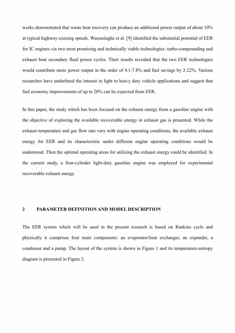
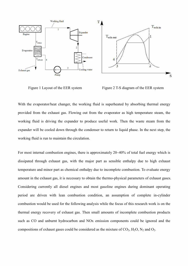
The EER system which will be used in the present research is based on Rankine cycle and
physically it comprises four main components: an evaporator/heat exchanger, an expander, a
condenser and a pump. The layout of the system is shown in Figure 1 and its temperature-entropy
diagram is presented in Figure 2.
Page 4
Figure 1 Layout of the EER system Figure 2 T-S diagram of the EER system
With the evaporator/heat changer, the working fluid is superheated by absorbing thermal energy
provided from the exhaust gas. Flowing out from the evaporator as high temperature steam, the
working fluid is driving the expander to produce useful work. Then the waste steam from the
expander will be cooled down through the condenser to return to liquid phase. In the next step, the
working fluid is run to maintain the circulation.
For most internal combustion engines, there is approximately 20~40% of total fuel energy which is
dissipated through exhaust gas, with the major part as sensible enthalpy due to high exhaust
temperature and minor part as chemical enthalpy due to incomplete combustion. To evaluate energy
amount in the exhaust gas, it is necessary to obtain the thermo-physical parameters of exhaust gases.
Considering currently all diesel engines and most gasoline engines during dominant operating
period are driven with lean combustion condition, an assumption of complete in-cylinder
combustion would be used for the following analysis while the focus of this research work is on the
thermal energy recovery of exhaust gas. Then small amounts of incomplete combustion products
such as CO and unburnt hydrocarbon and NOx emission components could be ignored and the
compositions of exhaust gases could be considered as the mixture of CO2, H2O, N2 and O2.
Page 5
Provided that the stoichiometric air-fuel ratio in the gasoline combustion is a0, and the actual one is
α, the molar fractions for N2 and O2 in the air mixture is kN2 and kO2, respectively. While the atom
numbers of carbon and hydrogen in the hydrocarbon fuel molecular are θC and θH, respectively, the
molar fractions of compositions in the exhaust gases could be obtained by the following equations,
respectively.
2/1 20
22
HO
NN
kaa
ak
θφ
−++=
2/1
(
20
2)0
2
HO
O
Okaa
kaa
θφ
−++
−=
2/1 20
2
HO
CCO
kaa θθ
φ−++
=
2/1
2/
20
2
HO
HOH
kaa θθ
φ−++
= (1)
Considering the above four compositions are all ideal gases, their constant pressure heat capacity
Cp,i could be achieved by the empirical formulas [10] :
RTcTcTcTccC ip )( 4
4
3
3
2
210, ++++= (2)
Given the exhaust gases ideal condition, the specific enthalpy could be calculated by:
∑ −×=i
iihMh 3
1 10ω (3)
where, ωi 、Mi and hi are the molar fraction、molar mass and specific enthalpy for each
composition. And the latter could be expressed by:
∫+=T
Tipi dTChh
0,0 (4)
Combined the equations (1) to (4), the specific enthalpy of exhaust gases can be achieved.
Page 6
It should be noted the above formulae can only be selected for calculating the specific enthalpy of
exhaust gases when all thermal recovery process did not involve steam condensation of exhaust gas
and there is only the sensible heat of the exhaust gases which is absorbed by the thermal recovery
system. When the steam condensing heat should be included if there is phase change of exhaust gas
via the evaporator, the exhaust specific enthalpy was obtained from NIST-Refprop database.
Then, the exhaust heat Qexh and its fraction in the total fuel energy could be given by:
exhoutexhexh mhhQ )( −= (5)
ff
exhexh
mh
Q=η
(6)
where, mexh and mf are the mass flow rate of exhaust gas and fuel, respectively, hexh and hf are the
corresponding exhaust gas enthalpies, and the low heating value of fuel.
For estimating the recoverable energy from exhaust sensible heat, the Chambadal-Novikov
efficiency or Curzon-Ahlborn efficiency [11] shown in the following formula is employed in the
current calculation.
inH
inL
pmT
T
,
,
, 1−=η (7)
where TL,in and TH,in represent the inlet temperatures of the cold and hot heat sinks with finite
thermal capacitance, i.e. the exhaust temperature at the heat exchanger exit Tout and the exhaust
temperature Texh,in for the calculation of the maximum convertible energy of exhaust.
The Chambadal-Novikov efficiency or Curzon-Ahlborn efficiency is for a semi-ideal engine
operating at maximum power output in which heat transfer is irreversible but other components are
ideal. It gives an upper bound on energy that can be derived from a real process that is lower than
Page 7
that predicted by Carnot for a Carnot cycle, and accommodates the exergy destruction occurring as
heat is transferred irreversibly [12].
Although sometime the Carnot efficiency is used to calculate the maximum recoverable energy, the
Chambadal-Novikov efficiency or Curzon-Ahlborn efficiency was proposed on the basis of
endoreversible cycle with the target of gaining the maximum output power which is the optimal
purpose for a EER system, becasure the latter one considered the temperature difference of heat
(cold) source and the working fluid which would cause irreversible loss. It is also thought the
Carnot efficiency would be equal to the Chambadal-Novikov efficiency or Curzon-Ahlborn when
the power outputs of a Carnot heat engine reach the maximum [12]. Klein checked this expression
and suggested that it gives a more realistic estimate of the efficiencies seen in real heat-power
cycles than the Carnot Approach [13].
By using the Chambadal-Novikov efficiency or Curzon-Ahlborn efficiency, the maximum energy
recovery from exhaust gases can be estimated as follows.
pmexhrexh QQ ,, η= (8)
Then, the exhaust recoverable energy efficiency based on the total fuel energy can be expressed as :
pmexhrexh ,, ηηη = (9)
The fraction of recoverable exhaust sensible heat in the total fuel energy is actually working as the
recoverable energy adaptive coefficient. The coefficient is proposed in the current study for
reflecting the fluctuations of exhaust temperature and recoverable exhaust energy with the engine
operating conditions, and also for estimating the available energy in the exhaust gas under all
mentioned engine operating conditions.
Page 8
After those above parameters were defined, simulations for estimating recoverable exhaust energy
with the above EER system and for finding the optimal operating conditions of the gasoline engine
to achieve the maximum power output were carried out on a MATLAB/SIMULINK platform. In the
simulation model, performance parameters for those critical components are considered as follow.
The Energy balance in the evaporator could be given as:
whe QQ =η (10)
Where, Qe and Qw represent the heat provided by the exhaust gas and the heat absorbed by the
working liquid, respectively. ηh is the efficiency of evaporator. This formula could be further
expressed by:
)()( ) inwoutwwhoutexhexh hhmhhm −− −=− η (11)
Where, mexh、hexh-in、hexh-out stand for the mass flow rate, inlet and outlet specific enthalpy for
exhaust gases respectively, and mw、hw-in、hw-out are the corresponding parameters for working
fluid.
The function of evaporator model is to simulate the heat transfer process in the evaporator by
calculating the outlet temperature of the working fluid at given pressure and flow rate. With the
assuming inlet parameters for the exhaust gases and working fluid and the sizes of the evaporator,
the outlet temperature could be yielded by iterative program. Basing on the design parameters of the
evaporator, the heat transferred in it could be also calculated as
mmw TAUQ ∆= (12)
Where, Um represents the average heat transfer coefficient of the heat transfer process, A is the
overall heat transfer area of evaporator, and ∆Tm is the logarithmic mean temperature difference in
Page 9
the heat transfer process.
For the expander, the specific enthalpy hw-out and entropy sexp in the inlet of expander could be
obtained with the results from the evaporator model. And the pressure pexp-out in the outlet of
expander would be determined by condensing pressure. Assuming the working fluid’s expansion
process is isentropic, the specific enthalpy in the outlet of expander could be identified by pexp-out
and sexp. Therefore, the power output produced by the expander could be calculated as
expexpexp )( ηoutwoutw hhmW −− −= (13)
Where, ηexp represents the expander efficiency.
In the pump, the process can be expressed with the following formula when the process is assumed
as isentropic.
pumpinpumpoutpumpwpump hhmW η)( −− −= (14)
3 TEST DESCRIPTION
As a close loop is still under construction, the present experiment is conducted on an open Rankine
cycle system which is connected with a 1.3-liter gasoline engine and the system structure is shown
in Figure 3. The main specifications of the engine is listed in Table 1. In the present test, water was
chosen as the working fluid.
Page 10
Figure 3 The open Rankine cycle system for exhaust energy recovery with a gasoline engine
Table 1 Specifications of CA4GA1 Engine
Engine type CA4GA1
Number of cylinders 4
Bore×Stroke (mm) 73×80
Displacement (L) 1.339
Compression ratio 10
Number of valves 16
Camshaft type DOHC
Rated power/speed
(kW/rpm) 67/6000
Maximum torque/speed
(Nm/rpm) 120/4200
4 RESULTS AND DISCUSSION
4.1 Distribution of Exhaust Gas Temperature
For studying EER, several parameters of air mass flow rate and exhaust gases, such as temperature,
mass flow rate, would be required for the calculation of exhaust energy. In those parameters, the
exhaust temperature plays a so important role, such as for the design of recovery system, the choice
of working fluids and the optimization of system [14]. Therefore, in order to make full advantages
Page 11
of exhaust energy, it is necessary to have adequate information of the distribution of exhaust gases
temperature under different engine operating conditions. As shown in Figure 4, it is the measured
exhaust gas temperature as function of engine speed and corrected engine load (torque).
It could be found that the exhaust gases temperature depends strongly on the engine speeds and
loads. Here it should be noted the actual vehicle operation normally needs the engine speed ranges
from 2000 to 4000 rpm. During the mid-range of the engine load (40-80 Nm), the corresponding
exhaust gases temperature of the test engine can be 500ºC to 700ºC, while it will be up to 850ºC at
the full load. It should be pointed out the data in Figure 1 were measured in the outlet of 3-way
catalyst, which is followed downstream by the heat exchanger of EER system. Therefore, based on
the exhaust temperate distribution, an appropriate evaporating temperature and mass flow rate
would be determined for the working fluids in the thermodynamic cycle of exhaust energy recovery.
Figure 4 Distribution of exhaust gases temperature of the test engine as function of engine speed
and torque
4.2 Model Validation and Process Parameters
The role of evaporator is so significant in the EER system because it directly dominates the
potential to recover the exhaust energy. Using the above model, the performance of evaporator was
Page 12
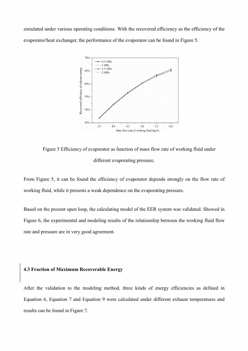
simulated under various operating conditions. With the recovered efficiency as the efficiency of the
evaporator/heat exchanger, the performance of the evaporator can be found in Figure 5.
Figure 5 Efficiency of evaporator as function of mass flow rate of working fluid under
different evaporating pressure.
From Figure 5, it can be found the efficiency of evaporator depends strongly on the flow rate of
working fluid, while it presents a weak dependence on the evaporating pressure.
Based on the present open loop, the calculating model of the EER system was validated. Showed in
Figure 6, the experimental and modeling results of the relationship between the working fluid flow
rate and pressure are in very good agreement.
4.3 Fraction of Maximum Recoverable Energy
After the validation to the modeling method, three kinds of energy efficiencies as defined in
Equation 6, Equation 7 and Equation 9 were calculated under different exhaust temperatures and
results can be found in Figure 7.
Page 13
Figure 6 Comparison of experimental and modeling results regarding working fluid mass flow
rate under different evaporating pressure (δT - over-heat degree)
Figure 7 Variation of ηm,p, ηexh, and ηexh,r as function of the exhaust gases temperature
It could be seen that all three efficiencies present nearly linearity with the exhaust gases temperature.
And the fraction of maximum recoverable energy in the total fuel energy ηexh,r could exceed 20%
when the temperature is over 800℃. The temperature characteristics, combined with the distribution
Page 14
of exhaust gases temperature, could infer further the optimal conditions that would benefit most to
the EER system.
In the real drive cycle of vehicle, the engine speed can range around 2000 rpm to 4000 rpm for most
driving conditions. Here, three typical speeds were chosen to demonstrated the variations of the
exhaust recoverable efficiency ηexh,r with different engine speeds, as presented in Figure 8.
Figure 8 Variations of recoverable exhaust energy efficiency ηexh,r with different operating
conditions of the test engine
In Figure 8, it could be seen that, given a certain speed, ηexh,r increases firstly as the load increases,
and reaches up to a maximum when the torques increase among 90 Nm and 100 Nm. Then it will
decrease if the torques continues to increase further. There exists an optimal operating condition for
each engine speed to produce the maximum recoverable exhaust energy. Comparison among the
cases in different speeds could make clear that the higher the engine speed, the larger ηexh,r will be
possible. This could be explained by the fact that the increase of speed would give rise to the
increase of the exhaust gases temperature.
Basing on the distribution of the exhaust gases temperature with the engine speeds and loads as
shown in Figure 4, the distribution of ηexh,r as function of operating conditions could be achieved in
Page 15
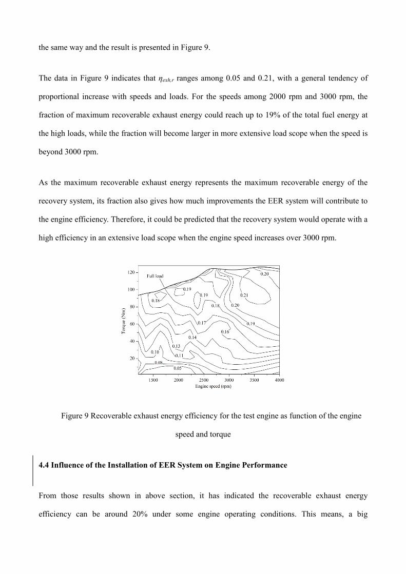
the same way and the result is presented in Figure 9.
The data in Figure 9 indicates that ηexh,r ranges among 0.05 and 0.21, with a general tendency of
proportional increase with speeds and loads. For the speeds among 2000 rpm and 3000 rpm, the
fraction of maximum recoverable exhaust energy could reach up to 19% of the total fuel energy at
the high loads, while the fraction will become larger in more extensive load scope when the speed is
beyond 3000 rpm.
As the maximum recoverable exhaust energy represents the maximum recoverable energy of the
recovery system, its fraction also gives how much improvements the EER system will contribute to
the engine efficiency. Therefore, it could be predicted that the recovery system would operate with a
high efficiency in an extensive load scope when the engine speed increases over 3000 rpm.
Figure 9 Recoverable exhaust energy efficiency for the test engine as function of the engine
speed and torque
4.4 Influence of the Installation of EER System on Engine Performance
From those results shown in above section, it has indicated the recoverable exhaust energy
efficiency can be around 20% under some engine operating conditions. This means, a big
Page 16
improvement on the engine efficiency can be achieved with EER system. While the above results
were produced with the assumption that the EER system would not give any side effect of the
exhaust gas flow, it is necessary to find if this is true or not.
(a)
(b)
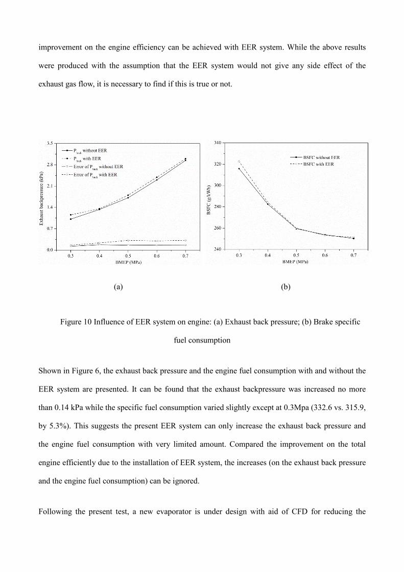
Figure 10 Influence of EER system on engine: (a) Exhaust back pressure; (b) Brake specific
fuel consumption
Shown in Figure 6, the exhaust back pressure and the engine fuel consumption with and without the
EER system are presented. It can be found that the exhaust backpressure was increased no more
than 0.14 kPa while the specific fuel consumption varied slightly except at 0.3Mpa (332.6 vs. 315.9,
by 5.3%). This suggests the present EER system can only increase the exhaust back pressure and
the engine fuel consumption with very limited amount. Compared the improvement on the total
engine efficiently due to the installation of EER system, the increases (on the exhaust back pressure
and the engine fuel consumption) can be ignored.
Following the present test, a new evaporator is under design with aid of CFD for reducing the
Page 17
exhaust gas flow resistance further. It is expected the new design will be possible to make the
increase of exhaust back pressure very close zero.
5 CONCLUSIONS
In the current study, experiments were performed on a light duty gasoline engine for obtaining
thermodynamic parameters of exhaust gases under different operating conditions. Based on the
experimental data, the exhaust heat and maximum recoverable exhaust energy for an EER (Exhaust
Energy Recovery) system based on Rankine Cycle were calculated and analyzed, including the
characteristics in terms of temperature and other operating conditions. From those results, the
following conclusions can be derived:
• A new parameter, the recoverable exhaust energy efficiency which is actually the fraction of
maximum recoverable exhaust energy in the total fuel energy is recommended for reflecting the
effects of exhaust temperature and possible exhaust heat on EER efficiency under different
engine operating conditions.
• The exhaust gases temperature increases with both of the speed and load in the overall operating
conditions of vehicle, ranging among 400ºC and 850ºC for the tested light duty gasoline engine.
Experimental results of relevant parameters would be beneficial to determining the appropriate
evaporating temperature and mass flow rate for the working fluids in the thermodynamic cycle
of EER.
• For the EER system installed on the light duty gasoline engine with water as the working fluid,
the recoverable exhaust energy efficiency ranges among 5% and 21% under different engine
operating condition. It tends to increase with engine speed and load. When the speed is beyond
3000 rpm, the coefficient could be up to 19% in a rather wide load range.
Page 18
ACKNOWLEDGEMENTS
Financial supports from the National Basic Research Program of China (973 Program) through the
project of 2011CB707201 and the National Natural Science Found of China (NSFC) through
the project of 50876074 are gratefully acknowledged.
REFERENCES
1. Taylor A.M.K.P, Science review of internal combustion engines, Energy Policy. 36 (2008)
4657-4667.
2. Vazaquez J, Zanz-BobiMA, Palacios R, Arenas A. State of the art of thermoelectric
generators based on heat recovered from the exhaust gases of automobiles. Proceedings of
7th European workshop on thermoelectrics, 2002.
3. El Chammas, R.G. and D. Clodic, Combined Cycle for Hybrid Vehicles. SAE 2005 World
Congress & Exhibition, 2005. SP-1973 (2005-01-1171).
4. Tianyou Wang, Yajun Zhang, Zhijun Peng, Gequn Shu. A review of researches on thermal
exhaust heat recovery with Rankine cycle. Renewable and Sustainable Energy Reviews
(2011) 2862-2871.
5. Teng H, Regner G, Cowland C. Achieving high engine efficiency for heavy-duty diesel
engines by waste heat recovery using supercritical organic-fluid Rankine cycle. SAE paper
2006-01-3522, 2006
6. Teng H, Regner G, Cowland C. Waste heat recovery of heavy-duty diesel engines by organic
Rankine cycle Part I: hybrid energy system of diesel and Rankine engines. SAE paper 2007-
Page 19
01-0537, 2007.
7. Teng H, Regner G. Improving fuel economy for HD diesel engines with EHR Rankine cycle
driven by EGR cooler heat rejection. SAE paper 2009-01-2913, 2009.
8. Ringler J, Seifert M, Guyotot V, Hübner W. Rankine cycle for waste heat recovery 697 of
IC engines. SAE paper 2009-01-0174, 2009.
9. Weerasinghe WMSR, Stobart RK, Hounsham SM. Thermal efficiency improvement in high
output diesel engines a comparison of a Rankine cycle with turbo-compounding. Appl
Therm Eng 2010,30:2253-6.
10. W.D. Shen, Z.M. Jiang, J.G. Tong, Engineering Thermodynamics, third ed., Higher
Education Press, Beijing, 2001.
11. O.M. Ibrahim, S.A. Klein, J.W. Mitchell, Optimum heat power cycles for specified
boundary conditions, ASME Journal of Engineering for Gas Turbines and Power. 113 (1991)
514-521.
12. Jincan Chen, Zijun Yan, Guoxing Lin, Bjarne Andresen, On the Curzon-Ahlborn efficiency
and is connection with the efficiency of real heat engines. Energy Conversion &
Management 42 (2001) 173±181.
13. S.A. Klein, An explanation for observed compression ratios in internal combustion engines,
ASME Journal of Engineering for Gas Turbines and Power. 113 (1990) 511-513.
14. J. Ringler, M. Seifert, V. Guyotot, W. Hübner, Rankine cycle for waste heat recovery of IC
engines, SAE paper 2009-01-0174.