171 QR of RTRI, Vol. 55, No. 3, Aug. 2014 Masakazu TAKAGAKI Hirotaka SAKAI Analysis of Rolling Contact Behavior between Wheel and Rail through Large-scale Parallel Computing Masae HAYASHI Computational Mechanics Laboratory, Railway Dynamics Division Akira AIKAWA Track Dynamics Laboratory, Railway Dynamics Division This paper attempts to analyze dynamic wheel/rail rolling contact through application of a three-dimensional finite element method with large-scale parallel computing. This analy- sis clarifies the dynamic behavior of the contact patch, when a wheel rolls on a rail at a high speed with loading torque. A rail model which allows efficient calculation was developed to accelerate a wheel on a small size rail model. In addition, this method employs dynamic mesh partitioning to maintain meshes in the contact patch in one partition region during the wheel rolling for efficient parallel calculation. Using this method has made it possible to evaluate the dynamic wheel/rail rolling contact behavior. Keywords: dynamic rolling contact, finite element method, large-scale parallel computing, dynamic partitioning 1. Introduction Impact loads exerted on the wheel/rail interface with passing trains not only cause wear and wheel or rail frac- tures, they also lead to track deterioration through vibra- tion propagated from the wheel/rail interface to the sleeper or underlying ballast layer. And yet insight still remains to be gathered regarding the damage generating mechanisms, such as wheel flats, rail corrugation, ballast abrasion and so on. Being able to evaluate the impact load on the wheel/ rail interface can therefore provide the information re- quired to clarify these mechanisms, which in turn can help develop effective countermeasures. The actual wheel/rail contact area (contact patch) is very small - only 10-20 mm in size. As a result, the mesh size used has to be very small in order to accurately assess stress distribution in the con- tact patch. Furthermore, it is not only necessary to model one wheel, but several wheels/bogies/car sets in order to clarify the type of track deterioration coming into play. Consequently, a dynamic contact analysis method to ex- amine the wheel/rail interface through three-dimensional finite element method with large-scale parallel computing was developed. Many different approaches have been developed to study the wheel/rail contact interface issues. For example, numerical analysis of the problem has been conducted to take certain aspects into consideration, such as sliding, rotation, surface roughness of rail, wear progress, inter alia [1-5]. However, in almost all the previous approaches, only one region of the contact patch was modeled in detail, and contact analysis calculations and rolling simulations were carried out separately. Further, the wheel rolling was modeled as not a torque but an enforced displacement, in these simulations. None of these methods however express the actual dynamic behavior at the wheel/rail interface. In addition, the waveforms of the impact load contain high frequency components. The impact load including the high frequency components therefore need to be simulated to evaluate the contact patch appropriately. This paper de- scribes the customization of the “FrontISTR”[6], three- dimensional finite element analysis program with large- scale parallel computing to deal with the wheel/rail contact problem. 2. Description of the numerical analysis 2.1 Simulation method for rolling contact problem The track model is divided into two sections. One sec- tion is ‘the run-up section’ in which the wheel is acceler- ated from zero to the required speed, and the other is ‘the evaluation section’ over which the contact patch is evalu- ated in detail, with due consideration of the influence from surface irregularity and so on. In this study, modifications were made to the finite element analysis program ‘Fron- tISTR’ for the purposes of investigating wheel/rail contact problems. The original program ‘FrontISTR’was devel- oped by Professor Okuda, of the University of Tokyo. 2.1.1 Development of a ‘Caterpillar Mesh’, and im- provement in efficiency of calculation The size of the contact patch is very small in compari- son to the wheel or the rail size. Therefore, when conduct- ing rolling contact analysis, the length of the rail which has dynamic influence on a contact part is short. It means that in the run-up section, a part of the rail model which is fully away from a wheel after the wheel passage becomes unnecessary. Therefore, the rail model in the run-up sec- tion is divided into two or more same length blocks as shown in Fig.1. When the wheel rolls over one block length distance, the back-end block whose influence on the contact domain can be ignored is transposed to the front-end. Since the behaviour of this rail model is similar to a caterpillar, it was named the ‘Caterpillar Mesh’. This feature makes PAPER
Transcript
171QR of RTRI, Vol. 55, No. 3, Aug. 2014
Masakazu TAKAGAKIHirotaka SAKAI
Analysis of Rolling Contact Behavior between Wheel and Rail through Large-scale Parallel Computing
This paper attempts to analyze dynamic wheel/rail rolling contact through application of a three-dimensional finite element method with large-scale parallel computing. This analy-sis clarifies the dynamic behavior of the contact patch, when a wheel rolls on a rail at a high speed with loading torque. A rail model which allows efficient calculation was developed to accelerate a wheel on a small size rail model. In addition, this method employs dynamic mesh partitioning to maintain meshes in the contact patch in one partition region during the wheel rolling for efficient parallel calculation. Using this method has made it possible to evaluate the dynamic wheel/rail rolling contact behavior.
Keywords: dynamic rolling contact, finite element method, large-scale parallel computing, dynamic partitioning
1. Introduction
Impact loads exerted on the wheel/rail interface with passing trains not only cause wear and wheel or rail frac-tures, they also lead to track deterioration through vibra-tion propagated from the wheel/rail interface to the sleeper or underlying ballast layer. And yet insight still remains to be gathered regarding the damage generating mechanisms, such as wheel flats, rail corrugation, ballast abrasion and so on. Being able to evaluate the impact load on the wheel/rail interface can therefore provide the information re-quired to clarify these mechanisms, which in turn can help develop effective countermeasures. The actual wheel/rail contact area (contact patch) is very small - only 10-20 mm in size. As a result, the mesh size used has to be very small in order to accurately assess stress distribution in the con-tact patch. Furthermore, it is not only necessary to model one wheel, but several wheels/bogies/car sets in order to clarify the type of track deterioration coming into play. Consequently, a dynamic contact analysis method to ex-amine the wheel/rail interface through three-dimensional finite element method with large-scale parallel computing was developed.
Many different approaches have been developed to study the wheel/rail contact interface issues. For example, numerical analysis of the problem has been conducted to take certain aspects into consideration, such as sliding, rotation, surface roughness of rail, wear progress, inter alia [1-5]. However, in almost all the previous approaches, only one region of the contact patch was modeled in detail, and contact analysis calculations and rolling simulations were carried out separately. Further, the wheel rolling was modeled as not a torque but an enforced displacement, in these simulations. None of these methods however express the actual dynamic behavior at the wheel/rail interface. In addition, the waveforms of the impact load contain high frequency components. The impact load including the high frequency components therefore need to be simulated to
evaluate the contact patch appropriately. This paper de-scribes the customization of the “FrontISTR” [6], three-dimensional finite element analysis program with large-scale parallel computing to deal with the wheel/rail contact problem.
2. Description of the numerical analysis
2.1 Simulation method for rolling contact problem
The track model is divided into two sections. One sec-tion is ‘the run-up section’ in which the wheel is acceler-ated from zero to the required speed, and the other is ‘the evaluation section’ over which the contact patch is evalu-ated in detail, with due consideration of the influence from surface irregularity and so on. In this study, modifications were made to the finite element analysis program ‘Fron-tISTR’ for the purposes of investigating wheel/rail contact problems. The original program ‘FrontISTR’ was devel-oped by Professor Okuda, of the University of Tokyo.
2.1.1 Development of a ‘Caterpillar Mesh’, and im-provement in efficiency of calculation
The size of the contact patch is very small in compari-son to the wheel or the rail size. Therefore, when conduct-ing rolling contact analysis, the length of the rail which has dynamic influence on a contact part is short. It means that in the run-up section, a part of the rail model which is fully away from a wheel after the wheel passage becomes unnecessary. Therefore, the rail model in the run-up sec-tion is divided into two or more same length blocks as shown in Fig.1. When the wheel rolls over one block length distance, the back-end block whose influence on the contact domain can be ignored is transposed to the front-end. Since the behaviour of this rail model is similar to a caterpillar, it was named the ‘Caterpillar Mesh’. This feature makes
PAPER
172 QR of RTRI, Vol. 55, No. 3, Aug. 2014
possible to evaluate the wheel passage continuously, reduc-ing the whole model size. In this paper, all the results are evaluated in the run-up section for the verification of the program.
2.1.2 Removal of influence of the elastic wave by in-troduction of a non-reflecting boundary
When the high-frequency vibration is evaluated up to 2 kHz in the analysis, the elastic wave reflected at both the ends of the rail model adversely affects the evaluation of a contact patch. Then, an appropriate result conceivably cannot be obtained in a high frequency band. As a conse-quence, the artificial Rayleigh damping ‘non-reflecting boundary’ is applied to one or some rail model blocks adja-cent to both ends of the rail model, to attenuate the elastic wave (Fig. 2).
Fig. 1 Description of ‘Caterpillar Mesh’
Fig. 2 Description of the non-reflecting boundary
Impact load
Propag
ation
(Impu
lse wav
e)
Non-re
flecti
ng
boun
dary
Dampin
g
2.1.3 Accelerating simulation performance
As mentioned above, the contact area between wheel/rail is small compared with the size of the wheel or the rail. Since the purpose of this research is evaluation of con-tact behaviour, the mesh size of the contact domain should be sufficiently small (at least 1 mm × 1 mm), making the whole calculation volume huge. Therefore, parallel comput-ing for finite element analysis is indispensable. Moreover, if an iterative method is used for a simultaneous-equation solution (solver) to perform contact calculations, conver-
Wheel
Rail
Same domain Re-partitioning by on-memory sequence(without I/O) to calculate in the same domain both wheel and rail all the time
Contact area
Rolling
Next domain in the wheel contacts the rail in the contact patch(Occurrence of the data communication between two domains)
Re-partitioning
gence of the solution will be remarkably slow or it will not be completed at all in many cases. Hence, the direct meth-od solver MUMPS [7] for distributed memory type parallel computing is introduced for this calculation with the large-scale model. Additionally, in this program, when perform-ing contact calculation of the wheel/rail, in order to avoid the data communication between two or more memory domains, as shown in Fig. 3, data in the parts of the wheel and the rail near the contact patch are stored in the same domain. As the wheel rolls, the contact area covers the two domains. Then, dynamic re-partitioning is carried out so that the calculation is executed for the same domain all the time. In addition, in order to process domain decomposition at high speed, dynamic re-partitioning is carried out by on-memory sequence (without I/O).
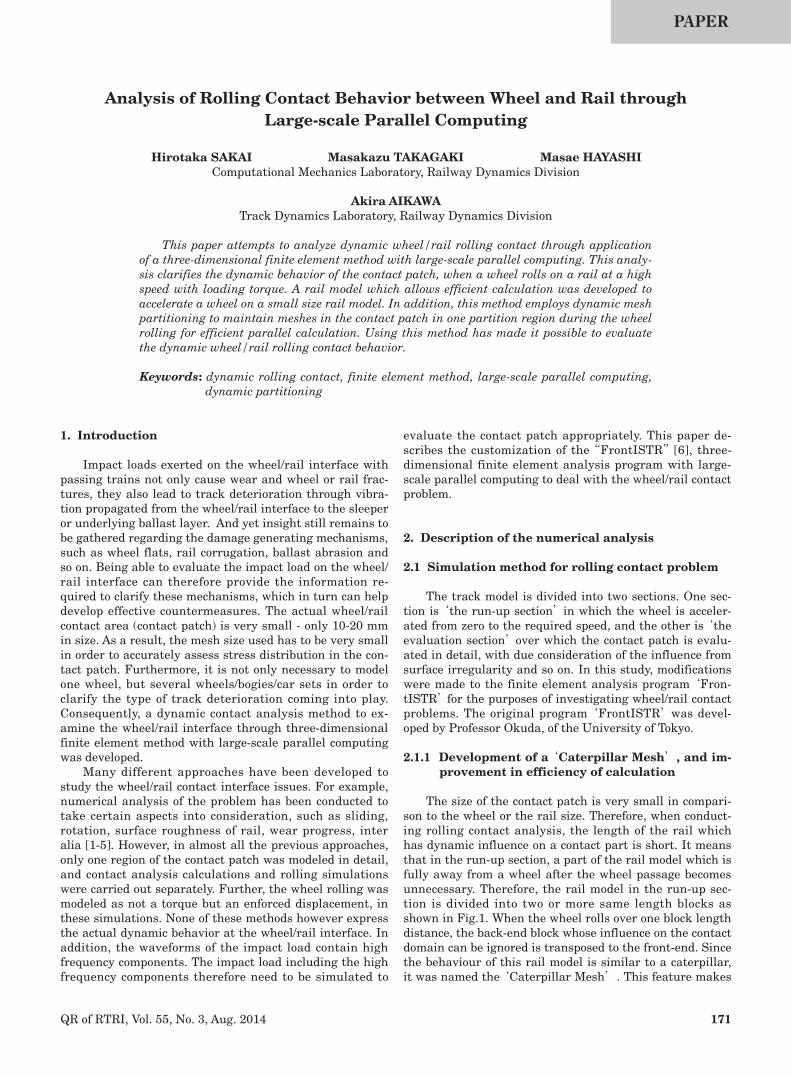
2.2 Analysis models
The specifications set for the material properties of the wheel and the rail were the same as those of steel wheel-sets on Shinkansen vehicles and the steel 60 kg rails. Here, both the wheel/rail were calculated as an elastic body for the verification of the program. All meshes consist of an 8-node hexahedral element. In order to gain insight into the contact patch behavior in trial calculations, a simple model of a disk and rail was constructed (A1). It is possible to examine the stability of calculation during high speed rolling. Another model A2, which has fine mesh size only around the contact part between wheel/rail of A1, is used to evaluate the contact patch behaviour efficiently. Further, a real shape model (B) was prepared to make a comparison with the measurement results of the full-scale experiment or those of a commercial line. Figures 4(a)-4(c) show the description of the models A1, A2, and B. The number of nodes, elements, and contact part mesh size in each model are shown in Table 1. In all these models, a one axle/one wheel model with one wheel and a half of axle on one side rail was adopted. An axle load of 50 kN was given as a concentrated load at the journal end of the axle, and con-centrated loads equivalent to the torque acting in tangent direction on the axle was added on the surface of the axle. As a boundary condition, the node of the symmetry plane of the axle was restrained in the longitudinal direction, and the node of the rail bottom was restrained completely. To solve the rolling contact problem, the axle load was added, first. After the contact state stabilised, a concentrated load equivalent to the torque was applied.
Fig. 3 Description of the domain decomposition
173QR of RTRI, Vol. 55, No. 3, Aug. 2014
Fig. 4(a) Description of model A1
Fig. 4(b) Description of model A2
Fig. 4(c) Description of model B
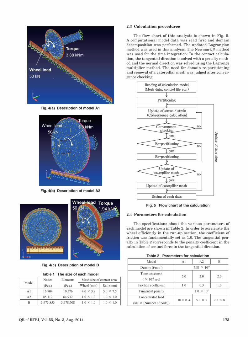
2.3 Calculation proceduree
The flow chart of this analysis is shown in Fig. 5. A computational model data was read first and domain decomposition was performed. The updated Lagrangian method was used in this analysis. The Newmark b method was used for the time integration. In the contact calcula-tion, the tangential direction is solved with a penalty meth-od and the normal direction was solved using the Lagrange multiplier method. The need for domain re-partitioning and renewal of a caterpillar mesh was judged after conver-gence checking.
The specifications about the various parameters of each model are shown in Table 2. In order to accelerate the wheel efficiently in the run-up section, the coefficient of friction was fundamentally set as 1.0. The tangential pen-alty in Table 2 corresponds to the penalty coefficient in the calculation of contact force in the tangential direction.
Torque3.88 kNm
Wheel load50 kN
Torque5.6 kNm Wheel load
50 kN
Table 2 Parameters for calculationModel A1 A2 B
Density (t/mm3) 7.81 × 10⁻⁹
Time increment
( × 10-4 sec)5.0 2.0 2.0
Friction coefficient 1.0 0.3 1.0
Tangential penalty 1.0 × 10⁴
Concentrated load
(kN × [Number of node])10.0 × 4 5.0 × 8 2.5 × 8
Reading of calculation model(Mesh data, control file etc.)
Partitioning
Update of stress / strain(Convergence calculation)
Convergence checking
yes
Re-partitioning
Re-partitioning
Update of caterpillar mesh
Update of caterpillar mesh
Saving of each data
no
yes
yes
no
no
Update o
f time step
174 QR of RTRI, Vol. 55, No. 3, Aug. 2014
3. Results and Discussions
3.1 The trial calculation results by the simple model A1
Figure 6 shows the time history of the translational speed of the wheel (wheel speed) in the longitudinal direc-tion of the rail, and the displacement at the center of end face of the wheel axle. In addition the vertical direction displacement at the center of end face of the wheel axle is shown in Fig. 7.
Figure 6 shows that the wheel speed reaches approxi-mately 270 km/h in 4.8 seconds because we apply the larg-er torque in this analysis than that in the actual vehicle. Figure 7 shows that the analysis was conducted stably even in the high speed region. Here, the vertical displace-ment reached 0.2 mm in the early stages of this analysis because there was some space between the wheel and the rail in the initial state of an analysis model. Focusing on the vibration in detail in Fig. 7, two components can be observed: one consisting mainly of high frequency compo-nents does not depend on time, and the other consisting of low frequency components whose dominant frequency becomes higher with increasing wheel speed. The former component is considered to be artificial vibration due to the numerical integral and the latter is vibration according to the rolling speed of the wheel.
Fig. 7 Vertical displacement of the wheel axle
Fig. 6 Wheel speed and longitudinal displacement of the wheel
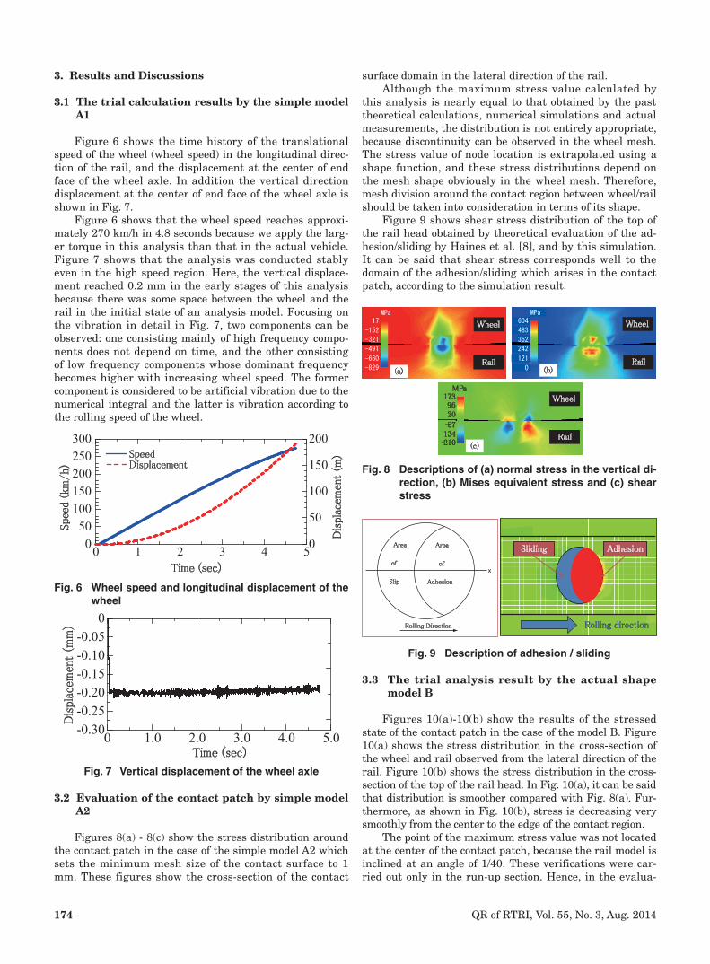
3.2 Evaluation of the contact patch by simple model A2
Figures 8(a) - 8(c) show the stress distribution around the contact patch in the case of the simple model A2 which sets the minimum mesh size of the contact surface to 1 mm. These figures show the cross-section of the contact
Fig. 8 Descriptions of (a) normal stress in the vertical di-rection, (b) Mises equivalent stress and (c) shear stress
Wheel
Rail(a) (b)
Rail
MPa1739620
-57-134-210
Wheel
Rail(c)
Wheel
MPa17
-152
-321
-491
-660
-829
MPa604
483
362
242
121
0
3.3 The trial analysis result by the actual shape model B
Figures 10(a)-10(b) show the results of the stressed state of the contact patch in the case of the model B. Figure 10(a) shows the stress distribution in the cross-section of the wheel and rail observed from the lateral direction of the rail. Figure 10(b) shows the stress distribution in the cross-section of the top of the rail head. In Fig. 10(a), it can be said that distribution is smoother compared with Fig. 8(a). Fur-thermore, as shown in Fig. 10(b), stress is decreasing very smoothly from the center to the edge of the contact region.
The point of the maximum stress value was not located at the center of the contact patch, because the rail model is inclined at an angle of 1/40. These verifications were car-ried out only in the run-up section. Hence, in the evalua-
Fig. 9 Description of adhesion / sliding
x
Rolling Direction
Area Area
of of
Slip Adhesion
Rolling direction
AdhesionSliding
surface domain in the lateral direction of the rail.Although the maximum stress value calculated by
this analysis is nearly equal to that obtained by the past theoretical calculations, numerical simulations and actual measurements, the distribution is not entirely appropriate, because discontinuity can be observed in the wheel mesh. The stress value of node location is extrapolated using a shape function, and these stress distributions depend on the mesh shape obviously in the wheel mesh. Therefore, mesh division around the contact region between wheel/rail should be taken into consideration in terms of its shape.
Figure 9 shows shear stress distribution of the top of the rail head obtained by theoretical evaluation of the ad-hesion/sliding by Haines et al. [8], and by this simulation. It can be said that shear stress corresponds well to the domain of the adhesion/sliding which arises in the contact patch, according to the simulation result.
175QR of RTRI, Vol. 55, No. 3, Aug. 2014
Fig. 10 Descriptions of (a) normal stress of vertical di-rection of wheel/rail and (b) Mises equivalent stress of rail head
(b)
Rail
10 mm
MPa
(a)
Wheel
Rail
7
-173
-352
-531
-710
-889
MPa
655
524
393
262
131
0
tion section, we will verify our calculation results, such as evaluation of contact patch behavior during rolling of the wheel, evaluation of impact load at the contact patch pro-vided with irregularities such as corrugation, welding joint and so on, by comparing them with the past experiments and actual measurements.
4. Conclusions
In the present paper, the analysis technique of dynamic contact between the wheel/rail using the three-dimensional finite element method was developed. To evaluate the im-pact load which arises between the wheel/rail by a large-scale model, finite element analysis program ‘FrontISTR’ was customized. This program includes some originalities: the adoption of the ‘Caterpillar Mesh’ to reduce the whole mesh number in the run-up section, the introduction of a non-reflecting boundary to keep the accuracy of the dy-namic behavior in the contact patch in the high frequency range, and the development of re-partitioning by on-memory to pack contact area between wheel and rail in one domain all the time. As a result, it was confirmed that this technique can reproduce the impact load, hold down the calculation cost, and perform the stable analysis even in the high-speed region. In the future, a rail model provided with rail irregularity such as corrugation will be construct-ed in the evaluation section after accelerating the wheel to the required speed in the run-up section. Then, another model with elements which have the same elasticity as that of a sleeper pad at the rail bottom for every sleeper
will be constructed and used for studying the mechanism of dynamic contact between the wheel and the rail.
Acknowledgment
This customized program has been developed with the collaboration of Prof. Okuda, of the Univ. of Tokyo, and Ad-vanced Simulation Technology of Mechanics Co., Ltd. The authors would like to express their sincere gratitude to them.
References
[1] Kalker, J. J., Three-Dimensional Elastic Bodies in Rolling Contact, Kluwer Academic Publishers, 1990.
[2] Piotrowski, J. and Kik, W., “A simplified model of wheel/rail contact mechanics for non-Hertzian prob-lems and its application in rail vehicle dynamic simu-lations,” Vehicle System Dynamics, Vol. 46, No. 1, pp. 27-48, 2008.
[3] Baeza, L., Vila, P. et al., “Prediction of rail corrugation using a rotating flexible wheelset coupled with a flex-ible track model and a non-Hertzian / non-steady con-tact model,” Journal of Sound and Vibration, Vol. 330, pp. 4493-4507, 2011.
[4] Pletz, M., Daves, W. et al., “Multi-Scale Finite Element Model to Describe Wear and Rolling Contact Fatigue in the Wheel-Rail Test Rig,” presented at the 9th Inter-national Conference on Contact Mechanics and Wear of Rail/Wheel Systems, Aug. 27-30, 2012.
[5] Zhao, X. and Li, Z., “The solution of frictional wheel-rail rolling contact with a 3D transient finite element model: Validation and error analysis,” Wear, Vol. 271, pp. 444-452, 2011.
[6] Okuda, H., “Structural Analysis for Large Scale As-sembly: Research and Development of Innovative Simulation Software,” http://www.ciss.iis.u-tokyo.ac.jp/riss/english/project/structure/
[7] “MUMPS: A Parallel Sparse Direct Solver,” http://graal.ens-lyon.fr/MUMPS/
[8] Haines, D. J. and Ollerton, E., “Contact Stress Dis-tributions on Elliptical Contact Surfaces subjected to Radial and Tangential Forces,” presented at the Insti-tution of Mechanical Engineers, 1963, Vol. 177, pp. 95-114.