Page 1/9 Analysis of prevalent scrap yard layouts finding the optimum level of efficiency, flexibility and operational cost Authors: Stephanie Feger – Consultant Human Resources – Badische Stahl-Engineering GmbH, Kehl / Germany Klaus Zehnle – Senior Consultant Logistic – Badische Stahl-Engineering GmbH, Kehl / Germany Figure 1: Scrap yard at BSW / Germany Introduction In these days, lots of attention is paid to the raw material costs, representing the largest single cost factor (>50 %) in mini-mill operations. Especially when taking into consideration a global economic environment surrounded by uncertainties and risks, e.g. structural imbalances in the European Union as well as a high volatility regarding raw material and steel prices, taking care about which types of scrap to use, finding possibilities for substitution of expensive raw material sources and the usage of standardised charging recipes become increasingly evident. However, raw material costs not only include the raw material costs themselves, but also often neglected but equally important costs for scrap purchasing and inventory management as well as for scrap yard logistics and operations, i.e. material storage and material handling.
Transcript
Page 1/9
Analysis of prevalent scrap yard layouts finding the optimum level of efficiency, flexibility and operational cost
Authors:
Stephanie Feger – Consultant Human Resources – Badische Stahl-Engineering GmbH,
In these days, lots of attention is paid to the raw material costs, representing the largest
single cost factor (>50 %) in mini-mill operations.
Especially when taking into consideration a global economic environment surrounded
by uncertainties and risks, e.g. structural imbalances in the European Union as well as
a high volatility regarding raw material and steel prices, taking care about which types
of scrap to use, finding possibilities for substitution of expensive raw material sources
and the usage of standardised charging recipes become increasingly evident.
However, raw material costs not only include the raw material costs themselves, but
also often neglected but equally important costs for scrap purchasing and inventory
management as well as for scrap yard logistics and operations, i.e. material storage
and material handling.
Page 2/9
Without any doubt, the scrap storage policy and the material flow have a major impact
on production figures and operation costs, for example double handling of scrap and
up- and downstream waiting times.
As a result, a steelmaker’s overall success is critically dependent on the efficiency of its
scrap purchasing strategy, scrap yard logistics and operations. Ideally, a scrap yard
should be customised and tailor-made as to the requirements of the plant.
Various Criteria for design and operation of a scrap storage facility
Figure 2: Criteria for design and operation
The way a mini-mill‘s scrap yard is designed, organised and operated depends on lots
of different criteria such as:
Way of scrap supply, i.e. railway, truck, barge
Steel quality produced, e.g. number and amount of different scrap types
Plant capacity as well as planned annual output
Available space strongly influencing scrap handling and storage design
Plant design and material flow, e.g. way of bucket transfer to melt shop and
number of EAFs
Raw material purchasing strategy and availability on the market
Environmental issues and governmental regulations, e.g. noise limitations and
radioactivity measuring regulations
Page 3/9
As a result, almost every scrap storage facility around the world is unique. This proofs
also a statistical evaluation of 100 scrap storage facilities around the world conducted
by BSE in February 2013. In the statistical evaluation the following topics have been
covered amongst others:
Means of transport used for scrap supply
Storage facility
Type of bucket loading crane
Scrap bucket transfer
Figure 3: Statistical evaluation of scrap storage facilities world wide
Regarding the means of transport used for scrap supply, a big change in comparison to
earlier times becomes evident. Whereas in earlier times scrap was predominantly
supplied by railroad, the situation has changed drastically. Today, trucks are the most
preferred means of transportation, followed by railroad on second place and barge on
third place. (Remark: Lots of plants dispose of a combination of different means of
transportation leading to the possibility of multiple nominations.) However, 61 % are
using trucks for scrap supply, thereof 48 % exclusively, i.e. by 100 %. 30 % are using
railroad, thereof only one plant as exclusive means of transportation, the others only in
combination with other means of transportation. 9 % are using barges, but in BSE’s
sample size, there is no plant which uses barges for 100 %, i.e. barges are always used
in combination with other means of transportation.
Page 4/9
As to the storage facility for bucket loading, 76 % are using scrap bays, thereof 50 %
are equipped with a roof. 21 % of the plants are equipped with a scrap yard and 3 %
dispose of a combination of both for loading of the scrap bucket. In addition to the
internal scrap storage facilities, 21 % have an additional external scrap yard actively
used in order to supply the internal scrap storage facility limited in capacity. Another
22 % dispose of an external yard they mainly use as a strategic one, i.e. not for bucket
loading, but for buffer in times of high raw material prices, limited availability of special
raw material types, etc.
For the analysis of the type of the bucket loading crane used, multiple nominations have
been possible, because some plants have a combination of overhead and mobile
cranes. 74 % of the plants have overhead cranes in place, thereof 6 % are using both,
overhead and mobile cranes at the same time. Another 15 % are equipped with mobile
cranes, followed by 7 % with gantry cranes, 3 % of plants are equipped with a balance
crane and only 1 % of all plants of the sample uses other vehicles like e.g. cater pillars
and thus no cranes at all.
As to the scrap bucket transfer between storage facility and melt shop, 75 % of the
plants do it by rail, 16 % by road and 9 % without any moving scrap car. In this case,
the transportation of the scrap bucket is directly done by charging crane, i.e. the scrap
bucket is fixed at a certain place of the melting bay, charged by a truck (which gets of
course charged before by a crane) and afterwards moved to the EAF by the charging
crane. Thus no transfer on road or rail via scrap car is necessary. However, the regional
distribution may look very different. Whereas in the US lots of plants are doing their
bucket loading without any moving scrap car, in other parts of the world this way of
bucket loading is very seldom.
Of course, the layout of each and every steel plant around the world is influenced by the
side conditions stated before. However, one outcome of the statistical evaluation is that
most of the scrap storage facilities can be grouped into one of the three “typical” layouts
described in the following.
Internal scrap bay with fixed scrap car
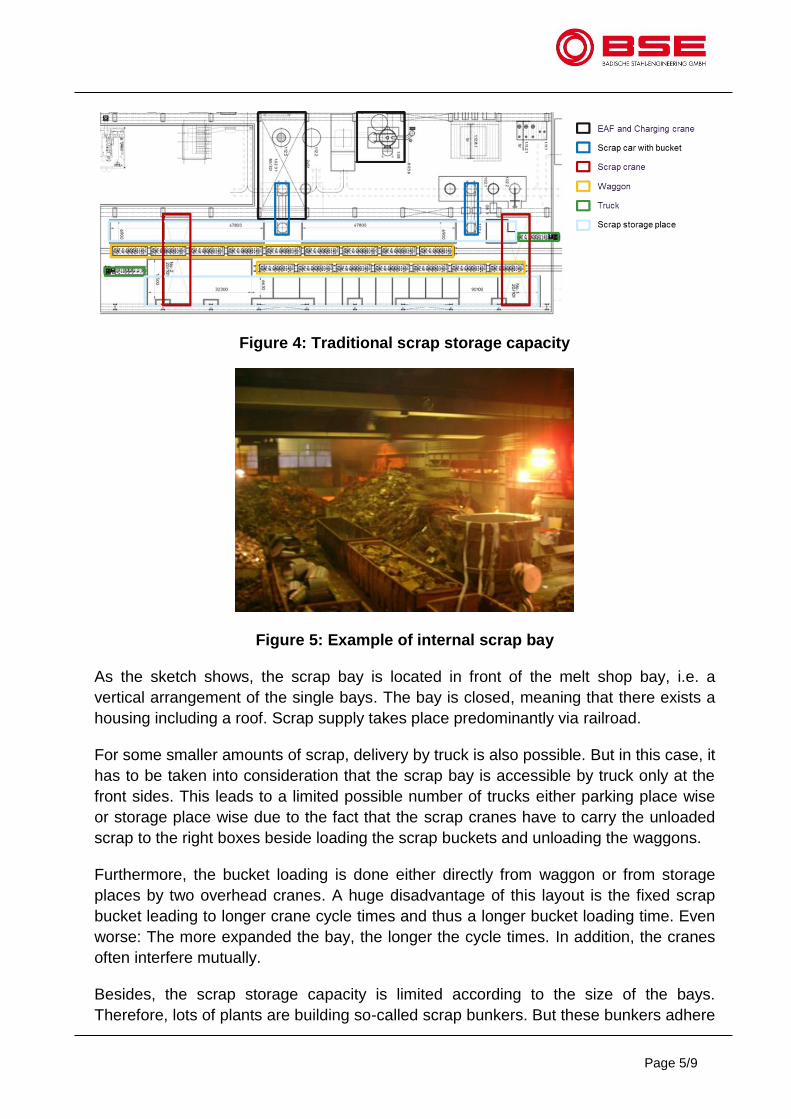
The first layout (Figure 4) shows a traditional scrap bay built inside the melt shop as a
single bay with fixed scrap car. This layout is very common in the steel industry
worldwide.
Page 5/9
Figure 4: Traditional scrap storage capacity
Figure 5: Example of internal scrap bay
As the sketch shows, the scrap bay is located in front of the melt shop bay, i.e. a
vertical arrangement of the single bays. The bay is closed, meaning that there exists a
housing including a roof. Scrap supply takes place predominantly via railroad.
For some smaller amounts of scrap, delivery by truck is also possible. But in this case, it
has to be taken into consideration that the scrap bay is accessible by truck only at the
front sides. This leads to a limited possible number of trucks either parking place wise
or storage place wise due to the fact that the scrap cranes have to carry the unloaded
scrap to the right boxes beside loading the scrap buckets and unloading the waggons.
Furthermore, the bucket loading is done either directly from waggon or from storage
places by two overhead cranes. A huge disadvantage of this layout is the fixed scrap
bucket leading to longer crane cycle times and thus a longer bucket loading time. Even
worse: The more expanded the bay, the longer the cycle times. In addition, the cranes
often interfere mutually.
Besides, the scrap storage capacity is limited according to the size of the bays.
Therefore, lots of plants are building so-called scrap bunkers. But these bunkers adhere
Page 6/9
to other problems like further increase of cycle time, dirt accumulating at the bunker‘s
bottom, difficult cleaning and the use of magnets will compress the scrap in the
bunkers.
The fixed scrap bucket is moved by a scrap car on rails to the melt shop bay and
afterwards emptied via charging crane in the EAF. In general, this traditional layout
often implies double handling: The scrap cranes have to load the scrap buckets and
empty the waggons. Very often, each waggon carries a different kind of scrap. The
waggons are then unloaded according to the bucket’s charging recipe. As a
consequence, not every waggon is unloaded at the same time in general. Thus,
sometimes waggons carrying types of scrap not used so often have to leave the scrap
bay partly still loaded, because other scrap types are missing and the scrap crane has
no time to unload it into the scrap storage place. This causes lots of problems, delays
and double handling.
Scrap yard with movable rail-bounded scrap bucket
Figure 6: Scrap yard with movable rail-bounded scrap bucket
Figure 7: Example of scrap yard with movable rail-bounded scrap bucket
Page 7/9
The second layout (Figure 6) shows a scrap yard with movable rail-bounded scrap
bucket. The scrap yard located in front of the melt shop bay is open, i.e. without roof.
The material flow from scrap yard to melting area is thus organised in a horizontal way.
This time, the storage place is also easily accessible via truck, not only rail. Thus, this
layout successfully combines scrap supply by rail and truck. In the scrap bay, the
railroads of the scrap bucket transfer car are merged in order to save space and thus
increase the yard’s storage capacity. Both scrap cranes and scrap buckets are
movable:
The scrap bucket that can be moved by a scrap car to the single scrap storages
The scrap car including the scrap bucket is remote-controlled by the crane driver
and moving between railroads and storage boxes
As a result, the crane driver can easily move the scrap bucket to the scrap quality he
needs.
A huge advantage of this scrap yard design is that the cycle time of the crane and thus
loading time of the bucket decreases. However, the scrap storage capacity is still
limited due to the limited overhead crane width (standard for this kind of scrap bays
amounts to 31 m, maximum 35.5 m), but can be extended by scrap bunkers, 2 opposed
bays or a lengthened scrap bay, which then leads to a longer scrap bucket loading time!
The fully loaded scrap bucket is transferred by the scrap car to the melting bay on
railroad.
Flexible scrap yard
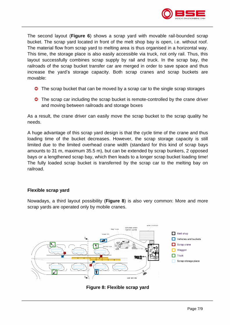
Nowadays, a third layout possibility (Figure 8) is also very common: More and more
scrap yards are operated only by mobile cranes.
Figure 8: Flexible scrap yard
Page 8/9
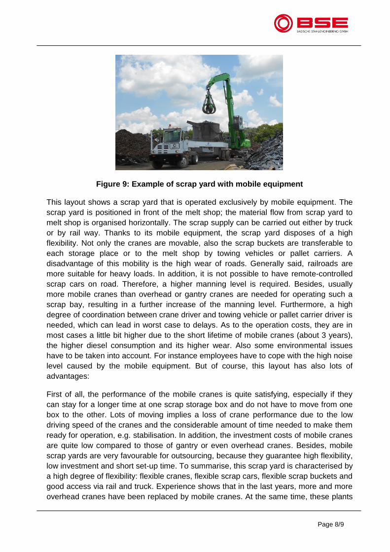
Figure 9: Example of scrap yard with mobile equipment
This layout shows a scrap yard that is operated exclusively by mobile equipment. The
scrap yard is positioned in front of the melt shop; the material flow from scrap yard to
melt shop is organised horizontally. The scrap supply can be carried out either by truck
or by rail way. Thanks to its mobile equipment, the scrap yard disposes of a high
flexibility. Not only the cranes are movable, also the scrap buckets are transferable to
each storage place or to the melt shop by towing vehicles or pallet carriers. A
disadvantage of this mobility is the high wear of roads. Generally said, railroads are
more suitable for heavy loads. In addition, it is not possible to have remote-controlled
scrap cars on road. Therefore, a higher manning level is required. Besides, usually
more mobile cranes than overhead or gantry cranes are needed for operating such a
scrap bay, resulting in a further increase of the manning level. Furthermore, a high
degree of coordination between crane driver and towing vehicle or pallet carrier driver is
needed, which can lead in worst case to delays. As to the operation costs, they are in
most cases a little bit higher due to the short lifetime of mobile cranes (about 3 years),
the higher diesel consumption and its higher wear. Also some environmental issues
have to be taken into account. For instance employees have to cope with the high noise
level caused by the mobile equipment. But of course, this layout has also lots of
advantages:
First of all, the performance of the mobile cranes is quite satisfying, especially if they
can stay for a longer time at one scrap storage box and do not have to move from one
box to the other. Lots of moving implies a loss of crane performance due to the low
driving speed of the cranes and the considerable amount of time needed to make them
ready for operation, e.g. stabilisation. In addition, the investment costs of mobile cranes
are quite low compared to those of gantry or even overhead cranes. Besides, mobile
scrap yards are very favourable for outsourcing, because they guarantee high flexibility,
low investment and short set-up time. To summarise, this scrap yard is characterised by
a high degree of flexibility: flexible cranes, flexible scrap cars, flexible scrap buckets and
good access via rail and truck. Experience shows that in the last years, more and more
overhead cranes have been replaced by mobile cranes. At the same time, these plants
Page 9/9
also decided to outsource their yards. This shows that mobile cranes and outsourcing
are closely linked together.
Conclusion
When looking for the layout of the optimal scrap storage facility or when comparing
different layouts with each other, various criteria have to be considered:
Capital and operational expenditure
Logistics and infrastructure, such as storage capacity, ways of scrap delivery,
crane performances and way of bucket transfer
Reliability of equipment like scrap cranes and transportation vehicles
Others such as required manpower, environmental issues and the flexibility to
adapt to a changing environment
At the end of the day, each steel plant will have particularities that have to be taken into
consideration when evaluating a plant’s layout and its ability to serve a highly
productive steel plant. For sure, the perfect scrap storage facility can be rarely found:
Either the premises and conditions on-site do not allow building the optimal solution, or
too less attention has been paid to this topic when building the plant. Experience shows
that mistakes done in the planning phase of a scrap storage facility very often lead to
technical bottlenecks and higher operation costs the plants have to live with day by day.
Moreover, there is very often no possibility to eliminate the drawbacks in a late stage.
Thus it really makes sense to spend enough time in the planning phase on the material
flow topic in order to save delay time when being into operation.
In addition, it is worth to analyse the scrap yard logistics and operation methods in
place very carefully during the operation phase. By doing this, almost every plant
around the world will get pretty sure aware of neglected improvement and thus saving
potentials.
And never forget: The success of every steel plant starts at the scrap yard!
We are Steelmakers!
Consulting & Qualification
Tools & Equipment
Engineering & Projects
Services & Spare Parts
BSW and BSE – a unique partnership that will help you to reach even ambitious goals.
Since 1983, the Badische Stahl-Engineering GmbH (BSE) has been acting as a service provider for increasing the efficiency and productivity in the electric steel industry world-wide.
BSE is a sister company of the Badische Stahl-werke GmbH (BSW), one of the world’s most efficient Electric Arc Furnace steel plants.
This unique partnership between BSW and BSE ensures that all products and services provided by BSE are not just based on meretheory, but on more than 4 decades of ownproven operational experience.