Analysis of Slurry Drying in a Spray Dryer Wittaya Julklang # , Boris Golman #1 # School of Chemical Engineering, Institute of Engineering, Suranaree University of Technology Nakhon-Ratchasima, 3000 Thailand 1 Corresponding author: [email protected]Abstract—Spray drying has recently been exploited to prepare a large variety of high-value particles. The aim of the present paper is to analyze the drying mechanism of slurry droplets consist of nanosized particles in an industrial-scale spray dryer. For this purpose, a mathematical model is developed comprising a comprehensive model for the heat and mass transfer for a single droplet and a model for the flow of droplets and gas, and the heat and mass transfer in the dryer. Using the developed model, the drying behaviour of slurry droplets in the spray dryer is investigated in the initial heating-up, constant rate and falling rate periods by analyzing the profiles of air temperature and humidity, and the droplet velocity, average temperature and moisture content in the dryer axial direction as well as the distributions of temperature and water vapor concentration in the droplet. Keyword-Slurry Drying, Spray Dryer, Drying Kinetics, Heat and Mass Transfer, Modelling I. INTRODUCTION Recently, engineered particles in the nanometer and submicrometer size ranges have found widespread applications in various technological and medical fields [1]. A large variety of functional micro/nanostructured particles have been reported in the literature, including magnetic nanoparticles for biomedical applications [2], silver and magnetite hybrid nanoparticles catalyst for reduction reaction of organic dyes in water [3], copper nanoparticle/polymer composites with antifungal and bacteriostatic properties [4], nanobiocatalytic assemblies for artificial photosynthesis [5], titania nanotubes for dye-synthesized solar cells [6], nanofood [7] and nanocomposites for aircraft industry [8], just to mention a few. However, a high surface energy and a great specific surface area of nanoparticles lead to their cohesion and agglomeration making particles handling in dry phase on industrial scale a particularly difficult task [9]. To overcome this impediment, the agglomerates of nanoparticles of enhanced flowability were produced using a spray drying technology [10]. Lately, the agglomerates of controlled porous structure were manufactured for high-value functional materials by tuning the spray drying apparatus and operational parameters [11]. In a typical spray drying operation, a slurry feed is sprayed into a drying chamber where the hot stream of the drying medium of low moisture content is supplied. Atomization of the feed into small droplets generates the large surface area for heat and mass transfer. Heat supplied by drying medium is used for evaporation of liquid within the droplets and the generated vapor is transferred to the medium. The drying rate, and the droplet morphology and porous structure are influenced by the rate of heat, mass and momentum transfer between the droplet and the drying gas as well as the heat and mass transfer inside the partially dried droplets. The drying mechanism is defined by the process conditions, slurry composition and droplets trajectories in the dryer chamber [12]. References [13] and [14] reported the model of spray dryer including the overall mass and energy balances. The uniform gas conditions where assumed in the well-mixed dryer. However, the well-mixed dryer models are oversimplified as they do not take into account distributions of temperature, humidity and velocity of drying medium and droplets in the drying chamber. Thus, they are not suitable for the analysis of drying mechanism of high value particles. The parallel flow model for spray dryers was reported in [15] and has been used by a number of authors [16], [17], [18] and [19]. The drying chamber was divided into the small control volumes. The equation of droplet trajectory has been involved together with the equations of heat and mass balances for droplet and drying gas. However, simple correlations were utilized to model the drying kinetics of a droplet. The parallel flow model was extended in [20] by using combinations of well-mixed and parallel-flow zones, or the axial dispersion model. The first problem with such combinations is that they require accurate measurements to be performed in existing dryers to identify the model parameters. Therefore, they are unsuitable for designing new drying chambers. The second problem was that combinations of well-mixed and parallel flow zones were often not unique, with a variety of fitted combinations being equally good representations. The third problem was that the fitted combinations were typically not generally applicable to scale up, scale down, different geometries or even changing operating conditions. The computational fluid dynamic (CFD) approach was utilized in [21] to describe the fluid flow within the spray drying chamber. The discrete approximations were used to solve the time-averaged conservation Wittaya Julklang et.al / International Journal of Engineering and Technology (IJET) ISSN : 0975-4024 Vol 5 No 6 Dec 2013-Jan 2014 5178
Transcript
Analysis of Slurry Drying in a Spray Dryer Wittaya Julklang#, Boris Golman#1
#School of Chemical Engineering, Institute of Engineering, Suranaree University of Technology Nakhon-Ratchasima, 3000 Thailand
Abstract—Spray drying has recently been exploited to prepare a large variety of high-value particles.
The aim of the present paper is to analyze the drying mechanism of slurry droplets consist of nanosized particles in an industrial-scale spray dryer. For this purpose, a mathematical model is developed comprising a comprehensive model for the heat and mass transfer for a single droplet and a model for the flow of droplets and gas, and the heat and mass transfer in the dryer. Using the developed model, the drying behaviour of slurry droplets in the spray dryer is investigated in the initial heating-up, constant rate and falling rate periods by analyzing the profiles of air temperature and humidity, and the droplet velocity, average temperature and moisture content in the dryer axial direction as well as the distributions of temperature and water vapor concentration in the droplet.
Keyword-Slurry Drying, Spray Dryer, Drying Kinetics, Heat and Mass Transfer, Modelling
I. INTRODUCTION
Recently, engineered particles in the nanometer and submicrometer size ranges have found widespread applications in various technological and medical fields [1]. A large variety of functional micro/nanostructured particles have been reported in the literature, including magnetic nanoparticles for biomedical applications [2], silver and magnetite hybrid nanoparticles catalyst for reduction reaction of organic dyes in water [3], copper nanoparticle/polymer composites with antifungal and bacteriostatic properties [4], nanobiocatalytic assemblies for artificial photosynthesis [5], titania nanotubes for dye-synthesized solar cells [6], nanofood [7] and nanocomposites for aircraft industry [8], just to mention a few.
However, a high surface energy and a great specific surface area of nanoparticles lead to their cohesion and agglomeration making particles handling in dry phase on industrial scale a particularly difficult task [9]. To overcome this impediment, the agglomerates of nanoparticles of enhanced flowability were produced using a spray drying technology [10]. Lately, the agglomerates of controlled porous structure were manufactured for high-value functional materials by tuning the spray drying apparatus and operational parameters [11].
In a typical spray drying operation, a slurry feed is sprayed into a drying chamber where the hot stream of the drying medium of low moisture content is supplied. Atomization of the feed into small droplets generates the large surface area for heat and mass transfer. Heat supplied by drying medium is used for evaporation of liquid within the droplets and the generated vapor is transferred to the medium.
The drying rate, and the droplet morphology and porous structure are influenced by the rate of heat, mass and momentum transfer between the droplet and the drying gas as well as the heat and mass transfer inside the partially dried droplets. The drying mechanism is defined by the process conditions, slurry composition and droplets trajectories in the dryer chamber [12].
References [13] and [14] reported the model of spray dryer including the overall mass and energy balances. The uniform gas conditions where assumed in the well-mixed dryer. However, the well-mixed dryer models are oversimplified as they do not take into account distributions of temperature, humidity and velocity of drying medium and droplets in the drying chamber. Thus, they are not suitable for the analysis of drying mechanism of high value particles.
The parallel flow model for spray dryers was reported in [15] and has been used by a number of authors [16], [17], [18] and [19]. The drying chamber was divided into the small control volumes. The equation of droplet trajectory has been involved together with the equations of heat and mass balances for droplet and drying gas. However, simple correlations were utilized to model the drying kinetics of a droplet.
The parallel flow model was extended in [20] by using combinations of well-mixed and parallel-flow zones, or the axial dispersion model. The first problem with such combinations is that they require accurate measurements to be performed in existing dryers to identify the model parameters. Therefore, they are unsuitable for designing new drying chambers. The second problem was that combinations of well-mixed and parallel flow zones were often not unique, with a variety of fitted combinations being equally good representations. The third problem was that the fitted combinations were typically not generally applicable to scale up, scale down, different geometries or even changing operating conditions.
The computational fluid dynamic (CFD) approach was utilized in [21] to describe the fluid flow within the spray drying chamber. The discrete approximations were used to solve the time-averaged conservation
Wittaya Julklang et.al / International Journal of Engineering and Technology (IJET)
ISSN : 0975-4024 Vol 5 No 6 Dec 2013-Jan 2014 5178
equations applying a concept known as the Particle Source-in-Cell or discrete droplet model. This concept essentially involves treating the gas as a continuous phase and the spray as a discrete tracked phase. The effects of the droplets are initially neglected when calculating the axial, radial and tangential components of the gas velocities. Reference [22] reported one of the first careful and complete CFD studies of flow patterns in spray dryers, finding that the values of the turbulence parameters selected at the annular air inlet of the dryer affected the predictions of the air flow patterns significantly and that the availability of experimental measurements of these parameters is often limited. Hence either the parameters need to be obtained from a separate numerical simulation of the air inlet or they must be treated as fitting parameters, which reduces the predictive power of the model for design purposes. The development of powerful workstations at a reasonable cost has enabled the expanded use of CFD. However, the CFD model is commonly combined with the simple model of drying kinetics of the slurry droplet due to the prohibitively long calculation time.
An in-depth understanding of the drying behavior of a single feed droplet is essential for the design of a spray dryer. The drying kinetics of droplets including solid particles inside is usually described separately for two drying periods [23]. Water evaporates from the outer surface of the slurry droplet at constant rate as a result of heat transfer from surrounding gas by convective flow during the first period of drying. The liquid evaporation results in droplet diameter shrinking and simultaneous increase of solid concentration inside the droplet. The evaporation lead to solid commencing at the surface of the droplet and, eventually, the surface becomes covered with a layer of solid component called a crust [24]. This is a beginning of the second, falling rate, period of drying. In this period, the evaporation is taking place inside the wet particle and the drying process is hindered by the addition of heat and mass transfer resistances in the particle due to an increase of crust layer thickness.
The comprehensive mathematical model of spray drying of a slurry droplet was developed and validated in our previous studies [25, 26]. The temperature and moisture concentration distributions inside the crust and wet core regions were simulated taking into account both internal and external mass and heat transfer resistances during the constant and falling rate periods.
The objectives of the present study are to develop a model of spray dryer, including the comprehensive model of drying kinetics of a slurry droplet, and to investigate the drying mechanism of slurry droplets of nanoparticles in the industrial-scale dryer.
II. THEORETICAL
A. Modelling of Slurry Drying in Spray Dryer Chamber
The drying medium model is formulated taking into account the heat, mass and momentum exchange between droplets and the drying medium in the chamber. The droplet velocity distributions in the drying chamber are obtained by solving the system of force-balance equations. The heat and mass balances around the shell in the chamber yield the distributions of humidity and temperature of drying medium along the chamber height.
1) Droplet Formation in Atomization Process: A centrifugal-pressure nozzle commonly used in industry is adopted in the present simulation. A spray of droplets is created by forcing the slurry feed under pressure through an orifice. The slurry feed is supplied in such a way that it forms a pattern of swirling motion in the nozzle. Droplets leaving the nozzle spread radially outward forming a hollow cone spray. We can assume that the droplet velocity will have two predominant components, one is axial
pxU and the other is tangentialptU .
The axial droplet velocity as a function of slurry feed rate can be calculated as [12]
o2
slpx
sl
wU
r b , (1)
where or is the orifice radius, slw is the mass flow rate of slurry, sl is the slurry density and b is the thickness
of the slurry film in the nozzle exit orifice. In general, the slurry film thickness ranges from 0.1 to 0.3 of the orifice diameter.
The slurry density is defined as
1( )
s lsl
l sl sl sX X
, (2)
where slX is the moisture content of slurry, s and l are the densities of solid and liquid phases,
respectively. Taking into account the nozzle geometry, it can be assumed that the droplet leaving a nozzle travels along a
straight line at an angle to the nozzle axis. Therefore, the half spray angle is defined as
Wittaya Julklang et.al / International Journal of Engineering and Technology (IJET)
ISSN : 0975-4024 Vol 5 No 6 Dec 2013-Jan 2014 5179
1tan pt
px
U
U
(3)
Consequently, the tangential velocity is expressed as tanpt pxU U (4)
2) Droplet Trajectories in the Dryer: The droplet trajectories are obtained by solving the system of force-balance equations.
3 1
14
g D p px gxpx g
p p p px
C U U UdUg
dh d U
(5)
2
3
1
4
g D p pr grpr pt
c p p px
C U U UdU U
dh r d U
(6)
3 1
4
g D p pt gtpt pr pt
c p p px
C U U UdU U U
dh r d U
, (7)
where h is the height of the drying chamber, cr is the radial position of droplets in the drying chamber, pU is
the relative droplet velocity, prU is the droplet radial velocity, giU is the i-component of drying medium velocity,
DC is the drag force coefficient, pd is the droplet diameter, g and p are the gas and droplet densities,
respectively. The relative droplet velocity can be calculated as
1/22 2 2
p px gx pr gr pt gtU U U U U U U (8)
The radial location of droplets is determined by the following equation
prc
px
Udr
dh U (9)
Here, the air flow pattern is presumed to be flat in the radial direction of the drying chamber, i.e. 0gr gtUU .
The following empirical equation is used to evaluate the drag force coefficient [27]
1/
,
ccc
Da
C bRe
(10)
with constants 24, 0.32a b and 0.52c .
3) Mass and Heat Balances of Drying Medium in the Dryer: The mass balance over the shell in the drying chamber is formulated as
,0 gas sl dsl
gas gas
dw dXY Y wdY
dh w dh w dh
, (11)
where gasw is the mass flow rate of drying medium on dry basis, 0Y is the humidity of drying medium at inlet
conditions, Y is the humidity of drying medium, ,sl dX is the droplet moisture content on wet basis and
/gasdw dh is the term to account for expansion of spray.
The distribution of temperature of drying medium along the height of the drying chamber is derived as
,0
,, ,
1
(1 ) ( )
gas gasgas gas gas lv gas l
gas H
sl dslsl sl d l sl d s sl l s sl
dT dw dYi i w Cp T
dh w Cp dh dh
dXdTw X Cp X Cp w Cp Cp T
dh dh
, (12)
where gasT is the gas temperature, slT is the slurry temperature, gasi is the enthalpy of drying medium, ,0gasi is
the enthalpy of drying media at inlet conditions, l is the latent heat of vaporization, and lCp , sCp , gasCp and
Wittaya Julklang et.al / International Journal of Engineering and Technology (IJET)
ISSN : 0975-4024 Vol 5 No 6 Dec 2013-Jan 2014 5180
lvCp are the specific heat capacities of liquid, solid, drying medium and liquid vapor, respectively. Here, HCp
is the specific heat capacity of humid media, H gas lvCp Cp Cp Y .
The term to account for expansion of spray, /gasdw dh , can be determined on the basis of the increment of
stream cross-section as [28]
21
gas gx gdw U drr
dh Y dh
(13)
B. Modelling of a Slurry Droplet Drying
The spray drying process is commonly divided into two periods corresponding to the constant and falling drying rates. The drying model of a slurry droplet is derived separately for each period.
1) Constant Rate Period: To set up the drying model in the constant rate period, the droplet is separated into two regions [29]. The first region is a wet core, which occupies the central part of the droplet from 0r to inr R , and solid particles are located in this part of the droplet. The second region from inr R to outr R is
a free liquid, with the most liquid appear in this part.
The temperature distribution in the wet core region is described by the following partial differential equation
22
1(1 )co co
co l l s s
T Tr k Cp Cp
r r tr
, (14)
where coT is the wet core temperature, t is the time, r is the radial position in the droplet, is the porosity of
agglomerated product and cok is the heat conductivity of wet core.
The boundary conditions for Eq. (14) are derived by assuming the continuous temperature profile at the boundary of wet core and free liquid regions and the absence of the temperature gradient at the droplet center.
0
a 0ndin in
coco lr R r R
r
TT T
r
, (15)
where lT is the temperature in the free liquid region.
The temperature distribution in the free liquid region is given as
22
1 l ll l l
T Tr k Cp
r r tr
, (16)
where lk is the thermal conductivity of liquid phase.
Assuming the continuity of the heat flux across the boundary of free liquid and wet core regions, the boundary equation at inr R is obtained as
in in
l col co
r R r R
T Tk k
r r
(17)
The heat balance at the evaporation interface on the outer droplet surface, outR , is given as
out
l outl h l gas l l
r R
T dRk k T T
r dt
, (18)
where hk is the convective heat transfer coefficient.
The mass balance at the evaporation interface is written as
l outm lv gas
l
dRk C C
M dt
, (19)
where mk is the convective mass transfer coefficient, lM is the molecular weight of liquid, and lvC and gasC are
the vapor concentrations at the droplet surface and in the bulk phase, respectively.
2) Falling Rate Period: In the falling rate period, the evaporation takes place inside the agglomerated particle and the drying process is hindered by heat and mass transfer resistances inside the particle due to increasing crust thickness. The second drying period proceeds until the particle moisture content is reduced to an equilibrium value with the drying medium. At this moment, the drying process actually stops and then particle is heated up to the final temperature.
The particle in the falling rate period is separated into two regions: a wet core from 0r to r s and a dry crust from r s to inr R . The energy balance over the shell of wet core region is derived as
Wittaya Julklang et.al / International Journal of Engineering and Technology (IJET)
ISSN : 0975-4024 Vol 5 No 6 Dec 2013-Jan 2014 5181
22
1(1 )co co
co l l s s
T Tr k Cp Cp
r r tr
(20)
The boundary conditions are
0
and0coco crr s r s
r
TT T
r
, (21)
where crT is the dry crust temperature.
The temperature distribution in the radial direction of the dry crust layer composed of solid structure and pore space is described as
22
11cr
cr s s cr
Tr k Cp T
r r tr
, (22)
where crk is the thermal conductivity of dry crust.
The vapor concentration in the crust layer is given as
2
2
1 lvlvcr
CCr D
r r tr
, (23)
where lvC is the concentration of liquid vapor and crD is the effective diffusivity of dry crust.
The boundary conditions for Eqs. (22) and (23) at the evaporation surface r s separating the crust layer and wet core are
cr col l cr co
T Tdsk k
dt r r
(24)
and
lvl cr l
CdsD M
dt r
(25)
The heat and mass balances on the outer droplet surface inr R are
in
crcr h cr gas
r R
Tk k T T
r
(26)
and
in
lvcr m lv gas
r R
CD k C C
r
(27)
The droplet moisture content is calculated as
3
,
4 11
3in s
sl dd
RX
W
(28)
Here, the droplet weight dW is a function of position of evaporation interface s
3 341
3d l s inW s R (29)
The average droplet temperature is obtained by integration of temperature distributions in the crust layer and wet core
2av 3 0
3( )
inR
in
T r T r drR
(30)
3) Physical Properties and Correlations: The heat conductivity of wet core is defined as [30] (1 )co l sk k k (31)
The heat conductivity of dry crust region is given as (1 )cr mx sk k k (32)
The heat conductivity of air-water mixture is evaluated as [31] 2 5 8 2 12 32.425 10 7.899 10 1.790 10 8.570 10mxk T T T (33)
where temperature is given in degrees Celsius. The effective diffusivity of water vapor in dry crust is calculated as [32]
2
3wv
cr
DD
(34)
Wittaya Julklang et.al / International Journal of Engineering and Technology (IJET)
ISSN : 0975-4024 Vol 5 No 6 Dec 2013-Jan 2014 5182
and the diffusivity of water vapor is given as
1.75
40.22 10273.15wv
TD
, (35)
where temperature is given in degrees Kelvin. The density, viscosity, heat capacity and heat conductivity of air are estimated as [29]
5 8
2 5 2 9 3
5
273.151.2929
273.15
1.720 10 4.568 10
969.542 6.801 10 16.569 10 67.828 10
1.731 0.014 4.296 10
gas
gas
gas
gas
T
T
Cp T T T
k T
, (36)
where temperature is given in degrees Celsius for all correlations except the one for gasCp .
The correlation for the latent heat of evaporation is [29] 6 33.15 10 2.38 10l T , (37)
where temperature is given in degrees Celsius. The thermodynamic properties of water are calculated using the subset of equations developed for industrial
use by the International Association for the Properties of Water and Steam, IAPWS-IF97 [33]. The convective heat and mass transfer coefficients are calculated by utilizing Ranz and Marshall
correlations [34]
1/ 2 1/3Nu·
, Nu 2 0.65·Re Prgash
p
kk
d (38)
1/ 2 1/3Sh·, Sh 2 0.65·Re Scwv
mp
Dk
d , (39)
where Nu , Sh , Re , Pr and Sc are the Nusselt, Sherwood, Reynolds, Prandtl and Schmidt numbers for drying air, respectively. These dimensionless numbers are defined as
Re , Pr , Scgas p gas gas gas gas
gas gas gas wv
d U Cp
k D
(40)
III. NUMERICAL APPROACH
The spray drying chamber is divided into small control volumes along the axial distance. The control volume is small enough to assume the temperature, humidity and velocity of drying medium to be constant. The drying model of a slurry droplet is then used in each volume for calculation of heat and mass transfer between the drying medium and the droplets. The droplet moisture content and the average temperature are calculated using the moisture and temperature distributions in the radial direction of the droplet by Eqs. (29) and (30). The system of partial and ordinary differential equations with moving boundary was solved numerically by a finite difference method using an implicit scheme [35, 29].
IV. RESULTS AND DISCUSSION
C. Simulation Setup
In this paper, computer simulation studies were conducted on the drying behavior of slurry droplets in an industrial-scale spray dryer with a chamber consisting of an upper cylindrical and lower conical sections. The chamber diameter is 2.215 m, the height of the cylindrical section is 2.005 m and the total height of the dryer is 3.730 m [36].
The dryer is equipped with a centrifugal pressure nozzle with an orifice of diameter of 0.000711 m. The droplets of uniform size are assumed to form a cone with a half angle of 38o during spraying [37]. Drying gas supplied from the top of the dryer concurrently with the slurry feed is distributed uniformly in the radial direction of the dryer.
The spray drying of the slurry droplet of nanosized silica particles was investigated in the present study. A summary of operational conditions is given in Table I.
Wittaya Julklang et.al / International Journal of Engineering and Technology (IJET)
ISSN : 0975-4024 Vol 5 No 6 Dec 2013-Jan 2014 5183
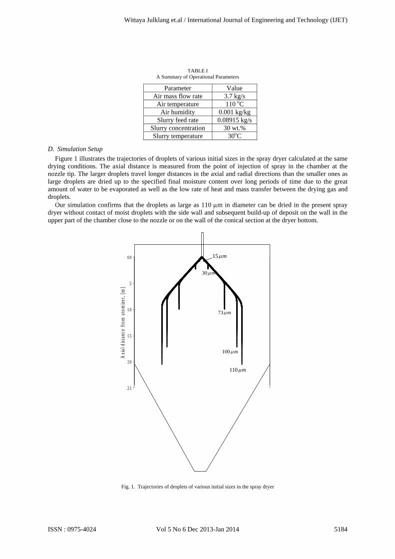
Figure 1 illustrates the trajectories of droplets of various initial sizes in the spray dryer calculated at the same drying conditions. The axial distance is measured from the point of injection of spray in the chamber at the nozzle tip. The larger droplets travel longer distances in the axial and radial directions than the smaller ones as large droplets are dried up to the specified final moisture content over long periods of time due to the great amount of water to be evaporated as well as the low rate of heat and mass transfer between the drying gas and droplets.
Our simulation confirms that the droplets as large as 110 m in diameter can be dried in the present spray dryer without contact of moist droplets with the side wall and subsequent build-up of deposit on the wall in the upper part of the chamber close to the nozzle or on the wall of the conical section at the dryer bottom.
Axi
al d
ista
nce
from
ato
miz
er, [
m]
0.0
.5
1.0
1.5
2.0
2.5
15 m
30 m
73 m
110 m
100 m
Fig. 1. Trajectories of droplets of various initial sizes in the spray dryer
Wittaya Julklang et.al / International Journal of Engineering and Technology (IJET)
ISSN : 0975-4024 Vol 5 No 6 Dec 2013-Jan 2014 5184
Figure 2 shows the variation of the average droplet temperature with drying time and axial distance from the nozzle. The symbols (a), (b), (c), (d) and (e) are used to illustrate the relationship between the drying time and the drying distance of droplets in the spray dryer. The symbol (a) corresponds to the initial heating-up, (b) to the constant rate, and (c), (d) and (e) to the falling rate periods, respectively. The duration of the initial heating-up period of droplets is very short, as the droplets are quickly heated up from the inlet temperature up to the wet bulb temperature. However, droplets will travel long distances during the initial period owing to their high injection velocity from the nozzle.
(a)
(b)
(c)
(d)
(e)
Radial distance from nozzle, [m]
0.0 .2 .4 .6 .8 1.0
Axi
al d
ista
nce
from
noz
zle,
[m
]
0.0
.5
1.0
1.5
2.0
(a)
(b)
(c)
(d)
(e)
Drying time, [s]
0.0 .1 .2 .3 .4 .5 .6
Ave
rage
dro
plet
tem
pera
ture
, [oC
]
28
30
32
34
36
38
40
42
44
46
48
(a) (b)
(c)
(d)
(e)
Axial distance from nozzle, [m]
0.0 .2 .4 .6 .8 1.0 1.2
Ave
rage
dro
plet
tem
pera
ture
, [oC
]
28
30
32
34
36
38
40
42
44
46
48
(a)(b)
(c)
(d)
(e)
(a)
(b)
Fig. 2. The variation of the average droplet temperature with (a) drying time and (b) axial distance
Figure 3 illustrates the axial and radial droplet velocity profiles in the axial direction of the dryer. After the
droplet reaches its maximum radial distance, the droplet radial velocity falls to zero and the axial velocity drops to air velocity to follow the balance of forces acting on the droplet.
As the temperature, humidity and velocity of drying air surrounding droplets alter with drying time, the drying behavior of the droplet in the dryer differ from one at constant drying conditions, [25]-[26], even the drying mechanisms are similar.
Wittaya Julklang et.al / International Journal of Engineering and Technology (IJET)
ISSN : 0975-4024 Vol 5 No 6 Dec 2013-Jan 2014 5185
Axial distance from nozzle, [m]
0.0 .5 1.0 1.5 2.0
Vel
ocity
, [m
/s]
0
50
100
150
200
250
0.0 .2 .4 .6 .8 1.0
0.0
.5
1.0
1.5
2.0
Axial droplet velocityAir velocity
(a)
Axial distance from nozzle, [m]
0.0 .5 1.0 1.5 2.0
Vel
ocit
y, [
m/s
]
0
50
100
150
200
0.0 .2 .4 .6 .8 1.0
0.0
.5
1.0
1.5
2.0
Radial droplet velocityAir velocity
(b)
Fig. 3. Velocity profiles of droplets: (a) axial and (b) radial
Figure 4 shows the average temperature and moisture content of droplets in the cylindrical section of the
spray dryer. The temperature of droplets increases rapidly up to the wet bulb temperature after they leave the nozzle due to the efficient heat transfer from the drying air. However, droplets travel around 0.5 m from the nozzle tip along the chamber height during this period as the initial droplet velocities are high both in the axial and radial directions. Only a small amount of water is evaporated from the droplet surface in this period, as confirmed in Fig. 4 by the minor decline of droplet moisture content. As a result, the temperature of drying air slightly decreases and humidity increases, as shown in Fig. 5.
During the constant rate period, all heat supplied to droplets by drying air is consumed on water evaporation in the droplets. The air temperature quickly decreases and humidity increases in this period. The droplets travel a short distance along the chamber height because the droplet velocity is very low in comparison with the one in the heating-up period. The droplet velocity in this period is quite close to the air velocity and the droplets have more time for heat and mass exchange with drying air.
After the constant rate period ends, the evaporation will take place inside the droplet and the drying mechanism switches to the falling rate period. The evaporation rate declines in this period, as confirmed by the
Wittaya Julklang et.al / International Journal of Engineering and Technology (IJET)
ISSN : 0975-4024 Vol 5 No 6 Dec 2013-Jan 2014 5186
drop in the rate of change of droplet moisture content in Fig. 4, since the heat and mass transfer between the evaporation interface and the drying air is hindered by the growing crust layer. A certain amount of heat accumulates in the crust resulting in a decrease of the heat supply to the evaporation interface. This leads to an increase of the average droplet temperature with drying time.
Axial distance from nozzle, [m]
0.0 .5 1.0 1.5 2.0
Ave
rage
dro
plet
tem
pera
ture
, [o C
]
28
30
32
34
36
38
40
42
44
46
48
Dro
plet
moi
stur
e co
nten
t, [k
g/kg
]
0.0
.2
.4
.6
.8
Fig. 4. Profiles of droplet average temperature and moisture content in the cylindrical section of spray dryer
Axial distance from nozzle, [m]
0.0 .5 1.0 1.5 2.0
Air
tem
pera
ture
, [o C
]
50
60
70
80
90
100
110
120
Air
hum
idity
, [kg
/kg]
0.000
.002
.004
.006
.008
.010
.012
.014
.016
.018
Fig. 5. Profiles of air temperature and humidity in the cylindrical section of spray dryer
Figure 6 illustrates the profiles of temperature and concentration of water vapor in the radial direction of the droplet at various drying times corresponding to the different drying mechanisms. The temperature profiles are nearly flat in the droplet during the initial heating-up and constant drying rate periods as there is no significant resistance to the heat transfer in the wet core containing solid particles dispersed in liquid.
In the heating-up period, the droplet temperature increases with time uniformly throughout the droplet until it reaches the wet bulb temperature. However, the droplet temperature does not change in the constant rate period as all supplied heat is consumed for evaporation of liquid at the outer droplet surface.
In the falling rate period, the temperature profile inside the droplet can be separated into two parts corresponding to the dry crust and wet core regions, as shown in Figs. 6 for drying times (c), (d) and (e). The temperature profile is flat in the wet core, but the temperature decreases in the radial direction of the dry crust
Wittaya Julklang et.al / International Journal of Engineering and Technology (IJET)
ISSN : 0975-4024 Vol 5 No 6 Dec 2013-Jan 2014 5187
region from the outer droplet surface to the evaporation interface due to the heat transfer resistance in the porous crust layer.
Figure 6 also illustrates the concentration profiles of water vapor in the droplet: (c) at the beginning, (d) in the middle and (e) at the end of the falling rate period. The heat and mass transfer resistances in the droplet are augmented with drying time due to the growing thickness of the dry crust layer. As a result, the temperature and concentration differences rise between the outer droplet surface and the evaporation interface.
(a)
(b)
(c)
(d)
(e)
Radial distance from nozzle, [m]
0.0 .2 .4 .6 .8 1.0
Axi
al d
ista
nce
from
noz
zle, [
m]
0.0
.5
1.0
1.5
2.0
(a)
(b)
(c)
(d)
(e)
Normalized droplet radius, [-]
0.0 .2 .4 .6 .8 1.0
Tem
pera
ture
, [o C
]
30
35
40
45
50
55
60
(a)(b)(c)(d)(e)
Temperature profile at position
Nomalized droplet radius, [-]
0.0 .2 .4 .6 .8 1.0
Con
cent
ratio
n of
wat
er v
apor
, [km
ol/m
3 ]
.0010
.0015
.0020
.0025
.0030
.0035
.0040
(c)(d)(e)
Concentrationprofile at position
Fig. 6. Temperature and concentration distributions in the droplet at various drying times
V. CONCLUSION
In the present study, a mathematical model was developed for spray drying of slurry droplets of nanoparticles in the industrial-scale spray dryer. The model is based on the combination of a model for the heat and mass transfer for a single droplet with a model for the flow of droplets and drying gas, and the heat and mass transfer in the spray dryer. The present model is capable to predict the profiles of droplet average temperature, moisture content and velocities along the axial distance of the dryer as well as the distributions of temperature and water vapor concentration inside the droplet at any axial dryer position.
The computer simulation studies were conducted on the drying mechanism of slurry droplets consist of nanosized particles in the industrial-scale spray dryer. Our simulation confirmed that the average droplet temperature increased rapidly up to the wet bulb temperature during the initial heating-up period due to the efficient heat supply from the drying air as a result of high initial droplet velocities in axial and radial directions.
The air temperature quickly decreased and humidity increased, but the average droplet temperature remained constant in the axial direction of the dryer during the constant rate period owing to evaporation from the outer droplet surface. The temperature distribution in the droplet was nearly uniform due to the low heat transfer resistance in the wet core.
The rates of change of the air temperature increased and humidity declined, and the average droplet temperature rose in the falling rate period because of the growing resistances to heat and mass transfer in the
Wittaya Julklang et.al / International Journal of Engineering and Technology (IJET)
ISSN : 0975-4024 Vol 5 No 6 Dec 2013-Jan 2014 5188
crust layer. As a result, the temperature and vapor pressure differences between the outer droplet surface and the evaporation interface expanded with drying time.
ACKNOWLEDGMENT
The authors would like to thank the National Research Council of Thailand for their funding of this research.
REFERENCES [1] T. Tsuzuki, “Applications and market opportunities of nanoparticulate materials,” in Nanotechnology Commercialization, T. Tsuzuki,
Ed. Boca Raton, USA: CRC Press, 2013. [2] J. Gao, H. Gu and B. Xu, “Multifunctional magnetic nanoparticles: design, synthesis, and biomedical applications,” Accounts of
Chemical Research, vol. 42, pp. 1097-1107, 2009. [3] H. Wang, J. Shen, Y. Li, Z. Wei, G. Cao, Z. Gai, K. Hong, P. Banerjee and S. Zhou, “Porous carbon protected magnetite and silver
hybrid nanoparticles: morphological control, recyclable catalysts, and multicolor cell imaging,” ACS Applied Materials & Interfaces, vol. 5, pp. 9446-9453, 2013.
[4] N. Cioffi, L. Torsi, N. Ditaranto, G. Tantillo, L. Ghibelli, L. Sabbatini, T. Bleve-Zacheo, M. D'Alessio, G. Zambonin and E.Traversa, Enrico, “Copper nanoparticle/polymer composites with antifungal and bacteriostatic properties,” Chemistry of Materials, vol. 17, pp. 5255-5262, 2005.
[5] J.H. Kim, H.N. Dong and C.B. Park, “Nanobiocatalytic assemblies for artificial photosynthesis,” Current Opinion in Biotechnology, vol. 28, pp. 1–9, 2014.
[6] G.-S. Kim, H.-K. Seo, V.P. Godble, Y.-S. Kim, O-B. Yang and H.-S. Shin, “Electrophoretic deposition of titanate nanotubes from commercial titania nanoparticles: Application to dye-sensitized solar cells,” Electrochemistry Communications, vol. 8, pp. 961–966, 2006.
[7] M. Das, N. Saxena and P.D. Dwivedi, “Emerging trends of nanoparticles application in food technology: Safety paradigms,” Nanotoxicology, vol. 3, pp. 10-18, 2009.
[8] M. Naffakh, A.M. Díez-Pascual, C. Marco, M.A. Gómez and I. Jiménez, “Novel melt-processable poly(ether ketone)(PEEK)/Inorganic fullerene-like WS2 nanoparticles for critical applications,” The Journal of Physical Chemistry B, vol. 114, pp. 11444-11453, 2010.
[9] S. Chattoraj, L. Shi, C.C. Sun, "Profoundly improving flow properties of a cohesive cellulose powder by surface coating with nano-silica through comilling", J Pharm Sci., vol. 100, pp. 4943-4952, 2011.
[10] K. Sollohub and K. Cal, “Spray drying technique: II. Current applications in pharmaceutical technology,” Journal of Pharmaceutical Sciences, Vol. 99, pp. 587–597, 2010.
[11] A.B. Nandiyanto and K.Okuyama, “Progress in developing spray-drying methods for the production of controlled morphology particles: From the nanometer to submicrometer size ranges,” Advanced Powder Technol., vol. 22, pp. 1-19, 2011.
[12] K. Masters, Spray Drying Handbook, Harlow, England: Longman Scientific and Technical, 1985. [13] R.B. Keey, Introduction to Industrial Drying Operations, Oxford, England: Pergamon Press, pp. 15-99, 1978. [14] C. Strumillo and T.Kudra, Drying: Principles, Application and Design, New York, USA: Gordon and Breach, pp. 45-54, 1986. [15] R.B. Keey and Q.T. Pham, “Behaviour of spray dryers with nozzle atomizers”, Chemical Engineer, vol. 311, pp. 516-521, 1976. [16] I. Zbicinski, “Development and experimental verification of momentum, heat and mass transfer model in spray drying”, Chemical
Engineering Journal, vol. 58, pp. 123-133, 1995. [17] V. Truong, B.R. Bhandari and T.Howes, “Optimization of co-current spray drying process of sugar-rich foods. Part I – Moisture and
glass transition temperature profile during drying”, Journal of Food Engineering, vol. 71, pp. 55-65, 2005. [18] D.L. Pearce, “A novel way to measure the concentration of a spray in a spray dryer”, Drying Technology, vol. 24, pp. 777-781, 2006. [19] D. Chiou, T.A.G. Langrish and R. Braham, “Partial crystallisation behaviour during spray drying: simulations and experiments”,
Drying Technology, vol. 26, 27-38, 2008. [20] D. Reay, “Fluid flow, residence time simulation and energy efficiency in industrial dryers”, In: Proceedings of the Sixth International
Drying Symposium (IDS ’88), Roques M., Ed., Versailles, France, pp. KL 1-KL 8, 1988. [21] C.T.Crowe, “Modelling spray-air contact in spray-drying systems”, In: Advances in Drying, Mujumdar, A.S., Ed., vol. 1, New York,
USA: Hemisphere, pp. 63-99, 1980. [22] D.E. Oakley, R.E. Bahu and D. Reay, “The aerodynamics of concurrent spray dryers”, In: Proceedings of the Sixth International Drying
Symposium (IDS ’88), Roques M., Ed., Versailles, France, pp. OP 373-OP 378, 1988. [23] T. Elperin and B. Krasovitov, “Evaporation of liquid droplets containing small solid particles”, Int. J. Heat Mass Transfer, vol. 38, pp.
2259-2267, 1995. [24] H. Charlesworth and W.R. Marshall, “Evaporation from drops containing dissolved solids”, AIChE Journal, vol. 6, pp. 9-23, 1960. [25] W. Julklang and B. Golman, “Influence of operational conditions on the drying kinetics of a slurry droplet in a spray dryer,”
Engineering Transactions, Vol. 15, pp. 59-65, 2012. [26] B. Golman and W. Julklang, “Analysis of drying kinetics of a slurry droplet in the falling rate period of spray drying”, World Academy
of Science, Engineering and Technology. International Journal of Chemical Science and Engineering, Vol. 7, pp. 801-805, 2013. [27] H.J. Holterman, “Kinetics and evaporation of water drops in air”, IMAG, Wageningen, Report no. 2003-12, 67 pp., 2003. [28] I. Zbiciński, “Development and experimental verification of momentum, heat and mass transfer model in spray drying”, The Chemical
Engineering Journal and the Biochemical Engineering Journal, vol. 58, pp. 123 - 133, 1995. [29] N. Dalmaz, H.O. Ozbelge, A.N. Eraslan, and Y. Uludag, “Heat and mass transfer mechanisms in drying of a suspension droplet: a new
computational model”, Drying Technology, Vol. 25, pp. 391-400, 2007. [30] X.D. Chen and X. Peng, “Modified Biot Number in the Context of Air Drying of Small Moist Porous Objects,” Drying Technology, vol.
23, pp. 83-103. [31] Z. Pakowski and A.S. Mujumdar, “Basic process calculations in drying”, in Handbook of industrial drying, USA:CRC Press, pp. 71-112,
1995. [32] J.A. Ochoa-Tapia, P. Stroeve and S. Whitaker, “Diffusive transport in two-phase media: Spatially periodic models and Maxwell's theory
for isotropic and anisotropic systems”, Chemical Engineering Science, vol. 49, pp. 709-726, 1994. [33] Revised Release on the IAPWS Industrial Formulation 1997 for the Thermodynamic Properties of Water and Steam. The International
Association for the Properties of Water and Steam, 2007. [34] W. E. Ranz, and W. R. Marshall, “Evaporation from drops”, Chemical Engineering Progress, vol. 48, pp. 141-146, 1952. [35] J. Crank, Free and moving boundary problems, Oxford, England: Clarendon Press, 1984. [36] F.G. Kieviet, J. van Raaij, P.P.E.A. de Moor and P.J.A.M. Kerkhof, “Measurement and modelling of the air flow pattern in a pilot-plant
spray dryer”, Trans. IChemE, vol. 75 A, pp. 321-328, 1997. [37] F.G. Kieviet, “Modelling Quality in Spray Drying”, Ph. D. thesis, Technische Universiteit Eindhoven, Eindhoven, 1997.
Wittaya Julklang et.al / International Journal of Engineering and Technology (IJET)
ISSN : 0975-4024 Vol 5 No 6 Dec 2013-Jan 2014 5189