International Journal of Research in Engineering and Applied Sciences (IJREAS) Vol. 6 Issue 9, September - 2016, pp.41~51 ISSN(O): 2249-3905, ISSN(P) : 2349-6525 | Impact Factor: 6.573 | Thomson Reuters ID: L-5236-2015 International Journal of Research in Engineering & Applied Sciences Email:- [email protected], http://www.euroasiapub.org An open access scholarly, online, peer-reviewed, interdisciplinary, monthly, and fully refereed journals. 41 ANALYSIS OF STEAM EJECTOR BY USING COMPUTATIONAL FLUID DYNAMICS Dr.I Satyanarayana 1 Pricipal &Professor of Mechanical Engineering,Sri Indu Institute of Engineering and Technology Sherguda (V), Ibrahimpatnam (M), Hyderabad, Telangana.India Yakkala.M.K.Raghunadh, 2 PG Student of Mechanical Engineering,Sri indu institute of Engineering and Technology,Sherguda(V),Ibrahimpatnam (M),Hyderabad,Telangana,India ABSTRACT Ejectors are widely used in many applications such as water desalination, steam turbine, refrigeration systems, and chemical plants..This project work carries the numerical simulation of the working of a steam ejector in order improve the performance. Computational Fluid Dynamics (CFD) was employed for the numerical simulation. In this paper the effect of operating conditions on the performance of the steam ejector operating in conjunction with an ejector refrigeration cycle was considered. Also the effect of one of the geometry parameter was also examined. The model was created and meshed using GAMBIT 2.4.6 .The meshed geometry was then exported to FLUENT 6.3.26 and the analysis was carried out using FLUENT. The analysis was carried out for different operating conditions and different geometries. The results obtained from the analysis shows that the CFD technique can be used for carrying out the performance evaluation of a steam ejector. Keywords:Entrainment ratio,evaluation, evaporator,steam ejector. 1. INTRODUCTION A steam ejector is a device which utilizes the momentum of a high- velocity primary jet of vapour to entrain and accelerate a medium in still or at a low speed The important functions of an ejector include maintaining vacuum in evaporation, removing air from condensers as a vacuum pump, augmenting thrust, and increasing vapour pressure as a thermal compressor The thermal compressor is a steam ejector, but it utilizes the thermal energy to augment the performance by reducing the size of a conventional multi-stage evaporator Ejectors have been widely applied in water desalination plants, steam turbines, geothermal power plants, refrigeration systems, and chemical plants and one of the typical application in which much research is going on currently is the ejector refrigeration system. 1.1 Steam Ejector Refrigeration System The steam ejector refrigeration system was first developed by Le Blanc and Parson as early as 1900 It experienced a wave of popularity during the early 1930s for air conditioning systems of large buildings The system was replaced with the more favourable vapour compression system Fig 1 shows a schematic of the conventional ejector refrigeration cycle, t h e cycle typically consists of the boiler, the ejector, the condenser and the evaporator
Transcript
International Journal of Research in Engineering and Applied Sciences (IJREAS)
Ejectors are widely used in many applications such as water desalination, steam turbine, refrigeration systems, and chemical plants..This project work carries the numerical simulation of the working of a steam ejector in order improve the performance. Computational Fluid Dynamics (CFD) was employed for the numerical simulation. In this paper the effect of operating conditions on the performance of the steam ejector operating in conjunction with an ejector refrigeration cycle was considered. Also the effect of one of the geometry parameter was also examined. The model was created and meshed using GAMBIT 2.4.6 .The meshed geometry was then exported to FLUENT 6.3.26 and the analysis was carried out using FLUENT. The analysis was carried out for different operating conditions and different geometries. The results obtained from the analysis shows that the CFD technique can be used for carrying out the performance evaluation of a steam ejector. Keywords:Entrainment ratio,evaluation, evaporator,steam ejector.
1. INTRODUCTION
A steam ejector is a device which utilizes the momentum of a high- velocity primary jet of vapour to entrain and accelerate a medium in still or at a low speed The important functions of an ejector include maintaining vacuum in
evaporation, removing air from condensers as a vacuum pump, augmenting thrust, and increasing vapour pressure as a thermal compressor The thermal compressor is a steam ejector, but it utilizes the thermal energy to augment the performance by reducing the size of a conventional multi-stage evaporator Ejectors have been widely applied in water desalination plants, steam turbines, geothermal power plants, refrigeration systems, and chemical plants and one of the typical application in which much research is going on currently is the ejector refrigeration system. 1.1 Steam Ejector Refrigeration System The steam ejector refrigeration system was first developed by Le Blanc and Parson as early as 1900 It experienced a wave of popularity during the early 1930s for air conditioning systems of large buildings The system was replaced with the more favourable vapour compression system Fig 1 shows a schematic of the conventional ejector refrigeration cycle, t h e cycle typically consists of the boiler, the ejector, the condenser and the evaporator
International Journal of Research in Engineering and Applied Sciences (IJREAS)
An open access scholarly, online, peer-reviewed, interdisciplinary, monthly, and fully refereed
42
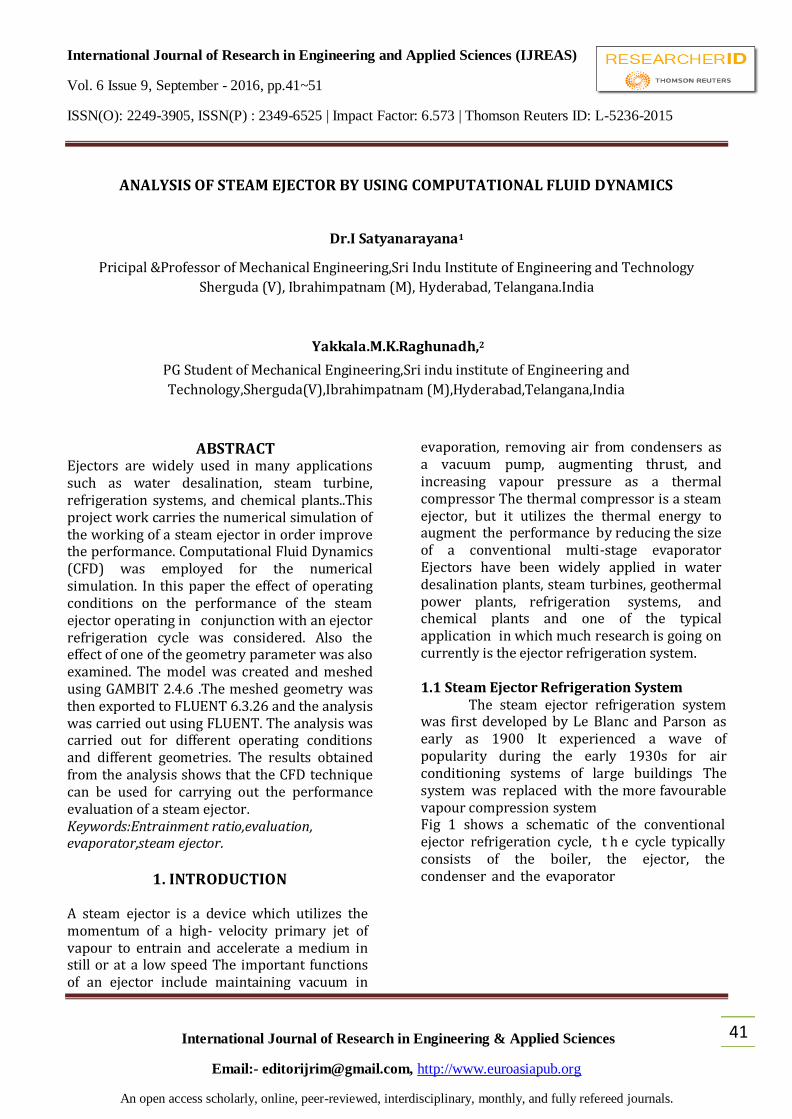
Fig 1. Schematic
diagram of a steam ejector refrigeration cycle
In figure, the liquid refrigerant boils in the boiler at a high pressure and temperature due to the application of heat This high pressure refrigerant vapour passes through line 1 and enters the primary nozzle of the ejector compressor A typical ejector cross -section with pressure and velocity profiles is shown in figure The primary stream accelerates and expands through a convergent - divergent (de Laval) nozzle to produce super- sonic flow (typical Mach number above 2), which creates a low pressure region This partial vacuum created by the supersonic primary f low entrains refrigerant vapour from the evaporator through momentum transfer in line 2 The evaporator pressure falls and boiling of the refrigerant in the evaporator occurs at a low pressure and consequently at a low temperature
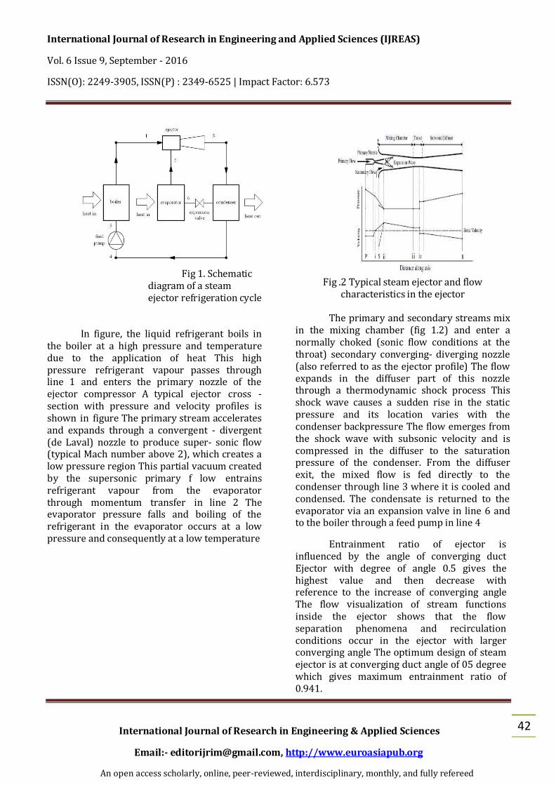
Fig .2 Typical steam ejector and flow
characteristics in the ejector
The primary and secondary streams mix in the mixing chamber (fig 1.2) and enter a normally choked (sonic flow conditions at the throat) secondary converging- diverging nozzle (also referred to as the ejector profile) The flow expands in the diffuser part of this nozzle through a thermodynamic shock process This shock wave causes a sudden rise in the static pressure and its location varies with the condenser backpressure The flow emerges from the shock wave with subsonic velocity and is compressed in the diffuser to the saturation pressure of the condenser. From the diffuser exit, the mixed flow is fed directly to the condenser through line 3 where it is cooled and condensed. The condensate is returned to the evaporator via an expansion valve in line 6 and to the boiler through a feed pump in line 4
Entrainment ratio of ejector is influenced by the angle of converging duct Ejector with degree of angle 0.5 gives the highest value and then decrease with reference to the increase of converging angle The flow visualization of stream functions inside the ejector shows that the flow separation phenomena and recirculation conditions occur in the ejector with larger converging angle The optimum design of steam ejector is at converging duct angle of 05 degree which gives maximum entrainment ratio of 0.941.
International Journal of Research in Engineering and Applied Sciences (IJREAS)
An open access scholarly, online, peer-reviewed, interdisciplinary, monthly, and fully refereed
43
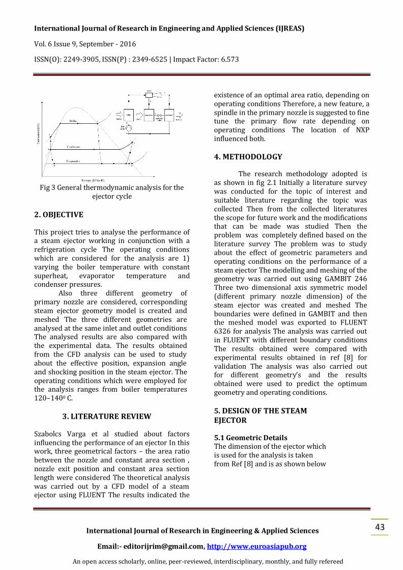
Fig 3 General thermodynamic analysis for the
ejector cycle
2. OBJECTIVE This project tries to analyse the performance of a steam ejector working in conjunction with a refrigeration cycle The operating conditions which are considered for the analysis are 1) varying the boiler temperature with constant superheat, evaporator temperature and condenser pressures. Also three different geometry of primary nozzle are considered, corresponding steam ejector geometry model is created and meshed The three different geometries are analysed at the same inlet and outlet conditions The analysed results are also compared with the experimental data. The results obtained from the CFD analysis can be used to study about the effective position, expansion angle and shocking position in the steam ejector. The operating conditions which were employed for the analysis ranges from boiler temperatures 120–1400 C.
3. LITERATURE REVIEW
Szabolcs Varga et al studied about factors influencing the performance of an ejector In this work, three geometrical factors – the area ratio between the nozzle and constant area section , nozzle exit position and constant area section length were considered The theoretical analysis was carried out by a CFD model of a steam ejector using FLUENT The results indicated the
existence of an optimal area ratio, depending on operating conditions Therefore, a new feature, a spindle in the primary nozzle is suggested to fine tune the primary flow rate depending on operating conditions The location of NXP influenced both.
4. METHODOLOGY
The research methodology adopted is as shown in fig 2.1 Initially a literature survey was conducted for the topic of interest and suitable literature regarding the topic was collected Then from the collected literatures the scope for future work and the modifications that can be made was studied Then the problem was completely defined based on the literature survey The problem was to study about the effect of geometric parameters and operating conditions on the performance of a steam ejector The modelling and meshing of the geometry was carried out using GAMBIT 246 Three two dimensional axis symmetric model (different primary nozzle dimension) of the steam ejector was created and meshed The boundaries were defined in GAMBIT and then the meshed model was exported to FLUENT 6326 for analysis The analysis was carried out in FLUENT with different boundary conditions The results obtained were compared with experimental results obtained in ref [8] for validation The analysis was also carried out for different geometry’s and the results obtained were used to predict the optimum geometry and operating conditions.
5. DESIGN OF THE STEAM EJECTOR 5.1 Geometric Details The dimension of the ejector which is used for the analysis is taken from Ref [8] and is as shown below
International Journal of Research in Engineering and Applied Sciences (IJREAS)
Table .1 Primary nozzle dimensions The other important dimensions for creating the
geometry were assumed as below. Suction inlet diameter = 492mm, Ejector outlet diameter = 40mm. Length of straight cross section after the diffuser = 20. 5.2 Constant area section length
Studies showed that the constant area section length has no effect on the entrainment ratio. Pianthong et al. indicated that the critical back pressure increases along thus allowing the ejector to operate in double chocking mode in a wide range of operating conditions. A thermodynamic shock wave occurring within the ejector geometry can cause a sudden decrease in total pressure across the shock, thus reducing the maximum pressure ratio of the constant area ejector. To overcome this shortfall, Eames et al. enhanced and developed the constant rate of momentum change method (CRMC) to achieve a diffuser geometry that removes the thermodynamic shock process through the diffuser at the designated operating conditions. The simulation results described in recent papers indicate specific improvement ratios that are achievable from an ejector designed with conventional methods. The
experimental data presented by Worall et al. also supports the theoretical findings. Vineet V. found that the variable area ejector has better performance and higher critical condenser pressure than the constant area ejector for identical boiler temperatures at an evaporator temperature of 10°C. However, the constant area ejector exhibits high performance at an evaporator temperature of 15°C.The constant area ejector performance improves by approximately 49% when the evaporator temperature increases from 10 °C to 15 °C. The steam ejector model was developed using GAMBIT 246 software Three 2-D Axi-Symmetrical model was created according to the three primary nozzle dimension specified i.e. throat diameter equal to 2mm (fig 5), is then meshed using GAMBIT and the mesh near to the wall was refined using boundary layer meshing.
Fig 5. Meshed model with throat
2mm is as shown below (first geometry)
Fig 6. Meshed model with throat
2mm enlarged view (first geometry)
6. ANALYTICAL DISCUSSIONS
The numerical analysis was designed to investigate the changing of the static pressure through the ejector axis when the parameters affecting the ejector performance were varied The operating conditions which are considered for the analysis are 1) varying the boiler
International Journal of Research in Engineering and Applied Sciences (IJREAS)
An open access scholarly, online, peer-reviewed, interdisciplinary, monthly, and fully refereed
45
temperature with constant superheat, evaporator temperature and condenser pressures; 2) varying the evaporator temperature with constant boiler temperature and condenser pressures; 3) varying the condenser pressure with constant boiler temperature and evaporator temperature Also three different geometry of primary nozzle are considered, corresponding steam ejector geometry model is created and meshed The three different geometries are analysed at the same inlet and outlet conditions The analysed results provide a better understanding in the working characteristics of a steam ejector 6.1 Static Pressure Contours Of The Steam Ejector: For Different Cases The Static pressure contour corresponding to
the boiler temperatures 120oC,130oC and
140oC
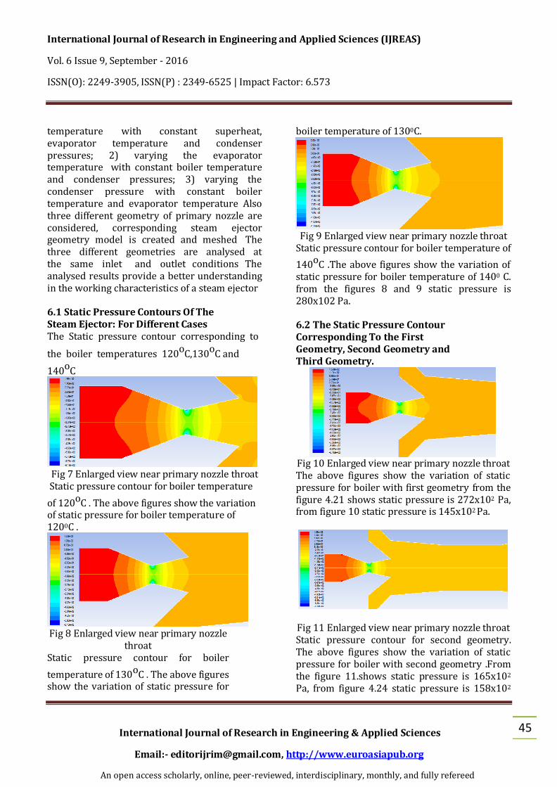
Fig 7 Enlarged view near primary nozzle throat
Static pressure contour for boiler temperature
of 120oC . The above figures show the variation of static pressure for boiler temperature of 1200C .
Fig 8 Enlarged view near primary nozzle
throat Static pressure contour for boiler
temperature of 130oC . The above figures show the variation of static pressure for
boiler temperature of 1300C.
Fig 9 Enlarged view near primary nozzle throat
Static pressure contour for boiler temperature of
140oC .The above figures show the variation of static pressure for boiler temperature of 1400 C. from the figures 8 and 9 static pressure is 280x102 Pa. 6.2 The Static Pressure Contour Corresponding To the First Geometry, Second Geometry and Third Geometry.
Fig 10 Enlarged view near primary nozzle throat The above figures show the variation of static pressure for boiler with first geometry from the figure 4.21 shows static pressure is 272x102 Pa, from figure 10 static pressure is 145x102 Pa.
Fig 11 Enlarged view near primary nozzle throat Static pressure contour for second geometry. The above figures show the variation of static pressure for boiler with second geometry .From the figure 11.shows static pressure is 165x102 Pa, from figure 4.24 static pressure is 158x102
International Journal of Research in Engineering and Applied Sciences (IJREAS)
An open access scholarly, online, peer-reviewed, interdisciplinary, monthly, and fully refereed
46
Pa.
Fig 12 Enlarged view near primary nozzle throat Static pressure contour for third geometry. The above figures show the variation of static pressure for boiler with third geometry from the figure 12 shows static pressure is 290x102 Pa, from figure 12 static pressure is 288x102 Pa. 6.3 Velocity Magnitude Contours Of The Steam Ejector For Different Cases The velocity magnitude contour for boiler
temperature 130oC, and for third geometry
(boiler temperature of 130oC; evaporator
temperature 5oC and condenser pressure 35 mbar)
Fig 13 Enlarged view near primary nozzle throat Velocity magnitude contour for boiler
temperature 130oC the above figures show the
variation of velocity magnitude for boiler
temperature of 1300C from the figure 13 shows
velocity magnitude is 101x102 m/s, from figure
13 velocity magnitude is 101x102 m/s.
Fig 14 Enlarged view near primary nozzle throat
Fig 15 Full view
Velocity magnitude contour for third geometry The above figures show the variation of velocity magnitude for boiler with third geometry from the figure 4.33 shows velocity magnitude is 137x102 m/s, from figure 15 velocity magnitude is 137x102 m/s.
7 .VALIDATION
This section gives the conformity of results obtained with the experimental results Several publications were referred to and the results given in them were taken as benchmark results for validation Intensive investigations were carried out using the range of turbulence models available in a commercial CFD code, FLUENT which solves the governing conservation equations of fluid flow by finite volume formulation It is well known that all the turbulence models currently available have their own credibility and limitations Although, very advanced models are available to close the system of equations, no model can be used for the flow prediction in all sorts of flow systems The validation fundamentally means demonstration of computational fidelity by
International Journal of Research in Engineering and Applied Sciences (IJREAS)
An open access scholarly, online, peer-reviewed, interdisciplinary, monthly, and fully refereed
47
comparing computational results to experimental data The methodology adopted for the present investigation involves comparing the predicted performance parameters and the distribution of flow parameters with the experimental results reported in literature by Kanjanapon et al Ref [8] 7.1 Effect of Operating Conditions
The variation of static pressure for the three different boiler temperature considered The level of superheat, the condenser pressure was set as 30 mbar and evaporator temperature was kept constant at 10oC for each case The values of Entrainment Ratio(ER) for the three different boiler saturation pressure cases were calculated The values are found to decrease with rise in boiler saturation pressure This is due to the reason that the lower saturation pressure resulted in a smaller mass of steam leaving the primary nozzle with less velocity This resulted in an expanded wave to fan out with smaller momentum and thus smaller expansion angle This caused a longer and larger entrained duct which resulted in the increase of entrainment ratio The variation of Mach number
of flow for the three different cases is also plotted, and is as shown in Fig. Entrainment ratio is defined as the mass flow rate ratio of secondary to primary fluid Entrainment ratio was calculated based on the stream function, according to definition of stream function the difference of two stream functions will give the amount of flow through it. This principle is used to calculate the entrainment ratio a sample calculation is given
Fig 16 Static pressure profile along ejector, effect
of boiler temperature
Fig 17 Mach number along ejector, effect of
boiler temperature Table 2 Entrainment ratio corresponding to
boiler temperatures 7.2 Effect of condenser pressure Fig 19 shows the variation of static pressure for the three different cases of condenser pressure considered The boiler temperature was set as 130oC and evaporator temperature was kept constant at 100C for each case It was seen that the change in entrainment ratio for the three cases considered were negligible It can be inferred that the entrainment ratio is not affected by the condenser pressure Another important inference from the figure below is that the shocking position moves back as the condenser pressure increases And this might cause disturbance to the mixing and entrainment process if it is further increased.
Entrainment ratio for 120oC 139
Entrainment ratio for 130oC 129
Entrainment ratio for 140oC 123
International Journal of Research in Engineering and Applied Sciences (IJREAS)
An open access scholarly, online, peer-reviewed, interdisciplinary, monthly, and fully refereed
48
Fig 19 Static pressure profile along ejector, effect
of condenser pressure
7.3 Effect of evaporator temperature Fig 20 shows the variation of static pressure for the three different cases of evaporator temperature considered The boiler temperature was set as 130oC and condenser pressure was kept constant at 40mbar for each case It was seen that the entrainment ratio increases with increase in evaporator temperature This is due to the movement of effective position to downstream with an increasingly higher evaporator temperature The resultant longer entrained duct can handle higher amounts of secondary fluid which increases the entrainment and coefficient of performance of the refrigeration.
Fig 20 Static pressure profile along ejector, effect
of evaporator temperature Table 3 Entrainment ratio for different
evaporator temperature
Entrainment ratio for 5oC 098
Entrainment ratio for 10oC 112
Entrainment ratio for 15oC 127
7.3 Effect of Steam Ejector Geometry The primary nozzle dimension was varied and the steam ejector performance was
studied at boiler temperature of 130oC,
evaporator temperature of 5oC and at a condenser pressure of 35 mbar Fig shows the variation of static pressure along the steam ejector The entrainment ratio was calculated and it was found that the entrainment ratio increases as the throat diameter was reduced When a smaller primary nozzle was used, smaller amount of primary mass expanded through the primary nozzle The enlargement of the entrained duct can be investigated from the moving downstream of the effective position
Fig 21 Static pressure profile along ejector, effect
of primary nozzle throat diameter Table 4 Entrainment ratio for first, second and third geometry
Table: 4.Ratio of geometry
7.4 Entrainment Ratio Sample Calculation The primary and secondary mass flow rates are calculated from the values obtained from the figure as given below
Entrainment ratio for first geometry
107
Entrainment ratio for second geometry
138
Entrainment ratio for third geometry
160
International Journal of Research in Engineering and Applied Sciences (IJREAS)
An open access scholarly, online, peer-reviewed, interdisciplinary, monthly, and fully refereed
49
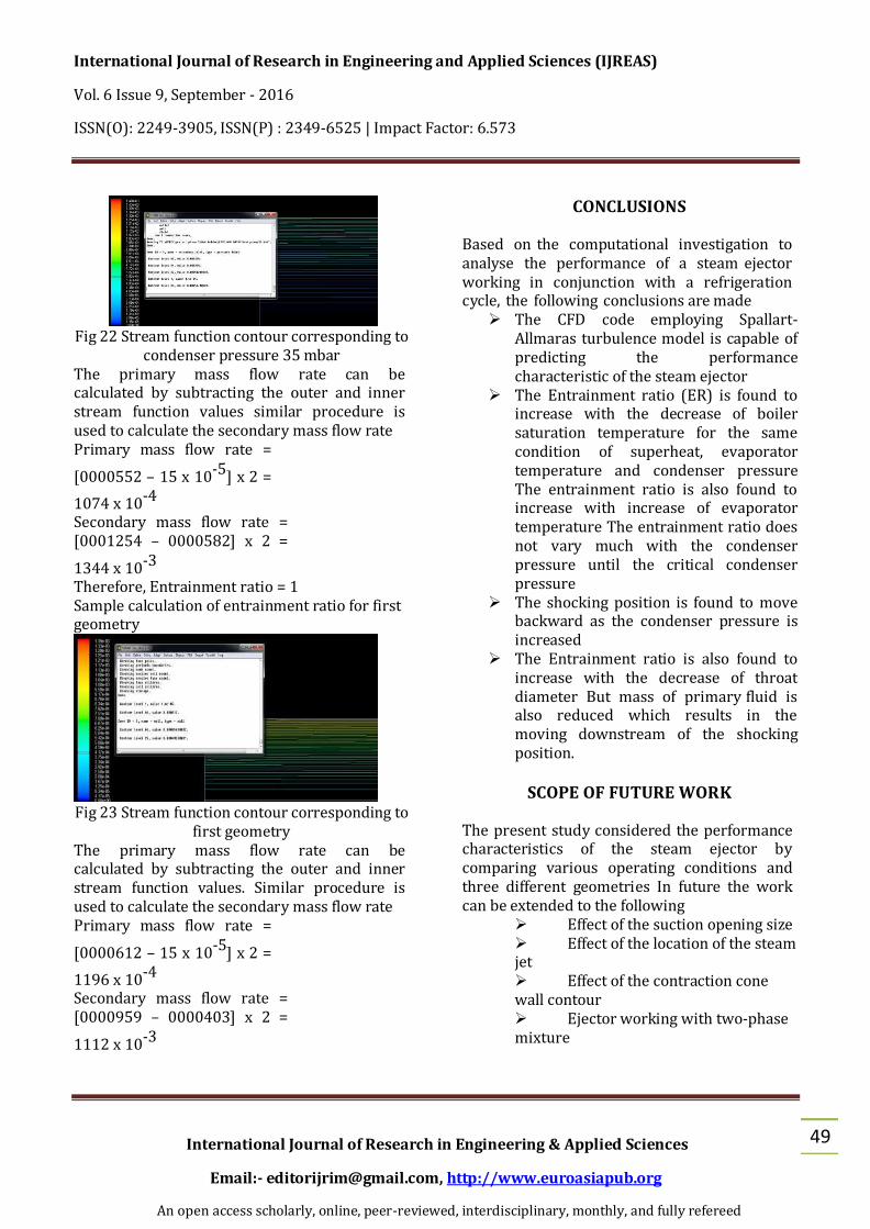
Fig 22 Stream function contour corresponding to
condenser pressure 35 mbar The primary mass flow rate can be calculated by subtracting the outer and inner stream function values similar procedure is used to calculate the secondary mass flow rate Primary mass flow rate =
[0000552 – 15 x 10-5] x 2 =
1074 x 10-4 Secondary mass flow rate = [0001254 – 0000582] x 2 =
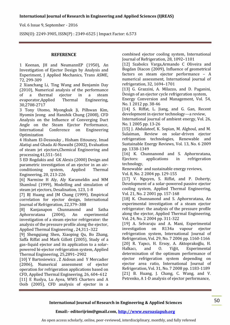
1344 x 10-3 Therefore, Entrainment ratio = 1 Sample calculation of entrainment ratio for first geometry
Fig 23 Stream function contour corresponding to
first geometry The primary mass flow rate can be calculated by subtracting the outer and inner stream function values. Similar procedure is used to calculate the secondary mass flow rate Primary mass flow rate =
[0000612 – 15 x 10-5] x 2 =
1196 x 10-4 Secondary mass flow rate = [0000959 – 0000403] x 2 =
1112 x 10-3
CONCLUSIONS
Based on the computational investigation to analyse the performance of a steam ejector working in conjunction with a refrigeration cycle, the following conclusions are made
The CFD code employing Spallart-Allmaras turbulence model is capable of predicting the performance characteristic of the steam ejector
The Entrainment ratio (ER) is found to increase with the decrease of boiler saturation temperature for the same condition of superheat, evaporator temperature and condenser pressure The entrainment ratio is also found to increase with increase of evaporator temperature The entrainment ratio does not vary much with the condenser pressure until the critical condenser pressure
The shocking position is found to move backward as the condenser pressure is increased
The Entrainment ratio is also found to increase with the decrease of throat diameter But mass of primary fluid is also reduced which results in the moving downstream of the shocking position.
SCOPE OF FUTURE WORK
The present study considered the performance characteristics of the steam ejector by comparing various operating conditions and three different geometries In future the work can be extended to the following
Effect of the suction opening size Effect of the location of the steam jet Effect of the contraction cone wall contour Ejector working with two-phase mixture
International Journal of Research in Engineering and Applied Sciences (IJREAS)
An open access scholarly, online, peer-reviewed, interdisciplinary, monthly, and fully refereed
50
REFERENCE
1 Keenan, JH and NeumannEP (1950), An Investigation of Ejector Design by Analysis and Experiment, J Applied Mechanics, Trans ASME, 72, 299-309 2 Xianchang Li, Ting Wang and Benjamin Day (2010), Numerical analysis of the performance of a thermal ejector in a steam evaporator,Applied Thermal Engineering, 30,2708-2717 3 Tony Utomo, Myongkuk Ji, Pilhwan Kim, Hyomin Jeong and Hanshik Chung (2008), CFD Analysis on the Influence of Converging Duct Angle on the Steam Ejector Performance, International Conference on Engineering Optimization 4 Hisham El-Dessouky , Hisham Ettouney, Imad Alatiqi and Ghada Al-Nuwaibi (2002), Evaluation of steam jet ejectors,Chemical Engineering and processing,41,551–561 5 ED Rogdakis and GK Alexis (2000) Design and parametric investigation of an ejector in an air-conditioning system, Applied Thermal Engineering, 20, 213-226 [6] Narmine H Aly, Aly Karameldin and MM Shamloul (1999), Modelling and simulation of steam jet ejectors, Desalination, 123, 1-8 [7] BJ Huang and JM Chang (1999), Empirical correlation for ejector design, International Journal of Refrigeration, 22,379–388 [8] Kanjanapon Chunnanond and Satha Aphornratana (2004), An experimental investigation of a steam ejector refrigerator: the analysis of the pressure profile along the ejector, Applied Thermal Engineering , 24,311–322 [9] Shengqiang Shen, Xiaoping Qu, Bo Zhang, Saffa Riffat and Mark Gillott (2005), Study of a gas–liquid ejector and its application to a solar-powered bi-ejector refrigeration system, Applied Thermal Engineering, 25,2891–2902 [10] Y Bartosiewicz , Z Aidoun and Y Mercadier (2006), Numerical assessment of ejector operation for refrigeration applications based on CFD, Applied Thermal Engineering, 26, 604–612 [11] E Ruslya, Lu Ayea, WWS Charters and A Ooib (2005), CFD analysis of ejector in a
combined ejector cooling system, International Journal of Refrigeration, 28, 1092–1101 [12] Szabolcs Varga,Armando C Oliveira and Bogdan Diacon (2009), Influence of geometrical factors on steam ejector performance – A numerical assessment, International journal of refrigeration, 32, 1694–1701 [13] G. Grazzini, A. Milazzo, and D. Paganini, Design of an ejector cycle refrigeration system, Energy Conversion and Management, Vol. 54, No. 1 2012 pp. 38-46 [14] S. Riffat, L. Jiang, and G. Gan, Recent development in ejector technology—a review, International journal of ambient energy, Vol. 26, No. 1 2005 pp. 13-26 [15] J. Abdulateef, K. Sopian, M. Alghoul, and M. Sulaiman, Review on solar-driven ejector refrigeration technologies, Renewable and Sustainable Energy Reviews, Vol. 13, No. 6 2009 pp. 1338-1349 [16] K. Chunnanond and S. Aphornratana, Ejectors: applications in refrigeration technology, Renewable and sustainable energy reviews, Vol. 8, No. 2 2004 pp. 129-155 [17] V. Nguyen, S. Riffat, and P. Doherty, Development of a solar-powered passive ejector cooling system, Applied Thermal Engineering, Vol. 21, No. 2 2001 pp. 157-168 [18] K. Chunnanond and S. Aphornratana, An experimental investigation of a steam ejector refrigerator: the analysis of the pressure profile along the ejector, Applied Thermal Engineering, Vol. 24, No. 2 2004 pp. 311-322 [19] A. Selvaraju and A. Mani, Experimental investigation on R134a vapour ejector refrigeration system, International Journal of Refrigeration, Vol. 29, No. 7 2006 pp. 1160-1166 [20] R. Yapıcı, H. Ersoy, A. Aktoprakoğlu, H. Halkacı, and O. Yiğit, Experimental determination of the optimum performance of ejector refrigeration system depending on ejector area ratio, International Journal of Refrigeration, Vol. 31, No. 7 2008 pp. 1183-1189 [21] B. Huang, J. Chang, C. Wang, and V. Petrenko, A 1-D analysis of ejector performance,
International Journal of Research in Engineering and Applied Sciences (IJREAS)