1 Analysis of the electromagnetic acoustic noise and vibrations of a high-speed brushless DC motor J. Le Besnerais*, Q. Souron*, E. Devillers** *EOMYS ENGINEERING, www.eomys.com ** L2EP, Ecole Centrale Lille, France Keywords: magnetic forces, vibration, acoustic noise, BLDC, PMSM, high-speed Abstract In this paper, the acoustic noise and vibrations due to Maxwell forces of a 4-pole, 12-slot, high-speed brushless DC motor (BLDC) is analysed up to 90 kRPM. The harmonic magnetic forces present in the machine are first analytically characterized, and validated with numerical simulations using MANATEE ® electromagnetic and vibro-acoustic software. The effects of rotor vibrations due to bearing faults, pole displacements and eccentricities are considered. Finally, some complete experimental measurements relying on “spatiogram” techniques are run to characterize the vibration waves (wavenumber and frequency) involved in acoustic noise generation. These results are compared to simulations and it is demonstrated that the observed high acoustic noise is due to machine imperfections creating harmonic forces exciting the bending mode of the shaft and the stator elliptical mode. Nomenclature Symbol Description fR mechanical frequency [Hz] fs electrical frequency [Hz] p pole pair number Zs stator slot number 1 Introduction 1.1 Magnetic noise and vibrations The vibro-acoustic design of electrical machines can be as important as its electromagnetic or thermal design in an increasing number of applications. This is the case of rotating machines working close to human presence in industrial applications (e.g. high power pumps), household appliances (e.g. electric curtains) and transportation applications (e.g. electric motors in ships, trains and cars). The use of vibro- acoustic models along with electro-mechanic models allows to estimate acoustic noise and vibration levels at design stage, avoiding costly remanufacturing or acoustic insulation of noisy machines. Once the electrical machine is manufactured, some advanced experimental methods allows to understand the noise and vibration generation process, identify its sources and reduce them with passive or active methods. The noise and vibration sources of electrical machines are usually classified in three distinct types: mechanical, aerodynamic and electromagnetic sources. Mechanical noise and vibrations can come from ball bearings, eccentricities, gears and brush commutators, whereas aerodynamic noise is due to air pressure periodic variations coming for instance from fans or air-gap vortices. Audible electromagnetic noise is due to the vibrations of some magnetic parts of the electrical machine submitted to magnetic excitation fields, which can be permanent sources as in permanent magnet synchronous machines, or induced by some current sources as in induction machines; these vibrations, called “magnetic vibrations” as they are due to magnetic forces, can be responsible for direct air-borne noise (e.g. through stator and frame vibration) or structural-borne noise (e.g. propagation of rotor vibrations due to magnetic pull through bearings and frame). The electromagnetic noise can dominate the global sound power level, as it is characterized by strong specific tonalities (emergence of a given harmonic above the background noise) in the most sensitive frequencies of the human ear, which make them sound particularly unpleasant. 1.2 Vibro-acoustics of high-speed BLDC Permanent magnet brushless machines having rotational speeds up to 100 krpm have first emerged in applications such as vacuum pumps and compressors. It then found new applications like spindles for machine tools and micro turbines [11]. Since the 1990s a lot of work has been carried on the analysis of the root cause of BLDC machines magnetic vibrations, and more generally permanent magnet (PM) machines. In [13][15][1][3] some analytical analysis is developed to characterize Maxwell magnetic forces harmonics in terms of spatial and time frequency orders, in no-load case and in loaded case including armature-field reaction. The effect of static and dynamic eccentricity is for instance investigated in [14] and [16], whereas the effect of magnet magnetization shape on vibration is studied in [18]. Besides radial and tangential airgap reluctant forces, some other phenomena can generate magnetic vibrations and acoustic noise. In [8] it is shown for example that the asymmetrical magnet overhang of a BLDC can generate an
Transcript
1
Analysis of the electromagnetic acoustic noise and vibrations of a high-speed brushless DC motor
J. Le Besnerais*, Q. Souron*, E. Devillers**
*EOMYS ENGINEERING, www.eomys.com ** L2EP, Ecole Centrale Lille, France
Keywords: magnetic forces, vibration, acoustic noise, BLDC, PMSM, high-speed
Abstract
In this paper, the acoustic noise and vibrations due to Maxwell forces of a 4-pole, 12-slot, high-speed brushless DC motor (BLDC) is analysed up to 90 kRPM. The harmonic magnetic forces present in the machine are first analytically characterized, and validated with numerical simulations using MANATEE® electromagnetic and vibro-acoustic software. The effects of rotor vibrations due to bearing faults, pole displacements and eccentricities are considered. Finally, some complete experimental measurements relying on “spatiogram” techniques are run to characterize the vibration waves (wavenumber and frequency) involved in acoustic noise generation. These results are compared to simulations and it is demonstrated that the observed high acoustic noise is due to machine imperfections creating harmonic forces exciting the bending mode of the shaft and the stator elliptical mode.
Nomenclature
Symbol Description fR mechanical frequency [Hz] fs electrical frequency [Hz] p pole pair number Zs stator slot number
1 Introduction
1.1 Magnetic noise and vibrations The vibro-acoustic design of electrical machines can be as important as its electromagnetic or thermal design in an increasing number of applications. This is the case of rotating machines working close to human presence in industrial applications (e.g. high power pumps), household appliances (e.g. electric curtains) and transportation applications (e.g. electric motors in ships, trains and cars). The use of vibro-acoustic models along with electro-mechanic models allows to estimate acoustic noise and vibration levels at design stage, avoiding costly remanufacturing or acoustic insulation of noisy machines. Once the electrical machine is manufactured, some
advanced experimental methods allows to understand the noise and vibration generation process, identify its sources and reduce them with passive or active methods. The noise and vibration sources of electrical machines are usually classified in three distinct types: mechanical, aerodynamic and electromagnetic sources. Mechanical noise and vibrations can come from ball bearings, eccentricities, gears and brush commutators, whereas aerodynamic noise is due to air pressure periodic variations coming for instance from fans or air-gap vortices. Audible electromagnetic noise is due to the vibrations of some magnetic parts of the electrical machine submitted to magnetic excitation fields, which can be permanent sources as in permanent magnet synchronous machines, or induced by some current sources as in induction machines; these vibrations, called “magnetic vibrations” as they are due to magnetic forces, can be responsible for direct air-borne noise (e.g. through stator and frame vibration) or structural-borne noise (e.g. propagation of rotor vibrations due to magnetic pull through bearings and frame). The electromagnetic noise can dominate the global sound power level, as it is characterized by strong specific tonalities (emergence of a given harmonic above the background noise) in the most sensitive frequencies of the human ear, which make them sound particularly unpleasant. 1.2 Vibro-acoustics of high-speed BLDC Permanent magnet brushless machines having rotational speeds up to 100 krpm have first emerged in applications such as vacuum pumps and compressors. It then found new applications like spindles for machine tools and micro turbines [11]. Since the 1990s a lot of work has been carried on the analysis of the root cause of BLDC machines magnetic vibrations, and more generally permanent magnet (PM) machines. In [13][15][1][3] some analytical analysis is developed to characterize Maxwell magnetic forces harmonics in terms of spatial and time frequency orders, in no-load case and in loaded case including armature-field reaction. The effect of static and dynamic eccentricity is for instance investigated in [14] and [16], whereas the effect of magnet magnetization shape on vibration is studied in [18]. Besides radial and tangential airgap reluctant forces, some other phenomena can generate magnetic vibrations and acoustic noise. In [8] it is shown for example that the asymmetrical magnet overhang of a BLDC can generate an
2
axial magnetic thrust responsible for additional magnetic vibrations and noise. The asymmetries of the stator magnetic circuit can also create additional vibration and noise [19]. However, little work has been carried on high speed applications. The vibro-acoustic behaviour of high speed machines is more challenging as the largest magnetic reluctance forces, which are due to the fundamental field and occur at twice the electrical frequency, can more easily meet one of the stator or rotor natural frequency. The high speed operation also increases the frequency range of exciting forces at variable speed, increasing the risk of resonances and acoustic tonalities. In [12] the vibration behaviour of high speed BLDC rotor is discussed; it is shown that the rotor bending mode natural frequency resonance with magnetic forces can lead to serious damage of the machine, and some calculation models of the rotor natural frequencies are presented and validated. [20] also studies the vibration behaviour of high-speed PMSM under mechanical unbalance. In this paper, a BLDC operating up to 90 krpm is analysed using both experimental advanced measurements and numerical simulations with MANATEE software [5]. The sources of vibrations are analysed and it is shown that the asymmetrical pole position is responsible for the excitation of the stator elliptical mode. The rotor bending mode is also excited due to asymmetrical pole position or dynamic eccentricity. 1.3 Machine characteristics The studied machine is a BLDC motor with surface inset permanent magnets for small scale electrical race cars with the following characteristics:
Number of pole pairs p 2 Number of stator teeth Zs 12 Stator outer diameter [mm] 34 Stack length [mm] 15
A cylindrical frame is shrink fit to the stator lamination. The frame holds two ball bearings for the rotor shaft. The stator winding is a double layer concentrated winding. The eccentricities could not be measured, nor the stator lamination roundness. The position of the poles have been measured and are unevenly distributed as shown in Figure 1.
Figure 1: Rotor poles and interpoles angular width of studied
BLDC
Neither the stator nor the rotor is skewed.
2 Theoretical analysis
2.1 Characterization of magnetic forces The machine is very short so longitudinal modes of the lamination do not play an important vibro-acoustic role. Besides that, there is no skew: neglecting end effects, magnetic forces do not vary along the axial direction of the machine. The Maxwell stress tensor can therefore be Fourier-developed along the airgap circumference and characterized by an infinite sum of stress waves of frequency f and wavenumber r. At no-load, the lowest non-zero wavenumber of magnetic forces is given by � = ���(2�, �)=4 ([1], [2]) at f=2fs. These radial and tangential harmonic forces are due to the magnet magnetomotive force and slot permeance interactions: � = 4
�� �� �� �� � (0, 0) (�, ��) (0, 0) (�, ��) 2�� (0, 0) (3�, 3��) (0, 0) (�, ��) 2�� (� , 0) (�, ��) (−� , 0) (�, ��) 2�� (2�, 0) (�, ��) (−2�, 0) (�, ��) 2�� (0, 0) (�, ��) (−� , 0) (5�, 5��) −4�� (−� , 0) (3�, 3��) (−� , 0) (�, ��) 2�� (0, 0) (7�, 7��) (−� , 0) (�, ��) 8�� (0, 0) (5�, 5��) (0, 0) (3�, 3��) 2�� This table is an automated analysis of the spectral content of magnetic forces coming from MANATEE software [5]. The notation (r,f) is use to identify a permeance or mmf wave of wavenumber r and electrical frequency f. The force waves are sorted by decreasing magnitude. Radial and tangential force waves of wavenumber � = 0 occur at multiples of ���(2�, �)=12 the rotational frequency, so multiples of 6fs [1]. The following table identifies the origin of stator reluctance and rotor field harmonics giving rise to these types of harmonics forces: � = 0
[17]. As the current waveform contains odd frequencies, the resulting magnetic forces have only even frequencies at 2fs, 4fs, 6fs, etc. However, only no-load operation is considered in this paper. 2.2 Characterization of mechanical forces In normal operating conditions, a ball bearing is a source of friction forces at the mechanical frequency �� and its multiples. Let � , ! , �, ", !# and , !$ respectively be the number of rolling elements, the ball diameter, the pitch diameter, the contact angle of rolling elements, the diameter of the inner contact surface and the diameter of the outer contact surface. If bearing faults are present, fundamental vibration frequencies of the bearing are [4]:
• Outer and inner rolling pass of the balls (with simplified formula): �#� = 0.6� �� = 4.2�� �$� = 0.4� �� = 2.8��
• Rolling ball frequency:
� � = �2! �� &1 − '! � (� )*+�("), = 2.78��
• Frequency linked to irregularities in the ball cage
� - = ��!#!# + !$ = 0.36��
• Frequency due to variation of the bearing stiffness
��/ = � !#!# + !$ �� = 2.53��
Experimental work of §4 shows that some modulation at 0.37fr is present, so that the studied BLDC has some irregularities in the ball cage.
3 Numerical analysis
3.1 Introduction To confirm the theoretical and experimental analysis, some electromagnetic and vibro-acoustic numerical calculations are run with MANATEE® simulation software at variable speed [5]. Due to the high-speed operation of the machine, some significant acoustic noise occurs up to 10 kHz which makes it difficult to use finite element methods. The semi-analytical models of MANATEE are therefore used: the electromagnetic model is based on subdomain modelling techniques, and the vibro-acoustic model is based on analytical techniques. Each simulation run takes only a few seconds to calculate magnetically induced vibration and noise levels from 5 to 65 krpm up to 20 kHz. In this paper, all simulations are carried at no-load. 3.2 Ideal case A first simulation is run assuming
• no dynamic nor static eccentricity ; • even spacing of the poles and uniform
magnetization; • no modulation of the airgap width due to rotor
vibration.
The radial force spectrograms represent the Maxwell radial harmonics as a function of wavenumbers and rotation speed.
Figure 2: radial force harmonics spectrograms in the ideal
case (no imperfections) for wavenumbers r=0 and r=4 In the ideal case the following force and vibration harmonics are therefore present:
which confirms the theory presented in §2.1. The radial vibration spectrogram is given by:
4
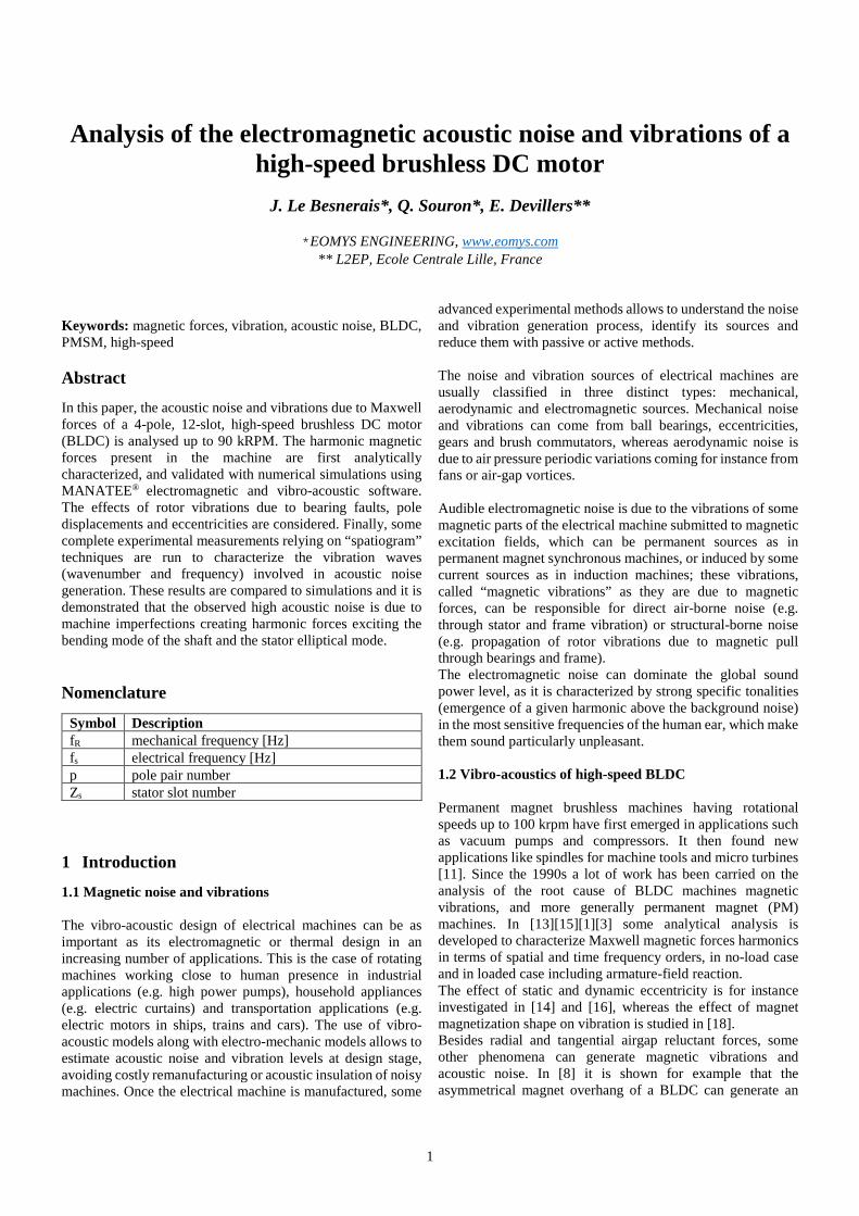
Figure 3: radial acceleration spectrogram in ideal case (no
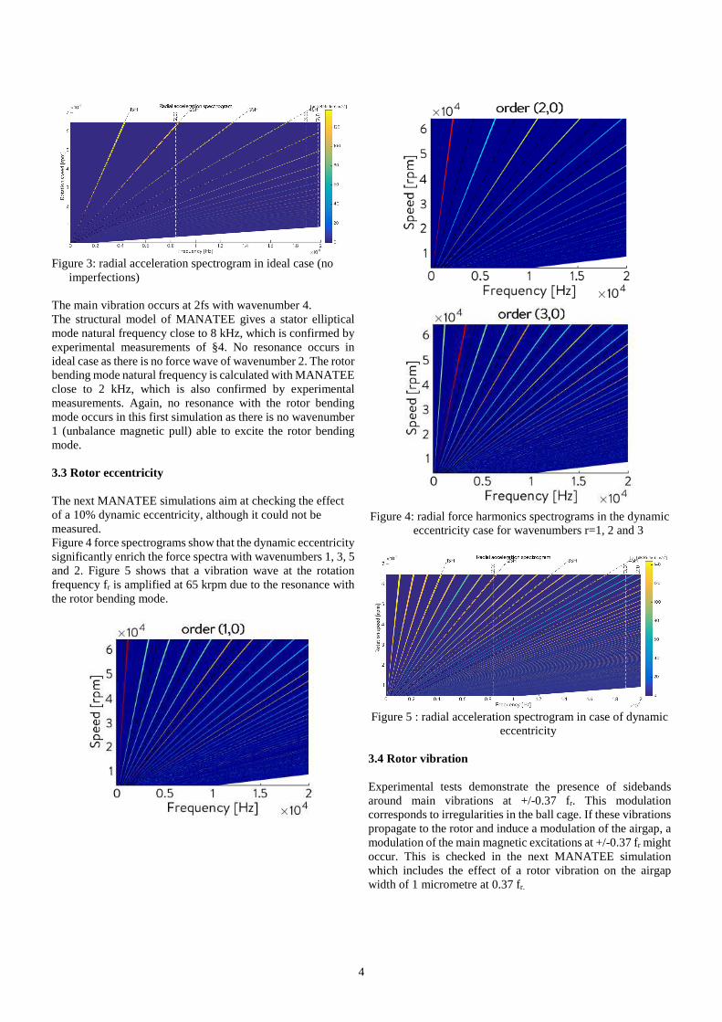
imperfections) The main vibration occurs at 2fs with wavenumber 4. The structural model of MANATEE gives a stator elliptical mode natural frequency close to 8 kHz, which is confirmed by experimental measurements of §4. No resonance occurs in ideal case as there is no force wave of wavenumber 2. The rotor bending mode natural frequency is calculated with MANATEE close to 2 kHz, which is also confirmed by experimental measurements. Again, no resonance with the rotor bending mode occurs in this first simulation as there is no wavenumber 1 (unbalance magnetic pull) able to excite the rotor bending mode. 3.3 Rotor eccentricity The next MANATEE simulations aim at checking the effect of a 10% dynamic eccentricity, although it could not be measured. Figure 4 force spectrograms show that the dynamic eccentricity significantly enrich the force spectra with wavenumbers 1, 3, 5 and 2. Figure 5 shows that a vibration wave at the rotation frequency fr is amplified at 65 krpm due to the resonance with the rotor bending mode.
Figure 4: radial force harmonics spectrograms in the dynamic
eccentricity case for wavenumbers r=1, 2 and 3
Figure 5 : radial acceleration spectrogram in case of dynamic
eccentricity
3.4 Rotor vibration Experimental tests demonstrate the presence of sidebands around main vibrations at +/-0.37 fr. This modulation corresponds to irregularities in the ball cage. If these vibrations propagate to the rotor and induce a modulation of the airgap, a modulation of the main magnetic excitations at +/-0.37 fr might occur. This is checked in the next MANATEE simulation which includes the effect of a rotor vibration on the airgap width of 1 micrometre at 0.37 fr.
5
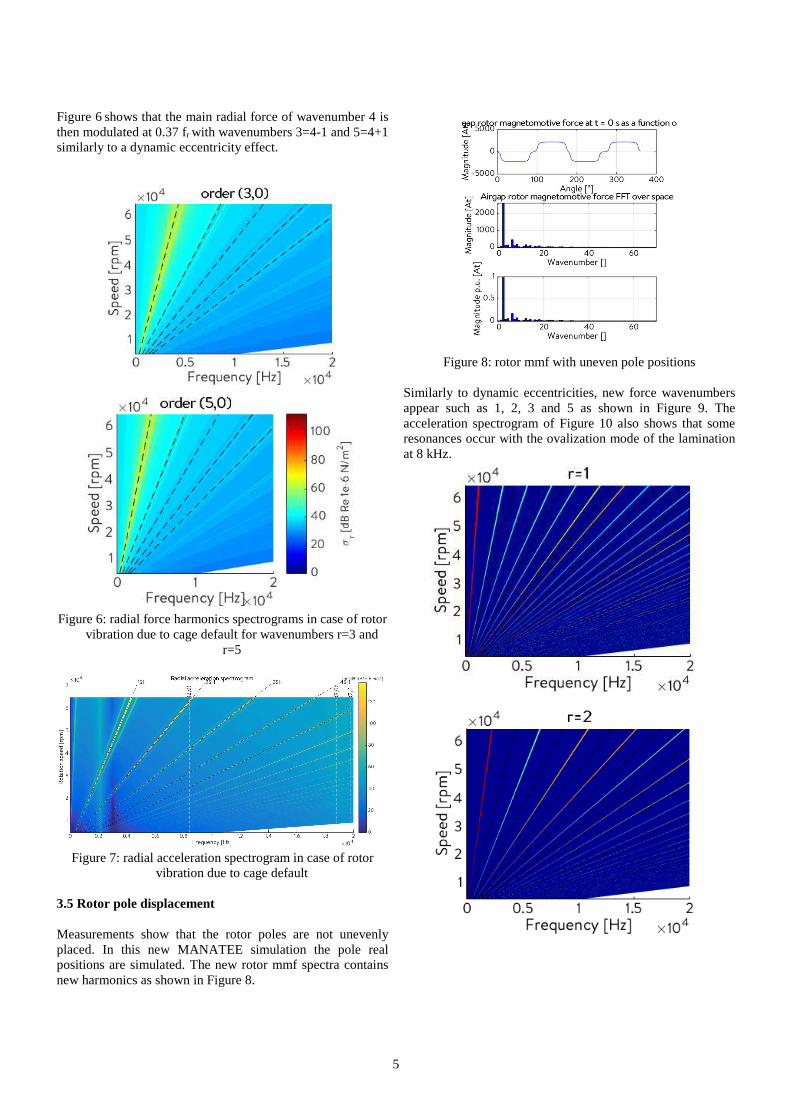
Figure 6 shows that the main radial force of wavenumber 4 is then modulated at 0.37 fr with wavenumbers 3=4-1 and 5=4+1 similarly to a dynamic eccentricity effect.
Figure 6: radial force harmonics spectrograms in case of rotor
vibration due to cage default for wavenumbers r=3 and r=5
Figure 7: radial acceleration spectrogram in case of rotor
vibration due to cage default 3.5 Rotor pole displacement Measurements show that the rotor poles are not unevenly placed. In this new MANATEE simulation the pole real positions are simulated. The new rotor mmf spectra contains new harmonics as shown in Figure 8.
Figure 8: rotor mmf with uneven pole positions
Similarly to dynamic eccentricities, new force wavenumbers appear such as 1, 2, 3 and 5 as shown in Figure 9. The acceleration spectrogram of Figure 10 also shows that some resonances occur with the ovalization mode of the lamination at 8 kHz.
6
Figure 9 : radial force harmonics spectrograms in case of
asymmetrical pole positions for wavenumbers r=1, 2, 3 and r=5
Figure 10: radial acceleration spectrogram in case of unevenly
spaced rotor poles 3.6 Real case The last simulation combines all previous faults. The spectrogram of Figure 11 shows that two main resonances occur with the first rotor bending mode and the stator ovalization mode.
Figure 11 : radial acceleration spectrogram for the “real”
design including all imperfections
4 Experimental analysis
In this part, the BLDC is equipped with 8 accelerometers, a microphone and a tachometer. Some no-load run-ups are carried and several advanced post-processings are done to identify the vibration waves responsible for acoustic noise as order tracking analysis, operational deflection shapes (ODS), and “spatiograms” ([6], [7]).
4.1 Experimental set-up
In order to analyse the vibration behaviour of the high-speed brushless DC, 8 miniature accelerometers (B&K type 4517) are equally spaced along the circumference of the machine as shown on Figure 12.
Figure 12: Experimental set-up with 8 miniature accelerometers around the BLDC circumference
Those accelerometers measure radial acceleration of the machine. A tachometer (B&K Laser tacho probe Type 2981) and a microphone (PCB Model 377B02, located at 9cm of the source) are also used for the measurement.
7
4.2 Vibro-acoustic behaviour
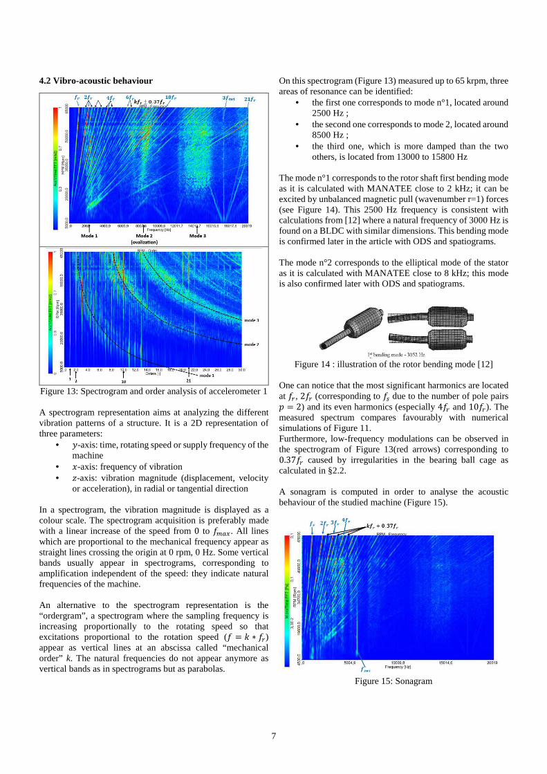
Figure 13: Spectrogram and order analysis of accelerometer 1 A spectrogram representation aims at analyzing the different vibration patterns of a structure. It is a 2D representation of three parameters:
• 0-axis: time, rotating speed or supply frequency of the machine
• 1-axis: frequency of vibration • 2-axis: vibration magnitude (displacement, velocity
or acceleration), in radial or tangential direction In a spectrogram, the vibration magnitude is displayed as a colour scale. The spectrogram acquisition is preferably made with a linear increase of the speed from 0 to �345. All lines which are proportional to the mechanical frequency appear as straight lines crossing the origin at 0 rpm, 0 Hz. Some vertical bands usually appear in spectrograms, corresponding to amplification independent of the speed: they indicate natural frequencies of the machine. An alternative to the spectrogram representation is the “ordergram”, a spectrogram where the sampling frequency is increasing proportionally to the rotating speed so that excitations proportional to the rotation speed (� = 6 ∗ ��) appear as vertical lines at an abscissa called “mechanical order” k. The natural frequencies do not appear anymore as vertical bands as in spectrograms but as parabolas.
On this spectrogram (Figure 13) measured up to 65 krpm, three areas of resonance can be identified:
• the first one corresponds to mode n°1, located around 2500 Hz ;
• the second one corresponds to mode 2, located around 8500 Hz ;
• the third one, which is more damped than the two others, is located from 13000 to 15800 Hz
The mode n°1 corresponds to the rotor shaft first bending mode as it is calculated with MANATEE close to 2 kHz; it can be excited by unbalanced magnetic pull (wavenumber r=1) forces (see Figure 14). This 2500 Hz frequency is consistent with calculations from [12] where a natural frequency of 3000 Hz is found on a BLDC with similar dimensions. This bending mode is confirmed later in the article with ODS and spatiograms. The mode n°2 corresponds to the elliptical mode of the stator as it is calculated with MANATEE close to 8 kHz; this mode is also confirmed later with ODS and spatiograms.
Figure 14 : illustration of the rotor bending mode [12]
One can notice that the most significant harmonics are located at ��, 2�� (corresponding to �� due to the number of pole pairs � = 2) and its even harmonics (especially 4�� and 10��). The measured spectrum compares favourably with numerical simulations of Figure 11. Furthermore, low-frequency modulations can be observed in the spectrogram of Figure 13(red arrows) corresponding to 0.37�� caused by irregularities in the bearing ball cage as calculated in §2.2. A sonagram is computed in order to analyse the acoustic behaviour of the studied machine (Figure 15).
Figure 15: Sonagram
8
The most important harmonics occur at multiple of the mechanical frequency ��. In addition, modulations at 0.37�� could also be seen, as already mentioned for the acceleration analysis.
4.3 Spatiogram and ODS
The spatiogram aims at introducing a space information besides the time and frequency information of the usual spectrogram. This is done by mounting a series of accelerometers around the stator circumference, and making a two-dimensional Discrete Fourier Transform of the acceleration. The result is a “spatial filter” of a usual spectrogram. As in time domain, the maximum wavenumber
that can be captured by �4-- accelerometers is � = 89::� , due to
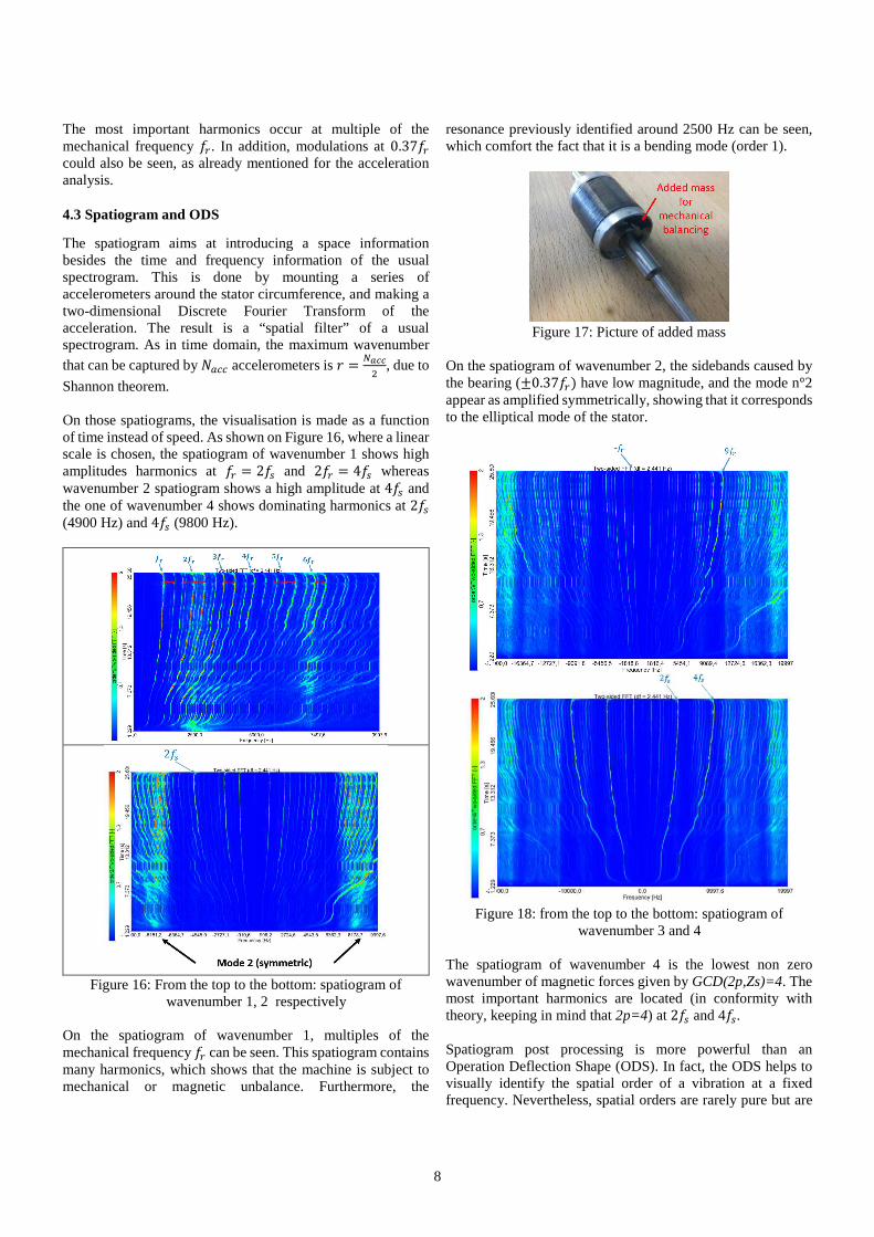
Shannon theorem. On those spatiograms, the visualisation is made as a function of time instead of speed. As shown on Figure 16, where a linear scale is chosen, the spatiogram of wavenumber 1 shows high amplitudes harmonics at �� = 2�� and 2�� = 4�� whereas wavenumber 2 spatiogram shows a high amplitude at 4�� and the one of wavenumber 4 shows dominating harmonics at 2�� (4900 Hz) and 4�� (9800 Hz).
Figure 16: From the top to the bottom: spatiogram of
wavenumber 1, 2 respectively On the spatiogram of wavenumber 1, multiples of the mechanical frequency �� can be seen. This spatiogram contains many harmonics, which shows that the machine is subject to mechanical or magnetic unbalance. Furthermore, the
resonance previously identified around 2500 Hz can be seen, which comfort the fact that it is a bending mode (order 1).
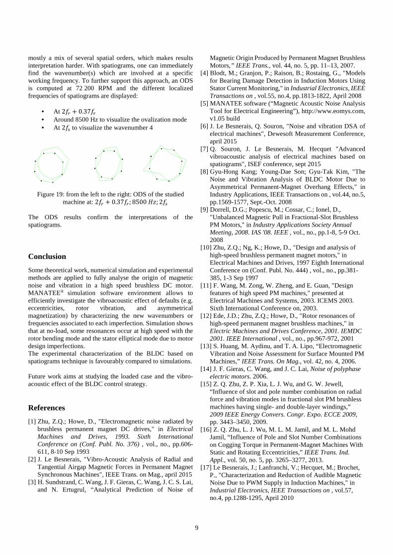
Figure 17: Picture of added mass
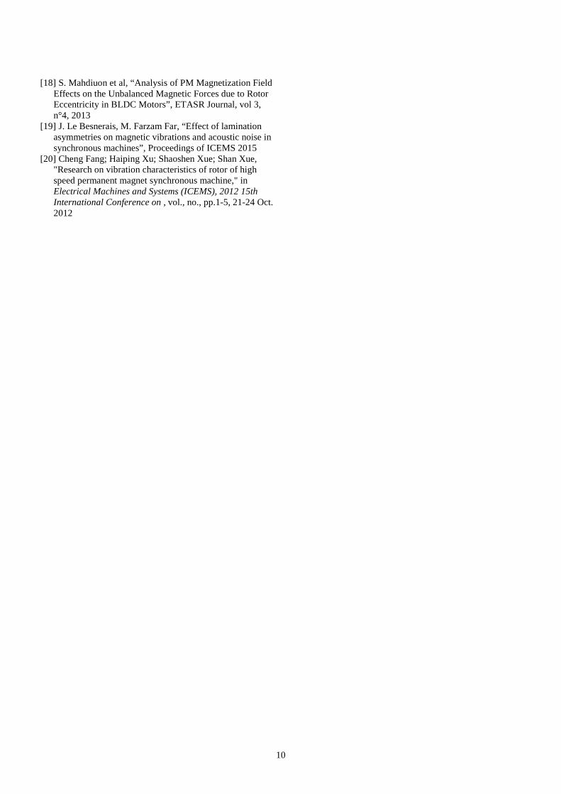
On the spatiogram of wavenumber 2, the sidebands caused by the bearing (±0.37��) have low magnitude, and the mode n°2 appear as amplified symmetrically, showing that it corresponds to the elliptical mode of the stator.
Figure 18: from the top to the bottom: spatiogram of
wavenumber 3 and 4 The spatiogram of wavenumber 4 is the lowest non zero wavenumber of magnetic forces given by GCD(2p,Zs)=4. The most important harmonics are located (in conformity with theory, keeping in mind that 2p=4) at 2�� and 4��. Spatiogram post processing is more powerful than an Operation Deflection Shape (ODS). In fact, the ODS helps to visually identify the spatial order of a vibration at a fixed frequency. Nevertheless, spatial orders are rarely pure but are
9
mostly a mix of several spatial orders, which makes results interpretation harder. With spatiograms, one can immediately find the wavenumber(s) which are involved at a specific working frequency. To further support this approach, an ODS is computed at 72 200 RPM and the different localized frequencies of spatiograms are displayed:
• At 2�� + 0.37�� • Around 8500 Hz to visualize the ovalization mode • At 2�� to visualize the wavenumber 4
Figure 19: from the left to the right: ODS of the studied
machine at: 2�� + 0.37��; 8500 =2; 2�� The ODS results confirm the interpretations of the spatiograms.
Conclusion
Some theoretical work, numerical simulation and experimental methods are applied to fully analyse the origin of magnetic noise and vibration in a high speed brushless DC motor. MANATEE® simulation software environment allows to efficiently investigate the vibroacoustic effect of defaults (e.g. eccentricities, rotor vibration, and asymmetrical magnetization) by characterizing the new wavenumbers or frequencies associated to each imperfection. Simulation shows that at no-load, some resonances occur at high speed with the rotor bending mode and the stator elliptical mode due to motor design imperfections. The experimental characterization of the BLDC based on spatiograms technique is favourably compared to simulations. Future work aims at studying the loaded case and the vibro-acoustic effect of the BLDC control strategy.
References
[1] Zhu, Z.Q.; Howe, D., "Electromagnetic noise radiated by brushless permanent magnet DC drives," in Electrical Machines and Drives, 1993. Sixth International Conference on (Conf. Publ. No. 376) , vol., no., pp.606-611, 8-10 Sep 1993
[2] J. Le Besnerais, "Vibro-Acoustic Analysis of Radial and Tangential Airgap Magnetic Forces in Permanent Magnet Synchronous Machines", IEEE Trans. on Mag., april 2015
[3] H. Sundstrand, C. Wang, J. F. Gieras, C. Wang, J. C. S. Lai, and N. Ertugrul, “Analytical Prediction of Noise of
Magnetic Origin Produced by Permanent Magnet Brushless Motors,” IEEE Trans., vol. 44, no. 5, pp. 11–13, 2007.
[4] Blodt, M.; Granjon, P.; Raison, B.; Rostaing, G., "Models for Bearing Damage Detection in Induction Motors Using Stator Current Monitoring," in Industrial Electronics, IEEE Transactions on , vol.55, no.4, pp.1813-1822, April 2008
[6] J. Le Besnerais, Q. Souron, "Noise and vibration DSA of electrical machines", Dewesoft Measurement Conference, april 2015
[7] Q. Souron, J. Le Besnerais, M. Hecquet "Advanced vibroacoustic analysis of electrical machines based on spatiograms", ISEF conference, sept 2015
[8] Gyu-Hong Kang; Young-Dae Son; Gyu-Tak Kim, "The Noise and Vibration Analysis of BLDC Motor Due to Asymmetrical Permanent-Magnet Overhang Effects," in Industry Applications, IEEE Transactions on , vol.44, no.5, pp.1569-1577, Sept.-Oct. 2008
[9] Dorrell, D.G.; Popescu, M.; Cossar, C.; Ionel, D., "Unbalanced Magnetic Pull in Fractional-Slot Brushless PM Motors," in Industry Applications Society Annual Meeting, 2008. IAS '08. IEEE , vol., no., pp.1-8, 5-9 Oct. 2008
[10] Zhu, Z.Q.; Ng, K.; Howe, D., "Design and analysis of high-speed brushless permanent magnet motors," in Electrical Machines and Drives, 1997 Eighth International Conference on (Conf. Publ. No. 444) , vol., no., pp.381-385, 1-3 Sep 1997
[11] F. Wang, M. Zong, W. Zheng, and E. Guan, "Design features of high speed PM machines," presented at Electrical Machines and Systems, 2003. ICEMS 2003. Sixth International Conference on, 2003.
[12] Ede, J.D.; Zhu, Z.Q.; Howe, D., "Rotor resonances of high-speed permanent magnet brushless machines," in Electric Machines and Drives Conference, 2001. IEMDC 2001. IEEE International , vol., no., pp.967-972, 2001
[13] S. Huang, M. Aydinu, and T. A. Lipo, “Electromagnetic Vibration and Noise Assessment for Surface Mounted PM Machines,” IEEE Trans. On Mag., vol. 42, no. 4, 2006.
[14] J. F. Gieras, C. Wang, and J. C. Lai, Noise of polyphase electric motors. 2006.
[15] Z. Q. Zhu, Z. P. Xia, L. J. Wu, and G. W. Jewell, “Influence of slot and pole number combination on radial force and vibration modes in fractional slot PM brushless machines having single- and double-layer windings,” 2009 IEEE Energy Convers. Congr. Expo. ECCE 2009, pp. 3443–3450, 2009.
[16] Z. Q. Zhu, L. J. Wu, M. L. M. Jamil, and M. L. Mohd Jamil, “Influence of Pole and Slot Number Combinations on Cogging Torque in Permanent-Magnet Machines With Static and Rotating Eccentricities,” IEEE Trans. Ind. Appl., vol. 50, no. 5, pp. 3265–3277, 2013.
[17] Le Besnerais, J.; Lanfranchi, V.; Hecquet, M.; Brochet, P., "Characterization and Reduction of Audible Magnetic Noise Due to PWM Supply in Induction Machines," in Industrial Electronics, IEEE Transactions on , vol.57, no.4, pp.1288-1295, April 2010
10
[18] S. Mahdiuon et al, “Analysis of PM Magnetization Field Effects on the Unbalanced Magnetic Forces due to Rotor Eccentricity in BLDC Motors”, ETASR Journal, vol 3, n°4, 2013
[19] J. Le Besnerais, M. Farzam Far, “Effect of lamination asymmetries on magnetic vibrations and acoustic noise in synchronous machines”, Proceedings of ICEMS 2015
[20] Cheng Fang; Haiping Xu; Shaoshen Xue; Shan Xue, "Research on vibration characteristics of rotor of high speed permanent magnet synchronous machine," in Electrical Machines and Systems (ICEMS), 2012 15th International Conference on , vol., no., pp.1-5, 21-24 Oct. 2012