Analytical and FE Modeling of FG Beams Based on ARefined Shear Deformable Beam Theory for Static andDynamic Analyses of FG Beams With Thermoelastic
Coupling
Cong Xie1, Guangyu Shi1,2
Abstract: The static and dynamic thermoelastic analyses of the beams made offunctionally graded materials (FGMs) are presented in this paper. Based on the re-fined third-order shear deformation beam theory proposed by the senior author andthe variational principle, the governing equations of FG beams are deduced. Theinfluence of temperature on Young’s modulus and coefficients of thermal expansionis taken into account when FG beams are subjected to thermal loading. The result-ing governing equations are a system of the eighth-order differential equations interms of displacement variables, and the thermoelastic coupling is included in theequations. An accurate and reliable two-noded beam element is developed for thebending and free vibration analysis of FG beams by employing the refined third-order shear deformation beam theory and the quasi-conforming element technique.Several typical examples of FG beams are solved using the present FG beam el-ement to show the effects of the material distribution and thermal loading on thedefections, stresses and natural frequencies of FG beams. The accuracy of boththe analytical solutions and numerical results given by the proposed models arevalidated against the results reported in the literature or the 2D finite element re-sults solved by the authors. The results show that the present models are capable ofyielding not only accurate displacements but also accurate stresses and higher-orderfrequencies of free vibration for the FG beams with thermoelastic coupling.
Functionally graded materials (FGMs) are a special type of composite material-s that material properties change smoothly and continuously from one surface tothe other of a structural component by gradually varying the volume fraction ofthe constituent materials. Compared with traditional composite materials, FGMspossess various advantages, for instance, smooth transition of stress distributions,minimization or elimination of stress concentration, and can be designed to achievespecific properties for different applications etc. [Birman and Byrd (2007)]. Thusmicro/nano-beams, plates and membranes made of FGMs are widely used as struc-tural or functional members in MEMS and NEMS [Ebrahimi and Salari (2015)].FGMs also have broad potential applications in modern engineering including aero-space, automobile, electronic, optic industries [Birman and Byrd (2007)]. Struc-tural components made of ceramic–metal FGMs are able to combine the advantagesof ceramics and metals, and they are now developed as very useful and efficientstructural members in high temperature environments. Consequently, the static anddynamic analyses of FGM structures are identified as an interesting and importantfield of study in recent years [Birman and Byrd (2007); Thai and Kim (2015)].
Many investigations on the thermoelastic analysis of FG beams are reported in theliterature in the past two decades. Noda (1999) addressed the problem of ther-mal stresses in FGMs and studied the optimal composition profiles to decreasethe thermal stresses in FGMs. Sankar and Tzeng (2002) presented an exact elas-ticity solution for thermal stresses of FG beams, in which the Young’s modulusand temperature field varies exponentially in the thickness direction. Chakraborty,Gopalakrishnan, and Reddy (2003) developed a beam element to study the ther-moelastic behavior of FG beams, in which the beam element formulation was basedon Timoshenko beam theory (TBT) and accounting for an exponential and a pow-er law variation of the material properties of FG beam. Lü, Chen, Xu, and Lim(2008) developed semi-analytical elasticity solutions for the bending and thermaldeformation of 2D FG beams with various boundary conditions, exponential vari-ation of material properties were adopted in it. Giunta, Crisafulli, Belouettar, andCarrera (2013) presented a thermoelastic analysis of FG beams where the beammodels are hierarchically derived by means of a unified formulation that makes theformulation independent from the displacements polynomial approximation orderover the cross-section. Most of them considered thermal loadings, but the studiesof FG beams accounting for the temperature-dependent characteristics of FGMsare rather limited. Mahi, Adda Bedia, Tounsi, and Mechab (2010) presented ananalytical method for thermoelastic vibration analysis of symmetric FG beam sub-jected to initial thermal stresses with general boundary conditions. Zhang (2013)used the physical neutral surface and a high order shear deformation theory for the
Analytical and FE Modeling of FG Beams Based on A Refined Shear Deformable 399
nonlinear bending analysis of FG beams in thermal environments. Shen and Wang(2014) investigated the nonlinear analysis of shear deformable FG beams restingon elastic foundations in thermal environments.
The accuracy of the resulting stresses is more important than the accuracy of result-ing displacements in the real applications of shear deformable FG beams, thus it isimportant to develop FG beam models that are capable of accurately calculating thestresses of FG beams. By using the mixed-collocation with over-integration, Dong,El-Gizawy, Juhany, and Atluri (2014a) developed a 4-node quadrilateral membraneelement for the analysis of homogeneous, FG or laminated thick-section beams.Later, they extended the 4-node membrane element to an 8-node solid element forthe analysis of FG or laminated thick-section plates and shells [Dong, El-Gizawy,Juhany, and Atluri (2014b)]. The numerical results show that the over-integrationalong beam thickness or plate thickness is a good scheme to accurately compute thestresses. The aforementioned 4-node quadrilateral plane element was also extendedto the analysis of smart composite beams [Ray, Dong, and Atluri (2015)]. The 2D4-node element and 3D 8-node element developed by Dong, El-Gizawy, Juhany,and Atluri (2014a, 2014b) with over-integration can yield accurate axial stress andtransverse shear stress. However they are not computational efficient as the over-integration used in the evaluations of element stiffness matrix and stresses demandsmore computations. By employing a more rigorous kinematics of displacements,Shi and Voyiadjis (2011) proposed a refined third-order shear deformation beamtheory. Wang and Shi (2012) demonstrated that this new beam theory is capableof yielding accurate transverse stresses and predicting correct boundary layer solu-tions at the locations with displacement boundary conditions. Wattanasakulpong,Gangadhara, and Kelly (2010) employed the aforementioned beam theory to in-vestigate thermal buckling and thermoelastic vibration of FG beams under uniformtemperature field, and they demonstrated that this refined third-order shear defor-mation beam theory possess some significant features in comparison with Euler–Bernoulli beam theory and Timoshenko beam theory in particular for the high shearflexible FG beams. Zhang, He, Liu, Gan, and Shen (2014) used the beam theoryproposed by Shi and Voyiadjis (2011) and a strain gradient elasticity theory to de-velop an analytical model for static and dynamic analyses of size-dependent FGmicrobeam resting on elastic foundations. And their results showed that the beamtheory proposed by Shi and Voyiadjis is very accurate. Nevertheless, the modelingof FG beams based on this beam theory for bending analysis of FG beams withthermoelastic coupling is not found in the open literature.
The issue of computational efficiency of FG beam elements is also desirable in thereal engineering application. Shi and Voyiadjis (1991) demonstrated that the as-sumed strain method which is based on the quasi-conforming element technique
[Tang, Chen, and Liu (1980)] is an approach to formulate accurate and efficientshear flexible arch/beam elements and shell elements, since the resulting elementsare not only free from shear locking, but also free from the time consuming nu-merical integration. The objectives of this paper are two-folded. The first objectiveis to use the refined third-order shear beam theory proposed by Shi and Voyiadjis(2011) for the theoretical modeling of FG beams with thermoelastic coupling. Theother is to present a reliable, accurate and efficient two-noded FG beam element forthe bending and free vibration analyses of FG beams with thermoelastic coupling,in which the beam element is formulated based on the refined third-order shear de-formation beam theory and the quasi-conforming element technique [Tang, Chen,and Liu (1980); Shi, Lam, and Tay (1998)]. The accuracy of both the analyticalsolutions and the numerical results given by the proposed models is validated bythe comparison of the present results with the results reported in the literature or the2D finite element results solved by the authors. The results show that the presentmodels are capable of yielding not only accurate displacements but also accuratestresses and higher-order frequencies of free vibration for the FG beams with ther-moelastic coupling.
2 Effective material properties of FGMs
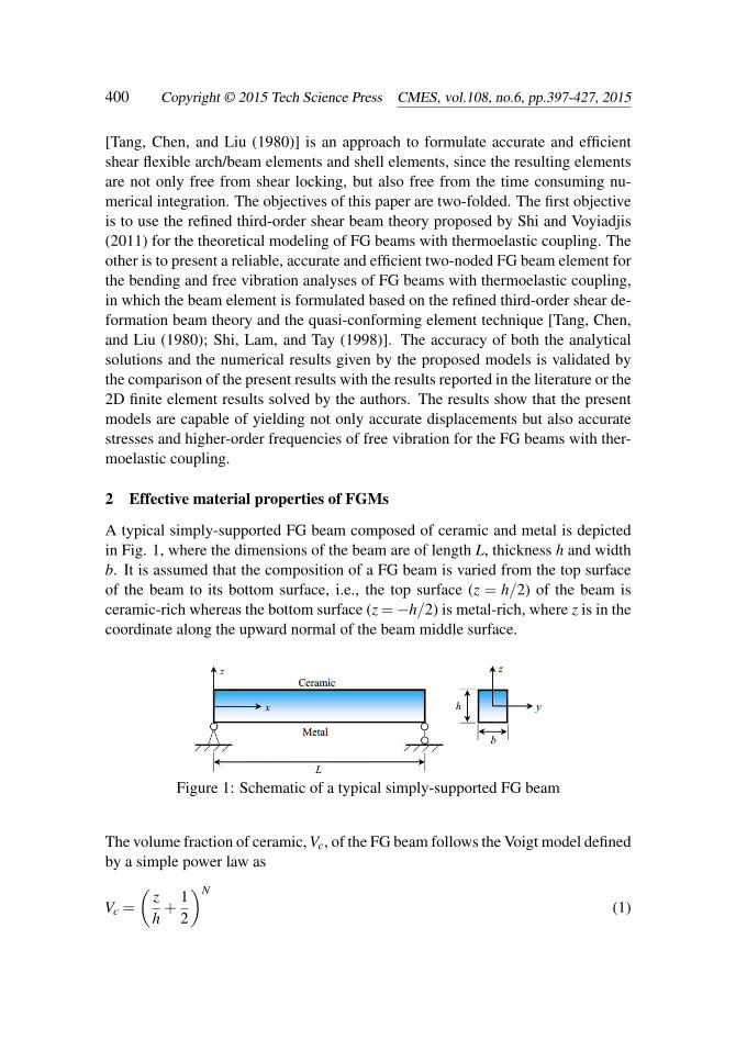
A typical simply-supported FG beam composed of ceramic and metal is depictedin Fig. 1, where the dimensions of the beam are of length L, thickness h and widthb. It is assumed that the composition of a FG beam is varied from the top surfaceof the beam to its bottom surface, i.e., the top surface (z = h/2) of the beam isceramic-rich whereas the bottom surface (z =−h/2) is metal-rich, where z is in thecoordinate along the upward normal of the beam middle surface.
Figure 1: Schematic of a typical simply-supported FG beam
The volume fraction of ceramic, Vc, of the FG beam follows the Voigt model definedby a simple power law as
Vc =
(zh+
12
)N
(1)
Analytical and FE Modeling of FG Beams Based on A Refined Shear Deformable 401
where N is the volume fraction index and takes only positive values (0≤ N < ∞).Then the effective material properties Pf , such as Young’s modulus E f and coeffi-cient of thermal expansion α f , can be characterized by
Pf = PcVc +PmVm (2)
in which Pc and Pm represent the material properties of ceramic and metal respec-tively; Vm is the metal volume fraction and it satisfies the relationship of Vc +Vm =1.
From Eqs. (1) and (2), one has
Pf (z) = [Pc−Pm]
(2z+h
2h
)N
+Pm (3)
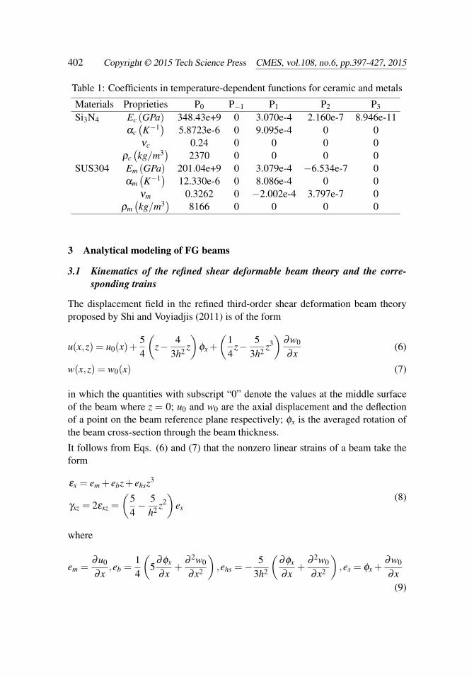
Since FG structures are most commonly used in high temperature environmen-t where significant changes in mechanical properties of the constituent materialsare to be expected, it is essential to take account of the temperature-dependency ofmaterial properties for the accurate prediction of the mechanical response. There-fore, the effective Young’s modulus E f and coefficient of thermal expansion α f ofFG beams are assumed to be temperature-dependent. They can be expressed as thefollowing nonlinear function of temperature [Touloukian (1967)]
where P0, P−1, P1, P2 and P3 are the coefficients of temperature T (K) which areunique to the constituent materials. Since the mass density ρ f depends weaklyon temperature change, it is assumed in this study that ρ f is a function of z on-ly. The effective material properties of selected Si3N4/SUS304 FGM are listed inTable 1 [Reddy and Chin (1998)]. A constant value of Poisson ratio is used forSi3N4/SUS304 FGM because there is only a small difference between the Poissonratios of ceramic and metal and the influence of the manor change of Poisson ratioon the structural response is negligible. The average value ν = 0.28 can be usedfor Si3N4/SUS304 FGM [Wattanasakulpong, Gangadhara, and Kelly (2010)].
The temperature field is assumed to be linearly distributed through the beam thick-ness when the FG beam is subjected to steady-state thermal loading, that is
T (z) =(Tt −Tb)z
h+
Tt +Tb
2(5)
The linear variation of temperature across FG beam thickness is justified when thethickness of a FG beam is within the dimension of milimeter. Substituting Eq. (5)into Eq. (4), the variation of FGM material properties through the beam thicknesscan be determined.
SUS304 Em (GPa) 201.04e+9 0 3.079e-4 −6.534e-7 0αm(K−1
)12.330e-6 0 8.086e-4 0 0
νm 0.3262 0 −2.002e-4 3.797e-7 0ρm(kg/m3
)8166 0 0 0 0
3 Analytical modeling of FG beams
3.1 Kinematics of the refined shear deformable beam theory and the corre-sponding trains
The displacement field in the refined third-order shear deformation beam theoryproposed by Shi and Voyiadjis (2011) is of the form
u(x,z) = u0(x)+54
(z− 4
3h2 z)
φx +
(14
z− 53h2 z3
)∂w0
∂x(6)
w(x,z) = w0(x) (7)
in which the quantities with subscript “0” denote the values at the middle surfaceof the beam where z = 0; u0 and w0 are the axial displacement and the deflectionof a point on the beam reference plane respectively; φx is the averaged rotation ofthe beam cross-section through the beam thickness.
It follows from Eqs. (6) and (7) that the nonzero linear strains of a beam take theform
εx = em + ebz+ ehsz3
γxz = 2εxz =
(54− 5
h2 z2)
es(8)
where
em =∂u0
∂x,eb =
14
(5
∂φx
∂x+
∂ 2w0
∂x2
),ehs =−
53h2
(∂φx
∂x+
∂ 2w0
∂x2
),es = φx +
∂w0
∂x(9)
Analytical and FE Modeling of FG Beams Based on A Refined Shear Deformable 403
3.2 Constitutive relations of FG beams
Under the bending in the x-z plane induced by thermal-mechanical coupling load-ing, the constitutive relations of shear flexible FG beams made of isotropic materialare of the form
{σ}={
σxx
τxz
}=
⌊Q11 00 Q55
⌋{εx−α(z,T )∆T (z)
γxz
}(10)
in which
Q11(z) = E(z,T ), Q55 =E(z,T )2(1+ v)
(11)
where ∆T (z) = T (z)−T0 is the temperature rise from the reference temperature T0at which there are no thermal strains.
3.3 Variational consistent equilibrium equations and the corresponding bound-ary conditions
It follows from Eqs. (8–10) that the strain energy of a FG beam with a length L andan area of cross section A can be defined in terms of the generalized displacementsu0, w0 and φx as
The various coefficients in the above expression are: A11 is the extensional stiff-ness, B11 is bending–extension coupling stiffness, D11 is bending stiffness, E11 iswarping–extension coupling stiffness, F11 is warping–bending coupling stiffness,H11 is warping–higher order bending coupling stiffness, S11 is shear stiffness; andNT , MT , PT are, respectively, the axial forces, bending moments and supplementarybending moment induced by thermal loading.
When the distributed bending moment is not considered, the external work of abeam performed by the distributed load q(x) per unit length acting on the beamsurface is of the form
We(w) =−∫ l
0q(x)w(x)dx (14)
Consequently, for a transverse shear deformable beam with the external load de-fined above, the corresponding variational principle leads to
δ[∏(u0,φx,w0)+We(w0)
]= 0 (15)
By substituting Eqs. (12) and (14) into Eq. (15), using integration by parts andcollecting the terms corresponding to δu0,δφx and δw0 in the line integral, oneobtains the following three differential equations:
∂
∂x
[−A11
(∂u0
∂x
)− B11
4
(5
∂φx
∂x+
∂ 2w0
∂x2
)+
5E11
3h2
(∂φx
∂x+
∂ 2w0
∂x2
)]= 0 (16)
∂ 2
∂x2
[B11
4
(∂u0
∂x
)+
D11
16
(5
∂φx
∂x+
∂ 2w0
∂x2
)− 5E11
3h2
(∂u0
∂x
)− 5F11
2h2 (17)(∂φx
∂x+
13
∂ 2w0
∂x2
)= 0 +
25H11
9h4
(∂φx
∂x+
∂ 2w0
∂x2
)]−S11
∂
∂x
(φx +
∂w0
∂x
)−q = 0
∂
∂x
[−5B11
4
(∂u0
∂x
)− 5D11
16
(5
∂φx
∂x+
∂ 2w0
∂x2
)+
5E11
3h2
(∂u0
∂x
)+
5F11
2h2(53
∂φx
∂x+
∂ 2w0
∂x2
)−25H11
9h4
(∂φx
∂x+
∂ 2w0
∂x2
)]+S11
(φx +
∂w0
∂x
)= 0 (18)
Denoting the generalized axial force corresponding to axial displacement u0 as F∗x ,the generalized bending moment acting on the beam cross section correspondingto φx as M∗x , the generalized transverse force corresponding to deflection w0 as
Analytical and FE Modeling of FG Beams Based on A Refined Shear Deformable 405
Q∗x and the supplementary bending moment corresponding to ∂w/∂x as MSx , these
quantities take the form
F∗x = A11∂u0
∂x+
B11
4
(5
∂φx
∂x+
∂ 2w0
∂x2
)− 5E11
3h2
(∂φx
∂x+
∂ 2w0
∂x2
)−NT (19)
Q∗x =∂
∂x
[−B11
4
(∂u0
∂x
)− D11
16
(5
∂φx
∂x+
∂ 2w0
∂x2
)+
5E11
3h2
(∂u0
∂x
)(20)
+5F11
2h2
(∂φx
∂x+
13
∂ 2w0
∂x2
)−25H11
9h4
(∂φx
∂x+
∂ 2w0
∂x2
)]+S11
(φx +
∂w0
∂x
)M∗x =
[5B11
4
(∂u0
∂x
)+
5D11
16
(5
∂φx
∂x+
∂ 2w0
∂x2
)− 5E11
3h2
(∂u0
∂x
)− 5F11
2h2
(53
∂φx
∂x+
∂ 2w0
∂x2
)+
25H11
9h4
(∂φx
∂x+
∂ 2w0
∂x2
)− 5
4MT +
53h2 PT
](21)
MSx =
[B11
4
(∂u0
∂x
)+
D11
16
(5
∂φx
∂x+
∂ 2w0
∂x2
)− 5E11
3h2
(∂u0
∂x
)− 5F11
2h2
(∂φx
∂x+
13
∂ 2w0
∂x2
)+
25H11
9h4
(∂φx
∂x+
∂ 2w0
∂x2
)− 1
4MT +
53h2 PT
](22)
Utilizing the generalized stress resultants and stress couples defined in Eqs. (19–22), the boundary conditions at the typical supports of transverse shear deformablebeams take the following form.
1. At a clamped support,
u0 = w0 = φx =∂w0
∂x= 0 (23)
2. At the end with displacement free but with specified stresses,
F∗x = Fx, Q∗x = Qx, M∗x = Mx, MSx = MS
x (24)
3. At a pin support,
u0 = 0, w0 = 0, M∗x = Mx, MSx = MS
x (25a)
4. At a roller support,
w0 = 0, F∗x = Fx, M∗x = Mx, MSx = MS
x (25b)
The quantities with “∼” in the above expressions denote the values given bythe specified stresses acting on the cross-section of beam end. The boundary
conditions of a simply supported beam are of the combination of Eqs. (25a and25b). It should be noted that under the action of thermal loading, the responseof a simple beam supported by the pin support at its both ends is different fromthat a simple beam supported by a pin support at one end and by a roller supportat the other.
4 Two-noded beam element of FG beams
The present formulation of FG beam element is based on the refined third-ordershear deformation beam theory proposed by Shi and Voyiadjis (2011), which hasbeen proved a high accuracy and efficiency in both static and dynamic analyses[Wang and Shi (2013)].
4.1 Strains of shear deformable FG beams
By using a shear variable γ defined as [Shi, Lam, and Tay (1998)]
γ =∂w0
∂x+φx (26)
then Eq. (6) can be rewritten as
u(x,z, t) = u0(x, t)− x(∂w0
∂x− γ)+(αz−β z3)γ (27)
with α = 1/4 and β = 5/(3h2).
It follows from Eq. (27) and Eq. (7) that the new expressions of the axial strain andthe transverse shear strain under consideration take the forms
εx = e∗m +αe∗bz−βe∗hsz3− εT , γxz = 2εxz =
(54− 5z2
h2
)e∗s (28)
in which
e∗m =∂u0
∂x, e∗b = 5
∂γ
∂x−4
∂ 2w0
∂x2 , e∗hs =∂γ
∂x, e∗s = γ, εT = α(z,T )∆T (z) (29)
The strains defined above are the functions of the deflection and transverse sheardeformation, and they results in a C1-continuity element under the displacement-based formulation. Corresponding to the strains defined in Eq. (29), the simplestnodal degrees of freedom at node i, qi, for a two-noded beam element can be chosenas
qi = [u0i,w0i,(∂w0
∂x)i,γi]
T , i = 1,2 (30)
Analytical and FE Modeling of FG Beams Based on A Refined Shear Deformable 407
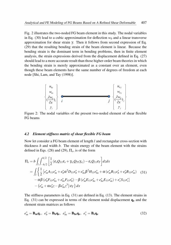
Fig. 2 illustrates the two-noded FG beam element in this study. The nodal variablesin Eq. (30) lead to a cubic approximation for deflection w0 and a linear transverseapproximation for shear strain γ . Then it follows from second expression of Eq.(29) that the resulting bending strain of the beam element is linear. Because thebending strain is the dominant term in bending problems, then in finite elementanalysis, the strain expressions derived from the displacement defined in Eq. (27)should lead to a more accurate result than those higher-order beam theories in whichthe bending strain is merely approximated as a constant over an element, eventhough these beam elements have the same number of degrees of freedom at eachnode [Shi, Lam, and Tay (1998)].
Figure 2: The nodal variables of the present two-noded element of shear flexibleFG beams
4.2 Element stiffness matrix of shear flexible FG beam
Now let consider a FG beam element of length l and rectangular cross-section withthickness h and width b. The strain energy of the beam element with the strainsdefined in Eqs. (28) and (29), Πe, is of the form
The stiffness parameters in Eq. (31) are defined in Eq. (13). The element strains inEq. (31) can be expressed in terms of the element nodal displacement qe and theelement strain matrices as follows
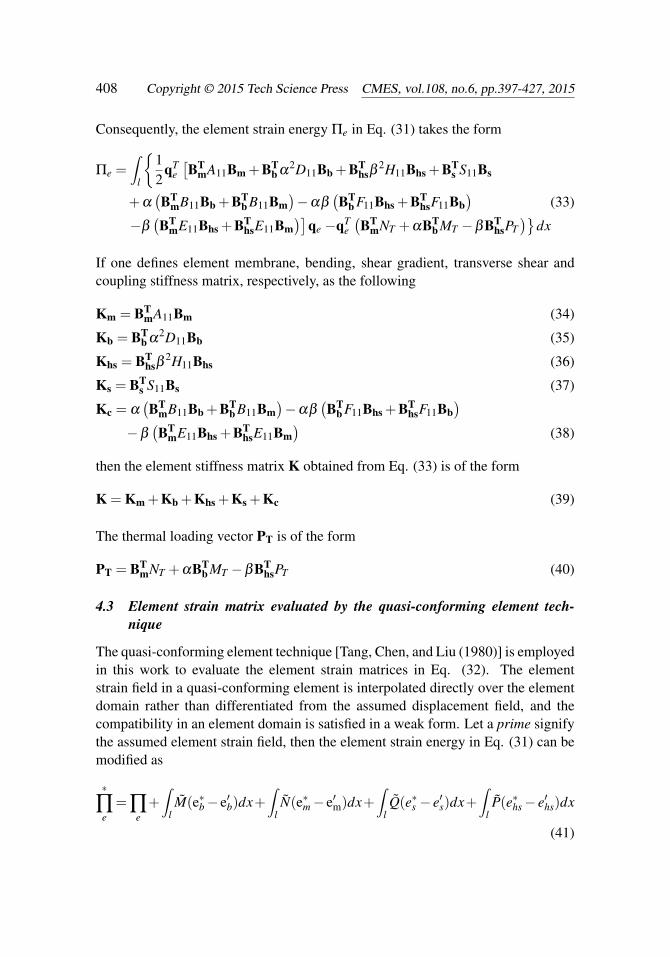
Consequently, the element strain energy Πe in Eq. (31) takes the form
Πe =∫
l
{12
qTe[BT
mA11Bm +BTb α
2D11Bb +BThsβ
2H11Bhs +BTs S11Bs
+α(BT
mB11Bb +BTb B11Bm
)−αβ
(BT
b F11Bhs +BThsF11Bb
)(33)
−β(BT
mE11Bhs +BThsE11Bm
)]qe −qT
e(BT
mNT +αBTb MT −βBT
hsPT)}
dx
If one defines element membrane, bending, shear gradient, transverse shear andcoupling stiffness matrix, respectively, as the following
Km = BTmA11Bm (34)
Kb = BTb α
2D11Bb (35)
Khs = BThsβ
2H11Bhs (36)
Ks = BTs S11Bs (37)
Kc = α(BT
mB11Bb +BTb B11Bm
)−αβ
(BT
b F11Bhs +BThsF11Bb
)−β
(BT
mE11Bhs +BThsE11Bm
)(38)
then the element stiffness matrix K obtained from Eq. (33) is of the form
K = Km +Kb +Khs +Ks +Kc (39)
The thermal loading vector PT is of the form
PT = BTmNT +αBT
b MT −βBThsPT (40)
4.3 Element strain matrix evaluated by the quasi-conforming element tech-nique
The quasi-conforming element technique [Tang, Chen, and Liu (1980)] is employedin this work to evaluate the element strain matrices in Eq. (32). The elementstrain field in a quasi-conforming element is interpolated directly over the elementdomain rather than differentiated from the assumed displacement field, and thecompatibility in an element domain is satisfied in a weak form. Let a prime signifythe assumed element strain field, then the element strain energy in Eq. (31) can bemodified as
∗
∏e=∏
e+∫
lM(e∗b− e′b)dx+
∫lN(e∗m− e′m)dx+
∫lQ(e∗s − e′s)dx+
∫lP(e∗hs− e′hs)dx
(41)
Analytical and FE Modeling of FG Beams Based on A Refined Shear Deformable 409
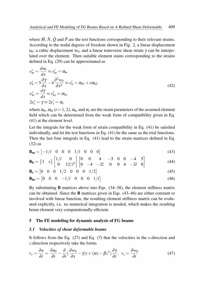
where M, N, Q and P are the test functions corresponding to their relevant strains.According to the nodal degrees of freedom shown in Fig. 2, a linear displacementu0, a cubic displacement w0, and a linear transverse shear strain γ can be interpo-lated over the element. Then suitable element stains corresponding to the strainsdefined in Eq. (29) can be approximated as
e∗m =du0
dx≈ e′m = αm
e∗b = 5∂γ
∂x−4
∂ 2w0
∂x2 ≈ e′b = αb1 + xαb2
e∗hs =dγ
dx≈ e′hs = αhs
2e∗s = γ ≈ 2e′s = αs
(42)
where αm,αbi (i= 1, 2), αhs and αs are the strain parameters of the assumed elementfield which can be determined from the weak form of compatibility given in Eq.(41) at the element level.
Let the integrals for the weak form of strain compatibility in Eq. (41) be satisfiedindividually, and let the test functions in Eq. (41) be the same as the trial functions.Then the last four integrals in Eq. (41) lead to the strain matrices defined in Eq.(32) as
Bm =[−1/l 0 0 0 1/l 0 0 0
](43)
Bb ={
1 x}[1/l 0
0 12/l3
][0 0 4 −5 0 0 −4 50 −4 −2l 0 0 4 −2l 0
](44)
Bs =[0 0 0 1/2 0 0 0 1/2
](45)
Bhs =[0 0 0 −1/l 0 0 0 1/l
](46)
By substituting B matrices above into Eqs. (34–38), the element stiffness matrixcan be obtained. Since the B matrices given in Eqs. (43–46) are either constant orinvolved with linear function, the resulting element stiffness matrix can be evalu-ated explicitly, i.e. no numerical integration is needed, which makes the resultingbeam element very computationally efficient.
5 The FE modeling for dynamic analysis of FG beams
5.1 Velocities of shear deformable beams
It follows from the Eq. (27) and Eq. (7) that the velocities in the x-direction andz-direction respectively take the forms
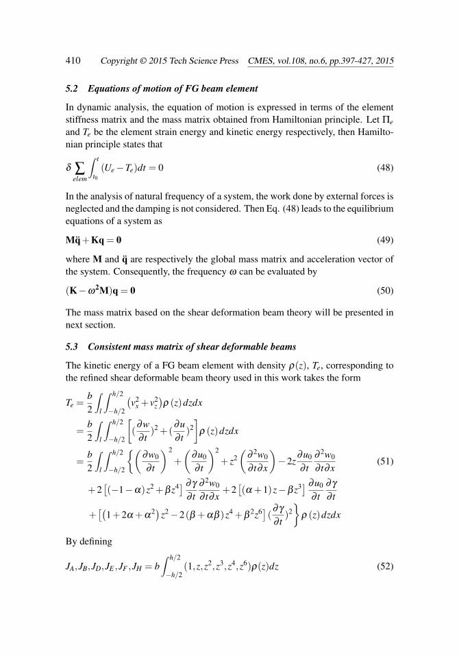
In dynamic analysis, the equation of motion is expressed in terms of the elementstiffness matrix and the mass matrix obtained from Hamiltonian principle. Let Πe
and Te be the element strain energy and kinetic energy respectively, then Hamilto-nian principle states that
δ ∑elem
∫ t
t0(Ue−Te)dt = 0 (48)
In the analysis of natural frequency of a system, the work done by external forces isneglected and the damping is not considered. Then Eq. (48) leads to the equilibriumequations of a system as
Mq+Kq = 0 (49)
where M and q are respectively the global mass matrix and acceleration vector ofthe system. Consequently, the frequency ω can be evaluated by
(K−ω2M)q = 0 (50)
The mass matrix based on the shear deformation beam theory will be presented innext section.
5.3 Consistent mass matrix of shear deformable beams
The kinetic energy of a FG beam element with density ρ(z), Te, corresponding tothe refined shear deformable beam theory used in this work takes the form
Te =b2
∫l
∫ h/2
−h/2
(v2
x + v2z)ρ (z)dzdx
=b2
∫l
∫ h/2
−h/2
[(∂w∂ t
)2 +(∂u∂ t
)2]
ρ (z)dzdx
=b2
∫l
∫ h/2
−h/2
{(∂w0
∂ t
)2
+
(∂u0
∂ t
)2
+ z2(
∂ 2w0
∂ t∂x
)−2z
∂u0
∂ t∂ 2w0
∂ t∂x(51)
+2[(−1−α)z2 +β z4] ∂γ
∂ t∂ 2w0
∂ t∂x+2[(α +1)z−β z3] ∂u0
∂ t∂γ
∂ t
+[(
1+2α +α2)z2−2(β +αβ )z4 +β
2z6](∂γ
∂ t)2}
ρ (z)dzdx
By defining
JA,JB,JD,JE ,JF ,JH = b∫ h/2
−h/2(1,z,z2,z3,z4,z6)ρ(z)dz (52)
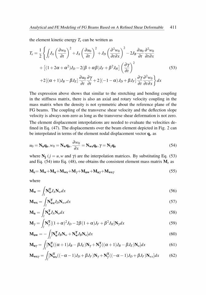
Analytical and FE Modeling of FG Beams Based on A Refined Shear Deformable 411
the element kinetic energy Te can be written as
Te =12
{∫lJA
(∂w0
∂ t
)2
+ JA
(∂u0
∂ t
)2
+ JD
(∂ 2w0
∂ t∂x
)2
−2JB∂u0
∂ t∂ 2w0
∂ t∂x
+[(1+2α +α
2)JD−2(β +αβ )JF +β2JH](∂γ
∂ t
)2
(53)
+2 [(α +1)JB−βJE ]∂u0
∂ t∂γ
∂ t+2 [(−1−α)JD +βJF ]
∂γ
∂ t∂ 2w0
∂ t∂x
}dx
The expression above shows that similar to the stretching and bending couplingin the stiffness matrix, there is also an axial and rotary velocity coupling in themass matrix when the density is not symmetric about the reference plane of theFG beams. The coupling of the transverse shear velocity and the deflection slopevelocity is always non-zero as long as the transverse shear deformation is not zero.
The element displacement interpolations are needed to evaluate the velocities de-fined in Eq. (47). The displacements over the beam element depicted in Fig. 2 canbe interpolated in terms of the element nodal displacement vector qe as
u0 = Nuqe,w0 = Nwqe,∂w0
∂x= Nwxqe,γ = Nγqe (54)
where Nj ( j = u,w and γ) are the interpolation matrices. By substituting Eq. (53)and Eq. (54) into Eq. (48), one obtains the consistent element mass matrix Me as
Mw, Mu and Mwx is, respectively, the usual transverse, axial and rotary inertiamatrices; Mγ is the mass matrix resulting from the higher-order displacement; andMuw, Muγ and Mwxγ are the coupling terms of different components of the axialdisplacement. The variational consistent mass matrix defined above can accountfor the contribution of the higher-order displacement to the mass matrix and theresults show that the consistent mass matrix can provide more accurate results thanthose given by lump mass matrix.
6 Examples of static analysis of FG beams
Analytical and numerical analyses based on the governing equations and the FGbeam element given in the previous sections are carried out to evaluate static de-flections and stresses of FG beams. The effects of the material distribution andthermal loading on the defections and stresses of various FG beams are studied bythe numerical results given by the present FG beam element, and the validation a-gainst other results is carried out to show the accuracy and efficiency of the presentFG beam element.
6.1 Convergence and accuracy study of the present FG beam element
A clamped-clamped FG beam with aspect ratio of L/h= 15 and subjected to a pointload F at the midspan is considered here. The beam is made of Si3N4/SUS304 withvolume fraction index N = 1000 (metal rich). Table 2 shows the convergence ofthe deflection given by the present FG beam element, in which the deflections ofFG beam are normalized as:
w =w×Em×h3×b
F×L3
The non-dimensional deflections obtained from different beam elements and theanalytical solution given by the present governing equations are tabulated in thetable. It can be seen from the results in the table that the present FG elementis more accurate than FGM-HSDT-RN and HSDT-FGM-SR presented by Kadoli,Akhtar, and Ganesan (2008), particularly when a coarse mesh is used.
6.2 Deflections of FG beams under mechanical loading
The influence of the volume fraction index on the deflections of FG beams is shownby the bending analysis of simply-supported FG beams under action of uniformlydistributed lateral load. The width of the beam is 0.1m and different aspect ratiosof L/h are considered. The FG beam is composed of Aluminum (Al: Em = 70 GPa,νm = 0.3) and Zirconia (ZrO2: Ec = 200 GPa, νc = 0.3). The top surface of the
Analytical and FE Modeling of FG Beams Based on A Refined Shear Deformable 413
Table 2: Calculated deflections of clamped FG beam with L/h = 15 and loaded atthe midspan
No. ofElements
FGM-HSDT-SR[Kadoli (2008)]
FGM-HSDT-RN[Kadoli (2008)]
Present FEresults
Present analyticalsolution
2 3.602 3.384 3.604 3.6185 3.602 3.573 3.604
20 3.605 3.604 3.604
beam is metal-rich whereas the bottom surface is ceramic-rich [Simsek (2009)] (itshould be noted that the volume fraction of ceramic Vc in the present example isdefined differently from that defined in Eq. (1)). The defections of the FG beam arenormalized by the static deflection of the fully aluminum beam under the uniformlydistributed load, w = w/(5ql4/384EAlIz).
The maximum non-dimensional deflections of the FG beams with different valuesof volume fraction indexes and aspect rations are listed in Table 3, where HOSDTstands for the higher-order shear deformation theory [Simsek (2009)] and BSWIstands for the B-spline wavelet on the interval finite element method [Zuo, Yang,Chen, Xie, Zhang, and Liu (2014)]. The use of the B-spline wavelet can achievevery accurate approximation for the field variables of one-dimensional beam prob-lems with the price of higher cost of computation. 20 elements are used in thepresent FEA to take account of the distributed load. Table 4 shows that the presentresults agree well with the results reported by Simsek (2009) and Zuo, Yang, Chen,Xie, Zhang, and Liu (2014), which demonstrates that the present FG beam elementis very accurate.
6.3 Axial stresses of modulus graded plate under uniaxial loading
The structures with FGMs behave differently from the structures made of conven-tional materials. Thus it is interesting and worthwhile to examine the axial stressdistribution of a structural member with graded modulus under the action of simpletensile loading. To this end, a cantilevered plate with modulus grading subjectedto a uniformly distributed tensile load at the free edge is considered. As shown inFig. 3, the non-dimensional width, length and thickness of the plate are 10, 10, and1 respectively [Dong, El-Gizawy, Juhany, and Atluri (2014b)]. Non-dimensionalYoung’s modulus of the plate is exponentially varying in the thickness direction zwhere E = eβ z with β = log5. Thus E = 1 at the lower surface and E = 5 at theupper surface of the plate. Poisson ratio v = 0 in this numerical example.
The cantilevered plate shown in Fig. 3 can be directly modeled as a cantilevered
Figure 3: A cantilevered modulus graded plate subjected to a tensile load
beam with a width of 10 since the Poisson ratio v = 0 in this plate. The axialstress at x = 5, y = 0 of the cantilevered plate with the graded modulus is computedby one element of the present FG beam element. The distribution of the resultingaxial stress across the plate thickness is displayed in Fig. 4, and the 3D elemen-t results obtained from the CEH8 C0 brick element given by Dong, El-Gizawy,Juhany, and Atluri (2014b) and the analytical solution given by Zhong and Yu
Analytical and FE Modeling of FG Beams Based on A Refined Shear Deformable 415
(2007) are also given in the figure. It should be noted that vertical axis z in Fig.4 denotes the plate thickness coordinate which is different from the coordinate sys-tem used by Dong, El-Gizawy, Juhany, and Atluri (2014b). The analytical solutionof Zhong and Yu (2007) was considered as the exact solution in the paper of Dong,El-Gizawy, Juhany, and Atluri (2014b). It should be pointed out that the presentstress results are deduced directly from the constitutive relations described in theprevious section. It can be seen from Fig. 4 that the axial stress prediction giv-en by the present FG beam element for this modulus graded plate coincides withthe exact solution even with a coarse mesh composed of only one beam element,which demonstrates that the present FG element are very computational efficientand accurate in the stress prediction.
Figure 4: Axial stress distribution across the plate thickness at x = 5, y = 0 for acantilevered modulus graded plate under uniformly distributed tensile load (N =1/length) at the free end.
6.4 Stresses of modulus graded beam under transverse force
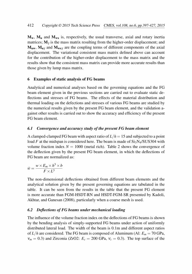
A cantilevered beam with modulus grading subjected to a unit transverse forceat the free end is considered in this example. As illustrated in Fig. 5, the non-dimensional length and thickness of the beam are 5 and 1 respectively [Dong, El-Gizawy, Juhany, and Atluri (2014a)]. Non-dimensional Young’s modulus is expo-nentially varying in the beam thickness direction, i.e. E = eβ z with β = log5. ThusE = 1 at the bottom surface of the beam, and E = 5 at its top surface. Poisson ratiov = 0 in this numerical example.
The axial stress of the cantilevered beam at x = 0.5 and the transverse shear stress
Figure 5: A cantilevered beam with graded modulus subjected to a transverse force
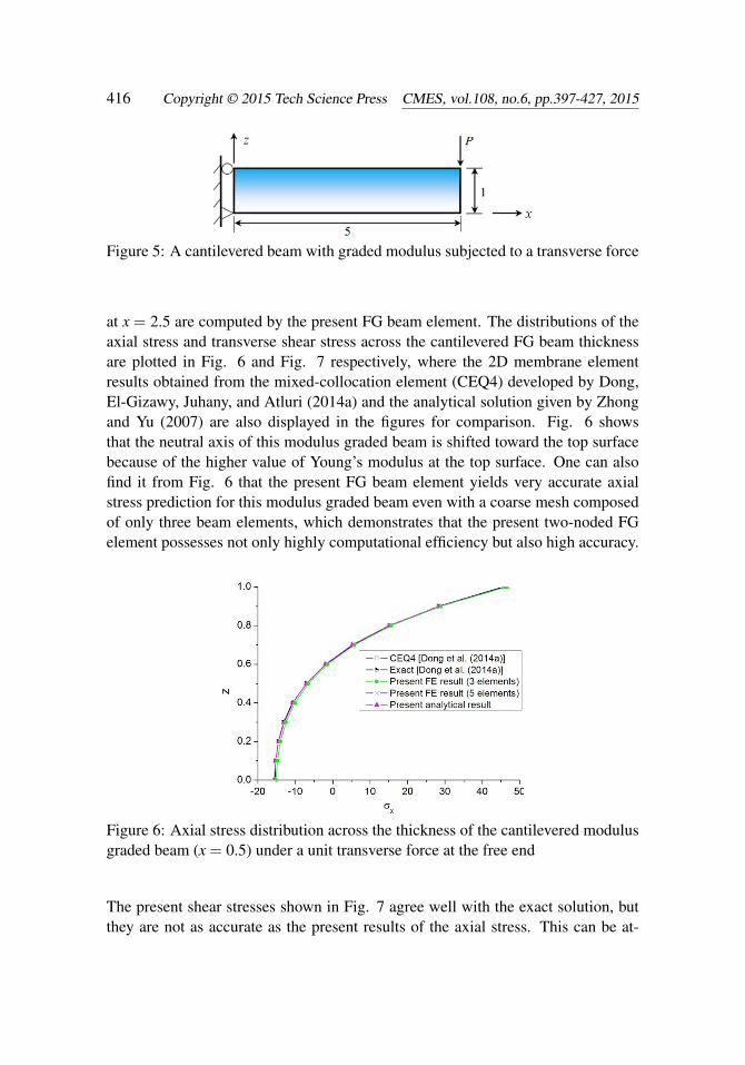
at x = 2.5 are computed by the present FG beam element. The distributions of theaxial stress and transverse shear stress across the cantilevered FG beam thicknessare plotted in Fig. 6 and Fig. 7 respectively, where the 2D membrane elementresults obtained from the mixed-collocation element (CEQ4) developed by Dong,El-Gizawy, Juhany, and Atluri (2014a) and the analytical solution given by Zhongand Yu (2007) are also displayed in the figures for comparison. Fig. 6 showsthat the neutral axis of this modulus graded beam is shifted toward the top surfacebecause of the higher value of Young’s modulus at the top surface. One can alsofind it from Fig. 6 that the present FG beam element yields very accurate axialstress prediction for this modulus graded beam even with a coarse mesh composedof only three beam elements, which demonstrates that the present two-noded FGelement possesses not only highly computational efficiency but also high accuracy.
Figure 6: Axial stress distribution across the thickness of the cantilevered modulusgraded beam (x = 0.5) under a unit transverse force at the free end
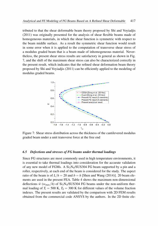
The present shear stresses shown in Fig. 7 agree well with the exact solution, butthey are not as accurate as the present results of the axial stress. This can be at-
Analytical and FE Modeling of FG Beams Based on A Refined Shear Deformable 417
tributed to that the shear deformable beam theory proposed by Shi and Voyiadjis(2011) was originally presented for the analysis of shear flexible beams made ofhomogeneous materials, in which the shear function is symmetric with respect tothe beam middle surface. As a result the symmetric shear function would resultin some error when it is applied to the computation of transverse shear stress ofa modulus graded beam that is a beam made of inhomogeneous material. Never-theless, the present shear stress results are satisfactory in general as shown in Fig.7, and the shift of the maximum shear stress can also be characterized correctly inthe present result, which indicates that the refined shear deformation beam theoryproposed by Shi and Voyiadjis (2011) can be efficiently applied to the modeling ofmodulus graded beams.
Figure 7: Shear stress distribution across the thickness of the cantilevered modulusgraded beam under a unit transverse force at the free end
6.5 Defections and stresses of FG beams under thermal loadings
Since FG structures are most commonly used in high temperature environments, itis essential to take thermal loadings into consideration for the accurate validationof any new model of FGMs. A Si3N4/SUS304 FG beam supported by a pin and aroller, respectively, at each end of the beam is considered for the study. The aspectratio of the beam is of L/h = 20 and b = h [Shen and Wang (2014)]. 20 beam ele-ments are used in the present FEA. Table 4 shows the maximum non-dimensionaldeflections w (wmax/h) of Si3N4/SUS304 FG beams under the non-uniform ther-mal loading of Tt = 500 K, Tb = 300 K for different values of the volume fractionindexes. The present results are validated by the comparison with 2D FEM resultsobtained from the commercial code ANSYS by the authors. In the 2D finite ele-
ment model of ANSYS, the gradations of Young’s modulus, coefficient of thermalexpansion and the temperature field across the beam thickness are modeled by anequivalent multilayered FG beam in which each lamina is assumed to be homoge-neous and equal thickness. Two lamination schemes of 40 laminae and 80 laminaerespectively along the FG beam thickness are used in the equivalent layered FGbeam models based on ANSYS to ensure the convergence of the numerical result-s given by the equivalent multilayered FG beam. Each lamina in the equivalentmultilayered beam model of the FG beam is meshed by two layers of Plane183 el-ements, and 800 elements are used in the beam axial direction. It can be seen fromTable 4 that the deflections given by the present FG beam element agree very wellwith the numerical results obtained from the 2D plane stress elements of ANSYS.
The distributions of the calculated axial stresses through the cross-section of themidspan of Si3N4/SUS304 FG beams induced by the thermal loading for the caseof volume fraction index N = 2 are plotted in Fig. 8. It can be seen from Fig. 8 thatthe ANSYS 2D results of the equivalent multilayered beam are approaching to thepresent FE results with the increase of the lamina number used for the equivalentmultilayered beam, which demonstrates the accuracy of the present stresses results.
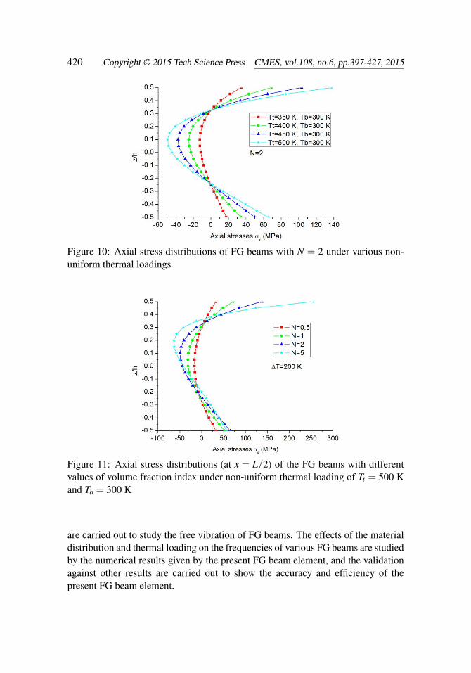
The influence of non-uniform thermal loading on the maximum non-dimensionaldeflections of Si3N4/SUS304 FG beams is depicted in Fig. 9, where different vol-ume fraction indexes are considered. Fig. 10 illustrates the axial stress distributionscross the FG beam thickness at the midspan of the Si3N4/SUS304 FG beams withN = 2 under different non-uniform thermal loadings.
The stress in a FG beam subjected to thermal loading also depends on the distribu-tion of its constituents. The influence of the volume fraction index of Si3N4/SUS304FG beams on the axial stress induced by non-uniform thermal loading is illustratedin Fig. 11, where Tt = 500 K, Tb = 300 K. It can be observed from Fig. 11 thatthe shift of the neutral surface of the FG beams gets larger as the increase of thevolume fraction index N.
The accuracy of the predicted stress of the FG beam elements under thermo-mechanicalcoupling loading is practically interested and important in the engineering applica-
Analytical and FE Modeling of FG Beams Based on A Refined Shear Deformable 419
Figure 8: Axial stress distribution across the cross-section (at x = L/2) ofSi3N4/SUS304 FG beam with N = 2 under non-uniform thermal loading of Tt =500 K and Tb = 300 K
Figure 9: Maximum non-dimensional deflections of FG beams versus non-uniformtemperature rise for different values of volume fraction index
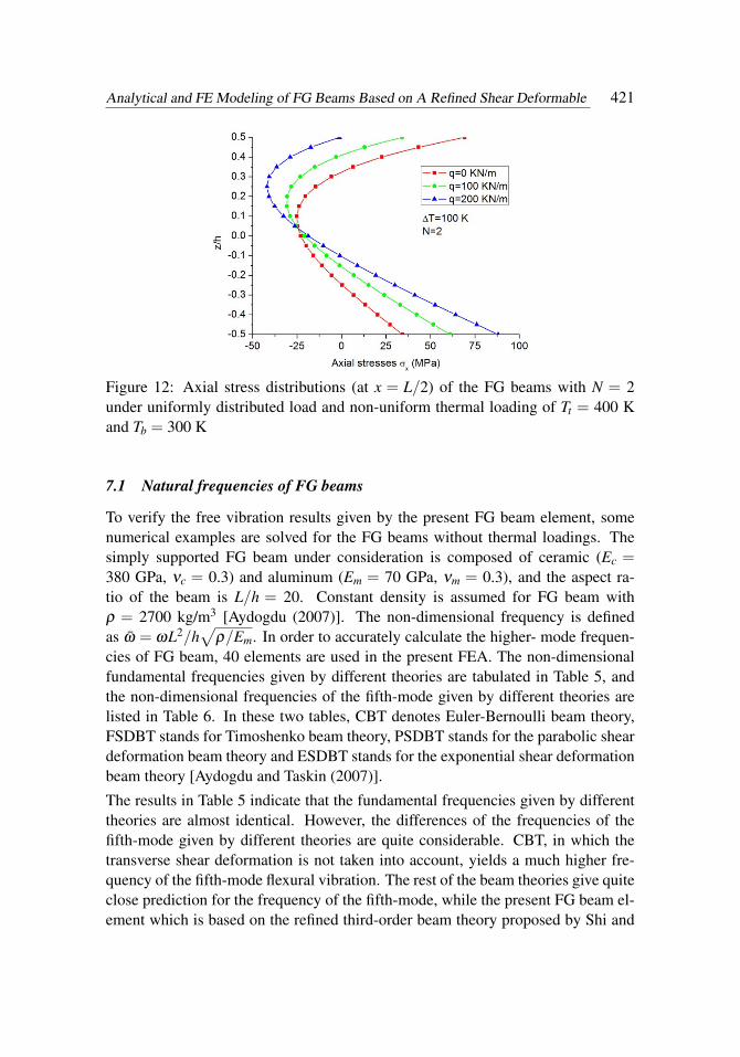
tion of FG beam. Fig. 12 shows the axial stress distributions of Si3N4/SUS304 FGbeams with N = 2 under different thermo-mechanical coupling loadings.
7 Examples of free vibration analysis of FG beams
Numerical analyses based on the FG beam element given in the previous sections
Figure 10: Axial stress distributions of FG beams with N = 2 under various non-uniform thermal loadings
Figure 11: Axial stress distributions (at x = L/2) of the FG beams with differentvalues of volume fraction index under non-uniform thermal loading of Tt = 500 Kand Tb = 300 K
are carried out to study the free vibration of FG beams. The effects of the materialdistribution and thermal loading on the frequencies of various FG beams are studiedby the numerical results given by the present FG beam element, and the validationagainst other results are carried out to show the accuracy and efficiency of thepresent FG beam element.
Analytical and FE Modeling of FG Beams Based on A Refined Shear Deformable 421
Figure 12: Axial stress distributions (at x = L/2) of the FG beams with N = 2under uniformly distributed load and non-uniform thermal loading of Tt = 400 Kand Tb = 300 K
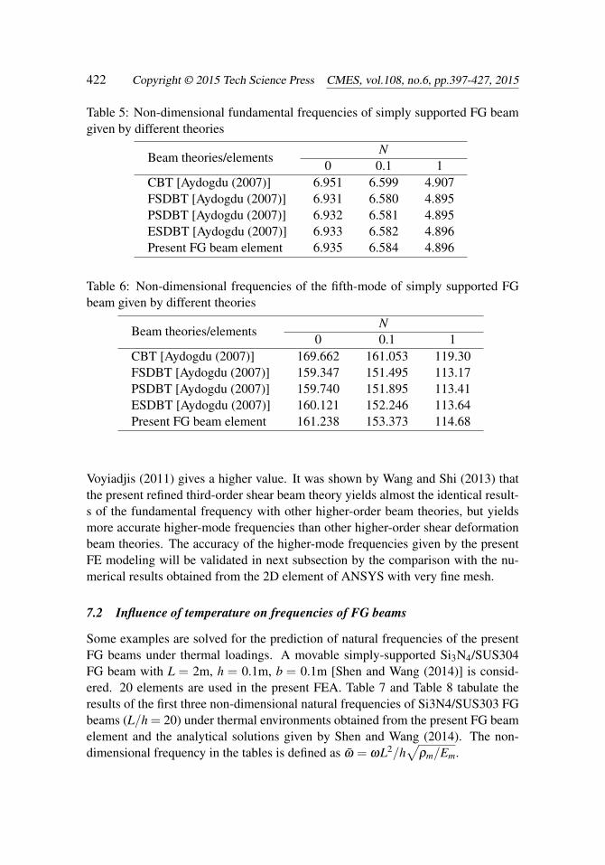
7.1 Natural frequencies of FG beams
To verify the free vibration results given by the present FG beam element, somenumerical examples are solved for the FG beams without thermal loadings. Thesimply supported FG beam under consideration is composed of ceramic (Ec =380 GPa, νc = 0.3) and aluminum (Em = 70 GPa, νm = 0.3), and the aspect ra-tio of the beam is L/h = 20. Constant density is assumed for FG beam withρ = 2700 kg/m3 [Aydogdu (2007)]. The non-dimensional frequency is definedas ω = ωL2/h
√ρ/Em. In order to accurately calculate the higher- mode frequen-
cies of FG beam, 40 elements are used in the present FEA. The non-dimensionalfundamental frequencies given by different theories are tabulated in Table 5, andthe non-dimensional frequencies of the fifth-mode given by different theories arelisted in Table 6. In these two tables, CBT denotes Euler-Bernoulli beam theory,FSDBT stands for Timoshenko beam theory, PSDBT stands for the parabolic sheardeformation beam theory and ESDBT stands for the exponential shear deformationbeam theory [Aydogdu and Taskin (2007)].
The results in Table 5 indicate that the fundamental frequencies given by differenttheories are almost identical. However, the differences of the frequencies of thefifth-mode given by different theories are quite considerable. CBT, in which thetransverse shear deformation is not taken into account, yields a much higher fre-quency of the fifth-mode flexural vibration. The rest of the beam theories give quiteclose prediction for the frequency of the fifth-mode, while the present FG beam el-ement which is based on the refined third-order beam theory proposed by Shi and
Voyiadjis (2011) gives a higher value. It was shown by Wang and Shi (2013) thatthe present refined third-order shear beam theory yields almost the identical result-s of the fundamental frequency with other higher-order beam theories, but yieldsmore accurate higher-mode frequencies than other higher-order shear deformationbeam theories. The accuracy of the higher-mode frequencies given by the presentFE modeling will be validated in next subsection by the comparison with the nu-merical results obtained from the 2D element of ANSYS with very fine mesh.
7.2 Influence of temperature on frequencies of FG beams
Some examples are solved for the prediction of natural frequencies of the presentFG beams under thermal loadings. A movable simply-supported Si3N4/SUS304FG beam with L = 2m, h = 0.1m, b = 0.1m [Shen and Wang (2014)] is consid-ered. 20 elements are used in the present FEA. Table 7 and Table 8 tabulate theresults of the first three non-dimensional natural frequencies of Si3N4/SUS303 FGbeams (L/h = 20) under thermal environments obtained from the present FG beamelement and the analytical solutions given by Shen and Wang (2014). The non-dimensional frequency in the tables is defined as ω = ωL2/h
√ρm/Em.
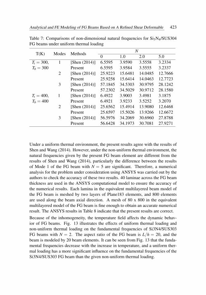
Analytical and FE Modeling of FG Beams Based on A Refined Shear Deformable 423
Table 7: Comparisons of non-dimensional natural frequencies for Si3N4/SUS304FG beams under uniform thermal loading
Under a uniform thermal environment, the present results agree with the results ofShen and Wang (2014). However, under the non-uniform thermal environment, thenatural frequencies given by the present FG beam element are different from theresults of Shen and Wang (2014), particularly the difference between the resultsof Mode 1 of the FG beam with N = 5 are significant. Therefore, a numericalanalysis for the problem under consideration using ANSYS was carried out by theauthors to check the accuracy of these two results. 40 laminae across the FG beamthickness are used in the ANSYS computational model to ensure the accuracy ofthe numerical results. Each lamina in the equivalent multilayered beam model ofthe FG beam is meshed by two layers of Plane183 elements, and 800 elementsare used along the beam axial direction. A mesh of 80 x 800 in the equivalentmultilayered model of the FG beam is fine enough to obtain an accurate numericalresult. The ANSYS results in Table 8 indicate that the present results are correct.
Because of the inhomogeneity, the temperature field affects the dynamic behav-ior of FG beams. Fig. 13 illustrates the effects of uniform thermal loading andnon-uniform thermal loading on the fundamental frequencies of Si3N4/SUS303FG beams with N = 2. The aspect ratio of the FG beam is L/h = 20, and thebeam is modeled by 20 beam elements. It can be seen from Fig. 13 that the funda-mental frequencies decrease with the increase in temperature, and a uniform ther-mal loading has a more significant influence on the fundamental frequencies of theSi3N4/SUS303 FG beam than the given non-uniform thermal loading.
Figure 13: Non-dimensional fundamental frequencies of Si3N4/SUS304 FG beamswith N = 2 under uniform thermal loading and non-uniform thermal loading
8 Conclusion
This paper presents the analytical and FE modeling of FG beams for the static anddynamic analyses of the FG beams with thermoelastic coupling. The governingequations of FG beams are derived by using a refined third-order shear deformationbeam theory and the variational principle. An accurate and reliable two-nodedbeam element is developed based on the refined third-order shear deformation beamtheory and the quasi-conforming element technique. The analytical solutions of
Analytical and FE Modeling of FG Beams Based on A Refined Shear Deformable 425
the bending problems of FG beams under thermal loading are solved using thepresent governing equations of FG beams. A number of numerical examples of thebending and free vibration of FG beams with thermoelastic coupling are solved bythe two-noded FG beam element, and the accuracy of the present numerical resultsis validated with the results reported in the literature or the 2D finite element resultssolved by the authors. Both the analytical solutions and the numerical results showthat the analytical model and the FG beam element presented in this work have thefollowing features.
1. The geometric middle surface of FG beams can be efficiently used as thereference surface, i.e. the surface with z = 0, in the chosen refined third-order shear deformation beam theory to achieve accurate results in the staticand dynamic thermoelastic analyses of FG beams with different values of thevolume fraction index and thermoelastic coupling.
2. The two noded FG beam element given in this study is not only efficient,but also capable of yielding very accurate stresses and frequencies of higher-mode vibration of FG beams with thermoelastic coupling, although merely acoarse mesh of beam elements is used in the numerical analysis.
Acknowledgement: The financial support provided by the grant of NSFC-91230113is thankfully acknowledged.
References
Aydogdu, M.; Taskin, V. (2007): Free vibration analysis of functionally gradedbeams with simply supported edges. Mater. Design., vol. 28, pp. 1651–1656.
Birman, V.; Byrd, L. W. (2007): Modeling and analysis of functionally gradedmaterials and structures, Appl. Mech. Rev., vol. 60, no. 5, pp. 195–216.
Chakraborty, A.; Gopalakrishnan, S.; Reddy, J. N. (2003): A new beam finiteelement for the analysis of functionally graded materials. Int. J. Mech. Sci., vol. 45,no. 3, pp. 519–539.
Dong, L.; El-Gizawy, A. S.; Juhany, K. A.; Atluri, S. N. (2014a): A simplelocking-alleviated 4-node mixed-collocation finite element with over-integration,for homogeneous or functionally-graded or thick-section laminated compositebeams. CMC: Computers Materials & Continua, vol. 40, no. 1, pp. 49–77.
Dong, L.; El-Gizawy, A. S.; Juhany, K. A.; Atluri, S. N. (2014b): A sim-ple locking-alleviated 3D 8-Node mixed-collocation C0 finite element with over-Integration, for functionally-graded and laminated thick-section plates and shells,
with & without Z-Pins. CMC: Computers Materials & Continua, vol. 41, no.3 pp.163–192.
Ebrahimi, F.; Salari, E. (2015): A semi-analytical method for vibrational andbuckling analysis of functionally graded nanobeams considering the physical neu-tral axis position. CEMS: Computer Modeling in Engineering & Sciences, vol. 105,no. 2, pp. 151–181.
Giunta, G.; Crisafulli, D.; Belouettar, S.; Carrera, E. (2013): A thermo-mechanical analysis of functionally graded beams via hierarchical modelling. Com-pos. Struct., vol. 95, no. 1, pp. 676–690.
Kadoli, R.; Akhtar, K.; Ganesan, N. (2008): Static analysis of functionally grad-ed beams using higher order shear deformation theory. Appl. Math. Model., vol. 32,no. 12, pp. 2509–2525.
Lü, C.; Chen, W.; Xu, R.; Lim, C. W. (2008): Semi-analytical elasticity solutionsfor bi-directional functionally graded beams. Int. J. Solids Struct., vol. 45, no. 1,pp. 258–275.
Mahi, A.; Adda Bedia, E. A.; Tounsi, A.; Mechab, I. (2010): An analyticalmethod for temperature-dependent free vibration analysis of functionally gradedbeams with general boundary conditions. Compo. Struct., vol. 92, no. 8, pp. 1877–1887.
Noda, N. (1999): Thermal stresses in functionally graded materials. J. Therm.Stresses, vol. 22, no. 4, pp. 477–512.
Ray, M. C.; Dong, L.; Atluri, S. N. (2015): Simple efficient smart finite elementsfor the analysis of smart composite beams. CMC: Computers Materials & Contin-ua, vol. 37, no. 2, pp. 65–99.
Reddy, J. N.; Chin, C. D. (1998): Thermomechanical analysis of functionallygraded cylinders and plates. J. Therm. Stresses, vol. 21, no. 6, pp. 593–626.
Sankar, B. V.; Tzeng, J. T. (2002): Thermal stresses in functionally graded beams.AIAA J., vol. 40, no. 6, pp. 1228–1232.
Shen, H.; Wang, Z. (2014): Nonlinear analysis of shear deformable FGM beamsresting on elastic foundations in thermal environments. Int. J. Mech. Sci., vol. 81,no. 4, pp. 195–206.
Shi, G.; Voyiadjis, G. Z. (1991): Simple and efficient shear flexible two-nodearch/beam and four-node cylindrical shell/plate finite elements. Int. J. Num. Meth.Eng., vol. 31, pp. 759–776.
Analytical and FE Modeling of FG Beams Based on A Refined Shear Deformable 427
Shi, G.; Lam, K. Y.; Tay, T. E. (1998): On efficient finite element modelling ofcomposite beams and plates using higher-order theories and an accurate compositebeam element. Compos. Struct., vol. 41, no. 2, pp. 159–165.
Shi, G.; Voyiadjis, G. Z. (2011): A sixth-order theory of shear deformable beamswith variational consistent boundary conditions. J. Appl. Mech., vol. 78, no. 2, pp.856–875.
Simsek, M. (2009): Static analysis of a functionally graded beam under a uniform-ly distributed load by Ritz method. Int. J. Eng. Appl. Sci., vol. 1, no. 3, pp. 1-11.
Tang, L.; Chen, W.; Liu, Y. (1980): Quasi-conforming element for finite elementanalysis. J. Dalian Inst. Tech., vol. 19, no. 2, pp. 19–35. (in Chinese)
Thai, H. T.; Kim, S. E. (2015): A review of theories for the modeling and analysisof functionally graded plates and shells. Compos. Struct., vol. 128, pp. 70–86.
Touloukian, Y. S. (1967): Thermophysical Properties of High Temperature SolidsMaterials. New York, MacMillan.
Wang, X.; Shi, G. (2012): The boundary layer solutions induced by displacementboundary conditions of shear deformable beams and accuracy study of higher-orderbeam theories. J. Eng. Mech. AMCE, vol. 138, no. 11, pp. 1388–1399.
Wang, X.; Shi, G. (2013): A new assumed strain beam element based on a sixth-order beam theory for static and dynamic analysis of composite beams. APCOM &ISCM, 11–14th December, Singapore.
Wattanasakulpong, N.; Gangadhara, P. B.; Kelly, D. W. (2011): Thermal buck-ling and elastic vibration of third-order shear deformable functionally graded beam-s. Int. J. Mech. Sci., vol. 53, no. 9, pp. 734–43.
Zhang, B.; He, Y.; Liu, D.; Gan, Z.; Shen, L. (2014): Size-dependent functional-ly graded beam model based on an improved third-order shear deformation theory.Eur. J. Mech A-Solid., vol. 47, pp. 211-230.
Zhang, D. (2013): Nonlinear bending analysis of FGM beams based on physicalneutral surface and high order shear deformation theory. Compos. Struct., vol. 100,no. 5, pp. 121–126.
Zhong, Z.; Yu, T. (2007): Analytical solution of a cantilever functionally gradedbeam. Compos. Sci. Technol., vol. 67, no. 3, pp. 481–488.
Zuo, H.; Yang, Z. B.; Chen, X. F.; Xie, Y.; Zhang, X. W.; Liu, Y. (2014): Stat-ic, free vibration and buckling analysis of functionally graded beam via B-splinewavelet on the interval and Timoshenko beam theory. CEMS: Computer Modelingin Engineering & Sciences, vol. 100, no. 6, pp. 477–506.