30
SUPPLEMENTARY OPERATING INSTRUCTIONS Title Page Description Operating Functions Technical Data Analyzer Module UNOR-MULTOR for Series GMS800
S U P P L E M E N T A R Y O P E R A T I N G I N S T R U C T I O N STitle Page
DescriptionOperating FunctionsTechnical Data
Analyzer Module UNOR-MULTORfor Series GMS800
2 UNOR-MULTOR · Supplementary Operating Instructions · 8013027 V 2.0 · © SICK AG
Document Information
Described ProductProduct name: Analyzer Module UNOR-MULTOR Basic device: Series GMS800 gas analyzers
Document IDTitle: Supplementary Operating Instructions
UNOR-MULTORPart No.: 8013027Version: 2.0Release: 2012-12
ManufacturerSICK AGErwin-Sick-Str. 1 · D-79183 Waldkirch · GermanyPhone: +49 7641 469-0Fax: +49 7641 469-1149E-mail: [email protected]
TrademarksViton is a trademark of DuPont Performance Elastomers.Other product names used in this document may be trademarks and are only used for identification purposes.
Original documentsThe English edition 8013027 of this document is an original docu-ment of the manufacturer.SICK AG assumes no liability for the correctness of an unauthor-ized translation.Please contact the manufacturer in case of doubt.
Legal informationSubject to change without notice
© SICK AG. All rights reserved.
Glossary
Warning Symbols
Signal Words
CAUTIONHazard or unsafe practice which could result in personal injury or property damage.
NOTICEHazard which could result in property damage.
Information Symbols
IR Infrared (infrared light)
NDIR Non-dispersive infrared; Designation for optical gas analysis methods in infrared spectral range
PC Personal Computer
SOPAS SICK Open Portal for Applications and Systems: Family of computer programs to set parameters, capture and calculate data.
SOPAS ET SOPAS Engineering Tool: PC application program to configure modular system components.
Hazard (general)
Important technical information for this product
Nice to know
Supplementary information
Link to information at another place
ContentsContents
1 Important Information . . . . . . . . . . . . . . . . . . . . . . . . . . . . . . . . . . . . . . . . . . . . . . . 5
1.1 Main operating information . . . . . . . . . . . . . . . . . . . . . . . . . . . . . . . . . . . . . . . . . . . . . . . . . . . . 6
1.2 Application limitations . . . . . . . . . . . . . . . . . . . . . . . . . . . . . . . . . . . . . . . . . . . . . . . . . . . . . . . . 6
1.3 Additional documentation/information . . . . . . . . . . . . . . . . . . . . . . . . . . . . . . . . . . . . . . . . . 6
1.4 Safety information on disposal . . . . . . . . . . . . . . . . . . . . . . . . . . . . . . . . . . . . . . . . . . . . . . . . . 6
2 Product Description . . . . . . . . . . . . . . . . . . . . . . . . . . . . . . . . . . . . . . . . . . . . . . . . . . . 7
2.1 Measuring system . . . . . . . . . . . . . . . . . . . . . . . . . . . . . . . . . . . . . . . . . . . . . . . . . . . . . . . . . . . . 9
2.2 Options . . . . . . . . . . . . . . . . . . . . . . . . . . . . . . . . . . . . . . . . . . . . . . . . . . . . . . . . . . . . . . . . . . . . . 102.2.1 Adjustment unit (option) . . . . . . . . . . . . . . . . . . . . . . . . . . . . . . . . . . . . . . . . . . . . . . . . . . . 102.2.2 Purge cuvettes . . . . . . . . . . . . . . . . . . . . . . . . . . . . . . . . . . . . . . . . . . . . . . . . . . . . . . . . . . . . 10
3 Installation Information . . . . . . . . . . . . . . . . . . . . . . . . . . . . . . . . . . . . . . . . . . . . . 11
3.1 Sample gas feed . . . . . . . . . . . . . . . . . . . . . . . . . . . . . . . . . . . . . . . . . . . . . . . . . . . . . . . . . . . . 12
3.2 Purge gas feed for purge cuvettes . . . . . . . . . . . . . . . . . . . . . . . . . . . . . . . . . . . . . . . . . . . . . 12
4 Functions in SOPAS ET . . . . . . . . . . . . . . . . . . . . . . . . . . . . . . . . . . . . . . . . . . . . . . 13
4.1 Menu tree in SOPAS ET . . . . . . . . . . . . . . . . . . . . . . . . . . . . . . . . . . . . . . . . . . . . . . . . . . . . . . 14
4.2 Explanation of the menus in SOPAS ET . . . . . . . . . . . . . . . . . . . . . . . . . . . . . . . . . . . . . . . . 16
4.3 Explanation of functions . . . . . . . . . . . . . . . . . . . . . . . . . . . . . . . . . . . . . . . . . . . . . . . . . . . . . 184.3.1 Logbook in SOPAS ET . . . . . . . . . . . . . . . . . . . . . . . . . . . . . . . . . . . . . . . . . . . . . . . . . . . . . . 184.3.2 Upload (data synchronization) . . . . . . . . . . . . . . . . . . . . . . . . . . . . . . . . . . . . . . . . . . . . . . 184.3.3 Damping . . . . . . . . . . . . . . . . . . . . . . . . . . . . . . . . . . . . . . . . . . . . . . . . . . . . . . . . . . . . . . . . . 194.3.4 Drift limit values . . . . . . . . . . . . . . . . . . . . . . . . . . . . . . . . . . . . . . . . . . . . . . . . . . . . . . . . . . 204.3.5 Deleting adjustment results . . . . . . . . . . . . . . . . . . . . . . . . . . . . . . . . . . . . . . . . . . . . . . . . 20
5 Adjustment Information . . . . . . . . . . . . . . . . . . . . . . . . . . . . . . . . . . . . . . . . . . . . 21
5.1 Setting parameters and controlling adjustments . . . . . . . . . . . . . . . . . . . . . . . . . . . . . . . . 22
5.2 Adjustment interval . . . . . . . . . . . . . . . . . . . . . . . . . . . . . . . . . . . . . . . . . . . . . . . . . . . . . . . . . . 22
5.3 Using the adjustment unit (option) . . . . . . . . . . . . . . . . . . . . . . . . . . . . . . . . . . . . . . . . . . . . 22
5.4 H2O adjustment for measured components SO2 and NO . . . . . . . . . . . . . . . . . . . . . . . . 22
6 Technical Data . . . . . . . . . . . . . . . . . . . . . . . . . . . . . . . . . . . . . . . . . . . . . . . . . . . . . . . . 23
6.1 Installation location requirements . . . . . . . . . . . . . . . . . . . . . . . . . . . . . . . . . . . . . . . . . . . . 24
6.2 Metrological specifications . . . . . . . . . . . . . . . . . . . . . . . . . . . . . . . . . . . . . . . . . . . . . . . . . . . 24
6.3 Gas technical requirements . . . . . . . . . . . . . . . . . . . . . . . . . . . . . . . . . . . . . . . . . . . . . . . . . . 256.3.1 Sample gas. . . . . . . . . . . . . . . . . . . . . . . . . . . . . . . . . . . . . . . . . . . . . . . . . . . . . . . . . . . . . . . 256.3.2 Purge gas . . . . . . . . . . . . . . . . . . . . . . . . . . . . . . . . . . . . . . . . . . . . . . . . . . . . . . . . . . . . . . . . 25
6.4 Materials with sample gas contact . . . . . . . . . . . . . . . . . . . . . . . . . . . . . . . . . . . . . . . . . . . . 25
6.5 Measuring ranges . . . . . . . . . . . . . . . . . . . . . . . . . . . . . . . . . . . . . . . . . . . . . . . . . . . . . . . . . . . 26
6.6 Approvals . . . . . . . . . . . . . . . . . . . . . . . . . . . . . . . . . . . . . . . . . . . . . . . . . . . . . . . . . . . . . . . . . . . 27
6.7 Auxiliary power supply for the module . . . . . . . . . . . . . . . . . . . . . . . . . . . . . . . . . . . . . . . . . 27
UNOR-MULTOR · Supplementary Operating Instructions · 8013027 V 2.0 · © SICK AG 3

Contents
4 UNOR-MULTOR · Supplementary Operating Instructions · 8013027 V 2.0 · © SICK AG
Important Information
Subj
ect t
o ch
ange
with
out n
otic
e
UNOR-MULTOR
1 Important Information
Operating information
Application limitations
Additional documentation
UNOR-MULTOR · Supplementary Operating Instructions · 8013027 V 2.0 · © SICK AG 5
Important Information
Subj
ect t
o ch
ange
with
out n
otic
e
1 . 1 Main operating information● Electric motor operating noises are normal.
1 . 2 Application limitationsIt is possible that another gas component contained in the sample gas can influence theanalysis of the desired measuring component (cross-sensitivity).
In such a case, a constant concentration of the “interfering gas” creates a constant devia-tion from the true measured value every time (constant characteristic curve offset). Thedeviation varies accordingly when the interfering gas concentration fluctuates.
1 . 3 Additional documentation/informationThis document supplements the Operating Instructions for GMS800 gas analyzers. Itextends the “GMS800“ Operating Instructions with technical information on the UNOR-MULTOR.
▸ Observe the Operating Instructions delivered with the “GMS800”.
1 . 4 Safety information on disposal In many applications, the “measuring chamber” of the Analyzer module is filled with a gasor gas mixture. This can also apply to the reference side of the cuvette.
▸ Before the measuring chamber or cuvette is opened or severely damaged: Check whether this component could contains dangerous gases. In case of doubt, contact the manufacturer's factory.
▸ If the component could contain dangerous gases: Only allow skilled persons with corre-sponding knowledge to dispose of such components and take appropriate protective measures at the same time (e.g. respirator mask, suctioning off, ventilation).
● Cross-sensitivity against a certain gas is minimized automatically when the UNOR-MULTOR also measures the concentration of this gas.
● The cross-sensitivity can be minimized through computation in the control unit when the interfering gas concentration is measured with a different Analyzer module in the GMS800.
The “GMS800” Operating Instructions also specify all further documents belonging to the individual device.
NOTICE:▸ Pay primary attention to any individual information provided.
6 UNOR-MULTOR · Supplementary Operating Instructions · 8013027 V 2.0 · © SICK AG
Product Description
Subj
ect t
o ch
ange
with
out n
otic
e
UNOR-MULTOR
2 Product Description
Measuring principle
Measuring ranges
UNOR-MULTOR · Supplementary Operating Instructions · 8013027 V 2.0 · © SICK AG 7
Product Description
Subj
ect t
o ch
ange
with
out n
otic
e
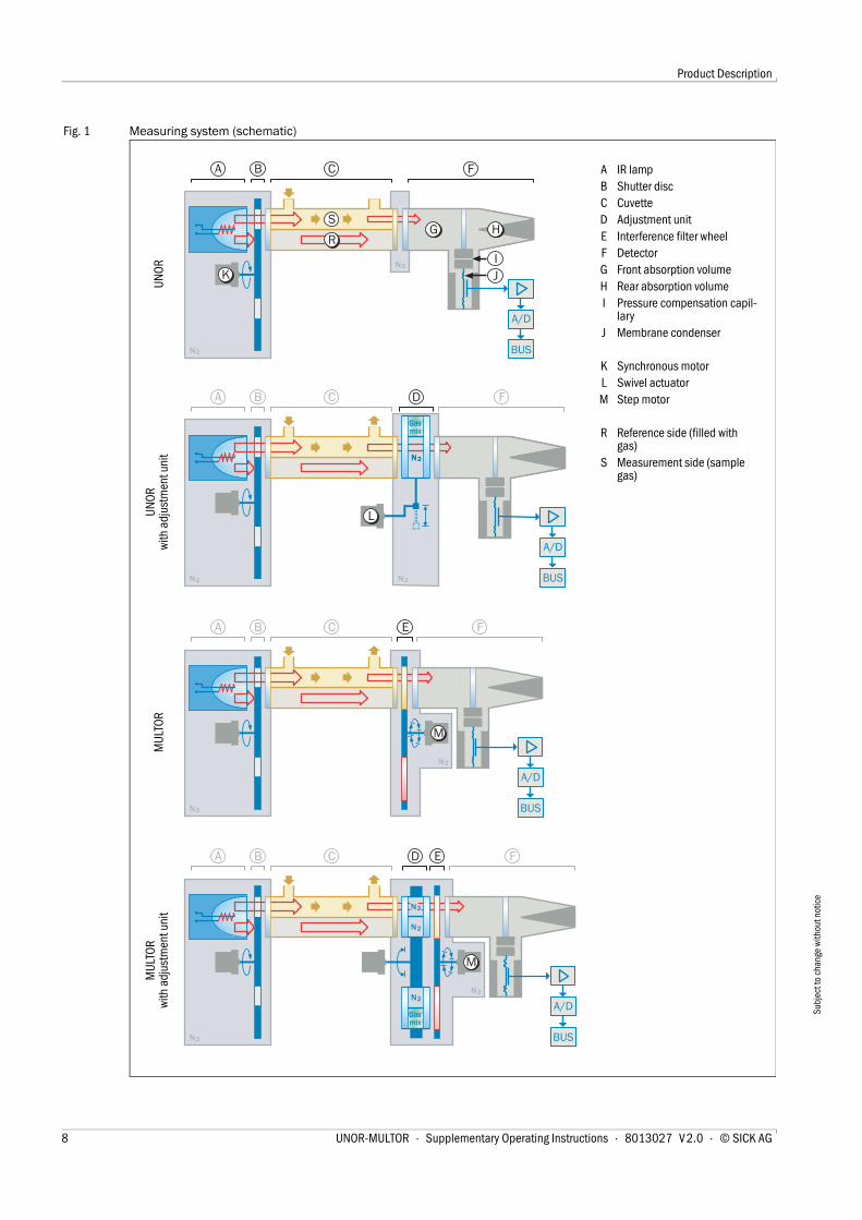
Fig. 1 Measuring system (schematic)
N2
N2
Gasmix
N2N2
N2
F
G H
N2
Gasmix
CB
SR
K
N2
N2
IJ
A/D
BUS
A/D
BUS
A/D
BUS
A/D
BUS
M
N2
N2
L
N2
N2
A
A
A
N2
A
FDCB
FDCB E
FCB E
M
A IR lampB Shutter discC CuvetteD Adjustment unitE Interference filter wheelF DetectorG Front absorption volumeH Rear absorption volumeI Pressure compensation capil-
laryJ Membrane condenser
K Synchronous motorL Swivel actuatorM Step motor
R Reference side (filled with gas)
S Measurement side (sample gas)
UNO
RUN
OR
with
adj
ustm
ent u
nit
MUL
TOR
MUL
TOR
with
adj
ustm
ent u
nit
8 UNOR-MULTOR · Supplementary Operating Instructions · 8013027 V 2.0 · © SICK AG
Product Description
Subj
ect t
o ch
ange
with
out n
otic
e
2 . 1 Measuring system
Measuring principle
The measuring principle is based on the fact that many gases have a specific absorptioncharacteristic in the infrared light range. For this purpose, IR light is radiated through thesample gas. The concentration of a gas component in a gas mixture can be determinedthrough suitable selection of the light wavelength and selective absorption measurement.
The NDIR dual-beam method with measurement and reference beam paths and infrareddetector filled with gas is used. The optical filters for wavelength selection and the gas fill-ings are adapted individually to the specific sample gas properties. Sample gas flows con-tinuously through the cuvette measurement side with its length adapted to the desiredmeasuring range.
Sensor variants
● Sensor variant UNOR can analyze over 60 gas components with high selectivity and measuring sensitivity. Using the “flowing reference gas” option, the sensor variant UNOR is equipped so that a reference gas can flow through the cuvette reference side.
● Sensor variant MULTOR can analyze up to 3 gas components simultaneously.
Possible sensor combinations in the Analyzer module UNOR-MULTOR
● 1 UNOR sensor
● 1 MULTOR sensor
● 2 UNOR sensors
● 1 UNOR sensor + 1 MULTOR sensor
Adjustment unit
Both sensor variants can be fitted with an adjustment unit (→ p. 10, §2.2.1).
Schematic representation of measuring systems → p. 8, Fig. 1
When the sensor variant MULTOR is used to measure SO2 and NO concen-trations in sample gases containing water vapor, the H2O content in the sample gas fed is also determined to optimize measuring precision. – The H2O measured value is not a regular measuring component but an internal auxiliary variable (see also → p. 22, §5.4).
The properties of the desired measuring components and the desired physical measuring range each demand an individual metrological concept for the Ana-lyzer module.
UNOR-MULTOR · Supplementary Operating Instructions · 8013027 V 2.0 · © SICK AG 9
Product Description
Subj
ect t
o ch
ange
with
out n
otic
e
2 . 2 Options
2.2.1 Adjustment unit (option)The adjustment unit simplifies and accelerates routine adjustments.
Zero gas flows through the Analyzer module during an adjustment procedure with anadjustment unit. The first step is a zero point adjustment. An optical filter is swiveled auto-matically into the beam path of the sample cuvette for the subsequent reference pointadjustment – and thus simulates the presence of a span gas in the sample cuvette. Thenominal values of this simulation are determined at the manufacturer's factory.
This means only a zero gas is required for an adjustment procedure with adjustment unit; aspan gas for reference point adjustment is not necessary. The procedure can be startedmanually or can run automatically (requires automated zero gas feed).
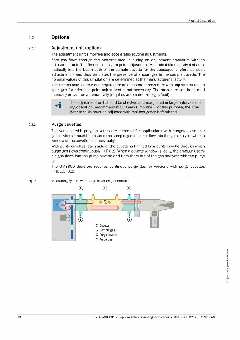
2.2.2 Purge cuvettesThe versions with purge cuvettes are intended for applications with dangerous samplegases where it must be ensured the sample gas does not flow into the gas analyzer when awindow of the cuvette becomes leaky.
With purge cuvettes, each side of the cuvette is flanked by a purge cuvette through whichpurge gas flows continuously (→ Fig. 2). When a cuvette window is leaky, the emerging sam-ple gas flows into the purge cuvette and from there out of the gas analyzer with the purgegas.
The GMS800 therefore requires continous purge gas for versions with purge cuvettes(→ p. 12, §3.2).
Fig. 2 Measuring system with purge cuvettes (schematic)
The adjustment unit should be checked and readjusted in larger intervals dur-ing operation (recommendation: Every 6 months). For this purpose, the Ana-lyzer module must be adjusted with real test gases beforehand.
N2
N2
C
S
XX
YY
C CuvetteS Sample gasX Purge cuvetteY Purge gas
10 UNOR-MULTOR · Supplementary Operating Instructions · 8013027 V 2.0 · © SICK AG
Installation Information
Subj
ect t
o ch
ange
with
out n
otic
e
UNOR-MULTOR
3 Installation Information
Sample gas feed
Purge gas feed for purge cuvettes
UNOR-MULTOR · Supplementary Operating Instructions · 8013027 V 2.0 · © SICK AG 11
Installation Information
Subj
ect t
o ch
ange
with
out n
otic
e
3 . 1 Sample gas feed▸ Observe the information on sample gas feed in the “Series GMS800” Operating Instruc-
tions.
3 . 2 Purge gas feed for purge cuvettesOnly valid for versions with purge cuvettes (option → p. 10, § 2.2.2 )
In versions with purge cuvettes, the GMS800 enclosure has additional “purge gas inlet”und “purge gas outlet” gas connections.
1 Install an external continuous purge gas supply for GMS800.
Suitable purge gas: Chemically neutral gas (inert gas) or gas mixture suitable for dilut-ing and transporting the measured gas without danger.
2 Feed the purge gas through the “purge gas inlet“ gas connection on the enclosure.
Allowable pressure and volume flow: → p. 25, §6.3.2
3 Install a gas line on the “purge gas outlet” through which the purge gas and emerged sample gas are reliably discharged.
▸ Lead the gas line to a safe position where emerged sample gas cannot create any danger.
▸ Recommendation: Attach appropriate warning signs to the gas line or gas outlet informing about the hazardousness of the sample gas.
Gas connections type and version → Supplementary Operating Instructions for Enclosure
12 UNOR-MULTOR · Supplementary Operating Instructions · 8013027 V 2.0 · © SICK AG
Functions in SOPAS ET
Subj
ect t
o ch
ange
with
out n
otic
e
UNOR-MULTOR
4 Functions in SOPAS ET
Operating functions in the PC program “SOPAS ET”
Menu tree
Explanations
● Instructions for the PC program “SOPAS ET” → User Information for the pro-gram
● Exemplary menu representations → Technical Information “Basic Control Unit (BCU)” (contains information for operating with SOPAS ET)
UNOR-MULTOR · Supplementary Operating Instructions · 8013027 V 2.0 · © SICK AG 13
Functions in SOPAS ET
Subj
ect t
o ch
ange
with
out n
otic
e
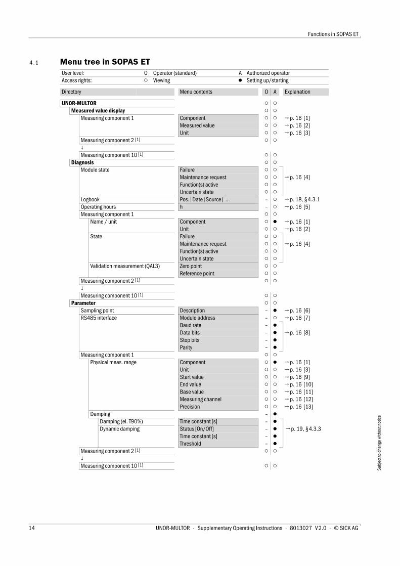
4 . 1 Menu tree in SOPAS ET User level: O Operator (standard) A Authorized operatorAccess rights: ○ Viewing ● Setting up/starting
Directory Menu contents O A Explanation
UNOR-MULTOR ○ ○Measured value display ○ ○
Measuring component 1 Component ○ ○ → p. 16 [1] Measured value ○ ○ → p. 16 [2] Unit ○ ○ → p. 16 [3]
Measuring component 2 [1] ○ ○↓Measuring component 10 [1] ○ ○
Diagnosis ○ ○Module state Failure ○ ○
Maintenance request ○ ○ → p. 16 [4]Function(s) active ○ ○Uncertain state ○ ○
Logbook Pos.|Date|Source| … – ○ → p. 18, §4.3.1Operating hours h – ○ → p. 16 [5]Measuring component 1 ○ ○
Name / unit Component ○ ● → p. 16 [1] Unit ○ ○ → p. 16 [2]
State Failure ○ ○ Maintenance request ○ ○ → p. 16 [4]Function(s) active ○ ○Uncertain state ○ ○
Validation measurement (QAL3) Zero point ○ ○Reference point ○ ○
Measuring component 2 [1] ○ ○↓Measuring component 10 [1] ○ ○
Parameter ○ ○Sampling point Description – ● → p. 16 [6] RS485 interface Module address – ○ → p. 16 [7]
Baud rate – ● Data bits – ● → p. 16 [8] Stop bits – ●Parity – ●
Measuring component 1 ○ ○Physical meas. range Component ○ ● → p. 16 [1]
Unit ○ ○ → p. 16 [3] Start value ○ ○ → p. 16 [9]End value ○ ○ → p. 16 [10]Base value ○ ○ → p. 16 [11]Measuring channel ○ ○ → p. 16 [12]Precision ○ ○ → p. 16 [13]
Damping – ●Damping (el. T90%) Time constant [s] – ● Dynamic damping Status [On/Off] – ● → p. 19, §4.3.3
Time constant [s] – ●Threshold – ●
Measuring component 2 [1] ○ ○↓Measuring component 10 [1] ○ ○
14 UNOR-MULTOR · Supplementary Operating Instructions · 8013027 V 2.0 · © SICK AG
Functions in SOPAS ET
Subj
ect t
o ch
ange
with
out n
otic
e
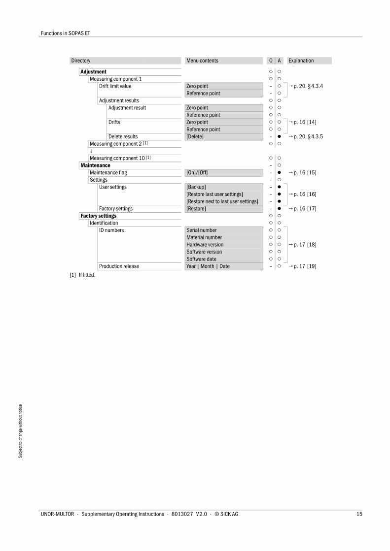
Adjustment ○ ○Measuring component 1 ○ ○
Drift limit value Zero point – ○ → p. 20, §4.3.4Reference point – ○
Adjustment results ○ ○Adjustment result Zero point ○ ○
Reference point ○ ○Drifts Zero point ○ ○ → p. 16 [14]
Reference point ○ ○Delete results [Delete] – ● → p. 20, §4.3.5
Measuring component 2 [1] ○ ○↓Measuring component 10 [1] ○ ○
Maintenance – ○Maintenance flag [On]/[Off] – ● → p. 16 [15] Settings – ○
User settings [Backup] – ●[Restore last user settings] – ● → p. 16 [16][Restore next to last user settings] – ●
Factory settings [Restore] – ● → p. 16 [17]Factory settings ○ ○
Identification ○ ○ID numbers Serial number ○ ○
Material number ○ ○Hardware version ○ ○ → p. 17 [18] Software version ○ ○Software date ○ ○
Production release Year | Month | Date – ○ → p. 17 [19]
[1] If fitted.
Directory Menu contents O A Explanation
UNOR-MULTOR · Supplementary Operating Instructions · 8013027 V 2.0 · © SICK AG 15
Functions in SOPAS ET
Subj
ect t
o ch
ange
with
out n
otic
e
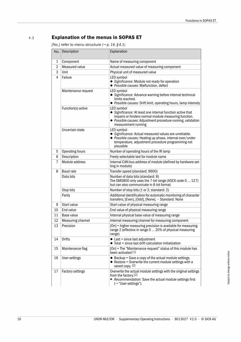
4 . 2 Explanation of the menus in SOPAS ET[No.] refer to menu structure (→ p. 14, § 4.1)
No. Description Explanation
1 Component Name of measuring component2 Measured value Actual measured value of measuring component3 Unit Physical unit of measured value4 Failure LED symbol
● Significance: Module not ready for operation● Possible causes: Malfunction, defect
Maintenance request LED symbol● Significance: Advance warning before internal technical
limits reached.● Possible causes: Drift limit, operating hours, lamp intensity
Function(s) active LED symbol● Significance: At least one internal function active that
impairs or hinders normal module measuring function.● Possible causes: Adjustment procedure running, validation
measurement runningUncertain state LED symbol
● Significance: Actual measured values are unreliable.● Possible causes: Heating up phase, internal over/under
temperature, adjustment procedure programming not plausible
5 Operating hours Number of operating hours of the IR lamp6 Description Freely selectable text for module name7 Module address Internal CAN bus address of module (defined by hardware set-
ting in module)8 Baud rate Transfer speed (standard: 9600)
Data bits Number of data bits (standard: 8)The GMS800 only uses the 7-bit range (ASCII code 0 … 127) but can also communicate in 8-bit format.
Stop bits Number of stop bits (1 or 2; standard: 2)Parity Additional identification for automatic monitoring of character
transfers; [Even], [Odd], [None]. – Standard: None9 Start value Start value of physical measuring range
10 End value End value of physical measuring range11 Base value Internal physical base value of measuring range 12 Measuring channel Internal measuring channel for measuring component 13 Precision [On] = higher measuring precision is available for measuring
range 2 (effective in range 0 … 20% of physical measuring range)
14 Drifts ● Last = since last adjustment● Total = since last drift calculation initialization
15 Maintenance flag [On] = The “Maintenance request” status of this module has been activated [1]
16 User settings ● Backup = Save a copy of the actual module settings.● Restore = Overwrite the current module settings with a
saved copy. [2]
17 Factory settings Overwrite the actual module settings with the original settings from the factory.[2]
▸ Recommendation: Save the actual module settings first (→ “User settings”).
16 UNOR-MULTOR · Supplementary Operating Instructions · 8013027 V 2.0 · © SICK AG
Functions in SOPAS ET
Subj
ect t
o ch
ange
with
out n
otic
e
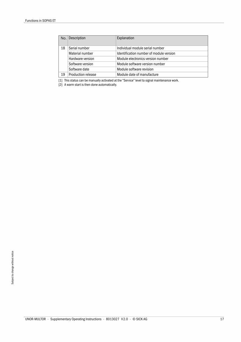
18 Serial number Individual module serial numberMaterial number Identification number of module versionHardware version Module electronics version numberSoftware version Module software version numberSoftware date Module software revision
19 Production release Module date of manufacture
[1] This status can be manually activated at the “Service” level to signal maintenance work.[2] A warm start is then done automatically.
No. Description Explanation
UNOR-MULTOR · Supplementary Operating Instructions · 8013027 V 2.0 · © SICK AG 17
Functions in SOPAS ET
Subj
ect t
o ch
ange
with
out n
otic
e
4 . 3 Explanation of functions
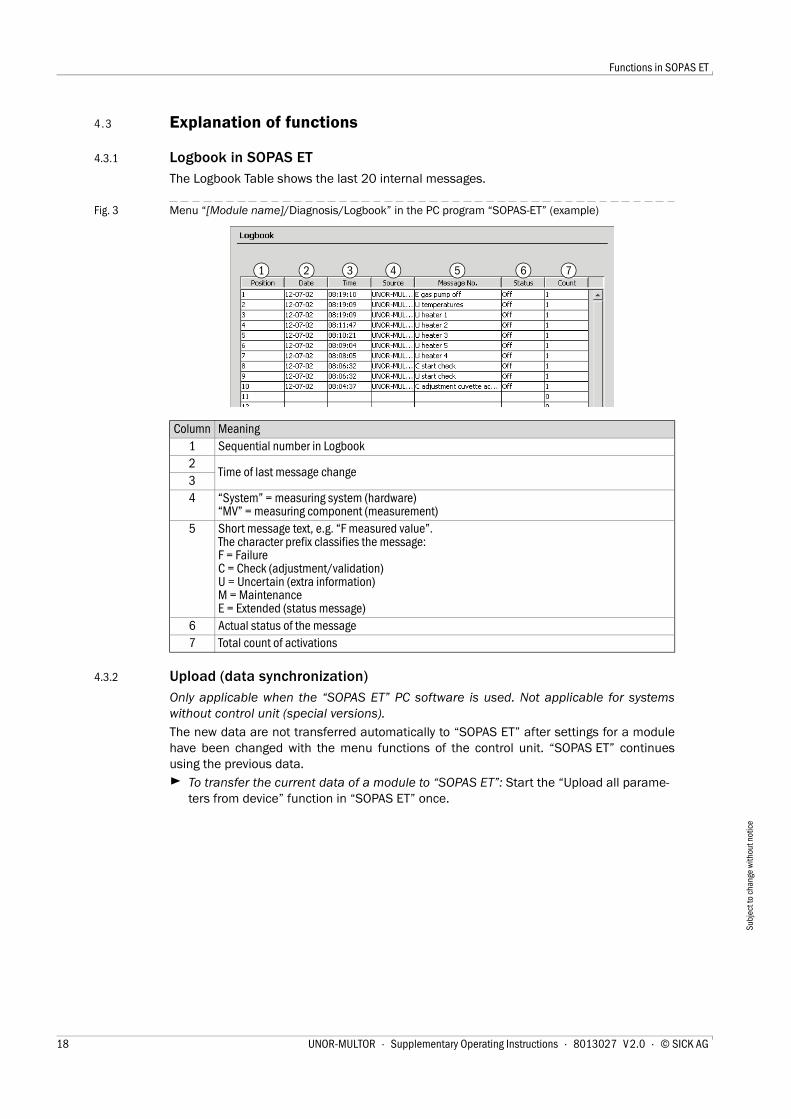
4.3.1 Logbook in SOPAS ETThe Logbook Table shows the last 20 internal messages.
Fig. 3 Menu “[Module name]/Diagnosis/Logbook” in the PC program “SOPAS-ET” (example)
4.3.2 Upload (data synchronization)Only applicable when the “SOPAS ET” PC software is used. Not applicable for systemswithout control unit (special versions).
The new data are not transferred automatically to “SOPAS ET” after settings for a modulehave been changed with the menu functions of the control unit. “SOPAS ET” continuesusing the previous data.
▸ To transfer the current data of a module to “SOPAS ET”: Start the “Upload all parame-ters from device” function in “SOPAS ET” once.
Column Meaning1 Sequential number in Logbook2
Time of last message change34 “System” = measuring system (hardware)
“MV” = measuring component (measurement) 5 Short message text, e.g. “F measured value”.
The character prefix classifies the message: F = FailureC = Check (adjustment/validation)U = Uncertain (extra information)M = MaintenanceE = Extended (status message)
6 Actual status of the message7 Total count of activations
1 2 3 4 5 6 7
18 UNOR-MULTOR · Supplementary Operating Instructions · 8013027 V 2.0 · © SICK AG
Functions in SOPAS ET
Subj
ect t
o ch
ange
with
out n
otic
e
4.3.3 Damping
Constant damping
When "damping" has been programmed, the average value from the current measuredvalue and the previous measured values (floating averaging) are displayed instead of thecurrent measured value.
Possible uses include:
– Damping metrological measured value fluctuations (noise)
– Smoothing fluctuating measured values when only the average value is relevant
Damping is done in the Analyzer module and therefore affects all measured value displaysand outputs. It is also active during an adjustment procedure.
Dynamic damping
“Dynamic damping” serves to compensate measured value fluctuations without signifi-cantly increasing the reaction time. Dynamic damping is automatically deactivated whenthe measured value changes rapidly and strongly as against “normal” damping. This allows“smoothing” continuous minor measured value fluctuations but rapid measured valuechanges are still displayed without delay. Dynamic behavior is determined with the “Thresh-old” parameter:
– When the measured values change only slowly, dynamic damping functions as constant damping.
– When the difference of successive measured values is greater than the set limit, dynamic damping is terminated automatically and remains disabled as long as the measured values continue to change rapidly.
– Dynamic damping is active again when measured value differences are below the limit again (which means measured values changes remain slight).
Dynamic damping also affects all measured value displays and outputs.
● Increasing damping normally increases the reaction time (90% time) of the gas analysis system accordingly.
● Reducing damping can possibly increase the measurement signal “noise” (measuring turbulence).
● Time constant = 0 s means: No damping.
CAUTION: Risk of incorrect adjustmentThe “Measuring time, test gas” must be at least 150% of the set damping time constant during adjustments.▸ When damping has been reset or increased: Check whether adjustment
settings need to be adapted.
UNOR-MULTOR · Supplementary Operating Instructions · 8013027 V 2.0 · © SICK AG 19
Functions in SOPAS ET
Subj
ect t
o ch
ange
with
out n
otic
e
4.3.4 Drift limit values
Purpose
Analyzer module drifts are caused, for example, by contamination, mechanical changes oraging effects. The total drift (i.e. the deviation from original state) increases gradually. It isnot practical to keep compensating an ever increasing total drift through computation.Inspect and reset the Analyzer module when total drift has become very large.
Drift limit values monitor total drift automatically. These also protect against erroneousadjustments.
Functionality
After every adjustment, an Analyzer module compares the calculated total drift with thedrift limit value. Drift limit value violation is reported in two stages:
● Status “M” (Maintenance request) is activated when the total drift reaches 100 … 120% of the drift limit value.
● Status “F” (Failure) is activated when the total drift reaches more than 120% of the drift limit value.
● When an adjustment procedure shows that a calculated drift has reached more than 150% of the drift limit value, the result from this adjustment procedure is ignored and the previous adjustment remains valid.
4.3.5 Deleting adjustment results The “Delete results” function deletes all determined drift values of a measuring compo-nent. Drift limit values then refer to new drift values.
The data of the previous adjustment which was performed before are then no longer dis-played. Test gas settings (e. g. nominal value) are not changed.
● The drift limit values are set in the factory (standard value: 10%).● A Service function is available to reset all drift values to “0” (Drift reset).
This is useful after Analyzer module maintenance when this has estab-lished a new original state.
CAUTION: Risk of incorrect adjustmentIf very large drift values are displayed after a manual adjustment procedure (→ Operating Instructions “Basic Control Unit (BCU)”), a test gas used probably did not match the relevant test gas setting or gas feed was interrupted – and the adjustment result was still accepted.▸ Do not delete incorrect adjustment results, but repeat the adjustment care-
fully.
▸ Do not use the deletion of adjustment results to nullify large drift values caused by extensive physical changes of an Analyzer module. Instead, clean the Analyzer module or perform an adjustment.[1]
▸ After an Analyzer module has been cleaned, altered or exchanged: Delete the relevant adjustment results and perform an adjustment.
[1] By the manufacturer's Customer Service or authorized skilled persons with appropriate training.
20 UNOR-MULTOR · Supplementary Operating Instructions · 8013027 V 2.0 · © SICK AG
Adjustment Information
Subj
ect t
o ch
ange
with
out n
otic
e
UNOR-MULTOR
5 Adjustment Information
Parameter setting
Control
Adjustment interval
Special H2O adjustment
UNOR-MULTOR · Supplementary Operating Instructions · 8013027 V 2.0 · © SICK AG 21
Adjustment Information
Subj
ect t
o ch
ange
with
out n
otic
e
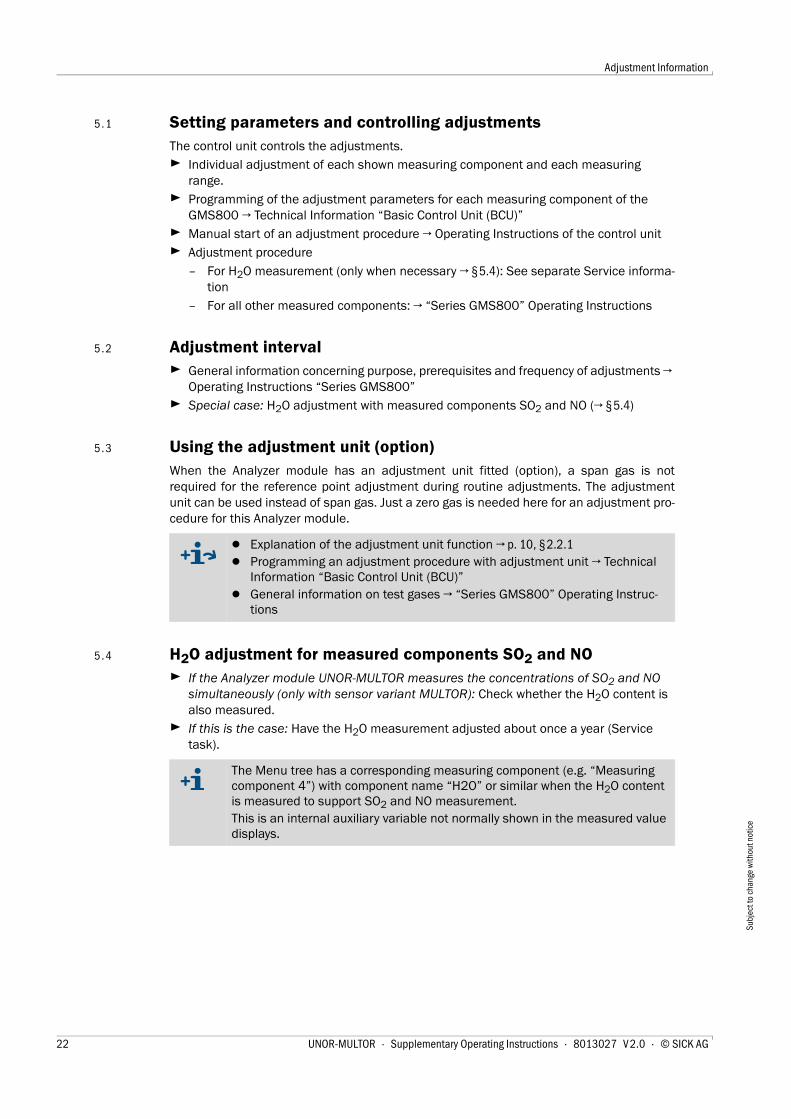
5 . 1 Setting parameters and controlling adjustmentsThe control unit controls the adjustments.
▸ Individual adjustment of each shown measuring component and each measuring range.
▸ Programming of the adjustment parameters for each measuring component of the GMS800 → Technical Information “Basic Control Unit (BCU)”
▸ Manual start of an adjustment procedure → Operating Instructions of the control unit
▸ Adjustment procedure
– For H2O measurement (only when necessary → §5.4): See separate Service informa-tion
– For all other measured components: → “Series GMS800” Operating Instructions
5 . 2 Adjustment interval▸ General information concerning purpose, prerequisites and frequency of adjustments →
Operating Instructions “Series GMS800”
▸ Special case: H2O adjustment with measured components SO2 and NO (→ §5.4)
5 . 3 Using the adjustment unit (option)When the Analyzer module has an adjustment unit fitted (option), a span gas is notrequired for the reference point adjustment during routine adjustments. The adjustmentunit can be used instead of span gas. Just a zero gas is needed here for an adjustment pro-cedure for this Analyzer module.
5 . 4 H2O adjustment for measured components SO2 and NO▸ If the Analyzer module UNOR-MULTOR measures the concentrations of SO2 and NO
simultaneously (only with sensor variant MULTOR): Check whether the H2O content is also measured.
▸ If this is the case: Have the H2O measurement adjusted about once a year (Service task).
● Explanation of the adjustment unit function → p. 10, §2.2.1● Programming an adjustment procedure with adjustment unit → Technical
Information “Basic Control Unit (BCU)”● General information on test gases → “Series GMS800” Operating Instruc-
tions
The Menu tree has a corresponding measuring component (e.g. “Measuring component 4”) with component name “H2O” or similar when the H2O content is measured to support SO2 and NO measurement.This is an internal auxiliary variable not normally shown in the measured value displays.
22 UNOR-MULTOR · Supplementary Operating Instructions · 8013027 V 2.0 · © SICK AG
Technical Data
Subj
ect t
o ch
ange
with
out n
otic
e
UNOR-MULTOR
6 Technical Data
Ambient conditions
Sample gas specifications
Metrological specifications
UNOR-MULTOR · Supplementary Operating Instructions · 8013027 V 2.0 · © SICK AG 23
Technical Data
Subj
ect t
o ch
ange
with
out n
otic
e
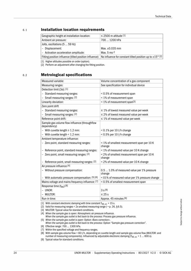
6 . 1 Installation location requirements
6 . 2 Metrological specifications
Geographic height at installation location: ≤ 2500 m altitude [1]
[1] Higher altitudes possible on order (option).
Ambient air pressure: 700 … 1200 hPaJolts, oscillations (5 … 59 Hz)– Displacement: Max. ±0.035 mm– Activation acceleration amplitude: Max. 5 ms-2
Fitting position influence (tilted position influence) No influence for constant tilted position up to ±15° [2]
[2] Perform an adjustment after changing the fitting position.
Measured variable: Volume concentration of a gas componentMeasuring ranges: See specification for individual deviceDetection limit (3σ): [1]
[1] With constant electronic damping with time constant T90, el. = 15 s.
– Standard measuring ranges: < 0.5% of measurement span – Small measuring ranges: [2]
[2] Valid for measuring ranges < 2x smallest measuring range (→ p. 26, §6.5).
< 1% of measurement span Linearity deviation: < 1% of measurement span[3]
[3] MULTOR: Typical value for standard conditions.
Zero point drift– Standard measuring ranges: ≤ 1% of lowest measured value per week– Small measuring ranges: [2] ≤ 2% of lowest measured value per weekReference point drift: ≤ 1% of measured value per weekSample gas volume flow influence (throughflow dependency)– With cuvette length ≥ 1.2 mm: < 0.1% per 10 l/h change– With cuvette length < 1.2 mm: < 0.5% per 10 l/h changeAmbient temperature influence:– Zero point, standard measuring ranges: < 1% of smallest measurement span per 10 K
change– Reference point, standard measuring ranges: < 1% of measured value per 10 K change– Zero point, small measuring ranges: [2] < 2% of smallest measurement span per 10 K
change– Reference point, small measuring ranges: [2] < 2% of measured value per 10 K changeAir pressure influence [4]
[4] When the sample gas is open: Atmospheric air pressure influence.When the sample gas outlet is fed back to the process: Process gas pressure influence.
– Without pressure compensation: 0.5 … 1.0% of measured value per 1% pressure change
– With automatic pressure compensation: [5] [6]
[5] When the sample gas outlet is open: Option »Baro correction«. When the sample gas outlet is fed back to the process: Option “Sample gas pressure correction”.
[6] Effective range: 700 … 1300 hPa.
< 01% of measured value per 1% pressure changeMains voltage and mains frequency influence: [7]
[7] Within the specified voltage and frequency ranges.
< 0.5% of smallest measurement spanResponse time (t90) [8]
[8] With sample gas volume flow = 60 l/h, depending on cuvette length and sample gas volume flow (MULTOR: and number of measuring components). Influenced by adjustable electronic damping (T90, el. = 1 … 600 s).
– UNOR: 3 s [9]
[9] Typical value for standard conditions.
– MULTOR: ≤ 25 sRun-in time: Approx. 45 minutes [9]
24 UNOR-MULTOR · Supplementary Operating Instructions · 8013027 V 2.0 · © SICK AG
Technical Data
Subj
ect t
o ch
ange
with
out n
otic
e
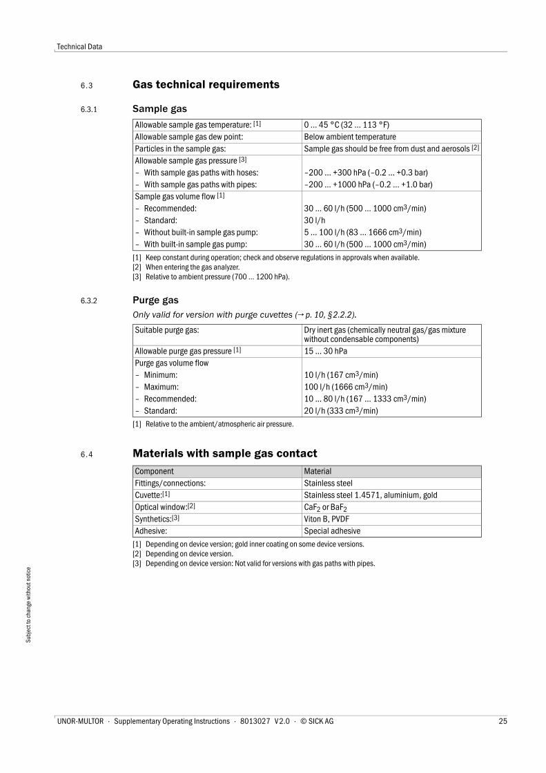
6 . 3 Gas technical requirements
6.3.1 Sample gas
6.3.2 Purge gasOnly valid for version with purge cuvettes (→ p. 10, §2.2.2).
6 . 4 Materials with sample gas contact
Allowable sample gas temperature: [1]
[1] Keep constant during operation; check and observe regulations in approvals when available.
0 … 45 °C (32 … 113 °F)Allowable sample gas dew point: Below ambient temperatureParticles in the sample gas: Sample gas should be free from dust and aerosols [2]
[2] When entering the gas analyzer.
Allowable sample gas pressure [3]
[3] Relative to ambient pressure (700 … 1200 hPa).
– With sample gas paths with hoses: –200 … +300 hPa (–0.2 … +0.3 bar)– With sample gas paths with pipes: –200 … +1000 hPa (–0.2 … +1.0 bar)Sample gas volume flow [1]
– Recommended: 30 … 60 l/h (500 … 1000 cm3/min)– Standard: 30 l/h– Without built-in sample gas pump: 5 … 100 l/h (83 … 1666 cm3/min)– With built-in sample gas pump: 30 … 60 l/h (500 … 1000 cm3/min)
Suitable purge gas: Dry inert gas (chemically neutral gas/gas mixture without condensable components)
Allowable purge gas pressure [1]
[1] Relative to the ambient/atmospheric air pressure.
15 … 30 hPaPurge gas volume flow– Minimum: 10 l/h (167 cm3/min)– Maximum: 100 l/h (1666 cm3/min)– Recommended: 10 … 80 l/h (167 … 1333 cm3/min)– Standard: 20 l/h (333 cm3/min)
Component MaterialFittings/connections: Stainless steelCuvette:[1]
[1] Depending on device version; gold inner coating on some device versions.
Stainless steel 1.4571, aluminium, goldOptical window:[2]
[2] Depending on device version.
CaF2 or BaF2 Synthetics:[3]
[3] Depending on device version: Not valid for versions with gas paths with pipes.
Viton B, PVDFAdhesive: Special adhesive
UNOR-MULTOR · Supplementary Operating Instructions · 8013027 V 2.0 · © SICK AG 25
Technical Data
Subj
ect t
o ch
ange
with
out n
otic
e
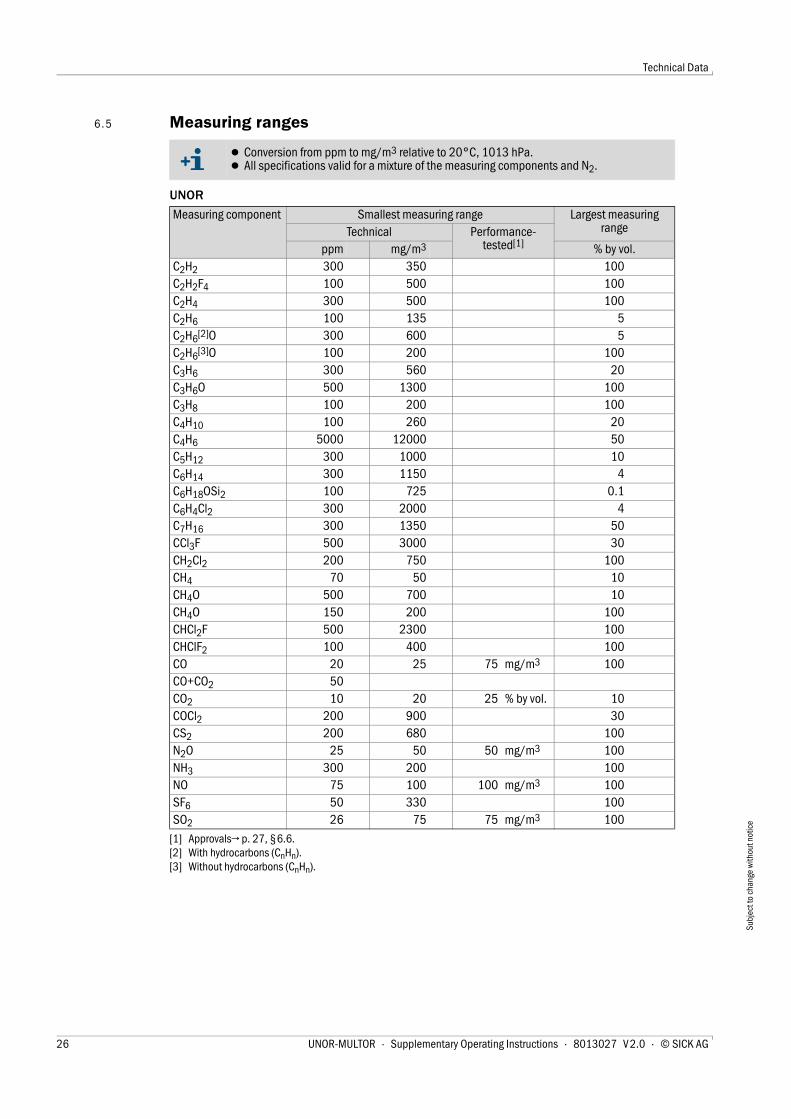
6 . 5 Measuring ranges
UNOR
● Conversion from ppm to mg/m3 relative to 20°C, 1013 hPa.● All specifications valid for a mixture of the measuring components and N2.
Measuring component Smallest measuring range Largest measuring rangeTechnical Performance-
tested[1]
[1] Approvals→ p. 27, §6.6.
ppm mg/m3 % by vol.C2H2 300 350 100C2H2F4 100 500 100C2H4 300 500 100C2H6 100 135 5C2H6[2]O
[2] With hydrocarbons (CnHn).
300 600 5C2H6[3]O
[3] Without hydrocarbons (CnHn).
100 200 100C3H6 300 560 20C3H6O 500 1300 100C3H8 100 200 100C4H10 100 260 20C4H6 5000 12000 50C5H12 300 1000 10C6H14 300 1150 4C6H18OSi2 100 725 0.1C6H4Cl2 300 2000 4C7H16 300 1350 50CCl3F 500 3000 30CH2Cl2 200 750 100CH4 70 50 10CH4O 500 700 10CH4O 150 200 100CHCl2F 500 2300 100CHClF2 100 400 100CO 20 25 75 mg/m3 100CO+CO2 50CO2 10 20 25 % by vol. 10COCl2 200 900 30CS2 200 680 100N2O 25 50 50 mg/m3 100NH3 300 200 100NO 75 100 100 mg/m3 100SF6 50 330 100SO2 26 75 75 mg/m3 100
26 UNOR-MULTOR · Supplementary Operating Instructions · 8013027 V 2.0 · © SICK AG
Technical Data
Subj
ect t
o ch
ange
with
out n
otic
e
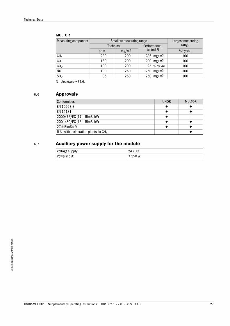
MULTOR
6 . 6 Approvals
6 . 7 Auxiliary power supply for the module
Measuring component Smallest measuring range Largest measuring rangeTechnical Performance-
tested[1]
[1] Approvals → §6.6.
ppm mg/m3 % by vol.CH4 280 200 286 mg/m3 100CO 160 200 200 mg/m3 100CO2 100 200 25 % by vol. 100NO 190 250 250 mg/m3 100SO2 85 250 250 mg/m3 100
Conformities UNOR MULTOREN 15267-3 ● ●EN 14181 ● ●2000/76/EC (17th BImSchV) ● –2001/80/EC (13th BImSchV) ● ●27th BImSchV ● ●TI Air with incineration plants for CH4 – ●
Voltage supply: 24 VDCPower input: ≤ 150 W
UNOR-MULTOR · Supplementary Operating Instructions · 8013027 V 2.0 · © SICK AG 27
Index
Keywords
AAdjustment- Adjustment interval . . . . . . . . . . . . . . . . . . . . . . . . 22- Adjustment procedure (information) . . . . . . . . . . 22- Adjustment unit, using . . . . . . . . . . . . . . . . . . . . . . 22- Parameter settings/settings . . . . . . . . . . . . . . . . . 22
Adjustment result . . . . . . . . . . . . . . . . . . . . . . . . . . . 15Adjustment results . . . . . . . . . . . . . . . . . . . . . . . . . . 15Adjustment unit . . . . . . . . . . . . . . . . . . . . . . . . . . . . . 10Approvals . . . . . . . . . . . . . . . . . . . . . . . . . . . . . . . . . . 27Auxiliary power supply . . . . . . . . . . . . . . . . . . . . . . . . 27
BBackup (user settings) . . . . . . . . . . . . . . . . . . . . . . . 15Backup copy (user settings) . . . . . . . . . . . . . . . . . . . 15Base value (display) . . . . . . . . . . . . . . . . . . . . . . . . . 16Baud rate . . . . . . . . . . . . . . . . . . . . . . . . . . . . . . . . . . 16
CConformities . . . . . . . . . . . . . . . . . . . . . . . . . . . . . . . . 27Constant damping . . . . . . . . . . . . . . . . . . . . . . . . . . . 19
DDamping- Constant damping (el. T90%) . . . . . . . . . . . . . . . . 19- Dynamic damping . . . . . . . . . . . . . . . . . . . . . 14, 19- el. T90% (constant damping) . . . . . . . . . . . . . . . . 14
Data bits . . . . . . . . . . . . . . . . . . . . . . . . . . . . . . . . . . . 16Detection limit . . . . . . . . . . . . . . . . . . . . . . . . . . . . . . 24Diagnosis . . . . . . . . . . . . . . . . . . . . . . . . . . . . . . . . . . 14Drift- Specifications . . . . . . . . . . . . . . . . . . . . . . . . . . . . . 24- Viewing actual values . . . . . . . . . . . . . . . . . . . . . . 15- Viewing drift limit values . . . . . . . . . . . . . . . . . . . . 15
Drift limit values . . . . . . . . . . . . . . . . . . . . . . . . . . . . . 20Dynamic damping . . . . . . . . . . . . . . . . . . . . . . . 14, 19
Eel. T90% (constant damping)- Explanation . . . . . . . . . . . . . . . . . . . . . . . . . . . . . . . 19- Menu function . . . . . . . . . . . . . . . . . . . . . . . . . . . . 14
End value (display) . . . . . . . . . . . . . . . . . . . . . . . . . . 16
FFailure . . . . . . . . . . . . . . . . . . . . . . . . . . . . . . . . . . . . 16Flow (volume flow)- Purge gas . . . . . . . . . . . . . . . . . . . . . . . . . . . . . . . . 25- Sample gas . . . . . . . . . . . . . . . . . . . . . . . . . . . . . . . 25
Function(s) active . . . . . . . . . . . . . . . . . . . . . . . . . . . 16
GGlossary . . . . . . . . . . . . . . . . . . . . . . . . . . . . . . . . . . . . 2
HHardware version (display) . . . . . . . . . . . . . . . . . . . . 15
IID numbers . . . . . . . . . . . . . . . . . . . . . . . . . . . . . . . . 15Identification . . . . . . . . . . . . . . . . . . . . . . . . . . . . . . . 15Information symbols . . . . . . . . . . . . . . . . . . . . . . . . . . 2Installation information . . . . . . . . . . . . . . . . . . . . . . . 11
LLogbook . . . . . . . . . . . . . . . . . . . . . . . . . . . . . . . 14, 18
MMaintenance flag . . . . . . . . . . . . . . . . . . . . . . . . . . . . 15Maintenance request . . . . . . . . . . . . . . . . . . . . . . . . 16Material number . . . . . . . . . . . . . . . . . . . . . . . . . . . . 15Materials . . . . . . . . . . . . . . . . . . . . . . . . . . . . . . . . . . 25Measured value display- Constant damping . . . . . . . . . . . . . . . . . . . . . . . . . 19- Dynamic damping . . . . . . . . . . . . . . . . . . . . . . . . . 19- In SOPAS ET . . . . . . . . . . . . . . . . . . . . . . . . . . . . . . 14
Measuring channel (display) . . . . . . . . . . . . . . . . . . 16Measuring components- Display name and physical unit . . . . . . . . . . . . . . 14- Displaying physical measuring ranges . . . . . . . . . 14- Measuring ranges . . . . . . . . . . . . . . . . . . . . . . . . . 26- Show status . . . . . . . . . . . . . . . . . . . . . . . . . . . . . . 14
Measuring principle . . . . . . . . . . . . . . . . . . . . . . . . . . . 9Measuring ranges- Specifications . . . . . . . . . . . . . . . . . . . . . . . . . . . . . 26
Measuring system . . . . . . . . . . . . . . . . . . . . . . . . . . . . 9Menu functions . . . . . . . . . . . . . . . . . . . . . . . . . . . . . 13Menu tree . . . . . . . . . . . . . . . . . . . . . . . . . . . . . . . . . . 14Module address . . . . . . . . . . . . . . . . . . . . . . . . . . . . . 16Module state . . . . . . . . . . . . . . . . . . . . . . . . . . . . . . . 14MULTOR- Description . . . . . . . . . . . . . . . . . . . . . . . . . . . . . . . . 9- Measuring ranges . . . . . . . . . . . . . . . . . . . . . . . . . 27
NName (sampling point) . . . . . . . . . . . . . . . . . . . . . . . 16
OMeasuring range 2 . . . . . . . . . . . . . . . . . . . . . . . . . . 14Operating hours . . . . . . . . . . . . . . . . . . . . . . . . . . . . . 14Options . . . . . . . . . . . . . . . . . . . . . . . . . . . . . . . . . . . . 10
28 UNOR-MULTOR · Supplementary Operating Instructions · 8013027 V 2.0 · © SICK AG
Index
PParity . . . . . . . . . . . . . . . . . . . . . . . . . . . . . . . . . . . . . 16Power input . . . . . . . . . . . . . . . . . . . . . . . . . . . . . . . . 27Precision (display) . . . . . . . . . . . . . . . . . . . . . . . . . . . 16Pressure- Purge gas . . . . . . . . . . . . . . . . . . . . . . . . . . . . . . . . 25- Sample gas . . . . . . . . . . . . . . . . . . . . . . . . . . . . . . 25
Product description . . . . . . . . . . . . . . . . . . . . . . . . . . 7Production release . . . . . . . . . . . . . . . . . . . . . . . . . . 15Purge cuvettes- Description . . . . . . . . . . . . . . . . . . . . . . . . . . . . . . . 10- Purge gas feed . . . . . . . . . . . . . . . . . . . . . . . . . . . . 12
Purge gas- Connections, feed . . . . . . . . . . . . . . . . . . . . . . . . . 12- Purpose (purge cuvette) . . . . . . . . . . . . . . . . . . . . 10- Specifications . . . . . . . . . . . . . . . . . . . . . . . . . . . . 25
QQAL3 . . . . . . . . . . . . . . . . . . . . . . . . . . . . . . . . . . . . . 14
RRestoring factory settings . . . . . . . . . . . . . . . . . . . . 15RS485 interface . . . . . . . . . . . . . . . . . . . . . . . . . . . . 14
SSafety information- Drift reset . . . . . . . . . . . . . . . . . . . . . . . . . . . . . . . . 20
Sample gas- Materials with sample gas contact . . . . . . . . . . . 25- Specifications . . . . . . . . . . . . . . . . . . . . . . . . . . . . 25
Sample gas feed- General . . . . . . . . . . . . . . . . . . . . . . . . . . . . . . . . . . 12
Serial number . . . . . . . . . . . . . . . . . . . . . . . . . . . . . . 15Settings . . . . . . . . . . . . . . . . . . . . . . . . . . . . . . . . . . . 15Settings, back up/restore . . . . . . . . . . . . . . . . . . . . 15Signal words . . . . . . . . . . . . . . . . . . . . . . . . . . . . . . . . 2Software date . . . . . . . . . . . . . . . . . . . . . . . . . . . . . . 15Software version . . . . . . . . . . . . . . . . . . . . . . . . . . . . 15SOPAS ET (important information) . . . . . . . . . . . . . 18Start value (display) . . . . . . . . . . . . . . . . . . . . . . . . . 16Stop bits . . . . . . . . . . . . . . . . . . . . . . . . . . . . . . . . . . 16Symbols (explanation) . . . . . . . . . . . . . . . . . . . . . . . . 2
TTechnical data . . . . . . . . . . . . . . . . . . . . . . . . . . . . . 23- Materials with sample gas contact . . . . . . . . . . . 25- Measuring ranges . . . . . . . . . . . . . . . . . . . . . . . . . 26- Metrological specifications . . . . . . . . . . . . . . . . . . 24- Power input . . . . . . . . . . . . . . . . . . . . . . . . . . . . . . 27- Technical gas specifications . . . . . . . . . . . . . . . . . 25- Voltage supply . . . . . . . . . . . . . . . . . . . . . . . . . . . . 27
Temperature- Purge gas . . . . . . . . . . . . . . . . . . . . . . . . . . . . . . . . 25- Sample gas . . . . . . . . . . . . . . . . . . . . . . . . . . . . . . 25
Threshold (dynamic damping) . . . . . . . . . . . . . . . . . 14Time constant- el. T90% (constant damping) . . . . . . . . . . . . . . . . 14- for dynamic damping . . . . . . . . . . . . . . . . . . . . . . 14
UUncertain state . . . . . . . . . . . . . . . . . . . . . . . . . . . . . 16UNOR- Description . . . . . . . . . . . . . . . . . . . . . . . . . . . . . . . . 9- Measuring ranges . . . . . . . . . . . . . . . . . . . . . . . . . 26
Upload all parameters from device . . . . . . . . . . . . . 18User settings, back up/restore . . . . . . . . . . . . . . . . 15
VValidation measurement (result) . . . . . . . . . . . . . . . 14Voltage supply . . . . . . . . . . . . . . . . . . . . . . . . . . . . . . 27Volume flow- Purge gas . . . . . . . . . . . . . . . . . . . . . . . . . . . . . . . . 25- Sample gas . . . . . . . . . . . . . . . . . . . . . . . . . . . . . . 25
WWarning symbols, warning levels . . . . . . . . . . . . . . . 2
UNOR-MULTOR · Supplementary Operating Instructions · 8013027 V 2.0 · © SICK AG 29
SICK AG | Waldkirch | Germany | www.sick.com
8013
027/
V2.0
/201
2-12
|Su
bjec
t to
chan
ge w
ithou
t not
ice SICK worldwide
You will find our local subsidiary
or agency at:
www.sick.com
Your local sales and service partner
UNOR-MULTOR


