29
AnchorZip10 0712-SOM-00001, Issue: 03 1 © Tritech International Ltd. AnchorZip10 Product Manual 0712-SOM-00001, Issue: 03

AnchorZip10
0712-SOM-00001, Issue: 03 1 © Tritech International Ltd.
AnchorZip10
Product Manual
0712-SOM-00001, Issue: 03

AnchorZip10
0712-SOM-00001, Issue: 03 2 © Tritech International Ltd.
© Tritech International Ltd
The copyright in this document is the property of Tritech International Ltd. The document is supplied by Tritech International Ltd onthe understanding that it may not be copied, used, or disclosed to others except as authorised in writing by Tritech International Ltd.
Tritech International Ltd reserves the right to change, modify and update designs and specifications as part of their ongoingproduct development programme.
All product names are trademarks of their respective companies.

AnchorZip10
0712-SOM-00001, Issue: 03 3 © Tritech International Ltd.
Table of ContentsHelp & Support ............................................................................................ 4Warning Symbols ........................................................................................ 51. Introduction .............................................................................................. 62. Specification ............................................................................................ 73. Installation ............................................................................................... 9
3.1. Mechanical .................................................................................... 93.2. Water Hose ................................................................................... 93.3. Hydraulic ..................................................................................... 10
4. Operation ............................................................................................... 144.1. Seating the Anchor ..................................................................... 144.2. Suction Pressures in Shallow Water .......................................... 154.3. Testing in Air .............................................................................. 17
5. Maintenance .......................................................................................... 185.1. Pre-dive ....................................................................................... 185.2. Storage ........................................................................................ 185.3. Dismantling and Reassembly ..................................................... 19
6. Troubleshooting ..................................................................................... 26A. Motor Protector Assembly Procedure .................................................. 27B. Performance Curves ............................................................................. 29

AnchorZip10
0712-SOM-00001, Issue: 03 4 © Tritech International Ltd.
Help & SupportFirst please read this manual thoroughly (particularly the Troubleshootingsection, if present). If a warranty is applicable, further details can be found inthe Warranty Statement, 0080-STF-00139, available upon request.
Tritech International Ltd can be contacted as follows:
Mail Tritech International LtdPeregrine RoadWesthill Business ParkWesthill, AberdeenshireAB32 6JL, UK
Telephone ++44(0)1224 744 111
Fax ++44(0)1224 741 771
Email [email protected]
Website www.tritech.co.uk
Prior to contacting Tritech International Ltd please ensure that the followingis available:
1. The Serial Numbers of the product and any Tritech International Ltd equipment connecteddirectly or indirectly to it.
2. Software or firmware revision numbers.
3. A clear fault description.
4. Details of any remedial action implemented.
!Contamination
If the product has been used in a contaminated or hazardousenvironment you must de-contaminate the product and reportany hazards prior to returning the unit for repair. Under nocircumstances should a product be returned that is contaminatedwith radioactive material.
The name of the organisation which purchased the system is held on recordat Tritech International Ltd and details of new software or hardware packageswill be announced at regular intervals. This manual may not detail everyaspect of operation and for the latest revision of the manual please refer towww.tritech.co.uk
Tritech International Ltd can only undertake to provide software support ofsystems loaded with the software in accordance with the instructions given inthis manual. It is the customer's responsibility to ensure the compatibility ofany other package they choose to use.

AnchorZip10
0712-SOM-00001, Issue: 03 5 © Tritech International Ltd.
Warning SymbolsThroughout this manual the following symbols may be used where applicableto denote any particular hazards or areas which should be given specialattention:
Note
This symbol highlights anything which would be of particularinterest to the reader or provides extra information outside of thecurrent topic.
Important
When this is shown there is potential to cause harm to thedevice due to static discharge. The components should not behandled without appropriate protection to prevent such a dischargeoccurring.
!Caution
This highlights areas where extra care is needed to ensure thatcertain delicate components are not damaged.
!Warning
DANGER OF INJURY TO SELF OR OTHERS
Where this symbol is present there is a serious risk of injury orloss of life. Care should be taken to follow the instructions correctlyand also conduct a separate Risk Assessment prior to commencingwork.

AnchorZip10
0712-SOM-00001, Issue: 03 6 © Tritech International Ltd.
1. IntroductionThe AnchorZip10 is designed as a high efficiency water pump for movinglarge quantities of water at relatively low pressures. Its main application is inthe deployment and retrieval of suction anchors and piles.
The AnchorZip10 has been designed to close couple to a flange plate toprovide the minimum of flow restrictions. Switching the flow from suction toblowing is achieved by sliding the whole pump and motor body.
The AnchorZip10 also incorporates a suction break relief valve which, on thelatest version, can be preset for pressures between 0.81 and 9.27 bar.

AnchorZip10
0712-SOM-00001, Issue: 03 7 © Tritech International Ltd.
2. Specification
452
315
Not to scale, dimensions in mm.
290
110
Ø72
4 off M16 x 2 on a 150mm PCD
!Warning
Never use the same size fitting for pressure hoses and the case drain. Ifthis is done there is significant risk of incorrect hook-up which will lead topressure being applied to the motor casing and could result in an explosionand personal injury.
Hydraulic Motor InputPressure 276 Bar (4000 psi)Flow 70 litres/minute (15 gpm)
Weight and MaterialsWeight in air 30kg (66lbs)Weight in water 14kg (31lbs)Materials Stainless Steel, Nylacast, UHMWPE
Actuator InputMin. pressure 70 Bar (1000 psi)Max. pressure 240 Bar (3480 psi)
Hydraulic FittingsMotor A & B No. 12 JIC maleMotor case drain No. 6 JIC maleActuator Connection No. 4 JIC male

Specification AnchorZip10
0712-SOM-00001, Issue: 03 8 © Tritech International Ltd.
OutputTypical differentialpressure
Up to 9.5 Bar (140 psi)
Typical suction flow Up to 80 cubic metres/hour at 7.5 Bar
Nozzle and Hose DimensionsAnchor portconnection
Square flange with 72mm port
Minimum hosediameter
72mm (2.8")
Check ValveNorm. Tritech Volvo Protector Assembly.Alt. Integrated Hydraulics FPR-1/22-0.5 (cracking pressure
50kPa)

AnchorZip10
0712-SOM-00001, Issue: 03 9 © Tritech International Ltd.
3. Installation
!Warning
Do not power the pump or hydraulic valve actuators until all hosesare properly connected to the pump.
There is a serious risk of injury to fingers if inserted into either thepower water intake or the pump delivery port.
If undertaking any testing operations suitable guards and othersafety measures must be in place.
3.1. Mechanical
The pump may be mounted in any orientation on the vehicle, but it isrecommended that the connection to the anchor be as direct and short aspossible to avoid inhibiting the flow. The mounting flange must be strongenough to carry the full weight of the pump.
The face of the pump carries 4 M16x2.0 mounting holes on a 150mm PCD.The pump mounting face is flat and the mating flange can either carry an o-ring or flat gasket. An o-ring seal groove is cut into the material for operatingat higher pressures.
Thread engagement should be between 45mm and 48mm (maximum) andtightening torque should be in the range 45-55Nm (33-40lbf·ft). Copper slip orsimilar grease should be used. Grade 70 or higher bolts are recommended.
Sufficient space should be allowed to permit the pump body including motorto slide through a distance of 110mm to switch between suction and blowing.
3.2. Water Hose
It is recommended that the pump is close coupled to the anchor by a directflange fitting or short sections of hard hose. Any flexible hose used must besuitable rated for the expected pressure differentials. Large diameter flexiblehose is liable to collapse under suction.

Installation AnchorZip10
0712-SOM-00001, Issue: 03 10 © Tritech International Ltd.
3.3. Hydraulic
Oil
The pump should be operated using a premium grade mineral basedhydraulic oil of ISO VG 22 to 32.
Filtration
The hydraulic system filtration must be to a minimum of 10μm absolutestandard. A 10μm nominal standard is regarded as inadequate.
The recommended filtration is UN elements produced by Pall IndustrialHydraulics Ltd. or equivalent products.
Hydraulic Hookup
RETURN
PRESSURE
B
A
C
Extend = Blow Retract = Suck
Figure 3.1. Hydraulic Hook-up Orientation

Installation AnchorZip10
0712-SOM-00001, Issue: 03 11 © Tritech International Ltd.
Note
If mounting restrictions dictate it is possible to rebuild the pumpwith "retract=blow" and "extend=suck". If required contact TritechInternational Ltd Technical Support for more details.
Fittings
The standard fittings for the motor are detailed in Chapter 2, Specification.
The pump suction/blow selection is achieved by two hydraulic cylinders thatmust be connected in parallel from a single control valve. The cylinder bodiesmove with the pump body and flexible hoses are required.

Installation AnchorZip10
0712-SOM-00001, Issue: 03 12 © Tritech International Ltd.
The pump is configured for correct rotation when the hydraulic supply isconnected to the "A" port of the Volvo motor and the return line to the "B"port (the impeller will not turn running in the reverse direction when a TritechVolvo Protector is fitted).
Figure 3.2. Motor viewed when fitted to AnchorZip10 with hydraulicfittings downwards
In order to avoid pressure losses it is mandatory that a minimum of ½ inchbore pipework or hoses are used on the flow and return lines to the motor.¾ inch or higher is recommended.
The drain line should not be connected to any return flow lines.

Installation AnchorZip10
0712-SOM-00001, Issue: 03 13 © Tritech International Ltd.
!Warning
Self-sealing quick disconnect connectors should not be used onthe drain line. Such connectors, if incorrectly fitted, may resultin pressurisation of the motor casing which could fail explosivelyunder pressure resulting in significant risk of personal injury.
To avoid shock loading the motor when the supply is stopped it is essentialto provide the check valve as detailed in Chapter 2, Specification.
Required Hydraulic Flow
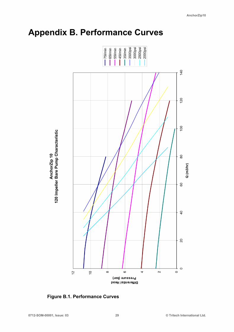
For the Volvo F11-10 motor the required flow may be chosen in conjunctionwith the performance curves supplied (Appendix B, Performance Curves).The maximum dead head water pressure is a function of the impeller speedwhich is directly related to the hydraulic flow.
If limiting dead head pressure is important to protect the structural integrityof the anchor then this may be achieved by limiting the hydraulic flow orby settling the suction relief valve (or by a combination of both). Limitinghydraulic flow will also reduce the maximum available water flow. This willbe particularly significant if the flow limit is imposed by a restricting valverather than a direct flow control valve since the hydraulic pressure will alsobe severely restricted.
Usually anchors pull in quite progressively so the differential pressure buildsslowly and control can be achieved by manually stopping the pump whenthe anchor has reached the correct position or the pressure limit has beenreached.
Hydraulic Motor Shaft Seals
The pumps are fitted with either an 'H' (red) or 'V' (brown) type seal. The typeV is the standard seal and is high pressure, high temperature.
Replacement of seals with anything other than a genuine seal (or TritechInternational Ltd supplied seal) will invalidate the warranty.

AnchorZip10
0712-SOM-00001, Issue: 03 14 © Tritech International Ltd.
4. Operation
4.1. Seating the Anchor
!Caution
Damage will occur to the impeller and pumping cavity if it is usedto pump sharp silt or sand over an extended period.
This may occur if:
1. The seabed into which the anchor is inserted has erupted inside the anchorallowing significant quantities of material to be drawn down the sides andthen throught he interior of the anchor. This will mean that the anchor hasbeen excavated into position rather than properly drawn in.
2. The anchor is drawn too far into the seabed and pumping is maintained.
Correct Incorrect 1 Incorrect 2
Figure 4.1. Correctly Seating the Anchor
Allowing this to happen is not only detrimental to the pump, but more seriouslyin the first instince is highly detrimental to the security of the installed anchor.In both cases installation will take much longer than normal.

Operation AnchorZip10
0712-SOM-00001, Issue: 03 15 © Tritech International Ltd.
4.2. Suction Pressures in Shallow Water
The impeller based AnchorZip10 pump relies on a head of water above the pump inorder to acheive differential suction pressures otherwise cavitation damage will occur.
In Suction mode
In Blowing mode
Water flow directionthrough pump
Water flow directionthrough pump
Enclosed tank(Anchor)
Water inletfrom sea
Enclosed tank(Anchor)
Water out to sea
Impellor
100mP =11 barA
P =6 barA
P =11 barA
P =16 barA
ΔP=5 bar
ΔP=5 bar
ΔP=5 bar
ΔP=5 bar
100m
ΔP is differential pressure between ambient sea pressure and the enclosed tank.
PA is the absolute pressure.
Figure 4.2. Performance in Shallow Water

Operation AnchorZip10
0712-SOM-00001, Issue: 03 16 © Tritech International Ltd.
P =0 barA
P =6 barA
ΔP=5 bar
ΔP=5 bar
ΔP=5 bar
P =1 barA
Nearsurface
SUR
FAC
E
P =0 barA
P =9 barA
ΔP=5 bar
ΔP=5 bar
ΔP=5 bar
P =4 barA
30M
30M
P =6 barA
P =16 barA
ΔP=5 bar
ΔP=5 bar
ΔP=5 bar
P =11 barA
100M
100M
Air
Water
Cavitates P<1 bar
Cavitates P<4 bar
OK P=5 bar
Figure 4.3. Depth versus suction capability

Operation AnchorZip10
0712-SOM-00001, Issue: 03 17 © Tritech International Ltd.
4.3. Testing in Air
!Warning
Under no circumstances must the flow be allowed to exceed 70litres per minute when testing in air.
There is no back pressure on the impeller to control its speed and manyvehicle hydraulic systems are capable of higher deliveries when there are nothrusters running. Motor over-speed can cause a catastrophic failure
To avoid excessive wear and the possibility of damaging the impeller andbody, the unit should not be run for extended periods out of the water (nomore than about 30 seconds). This is especially true when the unit is new.Absence of water around the plastic removes the natural cooling mechanismand may result in the moving parts becoming misshapen due to the heat.

AnchorZip10
0712-SOM-00001, Issue: 03 18 © Tritech International Ltd.
5. Maintenance
!Warning
Do not power the pump or hydraulic valve actuators until all hosesare properly connected to the pump.
There is a serious risk of injury to fingers if inserted into either thepower water intake or the pump delivery port.
If undertaking any testing operations suitable guards and othersafety measures must be in place.
5.1. Pre-diveBefore use check the following:
• All hoses are secure
• All mountings are secure
• Clean water suction strainer is in place and clear
Note
If the vehicle is inactive for more than 48 hours run fresh water intothe clean water suction strainer for a few minutes and then spin thehydraulic motor for about 15 seconds (taking care not to allow it toover-speed).
5.2. StorageIf the pump is removed from the vehicle, then the hydraulic ports should beblanked off with metal caps and the unit washed out with fresh water.
Leave the actuator valves in their retracted position.
Visually inspect the leading edges of the power pump impeller for damageand erosion.
Up to four blades may have leading edge damage of 5mm width and 4mmdepth before replacement becomes essential.
If the majority of leading edges are eroded more than 3.5mm back from thebore of the inlet nozzle then consideration should be given to replacing theimpeller.

Maintenance AnchorZip10
0712-SOM-00001, Issue: 03 19 © Tritech International Ltd.
5.3. Dismantling and Reassembly
!Warning
Before carrying out any maintenance work on the pump unit it isessential to ensure that the vehicle hydraulic system has been de-pressurised including compensation pressure.
7
2
6
10
12
11
3
1
4
13
9
7
2
5
8
Figure 5.1. AnchorZip10 Parts Diagram

Maintenance AnchorZip10
0712-SOM-00001, Issue: 03 20 © Tritech International Ltd.
Table 5.1. Parts List
Item QTY Part Number Old Part Number Description1 1 S10523 TI-F11-10-99098P Speedi Sleeved F11-10 Motor
2 2 S10500 TI-AZ10-002B Slide Bar
3 1 S10502 TI-AZ10-003B Main Case
4 1 S10503 TI-AZ10-004A Case Top
5 1 S10501 TI-AZ10-003-03B Interface Block
6 1 S10505 TI-AZ10-006-LP Valve Ring - Low Pressure
6 1 S10504 TI-AZ10-006-HP Valve Ring - High Pressure
7 4 S10506 TI-AZ10-007A Spacer
8 1 S10507 TI-AZ10-008A Valve Bar
9 2 S10555 TI-10/110-0-RSE-C 110mm Stroke Actuator
10 12 S10518 TI-C04800742250S Spring, Compression, 12.19mm OD x57.15mm lg
11 1 S10509 TI-BS622NI70 'O' Ring, NI70, BS622
12 1 S10548 TI-ZJU-8907 Zip 120mm Impeller
1 S10549 TI-ZJU-8908 ZP Impeller Mount Boss
1 S10550 TI-ZJU-8909 ZP Impeller Retainer
13 1 S11053 TI-3002-01-000 Volvo Motor Protector Assembly
Table 5.2. Hardware List
QTY Part Number Old Part Number Description12 S10467 TI-89510-M12-120 Fastener, C/Sink Allen Head, M12 x 120, SS
A4 80
4 S10470 TI-89510-M12-90 Fastener, C/Sink Allen Head, M12 x 90, SSA4 70
2 S10469 TI-89510-M12-50 Fastener, C/Sink Allen Head, M12 x 50, SSA4 70
4 S10473 TI-89510-M6-18 Fastener, C/Sink Allen Head, M6 x 18, SS A480
18 S10487 TI-89620-M12 Nyloc Hex Nut, M12, SS A4
18 S10490 TI-89710-M12 Flat Washer, M12, SS A4
1 S10491 TI-89710-M6 Flat Washer, M6, SS A4
2 S10485 TI-89550-M8-50 Fastener, Hex Head, M8 x 50, SS A4 80
2 S10484 TI-89550-M8-40 Fastener, Hex Head, M8 x 40, SS A4 80
2 S10488 TI-89620-M8 Nyloc Hex Nut, M8, SS A4
1 S10480 TI-89530-M6-20 Fastener, Socket Head, M6 x 20, SS A4 80
Reverse Valve Actuators
The reverse valve actuators are retained by set screws through the sphericaljoints at each end of the cylinder. Seal kits are available for the cylindersshould replacement become necessary.

Maintenance AnchorZip10
0712-SOM-00001, Issue: 03 21 © Tritech International Ltd.
Relief Valve Slipper Ring and Setting Relief Pressure
Early models of the AnchorZip10 had a standard interface block allowingsuction relief over a pressure range of 0.95 to 4.1 bar configurable by selectingdifferent quantities of weak and strong springs. For pressures above 4.1 bara modified interface block was required which clamped the relief valve shutand allowed higher pressures to be achieved without relief.
The later versions of the AnchorZip10 removed the need for the modifiedinterface block by introducing a new high pressure valve ring. If this new valvering is used in conjunction with the existing low pressure valve ring a rangeof pressure relief from 0.81 and 9.27 bar is achievable. This can be doneby simply varying the quantities of the same spring strength. The revisedinterface block supplied has an o-ring groove so that the higher pressuresare easier to achieve.
Note
This manual only details adjustment of the later versions of theAnchorZip10. If in doubt as to which version is to hand, pleasecontact Tritech International Ltd Technical Support.
Setting Relief Pressure
The relief interface block (item 5 on Figure 5.1, “AnchorZip10 Parts Diagram”)containing the valve ring is held in place by the slide bars mounted to the pumpbody and the hydraulic actuators. It may be removed by undoing the boltssecuring the actuator spherical joints to the valve bar (item 8 on Figure 5.1,“AnchorZip10 Parts Diagram”), leaving the interface block free to slide alongthe slide bars to the edge of the pump body. Due to the spring tension it willbe quite stiff to move and can be edged along by tapping the interface blockwith a soft faced hammer.
!Warning
The assembly is spring loaded. Great care must be exercised notto remove this item without first clamping the ring to the interfacebody.
Once the interface block has reached the edge of the main block it should bevery carefully knocked until the valve ring (item 6 on Figure 5.1, “AnchorZip10Parts Diagram”) is visible by about 12mm. A G clamp should then be fastenedaround the block and exposed parts of the valve ring.
The interface block can then be moved again very carefully until 60% of thevalve ring is exposed. Two further G clamps should then be applied acrossthe diameter of the valve ring. The unit can then be fully removed and the Gclamps carefully released to de-energise the springs.

Maintenance AnchorZip10
0712-SOM-00001, Issue: 03 22 © Tritech International Ltd.
Figure 5.2. LP Valve Ring Figure 5.3. HP Valve RingSprings bar psi
3 0.81 124 1.08 166 1.62 238 2.16 319 2.43 3510 2.7 3912 3.24 47
Springs bar psi3 2.32 344 3.09 456 4.64 678 6.18 909 6.95 10110 7.73 11212 9.27 134
Note
Springs must always be fitted in a symmetrical pattern.
Use spring: S10518
The Interface Block
Lightly grease the S10509 (TI-BS622NI70) o-ring and place it in the valvering o-ring groove.

Maintenance AnchorZip10
0712-SOM-00001, Issue: 03 23 © Tritech International Ltd.
Figure 5.4. Valve Ring
On the interface block place the correct quantity of S10518 springssymmetrically in the holes provided.
Figure 5.5. Springs in Place
Place the valve ring over the springs and tighten using G clamps

Maintenance AnchorZip10
0712-SOM-00001, Issue: 03 24 © Tritech International Ltd.
Figure 5.6. Valve Ring in Place
Compress the valve ring until flush with the block face and mount the interfaceblock on the AnchorZip10. Carefully remove the G clamps and the block slidesinto position. To move the block to its final position, tap the block with a softfaced hammer. Once the block is in position attach the actuators.

Maintenance AnchorZip10
0712-SOM-00001, Issue: 03 25 © Tritech International Ltd.
Figure 5.7. Actuators Re-attached
Finally apply an anti-seize compound to the M16 threaded inserts to aidlubrication when fitting the mating connection and grease/fit the BS156(S10508) o-ring to the interface block if required.
Hydraulic Motor and Impeller
In order to remove the motor and impeller it is necessary to completelydisassemble the pump.
First remove the actuator cylinders and interface block, remove all the boltsholding the guide bars and case parts together and then split the case. Theimpeller can then be removed from the pump shaft by undoing the set screwat the centre of the impeller boss, undoing the bolts securing the Volvo motor,and easing the motor away from the top case which will in turn pull off theimpeller.
When reassembling apply some anti-seize grease to the motor shaft beforefitting the impeller. Press the impeller boss onto the shaft right up to theshoulder. Assemble the retainer onto the shaft end and secure the setscrewusing a small quantity of Loctite. If the impeller has been removed fromits mounting boss, replace the impeller on the boss and secure the fourcountersunk screws with Loctite.

AnchorZip10
0712-SOM-00001, Issue: 03 26 © Tritech International Ltd.
6. TroubleshootingIf the pump is experiencing poor performance check the following:
• Check that there is no sign of any suction hose in use collapsing undersuction.
• Check the operation of the reversing system for full stroke.
• Check that the hydraulic motor runs freely without excessive noise orvibration.
• Check that the hydraulic flow meets the specification.

App
endi
x A
. Mot
or P
rote
ctor
Ass
embl
y Pr
oced
ure

Ass
embl
y In
stru
ctio
nR
emov
e an
y ex
istin
g po
rt fit
tings
from
the
F11-
10 V
olvo
mot
or. E
nsur
e th
at th
e to
p fa
ce o
f the
mot
or is
free
from
any
deb
ris s
uch
as p
aint
, dirt
or g
rit. C
lean
and
deg
reas
e th
e su
rface
.
1.P
lace
the
10 m
m H
igh
Car
bon
chro
me
Allo
y B
all B
earin
g [4
] int
o th
e V
alve
Blo
ck F
11-1
0 [3
] and
sea
t in
plac
e.
2.A
pply
a s
mal
l am
ount
of a
nti-g
allin
g co
mpo
und
to th
e th
read
and
a s
mal
l am
ount
of M
olyk
ote
111
silic
on g
reas
e to
the
O-r
ings
on
the
Plu
g H
ex H
ead
[6]
3.P
lace
the
Com
pres
sion
Spr
ing
[5] i
nto
the
Val
ve B
lock
F11
-10
8 an
d se
cure
in p
lace
by
tight
enin
g do
wn
the
Plu
g H
ex H
ead
[6].
4.P
lace
a S
EA
L D
owty
3/4
" Sel
f Cen
tre S
/S R
ing
[7] o
n ea
ch 3
/4- 1
4 B
SP
- JI
C 1
2 C
onne
ctor
[1].
5.P
lace
a S
EA
L D
owty
3/8
" Sel
f Cen
tre S
/S R
ing
[8] o
n th
e 3/
8-19
BS
P J
IC 6
Con
nect
or [2
].
6.P
lace
the
asse
mbl
ed c
ompo
nent
s fro
m in
stru
ctio
n 4
& 5
into
the
top
of V
alve
Blo
ck F
11-1
0 [3
].
7.G
reas
e w
ith M
olyk
ote
111
and
plac
e an
O-r
ing
32 x
2 [1
0] in
to e
ach
groo
ve o
n th
e V
alve
Blo
ck F
11-1
0 [3
] Bas
e.
8.G
reas
e w
ith M
olyk
ote
111
and
plac
e an
O-r
ing
20 x
2 [9
] int
o th
e gr
oove
on
the
Val
ve B
lock
F11
-10
[3] B
ase.
9.A
pply
a s
mal
l am
ount
of a
nti-g
allin
g co
mpo
und
to th
e th
read
s of
the
BS
P C
onne
ctor
s [1
] & [2
]
10.M
ount
the
asse
mbl
ed c
ompo
nent
s fro
m in
stru
ctio
n 8
onto
the
F11-
10 V
olvo
Mot
or [1
3] a
nd ti
ghte
n do
wn
usin
g an
adj
usta
ble
span
ner.
11.P
lace
the
Cap
, Fem
ale
No
12 J
IC C
arbo
n S
teel
[11]
& C
ap, F
emal
e N
o 6
JIC
Car
bon
Ste
el [1
2] o
nto
the
BS
P C
onne
ctor
s [1
] & [2
] and
han
d tig
hten
Item
New
Par
t Num
ber
Old
Par
t Num
ber
Des
crip
tion
QTY
1S
1044
6TI
-300
2-01
-002
Mot
or P
rote
ctor
Con
nect
or, 3
/4-1
4 B
SP
2
2S
1044
7TI
-300
2-02
-003
Mot
or P
rote
ctor
Con
nect
or, 3
/8-1
9 B
SP
1
3S
1044
5TI
-300
2-01
-001
Mot
or P
rote
ctor
Val
ve B
lock
, F11
-10
1
4S
1049
7TI
-901
00-1
0B
all B
earin
g, 1
0mm
Hig
h C
arbo
n C
hrom
e1
5S
1052
2TI
-D21
770
Spr
ing,
Com
pres
sion
1
6S
1046
1TI
-894
01P
lug,
Hex
Hea
d, 6
P50
NS
S, 3
16 S
/S1
7S
1045
9TI
-893
01S
eal,
Dow
ty, 3
/4, S
elf-C
entre
, S/S
Rin
g2
8S
1045
8TI
-893
00S
eal,
Dow
ty, 3
/8, S
elf-C
entre
, S/S
Rin
g1
9S
1051
1TI
-BS
I020
0-20
NI7
0O
-Rin
g 20
x 2
1
10S
1051
3TI
-BS
I032
0-20
NI7
0O
-Rin
g 32
x 2
2
11S
1045
7TI
-892
02C
ap, F
emal
e JI
C12
Car
bon
Ste
el2
12S
1045
6TI
-892
01C
ap, F
emal
e JI
C6
Car
bon
Ste
el1
13S
1052
3TI
-F11
-F10
-990
98P
Pai
nted
F11
-10
Mot
or1
AnchorZip10
0712-SOM-00001, Issue: 03 29 © Tritech International Ltd.
Appendix B. Performance Curves
Figure B.1. Performance Curves


