+ All Categories
Home > Documents > and Design Improvement, Phase I: Feed'Pump Hydraulic ...

and Design Improvement, Phase I: Feed'Pump Hydraulic ...

Date post: 23-Mar-2022
Category:
Upload: others
View: 1 times
Download: 0 times
Share this document with a friend
155
Feed'Pump Hydraulic Performance and Design Improvement, Phase I: J2esearch Program Design Tolume 1 ^^ Keywords: Feed Pumps Feed Pump Reliability Feed Pump Hydraulics Feed Pump Design Feed Pump Research Feed Pump Specifications Prepared by Borg-Warner Corporation (Byron Jackson Pump Division nr^ Borg-Warner Research Cente. Carson, California and Massachusetts Institute i Cambridge, Massachusetta EPRI EPRI CS-2323 Volume 1 Project 1884-6 Final Report March 1982 ELECTRIC POWER RESEARCH INSTITUTE
Transcript

Feed'Pump Hydraulic Performance and Design Improvement, Phase I:

J2esearch Program Design Tolume 1 ^^

Keywords: Feed Pumps Feed Pump Reliability Feed Pump Hydraulics Feed Pump Design Feed Pump Research Feed Pump Specifications

Prepared by Borg-Warner Corporation (Byron Jackson Pump Division nr^ Borg-Warner Research Cente. Carson, California and Massachusetts Institute i Cambridge, Massachusetta

EPRI EPRI CS-2323 Volume 1 Project 1884-6 Final Report March 1982

E L E C T R I C P O W E R R E S E A R C H I N S T I T U T E

DISCLAIMER

This report was prepared as an account of work sponsored by an agency of the United States Government. Neither the United States Government nor any agency Thereof, nor any of their employees, makes any warranty, express or implied, or assumes any legal liability or responsibility for the accuracy, completeness, or usefulness of any information, apparatus, product, or process disclosed, or represents that its use would not infringe privately owned rights. Reference herein to any specific commercial product, process, or service by trade name, trademark, manufacturer, or otherwise does not necessarily constitute or imply its endorsement, recommendation, or favoring by the United States Government or any agency thereof. The views and opinions of authors expressed herein do not necessarily state or reflect those of the United States Government or any agency thereof.

DISCLAIMER Portions of this document may be illegible in electronic image products. Images are produced from the best available original document.

Feed-Pump Hydraulic Performance and Design Improvement, Phase I:

Research Program Design Volume 1

CS-2323, Volume 1 Research Project 1884-6

Final Report, March 1982

Prepared by

BORG-WARNER CORPORATION 17929 Adria Maru Lane

Carson, California 90746

Byron Jackson Pump Division Borg-Warner Corporation

B P R I - C S ~ 2 3 2 3 V o l . 1 Principal Investigators

W. H. Brown, Project Leader pgga 903116 S. Gopalakrishnan

R. Fehlau

Consultant A. J. Acosta

Borg-Warner Research Center Borg-Warner Corporation

Principal Investigator W. E. Thompson

MASSACHUSETTS INSTITUTE OF TECHNOLOGY 77 Massachusetts Avenue

Cambridge, Massachusetts 02139

Principal Investigator D. G. Wilson

Prepared for

Electric Power Research Institute „„,..„.« .P nunumn 3412 Hillview Avenue BISTRIMITiOi OF THIS OOCUiEil IS USLIKTEO

Palo Alto, California 94304

EPRI Project Manager I. A. Diaz-Tous

Fossil Plant Performance and Reliability Program Coal Combustion Systems Division

ORDERING INFORMATION

Requests for copies of this report should be directed to Research Reports Center (RRC), Box 50490, Palo Alto, CA 94303, (415) 965-4081. There is no charge for reports requested by EPRI member utilities and affiliates, contributing nonmembers, U.S. utility associations, U.S. government agencies (federal, state, and local), media, and foreign organizations with which EPRI has an information exchange agreement. On request, RRC will send a catalog of EPRI reports.

NOTICE This report was prepared by the organization(s) named below as an account of work sponsored by the Electric Power Research Institute, Ino (EPRI). Neither EPRI, members of EPRI, the organization(s) named below, nor any person acting on behalf of any of them, (a) makes any warranty, express or implied, with respect to the use of any information, apparatus, method, or process disclosed in this report or that such use may not infringe private­ly owned rights, or (b) assumes any liabilities with respect to the use of, or for damages resulting from the use of, any information, apparatus, method, or process disclosed in this report

Prepared by Borg-Warner Corporation (Byron Jackson Pump Division and Borg-Warner Research Center) Carson, California and Massachusetts Institute of Technology Cambridge, Massachusetts

ABSTRACT

As a result of prior EPRI-sponsored studies, it was concluded that a

research program should be designed and implemented to provide an

improved basis for the design, procurement, testing, and operation of

large feed pumps with increased reliability and stability over the

full range of operating conditions. This two-volume report contains

a research plan which is based on a review of the present state of

the art and which defines the necessary R&D program and estimates the

benefits and costs of the program. The recommended research program

consists of 30 interrelated tasks. It is designed to perform the

needed researchi to verify the resultsi to develop improved compo-

nentsi and to publish computer-aided design methods, pump specifica­

tion guidelines, and a troubleshooting manual. Most of the technol­

ogy proposed in the research plan is applicable to nuclear power

plants as well as to fossil-fired plants.

ill

EPRI PERSPECTIVE

PROJECT DESCRIPTION

RP1884-6 is part of an EPRI program to improve the reliability of

feedwater pumps for large power-generating units. Problems of feed-

water pumps are a leading cause of unscheduled outages, and they are

estimated to have cost more than $408 million for replacement power

alone during 1981. The EPRI-sponsored program will be a multiyear

effort to provide an improved basis for the design, procurement,

operation, and testing of large feedwater pumps with increased reli­

ability and stability over the full range of operation. Phase I of

this effort was completed by two independent teamsi the result of one

team is reported here. The Phase I work was the preparation of a

research program design for the remainder of the overall EPRI effort,

including both theoretical and experimental research. The work was

based on surveys of architect-engineers, utilities, independent

research laboratories, and pump manufacturers as well as on the

resources of the team that performed the work.

In preparation for RP1884-6, EPRI sponsored several projects, which

are reported in the following publicationss Survey of Feed Pump

Outages (EPRI Final Report FP-754), Centrifugal Pump Hydraulic

Instability (EPRI Final Report CS-1445), and Recommended Design

Guidelines for Feedwater Pumps in Large Power Generating Units (EPRI

Final Report CS-1512). The complementary reports on Phase I work are

being published as EPRI Final Reports CS-2322, Volumes 1 and 2.

This two-volume report was prepared to provide utilities, manufac­

turers, and other interested parties with the results from the

Phase I research program design and related activities. The program

plan is expected to have a major influence on shaping EPRI work on

feedwater pumps, and the program plan will provide an overview of the

work that is required to improve the reliability and stability of

large feedwater pumps. In addition, the Phase I effort offers a

v

review of feedwater pump problems, design methods, theory, and

research requirements.

PROJECT OBJECTIVES

The general objective of this project was to prepare a research plan

for a multiyear effort to improve feedwater pump reliability and

stability. The plan was to include resource and facility require­

ments together with schedules and work descriptions.

Specific objectives werei

® To review feedwater pump design methods

® To survey problems in boiler feed pumps

m To assess feedwater pump experimental research

• To review pump theory

@ To formulate a statement of pump research requirement

• To detail plans for the proposed research program

PROJECT RESULTS

A comprehensive research program was formulated to develop a new

generation of advanced design feedwater pumps that would be highly

reliable and stable throughout their operating range. The proposed

research effort would require a five-year period and would cost

approximately $5.2 million (1981 dollars).

A Phase II integrated experimental and analytic effort would be

undertaken in the following fieldss hydraulics, cavitation, rotor

dynamics, and pump systems (interactions with connecting components

and piping). Full-scale verification tests would be performed to

examine the combined results of the foregoing efforts. Application

studies of pump components and economic methods would be made.

In Phase III, design methods for large feedwater pumps would be

developed. Computer-aided design methods would be prepared for

hydraulic analysis, cavitation, stress analysis, and rotor dynamics.

Pump specification guidelines would be prepared on the basis of the

vi

entire program, including monitoring and troubleshooting, materials

selection, and code modification.

I. A. Diaz-Tous, Project Manager Coal Combustion Systems Division

vii

ACKNOWLEDGMENTS

The authors wish to acknowledge the efforts of the following persons

for their major contributions during the course of this programs

K. W. Templin, of Byron Jackson Pump Division, and the many

architect-engineers and utility engineers interviewed during the con­

ducted surveys.

ix

TABLE OF CONTENTS

Volume 1

Page

Section 1

Feed Pump Procurement and Design Methods

1,0 Byron Jackson/EPRI Survey of Architect/Engineers 1-1

2.0 Pro Forma Specification 1-9

3.0 Review of the Current State of the Art of Feed Pump 1-10 Performance Prediction

4.0 Review of Feed-Pump Research and Development and of 1-11 Manufacturers of Boiler-Feed Pumps

Section 2

Problems of Feed Pumps

1.0 Byron Jackson/EPRI Survey of Utilities 2-1

2.0 Major Outage-Producing Failure Causes Identified in 2-3 EPRI FP-754, "Survey of Feed Pump Outages"

3.0 Problems Identified in EPRI NP-1571, "Repetitive 2-3 Failure Causes for Feedwater Pumps"

Section 3

Assessment of Feed Pump Experimental Research

1.0 Rotordynamics Testing 3-1

2,0 Advanced Instrumentation in Hydraulics 3-6

3.0 Cavitation Damage Testing 3-9

4.0 Summary of Existing Pump Test Facilities, Research 3-14 Facilities, and Instrumentation

Section 4

Review of Pump Theory

1,0 Hydraulics 4-1

2,0 Vibration in Pumps 4-6

3.0 Cavitation 4-9

XI

Pag

4.0 Two-Phase Flow in Pumps 4-14

5.0 Impeller Forces 4-15

6.0 Flow Instability 4-22

Section 5

Feed Pump Research Requirements

1.0 Feed Pump Problems 5-1

2.0 Phase lis Research Program 5-3

3.0 Phase IIIi Development of Design Methods 5-9

Section 6

Phase lis Research Program

HYDRAULICS

1.0 Off-Design Flow Studies 6-1

2.0 Velocity Field Measurements in a Pump Stage 6-3

3,0 Impeller/Volute Hydraulic Analysis 6-4

4,0 Hydraulic Instability 6-6

5.0 Analytical Study of Cavitation Performance 6-8

6.0 Analytical Study of Cavitation Damage 6-10

7.0 Correlation Between Noise and Cavitation Damage 6-12

8.0 Correlation Between Type of Cavitation and Damage Rate 6-13

9.0 Direct Measurement of Cavitation Damage in Impellers 6-14

ROTOR DYNAMICS

10.0 Development of Advanced Rotor-Bearing Systems for 6-16 Feed Water Pumps

11.0 Investigation of Axial Balancing Devices 6-17

12.0 Seal Ring Coefficients 6-18

13,0 Wear Ring Pressure Losses 6-20

PUMP SYSTEMS

14.0 System Interactions 6-21

15.0 Suction Effects on Pump Performance 6-23

xii

Page

FULL-SCALE VERIFICATION

16.0 Full-Scale Tests 6-24

17.0 Shaft Seals 6-29

APPLICATION OF RESEARCH RESULTS

18.0 Pump Component Development 6-31

19.0 Economic Evaluation Methods 6-32

Phase Ills Development of Design Methods

COMPUTER-AIDED DESIGN METHODS

20.0 Hydraulic Analysis 6-33

21.0 Cavitation Analysis 6-34

22,0 Analysis of Annular Pressure-Reducing Devices 6-35

23.0 Stress Analysis of Impeller Vanes, Impeller Shrouds, 6-36 and Shaft

24.0 Stress Analysis of Volute Lips and Diffuser Vane Tips 6-38

25.0 Rotordynamic Analyses 6-39

PUMP SPECIFICATION GUIDELINES

26.0 Instrumentation for Monitoring and Troubleshooting 6-41 Operating Peed Pumps

27.0 Selection of Materials of Construction 6-42

28.0 Review and Updating of Test Codes for Feed Pumps 6-43

29.0 Review and Updating of Standards for Feed Pump 6-43 Applications

TROUBLESHOOTING AIDS

30.0 Troubleshooting Manual 6-45

Section 7

Determination of Benefits

1.0 Objective 7-1

2.0 Approach 7-1

3,0 Research Program Benefit/Cost Ratio 7-2

4.0 Tabulation of Importance Factors 7-3

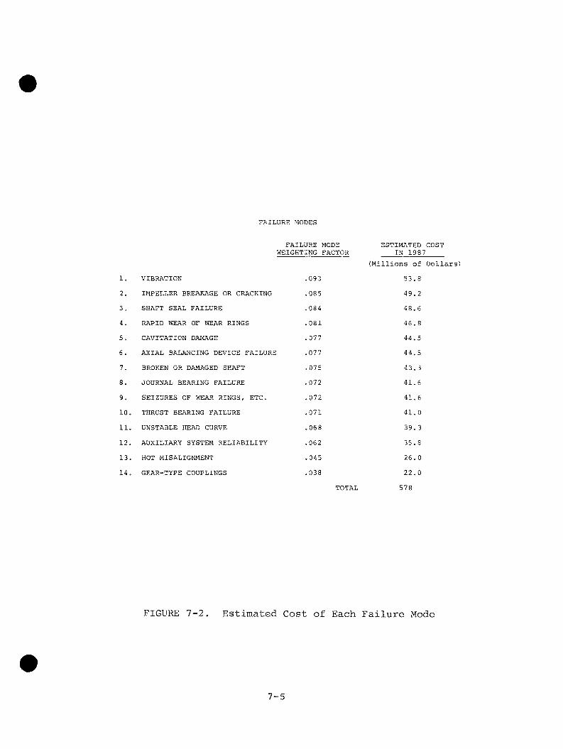
5.0 Estimation of Cost for Each Failure Mode 7-3

xiii

6.0 Weighted Benefit/Cost Ratio 7-6 7,0 Comments and Conclusions 7-6

Volume 2

Appendixes

Appendix

A Tabulated and Summarized Responses to Byron Jackson/EPRI A-1 Survey of Architect/Engineers

B Pro Forma Technical Specification, Turbine-Driven Boiler B-1 Feed Pumps for Large Fossil-Fired Power Plants

C Responses From Independent Research Laboratories and Pump C-1 Manufacturers Relating to Feed Pump Research and Develop­ment and to Current Pump Designs

D Tabulated and Summarized Responses to Byron Jackson/EPRI D-1 Survey of Utilities

E Rotor Dynamics Testing E-1

F Advanced Instrumentation in Hydraulics F-1

G Cavitation Damage Testing G-1

H Summary of Existing Byron Jackson Test Facilities and H-1

Instrumentation

I Computer-Aided Literature Search Methodology I-l

J Hydraulics J-1

K vibration in Pumps K-1

L Cavitation L-1

M Two-Phase Flow in Pumps M-l

N Impeller Forces N-1

0 Flow Instability 0-1

xiv

LIST OF FIGURES

Volume 1

Figure Page

3-1 Byron Jackson Test Rig 3-2

3-2 Air Test 3-4

3-3 Water Test 3-4

3-4 Critical Speed as a Function of Clearance for Smooth and 3-5 Grooved Wear Rings

3-5 Details of Crossover Region 3-8

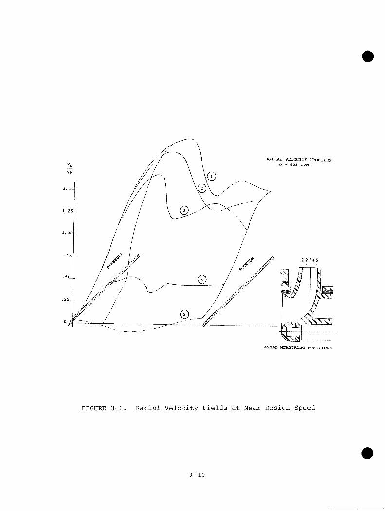
3-6 Radial Velocity Fields at Near Design Speed 3-10

3-7 Radial Velocity Fields at Low Flow 3-11

3-8 Three-Dimensional Frequency Response Plot 3-15

3-9 Three-Dimensional Pressure Pulsation Plot 3-16

4-1 Reverse Flow and Recirculation in a Pump Impeller 4-4

4-2 Cavitation Condition at Various Cavitation Levels 4-10

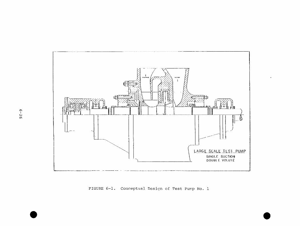
6-1 Conceptual Design of Test Pump No, 1 6-26

6-2 Conceptual Design of Test Pump No. 3 6-27

7-1 Tabulation of Importance Factors 7-4

7-2 Estimated Cost of Each Failure Mode 7-5

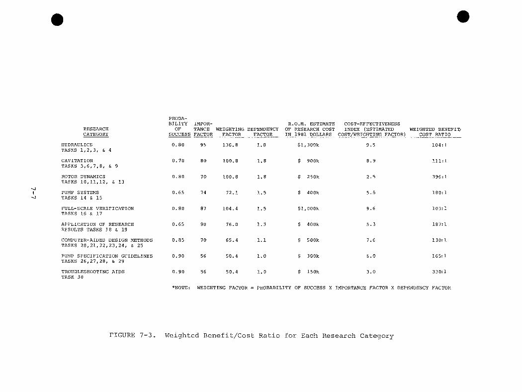
7-3 Weighted Benefit/Cost Ratio for Each Research Category 7-7

Volume 2

E-1 Byron Jackson Test Rig E-2

E-2 Air Test E-4

E-3 Water Test E-4

E-4 Critical Speed as a Function of Clearance for Smooth and E-5 Grooved Wear Rings

E-5 Test Rig Concepts E-6

E-6 University of Louisville Test Section Assembly E-8

XV

Figure Pag

E-7 Experimental Apparatus for Annular Seal Dynamic Properties E-8

F-1 Reference Beam Mode P-3

F-2 Differential Doppler Mode F-3

F-3 Schematic of Dual-Beam Laser-Doppler Anemometer F-4

F-4 Details of Crossover Region F-5

F-5 Schematic Representation of the Photodetector Signal F-7

F-6 Radial Velocity Fields at Near Design Plow F-8

F-7 Radial Velocity Fields at Low Flow F-9

G-1 Schematic of Beta Back-Scatter System G-2

G-2 Relationship Between Noise, Velocity, and Cavitation G-4 Erosion

G-3 Bubble Energy Spectra G-5

G-4 Cavitation Erosion Weight Loss and Spectrum Area G-6

H-1 Spectral Dynamics Model SD-2001D Digital Signal H-4 Processor

H-2 Vibration Amplitude vs. Frequency H-5

H-3 Order Tracking H-7

H-4 Example of Structural Resonance Excited by the Impeller H-8 Vane Frequency

H-5 Example of Discharge Pipe Acoustic Resonance Excited by H-9 the Impeller Vane Frequency

H-6 Campbell Diagram H-10

H-7 Campbell Diagram H-11

J-1 Reverse Flow and Recirculation in a Pump Impeller J-4

J-2 Static Pressure Distribution J-5

J-3 Comparison of Calculated Radial Forces With Test Data J-7

J-4 Flow Separation and Inlet Recirculation J-8

J-5 Reverse Impeller Discharge at 10% Flow Rate J-10

K-1 Rotor Vibratory Mode Shapes K-5

K-2 Pump Vibration Before and After Installation of K-7 Long-Taper Transition Pieces

xvi

Figure Page

L-1 Cavitation Conditions at Various Cavitation Levels L-2

L-2 Calculated Inception Point vs. Measured Inception for L-4 Standard Mixed-Flow Pump

L-3 Cavitation Damage Rate L-7

M-l Two-Phase Flow Head Loss Function M-3

xvii

EXECUTIVE SUMMARY

1.0 INTRODUCTION

Replacement energy costs alone, caused by feed pump problems, were

$408 million in 1981. Plant outages caused by feed pump problems

occur at significantly higher rates in large plants than in small

plants. Therefore, it was concluded that a research program be

designed and implemented to provide an improved basis for the

design, procurement, testing, and operation of large feed pumps with

increased reliability and stability over the full range of operating

conditions.

The purpose of the Phase I effort is to provide a Research Plan that

is based on a review of the present state of the art. The plan

defines the necessary research and development program and estimates

the benefits and costs of the program.

Most of the technology proposed in the Research Plan is applicable to

nuclear power plants as well as to fossil-fired plants,

2.0 BENEFIT/COST RATIO

The estimated benefit/cost ratio for the entire research and develop­

ment program is 154:1. It is more than 100:1 for each research

category. These ratios are based on an estimated cost of ^5.2

million 1981 dollars and the assumption that the program starts

early in 19 83 and continues through 19 87.

3.0 FEED PUMP PROBLEMS

Identified major outage-producing feed pump problems include vibra­

tion, impeller breakage and cracking, shaft seal failure, rapid wear

of wear rings, cavitation damage, axial balancing device failure,

broken or damaged shaft, journal bearing failure, thrust bearing

S-1

failure, seizure of wear rings and other close-clearance running

fits, unstable head-capacity curve, auxiliary system failure, hot

misalignment, and lack of flexibility in gear-type couplings.

Systematic and thorough analysis of each failure and determination

and reporting of the root cause are seldom possible because of the

manpower limitations imposed on the typical operating power plant

and the typical utility engineering staff. However, it is generally

agreed that many of the problems are related to operation of pumps

at very low flow or at very high flow.

4.0 CURRENT STATE OF THE ART

Current experimental research directed toward solving feed pump

problems and increasing reliability and stability is not being

conducted on a large scale, nor are the research efforts being

coordinated to achieve these goals,

4.1 Hydraulics

A theory that encompasses the combined effects of the interdependent

hydraulic components of a centrifugal pump on the real fluid stream

flowing through the pump is not yet available. The present inability

to model mathematically the interaction between the hydraulic

components (suction, impeller, and volute or diffuser) has thwarted

the prediction of performance. Further research in this general

area is needed, specifically to improve upon the theory that

describes the real fluid stream flowing through a pump. In

existing theoretical methods it is generally assumed that the flow

in one of the three hydraulic components of the pump can be analyzed

with sufficient accuracy, neglecting the influence of the other

two. It is also assumed that the flow is inviscid, irrotational,

steady, and two dimensional. As a result of these assumptions

it is possible to use potential flow theory. This method is

important because it foinns the basis for more advanced techniques.

However, when used alone it does not match experimental results very

well.

S-2

4.2 Vibration and Rotordynamics

An increasing demand for greater reliability of high-speed rotating

machinery and the introduction of specified vibration limits have

created renewed interest in the development of techniques to

anticipate vibration problems and methods to alleviate them. In the

rotordynamics area there are several types of analyses to be

considered; critical speeds, instability thresholds, and synchronous

and nonsynchronous forced response. Generally, the calculation

procedures for these analyses are well founded, but the methods for

determining the parameters necessary for the calculations are not.

However, there is an EPRI-sponsored program to determine the

stiffness and damping coefficients for various wear ring configura­

tions and to study the advantages of squeeze-film damper bearing

supports. This program has as its objective the development of

advanced rotor-bearing systems for feedwater pumps.

4.3 Cavitation

Cavitation can affect overall pump performance and reliability in

many ways. It can cause noise and vibration. Most importantly,

cavitation can produce large-scale erosion. Because of its

destructive effects, both designers and users have employed various

test techniques and basic research to determine the cavitation

characteristics of centrifugal pumps. Despite this effort, progress

in coping with the problems it creates has been slow. The problem of

cavitation combines complex material, chemical, and hydrodynamic

relationships. However, empirical predictions as to how and when the

onset of cavitation may occur are available. Predictions as to its

effects are more difficult. Although research has produced superb

scientific studies in bubble dynamics, incipient cavitation, cavity

mechanics, noise, material erosion resistance, and ways to alleviate

cavitation, there is still no complete and cohesive theory allowing

application of this knowledge to feed pump cavitation problems.

4.4 Impeller Forces

With the recent great increase in power-to-weight ratio of lall forms

of turbomachinery, it has become necessary to evaluate the

S-3

consequences of two additional fundamental conditions of the flow

of the working fluid. First, the forces arising from the pressure

distributions imposed upon both the rotor and the stator must be

predicted and/or measured; and second, the energy conversion process

must be assessed. It is now well established that the energy

conversion process is a function of time-varying or unsteady pressure

fluctuations. Thus, we may expect the resultant forces to be

unsteady as well. The forces imposed on a pump impeller, arising

both from flow within the impeller and from interaction with flow

outside the impeller in a volute or diffuser, are not well under­

stood. Therefore, the procedure is first to evaluate the time-

averaged conditions of radial and axial thrust. Ihen, in the area of

unsteady flow, the concept of rotating damping, forces due to

perturbations of the impeller channel flow, and the impeller/volute

or impeller/ diffuser interaction must be considered.

4. 5 Plow Instability

Flow instability in a pump system is created by the interaction of an

unstable pump head-capacity curve with a system that has unstable

characteristics. Power plant feedwater systems have the requisite

unstable characteristics, and a stable pump head-capacity curve

is necessary for successful operation of the system. Pump aesigners

use empirical methods to produce the needed pump characteristics,

but basic knowledge of this subject is incomplete.

4.6 Design Methods and Research by Manufacturers

Most pump manufacturers use design methods that are proprietary and

are based on a large empirical data base. Ihe bulk of their research

is internally funded, proprietary, and if published, not until long

after completion. Pump manufacturers tend not to perform basic

research; therefore, this work is generally conducted by research

laboratories and universities.

4.7 Peed Pump Specifications

Our survey of architect/engineers indicates that completion of the

research and development program will help them in areas such as

S-4

the following: better definition of short-duration transient and

upset low- and high-flow conditions, as opposed to long-duration

operation at minimum or maximum pump flow; better quantification of

required minimum flow, maximum flow, and NPSH; suction piping design

to avoid undesirable inlet flow profiles; discharge piping design to

eliminate discharge piping resonance and water hammer; specification

of proper testing, especially cavitation testing; specifications to

promote reliability; and proper specification of operating

instrumentation,

5.0 RESEARCH PLAN

The Research Plan consists of two parts: Phase II - Research

Program, and Phase III - Development of Design Methods. Phase II

consists of Tasks 1 through 19 and Phase III of Tasks 20 through

30. An outline of the Research Plan is shown in Figure S-1, A

surmmary of the Research Plan follows,

PHASE II: RESEARCH PROGRAM

HYDRAULICS

Task 1 - Off-Design Plow Studies

An extensive research program is necessary for a better understand­

ing of pump hydraulics at off-design flow and the problems created by

operation of feed pumps at off-design flow. An experimental study is

needed of flow patterns, impeller/volute (or diffuser) force

interactions, cavitation phenomena at impeller eye and discharge,

and unsteady pressures and loads in a representative boiler feed

pump impeller and volute (or diffuser) geometry. Included in this

research will be determination, by flow visualization, of the nature

and type of flow at off-design as a function of volute or diffuser-

impeller spacing, measurement of impeller/volute (or diffuser)

stiffness matrices at off-design flows, and a qualitative assessment

of the effects of impeller/volute (or diffuser) geometry on

cavitation onset. Transient local loads caused by volute/impeller

interaction will be studied by using surface-pressure measurement

with a sufficiently high frequency response. Further, special

S~5

RESEARCH PLAN

PHASE II - RESEARCH PROGRAM

HYDRAULICS Off-Design Flow Studies Velocity Field Measurements in a Pump Stage Impeller/Volute Hydraulic Analysis Hydraulic Instability

CAVITATION Analytical Study of Cavitation Performance Analytical Study of Cavitation Damage Correlation Between Noise and Cavitation Damage Correlation Between Type of Cavitation and Damage Rate Direct Measurement of Cavitation Damage in Impellers

ROTORDYNAMICS Development of Advanced Rotor-Bearing Systems for Peed Water Pumps Investigation of Axial Balancing Devices Seal Ring Coefficients Wear Ring Pressure Losses

PUMP SYSTEMS System Interactions Suction.Effects on Pump Performance

FULL-SCALE VERIFICATION Full-Scale Tests Shaft Seals

APPLICATION OP RESEARCH RESULTS Pump Component Development Economic Evaluation Methods

PHASE III - DEVELOPMENT OF DESIGN METHODS COMPUTER-AIDED DESIGN METHODS

Hydraulic Analysis Cavitation Analysis Analysis of Annular Pressure-Reducing Devices Stress Analysis of Impeller Vanes, Impeller Shrouds, and Shaft Stress Analysis of Volute Lips and Diffuser Vane Tips Rotordynamic Analysis

PUMP SPECIFICATION GUIDELINES Instrumentation for Monitoring and Trouble-Shooting Operating Feed Pumps Selection of Materials of Construction Review and Updating of Test Codes for Feed Pumps Review and Updating of Standards for Feed Pump Applications

TROUBLESHOOTING AIDS Troubleshooting Manual

FIGURE S-1. Outline of Research Plan

S-6

attention will be paid to these measurements at impeller and volute

vane tips.

Task 2 - Velocity-Field Measurements in a Pump Stage

It is also necessary to include in the research program quantitative,

three-dimensional measurements of flow patterns in a representative

boiler feed pump impeller and volute (or diffuser) geometry. Ihis

work is expected to provide a means of explaining the origin of

the unsteady impeller forces by observing the unsteady velocity and

pressure patterns. A laser-doppler velocimeter will be utilized for

this task.

Task 3 - Impeller/Volute Hydraulic Analysis

A finite element computer program for boiler feed pump hydraulic

analysis will be developed. This program will have three-dimensional

analysis capabilities, utilizing steady and unsteady algorithms, arid

will enable modeling of nonsymmetric volute or diffuser geometry.

Classical assiamptions regarding the blade exit condition will not be

used. A closure condition based on true viscous modeling will be

employed instead.

Task 4 - Hydraulic Instability

Also needed is an analytical and experimental study of the onset

of recirculation in the eye and at the discharge of a representative

boiler feed pump impeller. It is probable that large, unsteady

forces are related to recirculation in boiler feed pump impellers

and that these forces create hydraulic instability.

CAVITATION

Task 5 - Analytical Study of Cavitation Performance

The development of an analytical method for predicting the per­

formance of cavitating feed pumps is required. An advanced theory

for cavity flow in impellers will be developed based on a coordinate

transformation in which cavity zones can be explicitly recognized.

S-7

This theory must then be correlated to test data showing the effect

of advanced cavitation on the deterioration of head and efficiency in

a centrifugal pump stage. The analytical results depicting the extent

of cavitating volume at any operating condition will be an important

input to the development of damage rate prediction.

Task 6 - Analytical Study of Cavitation bamage

An analytical study of cavitation damage is required. A sound

theoretical basis for the determination of cavitation damage rate

will be established based on dimensional analysis of bubble dynamics,

collapse phenomena, and material properties. This will be correlated

with the experimental results from the work to be described as

Tasks 1, 8, and 9.

Task 7 - Correlation Between Noise and Cavitation Damage

An experimental correlation between noise and cavitation damage

rate will be made by using advanced acoustic instrumentation in

experimental facilities where cavitation damage rates can be

accurately controlled and measured. Any noise correlation that

emerges would be an extremely valuable tool for the diagnosis of an

operating feed pump and for the possible prevention of cavitation

damage.

Task 8 - Correlation Between Type of Cavitation and Damage Rate

Two or more distinct types of cavitation are known to exist. An

experimental correlation between type of cavitation and cavitation

damage rate is necessary for understanding the cavitation damage

problem. These correlations will be attempted by inducing impellers

to undergo different types of cavitation in an experimental piomp

loop.

Task 9 - Direct Measurement of Cavitation Damage in Impellers

An experimental program involving direct measurements of cavitation

damage in an impeller eye is necessary to correlate the results of

all of the other cavitation research. Methods under consideration

S-8

are soft-coating removal, local use of soft metallic material, and

use of pressure-sensitive film.

ROTORDYNAMICS

Task 10 - Development of Advanced Rotor-Bearing Systems for Feedwater

Pumps

Development of advanced rotor-bearing systems for feedwater pumps

is now being sponsored by EPRI projects RP-1266-7 and RP-18B4-4.

Dr. Maurice L. Adams, Jr., and Dr. Elemer Makay are the principal

investigators. This is an experimental study of wear ring force

coefficients aimed at determination of coefficients for existing

common wear ring geometries and at devising wear ring geometries with

better damping coefficients. We recommend an extension of this

work to include testing of geometries that represent long interstage

bushings, balancing drums, and throttle bushings. Another portion of

this work deals with the development of a squeeze-film damper support

for feed pump journal bearings.

Task 11 - Investigation of Axial Balancing Devices

Investigation of axial balancing devices is also a necessity. An

additional part of the research mentioned as Task 10 is the effort

directed at attenuation of axial vibration. An axial squeeze-film

damper thrust bearing support is suggested as a possible remedy to

the problems caused by the extreme rigidity of balancing disks.

Task 12 - Seal Ring Coefficents

To support the experimental work described as Task 10 and to promote

a better understanding of the problems involved and of the experi­

mental results, an analytical study of seal ring coefficients is

needed. Perturbation solution techniques will be employed to define

force components acting on the rotor due to small motion relative

to a centered position in the wear ring or seal. Documentation will

cover both the theoretical development of the seal force coefficients

and calculated results for a range of currently employed seal

geometries and operating conditions.

S-9

Task 13 - Wear Ring Pressure Losses

An experimental investigation of pressure-loss coefficients in wear

rings and other annular pressure-reducing devices is required in

relation to the above research work. It is also needed as an input

to one or more of the computer-aided design methods of Phase III.

Measurements will be made in an experimental facility where both

concentric and eccentric shaft/wear ring configurations can be

accommodated. Data will be accumulated for a broad range of Reynolds

nurabers>

PUMP SYSTEMS

Task 14 - System Interaction

A study of system interaction between the feed pump, the piping, and

the feedwater control system is required. To a lesser degree, this

study will also consider such structural components as baseplates,

foundations, etc. It will include such items as feed pump vibration

caused by piping resonance excited by pressure pulsations from the

pump, water hammer, determination of maximum allowable pressure

pulsations, sources of pump vibration caused by external excitations,

interrelationships between the pump and the feedwater control

system, and feed pump minimum flow bypass systems.

Task 15 - Suction Effects on Pump Performance

Also required is an investigation of the effects of suction

piping configuration and of suction transients on pump performance.

This will include analytical and experimental investigations of flow

profiles at feed pump inlets and their effect on performance. A

definition and quantification of the feed pump inlet transient

conditions created by a deaerator transient, a booster pxaap failure,

or by other upset conditions will be included. Experimental investi­

gation of pump first-stage performance during simulated upset suction

transients will also be undertaken.

S-10

FULL-SCALE VERIFICATION

Task 16 - Full-Scale Tests

Full-scale, full-speed tests of boiler feed pump stages will provide

verification of laboratory-scale research. All of the experimental

research indicated above (Tasks 1 through 15) will be conducted on

scale models. Even though the theory developed would transcend the

size effects, it is quite likely that certain obscure but significant

scale effects will remain undiscovered. This is particularly true

for cavitation-related work. Consequently, full-scale testing is

necessary to verify the theories, unearth the obscure mechanisms, and

thus close the loop between theoretical and experimental research.

Task 17 - Shaft Seals

Because shaft seal failures have been identified as the most fre­

quent cause of feed pump outages, a full-scale experimental inves­

tigation of shaft seals and shaft seal systems for feed water pumps

will be undertaken. A more efficient test program will result if

the shaft seal tests are separated from the boiler feed pump stage

tests described as Task 16.

APPLICATION OF RESEARCH RESULTS

Task 18 - Pump Component Development

Consolidation of the above research results will lead to and give

guidance to pump component development. For example, the results of

the research will lead to improved designs for wear rings and other

annular pressure-reducing devices and to improved impeller design and

improved understanding of the various design relationships between

impellers and volutes or diffusers. Full-scale development of such

devices as squeeze-film radial bearing supports and axial squeeze-

film damper thrust bearing support is also likely. Some pump

component development will involve large-scale testers, while other

developments will utilize the hardware from the full-scale verifica­

tion testing.

S-11

Task 19 - Economic Evaluation Methods

To complete the research phase of the program, a systematic

methodology for evaluating pump design elements and performance in

terms of total economics is required. The purpose is to provide

a basis for engineering and economic tradeoffs between investment

and operating costs related to feed pumps.

PHASE III: DEVELOPMENT OF DESIGN METHODS

COMPUTER-AIDED DESIGN METHODS

Task 20 - Hydraulic Analysis

The research results must be translated into design methods that can

be utilized by feed pump designers and others. A hydraulic analysis

based on the results of the research outlined as Tasks 1 through 4 i

required.

Task 21 - Cavitation Analysis

A cavitation analysis of annular pressure-reducing devices based on

the research outlined as Tasks 5 through 9 is required.

Task 22 - Analysis of Pressure-Reducing Devices

An analysis of annular pressure-reducing devices based on the

research outlined as Tasks 10 through 13 is needed.

Task 23 - Stress Analysis of Impeller Vanes, Impeller Shrouds, and

Shaft

A stress analysis of impeller vanes, impeller shrouds, and the pump

shaft, taking into account the fatigue stresses caused by unsteady

pressures and forces as well as the centrifugal forces on the vanes

and shrouds, is necessary.

S'-12

Task 24 - Stress Analysis of Volute Lips and Diffuser Vane Tips

It is also necessary to perform a stress analysis of the volute lips

or diffuser vane tips and the fatigue stresses imposed by unsteady

pressure loads.

Task 25 ~ Rotordynamic Analysis

A rotordynamic analysis that accounts for the stiffness, damping, and

virtual mass coefficients of the impellers and the wear rings and

other annular pressure-reducing devices is needed. The stiffness

and damping coefficients of radial bearings, which may be of an

advanced design, must also be known and integrated into the program.

PUMP SPECIFICATION GUIDELINES

Task 26 - Instrumentation for Monitoring and Troubleshooting

Operating Feed Pimips

Comprehensive pump specification guidelines will be published as

an aid to architect/engineers and users. These guidelines will

present the results of the research in a practical and usable

manner. A publication on instrumentation for monitoring and

troubleshooting operating feed pumps will be required.

Task 27 - Selection of Materials of Construction

Practices for the selection of materials of construction for large

feed pumps will be reviewed and updated.

Task 28 - Review and Updating of Test Codes for Feed Pumps

Test codes for feed pumps will also be reviewed and updated.

Task 29 - Review and Updating of Standards for Feed Pump Applications

A review and updating of standards for feed pump applications in view

of the completed research, incorporating its results, will be

provided.

S-13

TROUBLESHOOTING AIDS

Task 30 - Troubleshooting Manual

The research results should provide assistance in troubleshooting of

feed pumps. A troubleshooting manual will be prepared. The purpose

of this manual will be to aid in the identification, diagnosis,

definition, and resolution of problems experienced by existing

feed pumps. Included will be methods, analytical tools, and

experimental techniques that will be useful in the prevention of

problems or their solution when they occur.

6.0 CONCLUSIONS AND RECOMMENDATIONS

The great cost to the utility industry of feed pump problems and the

resulting plant outages can be reduced by implementation of the

knowledge obtained from a coordinated, large-scale research

program. The recommended research program consists of 3 0

interrelated tasks. It is designed to perform the needed research,

verify the results, develop improved components, and publish computer-

aided design methods, pump specification guidelines, and a trouble­

shooting manual.

The estimated benefit/cost ratio for the entire research and develop­

ment program is 154tl and is more than 100:1 for each research

category.

This program should be started as soon as possible to achieve

maximum savings to the utility industry.

7.0 REPORT ORGANIZATION

Volume 1 of this report consists of seven sections. The first four

sections outline and update feed pump procurement and design methods,

problems of feed pumps, assessment of experimental research, and

review of pump theory. These topics are covered in Volume 1 in suf­

ficient detail to support the last three sections which cover feed

pump research requirements, the Research Plan, and the determination

of benefits.

S-14

Volume 2 contains appendices covering the subject matter of the first

four sections of Volume 1 in much greater detail. Included are:

tabulated and summarized responses, in detail, to the surveys of

architect/engineers, utilities, independent research laboratories,

and pump manufacturers; a Pro Forma Technical Specification; and

considerable detail relating to current experimental research and

literature on such topics as hydraulics, vibration in pumps,

cavitation, two-phase flow, impeller forces, and flow instability.

References and bibliographies are included.

S-15

Section 1

FEED PUMP PROCUREMENT AND DESIGN METHODS

1.0 BYRON JACKSON/EPRI SURVEY OF ARCHITECT/ENGINEERS

Six architect/engineers (A/E's) were surveyed. Selection criteria

were:

1. The architect/engineering firm must be a leader in the design and construction of large fossil-fired and nu­clear power plants,

2. The engineers interviewed must personally be well quali­fied to answer questions relating to large feed pumps.

There are other A/E's who fulfill these criteria. Recent specifica­

tions from these other A/E's were examined, and a significant amount

of the information gained from these examinations was incorporated

into our Pro Forma Technical Specification (paragraph 2,0 of this

section and Appendix B), We were unable to conduct more interviews.

However, based on the examination of the specifications of the other

qualified A/E's, we believe that our decisions relating to the design

of a viable Research Program would not have been influenced to a

significant degree by additional interviews.

The detailed "Tabulated and Summarized Responses to Byron Jackson/

EPRI Survey of Architect/Engineers" is in Appendix A.

The first question relates to the expected sizes of fossil-fired

plants. A summary response was that most fossil-fired plants to be

built in the next ten years will range from 300 or 400 MWE to 800 or

1,000 MWE in size. TVA and AEP were mentioned as exceptions. They

have built and are expected to build more 1,300-MWE plants. Many

responders believe that the trend is toward smaller (400-MWE to 500-

MWE) plants. The probability of new supercritical plants is uncer­

tain.

1-1

The survey disclosed that the ultimate boiler feed pump, as defined

by flow and horsepower, has already been built. The 21,000-gpm,

11,000-feet TDH, 4,600-psi discharge pressure, 6 5,0 00-horsepower feed

pumps used by AEP in their 1,300-MWE plants are expected to be the

maximum size that will ever be required for fossil-fired plants.

Higher head and discharge pressure requirements, up to 5,500 psi, are

being considered but at lower flow and horsepower. Except for the

above, demand for pumps larger than 16,000 to 25,000 horsepower for

the next ten years, and ultimately for pumps larger than 2 5,0 00 to

45,000 horsepower, will be minimal.

Only one A/E distinguishes between the operating range (minimum flow

to maximum flow) for fossil plant boiler feed pumps during normal

operation and the operating range for short periods of time during

abnormal operation.

FOR BOILER FEED PUMPS, BETTER DEFINITION IS NEEDED OF SHORT-DURATION

TRANSIENT AND UPSET LOW- AND HIGH-FLOW CONDITIONS, AS OPPOSED TO

LONG-DURATION OPERATION AT MINIMUM OR MAXIMUM PUMP FLOW.

Most A/E's quote minimum flow as 25%.

One response seems to have great merit. It was pointed out that the

fuel system in the vast majority of existing and projected fossil-

fired plants becomes unstable below 20% load, and operation below 20%

load should really not be a significant consideration. The vast

majority of large plants normally operate at full load with two boiler

feed pumps in parallel. If one pump is shut down when plant load is

reduced, then the remaining pump will be at approximately 4 0% of its

design flow at 20% plant load. Except for the minor added cost of the

recirculating line piping and valves, there is no justification for a

minimum boiler feed pump flow of less than approximately 4 0% of design

flow with this common plant design.

SHOULD MINIMUM LONG-DURATION BOILER FEED PUMP FLOW BE DEFINED AS THE

FLOW REQUIRED AT MINIMUM PRACTICAL PLANT LOAD FOR FOSSIL-FIRED PLANTS?

Required maximum flow for feed pumps in fossil plants ranged from 115%

of design flow to 140% of design flow.

1-2

BETTER DEFINITION OF REQUIRED MAXIMUM BOILER FEED PUMP FLOW IS NEEDED.

For fossil-fired plants, all responders prefer to operate at design

load, with two 50% or 60% turbine-driven feed pumps. In addition, a

motor-driven start-up pump is installed and is used as a spare when a

turbine-driven pump is out of service. The size of the third pump

varies from 25% to 50% (20% when the turbine-driven pumps are 60%).

There is a difference of opinion relating to the justification of the

cost of a variable-speed electric drive for the third pump.

The obvious advantage of having the third pump and its spare parts

identical to the 50% turbine-driven pumps is often outweighed by

limitations on the size and cost of available electric drive systems.

For a given power plant, the electric drive system for a 5,500-rpm

variable-speed 50% pump is far more costly than that for a 3,580-rpm

constant-speed 25% pump. Also, the 50% pump may require a booster,

while the 25% pump could take suction from the deaerator.

Note that a 50% pump plus a 25% pump, both at 133% of pump design

flow and at a slightly increased speed, will give 100% feedwater flow

to the plant. This relates to the question of maximum flow for long

periods of time and why it should ever exceed 133%.

THE PROPER SELECTION OF THE SIZE OF THE START-UP/SPARE BOILER FEED

PUMP REQUIRES FURTHER STUDY.

All responders expressed doubt that any new nuclear power plant

commitments will be made within the next ten years for construction

in the United States. New nuclear plants are expected to appear in

foreign countries for many years.

Most responders expect that the range of sizes for new nuclear plants

to be built in the next ten years will be 900 to 1,300 MWE, In addi­

tion, 600-MWE plants will be built in developing countries.

The largest nuclear feed piomps anticipated within the next ten years

would operate at 23,000 gpm, 2,600 feet head, 1,400-psi discharge

pressure, and 18,000 horsepower. These figures combine booster pumps

1-3

and feed pumps.

The largest anticipated nuclear feed pump would operate at 40,000

gpm, 2,100 feet head, 1,600-psi discharge pressure, and 24,000 horse­

power. These figures are for the feed pump only.

Again, only one A/E distinguishes between the operating range (minimum

flow to maximum flow) for nuclear feed pumps during normal operation

and the operating range for short periods of time during abnormal

operation.

FOR NUCLEAR FEED PUMPS, BETTER DEFINITION IS NEEDED OF SHORT-DURATION

TRANSIENT AND UPSET AND LOW- AND HIGH-FLOW CONDITIONS, AS OPPOSED TO

EXTENDED OPERATION AT MINIMUM OR MAXIMUM PUMP FLOW.

One responder quoted minimum flow as 10% to 2 5% of design flow. The

other responses varied from 25% to 50%,

BETTER DEFINITION OF REQUIRED MINIMUM FLOW FOR NUCLEAR FEED PUMPS IS

NEEDED. IS IT DIFFERENT FOR PWR and BWR PLANTS?

Required maximum flow for feed pumps in nuclear plants ranged from

115% to 160%. The majority of responders require 130% or more.

A BETTER DEFINITION OF REQUIRED MAXIMUM FLOW FOR NUCLEAR FEED PUMPS IS

NEEDED. ARE THE REQUIREMENTS FOR PWR PLANTS DIFFERENT FROM THOSE FOR

BWR PLANTS?

For nuclear plants, all responders prefer two 50% turbine-driven feed

pumps for operation at design load. There is slightly more desire

for the third pump also to be 50% than was indicated for fossil

plants. However, one A/E indicated that 2 5% to 3 5% spare is consid­

ered adequate, one A/E does not install any spare feed pumps at all,

and one A/E does not install any spare feed pumps in PWR plants.

One A/E indicated, as an alternative, four 3 3% feed pumps. An en­

gineer involved with operation of a nuclear plant (not an A/E) said

1-4

that if a 50% feed ptimp shuts down, the resulting transient makes it

difficult to keep the plant operating. He would like to see more and

smaller pumps.

THE PROPER SELECTION OF THE SIZE OF THE SPARE NUCLEAR FEED PUMP RE­

QUIRES FURTHER STUDY.

There were wide variations in the responses relating to considerations

governing NPSH available to feed pumps.

It was agreed that NPSH is furnished to nuclear feed pumps by booster

condensate pumps in the majority of current plant designs. There is

no agreement, however, on the question of whether 50% capacity boiler

feed pumps in large fossil-fired plants should take suction from an

elevated deaerator or should be provided with booster pumps.

There is generally a preference that the 20% to 33% capacity motor-

driven boiler feed pumps should take suction from the deaerator and

should not have booster p\imps.

Half of the responders mentioned NPSH margin. Some spoke of desired

margins and some of required margins. Some were concerned with margin

at design flow, some with margin at runout flow, some with both.

Desired and required margins varied from 80% to 100% at design flow

and from 25% to 50% at runout flow. Desired or required margins in

some cases were tied to a specific NPSH test method, such as 0% head

drop on cold water.

THE SUBJECT OF NPSH MARGIN REQUIRES FURTHER CLARIFICATION.

Feed pump foundation design and piping design as related to suction

and discharge nozzle piping loads do not seem to be problems for any

of the responders.

Most responders try to provide at least five pipe diameters of

straight pipe into the pump suction. Several have unpublished inter­

nal specifications governing such things as allowable velocities,

specification of long-radius elbows, and avoidance of elbows at a

right angle to the plane of rotation of the first-stage impeller

1-5

unless additional straight-run pipe is provided.

ADDITIONAL AND MORE SPECIFIC INFORMATION ON THE DESIGN OF SUCTION

PIPING TO PROVIDE UNIFORM VELOCITY DISTRIBUTION TO THE PUMP SUCTION

WOULD BE WELCOMED BY MANY RESPONDERS.

Most responders believe that discharge piping resonance at vane-pass­

ing frequency is not a common problem and, generally, no analysis of

it is performed during plant design. Most responders feel that the

practical and economical approach is to attend to the few problems as

they occur.

The responders do not consider water hammer in feedwater systems to

be a pump-related problem,

ALTHOUGH DISCHARGE PIPING RESONANCE AND WATER HAMMER ARE NOT COMMON

PROBLEMS, WE BELIEVE THAT FURTHER STUDY OF THESE TOPICS SHOULD BE

CONDUCTED.

Seismic requirements imposed on feed pumps, if any, are minor.

No responders are presently requiring dry run of boiler feed pumps.

One requires a severe low NPSH test, and others are considering simi­

lar requirements.

Only one responder requires a dry run of nuclear feed pumps. Some

are considering severe low NPSH testing,

SEVERE LOW NPSH TESTING TO SIMULATE PUMP SUCTION UPSETS AND TRANSIENTS

SHOULD BE STUDIED.

Attemperation flows from 5% to 2 0% of design flow were anticipated by

various responders. This is a very wide range of opinions.

Several people mentioned that some coals to be used in the future may

cause worse slag formation and fouling. This may increase attempera­

tion requirements.

No re-entry designs are anticipated at this time by the responders.

1-6

Almost all responders indicated to some degree that they do not like

the concept of giving great weight to quoted pump efficiencies when

evaluating pump proposals, except to assess a penalty if the quoted

pump is a poor "fit." One will not give credit for any quoted

efficiency above 85%. Several others would like to do something

similar,

METHODS FOR THE EVALUATION OF QUOTED PUMP EFFICIENCIES SHOULD BE

INVESTIGATED.

Three responders evaluate minimum flow and three do not. One evalu­

ates piping cost only, one evaluates power cost only, and one evalu­

ates both,

THE SUBJECT OF MINIMUM FLOW HAS ALREADY BEEN IDENTIFIED AS ONE FOR

FURTHER INVESTIGATION.

Anticipated feed pump reliability is evaluated, one way or another,

by all responders. There is an increasing desire to do a more formal

analysis and, possibly, to credit or penalize pump proposals heavily

based on the results of such formal analysis. However, the present

data base is inadequate for this purpose.

THE FORMAL ANALYSIS OF FEED PUMP RELIABILITY SHOULD HAVE FURTHER

INVESTIGATION.

None of the responders makes a formal analysis of each manufacturer's

past service record. However, this item is almost always taken into

account, one way or another.

Only one responder evaluates shut-off head. Three responders specify

shut-off head not to exceed 130% of design head.

Maximum head per stage, maximum number of stages, or maximum suction

specific speed are seldom specified. All responders were reluctant

to become involved in pump design.

Maximum rpm is almost always specified, often because of speed limita­

tions imposed by available steam-turbine drives.

1-7

Most responders specify instrumentation to monitor both vibration and

radial shaft motion (orbit). Instrumentation to monitor axial shaft

motion (end float) is specified by three responders for nuclear feed

pumps and by two for boiler feed pumps. Only one monitors suction

and discharge pressure pulsations, and two specify instrumentation to

check hot alignment.

SPECIFICATION OF PROPER OPERATING INSTRUMENTATION SHOULD BE FURTHER

INVESTIGATED.

No responder is aware of proven instrumentation that will detect

rubbing of internal components in operating feed pumps.

No responder is aware of proven instrumentation that will detect the

onset of cavitation in an operating feed pump. Two responders men­

tioned instrumentation to measure available NPSH.

FURTHER INVESTIGATION OF INSTRUMENTATION FOR CAVITATION DETECTION

AND/OR MEASUREMENT OF AVAILABLE NPSH IS IN ORDER.

Four responders believe that analysis of fluid-borne noise can be a

valuable tool for monitoring an operating feed pump or for diagnosis

of feed pump problems. One responder believes that analysis of air­

borne noise can be valuable.

Specification of the throttle bushing type of shaft seals with injec­

tion and bleed-off is common. Most prefer temperature control of the

injection system. None will allow mechanical seals.

THE SUBJECT OF SHAFT SEALS AND RELATED INJECTION SYSTEMS STILL RE­

QUIRES FURTHER STUDY.

A stable head-capacity curve is specified, and the pumps are witness

tested by all responders.

There is a wide variation in specified shop tests and a general feel­

ing that existing test codes are inadequate, at least to some degree.

Three responders are not satisfied with vibration standards, two

1-8

would like to have pressure pulsation acceptance criteria, and one be­

lieves that NPSH tests are not accurate. There was, however, general

agreement that the best way to resolve any existing problems is by

revision of the Hydraulic Institute Test Code, not by having different

requirements for each A/E.

THE QUESTION OF WHAT CONSTITUTES A PROPER ACCEPTANCE TEST FOR A LARGE

FEED PUMP REMAINS OPEN.

The right to run field tests is always specified but seldom exercised.

Comments on previously published EPRI reports relating to feed pumps

were generally favorable.

2.0 PRO FORMA SPECIFICATION

Appendix B contains the "Pro Forma Technical Specification for

Turbine-Driven Boiler Feed Pumps for Large Fossil-Fired Power Plants."

Most feed pumps to be purchased during the next ten years will be in

this category. A modified specification would be required for the

start-up or spare motor-driven pump for a fossil-fired plant or the

feed pumps for a nuclear plant. This specification is intended to be

typical and illustrative.

This technical specification covers the requirements for the design,

manufacture, shop testing, packaging, storage and handling, shipping

and technical direction of installation and field testing of feed

pumps and accessories for large (600-MWE and larger) fossil-fired

power plants.

The pro forma specification is divided into three sections. The body

of the specification is intended to be general in nature and to apply

to all feed pumps of a given category. Table 1 contains the project

requirements that result from plant design considerations, particular

preferences of A/E's, and the requirements and preferences of the

utility. Addendum 1 is a definition of terms. Addendum 2 is a

Technical Bid Form to be filled out by the A/E and the pump

manufacturer.

1-9

3.0 REVIEW OF THE CURRENT STATE OF THE ART OF FEED-PUMP

PLRF0RI4ANCE PREDICTION

Only two requirements have to be met to predict the performance of a

turbomachine. One is to predict, at the combination of fluid veloc­

ity and blade velocity of interest, the outlet flow angle of each

streamline flowing through each row of blades. Using Newton's law in

the form of the Euler equation, the specific work or enthalpy rise of

the fluid along each streamline can then be found.

To predict the head or pressure rise from the specific work or enthal­

py rise, the second component of the prediction is required: the

losses. The pressure losses occurring at the fluid boundaries and in

the body of the fluid will be needed to predict the increase of pres­

sure, and the friction losses occurring because of windage, seal, and

bearing friction will be needed to predict the power input required

on the shaft.

The traditional design method has been to specify a combination of the

impeller vane discharge angle and the number of vanes, to assume a

stage efficiency (which means assuming the losses that will occur at

best-efficiency point), to refer to previous correlations or exper­

imental results to predict the impeller discharge flow angle

(alternatively the deviation or "slip factor"), and thereby to find

the impeller peripheral velocity that will give the desired head rise

per stage.

The actual impeller diameter and rotational speed at best efficiency

will depend on the driver. If the pump is to be turbine driven, the

shaft speed can usually be chosen to give an optimum specific speed

for a multistage arrangement, taking into account the need to avoid

shaft instabilities. If the pump is to be driven by an induction

motor running on a fixed frequency, then some compromise in specific

speed may be necessary.

Prediction of off-design performance is made from correlations of pre­

vious test results. Some correlations, for instance of slip factor,

are available in the literature. However, all manufacturers have

their own correlations, based on tests of impellers and pumps of their

1-10

own manufacture, and very accurate predictions can be achieved in

this way.

There is considerable effort in many places to predict pump perform­

ance from first principles, using computational fluid mechanics. A

principal purpose is to improve the shapes of the impeller blades and

of the hub and shroud, so as to be able to produce either a higher de­

sign-point efficiency or to ease manufacturing complexity or, prefer­

ably, both. It is also hoped that flow patterns at low-flow condi­

tions could be predicted, and measures could be taken that could in­

crease the efficiency, decrease the incremental pressure rise, and/or

make for smoother operation in these low-flow conditions.

The state of uncertainty of predictions given by analytical and even

empirical methods is illustrated by the fact that some manufacturers

still use models to back up their design work. The results of model

tests need correction factors before they can be used to predict full-

scale performance. However, the correlations of correction factors

are well known.

4.0 REVIEW OF THE FEED-PUMP RESEARCH AND DEVELOPMENT

This short review is based solely on the visits and discussions of

Professor David Wilson of M.I.T.

The only work specifically directed at boiler-feed pumps was being

undertaken in the laboratories of manufacturers of boiler-feed pumps.

The manufacturers to which this reviewer made visits or with whom he

had discussions were naturally unwilling to reveal all details of what

they were involved in, to avoid the transfer of valuable proprietary

information.

Very little work was apparently being carried out on hydraulic forces

and instabilities. In several independent centers the principal

activity was in computational fluid mechanics as applied to centri­

fugal pumps and compressors. Research and development into cavita­

tion was being carried out with models running at full-scale tip

speeds. The use of soft coatings, such as ink and aluminum, was

considered to be a successful approach for the evaluation of

1-11

cavitation.

Appendix C contains brief notes of the responses received from, first,

the independent research laboratories and, subsequently, from manu­

facturers.

1-12

Section 2

PROBLEMS OF FEED PUMPS

1.0 BYRON JACKSON/EPRI SURVEY OF UTILITIES

The detailed "Tabulated and Summarized Responses to Byron Jackson/EPRI

Survey of Utilities" is in Appendix D.

In reply to the questions regarding major problems in large boiler

feed pumps, failure modes mentioned included balancing device fail­

ures, cavitation damage, impeller vane and shroud failure (other than

by cavitation), seizures, shaft failures, lack of reliability of aux­

iliary systems (especially lube-oil systems and bleed-off piping sys­

tems) , gear-type coupling inflexibility, and hot misalignment.

Failure of balancing devices is frequently due to system upsets,

especially emergency trip conditions. Vibration, affecting seals and

bearings, is often due to hot misalignment after maintenance. Cavi­

tation damage is mostly due to prolonged service at off-design flow.

Seizures often are caused by bypass flow system problems and/or im­

proper start-up/warm-up procedures, mostly at start-up after mainte­

nance.

The corrective actions that have improved reliability include up­

grading of operator training, operating instructions, feedwater

system maintenance, and instrumentation.

It seems that, in general, failures at "mid-life" are rare. The

majority of failures are during "old age" and probably could have

been avoided by periodic maintenance, or they occur shortly after

inadequate or improper repairs.

With regard to failures in nuclear plants, responders mentioned

cavitation on one side of a double-suction impeller, malfunction of

the control system, internal wear, wrong shaft material, galling, re­

circulation line vibration, unreliable floating ring seals, inflexible

gear-type couplings, and recirculation system problems.

2-1

It is believed that all nuclear plants are in base load service.

All responded that instrumentation is used in the following areas to

monitor boiler-feed and nuclear-feed pump performance: discharge and

suction pressure, flow, water temperature, bearing vibration, and rpm.

There is no uniformity in scheduling of feed pump maintenance. One

responder said that maintenance was performed "every six years or

every four fuel cycles." Others replied that they depend upon hydrau­

lic and mechanical monitoring to alert them to the need for mainte­

nance. One said their base load plants are scheduled for two-week

outages every four to six months and that repairs are made at those

times. One makes an annual check of bearings, seals, and balancing

devices; another maintains the pump at the time of turbine inspection,

otherwise only in case of failure. The replies stated that mainte­

nance scheduling could be improved by better instrumentation and

better records.

The request for comments on EPRI publications CS-1512, NP-1571, and

FP-754 elicited positive responses for the most part.

A list of feed piomp problems identified by the Byron Jackson/EPRI

survey of utilities is as follows:

1. BALANCING DEVICE FAILURES

2. HOT MISALIGNMENT

3. FIRST-STAGE CAVITATION

4. SEIZURES

5. FAILURE OF INTERSTAGE PARTITIONS

6. CAVITATION DAMAGE

7. IMPELLER CRACKING OR BREAKAGE

8. INTERNAL LEAKAGE AND WASHOUT

9. GEAR-TYPE COUPLINGS

10. SHAFT FAILURES

11. VIBRATION

12. AUXILIARY SYSTEM RELIABILITY

The above list is not necessarily in order of severity or frequency

of the problems.

2-2

2.0 MAJOR OUTAGE-PRODUCING FAILURE CAUSES IDENTIFIED IN EPRI FP-754,

"SURVEY OF FEED PUMP OUTAGES"

The ten major outage-producing failure causes identified in EPRI

FP-7 54 are:

1. SHAFT SEAL FAILURE

2. VIBRATION: PUMP, PIPING, FOUNDATION

3. AXIAL BALANCING DEVICE FAILURE

4. JOURNAL BEARING FAILURE

5. CAVITATION DAMAGE

6. IMPELLER BREAKAGE OR CRACKING

7. RAPID WEAR OF WEAR RINGS

8. UNSTABLE HEAD CURVE

9. BROKEN OR DAMAGED SHAFT

10. THRUST BEARING FAILURE

The above items are listed in the order of total number of failures,

number 1 indicating the most frequent type of failure.

3.0 PROBLEMS IDENTIFIED IN EPRI NP-1571, "REPETITIVE FAILURE CAUSES

FOR FEEDWATER PUMPS"

A list of feed piomp problems identified in EPRI NP-1571 is as follows;

1. PROCUREMENT PRACTICES SUCH AS EMPHASIS ON HIGH QUOTED

EFFICIENCY, LOW COST, LOW REQUIRED NPSH AND LOW MINIMUM

FLOW

2. INCOMPLETE OR INCORRECT INFORMATION GIVEN TO THE VENDORS

3. COMPREHENSIVE TESTING NOT SPECIFIED OR NOT ENFORCED

4. INADEQUATE SPARE ROTATING ELEMENTS AND SPARE PARTS

5. FEEDWATER SYSTEM DESIGN

6. LACK OF SPARE PUMP ON STANDBY

7. FALSE AUTOMATIC FEED TRIPS IN NUCLEAR PLANTS

8. POOR OPERATING PROCEDURES

9. OPERATION ON TURBINE TURNING GEAR

10. FAILURE TO MONITOR AND EVALUATE PUMP OPERATING

PARAMETERS

2-3

11. LACK OF CONTROL OVER PUMP REPAIRS

12. LACK OF COMMUNICATION AMONG PEOPLE FROM UTILITIES,

ARCHITECT/ENGINEERS, VENDOR SERVICE, AND VENDOR DESIGN

ENGINEERS

13. GENERIC PROBLEMS OF PUMP DESIGN, SUCH AS INTERNAL HIGH-

PRESSURE SEAL WASHOUT, AXIAL BALANCING DEVICE FAILURES,

AND CAVITATION DAMAGE

14. INADEQUATE RESPONSE BY VENDOR SERVICE PEOPLE

15. INADEQUATE TECHNICAL SERVICE MANUALS

The above list is not necessarily in order of severity or frequency

of the problems.

2-4

Section 3

ASSESSMENT OF FEED PUMP EXPERIMENTAL RESEARCH

1.0 Rotordynamics Testing

It is becoming increasingly clear that one of the major factors af­

fecting the vibration response of centrifugal boiler feed pumps is

the stiffening effect of various close-clearance spaces within the

pump. Those include annular pressure-reducing devices, such as

wear rings, throttle bushings, center-stage pieces, balance drums,

etc. These devices play an important part by providing not only a

stiffening effect but also a damping effect. In many instances the

fluid in the clearance spaces also possesses a virtual inertia, also

known as virtual mass, and this too plays a part in determining the

vibration response of the system.

Experimental work so far can be broadly classified in two major cate­

gories. In the first the shaft is allowed to undergo whirling motion.

In the second it is made very stiff, and the forces at the wear rings,

etc., are directly measured. The advantage of the first type of test

is that one can immediately detect the presence of a critical speed,

which is a matter of great practical significance. The difficulty

associated with this type of test is that understanding why a

particular critical speed is observed is dependent upon the

mathematical modeling made for the entire system. Consequently, there

is no direct substantiation of the effect of the annular clearances.

In the second set of tests, which uses a stiff shaft, the forces are

directly measured and, therefore, the sealing ring properties are

immediately and directly established.

Recent tests done at Byron Jackson use the flexible-shaft approach.

As shown in Figure 3-1, a single-stage, double-suction, horizontal

pump was installed in a test rig, wear rings were provided on either

side, and the pump was run at variable speed. The pressure difference

across the wear rings was changed independently of the speed, and the

vibration of the snaft was measured by using two proximity probes.

3-1

PRESSURE GAUGE

PROXIMITY PROBE

FIGURE 3-1. Byron Jackson Test Rig

3-2

when the tests were first conducted in air, the critical speed was

clearly observed as shown in Figure 3-2, which plots the once-per-

revolution amplitude versus the speed. It also shows that the phase

shift of nearly 180° is observed as well. When water was introduced

into the pump, the amplitude response characteristics changed

dramatically. For example, Figure 3-3 shows that when smooth wear

rings were used with a nominal clearance of .016 inch (diametral

clearance) and there was a pressure difference across the rings of

250 psi, no discernable critical speed was evident; also there was

scarcely any phase shift. In this case, the critical speed appears to

be totally suppressed? the fact that it is can be easily be demon­

strated by calculations. However, when the wear ring clearance is

opened up or when the wear ring is deeply serrated, critical speed

phenomena begin to appear again. It is also interesting to note that

the effect of wear on the rings is to reduce the critical speed,

particularly for rings that are smooth; this can be seen in

Figure 3-4. It shows that as the diametral clearance of the seal

rings increases, the stiffening effect is reduced and, therefore, the

critical speed decreases. The effect, however, is much weaker for

grooved rings, because they produce less stiffness.

Using sucn experiments, one can determine the performance of the

sealing rings. however, since several assumptions are made with re­

gard to the modeling of the system, it is quite conceivable that the

indirect measurement of sealing ring properties, as above, could be

considerably in error. Therefore the testing using a stiff shaft is

more straightforward.

There are several methods by which a stiff-shaft test can be made to

determine the sealing ring properties. EPRI is sponsoring stiff-

shaft testing in which the journal is set with an offset and then

vibrated by orbiting it accurately. In this research it is

possible to vary the precession speed with respect to the rotating

speed. This testing is being done by M. L. Adams and E. Makay. All

twelve dynamic force coefficients, as described in Section 4, para­

graph 2.3, of this report, can be determined accurately in this setup.

Recent theoretical work has shown that it will be possible to

determine the sealing ring coefficients by means of theoretical

3-3

DIS

PL

AC

EM

EN

T

(yiL

S.

PK

-PK

) P

HA

SE

LA

G

(DE

GR

EE

S)

JT^H

i-i

y'l

q-tr

it

^

T3F

-:r

;i

-p'

111!

H

O

G

m

I 1-3

tD

05

rt

DIS

PL

AC

EM

EN

T

(MIL

S

PK

-PK

) P

HA

SE

LA

G

(DE

GR

EE

S)

33

13

O,

M^

®

•f~

~T

-

«n

@

fM

o

^

h=

rrti

r-~

trrt

±tr

tri±

rttt

^^

fc:r

-irzd

rrd=

rb±£

r iid

jrb

:: J

-..L

IL!j

-.id

'ft-:

4-—

f—i—

rTr-

-*rT

-hT

t^hT

n^^

—T

::3q=

=^^

l-

-4

--

t-

^-

L-

»U

--

--

--

--

'-

rT

^

-H

r

t-

T-

M-

-^

I f-

l —

^ 1

1 .

1 )

' 1

r~^

^

1 •

M H

!

t ,

1 1

i '

' 1

^t-

l ri

—,

M

1'

J 1

! •

-1

' '

' !

1!

' i

i 1

j !'

1

! 1

i M

;

iHr

r

li 1

^ • L

,j.,.-

..*..-

...'..

i....'

"--.'

-*-..

f'4i..

i...a

-H

1 '

1 '

' '

°--t

"^

-.-r

Tii

. ».

..•*•

4

—«

j—«

-i_

_™

—-™

L*

--,™

—j

1' ^

r 1

• 7

1,

r^i

11

11

.—

:—

^

==4?

l4::

^^^4

^:^:

:i=fa

=^ i^

:^--

] ;'

M

: l-^

-4-•

^ i)

r

?99d

ssse

$9 9 ^

ssee ^

g S

E

SlAMITiAl SLIAiANCI

FIGURE 3-4. C r i t i c a l Speed as a Function of Clearance for Smooth and Grooved Wear Rings

3 -5

calculations. It will be important to be able to do these

calculations. For the calculations to be accurate, the primary

requirement is a full understanding of the pressure loss coefficients.

They are threefold. One is the entry loss coefficient. The second

is the exit loss, or the discharge loss coefficient. The third is

the friction coefficient caused by the flow of fluid on the surface.

Evidently the Reynolds numbers both for axial flow and circumferen­

tial flow play a part. It will be important in the near future to

run tests statically to determine all of the pressure-loss coeffi­

cients 'and to use them in conjunction with the theory to predict the

dynamic force coefficients of these rings. These predictions then

can be compared with accurate test data.

2.0 ADVANCED INSTRUMENTATION IN HYDRAULICS

Recently a great deal of attention has been paid to the possibility

of measuring velocity fields in impellers by direct, noninvasive mea­

surement, using laser-doppler anemometry (LDA). Previously, attempts

have been made to measure velocity and pressure field by using probes

that rotate. However, it is a cumbersome method, and the amount of

data obtained is limited. Recent work has shown that considerable

improvement in resolution and speed of data taking can be gained by

using a laser system. It will be appropriate to consider some of the

available systems and how they can be applied to improve the under­

standing of the flow field in boiler feed pumps.

Two types of laser systems are used for determining the velocity

field. The first is called the laser two-focus system. It is quite

popular in Europe and has been used to determine the velocity field

in advanced high-performance centrifugal compressors. In this method

two laser beams are focused in a very small volume. As a particle

travels between the two light beams, it produces two pulses of scat­

tered light. The elapsed time between the pulses and the known beam

separation yields the velocity component perpendicular to the optical

axis.

The more common system is called the laser-doppler anemometer. Its

principle is deduced from the Doppler effect, which is often encoun­

tered in everyday life. When a source emitting a wave is in motion

3-6

with respect to an observer, the frequency perceived by the observer

is different from the frequency emitted by the source. The apparent

frequency f* as perceived by the observer is different from the orig­

inal frequency of the source, as shown in the equation below, where

W represents the source velocity and c represents the speed of light.

f . = f 1 - W/c

The laser-doppler anemometer can be operated in three distinct modes.

The first is called the reference beam system, in which the scattered

light from one beam is mixed with the reference beam. The disadvan­

tage of this system is that the collecting device has to be very care­

fully aligned with the low-intensity reference beam. The second

method is called the differential doppler system, in which only a

single beam is used to illuminate the particle and the scattered

light is collected and mixed in two directions. The disadvantage of

this system is that the signal-to-noise ratio is rather poor, and a

very small aperture must be used because the doppler shift can vary

across the field stop opening.

The most popular, and perhaps most convenient for work in centrifugal

pumps, is the dual-beam system. Here two equal-intensity laser beams

are formed by using a beam splitter and a mirror. Using a lens, the

beams are focused at a point at which the flow velocity is to be

measured. At the crossing volume a fringe pattern is formed;

particles crossing this volume will then emit discrete pulses.

Since there will be a Gaussian distribution of intensity across the

measurement volume and since fringes are formed inside the volume, a

typical signal at the photo detector produced by a particle

crossing the fringe volume would resemble that shown in Figure 3-5.

The low-frequency component can be eliminated by using a high-pass

filter. Then the frequency of the pulses will be proportional to the

component of particle velocity normal to the fringes divided by the

fringe spacing. The fringe spacing depends only on the wavelength of

the laser light and the beam crossing angle. Therefore, a fixed

linear calibration relationship results, regardless of the angle at

which the detecting device is located with respect to the laser beam.

The advantages of this system are its noninvasive quality and its

ability to measure velocity components instantaneously. Measurement

3-7

Gaussian beam

intensi ty distriJsution

FIGURE 3-5. Details of Crossover Region

3-8

of two components is quite straightforward, achieved by rotating the

fringe pattern by 9 0 degrees. The disadvantages of this system in­

clude the necessity for particles to be in the flow and the

essentially intermittent nature of the signal that has to be pro­

cessed. The fact that the particle velocity is measured, and not the

fluid velocity, may be important in some instances.

A number of researchers have used such a system for the determination

of the velocity field in water pumps. The investigator with the most

direct approach used a standard centrifugal pump impeller placed in a

volute. He was able to use the back-scattering mode of light detec­

tion, and some of his results are extremely intriguing.

Figures 3-6 and 3-7 show the radial velocity profiles measured at the

discharge from the impeller in the vicinity of the volute. Near the

design mass flow (Figure 3-6) the front station clearly shows a jet

on the pressure side, followed by the wake of the blade, and finally

high velocity on the suction side. The blade passage therefore ex­

hibits, at least in part of the passage, an isentropic type of flow

field with a gradient of velocity equal to twice the angular veloc­

ity. Some stations show a much larger wake, and there is even a

small portion of reverse flow. Thus, even at design point, we find

that for this particular impeller the flow field is extremely com­

plex. At a mass flow of approximately 30% of the best efficiency

point flow (Figure 3-7), it can be seen that the highest velocity

actually occurs at the corner formed by pressure side of the blade

and the front shroud. Normally, by potential flow calculation one

would expect that the highest would occur on the suction surface.

As a matter of fact, behind the blade on the suction surface there is

a strong wake that even shows negative velocity. In other words, the

flow is actually going inward. The position nearest the back shroud

has a high negative velocity throughout. Therefore, at low flows the

complexity increases tremendously and, as a consequence,

the determination of blade forces, etc., would also be a difficult

undertaking.

3.0 CAVITATION DAMAGE TESTING

Several attempts have been made to determine directly the rate of

3-9

lAL VELOCITY PROFILES Q - 908 GPM

AXIAL MEASURING POSITIONS

FIGURE 3-6. Radial Velocity Fields at Near Design Speed

3-10

3 .0

2 . 5

2 . 0 _ . ,

1.5

1.0

VELOCITV PROFILES « 250 GPM

AXIAL MEASURING POSITIONS

FIGURE 3-7. Radial Velocity Fields at Low Flow

3-11

erosion of the material undergoing cavitation damage. The standard

methods, which involve measuring the specimen before and after cavi­

tation and determining the weight loss, are not always successful

because of the amount of water that might have been absorbed by the

material. More recently, new techniques are being developed to

determine damage rate based on use of soft coatings. The soft coat­

ings can be in the form of marking paints, various pressure-detecting

films glued to the surface, or thin aluminum plates glued on the

blades. The paint erosion test is the easiest and can be evaluated

without special measurement. However, the paint method indicates

only where the damage is likely to occur and not the rate. The use of

a pressure-detecting film gives a quantitative measurement of impact

pressure caused by cavitation collapse. However, the relationship

between the pressure and the damage rate does not appear to have a

simple universal correlation. The most promising procedure may be a

combination of paint test and aluminum plate erosion test. The

intensity of erosion can be deterroined by estimating the surface-

roughness increase or by counting the number of pits.

Another procedure is also based on using a soft metallic coating.

Cadmium was chosen as a suitable coating for accelerated erosion

testing and a beta particle back-scatter method for measuring the

thickness of the coating. The investigators found that the erosion

rate and the coating thickness had a logarithmic relationship. In

the measurement of the thickness of the cadmium overlay they used a

beta-emitting radioactive source, strontium 90. The source emitted

beta particles, which were scattered back by 18 0 degrees. The amount

of scattered particles was related to the amount of the cadmium

thickness that was left on the surface. A great advantage of this

method is that it discloses local erosion rates; therefore, the

propensity to damage at any particular point in the flow field can be

accurately ascertained.

There is one other method for the determination of cavitation damage,

somewhat older than the methods mentioned above. It is based on the

measurement of noise emitted by cavitation. A great deal of work was

done in this area when it appeared that the measurement of noise

could give a quick and direct assessment of the damage experienced by

the impeller. Recent work, however, has indicated that such measure-

3-12

ment can be misleading, because noise is emitted whenever a cavitation

bubble collapses. It is conceivable that a bubble could collapse in

the free stream far from the vane surface without causing damage. It

would, however, generate noise. As a consequence, the noise measure­

ment method for erosion rate assessment is in doubt. A recent mea­

surement, based not on direct noise measurement but on the measurement

of pulses of acoustic energy situated at very high-frequency bands,

has been claimed to produce erosion rate correlations. For example,

determination of bearing failures using acoustic detection is well

known. It has been suggested that the same method could be applied to

the determination of erosion rates. This work is worthy of further

study because, if it produces useful results, it would be a valuable

tool for pump manufacturers and users.

Other attempts have been made to correlate measured noise intensity

witn cavitation damage. One approach is to distinguish between bubble

collapses having a large amount of energy and those having a small

amount. This results in a bubble collapse spectrum, that is, the num­

ber of pulses versus the energy per pulse. Recognizing that there is

a threshold energy level below which no damage will take place, it is

possible to integrate this pulse count spectrum curve and obtain an

acoustic energy level that would cause damage. Tests were made with

an ultrasonic vibratory test facility. Using this method and

comparing the acoustic power measurements against direct weight-loss

measurements, it is found that the spectrum area curve generally

follows the same trends as the weight-loss curve. The investigator

went further to define an erosion efficiency that is obtained by

dividing the spectrum area by the weight loss. It was expected that

this efficiency would remain a constant, but it was found to vary by

about a factor of 5. This work could be extended. If successful,

tnis metnod would become a very reliable indicator of the cavitation

damage rate occurring on a prototype machine.

One last method of measurement in this area is also worthy of men­

tion. It is stated that the volume of cavitation occurring inside a

pump can be determined by measuring instantaneous fluctuations in

flow between the exit and the inlet of the pump. Presumably, the

extent of cavitation will affect these fluctuating levels and,

therefore, by measuring these levels one can estimate the volume of

3-13

cavitation. However, no attempt has been made to correlate the volume

of cavitation bubbles to the erosion rate. Perhaps this concept also

is worthy of further study.

4.0 SUMMARY OF EXISTING PUMP TEST FACILITIES, RESEARCH FACILITIES,

AND INSTRUMENTATION

Test programs at Byron Jackson Pump Division, Los Angeles Operations,

are carried out in three separate test areas, depending on the type

of pump; (a) standard types of sizes, (b) large vertical nuclear

primary coolant pumps, and (c) large horizontal pumps. A fourth

site is reserved for Navy "quiet pump" noise tests only. Addition­

ally, there are the Hydraulics Research Laboratory, the Mechanical

Seal Laboratory, and the Dynamics Research Test Facility.

Shielded cable networks, allowing multichannel signal transmission,

connect the test areas to the centrally located Dynamics Research

Laboratory. Transducer signals can be monitored during a test and

simultaneously recorded on a 14-channel instrumentation tape recorder

for later analysis. The particular type of analysis utilized depends

on the research requirements and can be selected to meet the need.

Additional channels can be added and synchronized by means of a time-

code generator. Analysis is controlled by a DEC PDP 11 computer as

part of a spectral dynamics digital signal processor.

The use of the PDP 11 computer allows a limitless variety of test

system controls or readouts to be programmed, depending on the

research requirements. The type of hard-copy output that can be

obtained is illustrated by three-dimensional plots. Figures 3-8 and

3-9.

Figure 3-8 shows a series of spectrograms plotted at each of a

number of operating speeds with rpm plotted on the vertical or Y

axis, frequency plotted on the horizontal or X axis, and vibration

amplitude plotted in the Z axis (vertically). Some type of mechanical

resonance is evident at about 504 Hz, which appears with excitation by

the seven-vane impeller frequency at a running speed of 4,320 rpm.

Figure 3-9, a three-dimensional plot of pressure in the discharge pipe

of a boiler feed pump, shows a very sharply tuned pipe at about 2 64 Hz

3-14

8^

o c

o —

BCN-

I

5 3 8 6 , 0 0 CRPM)

I )

3 7 0 8 . 2 8 <RPf1)

I I I

'•320 rpm

MAGNITUDE iaxiEX14 5STG.

2 3 4 SOit

FREQUENCV (HZ) x l 0 " ,A8 , 8 « B - a 9JUN81 , 1 2 - J U N - 8 1 , 1 3 1 4 5 1 IS

HDB BVRON JACKSON PUMP DIU DYNAMICS RES LAB DG-10063

FIGURE 3 - 8 . Th ree -Dimens iona l Frequency Response P l o t

3-15

in >~

~t in I-:3<*-O 0) <B C

(S

^> .— L.

0.0)

r-in (U

— X

n. >, 0 X 1 8>XI

P BGN-S I

a© p

P 10

8l@ END"

5 3 8 6 . 0 0 CRPM) END-

I I I

Pump has 3-vane impe l le r e x c i t i n g acous t i c

3 7 0 8 . 2 8 < RPM)

i l l )

resonance in d ischarge p ipe a t approx imate ly *

(5277/60)x3=26it Hz

.^•J\i-«-

>W)Ml̂ *«lKltf «.Arf»««.„MAiBX>

5277 rpm

FREQUENCY (H2 ) x l 0 MAGNITUDE , A l B8D-1 9JUN81 , i e - J U N - 8 1 » 1 5 s 0 3 $ i g 1SX1BX14 5STG. HDB BVRON JACKSON PUMP DIU DYNAMICS RES LAB DG-10063

* The ac tua l peal< was probably between scans around 5220 rpm. Other data p resen ta t ions would have been used had i t been necessary to i d e n t i f y the resonance f requency.

FIGURE 3 - 9 . Th ree -Dimens iona l P r e s s u r e P u l s a t i o n P l o t

3-16

excited by the first-stage three-vane impeller.

Information relating to the test and research facilities of Alden

Research Labs, CREARE, Iowa State University, Kyushu University,

Northern Research and Engineering Corporation, Penn State University,

Ingersoll-Rand, KSB, Sulzer, Westinghouse Electromotive Division

R. & D. Center, and Worthington is presented in detail in Appendix C,

Volume 2, of this report.

3-17

Section 4

REVIEW OF PUMP THEORY

1.0 HYDRAULICS

1.1 Introduction

A theory that encompasses the combined effects of the interdependent

hydraulic components of a centrifugal pump on a real fluid stream

flowing through the pump is not yet available. The present inability

to model the interaction between the hydraulic components (suction,

impeller, and volute or diffuser) has thwarted the prediction of per­

formance. Further research in this general area is needed, specifi­

cally to improve upon the theory that describes the real fluid stream

flowing through a pump.

1.2 Flow in Pumps

In existing theoretical methods it is generally assumed that the flow

in one of the three hydraulic components of the pump can be analyzed

with sufficient accuracy, neglecting the influence of the other two.

The hydraulic design concept of all centrifugal pumps is a form of

Newton's laws of mcOtion applied to the fluid traversing the machine.

In the calculation of flow in impellers it is often assumed that the

flow is inviscid, irrotational, and steady. In many cases, it is

also assumed to be two dimensional. As a result of these

assumptions it becomes possible to use the methods of potential

flow theory. However, potential flow theory has shown very

limited agreement with experimental results.

The method of conformal transformation has been used for analysis of

flow through centrifugal pump impellers fitted with thin logarithmic

spiral blades. Conformal mapping was employed to obtain the distri­

bution of the flow components. This transformed the given physical

plan into one on which the circular system of blades was mapped into

4-1

a unit circle. This method was used for calculation of the pressure

distribution along the blade surfaces. The calculations were

compared with experimental results and showed insufficient agreement.

The basic differences between the potential theory described above

and the experimental results are attributed to the effects of inlet

turn, viscous effects in the fluid, and the occurrence of stall.

These methods are important because they form the basis for more

advanced techniques. However, when used by themselves they do not

match the experimental results very well. This lack of agreement is

one of the major reasons why a one-dimensional theory, with various

correction factors, is currently used to design impellers at the best

efficiency regime.

1.3 Advanced Numerical Methods

Since the advent of computers, a large number of computer-based

calculation methods have become available. The computation methods

include finite element methods, singularity methods, and quasi-three-

dimensional methods. They give good results, restricted only by the

assumptions of circumferential symmetry of the flow field in front of

and after the impeller and steady relative velocity field within the

impeller. Some methods include corrections for viscosity effects,

and even explicit recognition of flow separation.

Recently, several methods were compared with a standard set of test

data. The computation procedures included finite element, singular­

ity, and quasi-three-dimensional methods. The two-dimensional

methods predicted performance of the pump just as well as the three-

dimensional methods as long as the flow in the impeller was not

separated. The inclusion of viscous effects did not improve the

calculation accuracy of either method. However, when considering the

case of an impeller in which the flow field was separated, neither

method predicted the performance of the impeller very well.

When flow separation was taken into account, a two-dimensional

method showed accuracy. The separation method can predict the

velocity field only after the location of separation on the impeller

is assumed. The flow separation method, therefore, is not predictive

4-2

at all. We conclude that for nonseparated flow, excellent methods

are available because the assumption of axisymmetric flow in front of

and after the impeller and steady relative flow inside the impeller

is valid.

1. 4 Off-Design Conditions in Piimps

It is instructive to consider the physical phenomena that are normal­

ly observed when a pump operates at off-design conditions. These

physical phenomena are:

a. The flow field behind the impeller becoming nonaxially symmetric

b. The appearance of reverse flow at the eye of the impeller (see Figure 4-1)

c. The appearance of recirculation at the discharge between the impeller and the casing (see Figure 4-1)

The impeller pumps against a certain head and, if the head goes up,

the flow is reduced in typical centrifugal machines. Therefore, as an

impeller passage rotates within the casing, where pressure varies,

the impeller passage experiences different static pressures, and it

will have to pump different flows as it goes around the periphery.

This suggests that the relative flow field within the impeller is

unsteady.

By using the known head-flow characteristic of the pump, the flow rate

variation around the periphery can be predicted. Flow values must

be adjusted by iteration until a solution compatible with the last

segment of flow is found. The calculated results have been compared

against several sets of test data and a very good comparison with the

test data is obtained.

Several theories have been proposed to explain recirculation at the

impeller eye. In one hypothesis the occurrence of reverse flow is

related to the occurrence of separation at the vane surface. Specif­

ically, as the flow rate reduces, the point is reached at which the

flow at the blade surface starts undergoing separation, but as the

flow rate is reduced still further the separation becomes larger,

4-3

FIGURE 4-1. Reverse Flow and Recirculation in a Pump Impeller

4-4

and at some point the loss is so high that it is impossible for the

flow to propagate in the normal direction. As the impeller rotates,

the flow in the regions of high pressure in the casing will actually

be reversing from the casing into the suction, i.e., the flow will be

casing driven. At this point the velocity field at suction will not

be governed merely by the flow rate and the area but also by the

negative flow driven from the casing. Separation is actually fixed

in space, because the separation will be determined by the point at

which the highest static pressure is reached around the casing. As

far as the impeller is concerned, this separation is moving backwards

but at the same speed as the impeller rotation. If this hypothesis

is correct, the prediction of reverse flow will be intricately con­

nected with the prediction of onset of separation in the various

stream surfaces that constitute the impeller. A further extension of

this work may lead to a better predictive method for the onset of

recirculation at the impeller eye.

The third observation is discharge recirculation. In a standard test

setup, if a total pressure probe is used between the impeller and the

casing, one would find that the flow begins to have negative

components of radial velocity at some flow rate. If the impeller is

a mixed-flow impeller, having different tip diameters at the hub and

the shroud stream surfaces, it is clear that such a discharge

recirculation must appear.

1.5 Volute-Impeller Matching

A very significant concept was put forward in volute-impeller inter­

action, and was subsequently verified by test data. The concept

illustrated is that, on an H-Q curve, the intersection of the "volute

characteristic" (increasing with flow) and the "impeller character­

istic" (decreasing with flow) defines the best operating condition of

the pump.

Two volutes were tested, designated as volutes A and B. Volute A had

a wide rectangular area at the volute throat with the cutwater fully

cut back. Volute B had a trapezoidal area at the volute throat with

the smaller width closely fitting around the impeller outlet.

4-5

The test results showed that a wide volute throat has both construc­

tional and hydraulic advantage in comparison to volute cross sections

that narrow down to fit the impeller outlet closely. The cutwater

for volute B was cut back in stages, a procedure that resulted in a

broad, crested efficiency and a best efficiency point at higher flow

rate as the cutback increased. A study of the effects of skin

friction was also conducted and it found them to have only secondary

effects with regard to the hydraulic losses incurred in the volute

flow.

2.0 VIBRATION IN PUMPS

2 • -'- Introduction

An increasing demand for greater reliability of high-speed rotating

machinery and the introduction of specified vibration limits have

created renewed interest in the development of techniques to

aanticipate vibration problems and methods to alleviate them.

In the rotor dynamics area there are several types of analyses to be

considered: critical speeds, instability thresholds, and synchronous

and nonsynchronous forced response. Generally, the calculation

procedures for these analyses are well founded, and the pertinent

literature is fairly substantial. However, the methods for deter­

mining the parameters necessary for the calculation methods have not

been well established. Substantial effort for determining these

parameters is ongoing.

2.2 Critical Speeds

Normally pumps operate filled with liquid, and critical speeds are not

a major problem because hydrodynamic and hydrostatic forces act upon

the pump rotor. These forces are created in annular clearance

spaces, such as wear rings, throttle bushings, and balance drums.

The clearance space behaves like a spring having a significant

stiffness. Further, the fluid also produces restoring forces that

are functions of the velocity and acceleration of the shaft. Most of

these effects tend predominantly to raise the critical speed and to

promote stability. However, there are some cross-coupling forces,

which can cause destabilizing effects.

4-6

2.3 Theory

A number of papers provide a basis for calculating the pressures and

forces within annular clearances. The dynamic force coefficients of

the shaft in the annular clearance are given as:

F ' x

F _ y

=

K K XX xy

_^yx ^yy Y

+

"c C XX xy

C C ^ yx yy

X

Y

+

M M XX xy

M M yx yy^

X

Y

It has been demonstrated that inlet swirl reduces the cross-coupled

dynamic stiffness coefficients, while slightly increasing direct

stiffness and damping. This implies that the capacity of these clear­

ance spaces for promoting dynamic instability is increased. It has

been shown that the fluid inertia terms that are normally neglected in

the Reynolds equation approach are essential for the correct pre­

diction of cross-coupled stiffness and direct damping terms.

An analysis of long fluid annuli, neglecting axial leakage, was made.

Friction factors based on vortex or turbulent flows were employed in

the theoretical development, and stiffness, damping, and inertia coef­

ficients in a rotating/coordinate system for small shaft motion about

the center were derived. The critical speeds of a test rotor with a

long annular fluid clearance were compared to theoretical values and

a generally good correlation was found.

During recent theoretical and experimental work, various types of wear

ring geometries and clearances were tested. Good correlation was

observed between measurements and calculations.

2.4 Experimental Work on Rotordynamics

Researchers, including some sponsored by EPRI, are currently continu­

ing experiments to gather more data to support any conclusions about

the adequacy of the theory presented above.

The flow associated with the impeller/volute is considerably different

4-7

from that in annular clearances. There have been observations that,

due to a nonaxisymmetric flow in an impeller/volute interaction,

steady and unsteady lateral forces arise. The unsteady forces and

the role they might play in rotordynamics have not been adequately

determined. Researchers are presently conducting an experiment to

measure these forces and determine their role in rotordynamics.

Present work is with a single volute, which is not representative of

boiler feed pump geometry.

2.5 Miscellaneous

Several mechanisms have been observed to contribute to rotor in­

stabilities for single-shaft systems. However, there is not very much

literature that takes into account the changes in dynamic behavior of

the machines after installation. The elements that may influence

rotor stability after installation are foundation stiffnesses,

mechanical resonances of certain structural parts, and abnormal

operating conditions in the plant.

Recent work, supported by EPRI, addresses the influence of other

equipment or structures on the vibration performance of auxiliary

fans in power plants. A total vibratory system, including supporting

soil, foundation, pedestals, fan rotor, housing, motor, etc., was

included in the system model. A digital computer program was devel­

oped to aid in performing the dynamic response analysis of such

systems. The response of several existing installations was deter­

mined, and good agreement was obtained between theoretical results and

experimental measurements. Such analysis can clearly demonstrate

why the vibration in a particular installation may be high in spite

of the fact that the calculated critical speeds and stability

analysis for the pump are within acceptable limits.

Another matter of interest in the field of pump vibrations is the

existence of high-intensity pulsation problems in pump piping systems.

Such pulsations have been observed at frequencies that are typically

harmonically related to the pump operating speed. Very often the

frequency could be the same as the blade-passing frequency. In some

installations the frequency could be a small fraction of the operating

speed. A typical example is the appearance of pressure pulsations in

4-8

the discharge pipe at the vane-passing frequency. The existence of

reinforced longitudinal waves can be attributed to the resonant length

of piping. In more complex instances, it has been demonstrated that

the pump can actively take part in this phenomenon by influencing

the acoustic response, and it can also serve as an amplifying element.

It has also been shown that strong vibrations were experienced when

the inlet and discharge piping had abrupt transitions. Apparently

some low-level vortices were generated at the piping discontinuities.

These problems were solved by using a long, smoothly reducing cross

section for piping.

3.0 CAVITATION

3.1 Introduction

Cavitation can affect overall pump performance and reliability in

many ways. It can cause noise and vibration. Most importantly,

cavitation can produce large-scale erosion. Because of its

destructive effects, both designers and users have employed various

test techniques and basic research to determine the cavitation

characteristics of centrifugal pumps. Despite this effort, progress

in coping with the problems it creates has been slow.

3.2 Definition of Cavitation Limits

For proper interpretation, it is necessary to define the cavitation

conditions that exist at various cavitation levels. (See

Figure 4-2. )

Incipient Cavitation; At the earliest stages, cavitation is

detected as bubbles that begin to form on the impeller vane sur­

faces near the leading edges.

Cavitation Damage; As the suction pressure is reduced below that

required for cavitation inception, the bubbles grow in size and

number. As the bubbles move downstream with the liquid, they enter

regions of higher pressure where the bubbles collapse. If this

collapse takes place on or near the surface of the vane, it is

4-9

1

P

CAVITATION DAMAGE Q = CONST.

N = CONST.

INCIPIENT CAVITATION

NPSH

FIGURE 4-2. Cavitation Condition at Various Cavitation Levels

likely to cause damage on the material surface due to the high-

velocity- liquid impact that results from the imploding bubbles. The

detailed mechanisms by which collapsing cavitation bubbles cause

surface damage are not well understood.

Cavitation - Break-Off; As the suction pressure is further reduced,

the bubbles grow so large in size and number that much of the

hydraulic passage front of or within the impeller is blocked off.

Consequently the pump ceases to act as a pump and the head drops off.

3.3 Theory

The problem of cavitation combines complex material, chemical, and

hydrodynamic relationships. Nonetheless, empirical predictions as

to how and when the onset of cavitation may occur are available.

Predictions as to its effects are more difficult. Although cavita­

tion research has produced superb scientific studies in bubble

dynamics, incipient cavitation, cavity mechanics, noise, material

erosion resistance, and ways to alleviate cavitation, there is still

much uncertainty.

The standard procedure for calculating incipient cavitation is to

apply a method by which detailed static pressure distribution on the

vane surface can be computed. Calculation of inception in this method

is very straightforward and to a certain extent simplistic, because

the method does not include the effects of thermodynamic

nonequilibrium and various scale effects.

Over the years, a great deal of research has been done with regard

to cavitation inception. Despite much research there is still

uncertainty, in a number of areas, e.g., interaction of scale

effects, different liquids, and hydrodynamics. There are so many

combinations of scale effects, liquid condition, and flow regime

that it is obviously difficult, or perhaps impossible, to provide a

comprehensive theory for prediction of cavitation inception.

However, if the calculations are applied within fairly narrow

limits, it is believed that good results can be obtained even with

a simplified theory.

4-11

Although designers and users must be concerned with the problem of

incipient cavitation to know when and where it first appears, it is

more important to understand the cavitation regime, during which

serious erosion, vibration, and deterioration of hydraulic perform­

ance may occur. Prediction of the onset and extent of cavitation

erosion has been attempted using theoretical and experimental tech­

niques. One of the classical erosion equations can be written

as follows:

- p V 2

I, sh f 2. 67]

In this equation:

I = erosion intensity

p = fluid density

V = flow velocity o •*

a = cavitation number

6 = relative nuclei size

Aa = degree of cavitation in proximity to cavitation incep­

tion

W = Weber number : 1/2 p V^^ 6 £/y

I = typical length scale

Y = surface tension

By suitable manipulation of the above equation, one can deduce that

the primary parameters involved in cavitation damage are the

following:

a. Degree of cavitation

4-12

b. The mean cavitation number, i.e., the general pressure level at which implosions are taking place

c. Velocity d. The length scale

We may also identify a few secondary parameters:

e. Surface tension f. Fluid density g. Nuclei size h. Fluid temperature

Evidently the damage resistance of the material itself is very

important. The damage rate varies with some of the parameters

mentioned above. It will increase as the amount of cavitation in­

creases, as can be seen from standard figures that show damage rate

as a function of NPSH. As the NPSH is reduced, the cavitation damag

rate begins to increase at a certain point. It reaches a maximiim at

an NPSH just slightly higher than that at break-off. Beyond this

point the damage rate decreases. A qualitative explanation of this

phenomenon can be provided: Once large bubbles are formed, there is

a cushioning effect of the shocks experienced by the body; as a con­

sequence, when there is a very large number of bubbles the damage

rate tends to decrease.

The effect of the mean cavitation number, however, is not well

known. It is clear that pump manufacturers generally provide a

greater safety margin when the pump suction pressure is high. That

is typical of boiler feed pumps using booster pumps to provide high

levels of NPSH at the first stage of the main boiler feed pump.

The effect of velocity on the damage rate has also been researched

widely. Several references can be found that demonstrate that the

damage rate increases at some high exponent of the velocity. The

typical number used is 6.

The effect of length on cavitation damage has also been widely

observed, but there appears to be no standard way to describe it.

The rate of damage might simply be proportional to the size of the

model. However, very recent work indicates that the damage rate

could increase much faster than the size of the cavitation model.

4-13

For example, in aluminiim it was found that the exponent of

this rate of increase could be as high as 15. If that is true, the

prediction of the damage rate in a full-scale prototype could not

easily be made from measured observation or from measurements made in

a small-scale model. This area requires further study.

There have been no concerted efforts to elucidate the secondary

parameters. It is conceivable that their effects are small and not

of major concern to the current project.

Historically, the cavitation break-off point has been considered of

paramount importance in piamp specification. Recently it was realized

that operation without break-off does not by itself guarantee safety

from damage. Consequently, even though the prediction of the break-

off point is important as a lower limit of NPSH, it is not

an adequate value from the standpoint of reliability. It is impera­

tive that a better r.iethod be devised to assess the suitable

operating value.

4 . 0 TWO-PHASE FLOW IN PUMPS

4 . 1 I n t r o d u c t i o n

The reduced performance of pumps caused by inducing gas or vapor

along with liquid in the pump suction appears to be best correlated

by a head-loss function at inlet that varies with the pump flow

coefficient.

4.2 Definition

A pump can be considered to be operating in two-phase flow when

the percentage of vapor or gas in the inlet flow stream (this is

a "flow" void fraction, to distinguish it from an "area" void

fraction) is between 5 and 9 5 percent. All known work correlating

two-phase flow in pumps has been for conditions in which the

pressure rise through the pump is small relative to the inlet

pressure. In these conditions the change in the void fraction

from inlet to outlet has been small.

4-14

4,3 The Problem

Up to the present time the problem has been to correlate, and hence

to predict, the head rise that a specified pump will produce when

operating at a given flow coefficient with a given inlet flow

stream of liquid and vapor (or gas). This implies operation in the

first quadrant. For pressurized-water nuclear-reactor systems, the

head or pressure loss experienced in the second and third quadrants

(reversed flow, forward rotation, and reversed flow, reversed

rotation) is also required.

4.4 Past Work

The first quantitative study of two-phase flow in centrifugal

pumps fulfilling the above definition covered only a small range of

void fractions (well below 10 percent). Later, air-water and steam-

water experiments were conducted. In almost all cases, correlations

were produced to cover the two-phase test points observed. However,

these correlations did not generally cover additional test points.

The current approach is based on the Euler equation applied to two

parallel streams (which, for homogeneous two-phase flow, become one

stream of mean density). The model shows that head losses should

be a function only of flow coefficient and void fraction for any

one p\imp. Experiments with four pump rigs, in air-water and Freon-

Freon vapor, confirmed this result for a much wider set of conditions

and for all four quadrants of operation.

EPRI has also supported water-steam experiments in steady-state and

transient flows in three quadrants of operation, including rotor-

torque measurements. The large quantity of data from these experi­

ments has only recently become available, and it is not believed

that they have been fully correlated as yet.

5.0 IMPELLER FORCES

5.1 Introduction

By long-established custom, it has been sufficient in studies of

4-15

centrifugal pump hydraulics to predict and/or measure the velocity

and pressure distributions in the various pump elements and, ulti­

mately, to correlate the efficiency of the energy conversion process

that takes place in a pump with those distributions.

In more recent times, however, with the great increase in power-to-

weight ratio of all forms of turbomachinery, it has become necessary

to evaluate the consequences of two additional fundamental conditions

of the flow of the working fluid. First, the forces arising from the

pressure distributions imposed upon both the rotor and the stator

must be predicted and/or measured; and second, the energy conversion

process mentioned above must be assessed. It is now well established

that the energy conversion process is a function of time-varying or

unsteady pressure fluctuations. Thus, we may expect the resultant

forces to be unsteady as well.

In this section, forces imposed on a pump impeller, arising both from

flow within the impeller and from interaction with flow outside the

impeller in a volute or diffuser, will be reviewed. At first, the

time mean conditions of radial thrust and axial thrust will be

considered. Then in the area of unsteady flow, the concept of

rotating damping, forces due to perturbations of the impeller channel

flow, and the impeller/volute or impeller/diffuser interaction will

be considered.

5.2 Steady Radial Thrust

A classical reference correlates the steady radial thrust force with

the volume flow rate of the pump in the following way:

F = f r 1-[(Q/Q,)2l

Since Q is the normal or design point flow rate, zero radial thrust

is predicted as design capacity and a maxim\am thrust at shutoff.

Force increases rapidly at capacities larger than design, as well.

The correlation yields the magnitude but not the direction of the

radial thrust.

Later, potential flow theory was used to derive a theoretical predict-

4-16

ion of radial force magnitude and direction. The effect of an eccen­

tric location of the impeller with respect to the volute was included.

Measurements confirmed the trends. Additional experimental measure­

ments used a vaned diffuser and showed a radial force that increased

with impeller eccentricity. At very low flow, what was taken to be

rotating stall of the diffuser blades resulted in a rotating radial

force on the impeller and nonsynchronous vibration of the pump shaft.

The significance of the components of the rotating force was not rec­

ognized immediately.

Continuing to recognize additional consequences of the impeller/

volute flow, investigators described the nonuniform volute pressure

distribution that occurs at partial discharge. Individual impeller

passages discharge into differing pressure zones, creating fluctuating

impulses on the rotor and inducing flow fluctuations in the rotor

passages. In additional experimental work, influence of the impeller

diameter on radial thrust was measured. Up to an optimum diameter,

radial thrust remains constant, and at larger impeller diameters

in the same volute the radial thrust increases rapidly. ?i fluctu­

ating component of the thrust is reported because of proximity to the

tongue.

Finally, researchers investigated the impeller/volute reaction in a

single-vane pump. It was found that the radial force vector rotates

synchronously, indicating that the primary contribution is from the

impeller flow, not the asymmetric volute flow. Investigation of

the radial thrust and impeller/volute interaction with few impel­

ler blades has not otherwise been carried out.

5.3 Steady Axial Thrust

Classical theory consists of an empirical, pragmatic method of pre­

dicting steady axial thrust in a variety of configurations of pumps.

For a centrifugal pump stage in which both a hi±) and a shroud surface

enclose the flow passages in the impeller, the axial thrust is the

net effect of (11 the difference in pressure from front to back of

the hub surface taken over the impeller inlet area, (21 the change of

momentum in making the turn from axial to radial in the impeller,

and (3) the pressure distribution in the spaces between the impeller

4-17

outside surfaces and the stationary casing walls. More modern work

has simply served to provide more realistic and complex analysis and

measurements of these influences.

In the case of multistage pumps, the additional effect of steps in

the shaft diameter contributes to the axial thrust.

Most subsequent work is concerned with the influence of the

clearance-space flows on the pressure distribution over the impeller

outside surfaces. Using both numerical predictions and experimental

measurements, the following effects were documented: (1) the impeller

throughflow on the clearance pressure distribution when there is zero

radial flow in the clearance space, (2) misalignment of the impeller

with respect to the volute, as well as, (3) axial spacing of fixed

wall to moving impeller surface, (4) radial throughflow in the

clearance spaces, and (5) pump-out vanes as a technique for equalizing

pressure distributions on hub and shroud surfaces.

Substantial fluid-mechanical investigations of clearance-space flows

were initiated. The research identified the clearance flows as a

function of combinations of a Reynolds number and the space/disk

radius ratio for the system. For centrifugal p\imp applications this

usually indicated a combined boundary layer on rotor and stator that

was less than the clearance spacing, thus including a core flow

between tne two. As a result of calculations using the momentum

integral technique, the ratio of core/disk angular velocity and

radial pressure distribution as a function of net through-flow in the

clearance space was found.

Approaching practical design needs, researchers experimentally inves­

tigated the effects of the impeller axial displacement and wear ring

clearance, which induced clearance space through-flow, in two similar

pumps. Two important effects were observed. Leakage through the

hub side wear ring from the succeeding stage produced an outward

flow in the space behind the impeller, while leakage to suction

through the impeller wear ring on the eye side produced an inward

flow in the space in front of the impeller, and this difference

produced greatly different pressure distributions on the impeller

surfaces. Further, such effects were quite sensitive to axial

4-18

displacement.

5.4 Concept of Rotating Damping

As an introduction to the effect of unsteady flow in creating im­

peller forces, we consider the concept of rotating damping. The

rotor/bearing/pedestal mechanical subsystem, including the hydro-

dynamic bearing film, is generally positively damped. Including the

working fluid to comprise the total system will either further

increase or decrease the system damping. If overall damping capacity

exceeds excitation, energy will flow out of the system and stability

of the rotor will follow. If excitation exceeds the capacity of the

system to dissipate the energy, the net influx or accumulation of

energy will rapidly produce instability. Some eleven or so

vibration-exciting mechanisms are induced by the flow of the working

fluid in turbomachine stages. Perhaps four of these mechanisms are

pertinent to centrifugal pumps.

In a comprehensive review one author states that ". . . several

basic concepts, such as the idea of negative damping which is as­

sociated with dynamic instability, will be seen to be common to the

different (pumping) systems. . . . In general, it is suggested that

efforts should be directed toward obtaining an improved under­

standing of the transient behavior of the active (instability

causing) elements within the system, since it is lack of knowledge

of this aspect that currently limits the accuracy of system

stability predictions."

Rotating damping in a shaft spinning at a frequency above the

undamped natural frequency of the system will "urge on" the motion

of the free natural vibration, tending to increase its amplitude

without limit. Equations of motion of the shaft include a contribu­

tion to the resulting force from the velocity of the vibratory

motion and are cross-coupled in the displacement terms.

Later researchers investigated the effect on stability of the rotor

of friction of the surrounding medium. If the rotor is displaced,

there arises a force perpendicular to the displacement and a moment

about the center of the casing that has the same direction as the

4-19

rotation of the rotor. This work confirmed the conception of 'urging

on" the rotor motion, leading to instability. The specific example

of friction between the rotor and the fluid contained in the casing,

in which the rotor is immersed, was calculated. Components of the

resulting force are proportional to rotor displacement and are cross-

coupled, i.e., the y-component of the force arises from the x-compo-

nent of the displacement. No influence of the velocity of the rotor

motion was found in this example.

Recent authors identify, reference, and/or describe a large number of

excitation mechanisms pertinent to radial, centrifugal turbomachines.

-'' ^ Unsteady Impeller Channel Flow

As distinct from steady radial and axial thrust, which has already

been considered, the derivation of unsteady impeller forces from

unsteady channel flow will be considered in this section. Rotating

damping, when combined with the velocity of the vibratory motion, is

capable of enhancing or exciting the vibratory shaft motion. Since

the velocity of the vibratory motion may increase and decrease as

the shaft orbit is traversed, so the resulting exciting force may

fluctuate or be unsteady as well. Rotating damping is frequency

dependent.

Four investigations of various aspects of unsteady impeller forces

are noted. The first investigator conceived that velocity and

pressure fluctuations were induced in the channel flow by the

velocity of the shaft orbital motion traced by the impeller. This

yielded a fluctuating force on each impeller blade. Summation of

the force was then made over all blades and resolved into components

along, perpendicular, and parallel to the rotor displacement,

respectively. Hence, when the orbital velocity is in the direction

of shaft rotation (forward whirl), the resulting force plays exactly

the same role as rotating damping does in enhancing the amplitude

of vibration and acting as a destabilizing influence. A quasi-steady

approximation was adopted to expediently calculate the velocity

and pressure distributions, and numerous impeller flows were

analyzed and compared with operating experiences to yield a threshold

of negative damping below which instability would follow. Detailed

4-20

results of an actual investigation were reported.

In a second investigation, the unsteady impeller flow is analyzed.

The impeller is considered to be surrounded by an unbounded vaneless

diffuser. Using unsteady potential flow theory, the authors showed

that a positive damping force opposed the whirling velocity of the

shaft center for ranges of all parameters investigated. Thus the im­

peller forces were predicted to have a stabilizing influence. Ihe

impeller force was found to be a function of the blade tip angle, the

ratio of the whirl angular velocity to rotational angular velocity,

and the blade loading, but independent of the number of blades.

In the experimental work it was observed that the impeller force

varied with both shaft displacement and orbital velocity and that

tangential fluid forces damped the whirl motion in most cases.

However, at low flow rate and low whirl speed ratio, negative

damping did occur. The ranges of parameters studied in the numerical

work were not compared with actual radial impeller operating

conditions, so that no judgment on their realism can be made.

In an investigation presently under way, a very pragmatic approach to

experimentally measuring the stiffness and damping coefficients asso­

ciated with the unsteady impeller flow is being followed. P fourth

study involves the investigators' concept of rotor system stability.

It states that (1) a self-exciting mechanism converts rotary energy

into translatory energy; (2) a natural frequency of the system is ex­

cited by such a mechanism; (3) most self-exciting mechanisms are

orthogonal to and linear in the rotor displacement; (4) if the or­

thogonal component is in the direction of the orbital shaft motion,

the influence is destabilizing, if opposite to shaft motion, stabi­

lizing; and (5) several effects can contribute to the "net" orthog­

onal component of impeller force. Subsequently, they developed

quantitative evaluations of the effect of aerodynamic whirl

excitation and self-excitation due to labyrinth seals, and concluded

the latter were the greater influence in the machinery subject to

their investigation. They have now presented their quantitative

results on the influence of labyrinth seals.

Several comments can be made. In the compressors evaluated by the

4-21

first investigator, floating-ring seals far outnumbered labyrinth

seals, and still the fluid dynamic excitation of the unsteady

impeller flow led to unstable rotor motion. Other investigators use

a potential flow method to predict the impeller force as well as

stiffness and damping coefficients. Finally, a method that avoids

the limitations of unsteady potential flow analysis, uses a finite

element method to compute the inviscid, rotational, unsteady flow

through a cascade in which periodic and nonperiodic variations in

the flow rate result in the time-variation of the lift and drag.

This approach opens a more realistic possibility for the analytical

estimation of unsteady impeller forces.

5.6 Impeller Channel/Volute Interaction

Unsteady flow discharged from an impeller will induce unsteady flow

in the volute. Unsteady volute flow is a time-varying boundary

condition on the impeller channel flow, which may or may not be

affected in such a way as to increase its unsteadiness. This

subject is at the beginning of its development and established

results have not yet been obtained.

6.0 FLOW INSTABILITY

6.1 Introduction

Flow instability in a pump system is created by the interaction of

an unstable pump head-capacity curve with a system with imstable

characteristics. Power plant feedwater systems have the requisite

unstable characteristics, and a stable pump head-capacity curve is

necessary for successful operation of the system. Pump designers

have empirical methods that produce the needed pump characteristics,

but basic knowledge of this subject is incomplete.

6.2 System Instability

Stepanoff (1957) broadly summarizes classical knowledge of pump flow

instability, dealing with surge on the one hand and stage geometry

on the other. If shut-off head is less than maximum head and head-

capacity fluctuations (swings) occur under certain operating

4-22

conditions, then part of the head-capacity characteristic is un­

stable. Head-capacity swings are followed by fluctuations in power

and speed.

Three operating conditions must be present for the swings or

fluctuations to occur: (1) the mass of fluid in the pump and adjacent

piping and vessels must be free to oscillate; (2) the system must

include a region, either fluid or structure, that will exchange

energy with the working fluid; and (3) external excitation is

needed to start the swings (surge). Thus, surge is a system

phenomenon.

6.3 The Effect of Pump Design Parameters

Regarding stage geometry, a rising head-capacity characteristic,

or lack of one, is dependent on the number of impeller blades as

well as the blade geometry designated by the inlet blade angle, the

discharge blade angle, and the schedule of change of blade angle

between inlet and discharge.

Stable head-capacity curves are more likely to characterize pumps of

larger head and smaller capacity, that is, lower specific speed,

while higher specific speeds are accompanied by unstable head-

capacity curves for flow less than about 70% of design flow. In one

of several typical efforts to stabilize high specific speed pumps,

Myles (.1966) devised a schedule of impeller passage change that

delays the instability but at a considerable cost in efficiency.

Makay (1967) qualitatively categorized sources of flow

instability in two groups: flow mechanisms or phenomena and pump

stage geometry. The author does not give analysis or experimental

correlations of the items in his list.

6.4 Theory

The linear relation between flow or capacity, Q, and the theoretical

Euler head H , ̂ , which has a negative slope when backward-curved

blades are used (0<32<90°, 3 measured with respect to the tangential

direction), is demonstrated at the outset by Yididiah (1972).

4-23

At any Q, the theoretical head is reduced due to a combination of

the following factors: slip, hydraulic losses, prerotation at the

inlet, rotating stall, and recirculation. The steepness of the

theoretical Q-H,, ̂ curve is crucial, since the head reduction

at low flows may be great enough to produce a positive slope of the

actual Q-H curve and raise the possibility of pump flow instability.

The author continues with a discussion of slip, prerotation, and

hydraulic losses and their contribution to the head reduction, all

based on one-dimensional, through-flow concepts.

It is noteworthy that a review of Science Citation Index from 1972

to the present showed that, although Yididiah seems to have presented

a stimulating proposal for explaining the phenomena that contribute

to the actual drooping Q-H curve, no author cites Yididiah in any

more recent work. Thus we conclude indirectly that little or

no work has been done on this problem since 1972. A likely reason

for this is that such work is doubly difficult, because (1) all the

phenomena listed by Yididiah are three-dimensional flow effects and

(2) all occur at off-design flow conditions. It is only recently

that Moore and Moore (19 81) report the first, limited success with

computation of viscous, three-dimensional radial impeller flows, from

which may ultimately follow an analysis and description of Yididiah's

factors.

This state of affairs was also confirmed to the writer by Swift

(1981) in a comment on his presentation to FDI Summer Course,

1981. In preparing that material, no result unifying published

information on pump flow instability was found, and only a few

scattered investigations of the individual phenomena and effects

seem to exist. These are incomplete, and no study of the interaction

of the effects leading to the depression of the actual head-flow

curve at low flow has been forthcoming.

4-24

Section 5

FEED PUMP RESEARCH REQUIREMENTS

1.0 FEED PUMP PROBLEMS

Feed pump problems were identified in Section 2 of this report,

listed under three headings: Byron Jackson/EPRI Survey of Utilities,

Major Outage-Producing Causes Identified in EPRI RP-754, and Problems

Identified in EPRI NE^1571.

Following is a list of the feed pump problems identified in Task 2,

listed in sequence, with what we believe to be the most costly prob­

lem at the top of the list and the least costly at the bottom.

1. Vibration 2. Impeller breakage or cracking 3. Shaft seal failure 4. Rapid wear of wear rings 5. Cavitation damage 6. Axial balancing device failure 7. Broken or damaged shaft 8. Journal bearing failure 9. Seizures of wear rings, etc. 10. Thrust bearing failure 11. Unstable head curve 12. Auxiliary system reliability 13. Hot misalignment 14. Gear-type couplings

In addition to the above direct problems, indirect problems relating

to specifications, procurement practices, etc., are also identified

and listed below. The following list is not in order of severity or

frequency. It is an important checklist for Phase 3 activity but not

particularly related to the Phase 2 research work.

1. Failure of interstage partitions

2. Internal high-pressure seal washout

3. False automatic trips in nuclear plants

4. Feedwater system design

5-1

5. Procurement practices, such as emphasis on high quoted efficiency, low cost, low required NPSH, and low min­imum flow

6. Incomplete or incorrect information given to vendors

7. Comprehensive testing not specified or enforced

8. Inadequate supply of spare rotating elements and spare parts

9. Lack of spare pump on stand-by

10. Poor operating procedures

11. Operation on turbine turning gear

12. Failure to monitor and evaluate pump operating param­eters

13. Lack of control over pump repairs

14. Lack of communication among people from utilities, architect/engineers, vendor service, and vendor design engineers

15. Inadequate response by vendor service people

16. Inadequate technical service manuals

The following list also falls into the category of an important check­

list for Phase 3 activities. It is not necessarily in order of sever­

ity or frequency of the problems. It represents the problem areas

identified by the Byron Jackson/EPRI survey of architect/engineers.

1. For boiler feed pumps better definition is needed of short-duration transient or upset low- and high-flow conditions, as opposed to long-duration operation at minimum or maximum pump flow.

2. Should minimum long-duration boiler feed pump flow be defined as the flow required at minimum practical plant load for fossil-fired plants?

3. Better definition of required maximum boiler feed pump flow is needed.

4. The proper selection of the size of the start-up/spare boiler feed pump requires further study.

5. For nuclear feed pumps better definition is needed of short-duration transient or upset low- and high-flow conditions, as opposed to extended operation at minimum or maximum pump flow.

5-2

6. Better definition of required minimum flow for nuclear feed pumps is needed. Is it different for PWR plants and for BWR plants?

7. Better definition of required maximum flow for nuclear feed pumps is needed. Is it different for PWR plants and for BWR plants?

8. The proper selection of the size of the start-up/spare nuclear feed pump requires further study.

9. The subject of NPSH margin requires further clarification.

10. More specific information on the design of suction piping to provide uniform velocity distribution to the pump suction is needed.

11. Although discharge piping resonance and water hammer are not common problems, we believe that further study of these topics is important.

12. Severe low NPSH testing to simulate pump suction upsets and transients should be studied.

13. Methods for the evaluation of quoted pump efficiency should be investigated.

14. The formal analysis of feed pump reliability should have further investigation.

15. Specification of proper operating instrumentation should be studied,

16. Further investigation of instrumentation for cavitation detection and/or measurement of available NPSH is in order.

17. The subject of shaft seals and related injection systems still requires further study.

18. The question of what constitutes a proper acceptance test for a large feed pump remains open.

2.0 PHASE II: RESEARCH PROGRAM

2.1 Hydraulics at Off-Design Flow Rates

Such problems as axial balancing device failure, impeller breakage or

cracking, shaft seal failure, rapid wear of wear rings, vibration of

pump, piping, or foundation, broken or damaged shaft, unstable head

curve, journal bearing failure, thrust bearing failure, and seizure

are often related to operation' at off-design flow. An extensive re­

search program is necessary to better understand pump hydraulics at

off-design flow and the problems created by operation at off-design

5-3

flow.

2.1.1 An experimental study is needed of flow patterns, impeller/vo­

lute (or diffuser) force interactions, cavitation phenomena at impel­

ler eye and discharge, and unsteady pressures and loads in a represen­

tative boiler feed pump impeller and volute (or diffuser) geometry.

Included in this research should be determination, by flow visualiza­

tion, of the nature and type of flow at off-design as a function of

volute or diffuser-impeller spacing, measurement of impeller/diffuser

(or volute) stiffness matrices at off-design flows, and a qualitative

assessment of the effects of impeller/diffuser (or volute) geometry

on cavitation onset. Transient local loads caused by diffuser/impel­

ler interaction should be studied by using surface-pressure measure­

ment with a sufficiently high frequency response. Further, special

attention should be paid to these measurements at impeller and volute

vane tips.

2.1.2 It is also necessary to have a research program that will prod­

uce quantitative, three-dimensional measurements of flow patterns in

a representative boiler feed pump impeller and volute (or diffuser)

geometry. This work should provide a mechanism for explaining the

origin of the unsteady impeller forces by observing the unsteady

velocity and pressure patterns. A laser-doppler velocimeter should

be utilized for this work.

2.1.3 A finite element computer program for boiler feed pump hydraulic

analysis should be developed. This program should have three-dimen­

sional analysis capabilities, utilizing steady and unsteady algorithms

and enabling modeling of nonsymmetric volute or diffuser geometry.

It is important that classical assumptions regarding the blade exit

condition not be used. A closure condition based on true viscous

modeling should be employed instead.

2.1.4 Also needed is an analytical and experimental study of the on­

set of recirculation in the eye and at the discharge of a representa­

tive boiler feed pump impeller geometry. It is probable that large,

unsteady forces are related to recirculation in boiler feed pump im­

pellers and that these forces create hydraulic instability.

5-4

2.2 Cavitation

Cavitation damage, impeller breakage or cracking, rapid wear of wear

rings, vibration of pump, piping, or foundation, broken or damaged

shaft, journal bearing failure, thrust bearing failure, and seizures

may all be related to cavitation in feed pumps. Cavitation research

is essential.

2.2.1 The development of an analytical method for predicting the

performance of cavitating feed pumps is required. An advanced theory

for cavity flow in impellers is needed. This theory must then be

correlated to test data showing the effect of advanced cavitation on

the deterioration of head and efficiency in a centrifugal pump stage.

The analytical results depicting the extent of cavitating volume at

any operating condition would be an important input to the develop­

ment of damage rate prediction in paragraph 2.2.2.

2.2.2 An analytical study of cavitation damage is required. A sound

theoretical basis for the determination of cavitation damage rate must

be established and correlated with the experimental results from the

work to be described in paragraphs 2.2.4 and 2.2.5.

2.2.3 An experimental correlation between noise and cavitation damage

rate would be an extremely valuable tool for the diagnosis of an

operating feed pump and for possible prevention of cavitation damage.

2.2.4 Two or more distinct types of cavitation are known to exist.

An experimental correlation between type of cavitation and cavitation

damage rate is necessary for understanding the cavitation damage

problem.

2.2.5 An experimental program involving direct measurements of cavita­

tion damage in an impeller eye is necessary to correlate the results

of all of the other cavitation research.

2.3 Rotordynamic s

Such problems as axial balancing device failure, impeller breakage or

cracking, shaft seal failure, rapid wear of wear rings, vibration of

5-5

pump, piping, or foundation, broken or damaged shaft, journal bearing

failure, thrust bearing failure, and seizures may all be related to

rotordynamics. Research in rotordynamics is absolutely necessary,

and some of this important research is already being conducted, spon­

sored by EPRI.

2.3.1 Development of advanced rotor-bearing systems for feed water

pumps is now being sponsored by EPRI projects RP-1266-7 and RP-1884-4.

Dr. Maurice L. Adams, Jr., and Dr. Elemer Makay are the principal

investigators. This is an experimental study of wear ring force

coefficients aimed at determination of coefficients for existing

common wear ring geometries and at devising wear ring geometries with

better damping coefficients. We will recommend an extension of this

work to include testing of geometries that represent long interstage

bushings, balancing drums, and throttle bushings. Another portion of

this work deals with the development of a squeeze-film damper for feed

pump journal bearings.

2.3.2 Investigation of axial balancing devices is also a necessity.

An additional part of the research mentioned in paragraph 2.3.1 is

the effort directed at attenuation of axial vibration. An axial

squeeze-film damper is suggested as a possible remedy to the problems

caused by the extreme rigidity of balancing disks.

2.3.3 To support the experimental work described in paragraph 2.3.1

and to promote a better understanding of the problems involved and of

the experimental results, an analytical study of seal ring coeffi­

cients is needed. Perturbation solution techniques should be employed

to define force components acting on the rotor due to small motion

relative to a centered position in the wear ring or seal. Documenta­

tion should cover both the theoretical development of the seal force

coefficients and calculated results for a range of currently employed

seal geometries and operating conditions.

2.3.4 An experimental investigation of pressure loss coefficients in

wear rings and other annular pressure-reducing devices is required in

relation to the above research work. It is also needed as an input

to one or more of the computer-aided design methods of phase III.

5-6

2.4 Pump Systems

Axial balancing device failures, cavitation damage, impeller breakage

or cracking, shaft seal failure, rapid wear of wear rings, vibration

of pump, piping, or foundation, broken or damaged shaft, journal bear­

ing failure, thrust bearing failure, hot misalignment, and seizures

may all be related to pumping systems.

2.4.1 A study of system interaction between pump, piping, and the feed

water control system is required. To a lesser degree, this study

should also consider such structural components as baseplates, foun­

dations, etc. It should include such items as feed pump vibration

caused by piping resonance excited by pressure pulsations from the

pump, water hammer, determination of maximum allowable pressure pulsa­

tions, sources of pump vibration caused by external excitations,

interrelationships between the pump and the feed water control system,

and feed pump minimum flow bypass systems.

2.4.2 Also required is an investigation of the effects of suction

piping configuration and of suction transients on pump performance.

This should include analytical and experimental investigations of

flow profiles at feed pump inlets and their effect on performance. A

definition and quantification of the feed pump inlet transient condi­

tions created by a deaerator transient, a booster pump failure, or by

other upset conditions should be included. Experimental investigation

of pump first-stage performance during simulated upset suction tran­

sient should also be undertaken.

2.5 Full-Scale Verification

2.5.1 Axial balancing device failure, cavitation damage, impeller

breakage or damage, shaft seal failure, rapid wear of wear rings,

vibration of pump, piping, or foundation, broken or damaged shaft,

journal bearing failure, thrust bearing failure, hot misalignment,

and seizures are all problems on which full-scale verification of

laboratory-scale research is needed. Full-scale, full-speed tests of

boiler feed pump stages are required. All of the experimental re­

search indicated above would be conducted on scale models. Even

though the theory developed would transcend the size effects, it is

5-7

quite likely that certain obscure but significant scale effects

would remain undiscovered. This is particularly true for cavitation-

related work. Consequently, full-scale testing is necessary to

verify the theories, unearth the obscure mechanisms, and thus close

the loop between theoretical and experimental research.

2.5.2 Because shaft seal failures have been identified as the most

frequent cause of feed pump outages, a full-scale experimental inves­

tigation of shaft seals and shaft seal systems for feed water ptimps

should be undertaken. A more efficient test program will result if

the shaft seal tests are separated from the boiler feed pump stage

tests described in paragraph 2.5.1.

2.6 Application of Research Results

Coordinated attacks on the problems of axial balance device failure,

cavitation damage, impeller breakage or cracking, shaft seal failure,

rapid wear of wear rings, vibration of pump, piping, or foundation,

broken or damaged shaft, unstable head curve, journal bearing failure,

thrust bearing failure, hot misalignment, seizures, and gear-type

coupling problems can be solved only through consolidation of research

results and utilization of the research results in pump component

development and pump evaluation methods.

2.6.1 Consolidation of the above research results will lead to and

give guidance to pump component development. For example, the results

of the research outlined in paragraph 2.3 will lead to improved

designs for wear rings and other annular pressure-reducing devices.

The research conducted as outlined in paragraphs 2.1 and 2.2 will

lead to improved impeller design and improved understanding of the

various design relationships between impellers and volutes or dif-

fusers. Full-scale development of such devices as squeeze-film

radial bearing supports and axial squeeze-film dampers is also likely.

Some pump component development should involve large-scale testers,

while other developments should utilize the hardware as outlined in

paragraph 2.5,

2.6.2 To complete the research phase of the program, a systematic

methodology for evaluating pump design elements and performance in

5-8

terms of total economics is required. The purpose is that of provid­

ing a basis for engineering and economic tradeoffs between investment

and operating costs in relation to feed pumps.

3.0 PHASE III J DEVELOPMENT OF DESIGN METHODS

3.1 Computer-Aided Design Methods

The research results must be translated into design methods that can

be utilized by the feed pump designers and others.

3.1.1 An hydraulic analysis based on the results of the research

outlined in paragraph 2.1 is required.

3.1.2 A cavitation analysis based on the results of the research

outlined in paragraph 2.2 is required.

3.1.3 An analysis of annular pressure-reducing devices based on the

research outlined in paragraph 2.3 is needed.

3.1.4 A stress analysis of impeller vanes, impeller shrouds, and the

pump shaft, taking into account the fatigue stresses caused by un­

steady pressures and forces as well as the centrifugal forces on the

vanes and shrouds, is necessary.

3.1.5 It is also necessary to conduct a stress analysis of the volute

lips or diffuser vane tips and the fatigue stresses imposed by un­

steady pressure loads.

3.1.6 A rotordynamic analysis that accounts for the stiffness, damp­

ing, and virtual mass coefficients of the impellers and of the wear

rings and other annular pressure-reducing devices is needed. The

stiffness and damping coefficients of radial bearings, which may be

of an advanced design, must also be known and integrated into the

program,

3.2 Pump Specification Guidelines

Comprehensive pump specification guidelines should be published as an

5-9

aid to architect/engineers and users. These guidelines should present

the results of the research in a practical and usable manner.

3.2.1 A publication on instrumentation for monitoring and trouble­

shooting operating feed pumps will be required.

3.2.2 Practices for the selection of materials of construction for

large feed pumps should be reviewed and updated,

3.2.3 Test codes for feed pumps should also be reviewed and updated.

3.2.4 A review and updating of standards for feed pump applications

in view of the completed research, incorporating its results, should

be provided.

3.3 Troubleshooting Aids

The research results should provide assistance in troubleshooting of

feed pumps.

3.3,1 A troubleshooting manual will be prepared. The purpose of this

manual will be to aid in the identification, diagnosis, definition,

and resolution of problems experienced by existing feed pumps. In­

cluded should be methods, analytical tools, and experimental techni­

ques that will be useful in problem solving.

5-10

Section 6

PHASE II: RESEARCH PROGRAM HYDRAULICS (1,0 through 4.0)

1.0 OFF-DESIGN FLOW STUDIES

1.1 Objective

The objective is to determine, identify, and quantify, where practi­

cable, fluid dynamic phenomena that are important to the operation and

reliability of pumps at off-design (low and high) flows.

1.2 Background

The surveys that were conducted as part of Phase I activity have

revealed that operation of boiler feed pumps at lower than design

flows, and in some instances at higher than design flows, has caused

a number of problems affecting the reliability of the pump. The sur­

vey of the literature indicated that this area of operation is

not very well understood, both from a fluid dynamic point of view and

in terms of the forces generated under these operating conditions.

It is felt that a primary research topic for the boiler feed pump

reliability improvement program should be an extensive study of the

flow phenomena that occur during these off-design operating condi­

tions. To be specific, attempts must be made to understand the

detailed fluid mechanics of the impeller and volute (or diffuser)

interaction, the cavitation phenomena that appear at both the eye and

the discharge of impellers, the appearance of recirculating flows at

both the eye and the discharge of the impeller, the forces generated

by the volute impeller interactions, the stiffening and damping

effects produced by these interaction flows, and, finally, the effect

of whirl of the impeller within the volute casing due to lateral

vibrations,

1.3 Approach

It is fairly well recognized that flow computations at off-design

6-1

conditions do not, in the present state of the art, provide

sufficient insight for understanding the mechanisms. Therefore, our

approach is to suggest a highly experimental program to recognize the

operation of these phenomena and, where practicable, to develop as

much of a quantitative understanding as possible. First, we would

like to be able to measure directly the impeller/diffuser stiffness

matrices at off-design flows by direct determination of the forces

(both steady and unsteady) as a function of the flow rate for a

given eccentricity of the impeller orbit. Secondly, attempts will be

made to determine by flow visualization the nature and type of flow

at off-design operation of centrifugal pumps with volutes and

diffusers as a function of the spacing between the impeller and the

volute or diffuser. Thirdly, possibilities for measuring the impeller

blade tip transient loads will also be investigated.

1.4 Equipment

An existing rotor force test facility will be specially modified

for this project. This facility will be capable of driving the impel­

ler in an off-centered circular orbit. The impeller itself will be

provided by Byron Jackson as a model, approximately 6 inches to 7

inches in diameter, of an existing boiler feed pump impeller. Both a

volute model and diffuser model will be provided as needed. The

stiffness matrices will be measured over a wide range of flow rates

and impeller/diffuser clearance ratios, from say 0.03 to 0.15, to

determine principal effects. The corresponding series of flow obser­

vations, using tufts, sensing probes, etc., will also be made to

determine flow characteristics and to identify the onset of flow

recirculation or back-flow phenomena. These observations will provide

the basis for practical models to be coupled with volute-to-diffuser

steady-state pressure distributions.

Unsteady loads on one or more diffuser inlet sections will be estimat­

ed by installing high-frequency, flush-mounted pressure transducers.

The possibility of instrumenting the tip section of one or more

impeller blades will be investigated. For example, the tip section of

an impeller blade could become the live portion of a dynamometer, and

the dynamometer could be instrumented with strain gauges and slip ring

assemblies. Other ideas will also be considered.

6-2

2.0 VELOCITY FIELD MEASUREMENTS IN A PUMP STAGE

2.1 Objective

The objective is to provide a direct measurement of the velocity

field that exists in a typical boiler feed pump impeller rotating in

a volute or diffuser.

2.2 Background

As has been stated earlier, the velocity field calculations at off-

design flow conditions have been found to be decidedly inadequate as

far as design predictions are concerned. It is proposed that mea­

surements have to be made directly on typical configurations to

establish the velocity fields. Recent experimental advances have

suggested that a new technique based on using a laser-doppler anemom-

etric system would be suitable for this kind of measurement. In the

literature survey portion of Phase I, it was found that the laser-

doppler velocimetric system has been developed to the point of being

commercially available.

2.3 Approach

As a result of considerable study into the various available laser

systems, it has been found that the most appropriate would be a laser

dual-beam system. The principle of the laser dual-beam system is

explained elsewhere in this report. It will be sufficient here to

add that it can also be used for measuring flow velocities that are

negative, by using what is called a frequency-shifting procedure

employing a Bragg cell. Determination of velocity components in

two mutually perpendicular directions can be achieved by using what

is called a two-component fringe pattern system, in which fringe

patterns are formed at right angles to each other by using two sets

of beam pairs.

An advantage of the laser velocimetric system is that the signal-to-

noise ratio of the doppler signal can be estimated by using the Mie

scattering theory before the actual set-up is completely worked out.

A decision as to whether the back-scattering method or the forward-

6-3

scattering method should be used can be based on this theoretical

estimate. The selection of tracer particles (to be present in the

fluid to scatter the laser beam) is also quite important. In general,

the optimum choice of flow seeding in a particular application has to

be determined experimentally. It appears that aerosols with nearly

uniform particle sizes are preferred. Other particles used are poly­

styrene latex, silicone carbide, etc.

The following experimental observations will be made on a model of a

boiler feed pump impeller to be supplied by Byron Jackson. The flows

will be observed at the impeller exits and at the impeller eye.

Velocity measurements will be made at several locations around the

circumference of the impeller and also at different depths along the

axial direction. Measurements will be repeated for several operating

speeds and at numerous flow rates for each operating speed, with

particular attention paid to off-design operating conditions.

The results obtained from this data-acquisition system will be used

to correlate the velocity field to the measured impeller forces of

the off-design flow studies.

3.0 IMPELLER/VOLUTE HYDRAULIC ANALYSIS

3.1 Objective

The objective is to develop a finite element computer program for the

calculation of the flow field in typical boiler feed pump impellers

in conjunction with volute interaction effects.

3.2 Background

It has already been noted in Section 4 of this report that the

standard hydraulic computer programs fail in the prediction of

velocity fields at other than design flow rates. It was pointed out

that several assumptions were made in standard flow calculations.

These are: (1) the flow field is axisymmetric, (2) the exit flow

angle could be determined by some numerical fixes, for example,

specification of smooth velocities at the trailing edge, etc., and (3)

the point of separation was assumed either from prior experience or

6-4

purely arbitrarily. As a result of these assumptions, it was

determined that the computed velocity field was, in general, not in

good enough agreement with the measured velocity fields. It was

postulated that, without basic breakthroughs with regard to these

assumptions, further development of computation is not cost effective.

Recent work in the computation of very complex flow fields, not

involved in turbomachinery, has shown that some of these basic as­

sumptions can be eliminated. (A.N. Brooks and T. J. Hughes: "Stream­

line Upwind/Petrov-Galerkin Formulations for Convection-Dominated

Flows With Particular Emphasis on the Incompressible Navier-Stokes

Equations," to be published in Computer Methods in Applied Mechanics

and Engineering). An interesting result of the referenced work is

that the separation of the flow from the bounding surface is auto­

matically predicted by the calculation. This is because an accurate

turbulence modeling is included as part of the treatment. Further

assumptions of axial symmetry are no longer important because the

computer programs will be written with algorithm features that

facilitate high accuracy without prohibitive computer costs. The

fact that the appearance of reverse flow at the eye of the impeller

can be predicted a priori is a great advantage to the system and a

highly desirable goal.

3.3 Approach

The proposed task is to develop a numerical analysis procedure for

calculating incompressible, viscous flows in boiler feed pumps. The

computer program developed will possess the following features:

1. The method will be based upon finite element discretiz­

ation procedures to enable convenient modeling of in­

tricate impeller/volute geometries

2. Axisymmetric and three-dimensional analysis capabilities

3. Steady and lonsteady algorithms

4. Turbulence modeling capability

5. The equations will be written with respect to a coor-

5-5

dinate system fixed on the impeller, which is assumed

to revolve at constant angular velocity

6. A small-data-base, unconditionally stable, implicit

method will be employed

7. A Lagrangian-Eulerian mesh will be employed to enable

modeling of nonsymmetric volute geometry. This will

reduce the discretized domain for this case to the re­

gion between two consecutive impeller channels

The computer program will be instilled with algorithm features that

facilitate high accuracy in the convection-dominated cases of

interest.

4.0 HYDRAULIC INSTABILITY

4.1 Objective

The objective is to develop an understanding of the effects of re­

circulation on overall performance and to correlate hydraulic in­

stability mechanisms with recirculation.

4.2 Background

Many boiler feed pump problems arise at off-design flows. One of the

characteristics of off-design operation is the appearance of reverse

flow at the inlet and the discharge of the impeller. Even though

this mechanism has been observed in many instances, explanations for

it are scarce. Further, its effects are not fully understood. Many

experimental studies have revealed the actual flow field to be ex­

tremely complex, involving nonaxially symmetric flows as well as

time-dependent parameters. However, the importance of the problem

necessitates efforts to elucidate the mechanism and to assess its

effects on performance.

4.3 Approach

As pointed out in paragraph 3 of this section, there is a high proba-

6-6

bility that the prediction of the onset of recirculation might emerge

from the development of computer codes involving the solution of the

full Navier-Stokes equation. However, if this approach is not suc­

cessful, due either to conceptual complexity or to prohibitive com­

puter costs, it is desirable to develop alternative simpler methods

with greater certainty of success. Two methods of predicting the

appearance of reverse flow have been uncovered as a result of the

literature search. The first, as developed by Ferrini and his col­

leagues in Italy, has been fully reviewed in the section on lit­

erature search in this report. The second method, by J. Lorett,

has also has been reviewed. We would recommend that both of these

approaches be pursued and that a usable computer calculation scheme

be developed based on these methods.

More important than the prediction of the onset of recirculation is

the assessment of its effects on overall pump performance and the

recognition of whether it can create hydraulic instability. A mech­

anism that has been postulated for the destabilization of the per­

formance is the production, in effect, of an inlet swirl in the

presence of recirculating flow. By the Euler equation one can see

that the presence of the inlet swirl reduces the overall head of the

pump, provided that the inlet swirl is in the direction of rotation.

It is well known that at lower than design flows the inlet swirl

always rotates in the same direction as the impeller itself. This

reduction in head can cause the overall head flow curve to develop

points of zero, or even positive, slope. These slope regions can

cause overall system instability. It appears that the calculation

methods mentioned above cannot conceivably be extended to the point

at which the change in the head flow curve can be predicted. It is

quite clear that experiments will have to be done in order to ap­

preciate the significance of this effect. A set of experiments can

be conducted in continuation with the tests planned in paragraph 1.

Using plexiglass inlet pipes, it is possible to observe the onset of

recirculation and at the same time measure carefully the forces

generated by this mechanism and, also, its effect on the stiffness

matrices. Further, it is possible, by controlling the NPSH at the

inlet, to make the pump undergo cavitation at the same time as re­

circulation phenomena begin to make their appearance. In this way

the effect of recirculation on cavitation can also be analyzed

6-7

concurrently, measuring once again the forces and the stiffness

matrices. The effects of combined cavitation and recirculation on

the rotating dynamics of the system can be investigated.

It is also proposed that experiments be conducted on a somewhat

larger scale. It is possible to run tests in an existing pxomp

laboratory test loop, with variable-speed capacity, up to a power

range of about 300 hp. Such a test facility can be used in conjunc­

tion with a horizontal-process pump, for example, and measurements of

recircuj-ation can be made by either using plexiglass inlet pipes or

velocity-traversing probes at the inlet. The overall head vs. flow

performance can be quickly measured, and the effects of various

modifications (for example, the lengthening of the inlet leading

edges, the change of the volute geometry, etc.) can easily be ob­

served. The process can be facilitated by the large nimtber of

different impeller and volute combinations that can be obtained in

the existing Byron Jackson inventory of pumps.

CAVITATION (5.0 through 9.0)

5.0 ANALYTICAL STUDY OF CAVITATION PERFORMANCE

5.1 Objective

The objective is to develop a method for predicting the performance

of cavitating feed pumps.

5.2 Background

The determination of the performance of a pump undergoing severe

cavitation involves an analysis of the flow field inside the impeller

when a large cavity forms. The analysis of cavity flow even for a

single blade is rather complex due to the existence of free stream­

lines and a highly turbulent wake behind the cavity bubble. The

earliest calculations of such flows were made by linearizing the

boundary conditions and treating the pressure as constant along the

free streamline. Such a method, however, fails when the angle of

incidence increases (that is, for low flows in pumps). 7̂ nonlinear

method for such conditions has been developed for axial pump

6-8

impellers using either flat blades or arbitrarily profiled blades.

Such theories, by suitable transformation, can be applied for purely

radial impellers. However, a typical boiler feed pump impeller has

an axial part as well as a radial part; a somewhat modified method

has to be developed, therefore, for such a configuration.

5,3 Approach

It is understood that the actual flow field is three dimensional.

However, in order to make the problem tractable, it will be analyzed

on a set of adjacent stream surfaces. Each stream surface is

characterized by two independent variables, the meridional coordinate

and the tangential coordinate. Instead of solving the problem by

treating these two variables as independent, a stream function

definition will be made in such a way that the stream function and

the meridional coordinate will become the independent variables and

the tangential coordinate will become the dependent variable. The

convenience of such a transformation is simply that the stream

function along the surface of the cavity, a specified quantity,

is the boundary condition of cavity flow. The position of the cavity

streamline will be the unknown. Such a transformation has been used

previously for separated-flow computations. The cavity length, of

course, is not known a priori in the calculations. However, an

iterative procedure will be used to determine the cavity length.

Further, the wake thickness after the cavity will be chosen to be

proportional to the cavity drag. Some success has been reached in

using such hypotheses in calculations for propellers. After the

calculation of cavity boundary is complete, it is possible to

integrate the pressure distribution to obtain the torque and, con­

sequently, the head. Efficiency calculations will also be

made as a result of the calculation of the cavity drag- Thus, a

complete head versus NPSH curve can be developed for any given flow

and NPSH condition. These results will provide an important input

into task 6.

6-9

6.0 ANALYTICAL STUDY OF CAVITATION DAMAGE

6.1 Objective

The ultimate objective of this program is an analytical model capable

of predicting when and where cavitation erosion will occur in a

boiler feed pump and the rate at which this erosion will progress.

6.2 Background

Research into cavitation damage has been going on for many years. At

the outset, it would appear unlikely that a comprehensive theory of

cavitation damage prediction for any given material and hydrodynamic

combination can be developed. However, some theoretical guidance

must be provided if good cost-effective experiments are to be per­

formed. Therefore, the objective in developing a cavitation damage

theory is that of obtaining sufficient understanding of the major

parameters controlling the erosion rate to plan and perform appro­

priate experiments,

6.3 Approach

In order to develop an understanding of cavitation erosion mech­

anisms, several questions must be asked. Of these the most impor­

tant, perhaps, are the following: (1) What is the mechanism of

cavitation bubble collapse, particularly near a solid boundary? (2)

What is the amount of energy imparted to the solid material by the

collapsing cavity? (3) What is the material response to such a

load? It is unlikely that these questions can be fully answered

during the course of this project. However, if certain bubble

collapse mechanisms are assumed, a statistical distribution of the

cavitation bubble collapse energies can be developed. The damage

rate, then, may be considered as a function of this distribution

of bubble collapse energies and the material response to the biabble

collapse. Of course, it is well known that the damage rate varies

with time, particularly during the incubation period. The non-

dimensional expression for the damage rate could then be written in

terms of several hydrodynamic parameters, material parameters, and

the time element.

6-10

A general expression for the damage rate would take the form:

o D - F(V^'', a, o/o^, T^, D^, h) , G (M, HT, D^) , H(t/t)^) (1)

where for hydrodynamic considerations,

the free stream velocity with n = 6

the total gas content of the liquid

normalized cavitation nun±»er

the free stream temperature

the model diameter

a flow shape parameter

cavitation number

desinent cavitation number

for material response,

M = the test material (includes erosion resistance and

corrosion resistance)

HT = any heat treatments of the test materials

D = the grain size/microstructure of the material

Cdue to method of fabrication, etc.)

and for the exposure time,

t/t = a dimensionless exposure time

The total damage would be,

n o D == E D. t. (2) ^ i=l ^ ^

and could be expressed as either a total volume loss or as a mean

depth of deformation where the volume loss is divided by the damage

V

a/o D

M

D

6-11

area.

Preliminary attempts can then be made to develop quantitive expres­

sions for these nondimensional parameters, based on the existing

theories or using some ad hoc hypotheses. Naturally, experimental

data must be gathered continually in order to improve the prediction

accuracy of such procedures.

7.0 CORRELATION BETWEEN NOISE AND CAVITATION DAMAGE

7.1 Objective

The objective is to develop an experimental correlation between

acoustic emission and cavitation erosion rate.

7.2 Background

As has been pointed out in the section on the assessment of feed pump

experimental research, many attempts have been made to correlate

acoustic emission to cavitation damage rates. Although qualitative

correlations have always been found, a good quantitative correlation

has eluded researchers. Recently, they have realized that the

reason the correlations are not very close is that noise is generated

whenever a bubble collapses, and, of course, a bubble collapse will

not cause damage if the collapse occurs in the free stream. There­

fore, the objective would be to develop a method to discriminate

between collapses that cause damage and those that do not.

7.3 Approach

Recent advances in instrumentation techniques have made it possible

to detect high-frequency pulses that are characteristic of material

damage. One such concept has recently come to light. The principle

of this concept is that when a material undergoes damage by repeated

impacts, a distinct noise is emitted in a very high-frequency range,

of the order 100 KHz. It has been suggested that the amplitude of

this noise may be directly related to the rate of damage. A

recently developed instrument measures not only the average R.M.S.

energy in this high-frequency range but, also, a new quantity that

6-12

is a measure of the energy contained in the intense acoustic bursts

generated when a material undergoes damage. The acoustic energy of

these intense bursts is measured only above a certain threshold

level in order to suppress small spikes. The threshold level itself

is considered to be a function of the R,M.S, amplitude. The new

measurement is called SAT, to stand for Spike Above Threshold. It is

proposed that this experimental avenue be fully explored. In order

to provide a cost-effective method for establishing the validity of

this unique noise measurement, we propose that a test setup be made

in which cavitation can be quickly and conveniently generated. In

particular, the test setup will consist of a rotating disk in which

several holes are drilled. Behind the holes recesses can be made in

which test specimens can be mounted. The wake generated by the

rotation of the disk will cause cavitation on the specimens. They

can be easily removed and the weight loss measured quite accurately.

During this cavitating run, noise measurements can also be made.

Because of the simplicity of the setup, various types of cavitating

material can be used, and it will be a simple matter to observe

whether the spikes above the threshold truly track the actual damage

rate. Naturally, in such a setup it is possible to control pressure

levels, temperature, speed, degree of cavitation, specimen lengths,

fluid properties, and, of course, different materials.

If a good correlation should emerge between the SAT measurement and

cavitation damage rate, it is proposed that this type of noise mea­

surement be made on actual cavitating boiler feed pump impellers.

8.0 CORRELATION BETWEEN TYPE OF CAVITATION AND DAMAGE RATE

8.1 Objective

The objective is to establish the correlation, if any, between dif­

ferent types of cavitation and the cavitation damage rate in centrif­

ugal impellers,

8.2 Background

Prediction of long-term performance of cavitating pumps requires an

understanding of the mechanism by which the damage is imparted to the

6-13

solid surface from the cavitating volume. Several mechanisms have

been postulated in the literature. It appears that different types

of cavitation can cause different types of damage. An individual

cavity closely located to the solid can generate a shock wave on

collapse. Also, the collapse of a bubble close to a surface can form

a microjet that impinges on the solid and produces pitting. Addi­

tionally, when a cloud of bubbles forms and collapses near a surface,

it is possible that the individual shocks can combine to provide a

large-amplitude single shock wave directed onto the solid surface. I

is therefore important to determine whether for the same class of

impellers, under similar operating conditions, the same type of

cavitation collapse mechanism always exists.

8.3 Approach

It is conceivable that some information with regard to these mech­

anisms will be generated as a result of the work of paragraph 6.

However, it is appropriate to consider suitable experimentation to

investigate this point further. It is proposed that single-stage

impellers be tested at low speeds in a test facility capable of up to

300 horsepower at variable speed and variable NPSH conditions.

Cavitation formation should be observed through plexiglass windows,

and high-speed motion pictures should be taken to see if the detailed

mechanisms of the bubble collapse are similar in all cases. Attempts

will be made to modify the leading-edge shape of the impeller by

providing surface roughnesses, protuberances, etc., to change the

characteristics of the cavitating bubbles. In conjunction with what

is to be described in the next section, the relationship between the

type of cavitation and the damage rate will be established,

9.0 DIRECT MEASUREMENT OF CAVITATION DAMAGE IN IMPELLERS

9. 1 Objective

The objective is to develop a cost-effective method for the mea­

surement of damage rate in operating impellers.

6-14

9.2 Background

Several methods for direct measurement of cavitation damage have been

proposed in the literature. These include use of paint, soft metals,

pressure-detecting film, and radioactive methods. Of these methods,

not all are practical from a cost point of view. It is therefore

proposed that some be studied in detail and a promising one be rec­

ommended for future use.

9.3 Approach

It is quite obvious that the use of paint or ink is perhaps the

simplest method to detect the presence of cavitation damage. The

problem with this method is that it provides no means of establishing

the rate of cavitation damage. If an impeller could be made entirely

of a soft material, like aluminum, it could be run for long enough

periods to determine the actual rate of damage. However, due to

the lack of mechanical strength, that is not always a feasible

alternative. An ingenious way to overcome this difficulty is to glue

a small, thin plate of pure aluminum to the blade surface. Recent

work in naval hydrodynamics has indicated that the response of a thin

glued plate is almost the same as that of a solid impeller of the

same material. It is proposed that in the existing test facility

some of the single-stage process pumps be investigated under low

NPSH conditions by using both paint and glued aluminum plates on the

vane surface. The paint can be used to determine the point at which

erosion is likely to take place. Then, in that area, a soft aluminum

plate can be attached and allowed to undergo cavitation damage. The

damage itself can be measured by counting the number of pits. It is

also possible that the newly developed pressure-detecting film could

be procured. It could then be installed on the appropriate surfaces.

This method determines the pressure, acting on the solid surface,

that is directly related to the impact erosive intensity. It has

been indicated that a good correlation can be obtained between the

pressure data and the erosion on the soft aluminum plate. It may be

expected that the pressure-detecting film that is at present sold by

a company in Japan can be used as a convenient erosion test method in

the near future.

6-15

It has been suggested that tests be conducted for several impellers

and several operating NPSH conditions at different speeds in water.

The tests should employ paint or ink and the soft aluminum plate, as

well as the pressure-detecting film.

These test results will form an important part of the work on

cavitation research. In particular, they will provide an accurate

check of the calculations that are developed in paragraph 6. They

will establish the effects of the cavitation type as outlined in

paragraph 8. And lastly, it might provide direct information on the

safe NPSH value for long-life operation of boiler feed pumps.

ROTORDYNAMICS (10.0 through 13.0)

10.0 DEVELOPMENT OF ADVANCED ROTOR-BEARING SYSTEMS FOR FEEDWATER

PUMPS

10.1 Objective

The objective of this research is to determine stiffness and damping

coefficients for various wear ring configurations, to study the

advantages of squeeze-film damper bearing supports, and to lead to

the development of advanced rotor-bearing systems.

10.2 Introduction

This essential research effort is already under way. The work is

being performed by Dr. Maurice L. Adams, Jr., and Dr. Elemer Makay

and is being supported by EPRI. The EPRI project numbers are

RP-1266-7 and RP-1884-4. The investigators have recognized that

large hydraulic excitation forces probably can never be entirely

eliminated, especially at off-design flow. The approach, therefore,

is to determine the stiffness and damping coefficients of typical

wear ring configurations, to determine which current configuration

best contributes to rotor stability, and further, to devise and

test other wear ring geometries that may prove to be superior. Also

being investigated are two potential journal-bearing configurations

that employ squeeze-film damper supports. It is hoped, especially

on feed pumps with relatively stiff rotors, that journal bearings

6-16

with squeeze-film damper supports will make a significant contribution

to rotor stability.

10.3 Interstage Fluid Annuli

The present effort directed toward interstage fluid annuli concen­

trates on the relatively low length-to-diameter ratio representative

of wear rings. This is important, but at a later stage of this work

we will request that higher length-to-diameter ratio geometries be

investigated so that a better understanding of long interstage bush­

ings, balancing drums, and throttle bushings will be possible. We

believe that this additional effort is necessary.

10.4 Squeeze-Film Damper Journal Bearing Supports

At the present time we have no additional suggestions relating to the

scope of the work on squeeze-film damper journal bearing supports.

However, in the future we may suggest investigation of squeeze-film

damper journal bearing supports for other types of journal bearings,

perhaps the pressure-dam bearing.

10. 5 Relationship to Full-Scale Pvmip Tests

The first paragraph of Section 2 of EPRI CS-2027, "Development of

Advanced Rotor-Bearing Systems for Feedwater Pumps, Phase II," reads

in part, "Participation by the feed pump manufacturers is planned to

successfully demonstrate this approach in laboratory tests and in the

field." Full-scale verification testing of these concepts should be

integrated with our full-scale, full-speed tests of representative

boiler feed pump stages, as outlined later in this section in para­

graph 16.

11.0 INVESTIGATION OF AXIAL BALANCING DEVICES

11.1 Objective

The objective is to improve the state of the art relating to axial

balancing devices, and particularly to investigate the advantages of

an axial squeeze-film damper.

6-17

11,2 Background

Failure of axial balancing devices, especially balancing disks, is

one of the most frequent and most costly feed pump failure modes.

11.3 Current Practices

At the present time there are three basic design concepts used to

handle the axial piraip thrust problem. These three concepts are: (1)

opposed stages, (2) in-line stages with balancing drum, and (3) in­

line stages with balancing disk. An excellent discussion of this

topic is contained in section 5 of EPRI CS-2027 (see paragraph 10.5),

11.4 Axial Squeeze-Film Damper

We agree that further investigation of an axial squeeze-film damper to

control axial vibrations and axial dynamic forces is worthy of further

investigation. This concept is fully described in paragraph 5.5 of

the report mentioned in paragraph 11.3. Additional concepts may

emerge from the results of the other research work as it progresses.

Our other research work, particularly in the broad categories of the

hydraulics of off-design flow, cavitation, pump systems, and full-

scale verification testing, will undoubtedly provide additional

insight into the phenomena which lead to axial rotor instability.

12.0 SEAL RING COEFFICIENTS

12.1 Objective

The objective is to develop an analytical/computational model for the

estimation of the dynamic coefficients of annular close-clearance

rings in boiler feed pumps.

12.2 Background

Sophisticated rotordynamic programs are available for critical speed,

synchronous response, and rotordynamic stability calculations. The

potential accuracy of these computer programs is severely limited by

inadequate models for forces that have a marked influence on rotor-

6-18

dynamic behavior. These forces arise principally from the fluid/

structure interaction that acts on the rotor at impeller and seal

locations. The effect of the interaction at the impeller location is

being studied in paragraphs 1 through 4 of this section. This

task concentrates on the development of calculation methods

for the seal locations,

A number of methods exist for the calculation for the seal ring

coefficients. Typically, there are three classes of assumptions made

in these analyses. The first assumption relates to the length of the

bearing. In many cases the bearings are assumed to be short, meaning

that the end effects can be neglected. The second assumption relates

to what is called the "swirl effect." In high-speed seal rings the

fluid can spin at relatively high tangential velocities, A classic

assumption, often made, is that the average tangential velocity of

the fluid is equal to one-half the peripheral velocity of the shaft.

However, when large pressure drops exist, it is conceivable that the

fluid will not reach this high peripheral tangential velocity. Ihis

effect, if not properly accounted for, will result in overestimation

of the cross-coupled terms in the dynamic matrices. The third

assumption relates to the variation of the clearance around the

circumference and the consequent variations in the Reynolds number.

This will affect the friction factors. Further, very few theories

exist in the literature for grooved wear rings.

12.3 Approach

We would try to eliminate the assumptions mentioned above and, also,

to extend the calculations to geometries of practical interest in

boiler feed pumps. Specifically, the calculation for smooth seals

will be developed based on the turbulent lubrication equations of

Hirs. The rotor forces will be calculated for the finite length of

seals, considering that the shaft executes small motions about a

centered position. The solutions will account for swirl and influence

of clearance perturbation in Reynolds numbers. All first-order

inertia terms will be included in the analysis. The solutions to be

developed will be consistent with the geometries and operating con­

ditions of current boiler feed pump wear ring and interstage seals.

6-19

For grooved seals the solution will be based on either the turbulent

lubrication equations of Hirs or the nonlinear turbulence equations

of Elrod and Ng ("A Theory of Turbulent Films and Its Application to

Bearings," Journal of Lubrication Technology, Volume 89, No. 3,

July 1967), The models will account for swirl and the influence of

local clearance changes on friction factors. First-order inertia

terms will be retained as appropriate. "Fine groove" theory will be

employed, in which flows and pressures will be averaged with respect

to the grooving width. The solutions will be consistent with the

geometries and operating conditions of currently employed boiler feed

pump seals.

13.0 WEAR RING PRESSURE LOSSES

13.1 Objective

The objective is to develop estimates and empirical equations for

pressure losses in wear rings and other annular pressure-reducing

devices found in boiler feed pumps.

13.2 Background

Most of the calculations of the rotordynamic coefficients of wear

rings, etc, start from the pressure losses suffered by the leakage

flow between concentric rotating cylinders. These pressure losses

are of three kinds: the first is an entry loss, the second a

friction loss, and the third a discharge loss. Usually the estimates

for these ccoefficients have been developed based on the early work

of Yamada, whose equations show the friction loss coefficient as a

function of the axial and circimiferential Reynolds numbers. The

entry loss and discharge loss coefficients are generally arbitrarily

assumed to be about 0. 5 and 1, respectively. It has been remarked

that the accuracy of estimates for the dynamic coefficients depends

very strongly upon the assumptions with regard to the pressure

losses. Evidently, calculation of these coefficients is virtually

impossible. Therefore, an experiment is proposed to determine them.

6-20

13,3 Approach

In the test apparatus a stiff shaft carrying the rotating portion of

the test seal will be run in the stationary casing, which can be

arranged eccentrically with respect to the rotor. Static pressures

will be measured at several axial locations and at several circumfer­

ential positions with pressure transducers. The eccentricity of the

rotor can be measured with displacement sensors at several axial and

circumferential positions. The flow rate through the seals will, of

course, be measured. Tests can be performed under conditions in

which the axial Reynolds number is varied between about 1000 to

about 4 000, and the rotational Reynolds number between zero and

about 5000. These would be typical of boiler feed pump operating

conditions. Several width-to-diameter ratios and various grooving

configurations would be used. The measured pressure losses will be

correlated in terms of Reynolds numbers in the axial and circumfer­

ential directions, the local clearance ratios, and the hydraulic

diameter ratios of the geometries. We expect that the final

correlation will be relatively simple equations that can be conven­

iently input to rotordynamic seal coefficient computer programs.

PUMP SYSTEMS (14.0 and 15.0)

14.0 SYSTEM INTERACTIONS

14.1 Objective

The objective is to investigate the existence and severity of system

interactions between pump, piping, and the feedwater control system.

14.2 Background

This task has been defined to include the following:

a. The maximum allowable pulsations of discharge pressure at

vane-passing and other frequencies, and the piping

loads and stresses that can result from these

pressure pulsations.

6-21

b. The effects of water hammer in feedwater systems on

failure of axial-thrust balancers, impellers, seals,

interstage partitions, etc.

c. Feedwater control-system interactions that might bring

about vibrations,

d. Effect of other external excitations—through the ground,

foundations, framework, electric supply, etc,

e. The characteristics of minimum-flow bypass systems.

14.3 Participants

Research participants in this task will be a major University and a

major Architect/Engineering firm.

14.4 Approach

The method of approach to this task will be as follows. The Archi­

tect/Engineering firm will search its extensive data for past occur­

rences of problems in this area and, perhaps also, for situations

that can be regarded as examples of good practice. They will make

available to and discuss with the University all those data that do

not infringe proprietary limits. At the same time, the University

will discuss similar data with people at Byron Jackson, at EPRI, and

with Dr. Elemer Makay and his co-workers.

We anticipate that after the data-gathering part of the work is

completed the succeeding study will be mainly analytical. Computer

or other models of the control system, the pump, piping systems,

etc., will be set up and subjected to disturbances typical of those

to be found in practice. The models will include nonlinear

characteristics, nonuniform piping and joint properties, fluid

forces, and inertia. As examples of the sophistication with which

the models will be set up to simulate real-life situations, trials

will be run and compared with practice. When problems are replicated

in the model, limits to acceptable practice can be established.

Experimental verification can be obtained from the pump test

facility to be set up for another task.

6-22

The Architect/Engineering firm will be one of the most prominent

architect/engineers of power plants and similar large systems in the

country, and will include on its staff experts in feedwater systems.

The University has probably the widest and most intensive turbo-

machinery research programs of any university in the country and has

carried out several successive programs on nuclear-PWR circulating

pumps and boiler-feed pumps. It is also the acknowledged leader in

control system theory.

This task and task 15 will employ a full-time doctoral student and

will be supervised by a professor of mechanical engineering who has

outstanding qualifications in this field.

15.0 SUCTION EFFECTS ON PUMP PERFORMANCE

15.1 Objective

The objective is to investigate the effects of suction piping con­

figuration and of suction transients on pump performance.

15.2 Background

It has been determined that the effects of different configurations

of suction piping and of various suction transients on feed pump

performance should be studied. This work would be carried out by

the University with the advice and support of the Architect/Engineer.

15.3 Participants

Research participants for this task will be same as those for the

task outlined in paragraph 14.

15.4 Approach

The first part of the study will be a survey of past problems to

which suction piping or transients have been major contributing

factors. Some of these data will be made available from the

Architect/Engineer's large body of records, insofar as proprietary

restrictions will permit. Other data will be sought from

6-23

Byron Jackson, EPRI, and from Dr. Elemer Makay and his co-workers.

A literature review (updated from the recent BJ-EPRI review) will

also be made.

An investigation of the flow profiles at feed-pump inlets over the

whole operating range will then be made. Part of this study can be

analytical, but the complexity of the flow will require the setting

up of experiments. Existing pump loops at the University will be

satisfactory for some studies, and an additional test loop(s) will

be erected in any of several available laboratories.

The transient conditions set up by a booster-pump failure, a

deaerator transient, or other large-scale changes will be defined

and quantified, and the effects of such transients will be inves­

tigated in the experimental loop{s).

The effects of various inlet flow conditions and inlet transients on

cavitation performance of the first stage of a boiler-feed pump will

be investigated, using the results obtained elsewhere under another

task.

The results will be produced in a form that will include as precise

information as possible on the allowable limits of suction-piping

configuration and with recommendations on pump, control-system, and

auxiliary-system design to avoid cavitation and other manifestations

of poor pump performance in practical conditions.

FULL-SCALE VERIFICATION (16.0 and 17.0)

16.0 FULL-SCALE TESTS

16.1 Objective

The objective is to verify laboratory research results and to

determine what obscure but important differences exist (if any) by

running full-scale, full-speed tests of representative boiler feed

pump stages.

6-24

16.2 Background

It is not feasible to perform the experimental portions of the re­

search outlined in paragraphs 1 through 15 of this section utilizing

full-scale hardware. Such research must be conducted in research

laboratories using highly sophisticated scale-model hardware and

advanced laboratory instriomentation techniques. The results exhibit

uncertainties, however, such as scale effects in hydraulic and

cavitation testing. Full-scale verification of research results is

needed.

16.3 Approach

It is recommended that three test piomps be constructed.

Test Pump No. 1: Single-suction impeller, double volute.

Test Pump No. 2s Single-suction impeller, diffuser.

Test Pump No. 3: Double-suction impeller, double volute.

Figures 6-1 and 6-2 show the conceptual designs of test pumps Nos. 1

and 3, respectively. Test pumps Nos. 1 and 2 simulate series stages

of multistage double-case boiler feed pumps. The only difference

between them is that test pump No. 1 has a double volute and test

pump No. 2 a diffuser. With the exception that the diffuser is not

shown. Figure 6-1 also represents the conceptual design of Test pump

No. 2. Test pump No. 3 simulates the double-suction first stage of a

double-case boiler feed pump.

Conventional tilting-pad radial bearings are utilized, as well as

conventional pivot-shoe thrust bearings. Although face seals are

generally not acceptable on feed pumps, they will be utilized for

these test pumps to minimize the radial constraint created by the

shaft seals. Throttle bushings would be more reliable, but would

introduce more radial constraint and reduce the transmission of

hydraulically induced radial forces from the impeller to the radial

bearings. High-frequency response load cells will be provided in

both radial bearings and in both thrust bearings to measure direction

and magnitude of axial and radial reactions at these locations.

Vibration of each bearing housing will be measured by accelerometers.

Axial and radial shaft motions will be measured by proximeters

6-25

I

LARGE SCALE TEST PUMP SINGLE SUCTION DOUBLE VOLUTE

FIGURE 6 - 1 . C o n c e p t u a l Des ign of T e s t Pump No. 1

I

-J

/ LARGE SCALE TEST PUMP

DOUBLE SUCTION DOUBLE VOLUTE

FIGURE 6 - 2 . Concep tua l Design of T e s t Pump No. 3

located near the bearings. Additionally, the radial shaft motion,

as near to the impeller as is practical, will be measured by

internal proximeters. Suction pressure fluctuations and discharge

pressure fluctuations will be measured by high-frequency-response

transducers. The test pump with the double-suction impeller will be

equipped with a hydrophone to record cavitation noise and an optical

system for viewing the cavitation in one side of the impeller eye.

All data will be recorded on magnetic tape and stored at least until

the completion of Phase III, because reanalysis of the data in a

different manner might be indicated by work performed near the end of

the program.

Data reduction and plotting of results will be computerized.

16.4 Test Program

Tests will be run at three speeds (approximately 75%, 85%, and 100%

rated speed) to verify affinity relationships.

There will be a series of tests run with an oversize impeller that

has a less-than-recommended clearance between the outside diameter

of the impeller and the volute lips and diffuser tips.

Most of the testing will be with recommended full-diameter impellers.

Conventional NPSH tests will be run on all test pumps, and extensive

special cavitation testing will be conducted on test pump No, 3.

Test pump No. 3 also will be subjected to a simulated deaerator tran­

sient test and a simulated booster pump failure test.

All pumps will be tested with the rotor axially displaced the safe

maximum distance toward the thrust bearing and again with the rotor

axially displaced the safe maximum distance away from the thrust

bearing.

All test pumps will be tested with simulated worn wear rings with

150% of normal clearance and 200% of normal clearance.

6-28

Test pumps Nos. 1 and 2 will be tested with a radially displaced

rotor that is off center and displaced toward one set of volute

lips (or diffuser tips).

Test pumps Nos. 1 and 2 will also be tested with an impeller that

has been machined with the hydraulic center displaced.

This test hardware may also be used to run a test with deliberately

"tuned" discharge piping that resonates at vane-passing frequency.

All pumps will be tested with a series of reduced impeller diameters,

probably 95%, 90%, 85%, and 80% of full diameter.

16.5 Test Results

Test results will be compared with the results of the laboratory re­

search. Among the comparison techniques will be a rotordynamic

analysis similar to that described in paragraph 2 5 of this section.

17.0 SHAFT SEALS

17.1 Objective

The objective is to determine the root causes of shaft seal failures,

to clarify the importance of shaft seals to rotordynamies, and to

improve existing seals and injection systems or establish new

concepts.

17.2 Background

The most frequent cause of feed pump outages has been identified in

EPRI Report FP-754, "Survey of Feed Pump Outages," as shaft seal

failure. Clearly, research into shaft seals and shaft seal systems

is necessary. The first step in a shaft seal research program must

be to categorize and analyze various types of shaft seal failure.

It is recognized that, in some instances, shaft seal failure is the

result of such things as vibration caused by operation at very high

or low flow, rotor unbalance, improper bearing selection or

maintenance, system transients, or other upsets.

6-29

A more thorough understanding of root causes can probably be

obtained in interviews with people such as Dr. Makay and a number

of utility engineers, who have been intimately involved in seal

problems. Such a survey could be conducted primarily by mail and

telephone, but perhaps with a few selected interviews.

17.3 Approach

The first conclusion from the above analysis will probably be that

face-type seals are not sufficiently reliable for use in large feed

pumps. This was the conclusion of EPRI Report FP-754, "Survey of

Feed Pump Outages." It is borne out by the fact that face seals are

not acceptable to any of the architect/engineers interviewed by

Byron Jackson during Phase I of this program. The second probable

conclusion is that the floating-ring type of seal is not sufficiently

reliable in large feed pumps. This again was a conclusion of EPRI

FP-754 and was implied by the results of the Byron Jackson/EPRI

survey of utilities. However, the Byron Jackson/EPRI survey of

architect/engineers indicates that floating-type seals are still

acceptable to some of them. It is probable that the shaft seal

investigation will consist primarily of a detailed analysis of the

proper design of throttle bushings and throttle bushing injection

systems. The previously concluded research is expected to provide

guidance for the design of throttle bushings, taking into account

both the desirability to minimize leakage and the effects of

throttle bushings on rotor dynamics.

Also important is the study of throttle bushing injection systems,

because injection system failures may prove to contribute to a large

percentage of seal failures. Present injection systems are basically

either temperature controlled or pressure controlled. The proper

selection and design of each type of system should be investigated.

6-30

APPLICATION OF RESEARCH RESULTS ( 1 8 . 0 a n d 1 9 . 0 )

18.0 PUMP COMPONENT DEVELOPMENT

18.1 Objective

The objective is to develop conceptual designs of components that

are likely to have improved performance, and to verify the improved

designs by test.

18.2 Background

The goal of the tasks outlined in paragraphs 1 through 17 is to con­

duct research that will lead to improved understanding of current

feed pump problems and produce the basic information required for

the design and production of more reliable feed pumps. The next

step toward this goal will be the development of improved pump

components. The exact nature of this development task cannot be

determined until the research is completed. However, we can be sure

that certain ijnnproved components can be developed as a result of the

research. Common failures have been observed in axial balancing

devices, first-stage impellers (cavitation damage), impeller vane

and shroud tips (breakage or cracking), shaft seals, wear rings,

shafts, journal bearings, thrust bearings, internal high-pressure

seals, couplings, and auxiliary systems. M l of these items are

therefore candidates for component development.

18.2 Approach

The full-size pump tests described in paragraph 16 of this section

will be completed prior to the beginning of pump component

development testing. The hardware from the full-size test pumps, the

related instrumentation, and the data-reduction system will undoubt­

edly be quite valuable and will be adaptable to pump component

development. It is anticipated that, except for certain hydraulic

development tasks, pump component development will involve testing of

full-scale components. At this time, the most likely candidates for

pump component development are axial balancing devices, shaft seals,

wear rings, shafts, impellers, volutes (and diffusers), journal

6-31

bearings, thrust bearings, couplings and auxiliary systems.

19.0 ECONOMIC EVALUATION METHODS

19.1 Objective

The objective is to develop a methodolgy for the evaluation of the

economics of new pump designs and design modifications for existing

pumps.

19.2 Background

Pumps of improved configuration resulting from the research may be

more costly than the feed pumps currently on the market. An

economic justification is required for the development costs of

improved pumps and, possibly, for the additional manufacturing costs

of the improved pumps. Methods are needed to evaluate the costs of

higher priced, more reliable pumps and to justify these costs by the

cost savings resulting from greater reliability (lower outage costs,

lower repair costs, lower maintenance costs, etc.}.

A systematic methodology for evaluating pump design elements and per

formance in terms of total economic costs is required. This method­

ology should provide a basis for engineering and economic tradeoffs

between investment and total operating costs over the life of the

plant.

19.3 Approach

Reliability criteria will be developed for use in the evaluation of

design methods and standards for feed pump application (including

instrumentation for monitoring and troubleshooting operating feed

pumps, practices for the selection of materials of construction

for large feed pumps, and test codes for feed pumpsl.

The majority of the economic evaluation procedures and criteria now

standarized by EPRI focus on the total plant and such variables

as cycle design, fuels, etc. That is, the greatest concern is on

the macroeconomics of the entire plant. This task relates to the

6-32

microeconomics of individual plant components, such as feed pumps,

and even to individual design features and parts of the feed pumps.

This task will contain economic analyses that relate to the operation

of the feed pumps. For example, the additional costs for power and

for larger piping and valves in the minimxam-flow bypass system might

be compared to potential savings in replacement power costs and main­

tenance costs resulting from the greater reliability of an increased

minimum flow in the bypass system.

PHASE III; DEVELOPMENT OF DESIGN METHODS

COMPUTER-AIDED DESIGN METHODS ( 20.0 through 25.0)

2 0.0 HYDRAULIC ANALYSIS

2 0.1 Introduction

The art of hydraulic design to meet particular head and flow specifi­

cations is highly developed. The hydraulic research described in

paragraphs 1, 2, 3, and 4 of this section may increase our under­

standing of flow phenomena sufficiently to result in a significant

contribution to the state of the art for the best efficiency point.

If so, this would be an added benefit. However, the primary purpose

of this work is to investigate off-design flow phenomena, particular­

ly as as they relate to impeller/volute (or diffuser) force inter­

actions, unsteady pressures and loads, and the onset of recircula­

tion. The goal is to arrange the hydraulic research results in a

computerized format usable by design engineers,

20.2 Finite Element Computer Program for Flow Analysis

The output of the research described in paragraph 3 will be a finite

element computer program for hydraulic flow analysis. This program

is expected to be useful as a basic tool in the transformation of

research results to engineering analysis tools.

It should be noted that such transformation may be done in one of two

ways. Either a specific computer program may be provided to the

designer so that any individual design concept may be analyzed, or

6-33

the results of the research may be computerized and analyzed on a

parametric basis, utilizing the range of parameters applicable to

feed pumps, so that an individual analysis of each pump design that

falls within the established parameters need not be performed.

2 0.3 Impeller/Volute (or Diffuser) Force Interactions

A computer program that will describe the impeller/volute (or dif­

fuser) force interactions is required to furnish the necessary inputs

to the stress and rotordynamic analyses described in paragraphs 23,

24, and 25. These may take the form of rather elaborate subroutines,

which then feed directly into the above-mentioned stress analysis and

rotordynamic analysis programs.

^^' ^ Unsteady Pressure and Loads

Unsteady pressures and loads, also, are required inputs to the stress

analysis programs described in paragraphs 23 and 24. Again, the out­

put of this task may be in the form of an elaborate subroutine that

directly feeds the stress analysis.

2 0, 5 Onset of Recirculation

The onset of recirculation may define the dividing line between ac­

ceptable and marginally acceptable flow domains. The instabilities

that may arise in recirculating flow can very well limit the opera­

tion of feed pumps for extended periods of time. The performance

effects as a result of recirculation in the impeller eye may also be

a necessary input to advanced cavitation analysis.

21.0 CAVITATION ANALYSIS

21.1 Introduction

It is necessary to transform the results of the research described in

paragraphs 5, 6, 7, 8, and 9 of this section into a format useful to

the designer. A computer program may be provided for analyzing any

specific configuration, or the results may be furnished in parametric

form, covering the range of parameters commonly found in ^eed pumps

6-34

and presented in such a manner that the designer need not perform

individual analyses if the parameters of the design fall within the

selected ranges.

21.2 Prediction of the Performance of Cavitating Feed Pumps

The output of the research described in paragraph 5 of this section

will be a set of computer programs, which will serve as new analy­

tical tools for determining the flow characteristics of cavitating

feed pumps. A complete input-output data manual will be included.

These computer programs may provide guidelines on safe NPSH require­

ments for the long-term operation of pumps.

21.3 Cavitation Damage Rate

The cavitation research results are expected to contribute to a much

better understanding of the factors that contribute to cavitation

damage rate. The results of this research will be consolidated and

presented in a form usable by the design engineer.

21.4 Onset of Recirculation

As mentioned in paragraph 20, the onset of recirculation in the im­

peller eye may be an important consideration to the designer in

the analysis of cavitation.

21.5 Correlation Between Cavitation Damage and Cavitation Noise

The results of the research are likely to lead to a better under­

standing than now exists of the relationship between cavitation

noise and cavitation damage. These results will be correlated and

presented in a manner usable by design engineers.

22.0 ANALYSIS OF ANNULAR PRESSURE-REDUCING DEVICES

2 2.1 Introduction

Annular pressure-reducing devices include wear rings, interstage

bushings, balancing drums, and throttle bushings. It is necessary

6-35

to transform the results of the research described in paragraphs 10,

11, 12, and 13 of this section into a form usable by design

engineers.

22.2 Loss Coefficients

The experimental investigation of pressure losses in wear rings and

other annular pressure-reducing devices described in paragraph 13 is

expected to produce a set of loss coefficients that take into

account factors not now commonly used by design engineers. These

loss coefficients will give more accurate prediction of leakage

flow through annular pressure-reducing devices. Ihis is a necessary

item in itself and, also, one needed as an input for the determina­

tion of force coefficients.

22.3 Force Coefficients

The force coefficients for annular pressure-reducing devices that are

of primary interest to the design engineer are the stiffness and

damping coefficients. Of secondary importance are virtual mass

coefficients. Paragraphs 10 and 12 of this section describe the

experimental and analytical research that is expected to produce

a better understanding of force coefficients than now exists. It is

necessary to compute the force coefficients and use them as input

in the rotordynamic analysis.

23.0 STRESS ANALYSIS OF IMPELLER VANES, IMPELLER SHROUDS, AND SHAFT

2 3.1 Introduction

Elastic stresses in the shaft and the impellers, due to discharge

pressure pulsations, and axial and radial forces at the impeller

tips will be investigated by using a finite element method. Since

the shaft geometry is symmetrical about its centerline, a two-

dimensional axisymmetric model will be developed for the shaft

analysis. The impeller geometry is complex. However, it does have

a cyclic symmetry about each vane. Therefore, a sector of the

impeller, including the hub, the shroud, and a vane, will be used to

develop a three-dimensional model. Thus two separate analyses will

6-36

be required, one for the shaft and one for the impeller. A general-

purpose finite element computer code such as ANSYS (Swanson Analysis

Systems, Inc., Houston, Pennsylvania) will be used for both analyses.

2 3.2 Stress Analysis of the Shaft

A computer code such as ANSYS, with STIF4 2 isoparametric solid el­

ements, will be used for this analysis. The model will include the

rotating shaft and all axisymmetrical rotating parts. The element

is defined by four nodal points having two degrees of freedom at

each node: translations in the nodal, radial, and axial directions.

The resulting force (radial and axial) and moment components will be

applied on the shaft surface at the points where the impellers are

attached. The loading conditions will vary with time as the shaft

rotates; they will be calculated using the results of the research

to be conducted during earlier phases of the project. The steady

and time-dependent elastic stresses will be calculated based on the

worst loading condition.

The shaft is rotating at very high speed; therefore the stresses

caused by centrifugal force will also be included. Thermal stresses

will be very small and hence neglected. The finite element model

will have coarse elements everywhere except in the region of critical

areas, where fine mesh will be employed. This model will use about

700 elements and 1,000 nodes.

2 3.3 Stress Analysis of Impeller

Because of the complex nature of the impeller geometry, a three-

dimensional detailed finite element model will be required to ac­

curately predict stresses. In order to restrict the impeller model

to a manageable size and to minimize computer costs, one repeating

sector of the impeller will be modeled. That is, a five-vane

impeller will be modeled into five identical cyclic sectors. The

finite element model of the impeller will include one vane and the

attached portions of the hub and the shroud halfway to the next

vane on either side.

6-37

A three-dimensional finite element impeller stress model will be

developed using a computer code such as ANSYS, with STIF45, isopara­

metric solid elements. The element is defined by eight nodal points

having three degrees of freedom at each node; translations in the

the axial, the hoop, and the radial directions.

The steady and time-dependent elastic stresses due to pressure and

centrifugal loading will be calculated. The pressure field will vary

with location. That is, the hub, the shroud, and the vane will each

see a different pressure field. The pressure fields will also vary

with time.

The pressure fields will be based on the results of earlier phases

of the research. At least two or three different loading cases will

be analyzed to evaluate reliability under the most pessimistic

conditions. The finite element impeller model will use about 400

elements and 900 nodes.

24.0 STRESS ANALYSIS OF VOLUTE LIPS AND DIFFUSER VANE TIPS

The elastic stress analysis of the pump case-volute (or diffuser) will

be made by using a general-purpose finite element computer code such

as ANSYS. A three-dimensional finite element model will be developed

using three-dimensional isoparametric solid elements, such as ANSYS-

STIF45. The element is defined by eight nodal points having three

degrees of freedom at each node: translations in the nodal axial,

radial, and hoop directions. The model will use about two elements

across the thickness at most places, and thus it will require about

3,000 elements and 5,000 nodes.

The force and moment components due to crossover configuration,

together with pressure loading, will be applied. The pressure

loading will be enveloped in a conservative manner. The loadings

will be calculated using the results of the research to be conducted

during earlier phases of this project. A final detailed report will

be prepared.

6-38

2 5,0 ROTORDYNAMIC ANALYSES

2 5.1 Introduction

The proposed rotordynamic analyses include calculation of critical

speeds, system instability, and unbalance response of a pump ro­

tating element without consideration of the pedestal, pump case, or

foundation.

A computer program such as ROTSTB (Report No. UVA/464 761/ME76/133,

Department of Mechanical Engineering, School of Engineering and

Applied Science, University of Virginia, Charlottesville, Virginia,

December 1976) will be employed to analyze the critical-speed fre­

quency and system instability of the rotating element. For unbalance

response analysis, a computer program such as RESP2V3 (Report No.

UVA/464761/MAE78/150, Department of Mechanical and Aerospace Engi­

neering, School of Engineering and Applied Science, University of

Virginia, Charlottesville, Virginia, March 1978) will be used.

2 5.2 Lateral Critical Speed Analysis

Lateral critical speed analysis is to be made on the pump shaft-

bearing system. The program ROTSTB employs linear transfer functions

and uses a modified Myklestad-Prohl method of analysis. The method

of analysis assumes a rotor of uniform or nonuniform flexural

rigidity to be represented by a large number of massless sections,

with concentrated masses located between the massless sections. The

method allows each bearing and each support to be represented by

eight linear stiffness and damping coefficients. In addition,

aerodynamic cross-couplings and hysteretic rotor internal friction

damping effects can be included.

2 5,3 Rotor System Instability

A rotor and bearing system can become unstable as a result of self-

excited vibration. Elements that are known to contribute to such

self-excited vibrations are the following:

a. Fluid-film bearings

6-39

b. Aerodynamic components

c. Shaft hysteresis

d. Gyroscopic effect

Self-excited vibration phenomena are characterized by an available

supply of energy and by a zero or negatively damped system. Rotor/

bearing systems that include hydrodynamic fluid film bearings are

generally positively damped. However, the ability of such bearings

to dissipate energy is a function both of their design (type,

dimensions, operating conditions, etc,) and their location along the

rotor axis. Thus, positive damping of the system cannot a priori

be assured. When the overall damping capacity of the system exceeds

excitation, energy flows out of the system and stability of the rotor

are assured. When excitation exceeds the capacity of the system to

dissipate the energy, the net influx or accumulation of energy

rapidly produces rotor instability. For this type of system, a

computer program such as ROTSTB is used to determine the logarithmic

decrement as a function of the system damping coefficients and

frequency. The logarithmic decrement is an indicator of the degree

of stability of the system.

25.4 Unbalance Response Analysis

The pump-driver rotor-bearing system will be used for unbalance re­

sponse analysis by using a program such as RESP2V3. Such programs

are capable of calculating the steady-state unbalance response of a

linear rotor system consisting of either one or two flexible

rotating or nonrotating members. Ihe response amplitude is assumed

to be synchronous with the cyclic forces generated by mass unbalance

in the rotating member. Since a significant unbalance force may be

transferred from the driver rotor, the mathematical model will

include the pump rotor-driver rotor-bearing system, using a

flexible coupling between pump rotor and driver rotor. Reaction

loads of the bearings and wear rings will be evaluated based on

their respective actual clearances and allowable loads.

6-40

PUMP SPECIFICATION GUIDELINES (26.0 through 29.0)

26.0 INSTRUMENTATION FOR MONITORING AND TROUBLESHOOTING OPERATING

FEED PUMPS

26.1 Introduction

The performance of centrifugal piomps handling noncompressible fluids

is different from that of centrifugal compressors and gas or steam

turbines. The vibration levels for acceptable operation are not

comparable. Pump vibrations contain signals caused by hydraulic

turbulence and other phenomena that can give rise to a wide range of

vibration signals not necessarily associated with the rotating speed

or its harmonics. For instance, the turbulence of fluid flowing

around elbows in the piping causes pipe reactions that are mechan­

ically telegraphed to the pump case and can show up on pump bearings.

Thus vibration analysis of the bearing or shaft orbit can show very

low-frequency signals (which might seem excessive), caused by the

mechanical resonance of the piping rather than by a problem originat­

ing within the pump.

With such a wide range of signals present, simply measuring the over­

all vibration level is insufficient to realistically determine pump

reliability. A complete frequency analysis is required, and trends

or changes in the vibration response at different frequencies must

be considered in evaluating the condition of the ptimp. The vibration

performance will also vary with system demand and, unless this is

considered, unnecessary alarms could result.

26.2 Instrumentation

Signals pointing to possible trouble would be those indicating

vibration at the bearings. Such vibration can be detected by means

of accelerometers, velocity transducers, or proximity sensors, which

sense the relative motion between shaft and bearing. Instrumentation

to detect axial vibration, axial motion, and running position is also

of value. Bearing temperature is considered by users to be a

reliable indicator of bearing performance. Bearings should therefore

be monitored, preferably by thermocouples installed in the bearing

6-41

material to provide rapid response to bearing distress.

System monitoring is also important to assure that the pump is not

run against closed or stuck valves, and that adequate suction

pressure is maintained at all times. Also, suction and discharge

pressure, flow, and temperature should be monitored so that

vibration and bearing temperature data can be correlated with

system demand.

26,3 Data Analysis

From a consideration of the above, it is apparent that a computer

coupled to a real-time frequency analyzer and trend monitor would be

required. Therefore, specific frequencies of interest could be

followed and trends and limits established only after the pump has

been installed and operated in the complete system.

In the near future the rapid development of electronics and in­

strumentation will provide even more powerful diagnostic equipment.

The proposed research into pump and hydraulic phenomena will provide

a better understanding of diagnostic methods for monitoring pump

health and for predicting the necessity and timing of maintenance

and/or emergency shutdown of the pump.

2 7.0 SELECTION OF THE MATERIALS OF CONSTRUCTION

27.1 Introduction

As the research produces a better understanding of the mechanisms

that produce unsteady forces and of the magnitude of these forces,

and as various component development programs advance, it will be

necessary to review the selection of the materials of construction

for each component.

2 7.2 Selection Practices

A thorough review of the practices for the selection of materials of

construction for large feed pumps must be made on a part-by-part

basis by a qualified metallurgical materials specialist.

6-42

Information gained from the research, such as the importance of

metallurgy to cavitation damage rate, fatigue failures in the highly

stressed areas of impellers and diffuser vane tips, shaft failures,

erosion of internal high-pressure seals, and wear and/or erosion of

wear rings and other annular pressure-reducing devices, must be

carefully scrutinized. Selection of materials of construction should

be based on a benefit/cost analysis, using the pximp evaluation

methods described in paragraph 19 of this section. For example, the

relative merits of conventional sand castings as compared to ceramic

mold castings or investment castings should be thoroughly evaluated.

28.0 REVIEW AND UPDATING OF TEST CODES FOR FEED PUMPS

28.1 Introduction

Test codes both for factory testing and field testing of feed pumps

should be reviewed and updated in light of the results of the

research.

2 8.2 Identified Problems

Currently identified problems relate primarily to the validity of

prevailing NPSH test methods, the necessity of severe low NPSH

testing to simulate pxmip suction upsets and transients, and the ad­

equacy of present specifications for vibration or dynamics testing.

29.0 REVIEW AND UPDATING OF STANDARDS FOR FEED PUMP APPLICATIONS

29.1 Introduction

A review and updating of standards for feed pump applications, siobse-

quent to the completed research and incorporating the results of the

research, are needed.

29.2 Identified Problems

Feed pump problems identified in Section 5, paragraph 1, as impor­

tant for Phase III activity, and applying to this task, are as

6-43

follows:

1. Procurement practices such as emphasis on high quoted

efficiency, low cost, low required NPSH, and low minimum

flow

2. Incomplete or incorrect information given to vendors

3. Comprehensive testing not specified or enforced

4. Lack of spare pump on stand-by

5. Operation on turbine turning gear

6. Lack of communication among people from utilities,

architect/engineers, vendor service, and vendor design

engineers

7. Inadequate technical service manuals

8. For feed pmnps, better definition of short-duration

transient or upset low- and high-flow conditions, as

opposed to long-duration operation at minimum or maximum

pump flow

9. Need for a study of specified minimum flow as relates

to actual practical plant requirements

10. Better definition of required maximum feed pump flow

11. Further study for the proper selection of the size of

the start-up/spare feed pumps

12. Further clarification of the subject of NPSH margin

6-44

13. More specific information on the design of suction

piping to provide uniform velocity distribution to the

piamp suction

14. More readily available information on discharge piping

resonance and water hammer

15. Investigation of methods for the evaluation of quoted

pump efficiency

16. Further investigation of formal analysis of feed pump

reliability

17. Further study of the subject of shaft seals and related

injection systems

29.2 Background Material

Background material to be utilized for this task will include the

"Pro Forma Technical Specification, lurbine-Driven Boiler Feed

Pumps for Large Fossil-Fired Power Plants," from Appendix B of this

report, and EPRI CS-1512, "Recommended Design Guidelines for Feed

Water Pumps in Large Power Generating Units." The material

described in paragraphs 26, 27, and 28 above has been separated

in this report for special emphasis, but will be integrated

into this task.

TROUBLESHOOTING AIDS (30.0)

30.0 TROUBLESHOOTING MANUAL

30.1 Introduction

The purpose of the troubleshooting manual is to aid in the iden­

tification, diagnosis, definition, and resolution of problems expe­

rienced with existing feed pumps. Included should be methods,

analytical tools, and experimental techniques that will be useful i

problem solving.

6-45

30.2 Identified Problems

Problems identified in Section 5, paragraph 1, relating to this task,

are as follows:

1. Inadequate spare rotating elements and spare parts

2. Operating procedures

3. Failure to monitor and evaluate pump operating parameters

4. Lack of control over pump repairs

5. Inadequate response by vendor service people

6. Inadequate technical service manuals

30.3 Preparation of Manual

The preparation of the manual will include the integration of all

research results as applied to the troubleshooting, maintenance,

repair, and service of existing pumps and related systems. The know­

ledge gained in the research will be presented in a manner that will

be understandable and usable by the personnel responsible for op­

eration, maintenance, and modification of pumps and pumping systems.

It will include economic evaluation methods, using the methodology

described in paragraph 19 of this section, to help the personnel

involved appreciate the economic benefits of better operating prac­

tices, better maintenance procedures, and modifications that upgrade

the feed pumps and related systems. In other words, it will be a

trouble-prevention as well as a troubleshooting manual.

6-46

Section 7

DETERMINATION OF BENEFITS

1.0 OBJECTIVE

The objective of this task is to predict the anticipated benefits to

the utility industry from the completion of the planned research and

development tasks, Phase II and Phase III of the contemplated research

program.

2.0 APPROACH

The total anticipated benefits derived by the utility industry from

the performance of the research and development are computed and

compared to the rough-order-of-magnitude estimated costs of the re­

search. A benefit/cost ratio is computed. The base year used is

1987,

A tabulation is prepared, and importance factors are assigned to the

interrelationship between each identified feed pump problem and each

proposed research topic. Each importance factor relates the relative

economic importance of the research topic to the feed pump problem and

the importance of that particular feed pump problem to overall feed

pump reliability.

A failure mode weighting factor is then computed by dividing the

importance factor total for each failure mode by the total of the

importance factors for all failure modes.

The estimated cost of each failure mode in the base year of 1987 is

then computed by multiplying the failure mode weighting factor by

the total estimated cost of feed pump failures during the base year.

7-1

For each research category a dependency factor is assigned reflecting

the dependence of the later tasks, such as development of design

methods, on the more basic research tasks that must provide the re­

quired fundamental knowledge. For example, hydraulic research tasks

are basic and have a dependency factor of 1.8, while computer-aided

design methods are dependent and have a dependency factor of 1.1,

The importance factor previously determined for each research category

is multiplied by the probability of success and by the dependency

factor to obtain a weighting factor for each research category. The

cost-effectiveness index for each research category is then obtained

by dividing the estimated research cost in 1981 dollars by the weight­

ing factor for that research category.

The weighted benefit/cost ratio is then obtained by multiplying the

overall benefit/cost ratio by the average cost-effectiveness index,

and then dividing by the cost-effectiveness index for each research

category.

3.0 RESEARCH PROGRAM BENEFIT/COST RATIO

It is expected that Phases II and III of the research program will run

from January 1983 through December 1987. Total research costs are

estimated to be $5.2 million 1981 dollars. This is a rough-order-of-

magnitude estimate.

The inflation rate in the years from 1980 through 1997 is assumed to

be a constant 10% annually. The research is assumed to end in 1987.

The economic benefits of the research are assumed to begin in 1987 and

last for a period of ten years. The base year for computing benefit/

cost ratio is 1987.

The $5,2 million 1981 dollars research cost is $9,2 million in 1987

dollars.

Replacement energy costs alone, caused by feed pump problems, were

$408 million in 1981 (source: EPRI, Mr. Isidro Diaz-Tous, 23 September

1981). This would amount to $723 million per year in 1987 dollars.

7-2

It is assumed that 20% of the failure costs will be eliminated through

natural progress by 1987, even if EPRI does not sponsor the proposed

research. Projected 1987 failure costs, therefore, would be $578

million, and it is assumed that EPRI-sponsored research will result in

a net savings of 40% of that $57 8 million per year for ten years

starting in 1987. The present value in 1987 of this $231 million per

year for the 10 years from 1987 to 1997 is $1,419 million.

The research program benefit/cost ratio for Phases II and III is

$1,419 million/$9.2 million, or 154:1.

4.0 TABULATION OF IMPORTANCE FACTORS

Figure 7-1 is a tabulation of importance factors. An importance

factor from 0 to 10 has been assigned to the economic relationship be­

tween each research topic and each failure mode, with the maximum

possible impact of research on that particular failure mode being

rated 10. If the research topic has no relationship to a particular

failure mode, the importance factor is then zero. The importance

factors for Phase III activity were believed to be constant, and a

factor of 5 was assigned in all cases to design methods and a factor

of 4 to specification guidelines and to troubleshooting. The impor­

tance factor total for each research topic and for each failure mode

is the sum of all individual importance factors in that column or line.

The failure mode importance factor totals were translated into failure

mode weighting factors by dividing each individual importance factor

total by the grand total of all importance factors.

5.0 ESTIMATION OF COST FOR EACH FAILURE MODE

The estimated cost of each failure mode is obtained by multiplying the

total estimated 1987 failure costs of $578 million by the failure mode

weighting factor, which was calculated as explained in paragraph 4.0

above. Figure 7-2 shows the estimated cost of each failure mode in

millions of 1987 dollars.

7-3

FAILURE MODES HYDRAU­LICS

IMPOR- FAILURE CAVI- ROTOR PUMP FULL-SCALE APPLICA- SPECIFI- TANCE MODE TA- DYNAM- SYS- VERIFI- TION DESIGN CATION/ TROUBLE- FACTOR WEIGHTING

TION ICS TEMS CATION OF RESULTS METHODS LINES SHOOTING TOTAL FACTOR

Tasks Tasks Tasks Tasks Tasks 16 & Tasks 18 & Tasks Tasks 1,2, 5,6, 10,11, 14,15 17 19 20,21, 26,27, 3 & 4 7,8, 12 & 22,23, 28, &

13 24, & 29 25

Task 30

I

1.

2.

3.

4.

5.

6.

7.

8.

9.

10.

11.

12.

13.

14.

VIBRATION

IMPELLER BREAKAGE OR CRACKING

SHAFT SEAL FAILURE

RAPID WEAR OF WEAR RINGS

CAVITATION DAMAGE

AXIAL BALANCING DEVICE FAILURE

BROKEN OR DAMAGED SHAFT

JOURNAL BEARING FAILURE

SEIZURES OF WEAR RINGS, ETC.

THRUST BEARING FAILURE

UNSTABLE HEAD CURVE

AUXILIARY SYSTEM RELIABILITY

HOT MISALIGNMENT

GEAR-TYPE COUPLINGS

10

10

7

8

8

8

6

7

9

9

10

3

0

0

10

10

7

6

10

8

6

4

5

6

5

3

0

0

9

7

8

7

2

4

7

6

6

2

2

2

6

3

7

4

8

7

7

6

5

5

4

5

2

7

4

3

7

7

7

7

6

7

7

7

6

7

7

7

2

3

7

7

7

7

6

6

7

7

6

6

7

7

6

4

5

5

5

5

5

5

5

5

5

5

5

5

5

5

4

4

4

4

4

4

4

4

4

4

4

4

4

4

4

4

4

4

4

4

4

4

4

4

4

4

4

4

63

58

57

55

52

52

51

49

49

48

46

42

31

26

.093

.085

.084

.081

.077

,077

.075

.072

.072

.071

.068

.062

.045

.038

IMPORTANCE FACTOR, TOTAL 95 80 70 74 87 90 70 56 56 679

FIGURE 7-1. Tabulation of Importance Factors

FAILURE MODES

VIBRATION

IMPELLER BREAKAGE OR CRACKING

SHAFT SEAL FAILURE

RAPID WEAR OF 5-ffiAR RINGS

CAVITATION DAiXlAGE

AXIAL BALANCING DEVICE FAILURE

BROKEN OR DAMAGED SHAFT

JOURNAL BEARING FAILURE

SEIZURES OF WEAR RINGS, ETC.

THRUST BEARING FAILURE

UNSTABLE HEAD CURVE

AUXILIARY SYSTEM RELIABILITY

HOT MISALIGNMENT

GEAR-TYPE COUPLINGS

FAILURE M WEIGHTING F

.093

.085

.084

.081

.077

: .077

.075

.072

.072

.071

.068

.062

.045

.038

ODE ACTOR

TOTAL

ESTIMATED COST IN 1987

(Millions of Dollars)

53.8

49.2

48.6

46.8

44.5

44.5

43. J

41.6

41.6

41.0

39.3

35.8

26.0

22.0

578

FIGURE 7-2. Estimated Cost of Each Failure Mode

7-5

6.0 WEIGHTED BENEFIT/COST RATIO

In order to obtain a weighted benefit/cost ratio, the probability of

success was estimated for each research category and multiplied by the

previously established importance factor and the dependency factor to

obtain a weighting factor for each research category. A cost-effec­

tiveness index then was computed by dividing the estimated research

cost in 1981 dollars by the weighting factor for that particular

research category. The weighted benefit/cost ratio is then the

average cost-effectiveness index for all research categories (6.433)

divided by the cost-effectiveness index for a particular research

category and multiplied by the overall benefit/cost ratio for the

entire program (154:1). Figure 7-3 shows the weighted benefit/cost

ratio for each research category. The benefit/cost ratio for each

category is 103:1 or greater.

7.0 COMMENTS AND CONCLUSIONS

The weighted benefit/cost ratio shown in Figure 7-3 for rotor dynamics

is distorted by the fact that tasks 10 and 11 are actually programs

already in existence and funded by EPRI. A zero cost is assigned to

those tasks in this analysis.

All tasks show excellent benefit/cost ratios, providing ample justifi­

cation for the research.

7-6

RESEARCH CATEGORY

HYDRAULICS TASKS 1,2,3, & 4

CAVITATION TASKS 5,6,7,8, & 9

ROTOR DYNAMICS TASKS 10,11,12, S 13

PUMP SYSTEMS TASKS 14 & 15

FULL-SCALE VERIFICATION TASKS 16 & 17

APPLICATION OF RESEARCH RESULTS TASKS 18 £. 19

COMPUTER-AIDED DESIGN METHODS TASKS 20,21,22,23,24, & 25

PUMP SPECIFICATION GUIDELINES TASKS 26,27,28, S 29

TROUBLESHOOTING AIDS TASK 30

PROBA­BILITY IMPOR- R.O.M. ESTIMATE COST-EFFECTIVENESS OF TANCE WEIGHTING DEPENDENCY OF RESEARCH COST INDEX (ESTIMATED WEIGHTED BENEFIT/

SUCCESS FACTOR FACTOR FACTOR IN 1981 DOLLARS COST/WEIGHTING FACTOR) COST RATIO

0.80

0.70

0.80

0.65

0.80

0.65

0.85

0.90

0.90

95

80

70

74

87

90

70

56

56

136.8

100.8

100.8

72.1

104.4

76.0

65.4

50.4

50.4

1.8

1.8

1.8

1.5

1.5

1.3

1.1

1.0

1.0

$1

$

$

$

SI

$

$

$

$

,300k

900k

250k

400k

,000k

400k

500k

300k

150k

9.5

8.9

2.5

5.5

9.6

5.3

7.6

6.0

3.0

104:1

111:1

396:1

180:1

103:1

187:1

130:1

165:1

330:1

*NOTE: WEIGHTING FACTOR = PROBABILITY OF SUCCESS X IMPORTANCE FACTOR X DEPENDENCY FACTOR

FIGURE 7-3. Weighted Benefit/Cost Ratio for Each Research Category


Recommended