RCDi D CONDENSING COMBINATION BOILER AND MAINS FED DOMESTIC HOT WATER THE APPLIANCE IS FOR USE WITH NATURAL GAS OR L.P.G. (Cat II 2H3PTYPE C13 & C33) NATURAL GAS: WORCESTER GREENSTAR 25CDi GC NUMBER 47·311-92 WORCESTER GREENSTAR 30CDi GC NUMBER 47-311-93 WORCESTER GREENSTAR 37CDi GC NUMBER 47-406-08 WORCESTER GREENSTAR 42CDi GC NUMBER 47-406-10 LlOUID PETROLEUM GAS: WORCESTER GREENSTAR 25CDi GC NUMBER 47-311-96 WORCESTER GREENSTAR 30CDi GC NUMBER 47-311-97 WORCESTER GREENSTAR 37CDi GC NUMBER 47-406- 09 WORCESTER GREENSTAR 42CDi GC NUMBER 47-406-11 INSTRUCTION MANUAL INSTALLATION, COMMISSIONING & SERVICING
Transcript
RCDi D CONDENSING COMBINATION BOILER
AND MAINS FED DOMESTIC HOT WATER
THE APPLIANCE IS FOR USE WITH
NATURAL GAS OR LPG (Cat II 2H3PTYPE C13 amp C33)
NATURAL GAS WORCESTER GREENSTAR 25CDi GC NUMBER 47middot311-92
CONTACT INFORMATION INSTALLATION ampSERVICING INSTRUCTIONS
WORCESTER BOSCH
TECHNICAL 08705 266241
SERVICE 08457 256206 SPARES 01905 752571
LITERATURE 01905 752556
TRAINING 01905752526
SALES 01905 752640
WEBSITE wwwworcester-boschcouk
WATER TREATMENT
FERNOX 01799550811
wwwfernoxcom
SENTINEL 0151 4209595
wwwbetzdearbomcomsentinel
FLUE TERMINAL GUARD
TOWER FLUE COMPONENTS
VALE RISE
TONBRIDGE
TN91TB
STORE THE APPLIANCE IN A DRY AREA
PRIOR TO INSTALLATION
LIFTING AND CARRYING PRECAUTIONS
bull Lift only a manageable weight or ask for
help bull When lifting the boiler bend the knees
and keep the back straight and feet apart
bull Do not lift and twist at the same time
bull Lift and carry the boiler close to the body
bull Wear protective clothing and gloves to protect from any sharp edges
PLEASE READ THESE INSTRUCTIONS CAREFULLY BEFORE STARTING INSTALLATION
THESE INSTRUCTIONS ARE APPLICABLE TO THE WORCESTER BOSCH APPLIANCE MODEL(S) STATED ON THE FRONT COVER OF THIS MANUAL ONLY AND MUST NOT BE
USED WITH ANY OTHER MAKE OR MODEL OF APPLIANCE
THE INSTRUCTIONS APPLY IN THE UK ONLY AND MUST BE FOLLOWED EXCEPT FOR ANY
STATUTORY OBLIGATION
THIS APPLIANCE MUST BE INSTALLED BY A COMPETENT PERSON FAILURE TO INSTALL
CORRECTLY COULD LEAD TO PROSECUTION
IF YOU ARE IN ANY DOUBT CONTACT WORCESTER BOSCH TECHNICAL HELPLINE
DISTANCE LEARNING AND TRAINING COURSES ARE AVAILABLE FROM WORCESTER
BOSCH
PLEASE LEAVE THESE INSTRUCTIONS THE USER GUIDE AND THE COMPLETED BENCHMARK LOG BOOK OR A CERTIFICATE CONFIRMING COMPLIANCE WITH IS 813 (EIRE ONLy) WITH THE USER OR AT THE GAS METER AFTER INSTALLATION OR SERVICshy
ING
ABBREVIATIONS USED IN THIS MANUAL
o Diameter NG Natural Gas
LPG Liquid Petroleum Gas CH Central Heating
DHW Domestic Hot Water
IP Ingress Protection
SEDBUK Seasonal Efficiency of Domestic Boilers in the United Kingdom
SYMBOLS USED IN THIS MANUAL
TIme clock C H only Domestic hot water
Central heating Programmertimer
Cold water main supply Room thermostat
Electricity supply Wait time period
Gas supply
INSTAlLATION amp SERVICIgtG INSTRUCTIONS FOR WORCESTIER BOSCH GREEN STAR 2SCDvaOCDil37CDV42 CDi ~ORCESTERINSTALLATION amp 6 120 61 a700 (200611) Bolch GrowgtSERVICING INSTRUCTIONS
CONTENTS
SAFETY amp REGULATIONS
SAFETY PRECAUTIONS 4
INSTALLATION REGULATIONS 4
APPLIANCE I N FORMATION
GENERAL INFORMATION 5
TECHNICAL DATA 6
LAYOUT amp COMPONENTS 7-8
PRE-INSTALLATION
CLEANING PRIMARY SYSTEMS 9
MAINS SUPPLIES 10
WATER SYSTEMS amp PIPEWORK 11
CONDENSATE PIPEWORK 12
BOILER LOCATION amp CLEARANCES 13-14
PLUMBING MANIFOLD 15
FLUE TERMINAL POSITIONS 16
FLUE OPTIONS 17-20
INSTALLATION
UNPACKI NG WALL FRAME AND ANCILLARY ITEMS 21
WALL MOUNTING PLATE FLUE OPENING 22
CHARGING LINK (FILLING LOOP) 23
UNPACKING THE APPLIANCE 24
FIniNG THE APPLIANCE BOILER CONNECTIONS 25
FLUE INSTALLATION 26-28
CONDENSATE CONNECTION 29
ELECTRICAL 30
POSITION OF WIRED COMPONENTS 31
COMMISSIONING
PRE-COMMISSIONING CHECKS 32
FILLING THE SYSTEM 33
STARTING THE APPLIANCE 34
WATER TREATMENT 35
COMMISSIONING 36
FINISHING COMMISSIONING 37
SERVICING amp SPARES
INSPECTION AND SERVICE 38-42
REPLACEMENT OF PARTS 43-52
SEHING THE GASAIR RATIO 53
SHORT PARTS LIST 54
CONVERSION KITS
LPG CONVERSION 55
FAULT FINDING amp DIAGNOSIS
FAULT FINDING 56
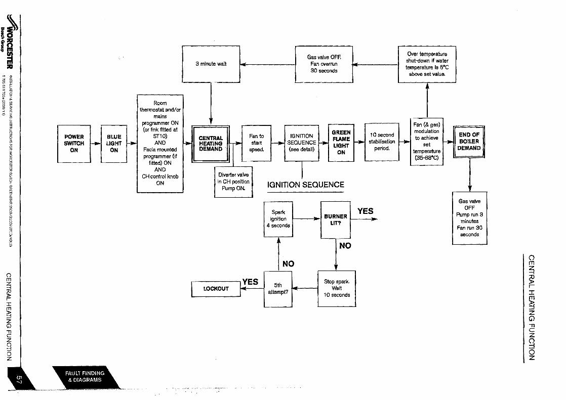
CENTRAL HEATING FUNCTION 57
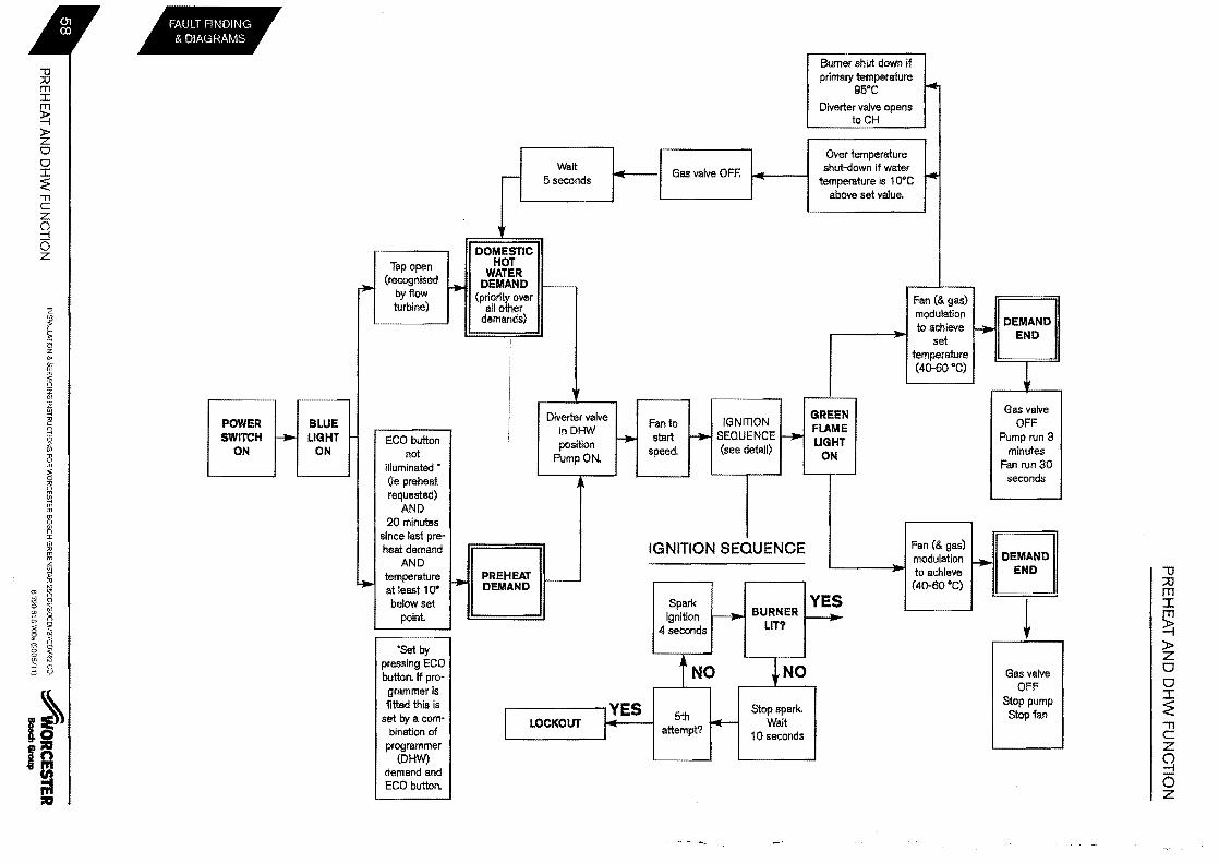
PREHEAT AND DHW FUNCTION 58
PROTECTION FUNCTION 59
INSTALLATION amp SERVICII IIltSTRUCTIONS FOR WORCESTER BOSCH GREENSTAR 25CDil30CDil37CDV42CDi~ORCESTER CONTENTS 6720 613 700 (200611)Bosch Group
SAFETY PRECAUTIONS INSTALLATION REGULATIONS
IF YOU SMELL GAS
x DONT SMOKE OR STRIKE MATCHES
X DONT TURN ELECTRICAL SWITCHES ON OR OFF
V DO PUT OUT NAKED FLAMES
V DO OPEN DOORS AND WINDOWS
V DO KEEP PEOPLE AWAY FROM THE AREA AFFECTED
V DO TURN OFF THE CONTROL VALVE AT THE METER
V TELEPHONE THE NATIONAL GAS EMERGENCY SERVICE ON 0800111999
(IendmorlO A Benchmark Log Book is provided by the manufacturer for the installer to complete
including their CORGI registration number to confirm that the boiler has been installed
commissioned and serviced according to the manufacturers instructions
IMPORTANT The completed Benchmark Checklist will be required in the event of any
warranty work and may be reqUired by the local Building Control Inspector
HEALTH amp SAFETY The appliance contains no asbestos and no substances have been used in the
construction process that contravene the COSHH Regulations (Control of Substances
Hazardous to Health Regulations 1988)
COMBUSTIBLE AND CORROSIVE MATERIALS Do not store or use any combustible materials (paper thinners paints etc) inside or
within the vicinity of the appliance
Chemically aggressive substances such as halogenated hydrocarbons containing
chlorine or fluorine compounds can corrode the appliance and invalidate any warranty
FITTING amp MODIFICATIONS Fitting the appliance and any controls to the appliance may only be carried out by a
competent engineer in accordance with the Gas Safety (Installation and Use)
Regulations 1998
Flue systems must not be modified in any way other than as described in the fitting
instructions Any misuse or unauthorised modifications to the appliance flue or
associated components and systems could invalidate the warranty The manufacturer
accepts no liability arising from any such actions excluding statutory rights
SERVICING Advise the user to have the system serviced annually by a competent qualified
engineer (such as British Gas or CORGI registered personnel) using approved spares
to help maintain the economy safety and reliability of the appliance
IMPORTANT laquo The service engineer must complete the Service Record in the
Benchmark section after each service
Gas Safety (Installation amp Use) Regulations
All gas appliances must be installed by a
competent person in accordance with the above
regulations Failure to install appliances correctly
could lead to prosecution
The appliance must be installed in accordance
with and comply to the curren Gas Safety
Regulations lEE Regulations Building
Regulations Building Standards Scotland
(Consolidation) Building Regulations (Northern
Ireland) local water by-laws Health amp Safety
Document 635 (The Electricity at Work
Regulations 1989) and any other local
requirements
British Standards
The relevant British Standards should be followed
including
BS70741 Code of practice for domestic and hot
water supply
BS6891 Installation of low pressure gas
pipework up to 28mm R1
BS5546 Installation of gas hot water supplies for
domestic purposes
EN 12828 Central heating for domestic premises
BS54401 Rues and ventilation for gas applishy
ances of rated heating not exceeding 70kW (net)
Rues
BS54402 Rues and ventilation for gas applishy
ances of rated heating not exceeding 70kW net
Air Supply
BS7593 Treatment of water in domestic hot
water central heating systems
BS 6798 Installation of gas lired boilers of rated
input up to 70kW net
Where no specific instruction is given reference
should be made to the relevant British Standard
codes of Practice
LPG_ Installation
An appliance using LPG must not be installed in
a room or internal space below ground level unless
one side of the building is open to the ground
limber framed buildings
Where the boiler is to be litted to a timber framed
~WORCESTER INSTALLATION amp SERVICING INSTRUCTIONS FOR WORCESTER BOSCH GREENSTAR 25CovaOCOil37CDV42CDi GENERAL INFORMATION 6720 613 7000 (200611)BolIch Group
TECHNICAL DATA
NATURAL GAS LPG
DESCRIPTION UNITS 25CDi 30CDi 37CDi 42CDi 25CDi 30CDi 37CDi 42CDi
Total boiler weight (lift weight) kg 485 485 485 485 485 485 485 485
Packaged boiler weight kg 57 57 57 57 57 57 57 57
SEDBUK 903 901 901 901 903 901 901 901
INSTALlATION amp SERVICING INSTRUCTIONS FOR WORCESTER BOSCH (lREENSTAR 25CDil3OCDVB7CDil42 CD AORCESTERTECHNICAL DATA 6720 613 700 (200611) Bosch Group
LAYOUT amp COMPONENTS
28middot
27
26 --shy
25 --shy
24middotshy
23 -shy
22
21 ----shy
20
16 -shy
shy ~- 2
shy--shy 3
----_------ ---_
~
4
__ _____________________ 5
6
7
8
9
10
bullbullbullbullbullbullbullbullbullbull 14
The diagram opposite shows the controls in the servicing position and excludes the outer case
FLAME VIEWING WINDOW
2 IGNITION ELECTRODE AND FLAME SENSE ELECTRODE
3 HEAT EXCHANGER
4 OVERHEAT THERMOSTAT
5 ACCESS POINT FOR CLEANING HEAT
EXCHANGER
6 PLATE TO PLATE DHW HEAT EXCHANGER
7 PUMP
8 SYSTEM PRESSURE GAUGE
9 DRAIN POINT 10 MAINS COLD WATER IN
11 CH RETURN 12 CHARGING LINK ASSEMBLY
13 GAS INLET CONNECTION 22 mm COMPRESSION
14 COVER FOR EXTERNAL WIRING
CONNECTIONS
15 CONTROL PANEL IN SERVICE POSITION
16 ACCESS COVER FOR TRANSFORMER
amp PCB
17 DHWOUT
18 CHFLOW
19 TRAP I SYPHON OUTLET CONNECmiddot TION (22 mm PLASTIC PIPE)
20 INLET PRESSURE TEST POINT
21 TRAP I SYPHON
22 GAS VALVE 23 DHW TEMPERATURE SENSOR
24 AIR I GAS ADJUSTMENT SCREW 25 TESTING POINT FOR FAN PRESSURE
26 FAN
27 PRIMARY SENSOR
28 EXPANSION VESSEL 29 REMOVABLE TOP CASE PANEL FOR
43 COLD WATER IN CONNECTION 44 CH RETURN CONNECTION TO SERmiddot
VICE VALVE
45 DIVERTER VALVE 46 PRESSURE RELIEF VALVE
47 COMPACT HYDRAULIC MOUNTING
SCREW (2) TO BOILER
I I
I I
I I
I t t t I I I I
II I
I 40 I
bullbullbullbullbullbullI 46 I I I I bull~
t 45 I I II I 42
I41 bullbullbullbull I 9 ~
~ 43- shyl 48 CH TEMPERATURE CONTROL
I 49 MAINS ONOFF INDICATORDIAGNOSshyI
TIC LIGHT (BLUE)I t 50 DHW TEMPERATURE CONTROL
I 51 CENTRAL HEATING BOOST BUTTON
52 SERVICE BUTTON 53 BURNER ON INDICATOR LIGHT
(GREEN)
54 MASTER SWITCH ONOFF
55 HOLIDAY BUTTON
56 ECO BUTTON
57 FAULT RESET BUTTON 58 SYSTEM PRESSURE GAUGE
59 POSITION FOR OPTIONAL TEXT
DISPLAY WITH INTELLIGENT FUNCmiddot
TIONALITY OR TIMER
60 DISPLAY 6720611027-1010
INSTALLATION amp SERVICING INSTRUCTIONS FOR WORCESTER BOSCH GREENSTAR 25CDi3OCDV37CO42 CD ~ORCESTERLAYOUT amp COMPONENTS 6720 613700 (200611)
1
3
IMPORTANT All the following Pre-Installation sections must be read and requirements met before starting boiler or flue Installation
CAUTION ISOLATE THE MAINS SUPPLIES BEFORE STARTING ANY WORK AND OBSERVE ALL RELEVANT SAFETY PRECAUTIONS
2
I I I I I z==~ I
---
------~
5
CLEANING PRIMARY SYSTEMS
IMPORTANT Debris from the system can damage the boiler and reduce efficiency Failure to comply with the guidelines for the use of water treatment with the applishyance will invalidate the appliance warranty
BEFORE CLEANING THE SYSTEM
ENSURE THE SYSTEM AND PIPEWORK IS
IN GOOD WORKING ORDER
KEEP THE EXISTING BOILER
CIRCULATING PUMP WHERE POSSIBLE
OR USE A POWER FLUSHING MACHINE
TO AID THE CLEANSING PROCEDURE
BEFORE INSTALLING A NEW BOILER
CLEANING THE PRIMARY SYSTEM
Fill the system with cold water and check
for leaks
2 Open all drain cocks and drain the system
S Close drain cocks and add a suitable
flushing agent at the correct strength for
the system condition in accordance with
the manufacturers instructions
Circulate the flushing agent before the
boiler is fired up
4 Run the boilersystem at normal operating
temperature as directed by the manufacturer
of the flushing agent
5 Drain and thoroughly flush the system to
remove the flushing agent and debris
----
I I
I I t I I I
~
4
------C9 ~III
( II I ) I I
_--
I I I I
---
KEY
Valve
Flushing
Agent
~ORCESTER INSTALLATION amp SERViCING INSTRUCTIONS FOR WORCESTER EiCSCH GREFNSTAR 25CDiI3OCDi37COil42CDi CLEANING PRIMARY SYSTEMS 6720 613 700a (200611)BoIIch Group
MAINS SUPPLIES
ELECTRIC SUPPLY
f bull Supply 230V - 50Hz
(See Technical Data for IP ratings)
bull Cable PVC insulated 075mm2
(24 x 02mm) temperature rated to 90C
bull Extemal3A fuse to BS1362
bull The appliance must be earthed
bull All pipes to the boiler must be cross-bonded
bull Wiring must comply with lEE wiring regulashy
tions and any local regulations which may
apply to fIXed wiring to a stationary appliance
GAS SUPPLY
bull Boilers using NG must be connected to a
govemed meter
bull LPG boilers must be connected to a
regulator
bull Installation and connection of the gas supshy
ply to the boiler must be in accordance with
8S6891
bull Under no circumstances should the size of
the gas supply pipe be less than that of the
appliance inlet connection
bull The meter or regulator and pipework to the
meter must be checked preferably by the
gas supplier to ensure it is in good working
order and can meet the gas flow and presshy
sure requirements in addition to the demand
from any other appliance being served This
does not include the pipework from the
meter to the boiler
bull For olive connections we recommend using
gas pipes with minimum 09 mm wall thickness
WATER SUPPLY
Water Mains Pressure
bull Minimum mains water pressure 15 up to
25 bar (see technical data on page 6) for
maximum performance
bull Maximum mains fed water pressure 10 bar
If necessary fit a pressure reducing valve
IMPORTANT Non-return back flow preshyMAINS WATER EXPANSION VESSEL vention devices (including those associatshyA - Mini expansion vessel part No7 716 102 105 ed with water meters) fitted to the mains 8 - Mains water inlet pipe water supply can cause a pressure build C - Non-return valve up which could damage the boiler and D - Boiler other household appliances
bull Where the mains water supply has a nonshy
return back flow prevention valve fitted a
mini expansion vessel (A) should be conshy
nected to the mains water inlet pipe (B) B C between the non-return valve (C) and the
boiler (D) as shown opposite
Us~ in ~ard ~ater ~realgt~ Normally there is no need for water treatment
to prevent scale formation as the maximumII temperature of the DHW heat exchanger is
~RCESTER INSTALLAllON amp SERVICING NSTRUCTIONSFOR WORCESTER BOSCH GREENSTAR 25CovaOCDV37CDV42CO WATER SYSTEMS amp PIPEWORK 6 70 613 700 (200611)
3 4 jl
q JiE
25mm mLn
- H
400mm min
A=- 1 L-J []6Invert ~
C G
M
L
o
N
6720611 927 - 0310
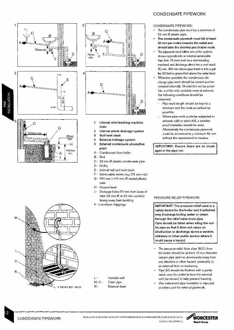
Internal sinkwashing machine drain
2 Internal waste drainage system 3 Soilvent stack 4 External drainage system 5 External condensate absorption
point A - Condensate from boiler
8 - Sink
C - 22 mm 0 plastic condensate pipe
D Gulley
E - Internal soil and vent stack
F - Serviceable waste trap (75 mm min)
G - 300 mm x 100 mm 0 sealed plastic
tube
H - Ground level
J Drainage holes 50 mm from base of
tube (12 mm 0 al 25 mm centres)
facing away from building
K - Limestone chippings
L Outside wall
MOmiddot Drain pipe
N- External drain
CONDENSATE PIPEWORK
CONDENSATE PIPEWORK
bull The condensate pipe must be a minimum of
22 mm 0 plastic pipe
bull The condensate pipework must fall at least 50 mm per metre towards the outlet and should take the shortest practicable route
bull The pipework must follow one of the oplions
shown opposile into an internal serviceable
trap (min 75 mm) such as a sinkwashing
machine) and discharge direct into a vent stack
(E) min 450 mm above pipe inver or into a gulshy
ley (O) below ground bul above the water level
bull Wherever possible the condensate disshy
charge pipe work should be routed and tershy
minated internally Should this not be possishy
ble and the only available route is external
the following conditions should be
observed
Pipe work length should be kept to a
minimum and the route as vertical as
possible
Where pipe work could be subjected to
extreme cold or wind chill a weather
proof insulation should be used
Altematively the condensate pipework
could be increased to a minimum 32 mm
without the requirement 10 insulate
IMPORTANT Ensure there are no blockshyages in the pipe run
PRESSURE RELIEF PIPEWORK
IMPORTANT The pressure relief valve is a safety device for the boiler and if activated may discharge boiling water or steam through the relief valve drain pipe Care should be taken when siting the outshylet pipe so that it does not cause an obstruction or discharge above a window entrance or other public access where it could cause a hazard
bull The pressure relief drain pipe (MO) from
the boiler should be at least 15 mm diameter
copper pipe and run downwards away from
any electrics or other hazard preferably to
an external drain or soakaway
bull Pipe (M) should be finished with a partial
bend near the outlet to face the external
wall (as shown) to help prevent freezing
bull Use waterproof pipe insulation in exposed
positions and for external pipework
INSTALLATiON amp SERVICING INSTRUCTIONS FOR WORCESTER BOSCH GRpoundENSTAR 25COV3OCD137CDil42 COi ~ORCESTERCONDENSATE PIPEWORK 672C 613 700 (2006 1) Bosch Group
above elbow
Using 1 00 mm flue kit -1112mm Using 125 mm flue kit 5mm -1152 mm
600mm front clearance for service
SERVICING CLEARANCES ~_~ BOILER LOCATION amp
+30rrm
200mm
CLEARANCES
This boiler is only suitable for installing internally
within a property at a suitable location onto a fixed rigid non-combustible surface at least the same size as the boiler and capable of supportshy
ing the boiler weight
COMPARTMENTS Follow the requirements of 886798 and 885440 Part 2 and note
bull Minimum clearances must be maintained bull An access door is required to install service
and maintain the boiler and any anCillary
equipment bull If fitting the boiler into an airing cupboard
use a non-combustible perforated material
(maximum hole sizes of 13mm) to separate
the boiler from the airing space
BOILER CLEARANCES The diagram opposite shows the mini space required to install and service the boiler
VENTILATION This is a room sealed appliance and does not require any air for combustion from inside the
property If the appliance is filted into a cupshyboard or a compartment is built around the
appliance after installation then the compartshy
ment must be separated from the boiler space
by a perforated non-combustible partition as
described in 88 6798 Notwithstanding the requirements of B8 6798 and B8 5440 there is no need for ventilation
openings to be provided in the compartment because of the low heat loss from the appliance
casing if the clearances shown are maintained
Do not operate the appliance if the flue terminal filted on the outside wall or roof is obstructed or damaged
The boiler can be installed in zones 2 or 3 If a mechanical or RF mechanical timer or text disshy
play with room thermostat (lp 20 only) is fitted
the boiler can only be installed in zone 3 A Non mechanical timer can be installed in
zone 2 See lEE wiring regulations (See Technical Data for IP ratings)
IMPORTANT any switch or appliance control using 230 V mains electricity must not be able to be touched by a person using the bath or shower
Electrical switches fused spur and socket outlets must not be situated in the bathshyroom
For further information about bathroom installashy
tions please consult Operational Procedures
Part 20 Electricity
2250mm
6 720611927-1310
INSfALLATION amp SERVICING INSfRucnONS FOR WORCESTER BOSCH GREENSfAR 2SCDil3OCD37CD42 CD ~ORCES1ERBOILER LOCATION amp CLEARANCES 6720 613 700a (2006111)
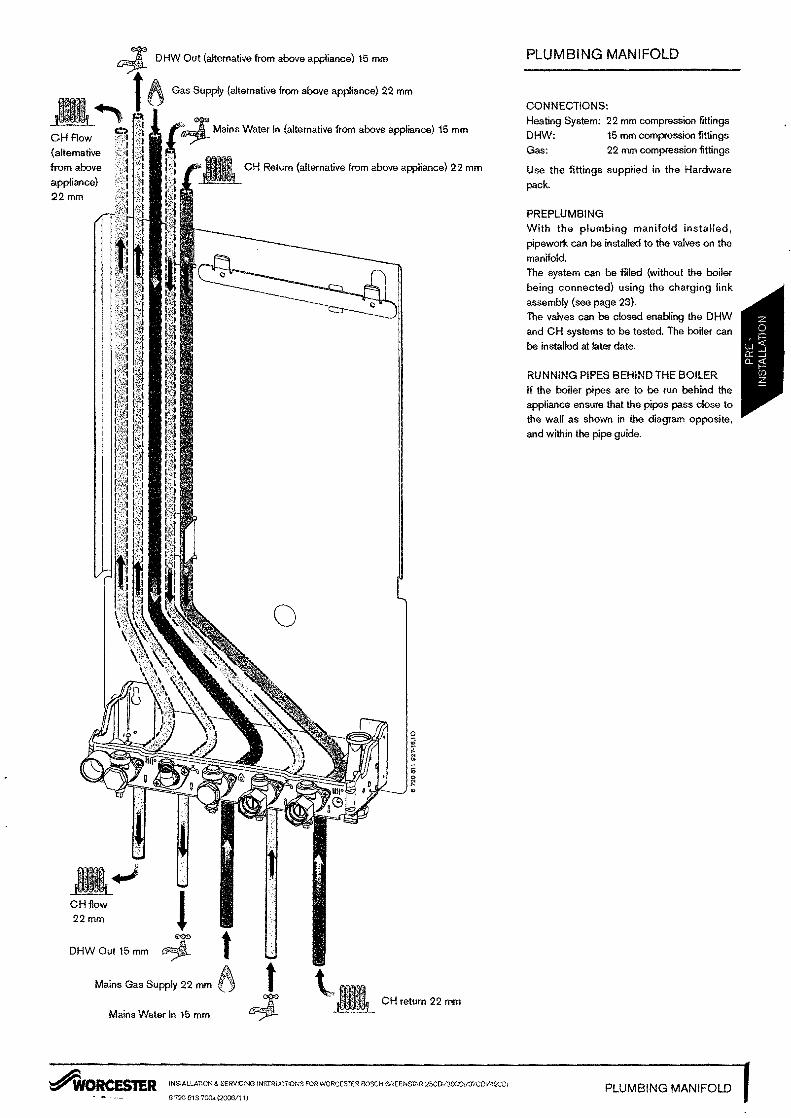
~ DHW Out (alternative from above appliance 15 mm
6 Gas Supply (alternative from above appliance) 22 mm
CHAow (altemative
from above
appliance 22mm
CH return 22 mm
CHfiow 22mm
DHW Out 15mm
Mains Gas Supply 22 mm
Mains Water In 15 mm
CH Return (alternative from above appliance 22 mm
o
PLUMBING MANIFOLD
CONNECTIONS
Heating System 22 mm compression fittings
DHW 15 mm compression fittings
Gas 22 mm compression fittings
Use the fittings supplied in the Hardware
pack
PREPLUMBING With the plumbing manifold installed pipework can be installed to the valves on the
manifold
The system can be filled (without the boiler being connected using the charging link
assembly (see page 23) The valves can be closed enabling the DHW and CH systems to be tested The boiler can
be installed at later date
RUNNING PIPES BEHIND THE BOILER If the boiler pipes are to be run behind the appliance ensure that the pipes pass close to the wall as shown in the diagram opposite
Minimum dimensions of flue terminal positions for balanced room sealed flues with
fanned draught
bull The flue must be filted and terminated in
accordance with the recommendations of
8S5440 Part 1
DRWG REF
TERMINAL POSITION DISTANCE
A
8
C
Directly below an opening air brick opening windows etc
Above an opening air brick opening window etc
Horizontally to an opening air brick opening window etc
300mm
300mm
300mm
D Below gutters soil pipes or drain pipes 75mm
E Below eaves 200mm
F
G
Below balconies or car port roof (lowest point)
From a vertical drain pipe or soil pipe
200mm
150mm
H From an internal or extemal corner 300mm
I Above ground roof or balcony 300mm
J From a surface facing the terminal 600mm
K From a terminal facing the terminal 1200mm
L From an opening in the car port (eg door window) into the dwelling 1200mm
M Vertically from a terminal on the same wall 1500mm
N Horizontally from a terminal on the same wall 300mm
0 From a non combustible vertical structure on the roof P Above intersection with roof 0 Adjacent to windows or openings on pitched and flat roofs 600mm
R Below windows or openings on pitched roofs 2000mm
bull The flue must not cause an obstruction
bull Discharge and any noise from the flue outlet
must not cause a nuisance
bull Flue gases have a tendency to plume and in
certain weather conditions a white plume of
condensation will be discharged from the
flue outlet Where this could be a nuisance
for example near security lighting an altershy
nate position should be found
bull The air inletoutlet duct and the terminal of
the boiler must not be closer than 25mm to
any combustible material
Detailed recommendations on protection of
combustible materials are given in
BS 54401
bull A protective terminal guard must be fitted if the terminal is 2m or less above a surface to
which people have access
The guard must be spaced equally (minishy
mum 50 mm) around the flue and fixed to
the wall with plated screws See Contact
Information (inside front cover)
In addition the terminal should not be nearer than 150mm (fanned draught) to an opening
in the building fabric formed for the purpose of accommodating a built-in element such as a
window frame
2 Not recommended
See instructions supplied with vertical Hue kits
INSTALLATION amp SERVICING INSTRUCTIONS FOR WORCESTER BOSCH GREENSTAR 25CDi3OCOiI37CDV42 COl ~ORCESTERFLUE TERMINAL POSITIONS 6720513700 (2006111)
STANDARD FLUE HORIZONTAL
0100
MAX 686 mm A x1
MIN 250 mm A x l
0125 MAX 1070 mm Ax 1
MIN 250 mm Ax l
bull Requires cutting
MAXIMUM FLUE HORIZONTAL
0100middot10000 mm
Ax 1 + B x 10
0125middot 23000 mm
Ax 1 + B x 23
MAXIMUM FLUE VERTICAL START + 1 BEND
FQq IpA L---~~~ B
() C
0100middot10000 mm
Ax1+Cxl+Bx11 + Fx 1
0125middot23000 mm
A x 1 + C x 1 + B x 23 + F x1
MAXIMUM FLUE HORIZONTAL + 1 BEND
[ OJ B
o C
0100 8000 mm
Ax1 + Bx9+Cxl
0125 21000 mm
A x 1 + B x 21 + C x1
MAXIMUM FLUE VERTICAL START + 2 BENDS
F 61 QIE9A BC==zi
cO 0100 - 8000 mm A J( 1 + C x 2 + B x 10
+ Fxl
0125middot21000 mm
A x 1 + C x 2 + B x 22
+ F x 1
MAXIMUM FLUE VERTICAL START + 3 BENDS
F bl q middotLEiP B C==-=J
C ()
0100 bull 6000 mm
Axl+Cx3
+Bx9+Fx1
0125middot19000 mm
Ax1 +Cx3
+ Bx21 + Fxl
MAXIMUM FLUE VERTICAL WITH 2 X 45deg BENDS
E
B
o
0100middot9500 mm (including terminal)
B x 10 + 0 x 2 + Ex 1
0125middot21000 mm (including terminal)
Bx21 + Dx2 +Ex1
VERTICAL FLUE WITH 2 X 90 BENDS
E 5 B ~=-=-l
C 0 0100 7500mm
(including terminal)
Bx9+ Cx2 +Exl
0125 - 19000 mm (including terminal)
Bx20+ Cx2 +Ex1 6120 611 927-0810
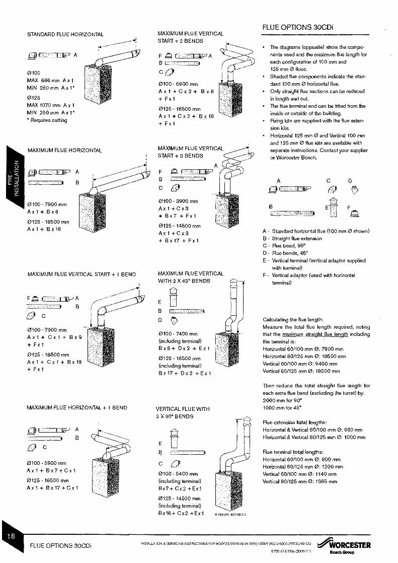
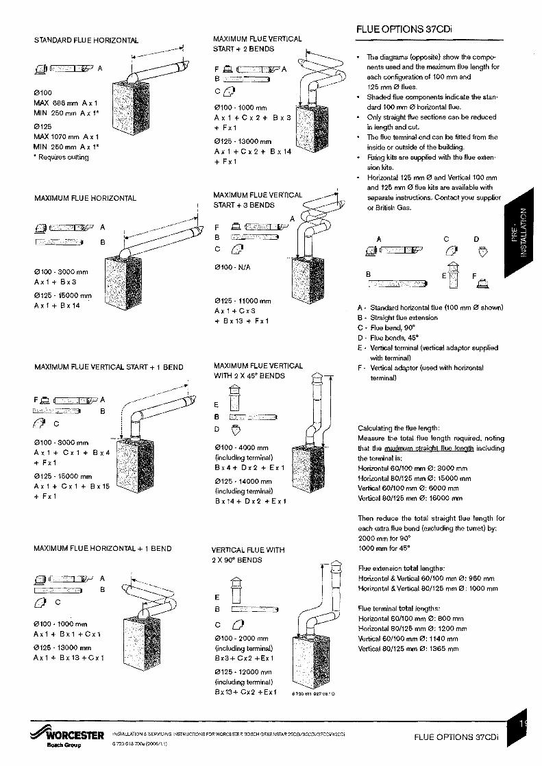
FLUE OPTIONS 25CDi
bull The diagrams (opposite) show the composhynents used and the maximum flue length for each configuration of 100 mm and 125 mm 0 flues
bull Shaded flue components indicate the stanshydard 100 mm 0 horizontal flue
bull Only straight flue sections can be reduced in length and cut
bull The flue terminal end can be fitted from the inside or outside of the building
bull Fixing kits are supplied with the flue extenshy
sion kits
bull Horizontal 125 mm 0 and Vertical 100 mm and 125 mm 0 flue kits are available with separate instructions Contact your supplier
or Worcester Bosch
A C o f) V
B F C middotmiddotmiddotmiddotmiddotmiddotmiddotmiddotmiddotmiddotltmiddotmiddot1 bd
Amiddot Standard horizontal flue (100 mm 0 shown) Bmiddot Straight flue extension
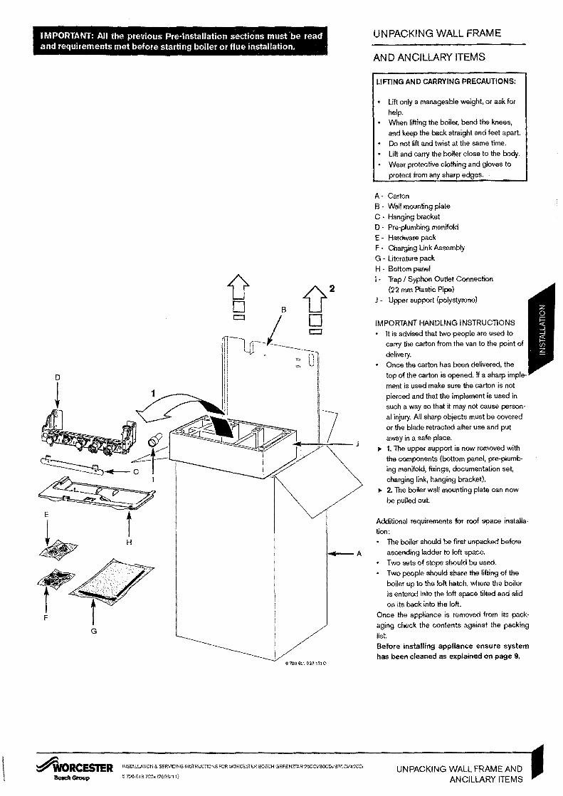
IMPORTANT All the previous Pre-Installation sections must -be read UNPACKING WALL FRAME and requirements met before starting boiler or flue installation
AND ANCILLARY ITEMS
J o B
G
LIFTING AND CARRYING PRECAUTIONS
bull Lift only a manageable weight or ask for
help
bull When lifting the boiler bend the knees
and keep the back straight and feet apart
bull 00 not lift and twist at the same time
bull Lift and carry the boiler close to the bcdy
bull Wear protective clothing and gloves to
protect from any sharp edges
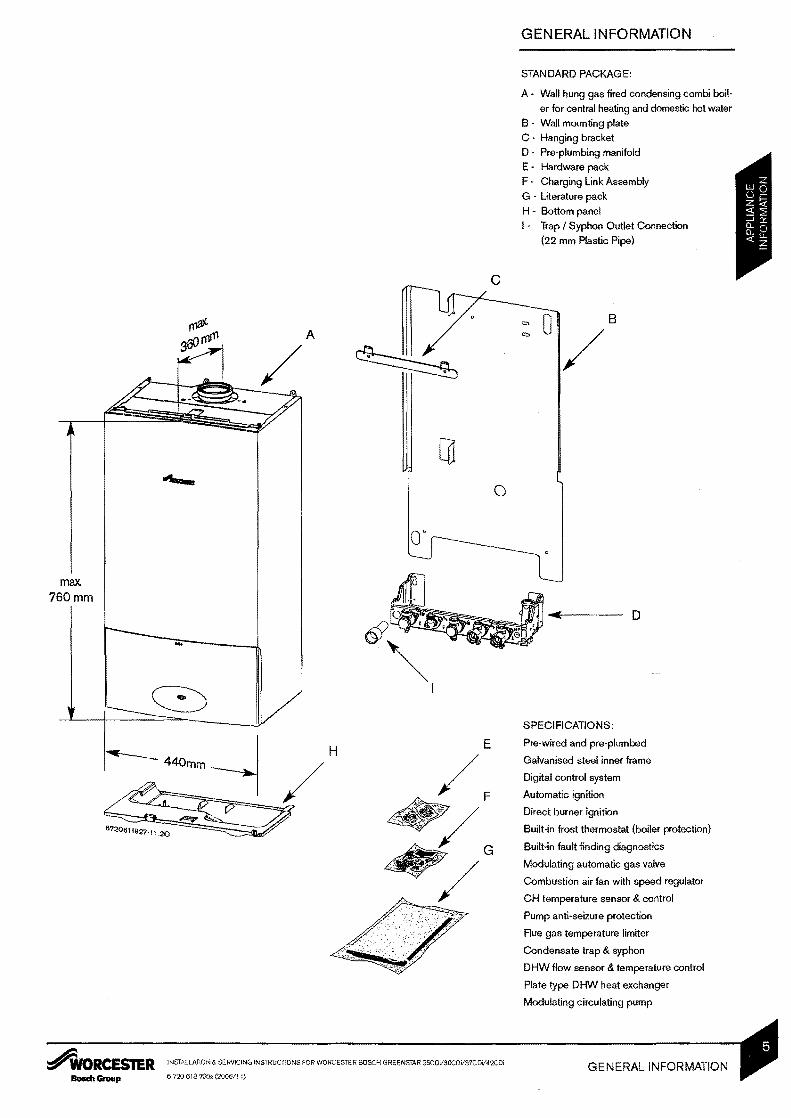
A - Carton
B - Wall mounting plate
C - Hanging bracket
D - Pre-plumbing manifold
E - Hardware pack
F - Charging Link Assembly
G - Literature pack
H - Bottom panel I - Trap I Syphon Outlet Connection
(22 mm Plastic Pipe)
J - Upper support (polystyrene)
IMPORTANT HANDLING INSTRUCTIONS
bull It is advised that two people are used to carry the carton from the van to the point of
delivery
bull Once the carton has been delivered the
top of the carton is opened If a sharp impleshy
ment is used make sure the carton is not
pierced and that the implement is used in
such a way so that it may not cause personshy
al injury All sharp objects must be covered
or the blade retracted after use and put
away in a safe place
~ 1 The upper support is now removed with
the components (bcttom panel pre-plumbshy
ing manifold fixings documentation set
charging link hanging bracket)
~ 2 The bciler wall mounting plate can now
be pulled out
Additional requirements for roof space installashy
tion
bull The boiler should be first unpacked before
ascending ladder to loft space
bull Two sets of steps should be used
bull Two people should share the lifting of the
bciler up to the loft hatch where the boiler
is entered into the loft space tilted and slid
on its back into the loft
Once the appliance is removed from its packshy
aging check the contents against the packing
list
Before installing appliance ensure system has been cleaned as explained on page 9
INSTALLATION amp SERVICING INSTRUCTIONS FOR WORCESTER BOSCH GREENSTAR 25CDiI3OCDV37CDV42CDi~ORCESTER UNPACKING WALL FRAME AND 6720613100 (2006(11)BoedIGroup ANCILLARY ITEMS
10mm0
min5mm
~ I ~-- ~
I
I I
I I
I I
I I
I I
en ~ o
WALL MOUNTING PLATE
FLUE OPENING
CAUTION Ensure there are no pipes elecshy
tric cables damp proof courses or other
hazards before drilling
SAFETY
All relevant safety precautions must be ufldershy
taken Protective clothing footwear gloves and
safety goggles must be wom as appropriate
FIXING THE POSITION OF THE WALL
MOUNTING PLATE
bull The diagram opposite shows the relative
positions of the flue and the fIXing of the wall
mounting plate the mounting plate and preshy
plumbing manifold
Igt Place the wall mounting plate against the
wall in the desired position
Igt Mark 3 fixing points through the holes (A B
C) in the wall mounting plate
Igt Drill the 3 holes for wall mounting plate wall
hanging bracket and pre-plumbing manifold
Secure wall mounting plate with hanging
bracket with 3 screws (supplied with the
boiler) Do not fully fasten the lower 2
screws
Use the horizontal slots in the wall mounting
plate to level the hanging bracket mark the
4th hole and drill
Igt Fi)( and secure the hanging bracket with
C both screws
FLUE OUTLET
Follow the diagram opposite to mark the
centre of the flue for rear outlet (1 amp 2) or
for side outlet (2 amp 3)
Note increase this height by 52 mm for
every 1000 mm of horizontal length that the
flue outlet is away from the boiler
Igt For the 60100 mm 0 flue make a 125 mm
diameter hole through the wall using a core
drill or similar
For flues using an optional weather collar
fitted from inside the building make a
150 mm 0 hole
Clear away any debris
FIXING THE PRE-PLUMBING MANIFOLD
Mount the pre-plumbing manifold on the 2
lower screws and secure the screws
o
INSTALLATION amp SERVICING INSTRUCTIONS FOR WORCESTER BOSCH GREENSTAR 25C0iI3OC0il37CDil42 co ~ORCESTERWALL MOUNTING PLATE 6720 613 700 (2006il11) Bosch GrouPFLUE OPENING
CHARGING LINK
(FILLING LOOP)
In order to fill or flush the system prior to the
boiler being hung you must use your r~-usable
System Filling Kit - Part Number 7716 192 282 Fully close the isolating valves on both the
DHW inlet and CH return connections
Check that the gas and water connections
are tight
11 Unscrew the blanking plugs from both
the DHW inlet and CH return connections
Place the filter inside the inlet side of the
Charging Link ensuring that the filter mesh
is inside the inlet
Fit the Charging Link assembly onto the
DHW inlet and CH return connections
Do not insert the Charging Key at this stage
12 Ensure that the Charging Link is pushed
in fully to the stop tabs on both sides of the
Charging Link
Fit two M4 screws complete with washers
to each of the two connections NB It is not
possible to access the third screw hole so
this can be left
o Do not attempt to turn the brass hexagon
connectors
13 Ensure that the white plastic Control
Screw on the Charging Link is turned fully
into its closed position see diagram (13) Open the isolating valves on both the DHW
inlet and CH return connections
Insert the Charging Key initially aligning the
arrow on the key with the middotunlock symbol
on the Charging Link body Ensure that the
key is inserted fully and turn to the lock
position Check that the key is secure see
diagram (13) To fill the system from the DHW inlet tum
the white plastic Control Screw on the
Charging Link to the fully out position
Once the system has been filled turn the
white Control Screw to its closed position
and then remove the Charging Key by tummiddot
ing back to its unlock position and withmiddot
CH Return drawing Store the Charging Key in the clip
provided on the inside of the bottom panel bull ~~ Connection
~ Blanking Plug fP~-
~ (j
1 Stop Tab
middot~~~~~~~-L~--~ DHW Inlet
AsSembly ~Charging Key
I I
I-~-raquo= Filter I
~WORCESTER INSTALLATION amp SERVICING INSTRUCTIONS FOR WORCESTER BOSCH GREENSTAR 25CDil3OCDi37CDV42CD CHARGING LINK (FILLING LOOP) 6 720 613 700 (200611)
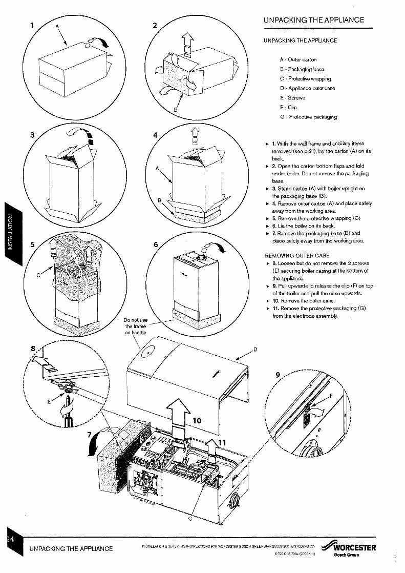
UN PACKI NG TH E APPLIANCE
UNPACKING THE APPLIANCE
A bull Outer carton
8 Packaging base
C Protective wrapping
D Appliance outer case
Emiddot Screws
F Clip
G Protective packaging
Itgt 1 With the wall frame and ancillary items
removed (see p21) lay the carton (A) on its
back Itgt 2 Open the carton bottom flaps and fold
under boiler Do not remove the packaging
base
Itgt 3 Stand carton (A) with boiler upright on
the packaging base (8)
Itgt 4 Remove outer carton (A) and place safely
away from the working area
Itgt 5 Remove the protective wrapping (C)
Itgt 6 Lie the boiler on its back
Itgt 7 Remove the packaging base (8) and
place safely away from the working area
REMOVING OUTER CASE
Itgt 8 Loosen but do not remove the 2 screws
(E) securing boiler casing at the bottom of
the appliance
Itgt 9 Pull upwards to release the clip (F) on top
of the boiler and pull the case upwards
Itgt 10 Remove the outer case
Itgt 11 Remove the protective packaging (G)
from the electrode assembly
INSTALLATION amp SERVICING INSTRUCTlOgtlS FOR WORCESTER BOSCH GREENSTAR 25CDil3OCOil37COil42 co ~ORCESTERUNPACKING THE APPLIANCE 6720 613 700a (200611) BosdIGraup
Do not lilt by the top case panel
I I
I~ 4A------
I
I I I I
I I
I I I
FITTING TH E APPLIANCE
BOILER CONNECTIONS
CAUTION ISOLATE THE MAINS GAS SUPPLY BEFORE STARTING ANY WORK AND OBSERVE ALL RELEVANT SAFETY
PRECAUTIONS
GAS AND WATER CONNECTIONS
System pipes may be run vertically upwards
behind the boiler or below it See Plumbing
Manifold Section on page 15
A CH flow (22 mm)
B bull CH return (22 mm)
C - Gas inlet (22 mm)
o DHW outlet (15 mm)
Emiddot Mains water inlet (15 mm)
1 Fit sealing washers to service valves
before hanging boiler
Remove dust caps from connections on
boiler
IMPORTANT Before hanging the boiler
the wall mounting plate ensure that the
sure relief valve connection is in the
position This is located on the right hand
of the wall frame at the rear
2 Pull the extended tabJlever forward and
down until there is no further travel
3 Hang the boiler on to the hanging brackmiddot
et The lugs pass through the rectangular
holes in the boiler back panel
Take care not to disturb the washers on the
connections
NOTE It is recommended that this lifting 22mm 15mm 22mm 15mm 22mm I I
operation is carried out by 2 peopleII _------- ~ observing all precautions for the safe lifting
r 2 I of heavy objects
I Do not lift by the top case panel There are fl---rmiddotmiddotmiddotmiddott I Ii I l two handling holes incorporated into the I f inner casing left and right in the lower secK1G ----------1 r--i I tion of the appliance I
I I 4 Lower the control panel into the service I I
I I position by removing the screw (X) from the I I retaining bracket I I I 5 Make connections to the heating system I I
I shy -- Connect the gas supply to the boiler gas
I I I cock 22 mm compression I I I I Connect mains water in and DHW out I I I I I I I I - --
IMPORTANT The pressure relief connectorI 6 I I must be repositioned after the boiler has been I I I I correctly mounted to the wall mounting plate I 1(
I
6 Push the lever on the pressure relief COnshyI I I II nector UP until the stop on the inside of the~~ ___________J f I ~
~- I [ handle is over the shoulder of the metal 1 I _v A I bracket to secure in place 22mm 15mm 22mm 15mm 22mm I ~
I
I I
I
J~ _ ~ _-_
INSIILLATION amp SERVICING INSTRUCTIONS FOR WORCESTER BOSCH GREENSTAR25COiJ30CDV37CDil42COi~WORCESTER FInING THE APPLIANCE 6720613700 (200611 I)801Icto Group BOILER CONNECTIONS
Edge ofmiddot middot_middot__middot-middot_middot_middot_middot_middot_middot case I
1- 220 mm---3I
52mm
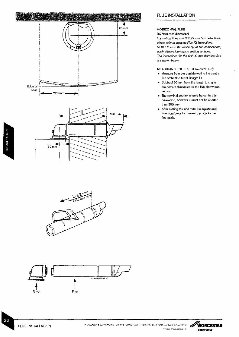
FLUE INSTALLATION
HORIZONTAL FLUE
(60100 mm diameter) For vertical flues and 801125 mm horizontal flues
please refer to separate Rue Kit instructions NOTE to ease the assembly of flue components
apply silicone lubricant to sealing sudaces The instructions for the 601100 mm diameter flue
ONLY CUT EXTENDED FLUE LENGTHSQI PI~~ II ~[ib=l ~ As with the Standard Rue measure from the
outside wall to the centre line of the flue turshy
t ret (length L) ~ Subtract the usable length of the standard
Clamp flue (634 mm) from length L
~ Subtract the usable length of the turret
(52 mm) from length L ~ Subtract 960 mm for each full length extenshy
sion from the figure
~ Cut one of the extensions to the remainder
~ Cut both tubes square taking care not to distort
the tubes
~ Remove any burrs
2380mmII( EXAMPLE
I Length L 2380mm
Subtract Standard Flue -634mm[ip Subtract Turret -52mmgJ CJ ~ I
I I Subtract Full Extension -96Qmm
Cut Length 734mmit i t I t I t 52mm 960mm 734mm 634mm Turret Extension Cut Length Standard Rue
Required Length
rmiddotmiddotmiddotmiddotmiddotmiddotmiddotmiddotmiddotmiddotmiddot NOTE Where extensions are reduced cut
~ length which DQES NOT contain the seal
Seal
I 94mm I I 94mm I I I I I I I I ADDITION OF FLUE BENDS
When flue bends are being used an allowance
of 94 mm per bend must be allowed from the I I 6 72Q611 021Q510
centre line of the bend In the example shown
using a flue extension (960 mm) with 2 bends
will achieve a total length of 1148 mm
~WORCESTER INSTAUATION amp SERVICING INSTRUCTIONS FOR WORCESTER EIOSCH GREENSTAR 25COil3OCDiI37C0i42CDl FLUE INSTALLATION erlO e1 S 700 (2006111) --
FLUE INSTAllATION A Standard Flue
B Intemal Wall Seal ASSEMBLING THE FLUE
C External Wall Seal 1 Slide inner collar (B) onto terminal (A)
2 Additional extensions or bendsDmiddot Clamp
Push fit all extensionsbendsterminal
together and secure connections with
clamps (D) The slope of the terminal outlet
must face downwards
FITTING THE FLUE
3 Fit the terminal (A) through the flue opening
in the wall exposing the plastic outlet
section Ie the outside and fit the outer
flue collar ( C ) over the notches to secure
4 Assemble turret to boiler using the three
screws (see below)
Note Screws are in boiler or in flue kit
E Extension Duct
o
A B
C
E
This screw should be fitted last for
easier installation
FITTING THE TURRET
Aue turret should push directly down and
not be twisted into correct position
Fit turret onto appliance and retain with
three screws
NOTE The clamping plate flat should be at
the rear of the appliance
ADDITIONAL NOTES AND REMINDERS
bull Ensure that all cut lengths are square and
free from burrs
bull The flue when assembled is fully sealed
and components are pushed home
bull The flue is set at an angle of 3deg or 52 mm
per additional 1 m length of extension used
------------- Aat at back
This screw should ----+ be fitted last for
easier installation
INSTALLATION amp SERVICING INSTRUCTIONS FOR WQRCESTER BOSCH GREENSTAR 25CDV30CDi37CDV42 CDi ~RCESTERFLUE INSTALLATION 6720613700 (200611) Bosch Group
CONDENSATE CONNECTION
Never terminate or discharge into any open source including sink bath shower bidet toilet etc
Note any external condensate pipe work of excessive runs should be protected with weather resistant insulation to help prevent freezing
Ensure that the condensate drain is 22 mm
diameter plastic pipe It must fall at least
60 mm per metre towards the outlet
bull An adapter (A) in 22 mm pipe is contained
in the fitting pack
~ORCESTER INSTALLAno amp SERVICING INSTRUCTIONS FOR WORCESTER BOSCH GREENSfAR 25CDlISOCDilS7CD1I42CDi CONDENSATE CONNECTION 6720 613 700 (200611)BOIlIdI Group
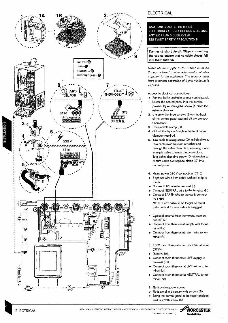
ELECTRICAL
l--~~~A CAUTION ISOLATE THE MANS
I ELECTRICITY SUPPLY BEFORE STARTING I ANY WORK AND OBSERVE ALL RELEVANT SAFETY PRECAUTIONS
I I I
_
EARTH =0 LIVE
NEUTRAL =4) SWITCHED LIVE = (i)
7 ~~---- - FROST 0
tTHERMOSTAT f-~
I
~
_- - -shy
Danger of short circuit When connecting the cables ensure that no cable pieces fall
into the H eatronic
Note Mains supply to the boiler must be through a fused double pole isolator situated adjacent to the appliance The isolator must have a contact separation of 3 mm minimum in all poles
Access to electrical connections
Remove boiler casing to access control panel 1 Lower the control panel into the service I position by removing the screw (X) from the
retaining bracket I I 2 Unscrew the three screws (B) on the back
I of the control panel and pull off the connecshy
tions cover
3 Unclip cable clamp (C)
4 Cut off the tapered cable entry to fit cable
diameter required
5 Turn cable retaining screw (D) anti-clockwise
Run cable over the main crossbar and
through the cable clamp (C) ensuring there
is ample cable to reach the connectors
Turn cable clamping screw (D) clockwise to
secure cable and replace clamp (C) into
control panel
6 Mains power 230 V connection (ST10)
Separate wires from cable end and strip to
6mm
Connect LIVE wire to terminal (L)
Connect NEUTRAL wire to the terminal (N)
Connect EARTH wire to the earth connecshy
tor -=l-) NOTE Earth cable to be longer so that it
pulls out last if mains cable is snagged
7 Optional external frost thermostat connecmiddot
tion (ST6)
Connect frost thermostat supply wire to tershy
minal (Fs)
Connect frost thermostat return wire to tershy
minal (FR)
8 230V room thermostat andor external timer
(ST10)
Remove link
Connect room thermostat LIVE supply to
terminal (Ls)
Connect room thermostat LIVE return to tershy
minal (LR)
Connect room thermostat NEUTRAL to tershy
minal (Ns)
9 Refit control panel cover
Refit panel and secure with screws (B)
Bring the control panel to its upper position
and fIX it with screw (A)
INSTALLATION amp SERVJCING INSTRUCTIONS FOR WORCESTER BOSCH (JREENSTAR 25CDi3OCOi37COV42 COi AIoRCESTERELECTRICAL 6720 613700a (200611)
POSITION OF WIRED
COMPONENTS
GAS VALVE
--SAFETY SOLENOI
SAFETY SOlENOI
MAINS SUPPLY
I 230 V ROOM STATI
P~ROGR~E~ ________ -- --ltt--- - I~- - ----- I
I I
CH TEM- _ -J _ PERATURE~ CONTROL
FlOWNTC
FLUE OVERHEAT
STAT
- FLOW
TURBINE
~~~ ~~------~--------~--H---------+-~-t~r-~
DHW SENSOR
o ST5
ST10 mIi 15 Fuseslow
A AC 230 VSPARK TRANSFORMER
~ 230 V EXTERNAL
FROST STAT (OPTIONAl)
Fuse slow T 05 A
~
6 720612 485middot011 0
~WORCESTER INSTALLATION amp SERVlCIN61NSTRUCTIONS FOR WORCESTER BOSCH GREENSTAR 25COil30CDil37COil42CO POSITION OF WIRED Boa Group 6720 63 700a (200611) COMPONENTS
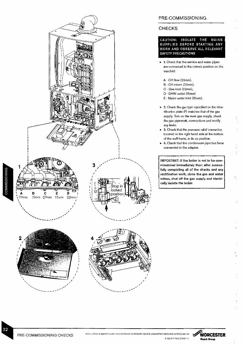
PRE-COM MISSIONI NG
I A 22mm 15mm 22mm 15mm 22mm I
I I I
~ ~
tII
~ - --
I I
CHECKS
CAUTION ISOLATE THE MAINS SUPPLIES BEFORE STARTING ANY WORK AND OBSERVE ALL RELEVANT SAFETY PRECAUTIONS
1 Check that the service and water pipes
are connected to the correct position on the
manifold
A bull CH flow (22mm)
B bull CH return (22mm)
C Gas inlet (22mm)
D DHW outlet (15mm)
E Mains water inlet (15mm)
2 Check the gas type specified on the idenmiddot
tification plate (F) matches that of the gas
supply Turn on the main gas supply check
the gas pipe work connections and rectify
any leaks
3 Check that the pressure relief connector
located on the right hand side at the bottom
of the wall frame in its up position
4 Check that the condensate pipe has been
connected to the adapter
IMPORTANT If the boiler is not to be comshymissioned immediately then after sucessshyfully completing all of the checks and any rectification work close the gas and water valves shut off the gas supply and electrishycally isolate the boiler
- -_ ~
I I
iNSTALLATION amp SERVICING INSTRUCTIONS FOR WORCESTER BOSCH GREENSTAR 25COi30COi13COi42 CDi ~ORCESTERPRE-COMMISSIONING CHECKS 6720613700 (2oo6fl1) BOlCh Group
I
FILLING THE SYSTEM
Ensure all system and boiler drain points are
closed
2 Remove the bottom panel (if fitted) ----- 3 Ensure that the white plastic control screw
I bull r--- I (C) on the charging link is turned fully into 1 iI its closed position ~ I C I 4 Open the isolating valves on both the DHW
I I E inlet and CH return connections
I ~------------~-----__ ~ 5 Insert the charging key (0) (situated in its I D 1 = I I storage position (E) on the bottom cover of I rr I the boiler) initially aligning the arrow on the I _ I key with the unlock symbol on the chargshyI _-_ - I
ing link body Ensure that the key is inserted I I fully and turn to the lock position Check I that the key is secure I - _--- 6 To fill the system from the OHW inlet turn
the white plastic control screw (C) on the
charging link to the fully out position
7 Once the system has been filled to a presshy
sure of 1 bar turn the white control screw
(C) to its closed position
S Vent all radiators retighten when completed
and check the system and correct any leaks
bull The boiler integral expansion vessel is
precharged to 075 bar (equal to a static
head of 75 meters [22 flj) A Schraeder
type valve is filled to the expansion vessel to
allow for pressure adjustment if required
bull If an extra expansion vessel is fitted to the
central heating return adjust to the same
pressure as the appliance internal expanshy
sion tank refer to separate instructions with
the extra expansion vessel
9 Briefly open the pressure relief valve to test
its operation
10 Refill the system up to 1 bar Turn the white
control screw (C) to its closed position and
then remove the charging key by turning
back to its unlock position and withdrawshy
ing
11 Place the charging key (0) in its storage
position (E) on the bottom cover of the boilshy
er
GAS SUPPLY
Open gas cock on the boiler and purge the
gas supply to the boiler ensuring that the
room is well ventilated
Test gas supply for soundness as described
in BS 6891
I I I I I I I I I I I I I I I I I I I I I I I I I
~ORCESTER INSTALLATION amp SERVICING INSTRucnONS FOR WORCESTER BOSCH GREENSTAR 25C Dil3OCDY37C DV42COi FILLING THE SYSTEM 6 720 613 700a (20061 11)BoIch Group
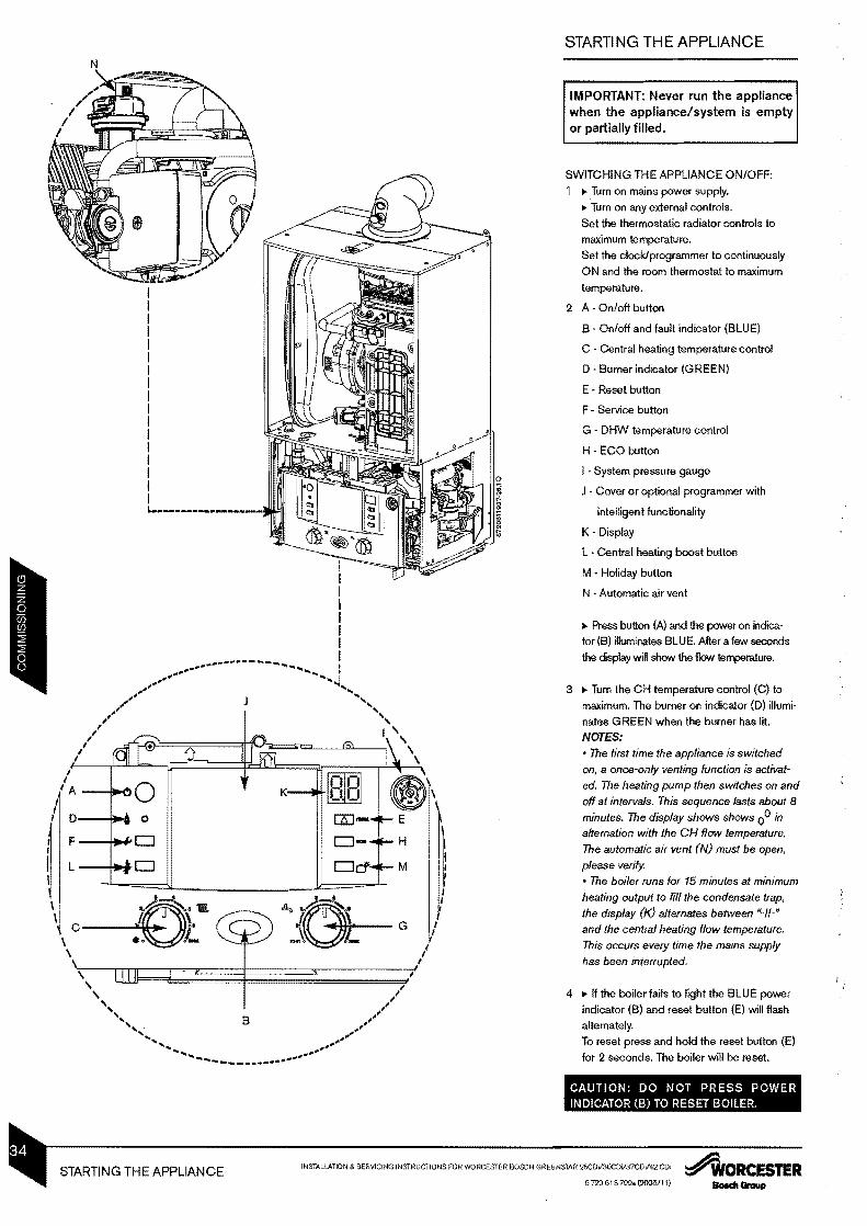
STARTING THE APPLIANCE
IMPORTANT Never run the appliance when the appliancesystem is empty or partially filled
N
A --Q~O I 0---+ o
F--+II+D
L D
1 ~J~bullbull c----j~ bull 1_
I I
II
SWITCHING THE APPLIANCE ONOFF
Turn on mains power supply
Turn on any external controls
Set the thermostatic radiator controls to
maximum temperature
Set the clockprogrammer to continuously
ON and the room thermostat to maximum
temperature
2 A - Onoff button
B - Onoff and fault indicator (BLUE)
C Central heating temperature control
o -Burner indicator (GREEN)
E bull Reset button
F - Service button
G - DHW temperature control
H ECO button
I bull System pressure gauge
J Cover or optional programmer with
intelligent functionality
K - Display
L Central heating boost button
M bull Holiday button
N bull Automatic air vent
Press button (A) and the power on indicamiddot
tor (B) illuminates BLUE After a few seconds
the display will show the flow temperature
3 Turn the CH temperature control (C) to
maximum The burner on indicator (D) illumishy
nates GREEN when the burner has lit
NOTES bull The first time the appliance is switched
on a once-only venting function is activatshy
ed The heating pump then switches on and
off at intervals This sequence lasts about 8
minutes The display shows shows 00 in
alternation with the CH flow temperature
The automatic air vent (N) must be open
please verify
bull The boiler runs for 15 minutes at minimum
heating output to fill the condensate trap
the display (10 alternates between _1_
and the central heating flow temperature
This occurs every time the mains supply
has been interrupted
4 If the boiler fails to light the BLUE power
indicator (B) and reset button (E) will flash
alternately
To reset press and hold the reset button (E)
for 2 seconds The boiler will be reset
CAUTION DO NOT PRESS POWER INDICATOR (B) TO RESET BOILER
INSTALLATION amp SERVICING INSTRUCTIONS FOR WORCESTER BOSCH GREENSTAR 25CDil3OCDi37COil42 CDi ~ORCESTERSTARTING THE APPLIANCE 6 720 613 700a (20061 1)
2
3
4
F
~~---- fD ~D _ 1
Iitrt - -
KEY Valve
Flushing
Agent
Inhibitor
H
I
I
I I
I I - r I
~ I M ---------11
--- LT I
7
- I __ I
N
--------______1
~
p
I I
WATER TREATM ENT
IMPORTANT Debris from the system can
damage the boiler and reduce efficiency
Failure to comply with the guidelines for
the use of water treatment with the appli shy
ance will invalidate the appliance warranty
ENSURE THAT THE SYSTEM HAS BEEN
CLEANED AS ON PAGE 9 OF THESE
INSTRUCTIONS
FLUSHING (Central Heating) 1 Igt Switch off the boiler (A)
Igt Open all drain cocks (B) and drain the
system (C) while the appliance is hot
2 Igt Close drain cocks (D) and add a suitable flushing agent (E) at the correct strength for the system condition in accordance with the manufacturers instructions
3 Igt Run the boilersystem at normal operating temperature (F) for the time stated by the
manufacturer of the flushing agent (G) 4 Igt Drain (H) and thoroughly flush the system
to remove the flushing agent and debris (I)
INHIBITOR (Central Heating) 5 Igt Check drain cocks are closed (J) and all
radiator valves are open (K) before adding a
suitable inhibitor (or combined inhibitor
anti-freeze if the system is exposed to freezshy
ing conditions) to the heating system water
(L) in accordance with the manufacturers
instructions
6 Igt Fill via the built-in filling loop to between 1
and 2 bar using the filling key (M)
7 IIgt Vent all radiators retighten vents when
complete (N)
8 Igt Re-pressurise if necessary to 1 bar (a) Igt Set all controls to maximum (R)
Igt Record the date when the inhibitor was
added to the system on the guarantee card
NOTE The concentration level of inhibitor in the system should be checked every 12 months or sooner if system content is lost
The addition of sealing agents to the system water is not recommended as this can cause problems with deposits left in the heat
exchanger
compatible with aluminium The pH value of the system water must be less than 8 or the appliance guarantee will be invalidated
~WORCESTER INSTAlLATION amp SERVICING INSTRUCTIONS FOR WORCESTER BOSCH GREENSTAR 25CDV3OCDV37CDV42CDi WATER TREATMENT 6720613 700a (200611 1)BOIICII Group
A 0
I I
D 0I
F 0
L 0
0r C lt1 0_
NOTE When running in the central heating boost mode the boiler will operate both the central heating and the domestic hot water circuits This is to allow sufficient time for this part of the commissioning procedure It will be necessary through the domestic hot water cirshycuit to ensure that the boiler will not cycle on low heating demands
1
0 1
0 1uu e
E
H
o M
to run water
COMMISSIONING
THE COMBUSTION FOR THE APPLIANCE
IS FACTORY SET
NO ADJUSTMENT IS REQUIRED IF THE
GAS INLET PRESSURE IS CORRECT
CHECKING GAS INLET PRESSURE
The inlet pressure to the appliance must be
checked using the following procedure
SETIING THE BOILER TO MAXIMUM
~ Press central heating boost button (L) for
ten seconds and set Central Heating temshy
perature to ma)(imum
bull The central heating boost button will illumishy
nate continually
MEASURING THE INLET PRESSURE
2 ~ Slacken the screw in the inlet pressure
test point and connect a manometer
~ Measure the pressure with the boiler
running at maximum
~ Check the gas supply working pressure at
the gas valve inlet point
NG minimum 18 mbar
LPG 37 mbar
~ The gas rate should be measured at the
gas meter after 10 minutes operation at
maximum See technical data section at the
front of this manual
~ Ensure inlet pressure is satisfactory with
all other gas appliances working
~ Replace controls cover NOTE This boiler
is designed with a differential of 20C
across the heating system
I MPORTANT Do not continue commissioning until the correct gas inlet pressure is achieved
~ If pressure is satisfactory press the central
heating boost button (L) again and the boilshy
er will return to normal operation
bull If left in the central heating boost mode the
control will return to normal operation after
15 minutes
~ Re-seal the screw in the gas inlet pressure
test point
DOMESTIC HOT WATER
Controlling the hot water temperature
bull The hot water temperature can be set to
between approximately 40middotC and 60middotC
using the temperature control (G)
DOMESTIC HOT WATER PRE-HEAT
Pre-heat reduces the time taken to produce hot
water at the tap and is controlled by the ECO
button (H)
~ Press the ECO button to select either
When the ECO button is not illuminated the
boiler will be in pre-heat mode (which will
reduce the time taken to produce hot water at
the tap)
OR
When the ECO button is illuminated the boiler
will be in Economy mode with pre-heat no
longer active
A - Onoff button
B - Onoff and fault indicator (BLUE)
C - Central heating temperature control
D - Burner indicator (GREEN)
E bull Reset button
F - Service button
G - DHW temperature control
H - ECO button
I - System pressure gauge
J Cover or optional programmer with
intelligent functionality
K - Display
L - Central heating boost button
M - Holiday button
INSTALLATION amp SERVICING INSTRUCTIONS FOR WORCESTER BOSCH GREEN~ -~DJ30COi37COV42 co ~ORCESTERCOMMISSIONING 6720 613 700a (2006111) SOlIdI Group
I I
Ai-------------- I
--_-
---==-----
I I
I
~ I
I I
~ A 81
1
BI I I I I I 1L_______________~------------~
FINISHING COMMISSIONING
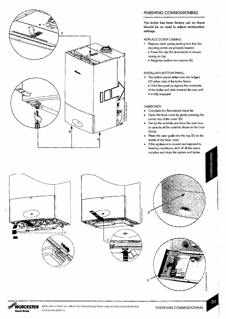
The boiler has been factory set so there should be no need to adjust combustion settings
REPLACE OUTER CASING
Replace outer casing making sure that the
securing points are properly located
Press the clip (A) downwards to secure
casing on top
Retighten bottom two screws (B)
INSTALLING SOnOM PANEL
2 The bottom panel slides onto two ledges
(C) either side of the boiler frame
Hold the panel up against the underside
of the boiler and slide towards the rear until
it is fully engaged
HANOOVER
Complete the Benchmark check list
Open the facia cover by gently pressing the
centre top of the cover (0) Set up the controls and show the user how
to operate all the controls shown in the User
Guide
Place the user guide into the tray (E) on the
inside of the facia cover
If the appliance is unused and exposed to
freezing conditions shut off all the mains
supplies and drain the system and boiler
I I
o
___tIfII
I l
I I J I I I I I
FINISHING COMMISSIONING
E
~ORCESTER INSTALLATION amp SERVICING INSTRUCTIONS FOR WORCESTER BOSCH GREENSTAR 25CovaOCOV37COiI2COi
6720 613 700a(200611)
CAUTION TURN OFF THE GAS SUPPLY AND ISOLATE THE MAINS SUPPLIES BEFORE STARTING ANY WORK AND OBSERVE ALL RELEVANT SAFETY PRECAUTIONS
IMPORTANT AFTER REPLACEMENT OF ANY COMPONENTS ALWAYS CHECK FOR GAS SOUNDNESS WHERE RELEVANT AND CARRY OUT FUNCTIONAL CHECKS AS DESCRIBED IN COMMISSIONING ANY O-RING OR GASKET THAT APPEARS DAMAGED MUST BE REPLACED
-----------shy
shytIgttIgt~u~-~---- 1 ~ 1M ~ ~
I
I =r bullI ~ -J bull
I j~ I_-----1- ~ I
-25- i I J I JO Isa ~ 0 tIgt I
----- ~ 2
~ I 1
I I
I I I
I I I I 1
Irt ~~
_---_
I I I I I ------ I I a I I ~ I I I I
I I I
I I
I I I I ---~ I
L ~ I I L_____~~-J
6720611927-0710 _-_
INSPECTION AND SERVICE
IMPORTANT Any service work must be
carried out by competent registered engishy
neers such as British Gas or Corgi regisshy
tered engineer
bull To ensure the continued efficient operation
of the appliance it must be checked at regumiddot
lar intervals
bull The frequency of servicing will depend upon
the particular installation conditions and
usage However an annual service is recshy
ommended
bull The extent of the service required by the
appliance is determined by the operating
condition of the appliance when tested by
fully qualified engineers
INSPECTION
1 Check that the terminal and the terminal
guard if fitted are clear and undamaged
2 If the appliance is in a compartment or cupshy
board check that the specified service
space around the appliance is clear
3 Check all the joints and connections in the
system and remake any that show signs of
leakage Refill and re-pressurise if applicashy
ble as described in Commissioning
Operate the appliance and take note of
any irregularities Call up the last fault stored
by the Bosch Heatronic Service Function
0 Refer to Fault Finding for rectification
procedures
4 Please consult Operational Procedures
Part 11 Servicing Policy
INSTALLATION amp SERVICING INSTRUCTIONS FOR WORCESTER BOSCH GREENSTAR 25COV3OCO37CDV42 CO AORCESTERINSPECTION AND SERVICE 6720 613700a (200611) Bosch Group
I I
I I
J I
shy
INSPECTION AND SERVICE
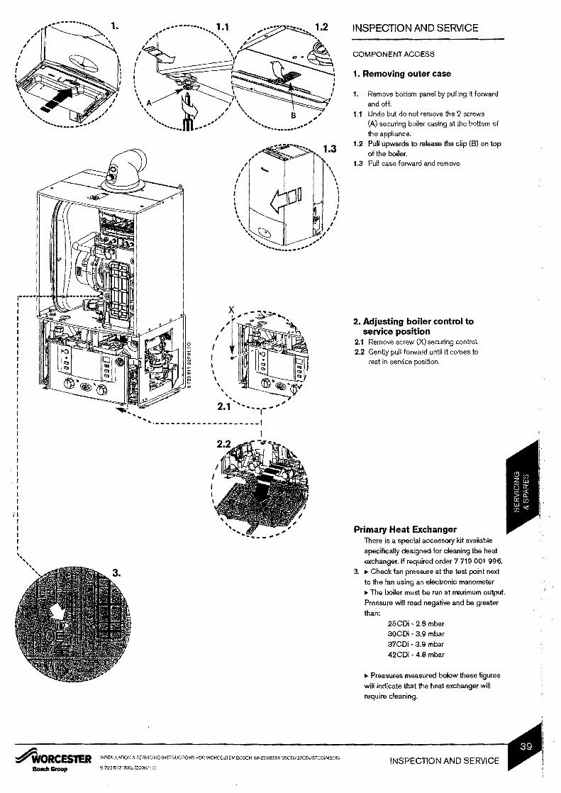
COMPONENT ACCESS
1 Removing outer case
1 Remove bottom panel by pulling it forward and off
11 Undo but do not remove ille 2 screws (A) securing boiler casing at ille bottom of
ille appliance _ -
12 Pull upwards to release the clip (B) on top of the boiler
13 Pull case forward and remove
I
-_ 11
I I I I I I I I
I
I
r I ~ I
II -
----shy I I 2 Adjusting boiler control toI I service position I 21 Remove screw (X) securing control I I 22 Gently pull forward until it comes to I rest in service position I I I I I
It__ 21 - -
I ~~
1 ---- ---- ------- --I1 I I I I I I I I I I I I
II I I Primary Heat Exchanger I I There is a special accessory kit available I specifically clesigned for cleaning the heat
exchanger If required order 7 719001 996
3 Check fan pressure at the test point next
to the fan using an electronic manometer
The boiler must be run at maximum output
Pressure will read negative and be greater
than
25CDi bull 28 mbar
30CDimiddot 39 mbar
37CDi middot39 moor
42CDi 48 moor
Pressures measured below these figures
will indicate that the heat exchanger will
require cleaning
~WORCESTER INSTALLATION amp SERVICING INSTRUCTIONS FOR WORCESTER EIOSCH (lREENSTAR 25CDY3OCDY37CDV42CDi INSPECTION AND SERVICE 672061$ 7OOa(2006111)Bosch Group
I I
I I
INSPECTION AND SERVICE
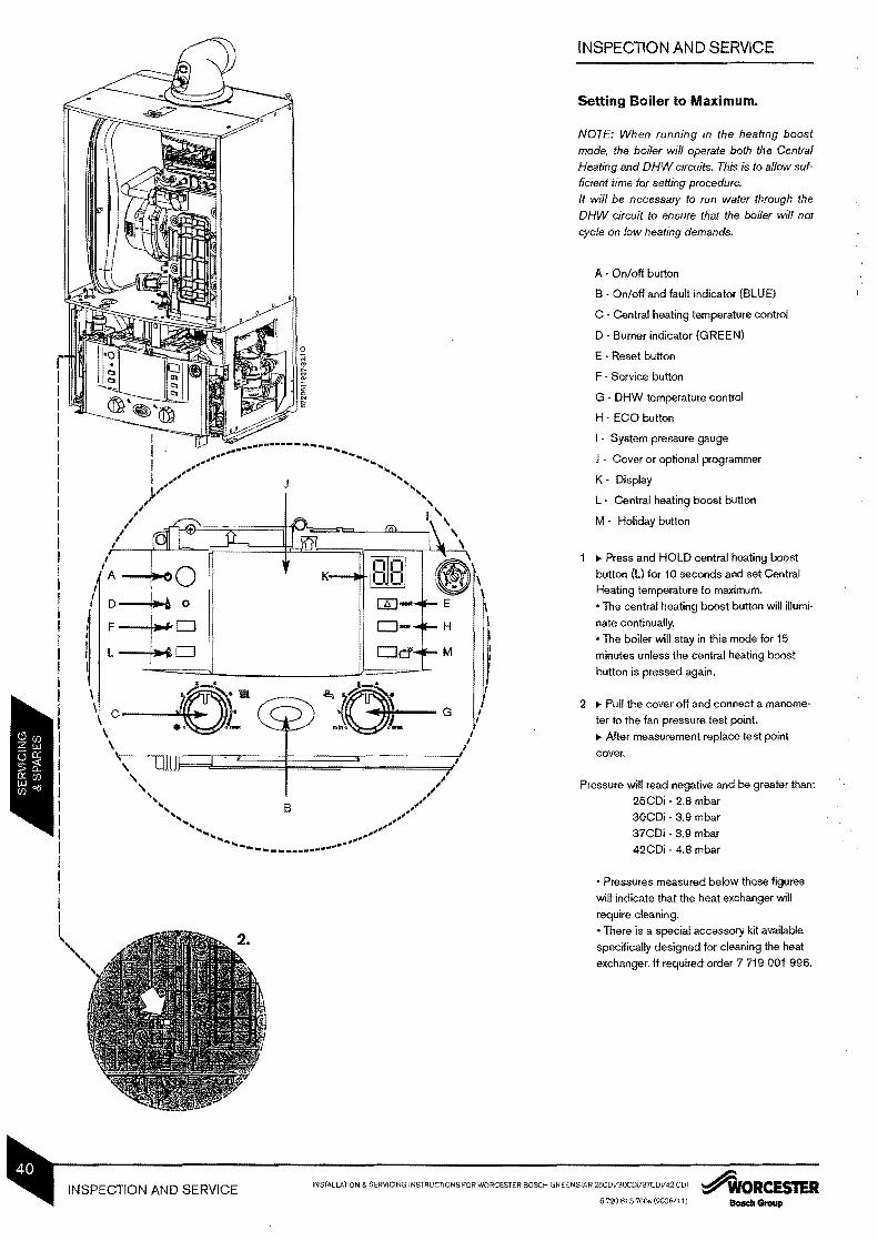
Setting Boiler to Maximum
NOTE When running in the heating boost mode the boiler will operate both the Central Heating and DHW circuits This is to allow sufshyficient time for setting procedure It will be necessary to run water through the DHW circuit to ensure that the boiler will not cycle on low heating demands
A - Onoff button
B - Onoff and fault indicator (BLUE)
C - Central heating temperature control
D - Burner indicator (GREEN)
E - Reset button
F - Service button
G - DHW temperature control
H - ECO button
System pressure gauge
Cover or optional programmer
K - Display
L - Central heating boost button
M - Holiday button
IIgt Press and HOLD central heating boost
button (L) for 10 seconds and set Central
Heating temperature to maximum
I bull The central heating boost button will illumishy
nate continually
bull The boiler will stay in this mode for 15
minutes unless the central heating boost
button is pressed again
2 IIgt Pull the cover off and connect a manomeshy
ter to the fan pressure test point
IIgt After measurement replace test point
cover
Pressure will read negative and be greater than
25CDi - 28 mbar
30CDi - 39 mbar
37CDi - 39 moor
42CDi - 4B mbar
bull Pressures measured below these figures
will indicate that the heat exchanger will
require cleaning
bull There is a special accessory kit available
specifically designed for cleaning the heat
exchanger If required order 7 719 001 996
INSTALLATION amp SERVICING INSTRUCTIONS FOR WORCESTER BOSCH GREENSTAR 25CDil3OCDi37CDV42 COl tAORCESTERINSPECTION AND SERVICE 6720 613 700 (20061 1)
I I I I I
I I I I I I I I I I I I I I I I I I I I I I I I I I I t I I
I I I I I I
I
- III _
I
I I
I
I
1
---
I I I r
I I I D I I
~ I C
~8 II
til ttfI
shy
2~ bull[ 1
I I I
I I I I I I I
I I r I
I I I I r I I I
I I I I
I I I I
I I
INSPECTION AND SERVICE
COMBUSTION TESTING MUST BE CARRIED OUT BY A COMPETENT PERSON IT MUST NOT BE ATTEMPTED UNLESS THE PERSON CARRYING OUT THE COMBUSTION CHECK IS EOUIPPED WITH A COMBUSTION ANALYSER CONFORMING TO BS 7927 AND IS COMPETENT IN Irs USE
To Clean the Heat Exchanger Remove outer case and base panel and
isolate the appliance from power
1 Remove cleaning access cover (8) seal
(C) and metal plate (0) securing it if preshy
sent
21 Loosen any deposits in the heat exchanger
from top to bottom using the cleaning blade
22 Clean the heat exchanger from top to botshy
tom using the brush
Refit the clean out coverplates in reverse
order using a new seal (C) and tighten
screws
~WORCESTER INSTALLATiON amp SERVICING INSTRUCTIONS FOR WORCESTER BOSCH GREENSTAR 25CDil30COil37CQil42COi INSPECTION AND SERVICE 6720 613 QQ (200611)BolIch GrouP
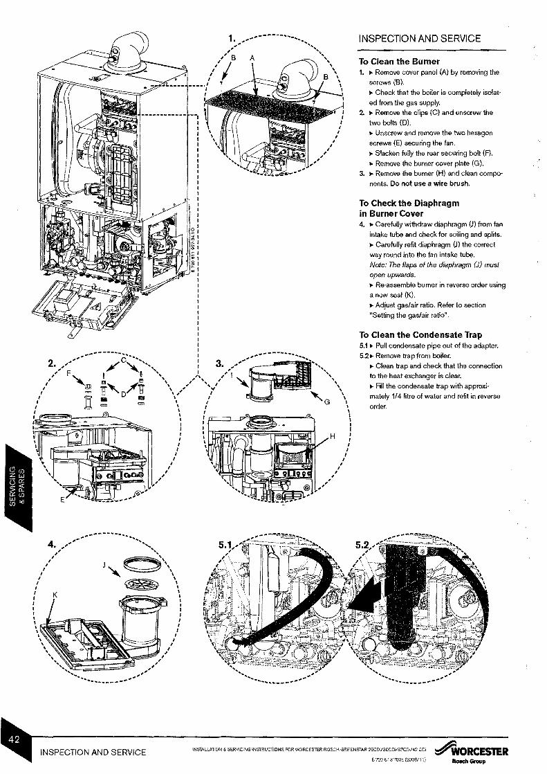
1 --_ INSPECTION AND SERVICE
1
B To Clean the Burner I I
1 Igt Remove cover panel (A) by removing the I ~ screws (B)
I Igt Check that the boiler is completely isolatshy
ed from the gas supply
2 Igt Remove the clips (C) and unscrew the
two bolts (0)_
Igt Unscrew and remove the two hexagon
screws (E) securing the fan
Igt Slacken fully the rear securing bolt (F) Igt Remove the burner cover plate (G)
3 Igt Remove the burner (H) and clean composhy
nents Do not use a wire brush
To Check the Diaphragm in Burner Cover 4 Igt Carefully withdraw diaphragm (J) from fan
intake tube and check for soiling and splits
Igt Carefully refit diaphragm (J) the correct
way round into the fan intake tube
Note The flaps of the diaphragm (1) must
open upwards
Igt Re-assemble burner in reverse order using
a new seal (K)
Igt Adjust gasair ratio Refer to section
Setting the gasair ratio
To Clean the Condensate Trap 51 Igt Pull condensate pipe out of the adapter
521gt Remove trap from boiler
Igt Clean trap and check that the connection
to the heat exchanger is clear
Igt Fill the condensate trap with approxishy
mately 14 litre of water and refit in reverse
I order I I I I I I I I
INSTALLATION amp SERVICfNG INSTRUCTIONS FOR WORCESTER BOSCH GREENSTAR 25CDil3OCOilS7COil42 COi ~ORCESTERINSPECTION AND SERVICE 6720 6 t 3 700 (200IY I 1) BoKhGroup
REPLACEMENT OF PARTSCAUTION TURN OFF THE GAS SUPPLY AND ISOLATE THE MAINS SUPPLIES BEFORE STARTING ANY WORK AND OBSERVE ALL RELEVANT SAFETY PRECAUTIONS
I
1iIIo 11
Y
ttl - -shy
13
I I I I I I I I I I I I I I I I I I I I I I I I I I I I I I I
I
L
IMPORTANT AFTER REPLACEMENT OF ANY COMPONENTS ALWAYS CHECK FOR GAS SOUNDNESS WHERE RELEVANT AND CARRY OUT FUNCTIONAL CHECKS
AS DESCRIBED IN COMMISSIONING ANY O-RING OR GASKET THAT APPEARS DAMAGED MUST BE REPLACED
1 Removing outer case 1 Igt Remove bottom panel by pulling it forward
and off 11 Igt Loosen but do not remove the 2 screws
(A) securing boiler casing at the bottom of the appliance
121gt Pull upwards to release the clip (B) on top of the boiler
13 Igt Pull case forward and remove
2 Moving boiler control to service position
21 Igt Remove screw (X)securing control 221gt Gently pull forward
3 Primary sensor Igt Press retaining clip on plastic moulding
and pull upwards until clear of pocket in
heat exchanger
Igt Separate sensor from connector coat
new sensor with heat conductive paste and
replace
4 Overheat thermostat Igt Remove two electrical connectors from
621gt Undo the union connection (E) at the botmiddot
tom of the expansion vessel
Igt Remove expansion vessel from boiler
Igt Set the pressure of the new vessel to that
required by the system
I
Jbullbull I I I I I I I I I
I I
I
I I
I
I I
I I
I I
I I I I I
lt -1 0 61
~
INSTALLATION amp SERVICING INSTRUCTlONS FOR WORCESTER BOSCH GREEIltSTAR 25CDV3OCDV37CDif42CDi~ORCESTER INSPECTION AND SERVICE 6 m 613 700 (200611)BolIch Group
REPLACEMENT OF PARTS
I I I I I I I I I I I I I I I I I I I I I I I I I I I
fI
I
A_~Hl I I I I I
7 Gasvalve Igt Isolate gas supply at boiler gas cock
Igt Push air inlet tube (A) upwards
71 Igt Undo top gas connection (B) to gas valve
71 Igt Undo bottom gas connection (C) to gas
valve
72 Igt Undo two securing screws (D) on the
underside of casing
Igt Pull valve up and forward out of boiler
Igt Disconnect electrical connections
Igt Replace valve with new seals and check
for gas soundness
Note The valve wiJJ require setting follow proshycedure middotSetting the gasair ratio in the gas
conversion section
8 Siphon 81 Igt Pull condensate pipe out of the adapter
821gt Remove trap from boiler
Igt Clean trap and check that the connection
to the heat exchanger is clear
Igt Fill the condensate trap with approxishy
mately 14 litre of water and refit in reverse
order
INSTALLATION amp SERVICING INSTRUCTiONS FOR WORCESTER BOSCH GREEN~rri~ )3OCOltl37CDi42 CD ~ORCESTERREPLACEMENT OF PARTS 6J20 613 7003 (200611
PCBfuse Remove fuse (B) from the PCB and
replace
There is a spare fuse clipped into the
cover
Transformer I PCB Disconnect all electrical connections
from the control
Remove 5 screws (C) retaining the
rear panel of the control and remove
panel
~- - - 9 REPLACEMENT OF PARTS
1 I
I 9 Access to boiler control I I componentsI
rmiddotmiddotmiddotmiddot----middotmiddot--middotmiddotmiddotmiddot-middotmiddotmiddot--middotmiddot------middot-middot-~ f Remove 3 screws (A) and remove cover from control I
I
I
10 I
r gt (I ( I ~~I - __-
I I( I I I I I 11 I I I I 1I
I I I _-
I I I I I I I I I I I I I I I
I
I
I
I
-- - -
_ _ _-_ - -
- I
~WORCESTER INSTALLATION amp SERVICING INSTRUCTIONS FOR WORcESTER BOSCH GREENSTAR 25CDiI30CDiI37CDV42CDi REPLACEMENT OF PARTS 6 720 613 7()()a (2000111)
REPLACEMENT OF PARTS
IMPORTANT AFTER REASSEMBLY THE COMBUSTION MUST BE CHECKED USING THE PROCEshyDURE IN THE SECTION SETTING THE GAS AIR RATIO MEASUREshyMENT AND SETTING (IF NECESshySARY) OF THE GAS RATIO MUST NOT BE ATTEMPTED UNLESS THE
Imiddotmiddotmiddotmiddotmiddotmiddot PERSON IS EQLlIPPED WITH AI
I COMBUSTION ANALYSER CONshyI FORMING TO BS 7927 AND IS COMshyI I PETENT IN ITS USE I I I I I 12 Fan assembly I ~ Remove electrical connector from fan I
~ Remove condensate trap I I (see page 42) I 121 ~ Undo the union connection (A) I I ~ Remove wire clip (8) from airgas I adjustment assembly (e) then pull gas I
pipe down I I 122 ~ Unscrew two screws (D) I 123 ~ Remove fan from boiler I
124 ~ Remove three screws retaining the I I airgas adjustment assembly (E) I ~ Reassemble with new fan assuring that I I seals are correctly fitted I
I I I I I I I E bullbullbullbullbullbullbullbull J I I I I I bull I I
~ ~-
lNSTALLATION amp SERVlCING INSTRUCTIONS FOR WORCESTER BOSCH GREENSTAR 25CDi3OCDV37CO2 COl AORCESTERREPLACEMENT OF PARTS 67ru 613700 (=611) BoIscIt Group
I I I I I I I I I I
-
I I
I I
f I I
I
I f I I
I I
I I
I
REPLACEMENT OF PARTS
14 Airgas manifold 141 Remove cover panel (Al by removing
the screws (B) Check that the boiler is completely isoshylated from the gas supply
142 Remove the clips (e) and unscrew the two bolts (D) Unscrew and remove the two hexagon screws (E) securing the fan Slacken fully the rear securing bolt (F)
143 Remove airgas manifold (I) 144 Open airgas manifold (I)
Carefully withdraw diaphragm (J) from fan intake tube and check for soiling and splits
15 Burner Remove the bumer (H) Replace new burner in correct posishytion Ensure that a new seal (K) is used
-fIJ
15 -
I I
I I
I
f I
f I I I
I I
I I
I I
~ORCES1ER INSTAlLATION amp SERVICING INSTRUCTIONS FOR WORCESTER BOSCH GREENSTAR 25COil3OCDV37CDV42CDi REPLACEMENT OF PARTS 6720613700 (2008111)
REPLACEMENT OF PARTS
16 Heat exchanger ~ Isolate flow and return valves and drain
the boiler
~ Remove condensate trap
(see page 42)
~ Remove fan assembly (see page 46)
161 ~ Remove plastic nut (A) from the base
of the inner casing
162 ~ Remove return pipe at the bottom of heat exchanger
163 ~ Remove screw at the top of the heat
exchanger (e) ~ Unscrew the flow pipe (D)
164 ~ Undo flue connection (E) from
sump (F)
~ Pull flue pipe up
~ Remove the heat exchanger
INSTALLATION amp SERVICING INSTRUCTIONS FOR WORCESTER BOSCH GREENSTAR 25COltl3OCDif37CDltl42 CD AORCESTERREPLACEMENT OF PARTS 6720 53 700a (200611)
--
I I I I
REPLACEMENT OF PARTS
17 Diverter valve motor There is no need to drain the appliance
Disconnect the electrical connector
from the diverter valve motor
171 Pull the motor assembly (A) towards
you The assembly will slide free from the
valve bull
To refit follow the above in reverse
Note In case of problems when refitting
the motor Connect the electrical conmiddot
nectar to the motor and switch the applishy
ance on Then the motor goes to the
middle position andyou can refit it withshy
out difficulty
18 Diverter valve Ensure the appliance has been fully
drained Disconnect the electrical connector
from the diverter valve motor
Undo the two screws holding the valve
to the plastic housing
181 Withdraw the valve (B) and clean the
valve chamber if necessary
To refit follow the above in reverse
Ensure any seals that have been disshy
turbed are renewed
bull 19 Auto air vent I I Ensure the appliance has been fully
I drained
Use a screwdriver or similar to rotate t
1-bull- bull-
191 iI~
C ---- -
- 192 191
the air vent anticlockwise -- -X-
~ 192 Lift the air vent (e) out of the housing
I I and remove I I
I To refit follow the above in reverse I
I
I I
20 DHW temperature sensor i Ensure the domestic hot water circuit I is fully drained
Disconnect the electrical connection
from the sensor degf
ii Withdraw the spring clip Withdraw the sensor (0) from the
housing
To refit follow the above in reverse
- - 201-~55 ~ gtshye~ _
Ibullbullbullbullbullbullbullbull I
o
~RCESTER INSTALLATlONamp SERVIC1NG INSTRUCTIONS fOR WORCESTER BOSCH GREENSTAR 25COil3OCDil37CDil42CDi REPLACEMENT OF PARTS 6720 613 700 (200611)
0
REPLACEMENT OF PARTS
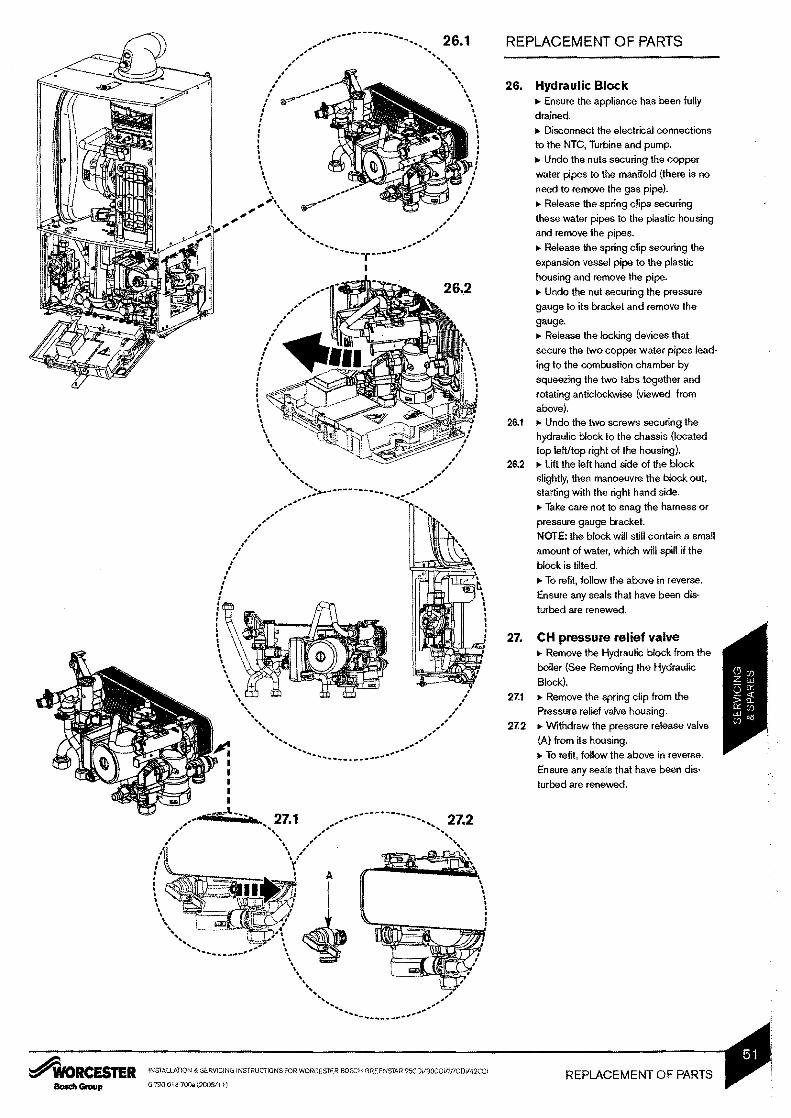
23~-
I I
I
I
I I I I
110110shy
INSTALIATION amp SERVICING INSTRUCTIONS FOR WORCESTER BOSCH GREENSTAR 25CDV3OCO37Coil42 co
REPLACEMENT OF PARTS
21 Pump head Ensure the appliance has been fully
drained
211 Disconnect the electrical connections
from the pump following steps 1 to 4
212 Remove the four Allen bolts (A) securshy
ing the pump at each corner
213 Gently pull the pump towards you and
remove
To refit follow the above in reverse
22 Pressure gauge Ensure the appliance has been fully
drained
Withdraw the spring clip from the presshy
sure sensing head housing
Undo the nut on the rear of the presshy
sure gauge
Remove the pressure sensing head
and pressure gauge capillary from the
housing
To refit follow the above in reverse
DO NOT omit the washer from the capilshy
lary when fitting a replacement gauge
23 Flow sensor flow restrictor housing and filter Ensure the domestic hot water circuit
is fully drained
Disconnect the electrical connection to
the turbine
Remove the spring clip from the housshy
ing and move the brass pipe to one side
231 Withdraw the flow sensor and filter
from the housing
Using the cartridge tag withdraw the
flow restrictor housing If the regulator
housing has become stuck a pair of long
nosed pliers may be used to grip the
housing
To refit follow the above in reverse
Ensure any seals that have been disshy
turbed are renewed
24 Flow regulator Remove the flow restrictor housing
(See Removing the flow sensor flow
regulator and filter)
241 Using a small Allen key or similar push
the flow restrictor cartridge out of its
housing
To refit follow the above in reverse
Ensure any seals that have been disshy
turbed are renewed
25 Drain tap Ensure the appliance has been fully
drained
251 Rotate the drain tap fully anticlockwise
252 Withdraw the drain tap from its housing
To refit follow the above in reverse
Ensure any seals that have been disshy
turbed are renewed
AORCESTER 6 20 613 7QOa (2006111)
bull bull
-- -- 26 1 REPLACEMENT OF PARTS
~
26 Hydraulic Block I
II
Ensure the appliance has been fully I bull drained
bull bull I
I Disconnect the electrical connections bull t Ibull Ibull
bull bull bull I I
I I I
A I I
-r middot--
I
262
262
IbullbullI
I I 261bull
27
271
272
to the NTC Turbine and pump
Undo the nuts securing the copper
water pipes to the manifold (there is no
need to remove the gas pipe)
Release the spring clips securing
these water pipes to the plastic housing
and remove the pipes
Release the spring clip securing the
expansion vessel pipe to the plastic
housing and remove the pipe
Undo the nut securing the pressure
gauge to its bracket and remove the
gauge
Release the locking devices that
secure the two copper water pipes leadshy
ing to the combustion chamber by
squeezing the two tabs together and
rotating anticlockwise (viewed from
above) Undo the two screws securing the
hydraulic block to the chassis (located
top lefttop right of the housing) Lift the left hand side of the block slightly then manoeuvre the block out
starting with the right hand side
Take care not to snag the harness or
pressure gauge bracket
NOTE the block will still contain a small
amount of water which will spill if the
block is tilted
To refit follow the above in reverse
Ensure any seals that have been disshy
turbed are renewed
CH pressure relief valve Remove the Hydraulic block from the
boiler (See Removing the Hydraulic
Block)
Remove the spring clip from the
Pressure relief valve housing
Withdraw the pressure release valve
(A) from its housing
To refit follow the above in reverse
Ensure any seals that have been dismiddot
turbed are renewed
bulldI
I bullbullbullIbullI
~~
I
I I
I I
IbullI I I I Ibull
shy
_---_ -shy
271 ---- 27 2
A
-
I I I I
~RCESTER INSTALLATION amp SERVICING INSTRucrlONS FOR WORCESTER BOSCH GREENSTAR 25CDil30COil37CDil42CDi REPLACEMENT OF PARTS 6720613700(200611)
REPLACEM ENT OF PARTS
-------shy
28 Plastic protection device Igt Ensure the system is fully drained
Igt Disconnect all pipes connected to the
pump housing
Igt Remove the electrical connection to
the pump
Igt Withdraw the metal clip to the right of
the pump head to release the pump
housing
Igt Slide the device to the left and then
withdraw it from the appliance
281 Igt Remove the spring clip from the presshy
sure relief valve housing
282 Igt Withdraw the pressure relief valve (Al Igt To refit follow the above in reverse
Ensure any seals that have been disshy
turbed are renewed
29 DHW Heat exchanger Igt Remove the Hydraulic block from the
boiler (See Removing the Hydraulic
Block)
291 Igt Undo the two screws (B) securing the
plastic housings to the heat exchanger
292 Igt Remove the heat exchanger
Igt To refit follow the above in reverse
Ensure any seals that have been dismiddot
turbed are renewed
INSTALLATION SERVICING STRUCTIONS FOR WORCESTER BOSCH GREENSTmiddotmiddotr V3OCDV37CDil42 CD ~WORCESTERREPLACEMENT OF PARTS 6 720 61 a700 (2006111) Bosch Group
THE SETTING OF THE GAS RATIO MUST BE CARRIED OUT BY A COMPETENT PERSON
SETTING OF THE GAS RATIO MUST NOT BE ATTEMPTED UNLESS THE PERSON CARRYING OUT
THE CONVERSION IS EOUIPPED WITH A COMBUSTION ANALYSER CONFORMING TO BS 7927 AND IS COMPETENT IN ITS USE
----------_
I I
-shyhll I
Ibullr--- I
5 2
I I I
f I
-_1
I
I I
I I f f I I I I I
SETTING THE GASAIR RATIO
5 Setting the CO2 Note When running in the central heating
boost mode the boiler will operate both the
central heating amp DHW circuits This is to allow
sufficient time for the setting procedure It will
be necessary to run water through the DHW
circuit to ensure that the boiler will not cycle on
low heating demands
51 ~ Connect manometer to inlet pressure
point on the gas valve
~ To adjust the CO2 it will be necessary to
first operate the boiler at maximum output
~ Press and hold down the central heating
boost button (A) for 10 seconds until iIIumimiddot
nated
52~ Turn central heating control to maximum
the boiler will then go to maximum output
Note The control will resume normal operamiddot
tion after 15 minutes or if the central heating
boost button is pressed for over a second
53~ Using a flat blade screwdriver set the
C02 via adjuster (8) using table below
Note C02 should be measured 10 minutes
after firing the appliance
Gas type JCO2 setting JC~~ setting maximum minimum
Greenstar 25CDi and 30CDi
Natural gas I 96 plusmnO2 I 90 plusmnO2
LPG I 115 plusmnO2 I 105 plusmnO2
Greenstar 37CDi and 42CDi
Natural gas I 97 plusmnO2 I 91 plusmnO2
LPG J 115 plusmnO2 j 105 plusmnO2
~ Check CO is less than 200 ppm
~ Measure the inlet pressure it should be a
minimum of 18 mbar for natural gas and
37 mbar for LPG
54~ Set the central heating control to minimiddot
mum This will make the boiler go to minimiddot
mum power
55~ Measure the CO2 it should now be at
figure for minimum output If not adjust (C)
on the gas valve until correct
~ Return to maximum and remiddotcheck the
CO2 If correct press and hold down the
central heating boost button for 2 seconds
the button will cease to be illuminated and
the blue power indicator will be permanently
illuminated
~ Remove manometer and re-seal inlet presmiddot
sure point on gas valve
~ Fit new plastic sealing cover on to outlet
adjuster (8)
~ Fit white cover over valve adjuster (C) and
secure with black security tag ~ Remove red arrow from data plate and fit
new one in correct position for gas type
~ Remiddotassemble and refit boiler case
~ Remiddotconnect mains electrical supply and
check boiler operation as stated in the commiddot
missioning section ~ Fit new label from kit over existing label on
7 Electrodes WHS Part No 8718 1070890 GC No H22458
8 Row reg Type E 91itre orange WHS Part No 8716141 1430 GCNo 324823
9 Row reg Type E 11 litre brown WHS PartNo 8716107 044 0
10 11 12 GC No H22460
10 Row reg Type E 131itre olive WHS PartNo 8716 107 045 0 GCNo H31958
11 Row reg Type E 15litre light green WHS PartNo 87161058690 GCNo H31 959
12 Pressure relief valve DHW WHS Part No B 717 401 029 0 GCNo H0252614 15
14
15
Pump assembly WHS PartNo 8716106 3540 GCNo H22463
Pressure gauge WHS Part No B 717 20B 107 0 GCNo H02528
Flow sensor WHSPart No B 716 107 223 0 GCNo H02529
16 17 16 DHW temperature sensor
WHS Part No 8 714 500 OB1 0 GCNo H02538
18 Heat exchanger WHS Part No B 716 108 212 0 GCNo H22465
18 Diverter valve assembly WHS Part No B 716 1068450 GC No H02533
2119 20 19 Diverter valve motor WHS Part No 8716106 B47 0 GCNo H02534
20 Control sensor - primary WHS Part No B 714 500 087 0 GCNo E74536
21 Service booklet Part No 6720612361 0 GC No TO BE CONFIRMEO
INSTALLATQN amp SERVICING INSTRUCTIONS FOR WORCESTER BOSCH GREENSTAR 25CDV3OCDi137CDil42 CDi ~ORCESTERSHORT PARTS LIST 6 720 613 700 (200611)
~~ 11 I ~ gt --~
~ I
I Ir---------- t
x shy
f f
I I I I
-_ E
~- -shy shy -
LPG CONVERSION
ISOLATE MAINS ELECTRICAL SUPPLY AND REMOVE OUTER CASE AS SHOWN IN THE INSTALLATION COMMISSIONING amp SERVICING INSTRUCTIONS
THE CONVERSION MUST BE CARRIED OUT
BY A COMPETENT PERSON IT MUST NOT
BE ATTEMPTED UNLESS THE PERSON CARRYING OUT THE CONVERSION IS
EOUIPPED WTH A COMBUSTION ANALYSER
CONFORMING TO BS 7927 AND IS
COMPETENT IN ITS USE
Important The appliance shall not be installed into a room or internal space below ground level when it is intended for use with LPG (propane - G31) This does not preclude the installation into a room or space which is a basement on one side of the building but open to ground on the opposite side
Installation Regulations In addition to those specified in the main booklet the following standard applies when converting to an LPG appliance BS 5842 Domestic Propane Gas Burning Installations
All conversions will require the air gas ratio to be set (orrectly for the gas used The proltedure for setting the air gas ratio is at the rear of these instructions
1 Moving boiler control to service position Igt Remove boiler case as described on
page 39
111gt Remove screw (X) from retaining bracket 121gt Lower control panel into service position
NOTE This fault finding information is for guidance only Worcester Bosch cannot be held responsible for costs incurred by persons not deemed to be competent
The electronic control system for this boiler incorporates a blue central indicator This normally confirms the permanent mains supply but by flashing durshy
ing a fault provides a guide to the cause as listed
This fault finding system assumes that the appliance has been operating normally until the time of failure (ie not a first installation error)
PRELIMINARY CHECKS Preliminary electrical system checks are the first electrical checks to be carried out during a fault-finding procedure
On completion of the ServiceFault-Finding task which has required the breaking and remaking of electrical connections check
(a) EARTH CONTINUITY (b) SHORT CIRCUIT CHECK (c) POLARITY and (d) RESISTANCE TO EARTH
An optional text display is avaliable which gives a text description of the service functions of the boiler
A7 Hot water NTC sensor defective Check hot water NTC sensor and connecting lead for
circuit breaksshort circuits
AS Break in communication to TD200 orand RnO Check electrical connections
bl Code plug not detected Insert code plug correctly test and replace if necessary
C6 Fan speed too low Check fan lead and connector and fan replace as
necessary
E2 CH flow NTC sensor defective Check CH flow NTC sensor and connecting lead
E9
EA
FO
F7
Safety temp limiter in CH flow has tripped
Rame not detected
Internal error
Rame detected even though appliance switched off
Check system pressure check safety temp limiters
check pump operation check fuse on pcb bleed applishy
ance
Is gas cock turned on Check gas supply pressure
power supply igniter electrode and lead ionisation
sensing electrode and lead flue duct and C02 level
Check electrical connector contacts programmer intershyface module ignition leads are not loose replace pcb if
necessary
Check electrode assembly dry pcb Rue clear
FA Rame detected after gas shut off Check gas valve and wiring to gas valve Clean condenshy
sation trap and check electrode assembly Flue clear
Fd Reset button pressed by mistake Press reset button again
More detailed fault finding procedures are described in the Service booklet for the Engineer number 6 720 612 361
INSTALLATION amp SERVICING INSTRUCTIONS FOR WORCESTER BOSCH (lREENSTAR 25CDv3OCDil37CDi42 CD ~WORCESTERFAULT FINDING 6 720 61 B 700 (200611)
II [~
z ~ ~ ~ w C1 5 a Z
13
~ ~ - ~ ~ u
~ tii o ~ g l ~ ~ r Ggt
ri z ~ ~
~ ~ 5 2 1-1 9
o m Z j raquo r I m j Z G)
C Z
~ B z
POWER BLUE SWITCH f LIGHT r-shy
ON ON
Room thermostat andor
mains programmer ON (or link fitted at
Sfl0) AND t--shy
Facia mounted programmer (if
fitted) ON AND
CH control knob ON
3 minute wait
Fan toCENTRAL
HEATING startrJI DEMAND
Diverter valve in CH position
Pump ON
f--Joshyspeed
Gas valve OFF Fan overrun 30 seconds
Over temperature shut-down if water temperature is 6degC
above set value
I
IGNITION SEQUENCE ~ (see detail)
I
GREEN FLAME 1--shyLIGHT
ON
10 second stabilisation ~
period
IGNITION SEQUENCE
YESSpark BURNERignition -
LIT4 seconds
t r n
LOCKOUT -------- YES
NO
5th attempt
NO
Stop spark Wait
10 seconds
set temperature (36~88degC)
Fan (amp gas) modulation to achieve
i--JshyEND OF BOILER
DEMAND
Gas valve OFF
Pump run 3 minutes
Fan run 30 seconds
o m ~ ~ r r m ~ z Ggt
c z Q 6 z
---
C
Burner shut down If primary temperature
95C i-IIf Diverter valve opens
toCH
Over temperature Wait shut-down If waterGas valve OFFr- shy 5 seconds temperature is 10middotC r
above set value
DOMESTIC HOTTap open WATER
(recognised DEMAND Fan (amp gas) modulation to achieve
set temperature (4Q-eOdegC)
GREEN FLAME LIGHT
ON
Fan (amp gas)IGNITION SEQUENCE ~
YES BURNER r-------shyLIT
NO
Stop spark Wait
10 seconds
0 0 m r m ~ raquo z o o r ~ -n
Z Q o z
z j
~ ~
~ Z l 9 ~ () ~ () rn l rn
~ I GO 0
gj Z
j
OJ ~ g ~ 92 R 0
~ ~ ~ ~ 0gt ~ ~
I~ I
POWER SWITCH i-J
ON
BLUE LIGHT
ON
~
by flow turbine)
ECO button not
Illuminated bull (ie preheat requested)
AND 20 minutes
since last preshyheat demand
AND temperature at least 100 below set
point
Set by pressing ECO button If proshygrammerls fitted this is
set by a comshybination of
programmer (DHW)
demand and ECO button
(priority over all other
demands)
PREHEATf-Joo DEMAND
-
Diverter valve inDHW position
Pump ON
I-- shy
f-
-----YES LOCKOUT
IGNITIONFan to SE~UENCE r+start ~ (see detail)speed
---JIooshy4 seconds
NO
5th attempt
modulation to achieve (4Q-aOdegC)
DEMAND END
~ Gas valve
OFF Pump run 3
minutes Fan run 30
seconds
ENDrD~ ~
Gas valve OFF
Stop pump Stop fan
1J u m I m ~ raquo z C1 C1 I
~ c z ~ o z
PROTECTION FUNCTION
Boiler temperature below8C
Pumpantiseize
-------_
Run autofroststat function
HPump run 5 seconds I every 24hrs
DHW demand active
Holiday mode set to ON Frost protection active
All other demands not active
~RCES1ER INSTALLATIONlaquo SERVICING INSTRUCTIONS FOR WORCESTER 80SCH GREENSTAR 2SCDil3OCOV37COV42COi PROTECTION FUNCTION 6720 613 700 (200611)
INSTRUCTION MANUAL INSTALLATION COM MISSION I NG
ampSERVICING
EXCELLENCE COMES AS STANDARD Worcester Bosch Group
Cotswold Way Wamdon Worcester WR4 9SW
Tel 01905 754624 Fax 01905 754619
Worcester Bosch Group is a trading name of
BBT Thermotechnology UK ltd
wwwworcester-boschcouk
CONTACT INFORMATION INSTALLATION ampSERVICING INSTRUCTIONS
WORCESTER BOSCH
TECHNICAL 08705 266241
SERVICE 08457 256206 SPARES 01905 752571
LITERATURE 01905 752556
TRAINING 01905752526
SALES 01905 752640
WEBSITE wwwworcester-boschcouk
WATER TREATMENT
FERNOX 01799550811
wwwfernoxcom
SENTINEL 0151 4209595
wwwbetzdearbomcomsentinel
FLUE TERMINAL GUARD
TOWER FLUE COMPONENTS
VALE RISE
TONBRIDGE
TN91TB
STORE THE APPLIANCE IN A DRY AREA
PRIOR TO INSTALLATION
LIFTING AND CARRYING PRECAUTIONS
bull Lift only a manageable weight or ask for
help bull When lifting the boiler bend the knees
and keep the back straight and feet apart
bull Do not lift and twist at the same time
bull Lift and carry the boiler close to the body
bull Wear protective clothing and gloves to protect from any sharp edges
PLEASE READ THESE INSTRUCTIONS CAREFULLY BEFORE STARTING INSTALLATION
THESE INSTRUCTIONS ARE APPLICABLE TO THE WORCESTER BOSCH APPLIANCE MODEL(S) STATED ON THE FRONT COVER OF THIS MANUAL ONLY AND MUST NOT BE
USED WITH ANY OTHER MAKE OR MODEL OF APPLIANCE
THE INSTRUCTIONS APPLY IN THE UK ONLY AND MUST BE FOLLOWED EXCEPT FOR ANY
STATUTORY OBLIGATION
THIS APPLIANCE MUST BE INSTALLED BY A COMPETENT PERSON FAILURE TO INSTALL
CORRECTLY COULD LEAD TO PROSECUTION
IF YOU ARE IN ANY DOUBT CONTACT WORCESTER BOSCH TECHNICAL HELPLINE
DISTANCE LEARNING AND TRAINING COURSES ARE AVAILABLE FROM WORCESTER
BOSCH
PLEASE LEAVE THESE INSTRUCTIONS THE USER GUIDE AND THE COMPLETED BENCHMARK LOG BOOK OR A CERTIFICATE CONFIRMING COMPLIANCE WITH IS 813 (EIRE ONLy) WITH THE USER OR AT THE GAS METER AFTER INSTALLATION OR SERVICshy
ING
ABBREVIATIONS USED IN THIS MANUAL
o Diameter NG Natural Gas
LPG Liquid Petroleum Gas CH Central Heating
DHW Domestic Hot Water
IP Ingress Protection
SEDBUK Seasonal Efficiency of Domestic Boilers in the United Kingdom
SYMBOLS USED IN THIS MANUAL
TIme clock C H only Domestic hot water
Central heating Programmertimer
Cold water main supply Room thermostat
Electricity supply Wait time period
Gas supply
INSTAlLATION amp SERVICIgtG INSTRUCTIONS FOR WORCESTIER BOSCH GREEN STAR 2SCDvaOCDil37CDV42 CDi ~ORCESTERINSTALLATION amp 6 120 61 a700 (200611) Bolch GrowgtSERVICING INSTRUCTIONS
CONTENTS
SAFETY amp REGULATIONS
SAFETY PRECAUTIONS 4
INSTALLATION REGULATIONS 4
APPLIANCE I N FORMATION
GENERAL INFORMATION 5
TECHNICAL DATA 6
LAYOUT amp COMPONENTS 7-8
PRE-INSTALLATION
CLEANING PRIMARY SYSTEMS 9
MAINS SUPPLIES 10
WATER SYSTEMS amp PIPEWORK 11
CONDENSATE PIPEWORK 12
BOILER LOCATION amp CLEARANCES 13-14
PLUMBING MANIFOLD 15
FLUE TERMINAL POSITIONS 16
FLUE OPTIONS 17-20
INSTALLATION
UNPACKI NG WALL FRAME AND ANCILLARY ITEMS 21
WALL MOUNTING PLATE FLUE OPENING 22
CHARGING LINK (FILLING LOOP) 23
UNPACKING THE APPLIANCE 24
FIniNG THE APPLIANCE BOILER CONNECTIONS 25
FLUE INSTALLATION 26-28
CONDENSATE CONNECTION 29
ELECTRICAL 30
POSITION OF WIRED COMPONENTS 31
COMMISSIONING
PRE-COMMISSIONING CHECKS 32
FILLING THE SYSTEM 33
STARTING THE APPLIANCE 34
WATER TREATMENT 35
COMMISSIONING 36
FINISHING COMMISSIONING 37
SERVICING amp SPARES
INSPECTION AND SERVICE 38-42
REPLACEMENT OF PARTS 43-52
SEHING THE GASAIR RATIO 53
SHORT PARTS LIST 54
CONVERSION KITS
LPG CONVERSION 55
FAULT FINDING amp DIAGNOSIS
FAULT FINDING 56
CENTRAL HEATING FUNCTION 57
PREHEAT AND DHW FUNCTION 58
PROTECTION FUNCTION 59
INSTALLATION amp SERVICII IIltSTRUCTIONS FOR WORCESTER BOSCH GREENSTAR 25CDil30CDil37CDV42CDi~ORCESTER CONTENTS 6720 613 700 (200611)Bosch Group
SAFETY PRECAUTIONS INSTALLATION REGULATIONS
IF YOU SMELL GAS
x DONT SMOKE OR STRIKE MATCHES
X DONT TURN ELECTRICAL SWITCHES ON OR OFF
V DO PUT OUT NAKED FLAMES
V DO OPEN DOORS AND WINDOWS
V DO KEEP PEOPLE AWAY FROM THE AREA AFFECTED
V DO TURN OFF THE CONTROL VALVE AT THE METER
V TELEPHONE THE NATIONAL GAS EMERGENCY SERVICE ON 0800111999
(IendmorlO A Benchmark Log Book is provided by the manufacturer for the installer to complete
including their CORGI registration number to confirm that the boiler has been installed
commissioned and serviced according to the manufacturers instructions
IMPORTANT The completed Benchmark Checklist will be required in the event of any
warranty work and may be reqUired by the local Building Control Inspector
HEALTH amp SAFETY The appliance contains no asbestos and no substances have been used in the
construction process that contravene the COSHH Regulations (Control of Substances
Hazardous to Health Regulations 1988)
COMBUSTIBLE AND CORROSIVE MATERIALS Do not store or use any combustible materials (paper thinners paints etc) inside or
within the vicinity of the appliance
Chemically aggressive substances such as halogenated hydrocarbons containing
chlorine or fluorine compounds can corrode the appliance and invalidate any warranty
FITTING amp MODIFICATIONS Fitting the appliance and any controls to the appliance may only be carried out by a
competent engineer in accordance with the Gas Safety (Installation and Use)
Regulations 1998
Flue systems must not be modified in any way other than as described in the fitting
instructions Any misuse or unauthorised modifications to the appliance flue or
associated components and systems could invalidate the warranty The manufacturer
accepts no liability arising from any such actions excluding statutory rights
SERVICING Advise the user to have the system serviced annually by a competent qualified
engineer (such as British Gas or CORGI registered personnel) using approved spares
to help maintain the economy safety and reliability of the appliance
IMPORTANT laquo The service engineer must complete the Service Record in the
Benchmark section after each service
Gas Safety (Installation amp Use) Regulations
All gas appliances must be installed by a
competent person in accordance with the above
regulations Failure to install appliances correctly
could lead to prosecution
The appliance must be installed in accordance
with and comply to the curren Gas Safety
Regulations lEE Regulations Building
Regulations Building Standards Scotland
(Consolidation) Building Regulations (Northern
Ireland) local water by-laws Health amp Safety
Document 635 (The Electricity at Work
Regulations 1989) and any other local
requirements
British Standards
The relevant British Standards should be followed
including
BS70741 Code of practice for domestic and hot
water supply
BS6891 Installation of low pressure gas
pipework up to 28mm R1
BS5546 Installation of gas hot water supplies for
domestic purposes
EN 12828 Central heating for domestic premises
BS54401 Rues and ventilation for gas applishy
ances of rated heating not exceeding 70kW (net)
Rues
BS54402 Rues and ventilation for gas applishy
ances of rated heating not exceeding 70kW net
Air Supply
BS7593 Treatment of water in domestic hot
water central heating systems
BS 6798 Installation of gas lired boilers of rated
input up to 70kW net
Where no specific instruction is given reference
should be made to the relevant British Standard
codes of Practice
LPG_ Installation
An appliance using LPG must not be installed in
a room or internal space below ground level unless
one side of the building is open to the ground
limber framed buildings
Where the boiler is to be litted to a timber framed
~WORCESTER INSTALLATION amp SERVICING INSTRUCTIONS FOR WORCESTER BOSCH GREENSTAR 25CovaOCOil37CDV42CDi GENERAL INFORMATION 6720 613 7000 (200611)BolIch Group
TECHNICAL DATA
NATURAL GAS LPG
DESCRIPTION UNITS 25CDi 30CDi 37CDi 42CDi 25CDi 30CDi 37CDi 42CDi
Total boiler weight (lift weight) kg 485 485 485 485 485 485 485 485
Packaged boiler weight kg 57 57 57 57 57 57 57 57
SEDBUK 903 901 901 901 903 901 901 901
INSTALlATION amp SERVICING INSTRUCTIONS FOR WORCESTER BOSCH (lREENSTAR 25CDil3OCDVB7CDil42 CD AORCESTERTECHNICAL DATA 6720 613 700 (200611) Bosch Group
LAYOUT amp COMPONENTS
28middot
27
26 --shy
25 --shy
24middotshy
23 -shy
22
21 ----shy
20
16 -shy
shy ~- 2
shy--shy 3
----_------ ---_
~
4
__ _____________________ 5
6
7
8
9
10
bullbullbullbullbullbullbullbullbullbull 14
The diagram opposite shows the controls in the servicing position and excludes the outer case
FLAME VIEWING WINDOW
2 IGNITION ELECTRODE AND FLAME SENSE ELECTRODE
3 HEAT EXCHANGER
4 OVERHEAT THERMOSTAT
5 ACCESS POINT FOR CLEANING HEAT
EXCHANGER
6 PLATE TO PLATE DHW HEAT EXCHANGER
7 PUMP
8 SYSTEM PRESSURE GAUGE
9 DRAIN POINT 10 MAINS COLD WATER IN
11 CH RETURN 12 CHARGING LINK ASSEMBLY
13 GAS INLET CONNECTION 22 mm COMPRESSION
14 COVER FOR EXTERNAL WIRING
CONNECTIONS
15 CONTROL PANEL IN SERVICE POSITION
16 ACCESS COVER FOR TRANSFORMER
amp PCB
17 DHWOUT
18 CHFLOW
19 TRAP I SYPHON OUTLET CONNECmiddot TION (22 mm PLASTIC PIPE)
20 INLET PRESSURE TEST POINT
21 TRAP I SYPHON
22 GAS VALVE 23 DHW TEMPERATURE SENSOR
24 AIR I GAS ADJUSTMENT SCREW 25 TESTING POINT FOR FAN PRESSURE
26 FAN
27 PRIMARY SENSOR
28 EXPANSION VESSEL 29 REMOVABLE TOP CASE PANEL FOR
43 COLD WATER IN CONNECTION 44 CH RETURN CONNECTION TO SERmiddot
VICE VALVE
45 DIVERTER VALVE 46 PRESSURE RELIEF VALVE
47 COMPACT HYDRAULIC MOUNTING
SCREW (2) TO BOILER
I I
I I
I I
I t t t I I I I
II I
I 40 I
bullbullbullbullbullbullI 46 I I I I bull~
t 45 I I II I 42
I41 bullbullbullbull I 9 ~
~ 43- shyl 48 CH TEMPERATURE CONTROL
I 49 MAINS ONOFF INDICATORDIAGNOSshyI
TIC LIGHT (BLUE)I t 50 DHW TEMPERATURE CONTROL
I 51 CENTRAL HEATING BOOST BUTTON
52 SERVICE BUTTON 53 BURNER ON INDICATOR LIGHT
(GREEN)
54 MASTER SWITCH ONOFF
55 HOLIDAY BUTTON
56 ECO BUTTON
57 FAULT RESET BUTTON 58 SYSTEM PRESSURE GAUGE
59 POSITION FOR OPTIONAL TEXT
DISPLAY WITH INTELLIGENT FUNCmiddot
TIONALITY OR TIMER
60 DISPLAY 6720611027-1010
INSTALLATION amp SERVICING INSTRUCTIONS FOR WORCESTER BOSCH GREENSTAR 25CDi3OCDV37CO42 CD ~ORCESTERLAYOUT amp COMPONENTS 6720 613700 (200611)
1
3
IMPORTANT All the following Pre-Installation sections must be read and requirements met before starting boiler or flue Installation
CAUTION ISOLATE THE MAINS SUPPLIES BEFORE STARTING ANY WORK AND OBSERVE ALL RELEVANT SAFETY PRECAUTIONS
2
I I I I I z==~ I
---
------~
5
CLEANING PRIMARY SYSTEMS
IMPORTANT Debris from the system can damage the boiler and reduce efficiency Failure to comply with the guidelines for the use of water treatment with the applishyance will invalidate the appliance warranty
BEFORE CLEANING THE SYSTEM
ENSURE THE SYSTEM AND PIPEWORK IS
IN GOOD WORKING ORDER
KEEP THE EXISTING BOILER
CIRCULATING PUMP WHERE POSSIBLE
OR USE A POWER FLUSHING MACHINE
TO AID THE CLEANSING PROCEDURE
BEFORE INSTALLING A NEW BOILER
CLEANING THE PRIMARY SYSTEM
Fill the system with cold water and check
for leaks
2 Open all drain cocks and drain the system
S Close drain cocks and add a suitable
flushing agent at the correct strength for
the system condition in accordance with
the manufacturers instructions
Circulate the flushing agent before the
boiler is fired up
4 Run the boilersystem at normal operating
temperature as directed by the manufacturer
of the flushing agent
5 Drain and thoroughly flush the system to
remove the flushing agent and debris
----
I I
I I t I I I
~
4
------C9 ~III
( II I ) I I
_--
I I I I
---
KEY
Valve
Flushing
Agent
~ORCESTER INSTALLATION amp SERViCING INSTRUCTIONS FOR WORCESTER EiCSCH GREFNSTAR 25CDiI3OCDi37COil42CDi CLEANING PRIMARY SYSTEMS 6720 613 700a (200611)BoIIch Group
MAINS SUPPLIES
ELECTRIC SUPPLY
f bull Supply 230V - 50Hz
(See Technical Data for IP ratings)
bull Cable PVC insulated 075mm2
(24 x 02mm) temperature rated to 90C
bull Extemal3A fuse to BS1362
bull The appliance must be earthed
bull All pipes to the boiler must be cross-bonded
bull Wiring must comply with lEE wiring regulashy
tions and any local regulations which may
apply to fIXed wiring to a stationary appliance
GAS SUPPLY
bull Boilers using NG must be connected to a
govemed meter
bull LPG boilers must be connected to a
regulator
bull Installation and connection of the gas supshy
ply to the boiler must be in accordance with
8S6891
bull Under no circumstances should the size of
the gas supply pipe be less than that of the
appliance inlet connection
bull The meter or regulator and pipework to the
meter must be checked preferably by the
gas supplier to ensure it is in good working
order and can meet the gas flow and presshy
sure requirements in addition to the demand
from any other appliance being served This
does not include the pipework from the
meter to the boiler
bull For olive connections we recommend using
gas pipes with minimum 09 mm wall thickness
WATER SUPPLY
Water Mains Pressure
bull Minimum mains water pressure 15 up to
25 bar (see technical data on page 6) for
maximum performance
bull Maximum mains fed water pressure 10 bar
If necessary fit a pressure reducing valve
IMPORTANT Non-return back flow preshyMAINS WATER EXPANSION VESSEL vention devices (including those associatshyA - Mini expansion vessel part No7 716 102 105 ed with water meters) fitted to the mains 8 - Mains water inlet pipe water supply can cause a pressure build C - Non-return valve up which could damage the boiler and D - Boiler other household appliances
bull Where the mains water supply has a nonshy
return back flow prevention valve fitted a
mini expansion vessel (A) should be conshy
nected to the mains water inlet pipe (B) B C between the non-return valve (C) and the
boiler (D) as shown opposite
Us~ in ~ard ~ater ~realgt~ Normally there is no need for water treatment
to prevent scale formation as the maximumII temperature of the DHW heat exchanger is
~RCESTER INSTALLAllON amp SERVICING NSTRUCTIONSFOR WORCESTER BOSCH GREENSTAR 25CovaOCDV37CDV42CO WATER SYSTEMS amp PIPEWORK 6 70 613 700 (200611)
3 4 jl
q JiE
25mm mLn
- H
400mm min
A=- 1 L-J []6Invert ~
C G
M
L
o
N
6720611 927 - 0310
Internal sinkwashing machine drain
2 Internal waste drainage system 3 Soilvent stack 4 External drainage system 5 External condensate absorption
point A - Condensate from boiler
8 - Sink
C - 22 mm 0 plastic condensate pipe
D Gulley
E - Internal soil and vent stack
F - Serviceable waste trap (75 mm min)
G - 300 mm x 100 mm 0 sealed plastic
tube
H - Ground level
J Drainage holes 50 mm from base of
tube (12 mm 0 al 25 mm centres)
facing away from building
K - Limestone chippings
L Outside wall
MOmiddot Drain pipe
N- External drain
CONDENSATE PIPEWORK
CONDENSATE PIPEWORK
bull The condensate pipe must be a minimum of
22 mm 0 plastic pipe
bull The condensate pipework must fall at least 50 mm per metre towards the outlet and should take the shortest practicable route
bull The pipework must follow one of the oplions
shown opposile into an internal serviceable
trap (min 75 mm) such as a sinkwashing
machine) and discharge direct into a vent stack
(E) min 450 mm above pipe inver or into a gulshy
ley (O) below ground bul above the water level
bull Wherever possible the condensate disshy
charge pipe work should be routed and tershy
minated internally Should this not be possishy
ble and the only available route is external
the following conditions should be
observed
Pipe work length should be kept to a
minimum and the route as vertical as
possible
Where pipe work could be subjected to
extreme cold or wind chill a weather
proof insulation should be used
Altematively the condensate pipework
could be increased to a minimum 32 mm
without the requirement 10 insulate
IMPORTANT Ensure there are no blockshyages in the pipe run
PRESSURE RELIEF PIPEWORK
IMPORTANT The pressure relief valve is a safety device for the boiler and if activated may discharge boiling water or steam through the relief valve drain pipe Care should be taken when siting the outshylet pipe so that it does not cause an obstruction or discharge above a window entrance or other public access where it could cause a hazard
bull The pressure relief drain pipe (MO) from
the boiler should be at least 15 mm diameter
copper pipe and run downwards away from
any electrics or other hazard preferably to
an external drain or soakaway
bull Pipe (M) should be finished with a partial
bend near the outlet to face the external
wall (as shown) to help prevent freezing
bull Use waterproof pipe insulation in exposed
positions and for external pipework
INSTALLATiON amp SERVICING INSTRUCTIONS FOR WORCESTER BOSCH GRpoundENSTAR 25COV3OCD137CDil42 COi ~ORCESTERCONDENSATE PIPEWORK 672C 613 700 (2006 1) Bosch Group
above elbow
Using 1 00 mm flue kit -1112mm Using 125 mm flue kit 5mm -1152 mm
600mm front clearance for service
SERVICING CLEARANCES ~_~ BOILER LOCATION amp
+30rrm
200mm
CLEARANCES
This boiler is only suitable for installing internally
within a property at a suitable location onto a fixed rigid non-combustible surface at least the same size as the boiler and capable of supportshy
ing the boiler weight
COMPARTMENTS Follow the requirements of 886798 and 885440 Part 2 and note
bull Minimum clearances must be maintained bull An access door is required to install service
and maintain the boiler and any anCillary
equipment bull If fitting the boiler into an airing cupboard
use a non-combustible perforated material
(maximum hole sizes of 13mm) to separate
the boiler from the airing space
BOILER CLEARANCES The diagram opposite shows the mini space required to install and service the boiler
VENTILATION This is a room sealed appliance and does not require any air for combustion from inside the
property If the appliance is filted into a cupshyboard or a compartment is built around the
appliance after installation then the compartshy
ment must be separated from the boiler space
by a perforated non-combustible partition as
described in 88 6798 Notwithstanding the requirements of B8 6798 and B8 5440 there is no need for ventilation
openings to be provided in the compartment because of the low heat loss from the appliance
casing if the clearances shown are maintained
Do not operate the appliance if the flue terminal filted on the outside wall or roof is obstructed or damaged
The boiler can be installed in zones 2 or 3 If a mechanical or RF mechanical timer or text disshy
play with room thermostat (lp 20 only) is fitted
the boiler can only be installed in zone 3 A Non mechanical timer can be installed in
zone 2 See lEE wiring regulations (See Technical Data for IP ratings)
IMPORTANT any switch or appliance control using 230 V mains electricity must not be able to be touched by a person using the bath or shower
Electrical switches fused spur and socket outlets must not be situated in the bathshyroom
For further information about bathroom installashy
tions please consult Operational Procedures
Part 20 Electricity
2250mm
6 720611927-1310
INSfALLATION amp SERVICING INSfRucnONS FOR WORCESTER BOSCH GREENSfAR 2SCDil3OCD37CD42 CD ~ORCES1ERBOILER LOCATION amp CLEARANCES 6720 613 700a (2006111)
~ DHW Out (alternative from above appliance 15 mm
6 Gas Supply (alternative from above appliance) 22 mm
CHAow (altemative
from above
appliance 22mm
CH return 22 mm
CHfiow 22mm
DHW Out 15mm
Mains Gas Supply 22 mm
Mains Water In 15 mm
CH Return (alternative from above appliance 22 mm
o
PLUMBING MANIFOLD
CONNECTIONS
Heating System 22 mm compression fittings
DHW 15 mm compression fittings
Gas 22 mm compression fittings
Use the fittings supplied in the Hardware
pack
PREPLUMBING With the plumbing manifold installed pipework can be installed to the valves on the
manifold
The system can be filled (without the boiler being connected using the charging link
assembly (see page 23) The valves can be closed enabling the DHW and CH systems to be tested The boiler can
be installed at later date
RUNNING PIPES BEHIND THE BOILER If the boiler pipes are to be run behind the appliance ensure that the pipes pass close to the wall as shown in the diagram opposite
Minimum dimensions of flue terminal positions for balanced room sealed flues with
fanned draught
bull The flue must be filted and terminated in
accordance with the recommendations of
8S5440 Part 1
DRWG REF
TERMINAL POSITION DISTANCE
A
8
C
Directly below an opening air brick opening windows etc
Above an opening air brick opening window etc
Horizontally to an opening air brick opening window etc
300mm
300mm
300mm
D Below gutters soil pipes or drain pipes 75mm
E Below eaves 200mm
F
G
Below balconies or car port roof (lowest point)
From a vertical drain pipe or soil pipe
200mm
150mm
H From an internal or extemal corner 300mm
I Above ground roof or balcony 300mm
J From a surface facing the terminal 600mm
K From a terminal facing the terminal 1200mm
L From an opening in the car port (eg door window) into the dwelling 1200mm
M Vertically from a terminal on the same wall 1500mm
N Horizontally from a terminal on the same wall 300mm
0 From a non combustible vertical structure on the roof P Above intersection with roof 0 Adjacent to windows or openings on pitched and flat roofs 600mm
R Below windows or openings on pitched roofs 2000mm
bull The flue must not cause an obstruction
bull Discharge and any noise from the flue outlet
must not cause a nuisance
bull Flue gases have a tendency to plume and in
certain weather conditions a white plume of
condensation will be discharged from the
flue outlet Where this could be a nuisance
for example near security lighting an altershy
nate position should be found
bull The air inletoutlet duct and the terminal of
the boiler must not be closer than 25mm to
any combustible material
Detailed recommendations on protection of
combustible materials are given in
BS 54401
bull A protective terminal guard must be fitted if the terminal is 2m or less above a surface to
which people have access
The guard must be spaced equally (minishy
mum 50 mm) around the flue and fixed to
the wall with plated screws See Contact
Information (inside front cover)
In addition the terminal should not be nearer than 150mm (fanned draught) to an opening
in the building fabric formed for the purpose of accommodating a built-in element such as a
window frame
2 Not recommended
See instructions supplied with vertical Hue kits
INSTALLATION amp SERVICING INSTRUCTIONS FOR WORCESTER BOSCH GREENSTAR 25CDi3OCOiI37CDV42 COl ~ORCESTERFLUE TERMINAL POSITIONS 6720513700 (2006111)
STANDARD FLUE HORIZONTAL
0100
MAX 686 mm A x1
MIN 250 mm A x l
0125 MAX 1070 mm Ax 1
MIN 250 mm Ax l
bull Requires cutting
MAXIMUM FLUE HORIZONTAL
0100middot10000 mm
Ax 1 + B x 10
0125middot 23000 mm
Ax 1 + B x 23
MAXIMUM FLUE VERTICAL START + 1 BEND
FQq IpA L---~~~ B
() C
0100middot10000 mm
Ax1+Cxl+Bx11 + Fx 1
0125middot23000 mm
A x 1 + C x 1 + B x 23 + F x1
MAXIMUM FLUE HORIZONTAL + 1 BEND
[ OJ B
o C
0100 8000 mm
Ax1 + Bx9+Cxl
0125 21000 mm
A x 1 + B x 21 + C x1
MAXIMUM FLUE VERTICAL START + 2 BENDS
F 61 QIE9A BC==zi
cO 0100 - 8000 mm A J( 1 + C x 2 + B x 10
+ Fxl
0125middot21000 mm
A x 1 + C x 2 + B x 22
+ F x 1
MAXIMUM FLUE VERTICAL START + 3 BENDS
F bl q middotLEiP B C==-=J
C ()
0100 bull 6000 mm
Axl+Cx3
+Bx9+Fx1
0125middot19000 mm
Ax1 +Cx3
+ Bx21 + Fxl
MAXIMUM FLUE VERTICAL WITH 2 X 45deg BENDS
E
B
o
0100middot9500 mm (including terminal)
B x 10 + 0 x 2 + Ex 1
0125middot21000 mm (including terminal)
Bx21 + Dx2 +Ex1
VERTICAL FLUE WITH 2 X 90 BENDS
E 5 B ~=-=-l
C 0 0100 7500mm
(including terminal)
Bx9+ Cx2 +Exl
0125 - 19000 mm (including terminal)
Bx20+ Cx2 +Ex1 6120 611 927-0810
FLUE OPTIONS 25CDi
bull The diagrams (opposite) show the composhynents used and the maximum flue length for each configuration of 100 mm and 125 mm 0 flues
bull Shaded flue components indicate the stanshydard 100 mm 0 horizontal flue
bull Only straight flue sections can be reduced in length and cut
bull The flue terminal end can be fitted from the inside or outside of the building
bull Fixing kits are supplied with the flue extenshy
sion kits
bull Horizontal 125 mm 0 and Vertical 100 mm and 125 mm 0 flue kits are available with separate instructions Contact your supplier
or Worcester Bosch
A C o f) V
B F C middotmiddotmiddotmiddotmiddotmiddotmiddotmiddotmiddotmiddotltmiddotmiddot1 bd
Amiddot Standard horizontal flue (100 mm 0 shown) Bmiddot Straight flue extension
IMPORTANT All the previous Pre-Installation sections must -be read UNPACKING WALL FRAME and requirements met before starting boiler or flue installation
AND ANCILLARY ITEMS
J o B
G
LIFTING AND CARRYING PRECAUTIONS
bull Lift only a manageable weight or ask for
help
bull When lifting the boiler bend the knees
and keep the back straight and feet apart
bull 00 not lift and twist at the same time
bull Lift and carry the boiler close to the bcdy
bull Wear protective clothing and gloves to
protect from any sharp edges
A - Carton
B - Wall mounting plate
C - Hanging bracket
D - Pre-plumbing manifold
E - Hardware pack
F - Charging Link Assembly
G - Literature pack
H - Bottom panel I - Trap I Syphon Outlet Connection
(22 mm Plastic Pipe)
J - Upper support (polystyrene)
IMPORTANT HANDLING INSTRUCTIONS
bull It is advised that two people are used to carry the carton from the van to the point of
delivery
bull Once the carton has been delivered the
top of the carton is opened If a sharp impleshy
ment is used make sure the carton is not
pierced and that the implement is used in
such a way so that it may not cause personshy
al injury All sharp objects must be covered
or the blade retracted after use and put
away in a safe place
~ 1 The upper support is now removed with
the components (bcttom panel pre-plumbshy
ing manifold fixings documentation set
charging link hanging bracket)
~ 2 The bciler wall mounting plate can now
be pulled out
Additional requirements for roof space installashy
tion
bull The boiler should be first unpacked before
ascending ladder to loft space
bull Two sets of steps should be used
bull Two people should share the lifting of the
bciler up to the loft hatch where the boiler
is entered into the loft space tilted and slid
on its back into the loft
Once the appliance is removed from its packshy
aging check the contents against the packing
list
Before installing appliance ensure system has been cleaned as explained on page 9
INSTALLATION amp SERVICING INSTRUCTIONS FOR WORCESTER BOSCH GREENSTAR 25CDiI3OCDV37CDV42CDi~ORCESTER UNPACKING WALL FRAME AND 6720613100 (2006(11)BoedIGroup ANCILLARY ITEMS
10mm0
min5mm
~ I ~-- ~
I
I I
I I
I I
I I
I I
en ~ o
WALL MOUNTING PLATE
FLUE OPENING
CAUTION Ensure there are no pipes elecshy
tric cables damp proof courses or other
hazards before drilling
SAFETY
All relevant safety precautions must be ufldershy
taken Protective clothing footwear gloves and
safety goggles must be wom as appropriate
FIXING THE POSITION OF THE WALL
MOUNTING PLATE
bull The diagram opposite shows the relative
positions of the flue and the fIXing of the wall
mounting plate the mounting plate and preshy
plumbing manifold
Igt Place the wall mounting plate against the
wall in the desired position
Igt Mark 3 fixing points through the holes (A B
C) in the wall mounting plate
Igt Drill the 3 holes for wall mounting plate wall
hanging bracket and pre-plumbing manifold
Secure wall mounting plate with hanging
bracket with 3 screws (supplied with the
boiler) Do not fully fasten the lower 2
screws
Use the horizontal slots in the wall mounting
plate to level the hanging bracket mark the
4th hole and drill
Igt Fi)( and secure the hanging bracket with
C both screws
FLUE OUTLET
Follow the diagram opposite to mark the
centre of the flue for rear outlet (1 amp 2) or
for side outlet (2 amp 3)
Note increase this height by 52 mm for
every 1000 mm of horizontal length that the
flue outlet is away from the boiler
Igt For the 60100 mm 0 flue make a 125 mm
diameter hole through the wall using a core
drill or similar
For flues using an optional weather collar
fitted from inside the building make a
150 mm 0 hole
Clear away any debris
FIXING THE PRE-PLUMBING MANIFOLD
Mount the pre-plumbing manifold on the 2
lower screws and secure the screws
o
INSTALLATION amp SERVICING INSTRUCTIONS FOR WORCESTER BOSCH GREENSTAR 25C0iI3OC0il37CDil42 co ~ORCESTERWALL MOUNTING PLATE 6720 613 700 (2006il11) Bosch GrouPFLUE OPENING
CHARGING LINK
(FILLING LOOP)
In order to fill or flush the system prior to the
boiler being hung you must use your r~-usable
System Filling Kit - Part Number 7716 192 282 Fully close the isolating valves on both the
DHW inlet and CH return connections
Check that the gas and water connections
are tight
11 Unscrew the blanking plugs from both
the DHW inlet and CH return connections
Place the filter inside the inlet side of the
Charging Link ensuring that the filter mesh
is inside the inlet
Fit the Charging Link assembly onto the
DHW inlet and CH return connections
Do not insert the Charging Key at this stage
12 Ensure that the Charging Link is pushed
in fully to the stop tabs on both sides of the
Charging Link
Fit two M4 screws complete with washers
to each of the two connections NB It is not
possible to access the third screw hole so
this can be left
o Do not attempt to turn the brass hexagon
connectors
13 Ensure that the white plastic Control
Screw on the Charging Link is turned fully
into its closed position see diagram (13) Open the isolating valves on both the DHW
inlet and CH return connections
Insert the Charging Key initially aligning the
arrow on the key with the middotunlock symbol
on the Charging Link body Ensure that the
key is inserted fully and turn to the lock
position Check that the key is secure see
diagram (13) To fill the system from the DHW inlet tum
the white plastic Control Screw on the
Charging Link to the fully out position
Once the system has been filled turn the
white Control Screw to its closed position
and then remove the Charging Key by tummiddot
ing back to its unlock position and withmiddot
CH Return drawing Store the Charging Key in the clip
provided on the inside of the bottom panel bull ~~ Connection
~ Blanking Plug fP~-
~ (j
1 Stop Tab
middot~~~~~~~-L~--~ DHW Inlet
AsSembly ~Charging Key
I I
I-~-raquo= Filter I
~WORCESTER INSTALLATION amp SERVICING INSTRUCTIONS FOR WORCESTER BOSCH GREENSTAR 25CDil3OCDi37CDV42CD CHARGING LINK (FILLING LOOP) 6 720 613 700 (200611)
UN PACKI NG TH E APPLIANCE
UNPACKING THE APPLIANCE
A bull Outer carton
8 Packaging base
C Protective wrapping
D Appliance outer case
Emiddot Screws
F Clip
G Protective packaging
Itgt 1 With the wall frame and ancillary items
removed (see p21) lay the carton (A) on its
back Itgt 2 Open the carton bottom flaps and fold
under boiler Do not remove the packaging
base
Itgt 3 Stand carton (A) with boiler upright on
the packaging base (8)
Itgt 4 Remove outer carton (A) and place safely
away from the working area
Itgt 5 Remove the protective wrapping (C)
Itgt 6 Lie the boiler on its back
Itgt 7 Remove the packaging base (8) and
place safely away from the working area
REMOVING OUTER CASE
Itgt 8 Loosen but do not remove the 2 screws
(E) securing boiler casing at the bottom of
the appliance
Itgt 9 Pull upwards to release the clip (F) on top
of the boiler and pull the case upwards
Itgt 10 Remove the outer case
Itgt 11 Remove the protective packaging (G)
from the electrode assembly
INSTALLATION amp SERVICING INSTRUCTlOgtlS FOR WORCESTER BOSCH GREENSTAR 25CDil3OCOil37COil42 co ~ORCESTERUNPACKING THE APPLIANCE 6720 613 700a (200611) BosdIGraup
Do not lilt by the top case panel
I I
I~ 4A------
I
I I I I
I I
I I I
FITTING TH E APPLIANCE
BOILER CONNECTIONS
CAUTION ISOLATE THE MAINS GAS SUPPLY BEFORE STARTING ANY WORK AND OBSERVE ALL RELEVANT SAFETY
PRECAUTIONS
GAS AND WATER CONNECTIONS
System pipes may be run vertically upwards
behind the boiler or below it See Plumbing
Manifold Section on page 15
A CH flow (22 mm)
B bull CH return (22 mm)
C - Gas inlet (22 mm)
o DHW outlet (15 mm)
Emiddot Mains water inlet (15 mm)
1 Fit sealing washers to service valves
before hanging boiler
Remove dust caps from connections on
boiler
IMPORTANT Before hanging the boiler
the wall mounting plate ensure that the
sure relief valve connection is in the
position This is located on the right hand
of the wall frame at the rear
2 Pull the extended tabJlever forward and
down until there is no further travel
3 Hang the boiler on to the hanging brackmiddot
et The lugs pass through the rectangular
holes in the boiler back panel
Take care not to disturb the washers on the
connections
NOTE It is recommended that this lifting 22mm 15mm 22mm 15mm 22mm I I
operation is carried out by 2 peopleII _------- ~ observing all precautions for the safe lifting
r 2 I of heavy objects
I Do not lift by the top case panel There are fl---rmiddotmiddotmiddotmiddott I Ii I l two handling holes incorporated into the I f inner casing left and right in the lower secK1G ----------1 r--i I tion of the appliance I
I I 4 Lower the control panel into the service I I
I I position by removing the screw (X) from the I I retaining bracket I I I 5 Make connections to the heating system I I
I shy -- Connect the gas supply to the boiler gas
I I I cock 22 mm compression I I I I Connect mains water in and DHW out I I I I I I I I - --
IMPORTANT The pressure relief connectorI 6 I I must be repositioned after the boiler has been I I I I correctly mounted to the wall mounting plate I 1(
I
6 Push the lever on the pressure relief COnshyI I I II nector UP until the stop on the inside of the~~ ___________J f I ~
~- I [ handle is over the shoulder of the metal 1 I _v A I bracket to secure in place 22mm 15mm 22mm 15mm 22mm I ~
I
I I
I
J~ _ ~ _-_
INSIILLATION amp SERVICING INSTRUCTIONS FOR WORCESTER BOSCH GREENSTAR25COiJ30CDV37CDil42COi~WORCESTER FInING THE APPLIANCE 6720613700 (200611 I)801Icto Group BOILER CONNECTIONS
Edge ofmiddot middot_middot__middot-middot_middot_middot_middot_middot_middot case I
1- 220 mm---3I
52mm
FLUE INSTALLATION
HORIZONTAL FLUE
(60100 mm diameter) For vertical flues and 801125 mm horizontal flues
please refer to separate Rue Kit instructions NOTE to ease the assembly of flue components
apply silicone lubricant to sealing sudaces The instructions for the 601100 mm diameter flue
ONLY CUT EXTENDED FLUE LENGTHSQI PI~~ II ~[ib=l ~ As with the Standard Rue measure from the
outside wall to the centre line of the flue turshy
t ret (length L) ~ Subtract the usable length of the standard
Clamp flue (634 mm) from length L
~ Subtract the usable length of the turret
(52 mm) from length L ~ Subtract 960 mm for each full length extenshy
sion from the figure
~ Cut one of the extensions to the remainder
~ Cut both tubes square taking care not to distort
the tubes
~ Remove any burrs
2380mmII( EXAMPLE
I Length L 2380mm
Subtract Standard Flue -634mm[ip Subtract Turret -52mmgJ CJ ~ I
I I Subtract Full Extension -96Qmm
Cut Length 734mmit i t I t I t 52mm 960mm 734mm 634mm Turret Extension Cut Length Standard Rue
Required Length
rmiddotmiddotmiddotmiddotmiddotmiddotmiddotmiddotmiddotmiddotmiddot NOTE Where extensions are reduced cut
~ length which DQES NOT contain the seal
Seal
I 94mm I I 94mm I I I I I I I I ADDITION OF FLUE BENDS
When flue bends are being used an allowance
of 94 mm per bend must be allowed from the I I 6 72Q611 021Q510
centre line of the bend In the example shown
using a flue extension (960 mm) with 2 bends
will achieve a total length of 1148 mm
~WORCESTER INSTAUATION amp SERVICING INSTRUCTIONS FOR WORCESTER EIOSCH GREENSTAR 25COil3OCDiI37C0i42CDl FLUE INSTALLATION erlO e1 S 700 (2006111) --
FLUE INSTAllATION A Standard Flue
B Intemal Wall Seal ASSEMBLING THE FLUE
C External Wall Seal 1 Slide inner collar (B) onto terminal (A)
2 Additional extensions or bendsDmiddot Clamp
Push fit all extensionsbendsterminal
together and secure connections with
clamps (D) The slope of the terminal outlet
must face downwards
FITTING THE FLUE
3 Fit the terminal (A) through the flue opening
in the wall exposing the plastic outlet
section Ie the outside and fit the outer
flue collar ( C ) over the notches to secure
4 Assemble turret to boiler using the three
screws (see below)
Note Screws are in boiler or in flue kit
E Extension Duct
o
A B
C
E
This screw should be fitted last for
easier installation
FITTING THE TURRET
Aue turret should push directly down and
not be twisted into correct position
Fit turret onto appliance and retain with
three screws
NOTE The clamping plate flat should be at
the rear of the appliance
ADDITIONAL NOTES AND REMINDERS
bull Ensure that all cut lengths are square and
free from burrs
bull The flue when assembled is fully sealed
and components are pushed home
bull The flue is set at an angle of 3deg or 52 mm
per additional 1 m length of extension used
------------- Aat at back
This screw should ----+ be fitted last for
easier installation
INSTALLATION amp SERVICING INSTRUCTIONS FOR WQRCESTER BOSCH GREENSTAR 25CDV30CDi37CDV42 CDi ~RCESTERFLUE INSTALLATION 6720613700 (200611) Bosch Group
CONDENSATE CONNECTION
Never terminate or discharge into any open source including sink bath shower bidet toilet etc
Note any external condensate pipe work of excessive runs should be protected with weather resistant insulation to help prevent freezing
Ensure that the condensate drain is 22 mm
diameter plastic pipe It must fall at least
60 mm per metre towards the outlet
bull An adapter (A) in 22 mm pipe is contained
in the fitting pack
~ORCESTER INSTALLAno amp SERVICING INSTRUCTIONS FOR WORCESTER BOSCH GREENSfAR 25CDlISOCDilS7CD1I42CDi CONDENSATE CONNECTION 6720 613 700 (200611)BOIlIdI Group
ELECTRICAL
l--~~~A CAUTION ISOLATE THE MANS
I ELECTRICITY SUPPLY BEFORE STARTING I ANY WORK AND OBSERVE ALL RELEVANT SAFETY PRECAUTIONS
I I I
_
EARTH =0 LIVE
NEUTRAL =4) SWITCHED LIVE = (i)
7 ~~---- - FROST 0
tTHERMOSTAT f-~
I
~
_- - -shy
Danger of short circuit When connecting the cables ensure that no cable pieces fall
into the H eatronic
Note Mains supply to the boiler must be through a fused double pole isolator situated adjacent to the appliance The isolator must have a contact separation of 3 mm minimum in all poles
Access to electrical connections
Remove boiler casing to access control panel 1 Lower the control panel into the service I position by removing the screw (X) from the
retaining bracket I I 2 Unscrew the three screws (B) on the back
I of the control panel and pull off the connecshy
tions cover
3 Unclip cable clamp (C)
4 Cut off the tapered cable entry to fit cable
diameter required
5 Turn cable retaining screw (D) anti-clockwise
Run cable over the main crossbar and
through the cable clamp (C) ensuring there
is ample cable to reach the connectors
Turn cable clamping screw (D) clockwise to
secure cable and replace clamp (C) into
control panel
6 Mains power 230 V connection (ST10)
Separate wires from cable end and strip to
6mm
Connect LIVE wire to terminal (L)
Connect NEUTRAL wire to the terminal (N)
Connect EARTH wire to the earth connecshy
tor -=l-) NOTE Earth cable to be longer so that it
pulls out last if mains cable is snagged
7 Optional external frost thermostat connecmiddot
tion (ST6)
Connect frost thermostat supply wire to tershy
minal (Fs)
Connect frost thermostat return wire to tershy
minal (FR)
8 230V room thermostat andor external timer
(ST10)
Remove link
Connect room thermostat LIVE supply to
terminal (Ls)
Connect room thermostat LIVE return to tershy
minal (LR)
Connect room thermostat NEUTRAL to tershy
minal (Ns)
9 Refit control panel cover
Refit panel and secure with screws (B)
Bring the control panel to its upper position
and fIX it with screw (A)
INSTALLATION amp SERVJCING INSTRUCTIONS FOR WORCESTER BOSCH (JREENSTAR 25CDi3OCOi37COV42 COi AIoRCESTERELECTRICAL 6720 613700a (200611)
POSITION OF WIRED
COMPONENTS
GAS VALVE
--SAFETY SOLENOI
SAFETY SOlENOI
MAINS SUPPLY
I 230 V ROOM STATI
P~ROGR~E~ ________ -- --ltt--- - I~- - ----- I
I I
CH TEM- _ -J _ PERATURE~ CONTROL
FlOWNTC
FLUE OVERHEAT
STAT
- FLOW
TURBINE
~~~ ~~------~--------~--H---------+-~-t~r-~
DHW SENSOR
o ST5
ST10 mIi 15 Fuseslow
A AC 230 VSPARK TRANSFORMER
~ 230 V EXTERNAL
FROST STAT (OPTIONAl)
Fuse slow T 05 A
~
6 720612 485middot011 0
~WORCESTER INSTALLATION amp SERVlCIN61NSTRUCTIONS FOR WORCESTER BOSCH GREENSTAR 25COil30CDil37COil42CO POSITION OF WIRED Boa Group 6720 63 700a (200611) COMPONENTS
PRE-COM MISSIONI NG
I A 22mm 15mm 22mm 15mm 22mm I
I I I
~ ~
tII
~ - --
I I
CHECKS
CAUTION ISOLATE THE MAINS SUPPLIES BEFORE STARTING ANY WORK AND OBSERVE ALL RELEVANT SAFETY PRECAUTIONS
1 Check that the service and water pipes
are connected to the correct position on the
manifold
A bull CH flow (22mm)
B bull CH return (22mm)
C Gas inlet (22mm)
D DHW outlet (15mm)
E Mains water inlet (15mm)
2 Check the gas type specified on the idenmiddot
tification plate (F) matches that of the gas
supply Turn on the main gas supply check
the gas pipe work connections and rectify
any leaks
3 Check that the pressure relief connector
located on the right hand side at the bottom
of the wall frame in its up position
4 Check that the condensate pipe has been
connected to the adapter
IMPORTANT If the boiler is not to be comshymissioned immediately then after sucessshyfully completing all of the checks and any rectification work close the gas and water valves shut off the gas supply and electrishycally isolate the boiler
- -_ ~
I I
iNSTALLATION amp SERVICING INSTRUCTIONS FOR WORCESTER BOSCH GREENSTAR 25COi30COi13COi42 CDi ~ORCESTERPRE-COMMISSIONING CHECKS 6720613700 (2oo6fl1) BOlCh Group
I
FILLING THE SYSTEM
Ensure all system and boiler drain points are
closed
2 Remove the bottom panel (if fitted) ----- 3 Ensure that the white plastic control screw
I bull r--- I (C) on the charging link is turned fully into 1 iI its closed position ~ I C I 4 Open the isolating valves on both the DHW
I I E inlet and CH return connections
I ~------------~-----__ ~ 5 Insert the charging key (0) (situated in its I D 1 = I I storage position (E) on the bottom cover of I rr I the boiler) initially aligning the arrow on the I _ I key with the unlock symbol on the chargshyI _-_ - I
ing link body Ensure that the key is inserted I I fully and turn to the lock position Check I that the key is secure I - _--- 6 To fill the system from the OHW inlet turn
the white plastic control screw (C) on the
charging link to the fully out position
7 Once the system has been filled to a presshy
sure of 1 bar turn the white control screw
(C) to its closed position
S Vent all radiators retighten when completed
and check the system and correct any leaks
bull The boiler integral expansion vessel is
precharged to 075 bar (equal to a static
head of 75 meters [22 flj) A Schraeder
type valve is filled to the expansion vessel to
allow for pressure adjustment if required
bull If an extra expansion vessel is fitted to the
central heating return adjust to the same
pressure as the appliance internal expanshy
sion tank refer to separate instructions with
the extra expansion vessel
9 Briefly open the pressure relief valve to test
its operation
10 Refill the system up to 1 bar Turn the white
control screw (C) to its closed position and
then remove the charging key by turning
back to its unlock position and withdrawshy
ing
11 Place the charging key (0) in its storage
position (E) on the bottom cover of the boilshy
er
GAS SUPPLY
Open gas cock on the boiler and purge the
gas supply to the boiler ensuring that the
room is well ventilated
Test gas supply for soundness as described
in BS 6891
I I I I I I I I I I I I I I I I I I I I I I I I I
~ORCESTER INSTALLATION amp SERVICING INSTRucnONS FOR WORCESTER BOSCH GREENSTAR 25C Dil3OCDY37C DV42COi FILLING THE SYSTEM 6 720 613 700a (20061 11)BoIch Group
STARTING THE APPLIANCE
IMPORTANT Never run the appliance when the appliancesystem is empty or partially filled
N
A --Q~O I 0---+ o
F--+II+D
L D
1 ~J~bullbull c----j~ bull 1_
I I
II
SWITCHING THE APPLIANCE ONOFF
Turn on mains power supply
Turn on any external controls
Set the thermostatic radiator controls to
maximum temperature
Set the clockprogrammer to continuously
ON and the room thermostat to maximum
temperature
2 A - Onoff button
B - Onoff and fault indicator (BLUE)
C Central heating temperature control
o -Burner indicator (GREEN)
E bull Reset button
F - Service button
G - DHW temperature control
H ECO button
I bull System pressure gauge
J Cover or optional programmer with
intelligent functionality
K - Display
L Central heating boost button
M bull Holiday button
N bull Automatic air vent
Press button (A) and the power on indicamiddot
tor (B) illuminates BLUE After a few seconds
the display will show the flow temperature
3 Turn the CH temperature control (C) to
maximum The burner on indicator (D) illumishy
nates GREEN when the burner has lit
NOTES bull The first time the appliance is switched
on a once-only venting function is activatshy
ed The heating pump then switches on and
off at intervals This sequence lasts about 8
minutes The display shows shows 00 in
alternation with the CH flow temperature
The automatic air vent (N) must be open
please verify
bull The boiler runs for 15 minutes at minimum
heating output to fill the condensate trap
the display (10 alternates between _1_
and the central heating flow temperature
This occurs every time the mains supply
has been interrupted
4 If the boiler fails to light the BLUE power
indicator (B) and reset button (E) will flash
alternately
To reset press and hold the reset button (E)
for 2 seconds The boiler will be reset
CAUTION DO NOT PRESS POWER INDICATOR (B) TO RESET BOILER
INSTALLATION amp SERVICING INSTRUCTIONS FOR WORCESTER BOSCH GREENSTAR 25CDil3OCDi37COil42 CDi ~ORCESTERSTARTING THE APPLIANCE 6 720 613 700a (20061 1)
2
3
4
F
~~---- fD ~D _ 1
Iitrt - -
KEY Valve
Flushing
Agent
Inhibitor
H
I
I
I I
I I - r I
~ I M ---------11
--- LT I
7
- I __ I
N
--------______1
~
p
I I
WATER TREATM ENT
IMPORTANT Debris from the system can
damage the boiler and reduce efficiency
Failure to comply with the guidelines for
the use of water treatment with the appli shy
ance will invalidate the appliance warranty
ENSURE THAT THE SYSTEM HAS BEEN
CLEANED AS ON PAGE 9 OF THESE
INSTRUCTIONS
FLUSHING (Central Heating) 1 Igt Switch off the boiler (A)
Igt Open all drain cocks (B) and drain the
system (C) while the appliance is hot
2 Igt Close drain cocks (D) and add a suitable flushing agent (E) at the correct strength for the system condition in accordance with the manufacturers instructions
3 Igt Run the boilersystem at normal operating temperature (F) for the time stated by the
manufacturer of the flushing agent (G) 4 Igt Drain (H) and thoroughly flush the system
to remove the flushing agent and debris (I)
INHIBITOR (Central Heating) 5 Igt Check drain cocks are closed (J) and all
radiator valves are open (K) before adding a
suitable inhibitor (or combined inhibitor
anti-freeze if the system is exposed to freezshy
ing conditions) to the heating system water
(L) in accordance with the manufacturers
instructions
6 Igt Fill via the built-in filling loop to between 1
and 2 bar using the filling key (M)
7 IIgt Vent all radiators retighten vents when
complete (N)
8 Igt Re-pressurise if necessary to 1 bar (a) Igt Set all controls to maximum (R)
Igt Record the date when the inhibitor was
added to the system on the guarantee card
NOTE The concentration level of inhibitor in the system should be checked every 12 months or sooner if system content is lost
The addition of sealing agents to the system water is not recommended as this can cause problems with deposits left in the heat
exchanger
compatible with aluminium The pH value of the system water must be less than 8 or the appliance guarantee will be invalidated
~WORCESTER INSTAlLATION amp SERVICING INSTRUCTIONS FOR WORCESTER BOSCH GREENSTAR 25CDV3OCDV37CDV42CDi WATER TREATMENT 6720613 700a (200611 1)BOIICII Group
A 0
I I
D 0I
F 0
L 0
0r C lt1 0_
NOTE When running in the central heating boost mode the boiler will operate both the central heating and the domestic hot water circuits This is to allow sufficient time for this part of the commissioning procedure It will be necessary through the domestic hot water cirshycuit to ensure that the boiler will not cycle on low heating demands
1
0 1
0 1uu e
E
H
o M
to run water
COMMISSIONING
THE COMBUSTION FOR THE APPLIANCE
IS FACTORY SET
NO ADJUSTMENT IS REQUIRED IF THE
GAS INLET PRESSURE IS CORRECT
CHECKING GAS INLET PRESSURE
The inlet pressure to the appliance must be
checked using the following procedure
SETIING THE BOILER TO MAXIMUM
~ Press central heating boost button (L) for
ten seconds and set Central Heating temshy
perature to ma)(imum
bull The central heating boost button will illumishy
nate continually
MEASURING THE INLET PRESSURE
2 ~ Slacken the screw in the inlet pressure
test point and connect a manometer
~ Measure the pressure with the boiler
running at maximum
~ Check the gas supply working pressure at
the gas valve inlet point
NG minimum 18 mbar
LPG 37 mbar
~ The gas rate should be measured at the
gas meter after 10 minutes operation at
maximum See technical data section at the
front of this manual
~ Ensure inlet pressure is satisfactory with
all other gas appliances working
~ Replace controls cover NOTE This boiler
is designed with a differential of 20C
across the heating system
I MPORTANT Do not continue commissioning until the correct gas inlet pressure is achieved
~ If pressure is satisfactory press the central
heating boost button (L) again and the boilshy
er will return to normal operation
bull If left in the central heating boost mode the
control will return to normal operation after
15 minutes
~ Re-seal the screw in the gas inlet pressure
test point
DOMESTIC HOT WATER
Controlling the hot water temperature
bull The hot water temperature can be set to
between approximately 40middotC and 60middotC
using the temperature control (G)
DOMESTIC HOT WATER PRE-HEAT
Pre-heat reduces the time taken to produce hot
water at the tap and is controlled by the ECO
button (H)
~ Press the ECO button to select either
When the ECO button is not illuminated the
boiler will be in pre-heat mode (which will
reduce the time taken to produce hot water at
the tap)
OR
When the ECO button is illuminated the boiler
will be in Economy mode with pre-heat no
longer active
A - Onoff button
B - Onoff and fault indicator (BLUE)
C - Central heating temperature control
D - Burner indicator (GREEN)
E bull Reset button
F - Service button
G - DHW temperature control
H - ECO button
I - System pressure gauge
J Cover or optional programmer with
intelligent functionality
K - Display
L - Central heating boost button
M - Holiday button
INSTALLATION amp SERVICING INSTRUCTIONS FOR WORCESTER BOSCH GREEN~ -~DJ30COi37COV42 co ~ORCESTERCOMMISSIONING 6720 613 700a (2006111) SOlIdI Group
I I
Ai-------------- I
--_-
---==-----
I I
I
~ I
I I
~ A 81
1
BI I I I I I 1L_______________~------------~
FINISHING COMMISSIONING
The boiler has been factory set so there should be no need to adjust combustion settings
REPLACE OUTER CASING
Replace outer casing making sure that the
securing points are properly located
Press the clip (A) downwards to secure
casing on top
Retighten bottom two screws (B)
INSTALLING SOnOM PANEL
2 The bottom panel slides onto two ledges
(C) either side of the boiler frame
Hold the panel up against the underside
of the boiler and slide towards the rear until
it is fully engaged
HANOOVER
Complete the Benchmark check list
Open the facia cover by gently pressing the
centre top of the cover (0) Set up the controls and show the user how
to operate all the controls shown in the User
Guide
Place the user guide into the tray (E) on the
inside of the facia cover
If the appliance is unused and exposed to
freezing conditions shut off all the mains
supplies and drain the system and boiler
I I
o
___tIfII
I l
I I J I I I I I
FINISHING COMMISSIONING
E
~ORCESTER INSTALLATION amp SERVICING INSTRUCTIONS FOR WORCESTER BOSCH GREENSTAR 25CovaOCOV37COiI2COi
6720 613 700a(200611)
CAUTION TURN OFF THE GAS SUPPLY AND ISOLATE THE MAINS SUPPLIES BEFORE STARTING ANY WORK AND OBSERVE ALL RELEVANT SAFETY PRECAUTIONS
IMPORTANT AFTER REPLACEMENT OF ANY COMPONENTS ALWAYS CHECK FOR GAS SOUNDNESS WHERE RELEVANT AND CARRY OUT FUNCTIONAL CHECKS AS DESCRIBED IN COMMISSIONING ANY O-RING OR GASKET THAT APPEARS DAMAGED MUST BE REPLACED
-----------shy
shytIgttIgt~u~-~---- 1 ~ 1M ~ ~
I
I =r bullI ~ -J bull
I j~ I_-----1- ~ I
-25- i I J I JO Isa ~ 0 tIgt I
----- ~ 2
~ I 1
I I
I I I
I I I I 1
Irt ~~
_---_
I I I I I ------ I I a I I ~ I I I I
I I I
I I
I I I I ---~ I
L ~ I I L_____~~-J
6720611927-0710 _-_
INSPECTION AND SERVICE
IMPORTANT Any service work must be
carried out by competent registered engishy
neers such as British Gas or Corgi regisshy
tered engineer
bull To ensure the continued efficient operation
of the appliance it must be checked at regumiddot
lar intervals
bull The frequency of servicing will depend upon
the particular installation conditions and
usage However an annual service is recshy
ommended
bull The extent of the service required by the
appliance is determined by the operating
condition of the appliance when tested by
fully qualified engineers
INSPECTION
1 Check that the terminal and the terminal
guard if fitted are clear and undamaged
2 If the appliance is in a compartment or cupshy
board check that the specified service
space around the appliance is clear
3 Check all the joints and connections in the
system and remake any that show signs of
leakage Refill and re-pressurise if applicashy
ble as described in Commissioning
Operate the appliance and take note of
any irregularities Call up the last fault stored
by the Bosch Heatronic Service Function
0 Refer to Fault Finding for rectification
procedures
4 Please consult Operational Procedures
Part 11 Servicing Policy
INSTALLATION amp SERVICING INSTRUCTIONS FOR WORCESTER BOSCH GREENSTAR 25COV3OCO37CDV42 CO AORCESTERINSPECTION AND SERVICE 6720 613700a (200611) Bosch Group
I I
I I
J I
shy
INSPECTION AND SERVICE
COMPONENT ACCESS
1 Removing outer case
1 Remove bottom panel by pulling it forward and off
11 Undo but do not remove ille 2 screws (A) securing boiler casing at ille bottom of
ille appliance _ -
12 Pull upwards to release the clip (B) on top of the boiler
13 Pull case forward and remove
I
-_ 11
I I I I I I I I
I
I
r I ~ I
II -
----shy I I 2 Adjusting boiler control toI I service position I 21 Remove screw (X) securing control I I 22 Gently pull forward until it comes to I rest in service position I I I I I
It__ 21 - -
I ~~
1 ---- ---- ------- --I1 I I I I I I I I I I I I
II I I Primary Heat Exchanger I I There is a special accessory kit available I specifically clesigned for cleaning the heat
exchanger If required order 7 719001 996
3 Check fan pressure at the test point next
to the fan using an electronic manometer
The boiler must be run at maximum output
Pressure will read negative and be greater
than
25CDi bull 28 mbar
30CDimiddot 39 mbar
37CDi middot39 moor
42CDi 48 moor
Pressures measured below these figures
will indicate that the heat exchanger will
require cleaning
~WORCESTER INSTALLATION amp SERVICING INSTRUCTIONS FOR WORCESTER EIOSCH (lREENSTAR 25CDY3OCDY37CDV42CDi INSPECTION AND SERVICE 672061$ 7OOa(2006111)Bosch Group
I I
I I
INSPECTION AND SERVICE
Setting Boiler to Maximum
NOTE When running in the heating boost mode the boiler will operate both the Central Heating and DHW circuits This is to allow sufshyficient time for setting procedure It will be necessary to run water through the DHW circuit to ensure that the boiler will not cycle on low heating demands
A - Onoff button
B - Onoff and fault indicator (BLUE)
C - Central heating temperature control
D - Burner indicator (GREEN)
E - Reset button
F - Service button
G - DHW temperature control
H - ECO button
System pressure gauge
Cover or optional programmer
K - Display
L - Central heating boost button
M - Holiday button
IIgt Press and HOLD central heating boost
button (L) for 10 seconds and set Central
Heating temperature to maximum
I bull The central heating boost button will illumishy
nate continually
bull The boiler will stay in this mode for 15
minutes unless the central heating boost
button is pressed again
2 IIgt Pull the cover off and connect a manomeshy
ter to the fan pressure test point
IIgt After measurement replace test point
cover
Pressure will read negative and be greater than
25CDi - 28 mbar
30CDi - 39 mbar
37CDi - 39 moor
42CDi - 4B mbar
bull Pressures measured below these figures
will indicate that the heat exchanger will
require cleaning
bull There is a special accessory kit available
specifically designed for cleaning the heat
exchanger If required order 7 719 001 996
INSTALLATION amp SERVICING INSTRUCTIONS FOR WORCESTER BOSCH GREENSTAR 25CDil3OCDi37CDV42 COl tAORCESTERINSPECTION AND SERVICE 6720 613 700 (20061 1)
I I I I I
I I I I I I I I I I I I I I I I I I I I I I I I I I I t I I
I I I I I I
I
- III _
I
I I
I
I
1
---
I I I r
I I I D I I
~ I C
~8 II
til ttfI
shy
2~ bull[ 1
I I I
I I I I I I I
I I r I
I I I I r I I I
I I I I
I I I I
I I
INSPECTION AND SERVICE
COMBUSTION TESTING MUST BE CARRIED OUT BY A COMPETENT PERSON IT MUST NOT BE ATTEMPTED UNLESS THE PERSON CARRYING OUT THE COMBUSTION CHECK IS EOUIPPED WITH A COMBUSTION ANALYSER CONFORMING TO BS 7927 AND IS COMPETENT IN Irs USE
To Clean the Heat Exchanger Remove outer case and base panel and
isolate the appliance from power
1 Remove cleaning access cover (8) seal
(C) and metal plate (0) securing it if preshy
sent
21 Loosen any deposits in the heat exchanger
from top to bottom using the cleaning blade
22 Clean the heat exchanger from top to botshy
tom using the brush
Refit the clean out coverplates in reverse
order using a new seal (C) and tighten
screws
~WORCESTER INSTALLATiON amp SERVICING INSTRUCTIONS FOR WORCESTER BOSCH GREENSTAR 25CDil30COil37CQil42COi INSPECTION AND SERVICE 6720 613 QQ (200611)BolIch GrouP
1 --_ INSPECTION AND SERVICE
1
B To Clean the Burner I I
1 Igt Remove cover panel (A) by removing the I ~ screws (B)
I Igt Check that the boiler is completely isolatshy
ed from the gas supply
2 Igt Remove the clips (C) and unscrew the
two bolts (0)_
Igt Unscrew and remove the two hexagon
screws (E) securing the fan
Igt Slacken fully the rear securing bolt (F) Igt Remove the burner cover plate (G)
3 Igt Remove the burner (H) and clean composhy
nents Do not use a wire brush
To Check the Diaphragm in Burner Cover 4 Igt Carefully withdraw diaphragm (J) from fan
intake tube and check for soiling and splits
Igt Carefully refit diaphragm (J) the correct
way round into the fan intake tube
Note The flaps of the diaphragm (1) must
open upwards
Igt Re-assemble burner in reverse order using
a new seal (K)
Igt Adjust gasair ratio Refer to section
Setting the gasair ratio
To Clean the Condensate Trap 51 Igt Pull condensate pipe out of the adapter
521gt Remove trap from boiler
Igt Clean trap and check that the connection
to the heat exchanger is clear
Igt Fill the condensate trap with approxishy
mately 14 litre of water and refit in reverse
I order I I I I I I I I
INSTALLATION amp SERVICfNG INSTRUCTIONS FOR WORCESTER BOSCH GREENSTAR 25CDil3OCOilS7COil42 COi ~ORCESTERINSPECTION AND SERVICE 6720 6 t 3 700 (200IY I 1) BoKhGroup
REPLACEMENT OF PARTSCAUTION TURN OFF THE GAS SUPPLY AND ISOLATE THE MAINS SUPPLIES BEFORE STARTING ANY WORK AND OBSERVE ALL RELEVANT SAFETY PRECAUTIONS
I
1iIIo 11
Y
ttl - -shy
13
I I I I I I I I I I I I I I I I I I I I I I I I I I I I I I I
I
L
IMPORTANT AFTER REPLACEMENT OF ANY COMPONENTS ALWAYS CHECK FOR GAS SOUNDNESS WHERE RELEVANT AND CARRY OUT FUNCTIONAL CHECKS
AS DESCRIBED IN COMMISSIONING ANY O-RING OR GASKET THAT APPEARS DAMAGED MUST BE REPLACED
1 Removing outer case 1 Igt Remove bottom panel by pulling it forward
and off 11 Igt Loosen but do not remove the 2 screws
(A) securing boiler casing at the bottom of the appliance
121gt Pull upwards to release the clip (B) on top of the boiler
13 Igt Pull case forward and remove
2 Moving boiler control to service position
21 Igt Remove screw (X)securing control 221gt Gently pull forward
3 Primary sensor Igt Press retaining clip on plastic moulding
and pull upwards until clear of pocket in
heat exchanger
Igt Separate sensor from connector coat
new sensor with heat conductive paste and
replace
4 Overheat thermostat Igt Remove two electrical connectors from
621gt Undo the union connection (E) at the botmiddot
tom of the expansion vessel
Igt Remove expansion vessel from boiler
Igt Set the pressure of the new vessel to that
required by the system
I
Jbullbull I I I I I I I I I
I I
I
I I
I
I I
I I
I I
I I I I I
lt -1 0 61
~
INSTALLATION amp SERVICING INSTRUCTlONS FOR WORCESTER BOSCH GREEIltSTAR 25CDV3OCDV37CDif42CDi~ORCESTER INSPECTION AND SERVICE 6 m 613 700 (200611)BolIch Group
REPLACEMENT OF PARTS
I I I I I I I I I I I I I I I I I I I I I I I I I I I
fI
I
A_~Hl I I I I I
7 Gasvalve Igt Isolate gas supply at boiler gas cock
Igt Push air inlet tube (A) upwards
71 Igt Undo top gas connection (B) to gas valve
71 Igt Undo bottom gas connection (C) to gas
valve
72 Igt Undo two securing screws (D) on the
underside of casing
Igt Pull valve up and forward out of boiler
Igt Disconnect electrical connections
Igt Replace valve with new seals and check
for gas soundness
Note The valve wiJJ require setting follow proshycedure middotSetting the gasair ratio in the gas
conversion section
8 Siphon 81 Igt Pull condensate pipe out of the adapter
821gt Remove trap from boiler
Igt Clean trap and check that the connection
to the heat exchanger is clear
Igt Fill the condensate trap with approxishy
mately 14 litre of water and refit in reverse
order
INSTALLATION amp SERVICING INSTRUCTiONS FOR WORCESTER BOSCH GREEN~rri~ )3OCOltl37CDi42 CD ~ORCESTERREPLACEMENT OF PARTS 6J20 613 7003 (200611
PCBfuse Remove fuse (B) from the PCB and
replace
There is a spare fuse clipped into the
cover
Transformer I PCB Disconnect all electrical connections
from the control
Remove 5 screws (C) retaining the
rear panel of the control and remove
panel
~- - - 9 REPLACEMENT OF PARTS
1 I
I 9 Access to boiler control I I componentsI
rmiddotmiddotmiddotmiddot----middotmiddot--middotmiddotmiddotmiddot-middotmiddotmiddot--middotmiddot------middot-middot-~ f Remove 3 screws (A) and remove cover from control I
I
I
10 I
r gt (I ( I ~~I - __-
I I( I I I I I 11 I I I I 1I
I I I _-
I I I I I I I I I I I I I I I
I
I
I
I
-- - -
_ _ _-_ - -
- I
~WORCESTER INSTALLATION amp SERVICING INSTRUCTIONS FOR WORcESTER BOSCH GREENSTAR 25CDiI30CDiI37CDV42CDi REPLACEMENT OF PARTS 6 720 613 7()()a (2000111)
REPLACEMENT OF PARTS
IMPORTANT AFTER REASSEMBLY THE COMBUSTION MUST BE CHECKED USING THE PROCEshyDURE IN THE SECTION SETTING THE GAS AIR RATIO MEASUREshyMENT AND SETTING (IF NECESshySARY) OF THE GAS RATIO MUST NOT BE ATTEMPTED UNLESS THE
Imiddotmiddotmiddotmiddotmiddotmiddot PERSON IS EQLlIPPED WITH AI
I COMBUSTION ANALYSER CONshyI FORMING TO BS 7927 AND IS COMshyI I PETENT IN ITS USE I I I I I 12 Fan assembly I ~ Remove electrical connector from fan I
~ Remove condensate trap I I (see page 42) I 121 ~ Undo the union connection (A) I I ~ Remove wire clip (8) from airgas I adjustment assembly (e) then pull gas I
pipe down I I 122 ~ Unscrew two screws (D) I 123 ~ Remove fan from boiler I
124 ~ Remove three screws retaining the I I airgas adjustment assembly (E) I ~ Reassemble with new fan assuring that I I seals are correctly fitted I
I I I I I I I E bullbullbullbullbullbullbullbull J I I I I I bull I I
~ ~-
lNSTALLATION amp SERVlCING INSTRUCTIONS FOR WORCESTER BOSCH GREENSTAR 25CDi3OCDV37CO2 COl AORCESTERREPLACEMENT OF PARTS 67ru 613700 (=611) BoIscIt Group
I I I I I I I I I I
-
I I
I I
f I I
I
I f I I
I I
I I
I
REPLACEMENT OF PARTS
14 Airgas manifold 141 Remove cover panel (Al by removing
the screws (B) Check that the boiler is completely isoshylated from the gas supply
142 Remove the clips (e) and unscrew the two bolts (D) Unscrew and remove the two hexagon screws (E) securing the fan Slacken fully the rear securing bolt (F)
143 Remove airgas manifold (I) 144 Open airgas manifold (I)
Carefully withdraw diaphragm (J) from fan intake tube and check for soiling and splits
15 Burner Remove the bumer (H) Replace new burner in correct posishytion Ensure that a new seal (K) is used
-fIJ
15 -
I I
I I
I
f I
f I I I
I I
I I
I I
~ORCES1ER INSTAlLATION amp SERVICING INSTRUCTIONS FOR WORCESTER BOSCH GREENSTAR 25COil3OCDV37CDV42CDi REPLACEMENT OF PARTS 6720613700 (2008111)
REPLACEMENT OF PARTS
16 Heat exchanger ~ Isolate flow and return valves and drain
the boiler
~ Remove condensate trap
(see page 42)
~ Remove fan assembly (see page 46)
161 ~ Remove plastic nut (A) from the base
of the inner casing
162 ~ Remove return pipe at the bottom of heat exchanger
163 ~ Remove screw at the top of the heat
exchanger (e) ~ Unscrew the flow pipe (D)
164 ~ Undo flue connection (E) from
sump (F)
~ Pull flue pipe up
~ Remove the heat exchanger
INSTALLATION amp SERVICING INSTRUCTIONS FOR WORCESTER BOSCH GREENSTAR 25COltl3OCDif37CDltl42 CD AORCESTERREPLACEMENT OF PARTS 6720 53 700a (200611)
--
I I I I
REPLACEMENT OF PARTS
17 Diverter valve motor There is no need to drain the appliance
Disconnect the electrical connector
from the diverter valve motor
171 Pull the motor assembly (A) towards
you The assembly will slide free from the
valve bull
To refit follow the above in reverse
Note In case of problems when refitting
the motor Connect the electrical conmiddot
nectar to the motor and switch the applishy
ance on Then the motor goes to the
middle position andyou can refit it withshy
out difficulty
18 Diverter valve Ensure the appliance has been fully
drained Disconnect the electrical connector
from the diverter valve motor
Undo the two screws holding the valve
to the plastic housing
181 Withdraw the valve (B) and clean the
valve chamber if necessary
To refit follow the above in reverse
Ensure any seals that have been disshy
turbed are renewed
bull 19 Auto air vent I I Ensure the appliance has been fully
I drained
Use a screwdriver or similar to rotate t
1-bull- bull-
191 iI~
C ---- -
- 192 191
the air vent anticlockwise -- -X-
~ 192 Lift the air vent (e) out of the housing
I I and remove I I
I To refit follow the above in reverse I
I
I I
20 DHW temperature sensor i Ensure the domestic hot water circuit I is fully drained
Disconnect the electrical connection
from the sensor degf
ii Withdraw the spring clip Withdraw the sensor (0) from the
housing
To refit follow the above in reverse
- - 201-~55 ~ gtshye~ _
Ibullbullbullbullbullbullbullbull I
o
~RCESTER INSTALLATlONamp SERVIC1NG INSTRUCTIONS fOR WORCESTER BOSCH GREENSTAR 25COil3OCDil37CDil42CDi REPLACEMENT OF PARTS 6720 613 700 (200611)
0
REPLACEMENT OF PARTS
23~-
I I
I
I
I I I I
110110shy
INSTALIATION amp SERVICING INSTRUCTIONS FOR WORCESTER BOSCH GREENSTAR 25CDV3OCO37Coil42 co
REPLACEMENT OF PARTS
21 Pump head Ensure the appliance has been fully
drained
211 Disconnect the electrical connections
from the pump following steps 1 to 4
212 Remove the four Allen bolts (A) securshy
ing the pump at each corner
213 Gently pull the pump towards you and
remove
To refit follow the above in reverse
22 Pressure gauge Ensure the appliance has been fully
drained
Withdraw the spring clip from the presshy
sure sensing head housing
Undo the nut on the rear of the presshy
sure gauge
Remove the pressure sensing head
and pressure gauge capillary from the
housing
To refit follow the above in reverse
DO NOT omit the washer from the capilshy
lary when fitting a replacement gauge
23 Flow sensor flow restrictor housing and filter Ensure the domestic hot water circuit
is fully drained
Disconnect the electrical connection to
the turbine
Remove the spring clip from the housshy
ing and move the brass pipe to one side
231 Withdraw the flow sensor and filter
from the housing
Using the cartridge tag withdraw the
flow restrictor housing If the regulator
housing has become stuck a pair of long
nosed pliers may be used to grip the
housing
To refit follow the above in reverse
Ensure any seals that have been disshy
turbed are renewed
24 Flow regulator Remove the flow restrictor housing
(See Removing the flow sensor flow
regulator and filter)
241 Using a small Allen key or similar push
the flow restrictor cartridge out of its
housing
To refit follow the above in reverse
Ensure any seals that have been disshy
turbed are renewed
25 Drain tap Ensure the appliance has been fully
drained
251 Rotate the drain tap fully anticlockwise
252 Withdraw the drain tap from its housing
To refit follow the above in reverse
Ensure any seals that have been disshy
turbed are renewed
AORCESTER 6 20 613 7QOa (2006111)
bull bull
-- -- 26 1 REPLACEMENT OF PARTS
~
26 Hydraulic Block I
II
Ensure the appliance has been fully I bull drained
bull bull I
I Disconnect the electrical connections bull t Ibull Ibull
bull bull bull I I
I I I
A I I
-r middot--
I
262
262
IbullbullI
I I 261bull
27
271
272
to the NTC Turbine and pump
Undo the nuts securing the copper
water pipes to the manifold (there is no
need to remove the gas pipe)
Release the spring clips securing
these water pipes to the plastic housing
and remove the pipes
Release the spring clip securing the
expansion vessel pipe to the plastic
housing and remove the pipe
Undo the nut securing the pressure
gauge to its bracket and remove the
gauge
Release the locking devices that
secure the two copper water pipes leadshy
ing to the combustion chamber by
squeezing the two tabs together and
rotating anticlockwise (viewed from
above) Undo the two screws securing the
hydraulic block to the chassis (located
top lefttop right of the housing) Lift the left hand side of the block slightly then manoeuvre the block out
starting with the right hand side
Take care not to snag the harness or
pressure gauge bracket
NOTE the block will still contain a small
amount of water which will spill if the
block is tilted
To refit follow the above in reverse
Ensure any seals that have been disshy
turbed are renewed
CH pressure relief valve Remove the Hydraulic block from the
boiler (See Removing the Hydraulic
Block)
Remove the spring clip from the
Pressure relief valve housing
Withdraw the pressure release valve
(A) from its housing
To refit follow the above in reverse
Ensure any seals that have been dismiddot
turbed are renewed
bulldI
I bullbullbullIbullI
~~
I
I I
I I
IbullI I I I Ibull
shy
_---_ -shy
271 ---- 27 2
A
-
I I I I
~RCESTER INSTALLATION amp SERVICING INSTRucrlONS FOR WORCESTER BOSCH GREENSTAR 25CDil30COil37CDil42CDi REPLACEMENT OF PARTS 6720613700(200611)
REPLACEM ENT OF PARTS
-------shy
28 Plastic protection device Igt Ensure the system is fully drained
Igt Disconnect all pipes connected to the
pump housing
Igt Remove the electrical connection to
the pump
Igt Withdraw the metal clip to the right of
the pump head to release the pump
housing
Igt Slide the device to the left and then
withdraw it from the appliance
281 Igt Remove the spring clip from the presshy
sure relief valve housing
282 Igt Withdraw the pressure relief valve (Al Igt To refit follow the above in reverse
Ensure any seals that have been disshy
turbed are renewed
29 DHW Heat exchanger Igt Remove the Hydraulic block from the
boiler (See Removing the Hydraulic
Block)
291 Igt Undo the two screws (B) securing the
plastic housings to the heat exchanger
292 Igt Remove the heat exchanger
Igt To refit follow the above in reverse
Ensure any seals that have been dismiddot
turbed are renewed
INSTALLATION SERVICING STRUCTIONS FOR WORCESTER BOSCH GREENSTmiddotmiddotr V3OCDV37CDil42 CD ~WORCESTERREPLACEMENT OF PARTS 6 720 61 a700 (2006111) Bosch Group
THE SETTING OF THE GAS RATIO MUST BE CARRIED OUT BY A COMPETENT PERSON
SETTING OF THE GAS RATIO MUST NOT BE ATTEMPTED UNLESS THE PERSON CARRYING OUT
THE CONVERSION IS EOUIPPED WITH A COMBUSTION ANALYSER CONFORMING TO BS 7927 AND IS COMPETENT IN ITS USE
----------_
I I
-shyhll I
Ibullr--- I
5 2
I I I
f I
-_1
I
I I
I I f f I I I I I
SETTING THE GASAIR RATIO
5 Setting the CO2 Note When running in the central heating
boost mode the boiler will operate both the
central heating amp DHW circuits This is to allow
sufficient time for the setting procedure It will
be necessary to run water through the DHW
circuit to ensure that the boiler will not cycle on
low heating demands
51 ~ Connect manometer to inlet pressure
point on the gas valve
~ To adjust the CO2 it will be necessary to
first operate the boiler at maximum output
~ Press and hold down the central heating
boost button (A) for 10 seconds until iIIumimiddot
nated
52~ Turn central heating control to maximum
the boiler will then go to maximum output
Note The control will resume normal operamiddot
tion after 15 minutes or if the central heating
boost button is pressed for over a second
53~ Using a flat blade screwdriver set the
C02 via adjuster (8) using table below
Note C02 should be measured 10 minutes
after firing the appliance
Gas type JCO2 setting JC~~ setting maximum minimum
Greenstar 25CDi and 30CDi
Natural gas I 96 plusmnO2 I 90 plusmnO2
LPG I 115 plusmnO2 I 105 plusmnO2
Greenstar 37CDi and 42CDi
Natural gas I 97 plusmnO2 I 91 plusmnO2
LPG J 115 plusmnO2 j 105 plusmnO2
~ Check CO is less than 200 ppm
~ Measure the inlet pressure it should be a
minimum of 18 mbar for natural gas and
37 mbar for LPG
54~ Set the central heating control to minimiddot
mum This will make the boiler go to minimiddot
mum power
55~ Measure the CO2 it should now be at
figure for minimum output If not adjust (C)
on the gas valve until correct
~ Return to maximum and remiddotcheck the
CO2 If correct press and hold down the
central heating boost button for 2 seconds
the button will cease to be illuminated and
the blue power indicator will be permanently
illuminated
~ Remove manometer and re-seal inlet presmiddot
sure point on gas valve
~ Fit new plastic sealing cover on to outlet
adjuster (8)
~ Fit white cover over valve adjuster (C) and
secure with black security tag ~ Remove red arrow from data plate and fit
new one in correct position for gas type
~ Remiddotassemble and refit boiler case
~ Remiddotconnect mains electrical supply and
check boiler operation as stated in the commiddot
missioning section ~ Fit new label from kit over existing label on
7 Electrodes WHS Part No 8718 1070890 GC No H22458
8 Row reg Type E 91itre orange WHS Part No 8716141 1430 GCNo 324823
9 Row reg Type E 11 litre brown WHS PartNo 8716107 044 0
10 11 12 GC No H22460
10 Row reg Type E 131itre olive WHS PartNo 8716 107 045 0 GCNo H31958
11 Row reg Type E 15litre light green WHS PartNo 87161058690 GCNo H31 959
12 Pressure relief valve DHW WHS Part No B 717 401 029 0 GCNo H0252614 15
14
15
Pump assembly WHS PartNo 8716106 3540 GCNo H22463
Pressure gauge WHS Part No B 717 20B 107 0 GCNo H02528
Flow sensor WHSPart No B 716 107 223 0 GCNo H02529
16 17 16 DHW temperature sensor
WHS Part No 8 714 500 OB1 0 GCNo H02538
18 Heat exchanger WHS Part No B 716 108 212 0 GCNo H22465
18 Diverter valve assembly WHS Part No B 716 1068450 GC No H02533
2119 20 19 Diverter valve motor WHS Part No 8716106 B47 0 GCNo H02534
20 Control sensor - primary WHS Part No B 714 500 087 0 GCNo E74536
21 Service booklet Part No 6720612361 0 GC No TO BE CONFIRMEO
INSTALLATQN amp SERVICING INSTRUCTIONS FOR WORCESTER BOSCH GREENSTAR 25CDV3OCDi137CDil42 CDi ~ORCESTERSHORT PARTS LIST 6 720 613 700 (200611)
~~ 11 I ~ gt --~
~ I
I Ir---------- t
x shy
f f
I I I I
-_ E
~- -shy shy -
LPG CONVERSION
ISOLATE MAINS ELECTRICAL SUPPLY AND REMOVE OUTER CASE AS SHOWN IN THE INSTALLATION COMMISSIONING amp SERVICING INSTRUCTIONS
THE CONVERSION MUST BE CARRIED OUT
BY A COMPETENT PERSON IT MUST NOT
BE ATTEMPTED UNLESS THE PERSON CARRYING OUT THE CONVERSION IS
EOUIPPED WTH A COMBUSTION ANALYSER
CONFORMING TO BS 7927 AND IS
COMPETENT IN ITS USE
Important The appliance shall not be installed into a room or internal space below ground level when it is intended for use with LPG (propane - G31) This does not preclude the installation into a room or space which is a basement on one side of the building but open to ground on the opposite side
Installation Regulations In addition to those specified in the main booklet the following standard applies when converting to an LPG appliance BS 5842 Domestic Propane Gas Burning Installations
All conversions will require the air gas ratio to be set (orrectly for the gas used The proltedure for setting the air gas ratio is at the rear of these instructions
1 Moving boiler control to service position Igt Remove boiler case as described on
page 39
111gt Remove screw (X) from retaining bracket 121gt Lower control panel into service position
NOTE This fault finding information is for guidance only Worcester Bosch cannot be held responsible for costs incurred by persons not deemed to be competent
The electronic control system for this boiler incorporates a blue central indicator This normally confirms the permanent mains supply but by flashing durshy
ing a fault provides a guide to the cause as listed
This fault finding system assumes that the appliance has been operating normally until the time of failure (ie not a first installation error)
PRELIMINARY CHECKS Preliminary electrical system checks are the first electrical checks to be carried out during a fault-finding procedure
On completion of the ServiceFault-Finding task which has required the breaking and remaking of electrical connections check
(a) EARTH CONTINUITY (b) SHORT CIRCUIT CHECK (c) POLARITY and (d) RESISTANCE TO EARTH
An optional text display is avaliable which gives a text description of the service functions of the boiler
A7 Hot water NTC sensor defective Check hot water NTC sensor and connecting lead for
circuit breaksshort circuits
AS Break in communication to TD200 orand RnO Check electrical connections
bl Code plug not detected Insert code plug correctly test and replace if necessary
C6 Fan speed too low Check fan lead and connector and fan replace as
necessary
E2 CH flow NTC sensor defective Check CH flow NTC sensor and connecting lead
E9
EA
FO
F7
Safety temp limiter in CH flow has tripped
Rame not detected
Internal error
Rame detected even though appliance switched off
Check system pressure check safety temp limiters
check pump operation check fuse on pcb bleed applishy
ance
Is gas cock turned on Check gas supply pressure
power supply igniter electrode and lead ionisation
sensing electrode and lead flue duct and C02 level
Check electrical connector contacts programmer intershyface module ignition leads are not loose replace pcb if
necessary
Check electrode assembly dry pcb Rue clear
FA Rame detected after gas shut off Check gas valve and wiring to gas valve Clean condenshy
sation trap and check electrode assembly Flue clear
Fd Reset button pressed by mistake Press reset button again
More detailed fault finding procedures are described in the Service booklet for the Engineer number 6 720 612 361
INSTALLATION amp SERVICING INSTRUCTIONS FOR WORCESTER BOSCH (lREENSTAR 25CDv3OCDil37CDi42 CD ~WORCESTERFAULT FINDING 6 720 61 B 700 (200611)
II [~
z ~ ~ ~ w C1 5 a Z
13
~ ~ - ~ ~ u
~ tii o ~ g l ~ ~ r Ggt
ri z ~ ~
~ ~ 5 2 1-1 9
o m Z j raquo r I m j Z G)
C Z
~ B z
POWER BLUE SWITCH f LIGHT r-shy
ON ON
Room thermostat andor
mains programmer ON (or link fitted at
Sfl0) AND t--shy
Facia mounted programmer (if
fitted) ON AND
CH control knob ON
3 minute wait
Fan toCENTRAL
HEATING startrJI DEMAND
Diverter valve in CH position
Pump ON
f--Joshyspeed
Gas valve OFF Fan overrun 30 seconds
Over temperature shut-down if water temperature is 6degC
above set value
I
IGNITION SEQUENCE ~ (see detail)
I
GREEN FLAME 1--shyLIGHT
ON
10 second stabilisation ~
period
IGNITION SEQUENCE
YESSpark BURNERignition -
LIT4 seconds
t r n
LOCKOUT -------- YES
NO
5th attempt
NO
Stop spark Wait
10 seconds
set temperature (36~88degC)
Fan (amp gas) modulation to achieve
i--JshyEND OF BOILER
DEMAND
Gas valve OFF
Pump run 3 minutes
Fan run 30 seconds
o m ~ ~ r r m ~ z Ggt
c z Q 6 z
---
C
Burner shut down If primary temperature
95C i-IIf Diverter valve opens
toCH
Over temperature Wait shut-down If waterGas valve OFFr- shy 5 seconds temperature is 10middotC r
above set value
DOMESTIC HOTTap open WATER
(recognised DEMAND Fan (amp gas) modulation to achieve
set temperature (4Q-eOdegC)
GREEN FLAME LIGHT
ON
Fan (amp gas)IGNITION SEQUENCE ~
YES BURNER r-------shyLIT
NO
Stop spark Wait
10 seconds
0 0 m r m ~ raquo z o o r ~ -n
Z Q o z
z j
~ ~
~ Z l 9 ~ () ~ () rn l rn
~ I GO 0
gj Z
j
OJ ~ g ~ 92 R 0
~ ~ ~ ~ 0gt ~ ~
I~ I
POWER SWITCH i-J
ON
BLUE LIGHT
ON
~
by flow turbine)
ECO button not
Illuminated bull (ie preheat requested)
AND 20 minutes
since last preshyheat demand
AND temperature at least 100 below set
point
Set by pressing ECO button If proshygrammerls fitted this is
set by a comshybination of
programmer (DHW)
demand and ECO button
(priority over all other
demands)
PREHEATf-Joo DEMAND
-
Diverter valve inDHW position
Pump ON
I-- shy
f-
-----YES LOCKOUT
IGNITIONFan to SE~UENCE r+start ~ (see detail)speed
---JIooshy4 seconds
NO
5th attempt
modulation to achieve (4Q-aOdegC)
DEMAND END
~ Gas valve
OFF Pump run 3
minutes Fan run 30
seconds
ENDrD~ ~
Gas valve OFF
Stop pump Stop fan
1J u m I m ~ raquo z C1 C1 I
~ c z ~ o z
PROTECTION FUNCTION
Boiler temperature below8C
Pumpantiseize
-------_
Run autofroststat function
HPump run 5 seconds I every 24hrs
DHW demand active
Holiday mode set to ON Frost protection active
All other demands not active
~RCES1ER INSTALLATIONlaquo SERVICING INSTRUCTIONS FOR WORCESTER 80SCH GREENSTAR 2SCDil3OCOV37COV42COi PROTECTION FUNCTION 6720 613 700 (200611)
INSTRUCTION MANUAL INSTALLATION COM MISSION I NG
ampSERVICING
EXCELLENCE COMES AS STANDARD Worcester Bosch Group
Cotswold Way Wamdon Worcester WR4 9SW
Tel 01905 754624 Fax 01905 754619
Worcester Bosch Group is a trading name of
BBT Thermotechnology UK ltd
wwwworcester-boschcouk
max 760mm
GENERAL INFORMATION
STANDARD PACKAGE
A - Wall hung gas fired condensing combi boilshy
er for central heating and domestic hot water
B - Wall mounting plate
C - Hanging bracket
D - Pre-plumbing manifold
E - Hardware pack
F - Charging Link Assembly
G - Literature pack
Hmiddot Bottom panel
I Trap I Syphon Outlet Connection
(22 mm Plastic Pipe)
c
B
D
SPECIFICATIONS
Pre-wired and pre-plumbed
Galvanised steel inner frame
Digital control system
Automatic ignition
Direct burner ignition
Built-in frost thermostat boiler protection
Built-in fault finding diagnostics
Modulating automatic gas valve
Combustion air fan with speed regulator
CH temperature sensor ampcontrol
Pump anti-seizure protection
Aue gas temperature limiter
Condensate trap amp syphon
DHW flow sensor amptemperature control
Plate type DHW heat exchanger
Modulating circulating pump
o
~WORCESTER INSTALLATION amp SERVICING INSTRUCTIONS FOR WORCESTER BOSCH GREENSTAR 25CovaOCOil37CDV42CDi GENERAL INFORMATION 6720 613 7000 (200611)BolIch Group
TECHNICAL DATA
NATURAL GAS LPG
DESCRIPTION UNITS 25CDi 30CDi 37CDi 42CDi 25CDi 30CDi 37CDi 42CDi
Total boiler weight (lift weight) kg 485 485 485 485 485 485 485 485
Packaged boiler weight kg 57 57 57 57 57 57 57 57
SEDBUK 903 901 901 901 903 901 901 901
INSTALlATION amp SERVICING INSTRUCTIONS FOR WORCESTER BOSCH (lREENSTAR 25CDil3OCDVB7CDil42 CD AORCESTERTECHNICAL DATA 6720 613 700 (200611) Bosch Group
LAYOUT amp COMPONENTS
28middot
27
26 --shy
25 --shy
24middotshy
23 -shy
22
21 ----shy
20
16 -shy
shy ~- 2
shy--shy 3
----_------ ---_
~
4
__ _____________________ 5
6
7
8
9
10
bullbullbullbullbullbullbullbullbullbull 14
The diagram opposite shows the controls in the servicing position and excludes the outer case
FLAME VIEWING WINDOW
2 IGNITION ELECTRODE AND FLAME SENSE ELECTRODE
3 HEAT EXCHANGER
4 OVERHEAT THERMOSTAT
5 ACCESS POINT FOR CLEANING HEAT
EXCHANGER
6 PLATE TO PLATE DHW HEAT EXCHANGER
7 PUMP
8 SYSTEM PRESSURE GAUGE
9 DRAIN POINT 10 MAINS COLD WATER IN
11 CH RETURN 12 CHARGING LINK ASSEMBLY
13 GAS INLET CONNECTION 22 mm COMPRESSION
14 COVER FOR EXTERNAL WIRING
CONNECTIONS
15 CONTROL PANEL IN SERVICE POSITION
16 ACCESS COVER FOR TRANSFORMER
amp PCB
17 DHWOUT
18 CHFLOW
19 TRAP I SYPHON OUTLET CONNECmiddot TION (22 mm PLASTIC PIPE)
20 INLET PRESSURE TEST POINT
21 TRAP I SYPHON
22 GAS VALVE 23 DHW TEMPERATURE SENSOR
24 AIR I GAS ADJUSTMENT SCREW 25 TESTING POINT FOR FAN PRESSURE
26 FAN
27 PRIMARY SENSOR
28 EXPANSION VESSEL 29 REMOVABLE TOP CASE PANEL FOR
43 COLD WATER IN CONNECTION 44 CH RETURN CONNECTION TO SERmiddot
VICE VALVE
45 DIVERTER VALVE 46 PRESSURE RELIEF VALVE
47 COMPACT HYDRAULIC MOUNTING
SCREW (2) TO BOILER
I I
I I
I I
I t t t I I I I
II I
I 40 I
bullbullbullbullbullbullI 46 I I I I bull~
t 45 I I II I 42
I41 bullbullbullbull I 9 ~
~ 43- shyl 48 CH TEMPERATURE CONTROL
I 49 MAINS ONOFF INDICATORDIAGNOSshyI
TIC LIGHT (BLUE)I t 50 DHW TEMPERATURE CONTROL
I 51 CENTRAL HEATING BOOST BUTTON
52 SERVICE BUTTON 53 BURNER ON INDICATOR LIGHT
(GREEN)
54 MASTER SWITCH ONOFF
55 HOLIDAY BUTTON
56 ECO BUTTON
57 FAULT RESET BUTTON 58 SYSTEM PRESSURE GAUGE
59 POSITION FOR OPTIONAL TEXT
DISPLAY WITH INTELLIGENT FUNCmiddot
TIONALITY OR TIMER
60 DISPLAY 6720611027-1010
INSTALLATION amp SERVICING INSTRUCTIONS FOR WORCESTER BOSCH GREENSTAR 25CDi3OCDV37CO42 CD ~ORCESTERLAYOUT amp COMPONENTS 6720 613700 (200611)
1
3
IMPORTANT All the following Pre-Installation sections must be read and requirements met before starting boiler or flue Installation
CAUTION ISOLATE THE MAINS SUPPLIES BEFORE STARTING ANY WORK AND OBSERVE ALL RELEVANT SAFETY PRECAUTIONS
2
I I I I I z==~ I
---
------~
5
CLEANING PRIMARY SYSTEMS
IMPORTANT Debris from the system can damage the boiler and reduce efficiency Failure to comply with the guidelines for the use of water treatment with the applishyance will invalidate the appliance warranty
BEFORE CLEANING THE SYSTEM
ENSURE THE SYSTEM AND PIPEWORK IS
IN GOOD WORKING ORDER
KEEP THE EXISTING BOILER
CIRCULATING PUMP WHERE POSSIBLE
OR USE A POWER FLUSHING MACHINE
TO AID THE CLEANSING PROCEDURE
BEFORE INSTALLING A NEW BOILER
CLEANING THE PRIMARY SYSTEM
Fill the system with cold water and check
for leaks
2 Open all drain cocks and drain the system
S Close drain cocks and add a suitable
flushing agent at the correct strength for
the system condition in accordance with
the manufacturers instructions
Circulate the flushing agent before the
boiler is fired up
4 Run the boilersystem at normal operating
temperature as directed by the manufacturer
of the flushing agent
5 Drain and thoroughly flush the system to
remove the flushing agent and debris
----
I I
I I t I I I
~
4
------C9 ~III
( II I ) I I
_--
I I I I
---
KEY
Valve
Flushing
Agent
~ORCESTER INSTALLATION amp SERViCING INSTRUCTIONS FOR WORCESTER EiCSCH GREFNSTAR 25CDiI3OCDi37COil42CDi CLEANING PRIMARY SYSTEMS 6720 613 700a (200611)BoIIch Group
MAINS SUPPLIES
ELECTRIC SUPPLY
f bull Supply 230V - 50Hz
(See Technical Data for IP ratings)
bull Cable PVC insulated 075mm2
(24 x 02mm) temperature rated to 90C
bull Extemal3A fuse to BS1362
bull The appliance must be earthed
bull All pipes to the boiler must be cross-bonded
bull Wiring must comply with lEE wiring regulashy
tions and any local regulations which may
apply to fIXed wiring to a stationary appliance
GAS SUPPLY
bull Boilers using NG must be connected to a
govemed meter
bull LPG boilers must be connected to a
regulator
bull Installation and connection of the gas supshy
ply to the boiler must be in accordance with
8S6891
bull Under no circumstances should the size of
the gas supply pipe be less than that of the
appliance inlet connection
bull The meter or regulator and pipework to the
meter must be checked preferably by the
gas supplier to ensure it is in good working
order and can meet the gas flow and presshy
sure requirements in addition to the demand
from any other appliance being served This
does not include the pipework from the
meter to the boiler
bull For olive connections we recommend using
gas pipes with minimum 09 mm wall thickness
WATER SUPPLY
Water Mains Pressure
bull Minimum mains water pressure 15 up to
25 bar (see technical data on page 6) for
maximum performance
bull Maximum mains fed water pressure 10 bar
If necessary fit a pressure reducing valve
IMPORTANT Non-return back flow preshyMAINS WATER EXPANSION VESSEL vention devices (including those associatshyA - Mini expansion vessel part No7 716 102 105 ed with water meters) fitted to the mains 8 - Mains water inlet pipe water supply can cause a pressure build C - Non-return valve up which could damage the boiler and D - Boiler other household appliances
bull Where the mains water supply has a nonshy
return back flow prevention valve fitted a
mini expansion vessel (A) should be conshy
nected to the mains water inlet pipe (B) B C between the non-return valve (C) and the
boiler (D) as shown opposite
Us~ in ~ard ~ater ~realgt~ Normally there is no need for water treatment
to prevent scale formation as the maximumII temperature of the DHW heat exchanger is
~RCESTER INSTALLAllON amp SERVICING NSTRUCTIONSFOR WORCESTER BOSCH GREENSTAR 25CovaOCDV37CDV42CO WATER SYSTEMS amp PIPEWORK 6 70 613 700 (200611)
3 4 jl
q JiE
25mm mLn
- H
400mm min
A=- 1 L-J []6Invert ~
C G
M
L
o
N
6720611 927 - 0310
Internal sinkwashing machine drain
2 Internal waste drainage system 3 Soilvent stack 4 External drainage system 5 External condensate absorption
point A - Condensate from boiler
8 - Sink
C - 22 mm 0 plastic condensate pipe
D Gulley
E - Internal soil and vent stack
F - Serviceable waste trap (75 mm min)
G - 300 mm x 100 mm 0 sealed plastic
tube
H - Ground level
J Drainage holes 50 mm from base of
tube (12 mm 0 al 25 mm centres)
facing away from building
K - Limestone chippings
L Outside wall
MOmiddot Drain pipe
N- External drain
CONDENSATE PIPEWORK
CONDENSATE PIPEWORK
bull The condensate pipe must be a minimum of
22 mm 0 plastic pipe
bull The condensate pipework must fall at least 50 mm per metre towards the outlet and should take the shortest practicable route
bull The pipework must follow one of the oplions
shown opposile into an internal serviceable
trap (min 75 mm) such as a sinkwashing
machine) and discharge direct into a vent stack
(E) min 450 mm above pipe inver or into a gulshy
ley (O) below ground bul above the water level
bull Wherever possible the condensate disshy
charge pipe work should be routed and tershy
minated internally Should this not be possishy
ble and the only available route is external
the following conditions should be
observed
Pipe work length should be kept to a
minimum and the route as vertical as
possible
Where pipe work could be subjected to
extreme cold or wind chill a weather
proof insulation should be used
Altematively the condensate pipework
could be increased to a minimum 32 mm
without the requirement 10 insulate
IMPORTANT Ensure there are no blockshyages in the pipe run
PRESSURE RELIEF PIPEWORK
IMPORTANT The pressure relief valve is a safety device for the boiler and if activated may discharge boiling water or steam through the relief valve drain pipe Care should be taken when siting the outshylet pipe so that it does not cause an obstruction or discharge above a window entrance or other public access where it could cause a hazard
bull The pressure relief drain pipe (MO) from
the boiler should be at least 15 mm diameter
copper pipe and run downwards away from
any electrics or other hazard preferably to
an external drain or soakaway
bull Pipe (M) should be finished with a partial
bend near the outlet to face the external
wall (as shown) to help prevent freezing
bull Use waterproof pipe insulation in exposed
positions and for external pipework
INSTALLATiON amp SERVICING INSTRUCTIONS FOR WORCESTER BOSCH GRpoundENSTAR 25COV3OCD137CDil42 COi ~ORCESTERCONDENSATE PIPEWORK 672C 613 700 (2006 1) Bosch Group
above elbow
Using 1 00 mm flue kit -1112mm Using 125 mm flue kit 5mm -1152 mm
600mm front clearance for service
SERVICING CLEARANCES ~_~ BOILER LOCATION amp
+30rrm
200mm
CLEARANCES
This boiler is only suitable for installing internally
within a property at a suitable location onto a fixed rigid non-combustible surface at least the same size as the boiler and capable of supportshy
ing the boiler weight
COMPARTMENTS Follow the requirements of 886798 and 885440 Part 2 and note
bull Minimum clearances must be maintained bull An access door is required to install service
and maintain the boiler and any anCillary
equipment bull If fitting the boiler into an airing cupboard
use a non-combustible perforated material
(maximum hole sizes of 13mm) to separate
the boiler from the airing space
BOILER CLEARANCES The diagram opposite shows the mini space required to install and service the boiler
VENTILATION This is a room sealed appliance and does not require any air for combustion from inside the
property If the appliance is filted into a cupshyboard or a compartment is built around the
appliance after installation then the compartshy
ment must be separated from the boiler space
by a perforated non-combustible partition as
described in 88 6798 Notwithstanding the requirements of B8 6798 and B8 5440 there is no need for ventilation
openings to be provided in the compartment because of the low heat loss from the appliance
casing if the clearances shown are maintained
Do not operate the appliance if the flue terminal filted on the outside wall or roof is obstructed or damaged
The boiler can be installed in zones 2 or 3 If a mechanical or RF mechanical timer or text disshy
play with room thermostat (lp 20 only) is fitted
the boiler can only be installed in zone 3 A Non mechanical timer can be installed in
zone 2 See lEE wiring regulations (See Technical Data for IP ratings)
IMPORTANT any switch or appliance control using 230 V mains electricity must not be able to be touched by a person using the bath or shower
Electrical switches fused spur and socket outlets must not be situated in the bathshyroom
For further information about bathroom installashy
tions please consult Operational Procedures
Part 20 Electricity
2250mm
6 720611927-1310
INSfALLATION amp SERVICING INSfRucnONS FOR WORCESTER BOSCH GREENSfAR 2SCDil3OCD37CD42 CD ~ORCES1ERBOILER LOCATION amp CLEARANCES 6720 613 700a (2006111)
~ DHW Out (alternative from above appliance 15 mm
6 Gas Supply (alternative from above appliance) 22 mm
CHAow (altemative
from above
appliance 22mm
CH return 22 mm
CHfiow 22mm
DHW Out 15mm
Mains Gas Supply 22 mm
Mains Water In 15 mm
CH Return (alternative from above appliance 22 mm
o
PLUMBING MANIFOLD
CONNECTIONS
Heating System 22 mm compression fittings
DHW 15 mm compression fittings
Gas 22 mm compression fittings
Use the fittings supplied in the Hardware
pack
PREPLUMBING With the plumbing manifold installed pipework can be installed to the valves on the
manifold
The system can be filled (without the boiler being connected using the charging link
assembly (see page 23) The valves can be closed enabling the DHW and CH systems to be tested The boiler can
be installed at later date
RUNNING PIPES BEHIND THE BOILER If the boiler pipes are to be run behind the appliance ensure that the pipes pass close to the wall as shown in the diagram opposite
Minimum dimensions of flue terminal positions for balanced room sealed flues with
fanned draught
bull The flue must be filted and terminated in
accordance with the recommendations of
8S5440 Part 1
DRWG REF
TERMINAL POSITION DISTANCE
A
8
C
Directly below an opening air brick opening windows etc
Above an opening air brick opening window etc
Horizontally to an opening air brick opening window etc
300mm
300mm
300mm
D Below gutters soil pipes or drain pipes 75mm
E Below eaves 200mm
F
G
Below balconies or car port roof (lowest point)
From a vertical drain pipe or soil pipe
200mm
150mm
H From an internal or extemal corner 300mm
I Above ground roof or balcony 300mm
J From a surface facing the terminal 600mm
K From a terminal facing the terminal 1200mm
L From an opening in the car port (eg door window) into the dwelling 1200mm
M Vertically from a terminal on the same wall 1500mm
N Horizontally from a terminal on the same wall 300mm
0 From a non combustible vertical structure on the roof P Above intersection with roof 0 Adjacent to windows or openings on pitched and flat roofs 600mm
R Below windows or openings on pitched roofs 2000mm
bull The flue must not cause an obstruction
bull Discharge and any noise from the flue outlet
must not cause a nuisance
bull Flue gases have a tendency to plume and in
certain weather conditions a white plume of
condensation will be discharged from the
flue outlet Where this could be a nuisance
for example near security lighting an altershy
nate position should be found
bull The air inletoutlet duct and the terminal of
the boiler must not be closer than 25mm to
any combustible material
Detailed recommendations on protection of
combustible materials are given in
BS 54401
bull A protective terminal guard must be fitted if the terminal is 2m or less above a surface to
which people have access
The guard must be spaced equally (minishy
mum 50 mm) around the flue and fixed to
the wall with plated screws See Contact
Information (inside front cover)
In addition the terminal should not be nearer than 150mm (fanned draught) to an opening
in the building fabric formed for the purpose of accommodating a built-in element such as a
window frame
2 Not recommended
See instructions supplied with vertical Hue kits
INSTALLATION amp SERVICING INSTRUCTIONS FOR WORCESTER BOSCH GREENSTAR 25CDi3OCOiI37CDV42 COl ~ORCESTERFLUE TERMINAL POSITIONS 6720513700 (2006111)
STANDARD FLUE HORIZONTAL
0100
MAX 686 mm A x1
MIN 250 mm A x l
0125 MAX 1070 mm Ax 1
MIN 250 mm Ax l
bull Requires cutting
MAXIMUM FLUE HORIZONTAL
0100middot10000 mm
Ax 1 + B x 10
0125middot 23000 mm
Ax 1 + B x 23
MAXIMUM FLUE VERTICAL START + 1 BEND
FQq IpA L---~~~ B
() C
0100middot10000 mm
Ax1+Cxl+Bx11 + Fx 1
0125middot23000 mm
A x 1 + C x 1 + B x 23 + F x1
MAXIMUM FLUE HORIZONTAL + 1 BEND
[ OJ B
o C
0100 8000 mm
Ax1 + Bx9+Cxl
0125 21000 mm
A x 1 + B x 21 + C x1
MAXIMUM FLUE VERTICAL START + 2 BENDS
F 61 QIE9A BC==zi
cO 0100 - 8000 mm A J( 1 + C x 2 + B x 10
+ Fxl
0125middot21000 mm
A x 1 + C x 2 + B x 22
+ F x 1
MAXIMUM FLUE VERTICAL START + 3 BENDS
F bl q middotLEiP B C==-=J
C ()
0100 bull 6000 mm
Axl+Cx3
+Bx9+Fx1
0125middot19000 mm
Ax1 +Cx3
+ Bx21 + Fxl
MAXIMUM FLUE VERTICAL WITH 2 X 45deg BENDS
E
B
o
0100middot9500 mm (including terminal)
B x 10 + 0 x 2 + Ex 1
0125middot21000 mm (including terminal)
Bx21 + Dx2 +Ex1
VERTICAL FLUE WITH 2 X 90 BENDS
E 5 B ~=-=-l
C 0 0100 7500mm
(including terminal)
Bx9+ Cx2 +Exl
0125 - 19000 mm (including terminal)
Bx20+ Cx2 +Ex1 6120 611 927-0810
FLUE OPTIONS 25CDi
bull The diagrams (opposite) show the composhynents used and the maximum flue length for each configuration of 100 mm and 125 mm 0 flues
bull Shaded flue components indicate the stanshydard 100 mm 0 horizontal flue
bull Only straight flue sections can be reduced in length and cut
bull The flue terminal end can be fitted from the inside or outside of the building
bull Fixing kits are supplied with the flue extenshy
sion kits
bull Horizontal 125 mm 0 and Vertical 100 mm and 125 mm 0 flue kits are available with separate instructions Contact your supplier
or Worcester Bosch
A C o f) V
B F C middotmiddotmiddotmiddotmiddotmiddotmiddotmiddotmiddotmiddotltmiddotmiddot1 bd
Amiddot Standard horizontal flue (100 mm 0 shown) Bmiddot Straight flue extension
IMPORTANT All the previous Pre-Installation sections must -be read UNPACKING WALL FRAME and requirements met before starting boiler or flue installation
AND ANCILLARY ITEMS
J o B
G
LIFTING AND CARRYING PRECAUTIONS
bull Lift only a manageable weight or ask for
help
bull When lifting the boiler bend the knees
and keep the back straight and feet apart
bull 00 not lift and twist at the same time
bull Lift and carry the boiler close to the bcdy
bull Wear protective clothing and gloves to
protect from any sharp edges
A - Carton
B - Wall mounting plate
C - Hanging bracket
D - Pre-plumbing manifold
E - Hardware pack
F - Charging Link Assembly
G - Literature pack
H - Bottom panel I - Trap I Syphon Outlet Connection
(22 mm Plastic Pipe)
J - Upper support (polystyrene)
IMPORTANT HANDLING INSTRUCTIONS
bull It is advised that two people are used to carry the carton from the van to the point of
delivery
bull Once the carton has been delivered the
top of the carton is opened If a sharp impleshy
ment is used make sure the carton is not
pierced and that the implement is used in
such a way so that it may not cause personshy
al injury All sharp objects must be covered
or the blade retracted after use and put
away in a safe place
~ 1 The upper support is now removed with
the components (bcttom panel pre-plumbshy
ing manifold fixings documentation set
charging link hanging bracket)
~ 2 The bciler wall mounting plate can now
be pulled out
Additional requirements for roof space installashy
tion
bull The boiler should be first unpacked before
ascending ladder to loft space
bull Two sets of steps should be used
bull Two people should share the lifting of the
bciler up to the loft hatch where the boiler
is entered into the loft space tilted and slid
on its back into the loft
Once the appliance is removed from its packshy
aging check the contents against the packing
list
Before installing appliance ensure system has been cleaned as explained on page 9
INSTALLATION amp SERVICING INSTRUCTIONS FOR WORCESTER BOSCH GREENSTAR 25CDiI3OCDV37CDV42CDi~ORCESTER UNPACKING WALL FRAME AND 6720613100 (2006(11)BoedIGroup ANCILLARY ITEMS
10mm0
min5mm
~ I ~-- ~
I
I I
I I
I I
I I
I I
en ~ o
WALL MOUNTING PLATE
FLUE OPENING
CAUTION Ensure there are no pipes elecshy
tric cables damp proof courses or other
hazards before drilling
SAFETY
All relevant safety precautions must be ufldershy
taken Protective clothing footwear gloves and
safety goggles must be wom as appropriate
FIXING THE POSITION OF THE WALL
MOUNTING PLATE
bull The diagram opposite shows the relative
positions of the flue and the fIXing of the wall
mounting plate the mounting plate and preshy
plumbing manifold
Igt Place the wall mounting plate against the
wall in the desired position
Igt Mark 3 fixing points through the holes (A B
C) in the wall mounting plate
Igt Drill the 3 holes for wall mounting plate wall
hanging bracket and pre-plumbing manifold
Secure wall mounting plate with hanging
bracket with 3 screws (supplied with the
boiler) Do not fully fasten the lower 2
screws
Use the horizontal slots in the wall mounting
plate to level the hanging bracket mark the
4th hole and drill
Igt Fi)( and secure the hanging bracket with
C both screws
FLUE OUTLET
Follow the diagram opposite to mark the
centre of the flue for rear outlet (1 amp 2) or
for side outlet (2 amp 3)
Note increase this height by 52 mm for
every 1000 mm of horizontal length that the
flue outlet is away from the boiler
Igt For the 60100 mm 0 flue make a 125 mm
diameter hole through the wall using a core
drill or similar
For flues using an optional weather collar
fitted from inside the building make a
150 mm 0 hole
Clear away any debris
FIXING THE PRE-PLUMBING MANIFOLD
Mount the pre-plumbing manifold on the 2
lower screws and secure the screws
o
INSTALLATION amp SERVICING INSTRUCTIONS FOR WORCESTER BOSCH GREENSTAR 25C0iI3OC0il37CDil42 co ~ORCESTERWALL MOUNTING PLATE 6720 613 700 (2006il11) Bosch GrouPFLUE OPENING
CHARGING LINK
(FILLING LOOP)
In order to fill or flush the system prior to the
boiler being hung you must use your r~-usable
System Filling Kit - Part Number 7716 192 282 Fully close the isolating valves on both the
DHW inlet and CH return connections
Check that the gas and water connections
are tight
11 Unscrew the blanking plugs from both
the DHW inlet and CH return connections
Place the filter inside the inlet side of the
Charging Link ensuring that the filter mesh
is inside the inlet
Fit the Charging Link assembly onto the
DHW inlet and CH return connections
Do not insert the Charging Key at this stage
12 Ensure that the Charging Link is pushed
in fully to the stop tabs on both sides of the
Charging Link
Fit two M4 screws complete with washers
to each of the two connections NB It is not
possible to access the third screw hole so
this can be left
o Do not attempt to turn the brass hexagon
connectors
13 Ensure that the white plastic Control
Screw on the Charging Link is turned fully
into its closed position see diagram (13) Open the isolating valves on both the DHW
inlet and CH return connections
Insert the Charging Key initially aligning the
arrow on the key with the middotunlock symbol
on the Charging Link body Ensure that the
key is inserted fully and turn to the lock
position Check that the key is secure see
diagram (13) To fill the system from the DHW inlet tum
the white plastic Control Screw on the
Charging Link to the fully out position
Once the system has been filled turn the
white Control Screw to its closed position
and then remove the Charging Key by tummiddot
ing back to its unlock position and withmiddot
CH Return drawing Store the Charging Key in the clip
provided on the inside of the bottom panel bull ~~ Connection
~ Blanking Plug fP~-
~ (j
1 Stop Tab
middot~~~~~~~-L~--~ DHW Inlet
AsSembly ~Charging Key
I I
I-~-raquo= Filter I
~WORCESTER INSTALLATION amp SERVICING INSTRUCTIONS FOR WORCESTER BOSCH GREENSTAR 25CDil3OCDi37CDV42CD CHARGING LINK (FILLING LOOP) 6 720 613 700 (200611)
UN PACKI NG TH E APPLIANCE
UNPACKING THE APPLIANCE
A bull Outer carton
8 Packaging base
C Protective wrapping
D Appliance outer case
Emiddot Screws
F Clip
G Protective packaging
Itgt 1 With the wall frame and ancillary items
removed (see p21) lay the carton (A) on its
back Itgt 2 Open the carton bottom flaps and fold
under boiler Do not remove the packaging
base
Itgt 3 Stand carton (A) with boiler upright on
the packaging base (8)
Itgt 4 Remove outer carton (A) and place safely
away from the working area
Itgt 5 Remove the protective wrapping (C)
Itgt 6 Lie the boiler on its back
Itgt 7 Remove the packaging base (8) and
place safely away from the working area
REMOVING OUTER CASE
Itgt 8 Loosen but do not remove the 2 screws
(E) securing boiler casing at the bottom of
the appliance
Itgt 9 Pull upwards to release the clip (F) on top
of the boiler and pull the case upwards
Itgt 10 Remove the outer case
Itgt 11 Remove the protective packaging (G)
from the electrode assembly
INSTALLATION amp SERVICING INSTRUCTlOgtlS FOR WORCESTER BOSCH GREENSTAR 25CDil3OCOil37COil42 co ~ORCESTERUNPACKING THE APPLIANCE 6720 613 700a (200611) BosdIGraup
Do not lilt by the top case panel
I I
I~ 4A------
I
I I I I
I I
I I I
FITTING TH E APPLIANCE
BOILER CONNECTIONS
CAUTION ISOLATE THE MAINS GAS SUPPLY BEFORE STARTING ANY WORK AND OBSERVE ALL RELEVANT SAFETY
PRECAUTIONS
GAS AND WATER CONNECTIONS
System pipes may be run vertically upwards
behind the boiler or below it See Plumbing
Manifold Section on page 15
A CH flow (22 mm)
B bull CH return (22 mm)
C - Gas inlet (22 mm)
o DHW outlet (15 mm)
Emiddot Mains water inlet (15 mm)
1 Fit sealing washers to service valves
before hanging boiler
Remove dust caps from connections on
boiler
IMPORTANT Before hanging the boiler
the wall mounting plate ensure that the
sure relief valve connection is in the
position This is located on the right hand
of the wall frame at the rear
2 Pull the extended tabJlever forward and
down until there is no further travel
3 Hang the boiler on to the hanging brackmiddot
et The lugs pass through the rectangular
holes in the boiler back panel
Take care not to disturb the washers on the
connections
NOTE It is recommended that this lifting 22mm 15mm 22mm 15mm 22mm I I
operation is carried out by 2 peopleII _------- ~ observing all precautions for the safe lifting
r 2 I of heavy objects
I Do not lift by the top case panel There are fl---rmiddotmiddotmiddotmiddott I Ii I l two handling holes incorporated into the I f inner casing left and right in the lower secK1G ----------1 r--i I tion of the appliance I
I I 4 Lower the control panel into the service I I
I I position by removing the screw (X) from the I I retaining bracket I I I 5 Make connections to the heating system I I
I shy -- Connect the gas supply to the boiler gas
I I I cock 22 mm compression I I I I Connect mains water in and DHW out I I I I I I I I - --
IMPORTANT The pressure relief connectorI 6 I I must be repositioned after the boiler has been I I I I correctly mounted to the wall mounting plate I 1(
I
6 Push the lever on the pressure relief COnshyI I I II nector UP until the stop on the inside of the~~ ___________J f I ~
~- I [ handle is over the shoulder of the metal 1 I _v A I bracket to secure in place 22mm 15mm 22mm 15mm 22mm I ~
I
I I
I
J~ _ ~ _-_
INSIILLATION amp SERVICING INSTRUCTIONS FOR WORCESTER BOSCH GREENSTAR25COiJ30CDV37CDil42COi~WORCESTER FInING THE APPLIANCE 6720613700 (200611 I)801Icto Group BOILER CONNECTIONS
Edge ofmiddot middot_middot__middot-middot_middot_middot_middot_middot_middot case I
1- 220 mm---3I
52mm
FLUE INSTALLATION
HORIZONTAL FLUE
(60100 mm diameter) For vertical flues and 801125 mm horizontal flues
please refer to separate Rue Kit instructions NOTE to ease the assembly of flue components
apply silicone lubricant to sealing sudaces The instructions for the 601100 mm diameter flue
ONLY CUT EXTENDED FLUE LENGTHSQI PI~~ II ~[ib=l ~ As with the Standard Rue measure from the
outside wall to the centre line of the flue turshy
t ret (length L) ~ Subtract the usable length of the standard
Clamp flue (634 mm) from length L
~ Subtract the usable length of the turret
(52 mm) from length L ~ Subtract 960 mm for each full length extenshy
sion from the figure
~ Cut one of the extensions to the remainder
~ Cut both tubes square taking care not to distort
the tubes
~ Remove any burrs
2380mmII( EXAMPLE
I Length L 2380mm
Subtract Standard Flue -634mm[ip Subtract Turret -52mmgJ CJ ~ I
I I Subtract Full Extension -96Qmm
Cut Length 734mmit i t I t I t 52mm 960mm 734mm 634mm Turret Extension Cut Length Standard Rue
Required Length
rmiddotmiddotmiddotmiddotmiddotmiddotmiddotmiddotmiddotmiddotmiddot NOTE Where extensions are reduced cut
~ length which DQES NOT contain the seal
Seal
I 94mm I I 94mm I I I I I I I I ADDITION OF FLUE BENDS
When flue bends are being used an allowance
of 94 mm per bend must be allowed from the I I 6 72Q611 021Q510
centre line of the bend In the example shown
using a flue extension (960 mm) with 2 bends
will achieve a total length of 1148 mm
~WORCESTER INSTAUATION amp SERVICING INSTRUCTIONS FOR WORCESTER EIOSCH GREENSTAR 25COil3OCDiI37C0i42CDl FLUE INSTALLATION erlO e1 S 700 (2006111) --
FLUE INSTAllATION A Standard Flue
B Intemal Wall Seal ASSEMBLING THE FLUE
C External Wall Seal 1 Slide inner collar (B) onto terminal (A)
2 Additional extensions or bendsDmiddot Clamp
Push fit all extensionsbendsterminal
together and secure connections with
clamps (D) The slope of the terminal outlet
must face downwards
FITTING THE FLUE
3 Fit the terminal (A) through the flue opening
in the wall exposing the plastic outlet
section Ie the outside and fit the outer
flue collar ( C ) over the notches to secure
4 Assemble turret to boiler using the three
screws (see below)
Note Screws are in boiler or in flue kit
E Extension Duct
o
A B
C
E
This screw should be fitted last for
easier installation
FITTING THE TURRET
Aue turret should push directly down and
not be twisted into correct position
Fit turret onto appliance and retain with
three screws
NOTE The clamping plate flat should be at
the rear of the appliance
ADDITIONAL NOTES AND REMINDERS
bull Ensure that all cut lengths are square and
free from burrs
bull The flue when assembled is fully sealed
and components are pushed home
bull The flue is set at an angle of 3deg or 52 mm
per additional 1 m length of extension used
------------- Aat at back
This screw should ----+ be fitted last for
easier installation
INSTALLATION amp SERVICING INSTRUCTIONS FOR WQRCESTER BOSCH GREENSTAR 25CDV30CDi37CDV42 CDi ~RCESTERFLUE INSTALLATION 6720613700 (200611) Bosch Group
CONDENSATE CONNECTION
Never terminate or discharge into any open source including sink bath shower bidet toilet etc
Note any external condensate pipe work of excessive runs should be protected with weather resistant insulation to help prevent freezing
Ensure that the condensate drain is 22 mm
diameter plastic pipe It must fall at least
60 mm per metre towards the outlet
bull An adapter (A) in 22 mm pipe is contained
in the fitting pack
~ORCESTER INSTALLAno amp SERVICING INSTRUCTIONS FOR WORCESTER BOSCH GREENSfAR 25CDlISOCDilS7CD1I42CDi CONDENSATE CONNECTION 6720 613 700 (200611)BOIlIdI Group
ELECTRICAL
l--~~~A CAUTION ISOLATE THE MANS
I ELECTRICITY SUPPLY BEFORE STARTING I ANY WORK AND OBSERVE ALL RELEVANT SAFETY PRECAUTIONS
I I I
_
EARTH =0 LIVE
NEUTRAL =4) SWITCHED LIVE = (i)
7 ~~---- - FROST 0
tTHERMOSTAT f-~
I
~
_- - -shy
Danger of short circuit When connecting the cables ensure that no cable pieces fall
into the H eatronic
Note Mains supply to the boiler must be through a fused double pole isolator situated adjacent to the appliance The isolator must have a contact separation of 3 mm minimum in all poles
Access to electrical connections
Remove boiler casing to access control panel 1 Lower the control panel into the service I position by removing the screw (X) from the
retaining bracket I I 2 Unscrew the three screws (B) on the back
I of the control panel and pull off the connecshy
tions cover
3 Unclip cable clamp (C)
4 Cut off the tapered cable entry to fit cable
diameter required
5 Turn cable retaining screw (D) anti-clockwise
Run cable over the main crossbar and
through the cable clamp (C) ensuring there
is ample cable to reach the connectors
Turn cable clamping screw (D) clockwise to
secure cable and replace clamp (C) into
control panel
6 Mains power 230 V connection (ST10)
Separate wires from cable end and strip to
6mm
Connect LIVE wire to terminal (L)
Connect NEUTRAL wire to the terminal (N)
Connect EARTH wire to the earth connecshy
tor -=l-) NOTE Earth cable to be longer so that it
pulls out last if mains cable is snagged
7 Optional external frost thermostat connecmiddot
tion (ST6)
Connect frost thermostat supply wire to tershy
minal (Fs)
Connect frost thermostat return wire to tershy
minal (FR)
8 230V room thermostat andor external timer
(ST10)
Remove link
Connect room thermostat LIVE supply to
terminal (Ls)
Connect room thermostat LIVE return to tershy
minal (LR)
Connect room thermostat NEUTRAL to tershy
minal (Ns)
9 Refit control panel cover
Refit panel and secure with screws (B)
Bring the control panel to its upper position
and fIX it with screw (A)
INSTALLATION amp SERVJCING INSTRUCTIONS FOR WORCESTER BOSCH (JREENSTAR 25CDi3OCOi37COV42 COi AIoRCESTERELECTRICAL 6720 613700a (200611)
POSITION OF WIRED
COMPONENTS
GAS VALVE
--SAFETY SOLENOI
SAFETY SOlENOI
MAINS SUPPLY
I 230 V ROOM STATI
P~ROGR~E~ ________ -- --ltt--- - I~- - ----- I
I I
CH TEM- _ -J _ PERATURE~ CONTROL
FlOWNTC
FLUE OVERHEAT
STAT
- FLOW
TURBINE
~~~ ~~------~--------~--H---------+-~-t~r-~
DHW SENSOR
o ST5
ST10 mIi 15 Fuseslow
A AC 230 VSPARK TRANSFORMER
~ 230 V EXTERNAL
FROST STAT (OPTIONAl)
Fuse slow T 05 A
~
6 720612 485middot011 0
~WORCESTER INSTALLATION amp SERVlCIN61NSTRUCTIONS FOR WORCESTER BOSCH GREENSTAR 25COil30CDil37COil42CO POSITION OF WIRED Boa Group 6720 63 700a (200611) COMPONENTS
PRE-COM MISSIONI NG
I A 22mm 15mm 22mm 15mm 22mm I
I I I
~ ~
tII
~ - --
I I
CHECKS
CAUTION ISOLATE THE MAINS SUPPLIES BEFORE STARTING ANY WORK AND OBSERVE ALL RELEVANT SAFETY PRECAUTIONS
1 Check that the service and water pipes
are connected to the correct position on the
manifold
A bull CH flow (22mm)
B bull CH return (22mm)
C Gas inlet (22mm)
D DHW outlet (15mm)
E Mains water inlet (15mm)
2 Check the gas type specified on the idenmiddot
tification plate (F) matches that of the gas
supply Turn on the main gas supply check
the gas pipe work connections and rectify
any leaks
3 Check that the pressure relief connector
located on the right hand side at the bottom
of the wall frame in its up position
4 Check that the condensate pipe has been
connected to the adapter
IMPORTANT If the boiler is not to be comshymissioned immediately then after sucessshyfully completing all of the checks and any rectification work close the gas and water valves shut off the gas supply and electrishycally isolate the boiler
- -_ ~
I I
iNSTALLATION amp SERVICING INSTRUCTIONS FOR WORCESTER BOSCH GREENSTAR 25COi30COi13COi42 CDi ~ORCESTERPRE-COMMISSIONING CHECKS 6720613700 (2oo6fl1) BOlCh Group
I
FILLING THE SYSTEM
Ensure all system and boiler drain points are
closed
2 Remove the bottom panel (if fitted) ----- 3 Ensure that the white plastic control screw
I bull r--- I (C) on the charging link is turned fully into 1 iI its closed position ~ I C I 4 Open the isolating valves on both the DHW
I I E inlet and CH return connections
I ~------------~-----__ ~ 5 Insert the charging key (0) (situated in its I D 1 = I I storage position (E) on the bottom cover of I rr I the boiler) initially aligning the arrow on the I _ I key with the unlock symbol on the chargshyI _-_ - I
ing link body Ensure that the key is inserted I I fully and turn to the lock position Check I that the key is secure I - _--- 6 To fill the system from the OHW inlet turn
the white plastic control screw (C) on the
charging link to the fully out position
7 Once the system has been filled to a presshy
sure of 1 bar turn the white control screw
(C) to its closed position
S Vent all radiators retighten when completed
and check the system and correct any leaks
bull The boiler integral expansion vessel is
precharged to 075 bar (equal to a static
head of 75 meters [22 flj) A Schraeder
type valve is filled to the expansion vessel to
allow for pressure adjustment if required
bull If an extra expansion vessel is fitted to the
central heating return adjust to the same
pressure as the appliance internal expanshy
sion tank refer to separate instructions with
the extra expansion vessel
9 Briefly open the pressure relief valve to test
its operation
10 Refill the system up to 1 bar Turn the white
control screw (C) to its closed position and
then remove the charging key by turning
back to its unlock position and withdrawshy
ing
11 Place the charging key (0) in its storage
position (E) on the bottom cover of the boilshy
er
GAS SUPPLY
Open gas cock on the boiler and purge the
gas supply to the boiler ensuring that the
room is well ventilated
Test gas supply for soundness as described
in BS 6891
I I I I I I I I I I I I I I I I I I I I I I I I I
~ORCESTER INSTALLATION amp SERVICING INSTRucnONS FOR WORCESTER BOSCH GREENSTAR 25C Dil3OCDY37C DV42COi FILLING THE SYSTEM 6 720 613 700a (20061 11)BoIch Group
STARTING THE APPLIANCE
IMPORTANT Never run the appliance when the appliancesystem is empty or partially filled
N
A --Q~O I 0---+ o
F--+II+D
L D
1 ~J~bullbull c----j~ bull 1_
I I
II
SWITCHING THE APPLIANCE ONOFF
Turn on mains power supply
Turn on any external controls
Set the thermostatic radiator controls to
maximum temperature
Set the clockprogrammer to continuously
ON and the room thermostat to maximum
temperature
2 A - Onoff button
B - Onoff and fault indicator (BLUE)
C Central heating temperature control
o -Burner indicator (GREEN)
E bull Reset button
F - Service button
G - DHW temperature control
H ECO button
I bull System pressure gauge
J Cover or optional programmer with
intelligent functionality
K - Display
L Central heating boost button
M bull Holiday button
N bull Automatic air vent
Press button (A) and the power on indicamiddot
tor (B) illuminates BLUE After a few seconds
the display will show the flow temperature
3 Turn the CH temperature control (C) to
maximum The burner on indicator (D) illumishy
nates GREEN when the burner has lit
NOTES bull The first time the appliance is switched
on a once-only venting function is activatshy
ed The heating pump then switches on and
off at intervals This sequence lasts about 8
minutes The display shows shows 00 in
alternation with the CH flow temperature
The automatic air vent (N) must be open
please verify
bull The boiler runs for 15 minutes at minimum
heating output to fill the condensate trap
the display (10 alternates between _1_
and the central heating flow temperature
This occurs every time the mains supply
has been interrupted
4 If the boiler fails to light the BLUE power
indicator (B) and reset button (E) will flash
alternately
To reset press and hold the reset button (E)
for 2 seconds The boiler will be reset
CAUTION DO NOT PRESS POWER INDICATOR (B) TO RESET BOILER
INSTALLATION amp SERVICING INSTRUCTIONS FOR WORCESTER BOSCH GREENSTAR 25CDil3OCDi37COil42 CDi ~ORCESTERSTARTING THE APPLIANCE 6 720 613 700a (20061 1)
2
3
4
F
~~---- fD ~D _ 1
Iitrt - -
KEY Valve
Flushing
Agent
Inhibitor
H
I
I
I I
I I - r I
~ I M ---------11
--- LT I
7
- I __ I
N
--------______1
~
p
I I
WATER TREATM ENT
IMPORTANT Debris from the system can
damage the boiler and reduce efficiency
Failure to comply with the guidelines for
the use of water treatment with the appli shy
ance will invalidate the appliance warranty
ENSURE THAT THE SYSTEM HAS BEEN
CLEANED AS ON PAGE 9 OF THESE
INSTRUCTIONS
FLUSHING (Central Heating) 1 Igt Switch off the boiler (A)
Igt Open all drain cocks (B) and drain the
system (C) while the appliance is hot
2 Igt Close drain cocks (D) and add a suitable flushing agent (E) at the correct strength for the system condition in accordance with the manufacturers instructions
3 Igt Run the boilersystem at normal operating temperature (F) for the time stated by the
manufacturer of the flushing agent (G) 4 Igt Drain (H) and thoroughly flush the system
to remove the flushing agent and debris (I)
INHIBITOR (Central Heating) 5 Igt Check drain cocks are closed (J) and all
radiator valves are open (K) before adding a
suitable inhibitor (or combined inhibitor
anti-freeze if the system is exposed to freezshy
ing conditions) to the heating system water
(L) in accordance with the manufacturers
instructions
6 Igt Fill via the built-in filling loop to between 1
and 2 bar using the filling key (M)
7 IIgt Vent all radiators retighten vents when
complete (N)
8 Igt Re-pressurise if necessary to 1 bar (a) Igt Set all controls to maximum (R)
Igt Record the date when the inhibitor was
added to the system on the guarantee card
NOTE The concentration level of inhibitor in the system should be checked every 12 months or sooner if system content is lost
The addition of sealing agents to the system water is not recommended as this can cause problems with deposits left in the heat
exchanger
compatible with aluminium The pH value of the system water must be less than 8 or the appliance guarantee will be invalidated
~WORCESTER INSTAlLATION amp SERVICING INSTRUCTIONS FOR WORCESTER BOSCH GREENSTAR 25CDV3OCDV37CDV42CDi WATER TREATMENT 6720613 700a (200611 1)BOIICII Group
A 0
I I
D 0I
F 0
L 0
0r C lt1 0_
NOTE When running in the central heating boost mode the boiler will operate both the central heating and the domestic hot water circuits This is to allow sufficient time for this part of the commissioning procedure It will be necessary through the domestic hot water cirshycuit to ensure that the boiler will not cycle on low heating demands
1
0 1
0 1uu e
E
H
o M
to run water
COMMISSIONING
THE COMBUSTION FOR THE APPLIANCE
IS FACTORY SET
NO ADJUSTMENT IS REQUIRED IF THE
GAS INLET PRESSURE IS CORRECT
CHECKING GAS INLET PRESSURE
The inlet pressure to the appliance must be
checked using the following procedure
SETIING THE BOILER TO MAXIMUM
~ Press central heating boost button (L) for
ten seconds and set Central Heating temshy
perature to ma)(imum
bull The central heating boost button will illumishy
nate continually
MEASURING THE INLET PRESSURE
2 ~ Slacken the screw in the inlet pressure
test point and connect a manometer
~ Measure the pressure with the boiler
running at maximum
~ Check the gas supply working pressure at
the gas valve inlet point
NG minimum 18 mbar
LPG 37 mbar
~ The gas rate should be measured at the
gas meter after 10 minutes operation at
maximum See technical data section at the
front of this manual
~ Ensure inlet pressure is satisfactory with
all other gas appliances working
~ Replace controls cover NOTE This boiler
is designed with a differential of 20C
across the heating system
I MPORTANT Do not continue commissioning until the correct gas inlet pressure is achieved
~ If pressure is satisfactory press the central
heating boost button (L) again and the boilshy
er will return to normal operation
bull If left in the central heating boost mode the
control will return to normal operation after
15 minutes
~ Re-seal the screw in the gas inlet pressure
test point
DOMESTIC HOT WATER
Controlling the hot water temperature
bull The hot water temperature can be set to
between approximately 40middotC and 60middotC
using the temperature control (G)
DOMESTIC HOT WATER PRE-HEAT
Pre-heat reduces the time taken to produce hot
water at the tap and is controlled by the ECO
button (H)
~ Press the ECO button to select either
When the ECO button is not illuminated the
boiler will be in pre-heat mode (which will
reduce the time taken to produce hot water at
the tap)
OR
When the ECO button is illuminated the boiler
will be in Economy mode with pre-heat no
longer active
A - Onoff button
B - Onoff and fault indicator (BLUE)
C - Central heating temperature control
D - Burner indicator (GREEN)
E bull Reset button
F - Service button
G - DHW temperature control
H - ECO button
I - System pressure gauge
J Cover or optional programmer with
intelligent functionality
K - Display
L - Central heating boost button
M - Holiday button
INSTALLATION amp SERVICING INSTRUCTIONS FOR WORCESTER BOSCH GREEN~ -~DJ30COi37COV42 co ~ORCESTERCOMMISSIONING 6720 613 700a (2006111) SOlIdI Group
I I
Ai-------------- I
--_-
---==-----
I I
I
~ I
I I
~ A 81
1
BI I I I I I 1L_______________~------------~
FINISHING COMMISSIONING
The boiler has been factory set so there should be no need to adjust combustion settings
REPLACE OUTER CASING
Replace outer casing making sure that the
securing points are properly located
Press the clip (A) downwards to secure
casing on top
Retighten bottom two screws (B)
INSTALLING SOnOM PANEL
2 The bottom panel slides onto two ledges
(C) either side of the boiler frame
Hold the panel up against the underside
of the boiler and slide towards the rear until
it is fully engaged
HANOOVER
Complete the Benchmark check list
Open the facia cover by gently pressing the
centre top of the cover (0) Set up the controls and show the user how
to operate all the controls shown in the User
Guide
Place the user guide into the tray (E) on the
inside of the facia cover
If the appliance is unused and exposed to
freezing conditions shut off all the mains
supplies and drain the system and boiler
I I
o
___tIfII
I l
I I J I I I I I
FINISHING COMMISSIONING
E
~ORCESTER INSTALLATION amp SERVICING INSTRUCTIONS FOR WORCESTER BOSCH GREENSTAR 25CovaOCOV37COiI2COi
6720 613 700a(200611)
CAUTION TURN OFF THE GAS SUPPLY AND ISOLATE THE MAINS SUPPLIES BEFORE STARTING ANY WORK AND OBSERVE ALL RELEVANT SAFETY PRECAUTIONS
IMPORTANT AFTER REPLACEMENT OF ANY COMPONENTS ALWAYS CHECK FOR GAS SOUNDNESS WHERE RELEVANT AND CARRY OUT FUNCTIONAL CHECKS AS DESCRIBED IN COMMISSIONING ANY O-RING OR GASKET THAT APPEARS DAMAGED MUST BE REPLACED
-----------shy
shytIgttIgt~u~-~---- 1 ~ 1M ~ ~
I
I =r bullI ~ -J bull
I j~ I_-----1- ~ I
-25- i I J I JO Isa ~ 0 tIgt I
----- ~ 2
~ I 1
I I
I I I
I I I I 1
Irt ~~
_---_
I I I I I ------ I I a I I ~ I I I I
I I I
I I
I I I I ---~ I
L ~ I I L_____~~-J
6720611927-0710 _-_
INSPECTION AND SERVICE
IMPORTANT Any service work must be
carried out by competent registered engishy
neers such as British Gas or Corgi regisshy
tered engineer
bull To ensure the continued efficient operation
of the appliance it must be checked at regumiddot
lar intervals
bull The frequency of servicing will depend upon
the particular installation conditions and
usage However an annual service is recshy
ommended
bull The extent of the service required by the
appliance is determined by the operating
condition of the appliance when tested by
fully qualified engineers
INSPECTION
1 Check that the terminal and the terminal
guard if fitted are clear and undamaged
2 If the appliance is in a compartment or cupshy
board check that the specified service
space around the appliance is clear
3 Check all the joints and connections in the
system and remake any that show signs of
leakage Refill and re-pressurise if applicashy
ble as described in Commissioning
Operate the appliance and take note of
any irregularities Call up the last fault stored
by the Bosch Heatronic Service Function
0 Refer to Fault Finding for rectification
procedures
4 Please consult Operational Procedures
Part 11 Servicing Policy
INSTALLATION amp SERVICING INSTRUCTIONS FOR WORCESTER BOSCH GREENSTAR 25COV3OCO37CDV42 CO AORCESTERINSPECTION AND SERVICE 6720 613700a (200611) Bosch Group
I I
I I
J I
shy
INSPECTION AND SERVICE
COMPONENT ACCESS
1 Removing outer case
1 Remove bottom panel by pulling it forward and off
11 Undo but do not remove ille 2 screws (A) securing boiler casing at ille bottom of
ille appliance _ -
12 Pull upwards to release the clip (B) on top of the boiler
13 Pull case forward and remove
I
-_ 11
I I I I I I I I
I
I
r I ~ I
II -
----shy I I 2 Adjusting boiler control toI I service position I 21 Remove screw (X) securing control I I 22 Gently pull forward until it comes to I rest in service position I I I I I
It__ 21 - -
I ~~
1 ---- ---- ------- --I1 I I I I I I I I I I I I
II I I Primary Heat Exchanger I I There is a special accessory kit available I specifically clesigned for cleaning the heat
exchanger If required order 7 719001 996
3 Check fan pressure at the test point next
to the fan using an electronic manometer
The boiler must be run at maximum output
Pressure will read negative and be greater
than
25CDi bull 28 mbar
30CDimiddot 39 mbar
37CDi middot39 moor
42CDi 48 moor
Pressures measured below these figures
will indicate that the heat exchanger will
require cleaning
~WORCESTER INSTALLATION amp SERVICING INSTRUCTIONS FOR WORCESTER EIOSCH (lREENSTAR 25CDY3OCDY37CDV42CDi INSPECTION AND SERVICE 672061$ 7OOa(2006111)Bosch Group
I I
I I
INSPECTION AND SERVICE
Setting Boiler to Maximum
NOTE When running in the heating boost mode the boiler will operate both the Central Heating and DHW circuits This is to allow sufshyficient time for setting procedure It will be necessary to run water through the DHW circuit to ensure that the boiler will not cycle on low heating demands
A - Onoff button
B - Onoff and fault indicator (BLUE)
C - Central heating temperature control
D - Burner indicator (GREEN)
E - Reset button
F - Service button
G - DHW temperature control
H - ECO button
System pressure gauge
Cover or optional programmer
K - Display
L - Central heating boost button
M - Holiday button
IIgt Press and HOLD central heating boost
button (L) for 10 seconds and set Central
Heating temperature to maximum
I bull The central heating boost button will illumishy
nate continually
bull The boiler will stay in this mode for 15
minutes unless the central heating boost
button is pressed again
2 IIgt Pull the cover off and connect a manomeshy
ter to the fan pressure test point
IIgt After measurement replace test point
cover
Pressure will read negative and be greater than
25CDi - 28 mbar
30CDi - 39 mbar
37CDi - 39 moor
42CDi - 4B mbar
bull Pressures measured below these figures
will indicate that the heat exchanger will
require cleaning
bull There is a special accessory kit available
specifically designed for cleaning the heat
exchanger If required order 7 719 001 996
INSTALLATION amp SERVICING INSTRUCTIONS FOR WORCESTER BOSCH GREENSTAR 25CDil3OCDi37CDV42 COl tAORCESTERINSPECTION AND SERVICE 6720 613 700 (20061 1)
I I I I I
I I I I I I I I I I I I I I I I I I I I I I I I I I I t I I
I I I I I I
I
- III _
I
I I
I
I
1
---
I I I r
I I I D I I
~ I C
~8 II
til ttfI
shy
2~ bull[ 1
I I I
I I I I I I I
I I r I
I I I I r I I I
I I I I
I I I I
I I
INSPECTION AND SERVICE
COMBUSTION TESTING MUST BE CARRIED OUT BY A COMPETENT PERSON IT MUST NOT BE ATTEMPTED UNLESS THE PERSON CARRYING OUT THE COMBUSTION CHECK IS EOUIPPED WITH A COMBUSTION ANALYSER CONFORMING TO BS 7927 AND IS COMPETENT IN Irs USE
To Clean the Heat Exchanger Remove outer case and base panel and
isolate the appliance from power
1 Remove cleaning access cover (8) seal
(C) and metal plate (0) securing it if preshy
sent
21 Loosen any deposits in the heat exchanger
from top to bottom using the cleaning blade
22 Clean the heat exchanger from top to botshy
tom using the brush
Refit the clean out coverplates in reverse
order using a new seal (C) and tighten
screws
~WORCESTER INSTALLATiON amp SERVICING INSTRUCTIONS FOR WORCESTER BOSCH GREENSTAR 25CDil30COil37CQil42COi INSPECTION AND SERVICE 6720 613 QQ (200611)BolIch GrouP
1 --_ INSPECTION AND SERVICE
1
B To Clean the Burner I I
1 Igt Remove cover panel (A) by removing the I ~ screws (B)
I Igt Check that the boiler is completely isolatshy
ed from the gas supply
2 Igt Remove the clips (C) and unscrew the
two bolts (0)_
Igt Unscrew and remove the two hexagon
screws (E) securing the fan
Igt Slacken fully the rear securing bolt (F) Igt Remove the burner cover plate (G)
3 Igt Remove the burner (H) and clean composhy
nents Do not use a wire brush
To Check the Diaphragm in Burner Cover 4 Igt Carefully withdraw diaphragm (J) from fan
intake tube and check for soiling and splits
Igt Carefully refit diaphragm (J) the correct
way round into the fan intake tube
Note The flaps of the diaphragm (1) must
open upwards
Igt Re-assemble burner in reverse order using
a new seal (K)
Igt Adjust gasair ratio Refer to section
Setting the gasair ratio
To Clean the Condensate Trap 51 Igt Pull condensate pipe out of the adapter
521gt Remove trap from boiler
Igt Clean trap and check that the connection
to the heat exchanger is clear
Igt Fill the condensate trap with approxishy
mately 14 litre of water and refit in reverse
I order I I I I I I I I
INSTALLATION amp SERVICfNG INSTRUCTIONS FOR WORCESTER BOSCH GREENSTAR 25CDil3OCOilS7COil42 COi ~ORCESTERINSPECTION AND SERVICE 6720 6 t 3 700 (200IY I 1) BoKhGroup
REPLACEMENT OF PARTSCAUTION TURN OFF THE GAS SUPPLY AND ISOLATE THE MAINS SUPPLIES BEFORE STARTING ANY WORK AND OBSERVE ALL RELEVANT SAFETY PRECAUTIONS
I
1iIIo 11
Y
ttl - -shy
13
I I I I I I I I I I I I I I I I I I I I I I I I I I I I I I I
I
L
IMPORTANT AFTER REPLACEMENT OF ANY COMPONENTS ALWAYS CHECK FOR GAS SOUNDNESS WHERE RELEVANT AND CARRY OUT FUNCTIONAL CHECKS
AS DESCRIBED IN COMMISSIONING ANY O-RING OR GASKET THAT APPEARS DAMAGED MUST BE REPLACED
1 Removing outer case 1 Igt Remove bottom panel by pulling it forward
and off 11 Igt Loosen but do not remove the 2 screws
(A) securing boiler casing at the bottom of the appliance
121gt Pull upwards to release the clip (B) on top of the boiler
13 Igt Pull case forward and remove
2 Moving boiler control to service position
21 Igt Remove screw (X)securing control 221gt Gently pull forward
3 Primary sensor Igt Press retaining clip on plastic moulding
and pull upwards until clear of pocket in
heat exchanger
Igt Separate sensor from connector coat
new sensor with heat conductive paste and
replace
4 Overheat thermostat Igt Remove two electrical connectors from
621gt Undo the union connection (E) at the botmiddot
tom of the expansion vessel
Igt Remove expansion vessel from boiler
Igt Set the pressure of the new vessel to that
required by the system
I
Jbullbull I I I I I I I I I
I I
I
I I
I
I I
I I
I I
I I I I I
lt -1 0 61
~
INSTALLATION amp SERVICING INSTRUCTlONS FOR WORCESTER BOSCH GREEIltSTAR 25CDV3OCDV37CDif42CDi~ORCESTER INSPECTION AND SERVICE 6 m 613 700 (200611)BolIch Group
REPLACEMENT OF PARTS
I I I I I I I I I I I I I I I I I I I I I I I I I I I
fI
I
A_~Hl I I I I I
7 Gasvalve Igt Isolate gas supply at boiler gas cock
Igt Push air inlet tube (A) upwards
71 Igt Undo top gas connection (B) to gas valve
71 Igt Undo bottom gas connection (C) to gas
valve
72 Igt Undo two securing screws (D) on the
underside of casing
Igt Pull valve up and forward out of boiler
Igt Disconnect electrical connections
Igt Replace valve with new seals and check
for gas soundness
Note The valve wiJJ require setting follow proshycedure middotSetting the gasair ratio in the gas
conversion section
8 Siphon 81 Igt Pull condensate pipe out of the adapter
821gt Remove trap from boiler
Igt Clean trap and check that the connection
to the heat exchanger is clear
Igt Fill the condensate trap with approxishy
mately 14 litre of water and refit in reverse
order
INSTALLATION amp SERVICING INSTRUCTiONS FOR WORCESTER BOSCH GREEN~rri~ )3OCOltl37CDi42 CD ~ORCESTERREPLACEMENT OF PARTS 6J20 613 7003 (200611
PCBfuse Remove fuse (B) from the PCB and
replace
There is a spare fuse clipped into the
cover
Transformer I PCB Disconnect all electrical connections
from the control
Remove 5 screws (C) retaining the
rear panel of the control and remove
panel
~- - - 9 REPLACEMENT OF PARTS
1 I
I 9 Access to boiler control I I componentsI
rmiddotmiddotmiddotmiddot----middotmiddot--middotmiddotmiddotmiddot-middotmiddotmiddot--middotmiddot------middot-middot-~ f Remove 3 screws (A) and remove cover from control I
I
I
10 I
r gt (I ( I ~~I - __-
I I( I I I I I 11 I I I I 1I
I I I _-
I I I I I I I I I I I I I I I
I
I
I
I
-- - -
_ _ _-_ - -
- I
~WORCESTER INSTALLATION amp SERVICING INSTRUCTIONS FOR WORcESTER BOSCH GREENSTAR 25CDiI30CDiI37CDV42CDi REPLACEMENT OF PARTS 6 720 613 7()()a (2000111)
REPLACEMENT OF PARTS
IMPORTANT AFTER REASSEMBLY THE COMBUSTION MUST BE CHECKED USING THE PROCEshyDURE IN THE SECTION SETTING THE GAS AIR RATIO MEASUREshyMENT AND SETTING (IF NECESshySARY) OF THE GAS RATIO MUST NOT BE ATTEMPTED UNLESS THE
Imiddotmiddotmiddotmiddotmiddotmiddot PERSON IS EQLlIPPED WITH AI
I COMBUSTION ANALYSER CONshyI FORMING TO BS 7927 AND IS COMshyI I PETENT IN ITS USE I I I I I 12 Fan assembly I ~ Remove electrical connector from fan I
~ Remove condensate trap I I (see page 42) I 121 ~ Undo the union connection (A) I I ~ Remove wire clip (8) from airgas I adjustment assembly (e) then pull gas I
pipe down I I 122 ~ Unscrew two screws (D) I 123 ~ Remove fan from boiler I
124 ~ Remove three screws retaining the I I airgas adjustment assembly (E) I ~ Reassemble with new fan assuring that I I seals are correctly fitted I
I I I I I I I E bullbullbullbullbullbullbullbull J I I I I I bull I I
~ ~-
lNSTALLATION amp SERVlCING INSTRUCTIONS FOR WORCESTER BOSCH GREENSTAR 25CDi3OCDV37CO2 COl AORCESTERREPLACEMENT OF PARTS 67ru 613700 (=611) BoIscIt Group
I I I I I I I I I I
-
I I
I I
f I I
I
I f I I
I I
I I
I
REPLACEMENT OF PARTS
14 Airgas manifold 141 Remove cover panel (Al by removing
the screws (B) Check that the boiler is completely isoshylated from the gas supply
142 Remove the clips (e) and unscrew the two bolts (D) Unscrew and remove the two hexagon screws (E) securing the fan Slacken fully the rear securing bolt (F)
143 Remove airgas manifold (I) 144 Open airgas manifold (I)
Carefully withdraw diaphragm (J) from fan intake tube and check for soiling and splits
15 Burner Remove the bumer (H) Replace new burner in correct posishytion Ensure that a new seal (K) is used
-fIJ
15 -
I I
I I
I
f I
f I I I
I I
I I
I I
~ORCES1ER INSTAlLATION amp SERVICING INSTRUCTIONS FOR WORCESTER BOSCH GREENSTAR 25COil3OCDV37CDV42CDi REPLACEMENT OF PARTS 6720613700 (2008111)
REPLACEMENT OF PARTS
16 Heat exchanger ~ Isolate flow and return valves and drain
the boiler
~ Remove condensate trap
(see page 42)
~ Remove fan assembly (see page 46)
161 ~ Remove plastic nut (A) from the base
of the inner casing
162 ~ Remove return pipe at the bottom of heat exchanger
163 ~ Remove screw at the top of the heat
exchanger (e) ~ Unscrew the flow pipe (D)
164 ~ Undo flue connection (E) from
sump (F)
~ Pull flue pipe up
~ Remove the heat exchanger
INSTALLATION amp SERVICING INSTRUCTIONS FOR WORCESTER BOSCH GREENSTAR 25COltl3OCDif37CDltl42 CD AORCESTERREPLACEMENT OF PARTS 6720 53 700a (200611)
--
I I I I
REPLACEMENT OF PARTS
17 Diverter valve motor There is no need to drain the appliance
Disconnect the electrical connector
from the diverter valve motor
171 Pull the motor assembly (A) towards
you The assembly will slide free from the
valve bull
To refit follow the above in reverse
Note In case of problems when refitting
the motor Connect the electrical conmiddot
nectar to the motor and switch the applishy
ance on Then the motor goes to the
middle position andyou can refit it withshy
out difficulty
18 Diverter valve Ensure the appliance has been fully
drained Disconnect the electrical connector
from the diverter valve motor
Undo the two screws holding the valve
to the plastic housing
181 Withdraw the valve (B) and clean the
valve chamber if necessary
To refit follow the above in reverse
Ensure any seals that have been disshy
turbed are renewed
bull 19 Auto air vent I I Ensure the appliance has been fully
I drained
Use a screwdriver or similar to rotate t
1-bull- bull-
191 iI~
C ---- -
- 192 191
the air vent anticlockwise -- -X-
~ 192 Lift the air vent (e) out of the housing
I I and remove I I
I To refit follow the above in reverse I
I
I I
20 DHW temperature sensor i Ensure the domestic hot water circuit I is fully drained
Disconnect the electrical connection
from the sensor degf
ii Withdraw the spring clip Withdraw the sensor (0) from the
housing
To refit follow the above in reverse
- - 201-~55 ~ gtshye~ _
Ibullbullbullbullbullbullbullbull I
o
~RCESTER INSTALLATlONamp SERVIC1NG INSTRUCTIONS fOR WORCESTER BOSCH GREENSTAR 25COil3OCDil37CDil42CDi REPLACEMENT OF PARTS 6720 613 700 (200611)
0
REPLACEMENT OF PARTS
23~-
I I
I
I
I I I I
110110shy
INSTALIATION amp SERVICING INSTRUCTIONS FOR WORCESTER BOSCH GREENSTAR 25CDV3OCO37Coil42 co
REPLACEMENT OF PARTS
21 Pump head Ensure the appliance has been fully
drained
211 Disconnect the electrical connections
from the pump following steps 1 to 4
212 Remove the four Allen bolts (A) securshy
ing the pump at each corner
213 Gently pull the pump towards you and
remove
To refit follow the above in reverse
22 Pressure gauge Ensure the appliance has been fully
drained
Withdraw the spring clip from the presshy
sure sensing head housing
Undo the nut on the rear of the presshy
sure gauge
Remove the pressure sensing head
and pressure gauge capillary from the
housing
To refit follow the above in reverse
DO NOT omit the washer from the capilshy
lary when fitting a replacement gauge
23 Flow sensor flow restrictor housing and filter Ensure the domestic hot water circuit
is fully drained
Disconnect the electrical connection to
the turbine
Remove the spring clip from the housshy
ing and move the brass pipe to one side
231 Withdraw the flow sensor and filter
from the housing
Using the cartridge tag withdraw the
flow restrictor housing If the regulator
housing has become stuck a pair of long
nosed pliers may be used to grip the
housing
To refit follow the above in reverse
Ensure any seals that have been disshy
turbed are renewed
24 Flow regulator Remove the flow restrictor housing
(See Removing the flow sensor flow
regulator and filter)
241 Using a small Allen key or similar push
the flow restrictor cartridge out of its
housing
To refit follow the above in reverse
Ensure any seals that have been disshy
turbed are renewed
25 Drain tap Ensure the appliance has been fully
drained
251 Rotate the drain tap fully anticlockwise
252 Withdraw the drain tap from its housing
To refit follow the above in reverse
Ensure any seals that have been disshy
turbed are renewed
AORCESTER 6 20 613 7QOa (2006111)
bull bull
-- -- 26 1 REPLACEMENT OF PARTS
~
26 Hydraulic Block I
II
Ensure the appliance has been fully I bull drained
bull bull I
I Disconnect the electrical connections bull t Ibull Ibull
bull bull bull I I
I I I
A I I
-r middot--
I
262
262
IbullbullI
I I 261bull
27
271
272
to the NTC Turbine and pump
Undo the nuts securing the copper
water pipes to the manifold (there is no
need to remove the gas pipe)
Release the spring clips securing
these water pipes to the plastic housing
and remove the pipes
Release the spring clip securing the
expansion vessel pipe to the plastic
housing and remove the pipe
Undo the nut securing the pressure
gauge to its bracket and remove the
gauge
Release the locking devices that
secure the two copper water pipes leadshy
ing to the combustion chamber by
squeezing the two tabs together and
rotating anticlockwise (viewed from
above) Undo the two screws securing the
hydraulic block to the chassis (located
top lefttop right of the housing) Lift the left hand side of the block slightly then manoeuvre the block out
starting with the right hand side
Take care not to snag the harness or
pressure gauge bracket
NOTE the block will still contain a small
amount of water which will spill if the
block is tilted
To refit follow the above in reverse
Ensure any seals that have been disshy
turbed are renewed
CH pressure relief valve Remove the Hydraulic block from the
boiler (See Removing the Hydraulic
Block)
Remove the spring clip from the
Pressure relief valve housing
Withdraw the pressure release valve
(A) from its housing
To refit follow the above in reverse
Ensure any seals that have been dismiddot
turbed are renewed
bulldI
I bullbullbullIbullI
~~
I
I I
I I
IbullI I I I Ibull
shy
_---_ -shy
271 ---- 27 2
A
-
I I I I
~RCESTER INSTALLATION amp SERVICING INSTRucrlONS FOR WORCESTER BOSCH GREENSTAR 25CDil30COil37CDil42CDi REPLACEMENT OF PARTS 6720613700(200611)
REPLACEM ENT OF PARTS
-------shy
28 Plastic protection device Igt Ensure the system is fully drained
Igt Disconnect all pipes connected to the
pump housing
Igt Remove the electrical connection to
the pump
Igt Withdraw the metal clip to the right of
the pump head to release the pump
housing
Igt Slide the device to the left and then
withdraw it from the appliance
281 Igt Remove the spring clip from the presshy
sure relief valve housing
282 Igt Withdraw the pressure relief valve (Al Igt To refit follow the above in reverse
Ensure any seals that have been disshy
turbed are renewed
29 DHW Heat exchanger Igt Remove the Hydraulic block from the
boiler (See Removing the Hydraulic
Block)
291 Igt Undo the two screws (B) securing the
plastic housings to the heat exchanger
292 Igt Remove the heat exchanger
Igt To refit follow the above in reverse
Ensure any seals that have been dismiddot
turbed are renewed
INSTALLATION SERVICING STRUCTIONS FOR WORCESTER BOSCH GREENSTmiddotmiddotr V3OCDV37CDil42 CD ~WORCESTERREPLACEMENT OF PARTS 6 720 61 a700 (2006111) Bosch Group
THE SETTING OF THE GAS RATIO MUST BE CARRIED OUT BY A COMPETENT PERSON
SETTING OF THE GAS RATIO MUST NOT BE ATTEMPTED UNLESS THE PERSON CARRYING OUT
THE CONVERSION IS EOUIPPED WITH A COMBUSTION ANALYSER CONFORMING TO BS 7927 AND IS COMPETENT IN ITS USE
----------_
I I
-shyhll I
Ibullr--- I
5 2
I I I
f I
-_1
I
I I
I I f f I I I I I
SETTING THE GASAIR RATIO
5 Setting the CO2 Note When running in the central heating
boost mode the boiler will operate both the
central heating amp DHW circuits This is to allow
sufficient time for the setting procedure It will
be necessary to run water through the DHW
circuit to ensure that the boiler will not cycle on
low heating demands
51 ~ Connect manometer to inlet pressure
point on the gas valve
~ To adjust the CO2 it will be necessary to
first operate the boiler at maximum output
~ Press and hold down the central heating
boost button (A) for 10 seconds until iIIumimiddot
nated
52~ Turn central heating control to maximum
the boiler will then go to maximum output
Note The control will resume normal operamiddot
tion after 15 minutes or if the central heating
boost button is pressed for over a second
53~ Using a flat blade screwdriver set the
C02 via adjuster (8) using table below
Note C02 should be measured 10 minutes
after firing the appliance
Gas type JCO2 setting JC~~ setting maximum minimum
Greenstar 25CDi and 30CDi
Natural gas I 96 plusmnO2 I 90 plusmnO2
LPG I 115 plusmnO2 I 105 plusmnO2
Greenstar 37CDi and 42CDi
Natural gas I 97 plusmnO2 I 91 plusmnO2
LPG J 115 plusmnO2 j 105 plusmnO2
~ Check CO is less than 200 ppm
~ Measure the inlet pressure it should be a
minimum of 18 mbar for natural gas and
37 mbar for LPG
54~ Set the central heating control to minimiddot
mum This will make the boiler go to minimiddot
mum power
55~ Measure the CO2 it should now be at
figure for minimum output If not adjust (C)
on the gas valve until correct
~ Return to maximum and remiddotcheck the
CO2 If correct press and hold down the
central heating boost button for 2 seconds
the button will cease to be illuminated and
the blue power indicator will be permanently
illuminated
~ Remove manometer and re-seal inlet presmiddot
sure point on gas valve
~ Fit new plastic sealing cover on to outlet
adjuster (8)
~ Fit white cover over valve adjuster (C) and
secure with black security tag ~ Remove red arrow from data plate and fit
new one in correct position for gas type
~ Remiddotassemble and refit boiler case
~ Remiddotconnect mains electrical supply and
check boiler operation as stated in the commiddot
missioning section ~ Fit new label from kit over existing label on
7 Electrodes WHS Part No 8718 1070890 GC No H22458
8 Row reg Type E 91itre orange WHS Part No 8716141 1430 GCNo 324823
9 Row reg Type E 11 litre brown WHS PartNo 8716107 044 0
10 11 12 GC No H22460
10 Row reg Type E 131itre olive WHS PartNo 8716 107 045 0 GCNo H31958
11 Row reg Type E 15litre light green WHS PartNo 87161058690 GCNo H31 959
12 Pressure relief valve DHW WHS Part No B 717 401 029 0 GCNo H0252614 15
14
15
Pump assembly WHS PartNo 8716106 3540 GCNo H22463
Pressure gauge WHS Part No B 717 20B 107 0 GCNo H02528
Flow sensor WHSPart No B 716 107 223 0 GCNo H02529
16 17 16 DHW temperature sensor
WHS Part No 8 714 500 OB1 0 GCNo H02538
18 Heat exchanger WHS Part No B 716 108 212 0 GCNo H22465
18 Diverter valve assembly WHS Part No B 716 1068450 GC No H02533
2119 20 19 Diverter valve motor WHS Part No 8716106 B47 0 GCNo H02534
20 Control sensor - primary WHS Part No B 714 500 087 0 GCNo E74536
21 Service booklet Part No 6720612361 0 GC No TO BE CONFIRMEO
INSTALLATQN amp SERVICING INSTRUCTIONS FOR WORCESTER BOSCH GREENSTAR 25CDV3OCDi137CDil42 CDi ~ORCESTERSHORT PARTS LIST 6 720 613 700 (200611)
~~ 11 I ~ gt --~
~ I
I Ir---------- t
x shy
f f
I I I I
-_ E
~- -shy shy -
LPG CONVERSION
ISOLATE MAINS ELECTRICAL SUPPLY AND REMOVE OUTER CASE AS SHOWN IN THE INSTALLATION COMMISSIONING amp SERVICING INSTRUCTIONS
THE CONVERSION MUST BE CARRIED OUT
BY A COMPETENT PERSON IT MUST NOT
BE ATTEMPTED UNLESS THE PERSON CARRYING OUT THE CONVERSION IS
EOUIPPED WTH A COMBUSTION ANALYSER
CONFORMING TO BS 7927 AND IS
COMPETENT IN ITS USE
Important The appliance shall not be installed into a room or internal space below ground level when it is intended for use with LPG (propane - G31) This does not preclude the installation into a room or space which is a basement on one side of the building but open to ground on the opposite side
Installation Regulations In addition to those specified in the main booklet the following standard applies when converting to an LPG appliance BS 5842 Domestic Propane Gas Burning Installations
All conversions will require the air gas ratio to be set (orrectly for the gas used The proltedure for setting the air gas ratio is at the rear of these instructions
1 Moving boiler control to service position Igt Remove boiler case as described on
page 39
111gt Remove screw (X) from retaining bracket 121gt Lower control panel into service position
NOTE This fault finding information is for guidance only Worcester Bosch cannot be held responsible for costs incurred by persons not deemed to be competent
The electronic control system for this boiler incorporates a blue central indicator This normally confirms the permanent mains supply but by flashing durshy
ing a fault provides a guide to the cause as listed
This fault finding system assumes that the appliance has been operating normally until the time of failure (ie not a first installation error)
PRELIMINARY CHECKS Preliminary electrical system checks are the first electrical checks to be carried out during a fault-finding procedure
On completion of the ServiceFault-Finding task which has required the breaking and remaking of electrical connections check
(a) EARTH CONTINUITY (b) SHORT CIRCUIT CHECK (c) POLARITY and (d) RESISTANCE TO EARTH
An optional text display is avaliable which gives a text description of the service functions of the boiler
A7 Hot water NTC sensor defective Check hot water NTC sensor and connecting lead for
circuit breaksshort circuits
AS Break in communication to TD200 orand RnO Check electrical connections
bl Code plug not detected Insert code plug correctly test and replace if necessary
C6 Fan speed too low Check fan lead and connector and fan replace as
necessary
E2 CH flow NTC sensor defective Check CH flow NTC sensor and connecting lead
E9
EA
FO
F7
Safety temp limiter in CH flow has tripped
Rame not detected
Internal error
Rame detected even though appliance switched off
Check system pressure check safety temp limiters
check pump operation check fuse on pcb bleed applishy
ance
Is gas cock turned on Check gas supply pressure
power supply igniter electrode and lead ionisation
sensing electrode and lead flue duct and C02 level
Check electrical connector contacts programmer intershyface module ignition leads are not loose replace pcb if
necessary
Check electrode assembly dry pcb Rue clear
FA Rame detected after gas shut off Check gas valve and wiring to gas valve Clean condenshy
sation trap and check electrode assembly Flue clear
Fd Reset button pressed by mistake Press reset button again
More detailed fault finding procedures are described in the Service booklet for the Engineer number 6 720 612 361
INSTALLATION amp SERVICING INSTRUCTIONS FOR WORCESTER BOSCH (lREENSTAR 25CDv3OCDil37CDi42 CD ~WORCESTERFAULT FINDING 6 720 61 B 700 (200611)
II [~
z ~ ~ ~ w C1 5 a Z
13
~ ~ - ~ ~ u
~ tii o ~ g l ~ ~ r Ggt
ri z ~ ~
~ ~ 5 2 1-1 9
o m Z j raquo r I m j Z G)
C Z
~ B z
POWER BLUE SWITCH f LIGHT r-shy
ON ON
Room thermostat andor
mains programmer ON (or link fitted at
Sfl0) AND t--shy
Facia mounted programmer (if
fitted) ON AND
CH control knob ON
3 minute wait
Fan toCENTRAL
HEATING startrJI DEMAND
Diverter valve in CH position
Pump ON
f--Joshyspeed
Gas valve OFF Fan overrun 30 seconds
Over temperature shut-down if water temperature is 6degC
above set value
I
IGNITION SEQUENCE ~ (see detail)
I
GREEN FLAME 1--shyLIGHT
ON
10 second stabilisation ~
period
IGNITION SEQUENCE
YESSpark BURNERignition -
LIT4 seconds
t r n
LOCKOUT -------- YES
NO
5th attempt
NO
Stop spark Wait
10 seconds
set temperature (36~88degC)
Fan (amp gas) modulation to achieve
i--JshyEND OF BOILER
DEMAND
Gas valve OFF
Pump run 3 minutes
Fan run 30 seconds
o m ~ ~ r r m ~ z Ggt
c z Q 6 z
---
C
Burner shut down If primary temperature
95C i-IIf Diverter valve opens
toCH
Over temperature Wait shut-down If waterGas valve OFFr- shy 5 seconds temperature is 10middotC r
above set value
DOMESTIC HOTTap open WATER
(recognised DEMAND Fan (amp gas) modulation to achieve
set temperature (4Q-eOdegC)
GREEN FLAME LIGHT
ON
Fan (amp gas)IGNITION SEQUENCE ~
YES BURNER r-------shyLIT
NO
Stop spark Wait
10 seconds
0 0 m r m ~ raquo z o o r ~ -n
Z Q o z
z j
~ ~
~ Z l 9 ~ () ~ () rn l rn
~ I GO 0
gj Z
j
OJ ~ g ~ 92 R 0
~ ~ ~ ~ 0gt ~ ~
I~ I
POWER SWITCH i-J
ON
BLUE LIGHT
ON
~
by flow turbine)
ECO button not
Illuminated bull (ie preheat requested)
AND 20 minutes
since last preshyheat demand
AND temperature at least 100 below set
point
Set by pressing ECO button If proshygrammerls fitted this is
set by a comshybination of
programmer (DHW)
demand and ECO button
(priority over all other
demands)
PREHEATf-Joo DEMAND
-
Diverter valve inDHW position
Pump ON
I-- shy
f-
-----YES LOCKOUT
IGNITIONFan to SE~UENCE r+start ~ (see detail)speed
---JIooshy4 seconds
NO
5th attempt
modulation to achieve (4Q-aOdegC)
DEMAND END
~ Gas valve
OFF Pump run 3
minutes Fan run 30
seconds
ENDrD~ ~
Gas valve OFF
Stop pump Stop fan
1J u m I m ~ raquo z C1 C1 I
~ c z ~ o z
PROTECTION FUNCTION
Boiler temperature below8C
Pumpantiseize
-------_
Run autofroststat function
HPump run 5 seconds I every 24hrs
DHW demand active
Holiday mode set to ON Frost protection active
All other demands not active
~RCES1ER INSTALLATIONlaquo SERVICING INSTRUCTIONS FOR WORCESTER 80SCH GREENSTAR 2SCDil3OCOV37COV42COi PROTECTION FUNCTION 6720 613 700 (200611)
INSTRUCTION MANUAL INSTALLATION COM MISSION I NG
ampSERVICING
EXCELLENCE COMES AS STANDARD Worcester Bosch Group
Cotswold Way Wamdon Worcester WR4 9SW
Tel 01905 754624 Fax 01905 754619
Worcester Bosch Group is a trading name of
BBT Thermotechnology UK ltd
wwwworcester-boschcouk
LAYOUT amp COMPONENTS
6 PLATE TO PLATE DHW HEAT
EXCHANGER 9 DRAIN POINT
32 SYSTEM PUMP
36 FLOW TURBINE
37 UNUSED PORT
38 AUTO AIR VENT
39 FLOW CONNECTION FROM BOILER
HEAT EXCHANGER
40 DHW SENSOR 41 CH FLOW CONNECTION TO SERVICE
VALVE
42 DHW OUT CONNECTION
43 COLD WATER IN CONNECTION 44 CH RETURN CONNECTION TO SERmiddot
VICE VALVE
45 DIVERTER VALVE 46 PRESSURE RELIEF VALVE
47 COMPACT HYDRAULIC MOUNTING
SCREW (2) TO BOILER
I I
I I
I I
I t t t I I I I
II I
I 40 I
bullbullbullbullbullbullI 46 I I I I bull~
t 45 I I II I 42
I41 bullbullbullbull I 9 ~
~ 43- shyl 48 CH TEMPERATURE CONTROL
I 49 MAINS ONOFF INDICATORDIAGNOSshyI
TIC LIGHT (BLUE)I t 50 DHW TEMPERATURE CONTROL
I 51 CENTRAL HEATING BOOST BUTTON
52 SERVICE BUTTON 53 BURNER ON INDICATOR LIGHT
(GREEN)
54 MASTER SWITCH ONOFF
55 HOLIDAY BUTTON
56 ECO BUTTON
57 FAULT RESET BUTTON 58 SYSTEM PRESSURE GAUGE
59 POSITION FOR OPTIONAL TEXT
DISPLAY WITH INTELLIGENT FUNCmiddot
TIONALITY OR TIMER
60 DISPLAY 6720611027-1010
INSTALLATION amp SERVICING INSTRUCTIONS FOR WORCESTER BOSCH GREENSTAR 25CDi3OCDV37CO42 CD ~ORCESTERLAYOUT amp COMPONENTS 6720 613700 (200611)
1
3
IMPORTANT All the following Pre-Installation sections must be read and requirements met before starting boiler or flue Installation
CAUTION ISOLATE THE MAINS SUPPLIES BEFORE STARTING ANY WORK AND OBSERVE ALL RELEVANT SAFETY PRECAUTIONS
2
I I I I I z==~ I
---
------~
5
CLEANING PRIMARY SYSTEMS
IMPORTANT Debris from the system can damage the boiler and reduce efficiency Failure to comply with the guidelines for the use of water treatment with the applishyance will invalidate the appliance warranty
BEFORE CLEANING THE SYSTEM
ENSURE THE SYSTEM AND PIPEWORK IS
IN GOOD WORKING ORDER
KEEP THE EXISTING BOILER
CIRCULATING PUMP WHERE POSSIBLE
OR USE A POWER FLUSHING MACHINE
TO AID THE CLEANSING PROCEDURE
BEFORE INSTALLING A NEW BOILER
CLEANING THE PRIMARY SYSTEM
Fill the system with cold water and check
for leaks
2 Open all drain cocks and drain the system
S Close drain cocks and add a suitable
flushing agent at the correct strength for
the system condition in accordance with
the manufacturers instructions
Circulate the flushing agent before the
boiler is fired up
4 Run the boilersystem at normal operating
temperature as directed by the manufacturer
of the flushing agent
5 Drain and thoroughly flush the system to
remove the flushing agent and debris
----
I I
I I t I I I
~
4
------C9 ~III
( II I ) I I
_--
I I I I
---
KEY
Valve
Flushing
Agent
~ORCESTER INSTALLATION amp SERViCING INSTRUCTIONS FOR WORCESTER EiCSCH GREFNSTAR 25CDiI3OCDi37COil42CDi CLEANING PRIMARY SYSTEMS 6720 613 700a (200611)BoIIch Group
MAINS SUPPLIES
ELECTRIC SUPPLY
f bull Supply 230V - 50Hz
(See Technical Data for IP ratings)
bull Cable PVC insulated 075mm2
(24 x 02mm) temperature rated to 90C
bull Extemal3A fuse to BS1362
bull The appliance must be earthed
bull All pipes to the boiler must be cross-bonded
bull Wiring must comply with lEE wiring regulashy
tions and any local regulations which may
apply to fIXed wiring to a stationary appliance
GAS SUPPLY
bull Boilers using NG must be connected to a
govemed meter
bull LPG boilers must be connected to a
regulator
bull Installation and connection of the gas supshy
ply to the boiler must be in accordance with
8S6891
bull Under no circumstances should the size of
the gas supply pipe be less than that of the
appliance inlet connection
bull The meter or regulator and pipework to the
meter must be checked preferably by the
gas supplier to ensure it is in good working
order and can meet the gas flow and presshy
sure requirements in addition to the demand
from any other appliance being served This
does not include the pipework from the
meter to the boiler
bull For olive connections we recommend using
gas pipes with minimum 09 mm wall thickness
WATER SUPPLY
Water Mains Pressure
bull Minimum mains water pressure 15 up to
25 bar (see technical data on page 6) for
maximum performance
bull Maximum mains fed water pressure 10 bar
If necessary fit a pressure reducing valve
IMPORTANT Non-return back flow preshyMAINS WATER EXPANSION VESSEL vention devices (including those associatshyA - Mini expansion vessel part No7 716 102 105 ed with water meters) fitted to the mains 8 - Mains water inlet pipe water supply can cause a pressure build C - Non-return valve up which could damage the boiler and D - Boiler other household appliances
bull Where the mains water supply has a nonshy
return back flow prevention valve fitted a
mini expansion vessel (A) should be conshy
nected to the mains water inlet pipe (B) B C between the non-return valve (C) and the
boiler (D) as shown opposite
Us~ in ~ard ~ater ~realgt~ Normally there is no need for water treatment
to prevent scale formation as the maximumII temperature of the DHW heat exchanger is
~RCESTER INSTALLAllON amp SERVICING NSTRUCTIONSFOR WORCESTER BOSCH GREENSTAR 25CovaOCDV37CDV42CO WATER SYSTEMS amp PIPEWORK 6 70 613 700 (200611)
3 4 jl
q JiE
25mm mLn
- H
400mm min
A=- 1 L-J []6Invert ~
C G
M
L
o
N
6720611 927 - 0310
Internal sinkwashing machine drain
2 Internal waste drainage system 3 Soilvent stack 4 External drainage system 5 External condensate absorption
point A - Condensate from boiler
8 - Sink
C - 22 mm 0 plastic condensate pipe
D Gulley
E - Internal soil and vent stack
F - Serviceable waste trap (75 mm min)
G - 300 mm x 100 mm 0 sealed plastic
tube
H - Ground level
J Drainage holes 50 mm from base of
tube (12 mm 0 al 25 mm centres)
facing away from building
K - Limestone chippings
L Outside wall
MOmiddot Drain pipe
N- External drain
CONDENSATE PIPEWORK
CONDENSATE PIPEWORK
bull The condensate pipe must be a minimum of
22 mm 0 plastic pipe
bull The condensate pipework must fall at least 50 mm per metre towards the outlet and should take the shortest practicable route
bull The pipework must follow one of the oplions
shown opposile into an internal serviceable
trap (min 75 mm) such as a sinkwashing
machine) and discharge direct into a vent stack
(E) min 450 mm above pipe inver or into a gulshy
ley (O) below ground bul above the water level
bull Wherever possible the condensate disshy
charge pipe work should be routed and tershy
minated internally Should this not be possishy
ble and the only available route is external
the following conditions should be
observed
Pipe work length should be kept to a
minimum and the route as vertical as
possible
Where pipe work could be subjected to
extreme cold or wind chill a weather
proof insulation should be used
Altematively the condensate pipework
could be increased to a minimum 32 mm
without the requirement 10 insulate
IMPORTANT Ensure there are no blockshyages in the pipe run
PRESSURE RELIEF PIPEWORK
IMPORTANT The pressure relief valve is a safety device for the boiler and if activated may discharge boiling water or steam through the relief valve drain pipe Care should be taken when siting the outshylet pipe so that it does not cause an obstruction or discharge above a window entrance or other public access where it could cause a hazard
bull The pressure relief drain pipe (MO) from
the boiler should be at least 15 mm diameter
copper pipe and run downwards away from
any electrics or other hazard preferably to
an external drain or soakaway
bull Pipe (M) should be finished with a partial
bend near the outlet to face the external
wall (as shown) to help prevent freezing
bull Use waterproof pipe insulation in exposed
positions and for external pipework
INSTALLATiON amp SERVICING INSTRUCTIONS FOR WORCESTER BOSCH GRpoundENSTAR 25COV3OCD137CDil42 COi ~ORCESTERCONDENSATE PIPEWORK 672C 613 700 (2006 1) Bosch Group
above elbow
Using 1 00 mm flue kit -1112mm Using 125 mm flue kit 5mm -1152 mm
600mm front clearance for service
SERVICING CLEARANCES ~_~ BOILER LOCATION amp
+30rrm
200mm
CLEARANCES
This boiler is only suitable for installing internally
within a property at a suitable location onto a fixed rigid non-combustible surface at least the same size as the boiler and capable of supportshy
ing the boiler weight
COMPARTMENTS Follow the requirements of 886798 and 885440 Part 2 and note
bull Minimum clearances must be maintained bull An access door is required to install service
and maintain the boiler and any anCillary
equipment bull If fitting the boiler into an airing cupboard
use a non-combustible perforated material
(maximum hole sizes of 13mm) to separate
the boiler from the airing space
BOILER CLEARANCES The diagram opposite shows the mini space required to install and service the boiler
VENTILATION This is a room sealed appliance and does not require any air for combustion from inside the
property If the appliance is filted into a cupshyboard or a compartment is built around the
appliance after installation then the compartshy
ment must be separated from the boiler space
by a perforated non-combustible partition as
described in 88 6798 Notwithstanding the requirements of B8 6798 and B8 5440 there is no need for ventilation
openings to be provided in the compartment because of the low heat loss from the appliance
casing if the clearances shown are maintained
Do not operate the appliance if the flue terminal filted on the outside wall or roof is obstructed or damaged
The boiler can be installed in zones 2 or 3 If a mechanical or RF mechanical timer or text disshy
play with room thermostat (lp 20 only) is fitted
the boiler can only be installed in zone 3 A Non mechanical timer can be installed in
zone 2 See lEE wiring regulations (See Technical Data for IP ratings)
IMPORTANT any switch or appliance control using 230 V mains electricity must not be able to be touched by a person using the bath or shower
Electrical switches fused spur and socket outlets must not be situated in the bathshyroom
For further information about bathroom installashy
tions please consult Operational Procedures
Part 20 Electricity
2250mm
6 720611927-1310
INSfALLATION amp SERVICING INSfRucnONS FOR WORCESTER BOSCH GREENSfAR 2SCDil3OCD37CD42 CD ~ORCES1ERBOILER LOCATION amp CLEARANCES 6720 613 700a (2006111)
~ DHW Out (alternative from above appliance 15 mm
6 Gas Supply (alternative from above appliance) 22 mm
CHAow (altemative
from above
appliance 22mm
CH return 22 mm
CHfiow 22mm
DHW Out 15mm
Mains Gas Supply 22 mm
Mains Water In 15 mm
CH Return (alternative from above appliance 22 mm
o
PLUMBING MANIFOLD
CONNECTIONS
Heating System 22 mm compression fittings
DHW 15 mm compression fittings
Gas 22 mm compression fittings
Use the fittings supplied in the Hardware
pack
PREPLUMBING With the plumbing manifold installed pipework can be installed to the valves on the
manifold
The system can be filled (without the boiler being connected using the charging link
assembly (see page 23) The valves can be closed enabling the DHW and CH systems to be tested The boiler can
be installed at later date
RUNNING PIPES BEHIND THE BOILER If the boiler pipes are to be run behind the appliance ensure that the pipes pass close to the wall as shown in the diagram opposite
Minimum dimensions of flue terminal positions for balanced room sealed flues with
fanned draught
bull The flue must be filted and terminated in
accordance with the recommendations of
8S5440 Part 1
DRWG REF
TERMINAL POSITION DISTANCE
A
8
C
Directly below an opening air brick opening windows etc
Above an opening air brick opening window etc
Horizontally to an opening air brick opening window etc
300mm
300mm
300mm
D Below gutters soil pipes or drain pipes 75mm
E Below eaves 200mm
F
G
Below balconies or car port roof (lowest point)
From a vertical drain pipe or soil pipe
200mm
150mm
H From an internal or extemal corner 300mm
I Above ground roof or balcony 300mm
J From a surface facing the terminal 600mm
K From a terminal facing the terminal 1200mm
L From an opening in the car port (eg door window) into the dwelling 1200mm
M Vertically from a terminal on the same wall 1500mm
N Horizontally from a terminal on the same wall 300mm
0 From a non combustible vertical structure on the roof P Above intersection with roof 0 Adjacent to windows or openings on pitched and flat roofs 600mm
R Below windows or openings on pitched roofs 2000mm
bull The flue must not cause an obstruction
bull Discharge and any noise from the flue outlet
must not cause a nuisance
bull Flue gases have a tendency to plume and in
certain weather conditions a white plume of
condensation will be discharged from the
flue outlet Where this could be a nuisance
for example near security lighting an altershy
nate position should be found
bull The air inletoutlet duct and the terminal of
the boiler must not be closer than 25mm to
any combustible material
Detailed recommendations on protection of
combustible materials are given in
BS 54401
bull A protective terminal guard must be fitted if the terminal is 2m or less above a surface to
which people have access
The guard must be spaced equally (minishy
mum 50 mm) around the flue and fixed to
the wall with plated screws See Contact
Information (inside front cover)
In addition the terminal should not be nearer than 150mm (fanned draught) to an opening
in the building fabric formed for the purpose of accommodating a built-in element such as a
window frame
2 Not recommended
See instructions supplied with vertical Hue kits
INSTALLATION amp SERVICING INSTRUCTIONS FOR WORCESTER BOSCH GREENSTAR 25CDi3OCOiI37CDV42 COl ~ORCESTERFLUE TERMINAL POSITIONS 6720513700 (2006111)
STANDARD FLUE HORIZONTAL
0100
MAX 686 mm A x1
MIN 250 mm A x l
0125 MAX 1070 mm Ax 1
MIN 250 mm Ax l
bull Requires cutting
MAXIMUM FLUE HORIZONTAL
0100middot10000 mm
Ax 1 + B x 10
0125middot 23000 mm
Ax 1 + B x 23
MAXIMUM FLUE VERTICAL START + 1 BEND
FQq IpA L---~~~ B
() C
0100middot10000 mm
Ax1+Cxl+Bx11 + Fx 1
0125middot23000 mm
A x 1 + C x 1 + B x 23 + F x1
MAXIMUM FLUE HORIZONTAL + 1 BEND
[ OJ B
o C
0100 8000 mm
Ax1 + Bx9+Cxl
0125 21000 mm
A x 1 + B x 21 + C x1
MAXIMUM FLUE VERTICAL START + 2 BENDS
F 61 QIE9A BC==zi
cO 0100 - 8000 mm A J( 1 + C x 2 + B x 10
+ Fxl
0125middot21000 mm
A x 1 + C x 2 + B x 22
+ F x 1
MAXIMUM FLUE VERTICAL START + 3 BENDS
F bl q middotLEiP B C==-=J
C ()
0100 bull 6000 mm
Axl+Cx3
+Bx9+Fx1
0125middot19000 mm
Ax1 +Cx3
+ Bx21 + Fxl
MAXIMUM FLUE VERTICAL WITH 2 X 45deg BENDS
E
B
o
0100middot9500 mm (including terminal)
B x 10 + 0 x 2 + Ex 1
0125middot21000 mm (including terminal)
Bx21 + Dx2 +Ex1
VERTICAL FLUE WITH 2 X 90 BENDS
E 5 B ~=-=-l
C 0 0100 7500mm
(including terminal)
Bx9+ Cx2 +Exl
0125 - 19000 mm (including terminal)
Bx20+ Cx2 +Ex1 6120 611 927-0810
FLUE OPTIONS 25CDi
bull The diagrams (opposite) show the composhynents used and the maximum flue length for each configuration of 100 mm and 125 mm 0 flues
bull Shaded flue components indicate the stanshydard 100 mm 0 horizontal flue
bull Only straight flue sections can be reduced in length and cut
bull The flue terminal end can be fitted from the inside or outside of the building
bull Fixing kits are supplied with the flue extenshy
sion kits
bull Horizontal 125 mm 0 and Vertical 100 mm and 125 mm 0 flue kits are available with separate instructions Contact your supplier
or Worcester Bosch
A C o f) V
B F C middotmiddotmiddotmiddotmiddotmiddotmiddotmiddotmiddotmiddotltmiddotmiddot1 bd
Amiddot Standard horizontal flue (100 mm 0 shown) Bmiddot Straight flue extension
IMPORTANT All the previous Pre-Installation sections must -be read UNPACKING WALL FRAME and requirements met before starting boiler or flue installation
AND ANCILLARY ITEMS
J o B
G
LIFTING AND CARRYING PRECAUTIONS
bull Lift only a manageable weight or ask for
help
bull When lifting the boiler bend the knees
and keep the back straight and feet apart
bull 00 not lift and twist at the same time
bull Lift and carry the boiler close to the bcdy
bull Wear protective clothing and gloves to
protect from any sharp edges
A - Carton
B - Wall mounting plate
C - Hanging bracket
D - Pre-plumbing manifold
E - Hardware pack
F - Charging Link Assembly
G - Literature pack
H - Bottom panel I - Trap I Syphon Outlet Connection
(22 mm Plastic Pipe)
J - Upper support (polystyrene)
IMPORTANT HANDLING INSTRUCTIONS
bull It is advised that two people are used to carry the carton from the van to the point of
delivery
bull Once the carton has been delivered the
top of the carton is opened If a sharp impleshy
ment is used make sure the carton is not
pierced and that the implement is used in
such a way so that it may not cause personshy
al injury All sharp objects must be covered
or the blade retracted after use and put
away in a safe place
~ 1 The upper support is now removed with
the components (bcttom panel pre-plumbshy
ing manifold fixings documentation set
charging link hanging bracket)
~ 2 The bciler wall mounting plate can now
be pulled out
Additional requirements for roof space installashy
tion
bull The boiler should be first unpacked before
ascending ladder to loft space
bull Two sets of steps should be used
bull Two people should share the lifting of the
bciler up to the loft hatch where the boiler
is entered into the loft space tilted and slid
on its back into the loft
Once the appliance is removed from its packshy
aging check the contents against the packing
list
Before installing appliance ensure system has been cleaned as explained on page 9
INSTALLATION amp SERVICING INSTRUCTIONS FOR WORCESTER BOSCH GREENSTAR 25CDiI3OCDV37CDV42CDi~ORCESTER UNPACKING WALL FRAME AND 6720613100 (2006(11)BoedIGroup ANCILLARY ITEMS
10mm0
min5mm
~ I ~-- ~
I
I I
I I
I I
I I
I I
en ~ o
WALL MOUNTING PLATE
FLUE OPENING
CAUTION Ensure there are no pipes elecshy
tric cables damp proof courses or other
hazards before drilling
SAFETY
All relevant safety precautions must be ufldershy
taken Protective clothing footwear gloves and
safety goggles must be wom as appropriate
FIXING THE POSITION OF THE WALL
MOUNTING PLATE
bull The diagram opposite shows the relative
positions of the flue and the fIXing of the wall
mounting plate the mounting plate and preshy
plumbing manifold
Igt Place the wall mounting plate against the
wall in the desired position
Igt Mark 3 fixing points through the holes (A B
C) in the wall mounting plate
Igt Drill the 3 holes for wall mounting plate wall
hanging bracket and pre-plumbing manifold
Secure wall mounting plate with hanging
bracket with 3 screws (supplied with the
boiler) Do not fully fasten the lower 2
screws
Use the horizontal slots in the wall mounting
plate to level the hanging bracket mark the
4th hole and drill
Igt Fi)( and secure the hanging bracket with
C both screws
FLUE OUTLET
Follow the diagram opposite to mark the
centre of the flue for rear outlet (1 amp 2) or
for side outlet (2 amp 3)
Note increase this height by 52 mm for
every 1000 mm of horizontal length that the
flue outlet is away from the boiler
Igt For the 60100 mm 0 flue make a 125 mm
diameter hole through the wall using a core
drill or similar
For flues using an optional weather collar
fitted from inside the building make a
150 mm 0 hole
Clear away any debris
FIXING THE PRE-PLUMBING MANIFOLD
Mount the pre-plumbing manifold on the 2
lower screws and secure the screws
o
INSTALLATION amp SERVICING INSTRUCTIONS FOR WORCESTER BOSCH GREENSTAR 25C0iI3OC0il37CDil42 co ~ORCESTERWALL MOUNTING PLATE 6720 613 700 (2006il11) Bosch GrouPFLUE OPENING
CHARGING LINK
(FILLING LOOP)
In order to fill or flush the system prior to the
boiler being hung you must use your r~-usable
System Filling Kit - Part Number 7716 192 282 Fully close the isolating valves on both the
DHW inlet and CH return connections
Check that the gas and water connections
are tight
11 Unscrew the blanking plugs from both
the DHW inlet and CH return connections
Place the filter inside the inlet side of the
Charging Link ensuring that the filter mesh
is inside the inlet
Fit the Charging Link assembly onto the
DHW inlet and CH return connections
Do not insert the Charging Key at this stage
12 Ensure that the Charging Link is pushed
in fully to the stop tabs on both sides of the
Charging Link
Fit two M4 screws complete with washers
to each of the two connections NB It is not
possible to access the third screw hole so
this can be left
o Do not attempt to turn the brass hexagon
connectors
13 Ensure that the white plastic Control
Screw on the Charging Link is turned fully
into its closed position see diagram (13) Open the isolating valves on both the DHW
inlet and CH return connections
Insert the Charging Key initially aligning the
arrow on the key with the middotunlock symbol
on the Charging Link body Ensure that the
key is inserted fully and turn to the lock
position Check that the key is secure see
diagram (13) To fill the system from the DHW inlet tum
the white plastic Control Screw on the
Charging Link to the fully out position
Once the system has been filled turn the
white Control Screw to its closed position
and then remove the Charging Key by tummiddot
ing back to its unlock position and withmiddot
CH Return drawing Store the Charging Key in the clip
provided on the inside of the bottom panel bull ~~ Connection
~ Blanking Plug fP~-
~ (j
1 Stop Tab
middot~~~~~~~-L~--~ DHW Inlet
AsSembly ~Charging Key
I I
I-~-raquo= Filter I
~WORCESTER INSTALLATION amp SERVICING INSTRUCTIONS FOR WORCESTER BOSCH GREENSTAR 25CDil3OCDi37CDV42CD CHARGING LINK (FILLING LOOP) 6 720 613 700 (200611)
UN PACKI NG TH E APPLIANCE
UNPACKING THE APPLIANCE
A bull Outer carton
8 Packaging base
C Protective wrapping
D Appliance outer case
Emiddot Screws
F Clip
G Protective packaging
Itgt 1 With the wall frame and ancillary items
removed (see p21) lay the carton (A) on its
back Itgt 2 Open the carton bottom flaps and fold
under boiler Do not remove the packaging
base
Itgt 3 Stand carton (A) with boiler upright on
the packaging base (8)
Itgt 4 Remove outer carton (A) and place safely
away from the working area
Itgt 5 Remove the protective wrapping (C)
Itgt 6 Lie the boiler on its back
Itgt 7 Remove the packaging base (8) and
place safely away from the working area
REMOVING OUTER CASE
Itgt 8 Loosen but do not remove the 2 screws
(E) securing boiler casing at the bottom of
the appliance
Itgt 9 Pull upwards to release the clip (F) on top
of the boiler and pull the case upwards
Itgt 10 Remove the outer case
Itgt 11 Remove the protective packaging (G)
from the electrode assembly
INSTALLATION amp SERVICING INSTRUCTlOgtlS FOR WORCESTER BOSCH GREENSTAR 25CDil3OCOil37COil42 co ~ORCESTERUNPACKING THE APPLIANCE 6720 613 700a (200611) BosdIGraup
Do not lilt by the top case panel
I I
I~ 4A------
I
I I I I
I I
I I I
FITTING TH E APPLIANCE
BOILER CONNECTIONS
CAUTION ISOLATE THE MAINS GAS SUPPLY BEFORE STARTING ANY WORK AND OBSERVE ALL RELEVANT SAFETY
PRECAUTIONS
GAS AND WATER CONNECTIONS
System pipes may be run vertically upwards
behind the boiler or below it See Plumbing
Manifold Section on page 15
A CH flow (22 mm)
B bull CH return (22 mm)
C - Gas inlet (22 mm)
o DHW outlet (15 mm)
Emiddot Mains water inlet (15 mm)
1 Fit sealing washers to service valves
before hanging boiler
Remove dust caps from connections on
boiler
IMPORTANT Before hanging the boiler
the wall mounting plate ensure that the
sure relief valve connection is in the
position This is located on the right hand
of the wall frame at the rear
2 Pull the extended tabJlever forward and
down until there is no further travel
3 Hang the boiler on to the hanging brackmiddot
et The lugs pass through the rectangular
holes in the boiler back panel
Take care not to disturb the washers on the
connections
NOTE It is recommended that this lifting 22mm 15mm 22mm 15mm 22mm I I
operation is carried out by 2 peopleII _------- ~ observing all precautions for the safe lifting
r 2 I of heavy objects
I Do not lift by the top case panel There are fl---rmiddotmiddotmiddotmiddott I Ii I l two handling holes incorporated into the I f inner casing left and right in the lower secK1G ----------1 r--i I tion of the appliance I
I I 4 Lower the control panel into the service I I
I I position by removing the screw (X) from the I I retaining bracket I I I 5 Make connections to the heating system I I
I shy -- Connect the gas supply to the boiler gas
I I I cock 22 mm compression I I I I Connect mains water in and DHW out I I I I I I I I - --
IMPORTANT The pressure relief connectorI 6 I I must be repositioned after the boiler has been I I I I correctly mounted to the wall mounting plate I 1(
I
6 Push the lever on the pressure relief COnshyI I I II nector UP until the stop on the inside of the~~ ___________J f I ~
~- I [ handle is over the shoulder of the metal 1 I _v A I bracket to secure in place 22mm 15mm 22mm 15mm 22mm I ~
I
I I
I
J~ _ ~ _-_
INSIILLATION amp SERVICING INSTRUCTIONS FOR WORCESTER BOSCH GREENSTAR25COiJ30CDV37CDil42COi~WORCESTER FInING THE APPLIANCE 6720613700 (200611 I)801Icto Group BOILER CONNECTIONS
Edge ofmiddot middot_middot__middot-middot_middot_middot_middot_middot_middot case I
1- 220 mm---3I
52mm
FLUE INSTALLATION
HORIZONTAL FLUE
(60100 mm diameter) For vertical flues and 801125 mm horizontal flues
please refer to separate Rue Kit instructions NOTE to ease the assembly of flue components
apply silicone lubricant to sealing sudaces The instructions for the 601100 mm diameter flue
ONLY CUT EXTENDED FLUE LENGTHSQI PI~~ II ~[ib=l ~ As with the Standard Rue measure from the
outside wall to the centre line of the flue turshy
t ret (length L) ~ Subtract the usable length of the standard
Clamp flue (634 mm) from length L
~ Subtract the usable length of the turret
(52 mm) from length L ~ Subtract 960 mm for each full length extenshy
sion from the figure
~ Cut one of the extensions to the remainder
~ Cut both tubes square taking care not to distort
the tubes
~ Remove any burrs
2380mmII( EXAMPLE
I Length L 2380mm
Subtract Standard Flue -634mm[ip Subtract Turret -52mmgJ CJ ~ I
I I Subtract Full Extension -96Qmm
Cut Length 734mmit i t I t I t 52mm 960mm 734mm 634mm Turret Extension Cut Length Standard Rue
Required Length
rmiddotmiddotmiddotmiddotmiddotmiddotmiddotmiddotmiddotmiddotmiddot NOTE Where extensions are reduced cut
~ length which DQES NOT contain the seal
Seal
I 94mm I I 94mm I I I I I I I I ADDITION OF FLUE BENDS
When flue bends are being used an allowance
of 94 mm per bend must be allowed from the I I 6 72Q611 021Q510
centre line of the bend In the example shown
using a flue extension (960 mm) with 2 bends
will achieve a total length of 1148 mm
~WORCESTER INSTAUATION amp SERVICING INSTRUCTIONS FOR WORCESTER EIOSCH GREENSTAR 25COil3OCDiI37C0i42CDl FLUE INSTALLATION erlO e1 S 700 (2006111) --
FLUE INSTAllATION A Standard Flue
B Intemal Wall Seal ASSEMBLING THE FLUE
C External Wall Seal 1 Slide inner collar (B) onto terminal (A)
2 Additional extensions or bendsDmiddot Clamp
Push fit all extensionsbendsterminal
together and secure connections with
clamps (D) The slope of the terminal outlet
must face downwards
FITTING THE FLUE
3 Fit the terminal (A) through the flue opening
in the wall exposing the plastic outlet
section Ie the outside and fit the outer
flue collar ( C ) over the notches to secure
4 Assemble turret to boiler using the three
screws (see below)
Note Screws are in boiler or in flue kit
E Extension Duct
o
A B
C
E
This screw should be fitted last for
easier installation
FITTING THE TURRET
Aue turret should push directly down and
not be twisted into correct position
Fit turret onto appliance and retain with
three screws
NOTE The clamping plate flat should be at
the rear of the appliance
ADDITIONAL NOTES AND REMINDERS
bull Ensure that all cut lengths are square and
free from burrs
bull The flue when assembled is fully sealed
and components are pushed home
bull The flue is set at an angle of 3deg or 52 mm
per additional 1 m length of extension used
------------- Aat at back
This screw should ----+ be fitted last for
easier installation
INSTALLATION amp SERVICING INSTRUCTIONS FOR WQRCESTER BOSCH GREENSTAR 25CDV30CDi37CDV42 CDi ~RCESTERFLUE INSTALLATION 6720613700 (200611) Bosch Group
CONDENSATE CONNECTION
Never terminate or discharge into any open source including sink bath shower bidet toilet etc
Note any external condensate pipe work of excessive runs should be protected with weather resistant insulation to help prevent freezing
Ensure that the condensate drain is 22 mm
diameter plastic pipe It must fall at least
60 mm per metre towards the outlet
bull An adapter (A) in 22 mm pipe is contained
in the fitting pack
~ORCESTER INSTALLAno amp SERVICING INSTRUCTIONS FOR WORCESTER BOSCH GREENSfAR 25CDlISOCDilS7CD1I42CDi CONDENSATE CONNECTION 6720 613 700 (200611)BOIlIdI Group
ELECTRICAL
l--~~~A CAUTION ISOLATE THE MANS
I ELECTRICITY SUPPLY BEFORE STARTING I ANY WORK AND OBSERVE ALL RELEVANT SAFETY PRECAUTIONS
I I I
_
EARTH =0 LIVE
NEUTRAL =4) SWITCHED LIVE = (i)
7 ~~---- - FROST 0
tTHERMOSTAT f-~
I
~
_- - -shy
Danger of short circuit When connecting the cables ensure that no cable pieces fall
into the H eatronic
Note Mains supply to the boiler must be through a fused double pole isolator situated adjacent to the appliance The isolator must have a contact separation of 3 mm minimum in all poles
Access to electrical connections
Remove boiler casing to access control panel 1 Lower the control panel into the service I position by removing the screw (X) from the
retaining bracket I I 2 Unscrew the three screws (B) on the back
I of the control panel and pull off the connecshy
tions cover
3 Unclip cable clamp (C)
4 Cut off the tapered cable entry to fit cable
diameter required
5 Turn cable retaining screw (D) anti-clockwise
Run cable over the main crossbar and
through the cable clamp (C) ensuring there
is ample cable to reach the connectors
Turn cable clamping screw (D) clockwise to
secure cable and replace clamp (C) into
control panel
6 Mains power 230 V connection (ST10)
Separate wires from cable end and strip to
6mm
Connect LIVE wire to terminal (L)
Connect NEUTRAL wire to the terminal (N)
Connect EARTH wire to the earth connecshy
tor -=l-) NOTE Earth cable to be longer so that it
pulls out last if mains cable is snagged
7 Optional external frost thermostat connecmiddot
tion (ST6)
Connect frost thermostat supply wire to tershy
minal (Fs)
Connect frost thermostat return wire to tershy
minal (FR)
8 230V room thermostat andor external timer
(ST10)
Remove link
Connect room thermostat LIVE supply to
terminal (Ls)
Connect room thermostat LIVE return to tershy
minal (LR)
Connect room thermostat NEUTRAL to tershy
minal (Ns)
9 Refit control panel cover
Refit panel and secure with screws (B)
Bring the control panel to its upper position
and fIX it with screw (A)
INSTALLATION amp SERVJCING INSTRUCTIONS FOR WORCESTER BOSCH (JREENSTAR 25CDi3OCOi37COV42 COi AIoRCESTERELECTRICAL 6720 613700a (200611)
POSITION OF WIRED
COMPONENTS
GAS VALVE
--SAFETY SOLENOI
SAFETY SOlENOI
MAINS SUPPLY
I 230 V ROOM STATI
P~ROGR~E~ ________ -- --ltt--- - I~- - ----- I
I I
CH TEM- _ -J _ PERATURE~ CONTROL
FlOWNTC
FLUE OVERHEAT
STAT
- FLOW
TURBINE
~~~ ~~------~--------~--H---------+-~-t~r-~
DHW SENSOR
o ST5
ST10 mIi 15 Fuseslow
A AC 230 VSPARK TRANSFORMER
~ 230 V EXTERNAL
FROST STAT (OPTIONAl)
Fuse slow T 05 A
~
6 720612 485middot011 0
~WORCESTER INSTALLATION amp SERVlCIN61NSTRUCTIONS FOR WORCESTER BOSCH GREENSTAR 25COil30CDil37COil42CO POSITION OF WIRED Boa Group 6720 63 700a (200611) COMPONENTS
PRE-COM MISSIONI NG
I A 22mm 15mm 22mm 15mm 22mm I
I I I
~ ~
tII
~ - --
I I
CHECKS
CAUTION ISOLATE THE MAINS SUPPLIES BEFORE STARTING ANY WORK AND OBSERVE ALL RELEVANT SAFETY PRECAUTIONS
1 Check that the service and water pipes
are connected to the correct position on the
manifold
A bull CH flow (22mm)
B bull CH return (22mm)
C Gas inlet (22mm)
D DHW outlet (15mm)
E Mains water inlet (15mm)
2 Check the gas type specified on the idenmiddot
tification plate (F) matches that of the gas
supply Turn on the main gas supply check
the gas pipe work connections and rectify
any leaks
3 Check that the pressure relief connector
located on the right hand side at the bottom
of the wall frame in its up position
4 Check that the condensate pipe has been
connected to the adapter
IMPORTANT If the boiler is not to be comshymissioned immediately then after sucessshyfully completing all of the checks and any rectification work close the gas and water valves shut off the gas supply and electrishycally isolate the boiler
- -_ ~
I I
iNSTALLATION amp SERVICING INSTRUCTIONS FOR WORCESTER BOSCH GREENSTAR 25COi30COi13COi42 CDi ~ORCESTERPRE-COMMISSIONING CHECKS 6720613700 (2oo6fl1) BOlCh Group
I
FILLING THE SYSTEM
Ensure all system and boiler drain points are
closed
2 Remove the bottom panel (if fitted) ----- 3 Ensure that the white plastic control screw
I bull r--- I (C) on the charging link is turned fully into 1 iI its closed position ~ I C I 4 Open the isolating valves on both the DHW
I I E inlet and CH return connections
I ~------------~-----__ ~ 5 Insert the charging key (0) (situated in its I D 1 = I I storage position (E) on the bottom cover of I rr I the boiler) initially aligning the arrow on the I _ I key with the unlock symbol on the chargshyI _-_ - I
ing link body Ensure that the key is inserted I I fully and turn to the lock position Check I that the key is secure I - _--- 6 To fill the system from the OHW inlet turn
the white plastic control screw (C) on the
charging link to the fully out position
7 Once the system has been filled to a presshy
sure of 1 bar turn the white control screw
(C) to its closed position
S Vent all radiators retighten when completed
and check the system and correct any leaks
bull The boiler integral expansion vessel is
precharged to 075 bar (equal to a static
head of 75 meters [22 flj) A Schraeder
type valve is filled to the expansion vessel to
allow for pressure adjustment if required
bull If an extra expansion vessel is fitted to the
central heating return adjust to the same
pressure as the appliance internal expanshy
sion tank refer to separate instructions with
the extra expansion vessel
9 Briefly open the pressure relief valve to test
its operation
10 Refill the system up to 1 bar Turn the white
control screw (C) to its closed position and
then remove the charging key by turning
back to its unlock position and withdrawshy
ing
11 Place the charging key (0) in its storage
position (E) on the bottom cover of the boilshy
er
GAS SUPPLY
Open gas cock on the boiler and purge the
gas supply to the boiler ensuring that the
room is well ventilated
Test gas supply for soundness as described
in BS 6891
I I I I I I I I I I I I I I I I I I I I I I I I I
~ORCESTER INSTALLATION amp SERVICING INSTRucnONS FOR WORCESTER BOSCH GREENSTAR 25C Dil3OCDY37C DV42COi FILLING THE SYSTEM 6 720 613 700a (20061 11)BoIch Group
STARTING THE APPLIANCE
IMPORTANT Never run the appliance when the appliancesystem is empty or partially filled
N
A --Q~O I 0---+ o
F--+II+D
L D
1 ~J~bullbull c----j~ bull 1_
I I
II
SWITCHING THE APPLIANCE ONOFF
Turn on mains power supply
Turn on any external controls
Set the thermostatic radiator controls to
maximum temperature
Set the clockprogrammer to continuously
ON and the room thermostat to maximum
temperature
2 A - Onoff button
B - Onoff and fault indicator (BLUE)
C Central heating temperature control
o -Burner indicator (GREEN)
E bull Reset button
F - Service button
G - DHW temperature control
H ECO button
I bull System pressure gauge
J Cover or optional programmer with
intelligent functionality
K - Display
L Central heating boost button
M bull Holiday button
N bull Automatic air vent
Press button (A) and the power on indicamiddot
tor (B) illuminates BLUE After a few seconds
the display will show the flow temperature
3 Turn the CH temperature control (C) to
maximum The burner on indicator (D) illumishy
nates GREEN when the burner has lit
NOTES bull The first time the appliance is switched
on a once-only venting function is activatshy
ed The heating pump then switches on and
off at intervals This sequence lasts about 8
minutes The display shows shows 00 in
alternation with the CH flow temperature
The automatic air vent (N) must be open
please verify
bull The boiler runs for 15 minutes at minimum
heating output to fill the condensate trap
the display (10 alternates between _1_
and the central heating flow temperature
This occurs every time the mains supply
has been interrupted
4 If the boiler fails to light the BLUE power
indicator (B) and reset button (E) will flash
alternately
To reset press and hold the reset button (E)
for 2 seconds The boiler will be reset
CAUTION DO NOT PRESS POWER INDICATOR (B) TO RESET BOILER
INSTALLATION amp SERVICING INSTRUCTIONS FOR WORCESTER BOSCH GREENSTAR 25CDil3OCDi37COil42 CDi ~ORCESTERSTARTING THE APPLIANCE 6 720 613 700a (20061 1)
2
3
4
F
~~---- fD ~D _ 1
Iitrt - -
KEY Valve
Flushing
Agent
Inhibitor
H
I
I
I I
I I - r I
~ I M ---------11
--- LT I
7
- I __ I
N
--------______1
~
p
I I
WATER TREATM ENT
IMPORTANT Debris from the system can
damage the boiler and reduce efficiency
Failure to comply with the guidelines for
the use of water treatment with the appli shy
ance will invalidate the appliance warranty
ENSURE THAT THE SYSTEM HAS BEEN
CLEANED AS ON PAGE 9 OF THESE
INSTRUCTIONS
FLUSHING (Central Heating) 1 Igt Switch off the boiler (A)
Igt Open all drain cocks (B) and drain the
system (C) while the appliance is hot
2 Igt Close drain cocks (D) and add a suitable flushing agent (E) at the correct strength for the system condition in accordance with the manufacturers instructions
3 Igt Run the boilersystem at normal operating temperature (F) for the time stated by the
manufacturer of the flushing agent (G) 4 Igt Drain (H) and thoroughly flush the system
to remove the flushing agent and debris (I)
INHIBITOR (Central Heating) 5 Igt Check drain cocks are closed (J) and all
radiator valves are open (K) before adding a
suitable inhibitor (or combined inhibitor
anti-freeze if the system is exposed to freezshy
ing conditions) to the heating system water
(L) in accordance with the manufacturers
instructions
6 Igt Fill via the built-in filling loop to between 1
and 2 bar using the filling key (M)
7 IIgt Vent all radiators retighten vents when
complete (N)
8 Igt Re-pressurise if necessary to 1 bar (a) Igt Set all controls to maximum (R)
Igt Record the date when the inhibitor was
added to the system on the guarantee card
NOTE The concentration level of inhibitor in the system should be checked every 12 months or sooner if system content is lost
The addition of sealing agents to the system water is not recommended as this can cause problems with deposits left in the heat
exchanger
compatible with aluminium The pH value of the system water must be less than 8 or the appliance guarantee will be invalidated
~WORCESTER INSTAlLATION amp SERVICING INSTRUCTIONS FOR WORCESTER BOSCH GREENSTAR 25CDV3OCDV37CDV42CDi WATER TREATMENT 6720613 700a (200611 1)BOIICII Group
A 0
I I
D 0I
F 0
L 0
0r C lt1 0_
NOTE When running in the central heating boost mode the boiler will operate both the central heating and the domestic hot water circuits This is to allow sufficient time for this part of the commissioning procedure It will be necessary through the domestic hot water cirshycuit to ensure that the boiler will not cycle on low heating demands
1
0 1
0 1uu e
E
H
o M
to run water
COMMISSIONING
THE COMBUSTION FOR THE APPLIANCE
IS FACTORY SET
NO ADJUSTMENT IS REQUIRED IF THE
GAS INLET PRESSURE IS CORRECT
CHECKING GAS INLET PRESSURE
The inlet pressure to the appliance must be
checked using the following procedure
SETIING THE BOILER TO MAXIMUM
~ Press central heating boost button (L) for
ten seconds and set Central Heating temshy
perature to ma)(imum
bull The central heating boost button will illumishy
nate continually
MEASURING THE INLET PRESSURE
2 ~ Slacken the screw in the inlet pressure
test point and connect a manometer
~ Measure the pressure with the boiler
running at maximum
~ Check the gas supply working pressure at
the gas valve inlet point
NG minimum 18 mbar
LPG 37 mbar
~ The gas rate should be measured at the
gas meter after 10 minutes operation at
maximum See technical data section at the
front of this manual
~ Ensure inlet pressure is satisfactory with
all other gas appliances working
~ Replace controls cover NOTE This boiler
is designed with a differential of 20C
across the heating system
I MPORTANT Do not continue commissioning until the correct gas inlet pressure is achieved
~ If pressure is satisfactory press the central
heating boost button (L) again and the boilshy
er will return to normal operation
bull If left in the central heating boost mode the
control will return to normal operation after
15 minutes
~ Re-seal the screw in the gas inlet pressure
test point
DOMESTIC HOT WATER
Controlling the hot water temperature
bull The hot water temperature can be set to
between approximately 40middotC and 60middotC
using the temperature control (G)
DOMESTIC HOT WATER PRE-HEAT
Pre-heat reduces the time taken to produce hot
water at the tap and is controlled by the ECO
button (H)
~ Press the ECO button to select either
When the ECO button is not illuminated the
boiler will be in pre-heat mode (which will
reduce the time taken to produce hot water at
the tap)
OR
When the ECO button is illuminated the boiler
will be in Economy mode with pre-heat no
longer active
A - Onoff button
B - Onoff and fault indicator (BLUE)
C - Central heating temperature control
D - Burner indicator (GREEN)
E bull Reset button
F - Service button
G - DHW temperature control
H - ECO button
I - System pressure gauge
J Cover or optional programmer with
intelligent functionality
K - Display
L - Central heating boost button
M - Holiday button
INSTALLATION amp SERVICING INSTRUCTIONS FOR WORCESTER BOSCH GREEN~ -~DJ30COi37COV42 co ~ORCESTERCOMMISSIONING 6720 613 700a (2006111) SOlIdI Group
I I
Ai-------------- I
--_-
---==-----
I I
I
~ I
I I
~ A 81
1
BI I I I I I 1L_______________~------------~
FINISHING COMMISSIONING
The boiler has been factory set so there should be no need to adjust combustion settings
REPLACE OUTER CASING
Replace outer casing making sure that the
securing points are properly located
Press the clip (A) downwards to secure
casing on top
Retighten bottom two screws (B)
INSTALLING SOnOM PANEL
2 The bottom panel slides onto two ledges
(C) either side of the boiler frame
Hold the panel up against the underside
of the boiler and slide towards the rear until
it is fully engaged
HANOOVER
Complete the Benchmark check list
Open the facia cover by gently pressing the
centre top of the cover (0) Set up the controls and show the user how
to operate all the controls shown in the User
Guide
Place the user guide into the tray (E) on the
inside of the facia cover
If the appliance is unused and exposed to
freezing conditions shut off all the mains
supplies and drain the system and boiler
I I
o
___tIfII
I l
I I J I I I I I
FINISHING COMMISSIONING
E
~ORCESTER INSTALLATION amp SERVICING INSTRUCTIONS FOR WORCESTER BOSCH GREENSTAR 25CovaOCOV37COiI2COi
6720 613 700a(200611)
CAUTION TURN OFF THE GAS SUPPLY AND ISOLATE THE MAINS SUPPLIES BEFORE STARTING ANY WORK AND OBSERVE ALL RELEVANT SAFETY PRECAUTIONS
IMPORTANT AFTER REPLACEMENT OF ANY COMPONENTS ALWAYS CHECK FOR GAS SOUNDNESS WHERE RELEVANT AND CARRY OUT FUNCTIONAL CHECKS AS DESCRIBED IN COMMISSIONING ANY O-RING OR GASKET THAT APPEARS DAMAGED MUST BE REPLACED
-----------shy
shytIgttIgt~u~-~---- 1 ~ 1M ~ ~
I
I =r bullI ~ -J bull
I j~ I_-----1- ~ I
-25- i I J I JO Isa ~ 0 tIgt I
----- ~ 2
~ I 1
I I
I I I
I I I I 1
Irt ~~
_---_
I I I I I ------ I I a I I ~ I I I I
I I I
I I
I I I I ---~ I
L ~ I I L_____~~-J
6720611927-0710 _-_
INSPECTION AND SERVICE
IMPORTANT Any service work must be
carried out by competent registered engishy
neers such as British Gas or Corgi regisshy
tered engineer
bull To ensure the continued efficient operation
of the appliance it must be checked at regumiddot
lar intervals
bull The frequency of servicing will depend upon
the particular installation conditions and
usage However an annual service is recshy
ommended
bull The extent of the service required by the
appliance is determined by the operating
condition of the appliance when tested by
fully qualified engineers
INSPECTION
1 Check that the terminal and the terminal
guard if fitted are clear and undamaged
2 If the appliance is in a compartment or cupshy
board check that the specified service
space around the appliance is clear
3 Check all the joints and connections in the
system and remake any that show signs of
leakage Refill and re-pressurise if applicashy
ble as described in Commissioning
Operate the appliance and take note of
any irregularities Call up the last fault stored
by the Bosch Heatronic Service Function
0 Refer to Fault Finding for rectification
procedures
4 Please consult Operational Procedures
Part 11 Servicing Policy
INSTALLATION amp SERVICING INSTRUCTIONS FOR WORCESTER BOSCH GREENSTAR 25COV3OCO37CDV42 CO AORCESTERINSPECTION AND SERVICE 6720 613700a (200611) Bosch Group
I I
I I
J I
shy
INSPECTION AND SERVICE
COMPONENT ACCESS
1 Removing outer case
1 Remove bottom panel by pulling it forward and off
11 Undo but do not remove ille 2 screws (A) securing boiler casing at ille bottom of
ille appliance _ -
12 Pull upwards to release the clip (B) on top of the boiler
13 Pull case forward and remove
I
-_ 11
I I I I I I I I
I
I
r I ~ I
II -
----shy I I 2 Adjusting boiler control toI I service position I 21 Remove screw (X) securing control I I 22 Gently pull forward until it comes to I rest in service position I I I I I
It__ 21 - -
I ~~
1 ---- ---- ------- --I1 I I I I I I I I I I I I
II I I Primary Heat Exchanger I I There is a special accessory kit available I specifically clesigned for cleaning the heat
exchanger If required order 7 719001 996
3 Check fan pressure at the test point next
to the fan using an electronic manometer
The boiler must be run at maximum output
Pressure will read negative and be greater
than
25CDi bull 28 mbar
30CDimiddot 39 mbar
37CDi middot39 moor
42CDi 48 moor
Pressures measured below these figures
will indicate that the heat exchanger will
require cleaning
~WORCESTER INSTALLATION amp SERVICING INSTRUCTIONS FOR WORCESTER EIOSCH (lREENSTAR 25CDY3OCDY37CDV42CDi INSPECTION AND SERVICE 672061$ 7OOa(2006111)Bosch Group
I I
I I
INSPECTION AND SERVICE
Setting Boiler to Maximum
NOTE When running in the heating boost mode the boiler will operate both the Central Heating and DHW circuits This is to allow sufshyficient time for setting procedure It will be necessary to run water through the DHW circuit to ensure that the boiler will not cycle on low heating demands
A - Onoff button
B - Onoff and fault indicator (BLUE)
C - Central heating temperature control
D - Burner indicator (GREEN)
E - Reset button
F - Service button
G - DHW temperature control
H - ECO button
System pressure gauge
Cover or optional programmer
K - Display
L - Central heating boost button
M - Holiday button
IIgt Press and HOLD central heating boost
button (L) for 10 seconds and set Central
Heating temperature to maximum
I bull The central heating boost button will illumishy
nate continually
bull The boiler will stay in this mode for 15
minutes unless the central heating boost
button is pressed again
2 IIgt Pull the cover off and connect a manomeshy
ter to the fan pressure test point
IIgt After measurement replace test point
cover
Pressure will read negative and be greater than
25CDi - 28 mbar
30CDi - 39 mbar
37CDi - 39 moor
42CDi - 4B mbar
bull Pressures measured below these figures
will indicate that the heat exchanger will
require cleaning
bull There is a special accessory kit available
specifically designed for cleaning the heat
exchanger If required order 7 719 001 996
INSTALLATION amp SERVICING INSTRUCTIONS FOR WORCESTER BOSCH GREENSTAR 25CDil3OCDi37CDV42 COl tAORCESTERINSPECTION AND SERVICE 6720 613 700 (20061 1)
I I I I I
I I I I I I I I I I I I I I I I I I I I I I I I I I I t I I
I I I I I I
I
- III _
I
I I
I
I
1
---
I I I r
I I I D I I
~ I C
~8 II
til ttfI
shy
2~ bull[ 1
I I I
I I I I I I I
I I r I
I I I I r I I I
I I I I
I I I I
I I
INSPECTION AND SERVICE
COMBUSTION TESTING MUST BE CARRIED OUT BY A COMPETENT PERSON IT MUST NOT BE ATTEMPTED UNLESS THE PERSON CARRYING OUT THE COMBUSTION CHECK IS EOUIPPED WITH A COMBUSTION ANALYSER CONFORMING TO BS 7927 AND IS COMPETENT IN Irs USE
To Clean the Heat Exchanger Remove outer case and base panel and
isolate the appliance from power
1 Remove cleaning access cover (8) seal
(C) and metal plate (0) securing it if preshy
sent
21 Loosen any deposits in the heat exchanger
from top to bottom using the cleaning blade
22 Clean the heat exchanger from top to botshy
tom using the brush
Refit the clean out coverplates in reverse
order using a new seal (C) and tighten
screws
~WORCESTER INSTALLATiON amp SERVICING INSTRUCTIONS FOR WORCESTER BOSCH GREENSTAR 25CDil30COil37CQil42COi INSPECTION AND SERVICE 6720 613 QQ (200611)BolIch GrouP
1 --_ INSPECTION AND SERVICE
1
B To Clean the Burner I I
1 Igt Remove cover panel (A) by removing the I ~ screws (B)
I Igt Check that the boiler is completely isolatshy
ed from the gas supply
2 Igt Remove the clips (C) and unscrew the
two bolts (0)_
Igt Unscrew and remove the two hexagon
screws (E) securing the fan
Igt Slacken fully the rear securing bolt (F) Igt Remove the burner cover plate (G)
3 Igt Remove the burner (H) and clean composhy
nents Do not use a wire brush
To Check the Diaphragm in Burner Cover 4 Igt Carefully withdraw diaphragm (J) from fan
intake tube and check for soiling and splits
Igt Carefully refit diaphragm (J) the correct
way round into the fan intake tube
Note The flaps of the diaphragm (1) must
open upwards
Igt Re-assemble burner in reverse order using
a new seal (K)
Igt Adjust gasair ratio Refer to section
Setting the gasair ratio
To Clean the Condensate Trap 51 Igt Pull condensate pipe out of the adapter
521gt Remove trap from boiler
Igt Clean trap and check that the connection
to the heat exchanger is clear
Igt Fill the condensate trap with approxishy
mately 14 litre of water and refit in reverse
I order I I I I I I I I
INSTALLATION amp SERVICfNG INSTRUCTIONS FOR WORCESTER BOSCH GREENSTAR 25CDil3OCOilS7COil42 COi ~ORCESTERINSPECTION AND SERVICE 6720 6 t 3 700 (200IY I 1) BoKhGroup
REPLACEMENT OF PARTSCAUTION TURN OFF THE GAS SUPPLY AND ISOLATE THE MAINS SUPPLIES BEFORE STARTING ANY WORK AND OBSERVE ALL RELEVANT SAFETY PRECAUTIONS
I
1iIIo 11
Y
ttl - -shy
13
I I I I I I I I I I I I I I I I I I I I I I I I I I I I I I I
I
L
IMPORTANT AFTER REPLACEMENT OF ANY COMPONENTS ALWAYS CHECK FOR GAS SOUNDNESS WHERE RELEVANT AND CARRY OUT FUNCTIONAL CHECKS
AS DESCRIBED IN COMMISSIONING ANY O-RING OR GASKET THAT APPEARS DAMAGED MUST BE REPLACED
1 Removing outer case 1 Igt Remove bottom panel by pulling it forward
and off 11 Igt Loosen but do not remove the 2 screws
(A) securing boiler casing at the bottom of the appliance
121gt Pull upwards to release the clip (B) on top of the boiler
13 Igt Pull case forward and remove
2 Moving boiler control to service position
21 Igt Remove screw (X)securing control 221gt Gently pull forward
3 Primary sensor Igt Press retaining clip on plastic moulding
and pull upwards until clear of pocket in
heat exchanger
Igt Separate sensor from connector coat
new sensor with heat conductive paste and
replace
4 Overheat thermostat Igt Remove two electrical connectors from
621gt Undo the union connection (E) at the botmiddot
tom of the expansion vessel
Igt Remove expansion vessel from boiler
Igt Set the pressure of the new vessel to that
required by the system
I
Jbullbull I I I I I I I I I
I I
I
I I
I
I I
I I
I I
I I I I I
lt -1 0 61
~
INSTALLATION amp SERVICING INSTRUCTlONS FOR WORCESTER BOSCH GREEIltSTAR 25CDV3OCDV37CDif42CDi~ORCESTER INSPECTION AND SERVICE 6 m 613 700 (200611)BolIch Group
REPLACEMENT OF PARTS
I I I I I I I I I I I I I I I I I I I I I I I I I I I
fI
I
A_~Hl I I I I I
7 Gasvalve Igt Isolate gas supply at boiler gas cock
Igt Push air inlet tube (A) upwards
71 Igt Undo top gas connection (B) to gas valve
71 Igt Undo bottom gas connection (C) to gas
valve
72 Igt Undo two securing screws (D) on the
underside of casing
Igt Pull valve up and forward out of boiler
Igt Disconnect electrical connections
Igt Replace valve with new seals and check
for gas soundness
Note The valve wiJJ require setting follow proshycedure middotSetting the gasair ratio in the gas
conversion section
8 Siphon 81 Igt Pull condensate pipe out of the adapter
821gt Remove trap from boiler
Igt Clean trap and check that the connection
to the heat exchanger is clear
Igt Fill the condensate trap with approxishy
mately 14 litre of water and refit in reverse
order
INSTALLATION amp SERVICING INSTRUCTiONS FOR WORCESTER BOSCH GREEN~rri~ )3OCOltl37CDi42 CD ~ORCESTERREPLACEMENT OF PARTS 6J20 613 7003 (200611
PCBfuse Remove fuse (B) from the PCB and
replace
There is a spare fuse clipped into the
cover
Transformer I PCB Disconnect all electrical connections
from the control
Remove 5 screws (C) retaining the
rear panel of the control and remove
panel
~- - - 9 REPLACEMENT OF PARTS
1 I
I 9 Access to boiler control I I componentsI
rmiddotmiddotmiddotmiddot----middotmiddot--middotmiddotmiddotmiddot-middotmiddotmiddot--middotmiddot------middot-middot-~ f Remove 3 screws (A) and remove cover from control I
I
I
10 I
r gt (I ( I ~~I - __-
I I( I I I I I 11 I I I I 1I
I I I _-
I I I I I I I I I I I I I I I
I
I
I
I
-- - -
_ _ _-_ - -
- I
~WORCESTER INSTALLATION amp SERVICING INSTRUCTIONS FOR WORcESTER BOSCH GREENSTAR 25CDiI30CDiI37CDV42CDi REPLACEMENT OF PARTS 6 720 613 7()()a (2000111)
REPLACEMENT OF PARTS
IMPORTANT AFTER REASSEMBLY THE COMBUSTION MUST BE CHECKED USING THE PROCEshyDURE IN THE SECTION SETTING THE GAS AIR RATIO MEASUREshyMENT AND SETTING (IF NECESshySARY) OF THE GAS RATIO MUST NOT BE ATTEMPTED UNLESS THE
Imiddotmiddotmiddotmiddotmiddotmiddot PERSON IS EQLlIPPED WITH AI
I COMBUSTION ANALYSER CONshyI FORMING TO BS 7927 AND IS COMshyI I PETENT IN ITS USE I I I I I 12 Fan assembly I ~ Remove electrical connector from fan I
~ Remove condensate trap I I (see page 42) I 121 ~ Undo the union connection (A) I I ~ Remove wire clip (8) from airgas I adjustment assembly (e) then pull gas I
pipe down I I 122 ~ Unscrew two screws (D) I 123 ~ Remove fan from boiler I
124 ~ Remove three screws retaining the I I airgas adjustment assembly (E) I ~ Reassemble with new fan assuring that I I seals are correctly fitted I
I I I I I I I E bullbullbullbullbullbullbullbull J I I I I I bull I I
~ ~-
lNSTALLATION amp SERVlCING INSTRUCTIONS FOR WORCESTER BOSCH GREENSTAR 25CDi3OCDV37CO2 COl AORCESTERREPLACEMENT OF PARTS 67ru 613700 (=611) BoIscIt Group
I I I I I I I I I I
-
I I
I I
f I I
I
I f I I
I I
I I
I
REPLACEMENT OF PARTS
14 Airgas manifold 141 Remove cover panel (Al by removing
the screws (B) Check that the boiler is completely isoshylated from the gas supply
142 Remove the clips (e) and unscrew the two bolts (D) Unscrew and remove the two hexagon screws (E) securing the fan Slacken fully the rear securing bolt (F)
143 Remove airgas manifold (I) 144 Open airgas manifold (I)
Carefully withdraw diaphragm (J) from fan intake tube and check for soiling and splits
15 Burner Remove the bumer (H) Replace new burner in correct posishytion Ensure that a new seal (K) is used
-fIJ
15 -
I I
I I
I
f I
f I I I
I I
I I
I I
~ORCES1ER INSTAlLATION amp SERVICING INSTRUCTIONS FOR WORCESTER BOSCH GREENSTAR 25COil3OCDV37CDV42CDi REPLACEMENT OF PARTS 6720613700 (2008111)
REPLACEMENT OF PARTS
16 Heat exchanger ~ Isolate flow and return valves and drain
the boiler
~ Remove condensate trap
(see page 42)
~ Remove fan assembly (see page 46)
161 ~ Remove plastic nut (A) from the base
of the inner casing
162 ~ Remove return pipe at the bottom of heat exchanger
163 ~ Remove screw at the top of the heat
exchanger (e) ~ Unscrew the flow pipe (D)
164 ~ Undo flue connection (E) from
sump (F)
~ Pull flue pipe up
~ Remove the heat exchanger
INSTALLATION amp SERVICING INSTRUCTIONS FOR WORCESTER BOSCH GREENSTAR 25COltl3OCDif37CDltl42 CD AORCESTERREPLACEMENT OF PARTS 6720 53 700a (200611)
--
I I I I
REPLACEMENT OF PARTS
17 Diverter valve motor There is no need to drain the appliance
Disconnect the electrical connector
from the diverter valve motor
171 Pull the motor assembly (A) towards
you The assembly will slide free from the
valve bull
To refit follow the above in reverse
Note In case of problems when refitting
the motor Connect the electrical conmiddot
nectar to the motor and switch the applishy
ance on Then the motor goes to the
middle position andyou can refit it withshy
out difficulty
18 Diverter valve Ensure the appliance has been fully
drained Disconnect the electrical connector
from the diverter valve motor
Undo the two screws holding the valve
to the plastic housing
181 Withdraw the valve (B) and clean the
valve chamber if necessary
To refit follow the above in reverse
Ensure any seals that have been disshy
turbed are renewed
bull 19 Auto air vent I I Ensure the appliance has been fully
I drained
Use a screwdriver or similar to rotate t
1-bull- bull-
191 iI~
C ---- -
- 192 191
the air vent anticlockwise -- -X-
~ 192 Lift the air vent (e) out of the housing
I I and remove I I
I To refit follow the above in reverse I
I
I I
20 DHW temperature sensor i Ensure the domestic hot water circuit I is fully drained
Disconnect the electrical connection
from the sensor degf
ii Withdraw the spring clip Withdraw the sensor (0) from the
housing
To refit follow the above in reverse
- - 201-~55 ~ gtshye~ _
Ibullbullbullbullbullbullbullbull I
o
~RCESTER INSTALLATlONamp SERVIC1NG INSTRUCTIONS fOR WORCESTER BOSCH GREENSTAR 25COil3OCDil37CDil42CDi REPLACEMENT OF PARTS 6720 613 700 (200611)
0
REPLACEMENT OF PARTS
23~-
I I
I
I
I I I I
110110shy
INSTALIATION amp SERVICING INSTRUCTIONS FOR WORCESTER BOSCH GREENSTAR 25CDV3OCO37Coil42 co
REPLACEMENT OF PARTS
21 Pump head Ensure the appliance has been fully
drained
211 Disconnect the electrical connections
from the pump following steps 1 to 4
212 Remove the four Allen bolts (A) securshy
ing the pump at each corner
213 Gently pull the pump towards you and
remove
To refit follow the above in reverse
22 Pressure gauge Ensure the appliance has been fully
drained
Withdraw the spring clip from the presshy
sure sensing head housing
Undo the nut on the rear of the presshy
sure gauge
Remove the pressure sensing head
and pressure gauge capillary from the
housing
To refit follow the above in reverse
DO NOT omit the washer from the capilshy
lary when fitting a replacement gauge
23 Flow sensor flow restrictor housing and filter Ensure the domestic hot water circuit
is fully drained
Disconnect the electrical connection to
the turbine
Remove the spring clip from the housshy
ing and move the brass pipe to one side
231 Withdraw the flow sensor and filter
from the housing
Using the cartridge tag withdraw the
flow restrictor housing If the regulator
housing has become stuck a pair of long
nosed pliers may be used to grip the
housing
To refit follow the above in reverse
Ensure any seals that have been disshy
turbed are renewed
24 Flow regulator Remove the flow restrictor housing
(See Removing the flow sensor flow
regulator and filter)
241 Using a small Allen key or similar push
the flow restrictor cartridge out of its
housing
To refit follow the above in reverse
Ensure any seals that have been disshy
turbed are renewed
25 Drain tap Ensure the appliance has been fully
drained
251 Rotate the drain tap fully anticlockwise
252 Withdraw the drain tap from its housing
To refit follow the above in reverse
Ensure any seals that have been disshy
turbed are renewed
AORCESTER 6 20 613 7QOa (2006111)
bull bull
-- -- 26 1 REPLACEMENT OF PARTS
~
26 Hydraulic Block I
II
Ensure the appliance has been fully I bull drained
bull bull I
I Disconnect the electrical connections bull t Ibull Ibull
bull bull bull I I
I I I
A I I
-r middot--
I
262
262
IbullbullI
I I 261bull
27
271
272
to the NTC Turbine and pump
Undo the nuts securing the copper
water pipes to the manifold (there is no
need to remove the gas pipe)
Release the spring clips securing
these water pipes to the plastic housing
and remove the pipes
Release the spring clip securing the
expansion vessel pipe to the plastic
housing and remove the pipe
Undo the nut securing the pressure
gauge to its bracket and remove the
gauge
Release the locking devices that
secure the two copper water pipes leadshy
ing to the combustion chamber by
squeezing the two tabs together and
rotating anticlockwise (viewed from
above) Undo the two screws securing the
hydraulic block to the chassis (located
top lefttop right of the housing) Lift the left hand side of the block slightly then manoeuvre the block out
starting with the right hand side
Take care not to snag the harness or
pressure gauge bracket
NOTE the block will still contain a small
amount of water which will spill if the
block is tilted
To refit follow the above in reverse
Ensure any seals that have been disshy
turbed are renewed
CH pressure relief valve Remove the Hydraulic block from the
boiler (See Removing the Hydraulic
Block)
Remove the spring clip from the
Pressure relief valve housing
Withdraw the pressure release valve
(A) from its housing
To refit follow the above in reverse
Ensure any seals that have been dismiddot
turbed are renewed
bulldI
I bullbullbullIbullI
~~
I
I I
I I
IbullI I I I Ibull
shy
_---_ -shy
271 ---- 27 2
A
-
I I I I
~RCESTER INSTALLATION amp SERVICING INSTRucrlONS FOR WORCESTER BOSCH GREENSTAR 25CDil30COil37CDil42CDi REPLACEMENT OF PARTS 6720613700(200611)
REPLACEM ENT OF PARTS
-------shy
28 Plastic protection device Igt Ensure the system is fully drained
Igt Disconnect all pipes connected to the
pump housing
Igt Remove the electrical connection to
the pump
Igt Withdraw the metal clip to the right of
the pump head to release the pump
housing
Igt Slide the device to the left and then
withdraw it from the appliance
281 Igt Remove the spring clip from the presshy
sure relief valve housing
282 Igt Withdraw the pressure relief valve (Al Igt To refit follow the above in reverse
Ensure any seals that have been disshy
turbed are renewed
29 DHW Heat exchanger Igt Remove the Hydraulic block from the
boiler (See Removing the Hydraulic
Block)
291 Igt Undo the two screws (B) securing the
plastic housings to the heat exchanger
292 Igt Remove the heat exchanger
Igt To refit follow the above in reverse
Ensure any seals that have been dismiddot
turbed are renewed
INSTALLATION SERVICING STRUCTIONS FOR WORCESTER BOSCH GREENSTmiddotmiddotr V3OCDV37CDil42 CD ~WORCESTERREPLACEMENT OF PARTS 6 720 61 a700 (2006111) Bosch Group
THE SETTING OF THE GAS RATIO MUST BE CARRIED OUT BY A COMPETENT PERSON
SETTING OF THE GAS RATIO MUST NOT BE ATTEMPTED UNLESS THE PERSON CARRYING OUT
THE CONVERSION IS EOUIPPED WITH A COMBUSTION ANALYSER CONFORMING TO BS 7927 AND IS COMPETENT IN ITS USE
----------_
I I
-shyhll I
Ibullr--- I
5 2
I I I
f I
-_1
I
I I
I I f f I I I I I
SETTING THE GASAIR RATIO
5 Setting the CO2 Note When running in the central heating
boost mode the boiler will operate both the
central heating amp DHW circuits This is to allow
sufficient time for the setting procedure It will
be necessary to run water through the DHW
circuit to ensure that the boiler will not cycle on
low heating demands
51 ~ Connect manometer to inlet pressure
point on the gas valve
~ To adjust the CO2 it will be necessary to
first operate the boiler at maximum output
~ Press and hold down the central heating
boost button (A) for 10 seconds until iIIumimiddot
nated
52~ Turn central heating control to maximum
the boiler will then go to maximum output
Note The control will resume normal operamiddot
tion after 15 minutes or if the central heating
boost button is pressed for over a second
53~ Using a flat blade screwdriver set the
C02 via adjuster (8) using table below
Note C02 should be measured 10 minutes
after firing the appliance
Gas type JCO2 setting JC~~ setting maximum minimum
Greenstar 25CDi and 30CDi
Natural gas I 96 plusmnO2 I 90 plusmnO2
LPG I 115 plusmnO2 I 105 plusmnO2
Greenstar 37CDi and 42CDi
Natural gas I 97 plusmnO2 I 91 plusmnO2
LPG J 115 plusmnO2 j 105 plusmnO2
~ Check CO is less than 200 ppm
~ Measure the inlet pressure it should be a
minimum of 18 mbar for natural gas and
37 mbar for LPG
54~ Set the central heating control to minimiddot
mum This will make the boiler go to minimiddot
mum power
55~ Measure the CO2 it should now be at
figure for minimum output If not adjust (C)
on the gas valve until correct
~ Return to maximum and remiddotcheck the
CO2 If correct press and hold down the
central heating boost button for 2 seconds
the button will cease to be illuminated and
the blue power indicator will be permanently
illuminated
~ Remove manometer and re-seal inlet presmiddot
sure point on gas valve
~ Fit new plastic sealing cover on to outlet
adjuster (8)
~ Fit white cover over valve adjuster (C) and
secure with black security tag ~ Remove red arrow from data plate and fit
new one in correct position for gas type
~ Remiddotassemble and refit boiler case
~ Remiddotconnect mains electrical supply and
check boiler operation as stated in the commiddot
missioning section ~ Fit new label from kit over existing label on
7 Electrodes WHS Part No 8718 1070890 GC No H22458
8 Row reg Type E 91itre orange WHS Part No 8716141 1430 GCNo 324823
9 Row reg Type E 11 litre brown WHS PartNo 8716107 044 0
10 11 12 GC No H22460
10 Row reg Type E 131itre olive WHS PartNo 8716 107 045 0 GCNo H31958
11 Row reg Type E 15litre light green WHS PartNo 87161058690 GCNo H31 959
12 Pressure relief valve DHW WHS Part No B 717 401 029 0 GCNo H0252614 15
14
15
Pump assembly WHS PartNo 8716106 3540 GCNo H22463
Pressure gauge WHS Part No B 717 20B 107 0 GCNo H02528
Flow sensor WHSPart No B 716 107 223 0 GCNo H02529
16 17 16 DHW temperature sensor
WHS Part No 8 714 500 OB1 0 GCNo H02538
18 Heat exchanger WHS Part No B 716 108 212 0 GCNo H22465
18 Diverter valve assembly WHS Part No B 716 1068450 GC No H02533
2119 20 19 Diverter valve motor WHS Part No 8716106 B47 0 GCNo H02534
20 Control sensor - primary WHS Part No B 714 500 087 0 GCNo E74536
21 Service booklet Part No 6720612361 0 GC No TO BE CONFIRMEO
INSTALLATQN amp SERVICING INSTRUCTIONS FOR WORCESTER BOSCH GREENSTAR 25CDV3OCDi137CDil42 CDi ~ORCESTERSHORT PARTS LIST 6 720 613 700 (200611)
~~ 11 I ~ gt --~
~ I
I Ir---------- t
x shy
f f
I I I I
-_ E
~- -shy shy -
LPG CONVERSION
ISOLATE MAINS ELECTRICAL SUPPLY AND REMOVE OUTER CASE AS SHOWN IN THE INSTALLATION COMMISSIONING amp SERVICING INSTRUCTIONS
THE CONVERSION MUST BE CARRIED OUT
BY A COMPETENT PERSON IT MUST NOT
BE ATTEMPTED UNLESS THE PERSON CARRYING OUT THE CONVERSION IS
EOUIPPED WTH A COMBUSTION ANALYSER
CONFORMING TO BS 7927 AND IS
COMPETENT IN ITS USE
Important The appliance shall not be installed into a room or internal space below ground level when it is intended for use with LPG (propane - G31) This does not preclude the installation into a room or space which is a basement on one side of the building but open to ground on the opposite side
Installation Regulations In addition to those specified in the main booklet the following standard applies when converting to an LPG appliance BS 5842 Domestic Propane Gas Burning Installations
All conversions will require the air gas ratio to be set (orrectly for the gas used The proltedure for setting the air gas ratio is at the rear of these instructions
1 Moving boiler control to service position Igt Remove boiler case as described on
page 39
111gt Remove screw (X) from retaining bracket 121gt Lower control panel into service position
NOTE This fault finding information is for guidance only Worcester Bosch cannot be held responsible for costs incurred by persons not deemed to be competent
The electronic control system for this boiler incorporates a blue central indicator This normally confirms the permanent mains supply but by flashing durshy
ing a fault provides a guide to the cause as listed
This fault finding system assumes that the appliance has been operating normally until the time of failure (ie not a first installation error)
PRELIMINARY CHECKS Preliminary electrical system checks are the first electrical checks to be carried out during a fault-finding procedure
On completion of the ServiceFault-Finding task which has required the breaking and remaking of electrical connections check
(a) EARTH CONTINUITY (b) SHORT CIRCUIT CHECK (c) POLARITY and (d) RESISTANCE TO EARTH
An optional text display is avaliable which gives a text description of the service functions of the boiler
A7 Hot water NTC sensor defective Check hot water NTC sensor and connecting lead for
circuit breaksshort circuits
AS Break in communication to TD200 orand RnO Check electrical connections
bl Code plug not detected Insert code plug correctly test and replace if necessary
C6 Fan speed too low Check fan lead and connector and fan replace as
necessary
E2 CH flow NTC sensor defective Check CH flow NTC sensor and connecting lead
E9
EA
FO
F7
Safety temp limiter in CH flow has tripped
Rame not detected
Internal error
Rame detected even though appliance switched off
Check system pressure check safety temp limiters
check pump operation check fuse on pcb bleed applishy
ance
Is gas cock turned on Check gas supply pressure
power supply igniter electrode and lead ionisation
sensing electrode and lead flue duct and C02 level
Check electrical connector contacts programmer intershyface module ignition leads are not loose replace pcb if
necessary
Check electrode assembly dry pcb Rue clear
FA Rame detected after gas shut off Check gas valve and wiring to gas valve Clean condenshy
sation trap and check electrode assembly Flue clear
Fd Reset button pressed by mistake Press reset button again
More detailed fault finding procedures are described in the Service booklet for the Engineer number 6 720 612 361
INSTALLATION amp SERVICING INSTRUCTIONS FOR WORCESTER BOSCH (lREENSTAR 25CDv3OCDil37CDi42 CD ~WORCESTERFAULT FINDING 6 720 61 B 700 (200611)
II [~
z ~ ~ ~ w C1 5 a Z
13
~ ~ - ~ ~ u
~ tii o ~ g l ~ ~ r Ggt
ri z ~ ~
~ ~ 5 2 1-1 9
o m Z j raquo r I m j Z G)
C Z
~ B z
POWER BLUE SWITCH f LIGHT r-shy
ON ON
Room thermostat andor
mains programmer ON (or link fitted at
Sfl0) AND t--shy
Facia mounted programmer (if
fitted) ON AND
CH control knob ON
3 minute wait
Fan toCENTRAL
HEATING startrJI DEMAND
Diverter valve in CH position
Pump ON
f--Joshyspeed
Gas valve OFF Fan overrun 30 seconds
Over temperature shut-down if water temperature is 6degC
above set value
I
IGNITION SEQUENCE ~ (see detail)
I
GREEN FLAME 1--shyLIGHT
ON
10 second stabilisation ~
period
IGNITION SEQUENCE
YESSpark BURNERignition -
LIT4 seconds
t r n
LOCKOUT -------- YES
NO
5th attempt
NO
Stop spark Wait
10 seconds
set temperature (36~88degC)
Fan (amp gas) modulation to achieve
i--JshyEND OF BOILER
DEMAND
Gas valve OFF
Pump run 3 minutes
Fan run 30 seconds
o m ~ ~ r r m ~ z Ggt
c z Q 6 z
---
C
Burner shut down If primary temperature
95C i-IIf Diverter valve opens
toCH
Over temperature Wait shut-down If waterGas valve OFFr- shy 5 seconds temperature is 10middotC r
above set value
DOMESTIC HOTTap open WATER
(recognised DEMAND Fan (amp gas) modulation to achieve
set temperature (4Q-eOdegC)
GREEN FLAME LIGHT
ON
Fan (amp gas)IGNITION SEQUENCE ~
YES BURNER r-------shyLIT
NO
Stop spark Wait
10 seconds
0 0 m r m ~ raquo z o o r ~ -n
Z Q o z
z j
~ ~
~ Z l 9 ~ () ~ () rn l rn
~ I GO 0
gj Z
j
OJ ~ g ~ 92 R 0
~ ~ ~ ~ 0gt ~ ~
I~ I
POWER SWITCH i-J
ON
BLUE LIGHT
ON
~
by flow turbine)
ECO button not
Illuminated bull (ie preheat requested)
AND 20 minutes
since last preshyheat demand
AND temperature at least 100 below set
point
Set by pressing ECO button If proshygrammerls fitted this is
set by a comshybination of
programmer (DHW)
demand and ECO button
(priority over all other
demands)
PREHEATf-Joo DEMAND
-
Diverter valve inDHW position
Pump ON
I-- shy
f-
-----YES LOCKOUT
IGNITIONFan to SE~UENCE r+start ~ (see detail)speed
---JIooshy4 seconds
NO
5th attempt
modulation to achieve (4Q-aOdegC)
DEMAND END
~ Gas valve
OFF Pump run 3
minutes Fan run 30
seconds
ENDrD~ ~
Gas valve OFF
Stop pump Stop fan
1J u m I m ~ raquo z C1 C1 I
~ c z ~ o z
PROTECTION FUNCTION
Boiler temperature below8C
Pumpantiseize
-------_
Run autofroststat function
HPump run 5 seconds I every 24hrs
DHW demand active
Holiday mode set to ON Frost protection active
All other demands not active
~RCES1ER INSTALLATIONlaquo SERVICING INSTRUCTIONS FOR WORCESTER 80SCH GREENSTAR 2SCDil3OCOV37COV42COi PROTECTION FUNCTION 6720 613 700 (200611)
INSTRUCTION MANUAL INSTALLATION COM MISSION I NG
ampSERVICING
EXCELLENCE COMES AS STANDARD Worcester Bosch Group
Cotswold Way Wamdon Worcester WR4 9SW
Tel 01905 754624 Fax 01905 754619
Worcester Bosch Group is a trading name of
BBT Thermotechnology UK ltd
wwwworcester-boschcouk
1
3
IMPORTANT All the following Pre-Installation sections must be read and requirements met before starting boiler or flue Installation
CAUTION ISOLATE THE MAINS SUPPLIES BEFORE STARTING ANY WORK AND OBSERVE ALL RELEVANT SAFETY PRECAUTIONS
2
I I I I I z==~ I
---
------~
5
CLEANING PRIMARY SYSTEMS
IMPORTANT Debris from the system can damage the boiler and reduce efficiency Failure to comply with the guidelines for the use of water treatment with the applishyance will invalidate the appliance warranty
BEFORE CLEANING THE SYSTEM
ENSURE THE SYSTEM AND PIPEWORK IS
IN GOOD WORKING ORDER
KEEP THE EXISTING BOILER
CIRCULATING PUMP WHERE POSSIBLE
OR USE A POWER FLUSHING MACHINE
TO AID THE CLEANSING PROCEDURE
BEFORE INSTALLING A NEW BOILER
CLEANING THE PRIMARY SYSTEM
Fill the system with cold water and check
for leaks
2 Open all drain cocks and drain the system
S Close drain cocks and add a suitable
flushing agent at the correct strength for
the system condition in accordance with
the manufacturers instructions
Circulate the flushing agent before the
boiler is fired up
4 Run the boilersystem at normal operating
temperature as directed by the manufacturer
of the flushing agent
5 Drain and thoroughly flush the system to
remove the flushing agent and debris
----
I I
I I t I I I
~
4
------C9 ~III
( II I ) I I
_--
I I I I
---
KEY
Valve
Flushing
Agent
~ORCESTER INSTALLATION amp SERViCING INSTRUCTIONS FOR WORCESTER EiCSCH GREFNSTAR 25CDiI3OCDi37COil42CDi CLEANING PRIMARY SYSTEMS 6720 613 700a (200611)BoIIch Group
MAINS SUPPLIES
ELECTRIC SUPPLY
f bull Supply 230V - 50Hz
(See Technical Data for IP ratings)
bull Cable PVC insulated 075mm2
(24 x 02mm) temperature rated to 90C
bull Extemal3A fuse to BS1362
bull The appliance must be earthed
bull All pipes to the boiler must be cross-bonded
bull Wiring must comply with lEE wiring regulashy
tions and any local regulations which may
apply to fIXed wiring to a stationary appliance
GAS SUPPLY
bull Boilers using NG must be connected to a
govemed meter
bull LPG boilers must be connected to a
regulator
bull Installation and connection of the gas supshy
ply to the boiler must be in accordance with
8S6891
bull Under no circumstances should the size of
the gas supply pipe be less than that of the
appliance inlet connection
bull The meter or regulator and pipework to the
meter must be checked preferably by the
gas supplier to ensure it is in good working
order and can meet the gas flow and presshy
sure requirements in addition to the demand
from any other appliance being served This
does not include the pipework from the
meter to the boiler
bull For olive connections we recommend using
gas pipes with minimum 09 mm wall thickness
WATER SUPPLY
Water Mains Pressure
bull Minimum mains water pressure 15 up to
25 bar (see technical data on page 6) for
maximum performance
bull Maximum mains fed water pressure 10 bar
If necessary fit a pressure reducing valve
IMPORTANT Non-return back flow preshyMAINS WATER EXPANSION VESSEL vention devices (including those associatshyA - Mini expansion vessel part No7 716 102 105 ed with water meters) fitted to the mains 8 - Mains water inlet pipe water supply can cause a pressure build C - Non-return valve up which could damage the boiler and D - Boiler other household appliances
bull Where the mains water supply has a nonshy
return back flow prevention valve fitted a
mini expansion vessel (A) should be conshy
nected to the mains water inlet pipe (B) B C between the non-return valve (C) and the
boiler (D) as shown opposite
Us~ in ~ard ~ater ~realgt~ Normally there is no need for water treatment
to prevent scale formation as the maximumII temperature of the DHW heat exchanger is
~RCESTER INSTALLAllON amp SERVICING NSTRUCTIONSFOR WORCESTER BOSCH GREENSTAR 25CovaOCDV37CDV42CO WATER SYSTEMS amp PIPEWORK 6 70 613 700 (200611)
3 4 jl
q JiE
25mm mLn
- H
400mm min
A=- 1 L-J []6Invert ~
C G
M
L
o
N
6720611 927 - 0310
Internal sinkwashing machine drain
2 Internal waste drainage system 3 Soilvent stack 4 External drainage system 5 External condensate absorption
point A - Condensate from boiler
8 - Sink
C - 22 mm 0 plastic condensate pipe
D Gulley
E - Internal soil and vent stack
F - Serviceable waste trap (75 mm min)
G - 300 mm x 100 mm 0 sealed plastic
tube
H - Ground level
J Drainage holes 50 mm from base of
tube (12 mm 0 al 25 mm centres)
facing away from building
K - Limestone chippings
L Outside wall
MOmiddot Drain pipe
N- External drain
CONDENSATE PIPEWORK
CONDENSATE PIPEWORK
bull The condensate pipe must be a minimum of
22 mm 0 plastic pipe
bull The condensate pipework must fall at least 50 mm per metre towards the outlet and should take the shortest practicable route
bull The pipework must follow one of the oplions
shown opposile into an internal serviceable
trap (min 75 mm) such as a sinkwashing
machine) and discharge direct into a vent stack
(E) min 450 mm above pipe inver or into a gulshy
ley (O) below ground bul above the water level
bull Wherever possible the condensate disshy
charge pipe work should be routed and tershy
minated internally Should this not be possishy
ble and the only available route is external
the following conditions should be
observed
Pipe work length should be kept to a
minimum and the route as vertical as
possible
Where pipe work could be subjected to
extreme cold or wind chill a weather
proof insulation should be used
Altematively the condensate pipework
could be increased to a minimum 32 mm
without the requirement 10 insulate
IMPORTANT Ensure there are no blockshyages in the pipe run
PRESSURE RELIEF PIPEWORK
IMPORTANT The pressure relief valve is a safety device for the boiler and if activated may discharge boiling water or steam through the relief valve drain pipe Care should be taken when siting the outshylet pipe so that it does not cause an obstruction or discharge above a window entrance or other public access where it could cause a hazard
bull The pressure relief drain pipe (MO) from
the boiler should be at least 15 mm diameter
copper pipe and run downwards away from
any electrics or other hazard preferably to
an external drain or soakaway
bull Pipe (M) should be finished with a partial
bend near the outlet to face the external
wall (as shown) to help prevent freezing
bull Use waterproof pipe insulation in exposed
positions and for external pipework
INSTALLATiON amp SERVICING INSTRUCTIONS FOR WORCESTER BOSCH GRpoundENSTAR 25COV3OCD137CDil42 COi ~ORCESTERCONDENSATE PIPEWORK 672C 613 700 (2006 1) Bosch Group
above elbow
Using 1 00 mm flue kit -1112mm Using 125 mm flue kit 5mm -1152 mm
600mm front clearance for service
SERVICING CLEARANCES ~_~ BOILER LOCATION amp
+30rrm
200mm
CLEARANCES
This boiler is only suitable for installing internally
within a property at a suitable location onto a fixed rigid non-combustible surface at least the same size as the boiler and capable of supportshy
ing the boiler weight
COMPARTMENTS Follow the requirements of 886798 and 885440 Part 2 and note
bull Minimum clearances must be maintained bull An access door is required to install service
and maintain the boiler and any anCillary
equipment bull If fitting the boiler into an airing cupboard
use a non-combustible perforated material
(maximum hole sizes of 13mm) to separate
the boiler from the airing space
BOILER CLEARANCES The diagram opposite shows the mini space required to install and service the boiler
VENTILATION This is a room sealed appliance and does not require any air for combustion from inside the
property If the appliance is filted into a cupshyboard or a compartment is built around the
appliance after installation then the compartshy
ment must be separated from the boiler space
by a perforated non-combustible partition as
described in 88 6798 Notwithstanding the requirements of B8 6798 and B8 5440 there is no need for ventilation
openings to be provided in the compartment because of the low heat loss from the appliance
casing if the clearances shown are maintained
Do not operate the appliance if the flue terminal filted on the outside wall or roof is obstructed or damaged
The boiler can be installed in zones 2 or 3 If a mechanical or RF mechanical timer or text disshy
play with room thermostat (lp 20 only) is fitted
the boiler can only be installed in zone 3 A Non mechanical timer can be installed in
zone 2 See lEE wiring regulations (See Technical Data for IP ratings)
IMPORTANT any switch or appliance control using 230 V mains electricity must not be able to be touched by a person using the bath or shower
Electrical switches fused spur and socket outlets must not be situated in the bathshyroom
For further information about bathroom installashy
tions please consult Operational Procedures
Part 20 Electricity
2250mm
6 720611927-1310
INSfALLATION amp SERVICING INSfRucnONS FOR WORCESTER BOSCH GREENSfAR 2SCDil3OCD37CD42 CD ~ORCES1ERBOILER LOCATION amp CLEARANCES 6720 613 700a (2006111)
~ DHW Out (alternative from above appliance 15 mm
6 Gas Supply (alternative from above appliance) 22 mm
CHAow (altemative
from above
appliance 22mm
CH return 22 mm
CHfiow 22mm
DHW Out 15mm
Mains Gas Supply 22 mm
Mains Water In 15 mm
CH Return (alternative from above appliance 22 mm
o
PLUMBING MANIFOLD
CONNECTIONS
Heating System 22 mm compression fittings
DHW 15 mm compression fittings
Gas 22 mm compression fittings
Use the fittings supplied in the Hardware
pack
PREPLUMBING With the plumbing manifold installed pipework can be installed to the valves on the
manifold
The system can be filled (without the boiler being connected using the charging link
assembly (see page 23) The valves can be closed enabling the DHW and CH systems to be tested The boiler can
be installed at later date
RUNNING PIPES BEHIND THE BOILER If the boiler pipes are to be run behind the appliance ensure that the pipes pass close to the wall as shown in the diagram opposite
Minimum dimensions of flue terminal positions for balanced room sealed flues with
fanned draught
bull The flue must be filted and terminated in
accordance with the recommendations of
8S5440 Part 1
DRWG REF
TERMINAL POSITION DISTANCE
A
8
C
Directly below an opening air brick opening windows etc
Above an opening air brick opening window etc
Horizontally to an opening air brick opening window etc
300mm
300mm
300mm
D Below gutters soil pipes or drain pipes 75mm
E Below eaves 200mm
F
G
Below balconies or car port roof (lowest point)
From a vertical drain pipe or soil pipe
200mm
150mm
H From an internal or extemal corner 300mm
I Above ground roof or balcony 300mm
J From a surface facing the terminal 600mm
K From a terminal facing the terminal 1200mm
L From an opening in the car port (eg door window) into the dwelling 1200mm
M Vertically from a terminal on the same wall 1500mm
N Horizontally from a terminal on the same wall 300mm
0 From a non combustible vertical structure on the roof P Above intersection with roof 0 Adjacent to windows or openings on pitched and flat roofs 600mm
R Below windows or openings on pitched roofs 2000mm
bull The flue must not cause an obstruction
bull Discharge and any noise from the flue outlet
must not cause a nuisance
bull Flue gases have a tendency to plume and in
certain weather conditions a white plume of
condensation will be discharged from the
flue outlet Where this could be a nuisance
for example near security lighting an altershy
nate position should be found
bull The air inletoutlet duct and the terminal of
the boiler must not be closer than 25mm to
any combustible material
Detailed recommendations on protection of
combustible materials are given in
BS 54401
bull A protective terminal guard must be fitted if the terminal is 2m or less above a surface to
which people have access
The guard must be spaced equally (minishy
mum 50 mm) around the flue and fixed to
the wall with plated screws See Contact
Information (inside front cover)
In addition the terminal should not be nearer than 150mm (fanned draught) to an opening
in the building fabric formed for the purpose of accommodating a built-in element such as a
window frame
2 Not recommended
See instructions supplied with vertical Hue kits
INSTALLATION amp SERVICING INSTRUCTIONS FOR WORCESTER BOSCH GREENSTAR 25CDi3OCOiI37CDV42 COl ~ORCESTERFLUE TERMINAL POSITIONS 6720513700 (2006111)
STANDARD FLUE HORIZONTAL
0100
MAX 686 mm A x1
MIN 250 mm A x l
0125 MAX 1070 mm Ax 1
MIN 250 mm Ax l
bull Requires cutting
MAXIMUM FLUE HORIZONTAL
0100middot10000 mm
Ax 1 + B x 10
0125middot 23000 mm
Ax 1 + B x 23
MAXIMUM FLUE VERTICAL START + 1 BEND
FQq IpA L---~~~ B
() C
0100middot10000 mm
Ax1+Cxl+Bx11 + Fx 1
0125middot23000 mm
A x 1 + C x 1 + B x 23 + F x1
MAXIMUM FLUE HORIZONTAL + 1 BEND
[ OJ B
o C
0100 8000 mm
Ax1 + Bx9+Cxl
0125 21000 mm
A x 1 + B x 21 + C x1
MAXIMUM FLUE VERTICAL START + 2 BENDS
F 61 QIE9A BC==zi
cO 0100 - 8000 mm A J( 1 + C x 2 + B x 10
+ Fxl
0125middot21000 mm
A x 1 + C x 2 + B x 22
+ F x 1
MAXIMUM FLUE VERTICAL START + 3 BENDS
F bl q middotLEiP B C==-=J
C ()
0100 bull 6000 mm
Axl+Cx3
+Bx9+Fx1
0125middot19000 mm
Ax1 +Cx3
+ Bx21 + Fxl
MAXIMUM FLUE VERTICAL WITH 2 X 45deg BENDS
E
B
o
0100middot9500 mm (including terminal)
B x 10 + 0 x 2 + Ex 1
0125middot21000 mm (including terminal)
Bx21 + Dx2 +Ex1
VERTICAL FLUE WITH 2 X 90 BENDS
E 5 B ~=-=-l
C 0 0100 7500mm
(including terminal)
Bx9+ Cx2 +Exl
0125 - 19000 mm (including terminal)
Bx20+ Cx2 +Ex1 6120 611 927-0810
FLUE OPTIONS 25CDi
bull The diagrams (opposite) show the composhynents used and the maximum flue length for each configuration of 100 mm and 125 mm 0 flues
bull Shaded flue components indicate the stanshydard 100 mm 0 horizontal flue
bull Only straight flue sections can be reduced in length and cut
bull The flue terminal end can be fitted from the inside or outside of the building
bull Fixing kits are supplied with the flue extenshy
sion kits
bull Horizontal 125 mm 0 and Vertical 100 mm and 125 mm 0 flue kits are available with separate instructions Contact your supplier
or Worcester Bosch
A C o f) V
B F C middotmiddotmiddotmiddotmiddotmiddotmiddotmiddotmiddotmiddotltmiddotmiddot1 bd
Amiddot Standard horizontal flue (100 mm 0 shown) Bmiddot Straight flue extension
IMPORTANT All the previous Pre-Installation sections must -be read UNPACKING WALL FRAME and requirements met before starting boiler or flue installation
AND ANCILLARY ITEMS
J o B
G
LIFTING AND CARRYING PRECAUTIONS
bull Lift only a manageable weight or ask for
help
bull When lifting the boiler bend the knees
and keep the back straight and feet apart
bull 00 not lift and twist at the same time
bull Lift and carry the boiler close to the bcdy
bull Wear protective clothing and gloves to
protect from any sharp edges
A - Carton
B - Wall mounting plate
C - Hanging bracket
D - Pre-plumbing manifold
E - Hardware pack
F - Charging Link Assembly
G - Literature pack
H - Bottom panel I - Trap I Syphon Outlet Connection
(22 mm Plastic Pipe)
J - Upper support (polystyrene)
IMPORTANT HANDLING INSTRUCTIONS
bull It is advised that two people are used to carry the carton from the van to the point of
delivery
bull Once the carton has been delivered the
top of the carton is opened If a sharp impleshy
ment is used make sure the carton is not
pierced and that the implement is used in
such a way so that it may not cause personshy
al injury All sharp objects must be covered
or the blade retracted after use and put
away in a safe place
~ 1 The upper support is now removed with
the components (bcttom panel pre-plumbshy
ing manifold fixings documentation set
charging link hanging bracket)
~ 2 The bciler wall mounting plate can now
be pulled out
Additional requirements for roof space installashy
tion
bull The boiler should be first unpacked before
ascending ladder to loft space
bull Two sets of steps should be used
bull Two people should share the lifting of the
bciler up to the loft hatch where the boiler
is entered into the loft space tilted and slid
on its back into the loft
Once the appliance is removed from its packshy
aging check the contents against the packing
list
Before installing appliance ensure system has been cleaned as explained on page 9
INSTALLATION amp SERVICING INSTRUCTIONS FOR WORCESTER BOSCH GREENSTAR 25CDiI3OCDV37CDV42CDi~ORCESTER UNPACKING WALL FRAME AND 6720613100 (2006(11)BoedIGroup ANCILLARY ITEMS
10mm0
min5mm
~ I ~-- ~
I
I I
I I
I I
I I
I I
en ~ o
WALL MOUNTING PLATE
FLUE OPENING
CAUTION Ensure there are no pipes elecshy
tric cables damp proof courses or other
hazards before drilling
SAFETY
All relevant safety precautions must be ufldershy
taken Protective clothing footwear gloves and
safety goggles must be wom as appropriate
FIXING THE POSITION OF THE WALL
MOUNTING PLATE
bull The diagram opposite shows the relative
positions of the flue and the fIXing of the wall
mounting plate the mounting plate and preshy
plumbing manifold
Igt Place the wall mounting plate against the
wall in the desired position
Igt Mark 3 fixing points through the holes (A B
C) in the wall mounting plate
Igt Drill the 3 holes for wall mounting plate wall
hanging bracket and pre-plumbing manifold
Secure wall mounting plate with hanging
bracket with 3 screws (supplied with the
boiler) Do not fully fasten the lower 2
screws
Use the horizontal slots in the wall mounting
plate to level the hanging bracket mark the
4th hole and drill
Igt Fi)( and secure the hanging bracket with
C both screws
FLUE OUTLET
Follow the diagram opposite to mark the
centre of the flue for rear outlet (1 amp 2) or
for side outlet (2 amp 3)
Note increase this height by 52 mm for
every 1000 mm of horizontal length that the
flue outlet is away from the boiler
Igt For the 60100 mm 0 flue make a 125 mm
diameter hole through the wall using a core
drill or similar
For flues using an optional weather collar
fitted from inside the building make a
150 mm 0 hole
Clear away any debris
FIXING THE PRE-PLUMBING MANIFOLD
Mount the pre-plumbing manifold on the 2
lower screws and secure the screws
o
INSTALLATION amp SERVICING INSTRUCTIONS FOR WORCESTER BOSCH GREENSTAR 25C0iI3OC0il37CDil42 co ~ORCESTERWALL MOUNTING PLATE 6720 613 700 (2006il11) Bosch GrouPFLUE OPENING
CHARGING LINK
(FILLING LOOP)
In order to fill or flush the system prior to the
boiler being hung you must use your r~-usable
System Filling Kit - Part Number 7716 192 282 Fully close the isolating valves on both the
DHW inlet and CH return connections
Check that the gas and water connections
are tight
11 Unscrew the blanking plugs from both
the DHW inlet and CH return connections
Place the filter inside the inlet side of the
Charging Link ensuring that the filter mesh
is inside the inlet
Fit the Charging Link assembly onto the
DHW inlet and CH return connections
Do not insert the Charging Key at this stage
12 Ensure that the Charging Link is pushed
in fully to the stop tabs on both sides of the
Charging Link
Fit two M4 screws complete with washers
to each of the two connections NB It is not
possible to access the third screw hole so
this can be left
o Do not attempt to turn the brass hexagon
connectors
13 Ensure that the white plastic Control
Screw on the Charging Link is turned fully
into its closed position see diagram (13) Open the isolating valves on both the DHW
inlet and CH return connections
Insert the Charging Key initially aligning the
arrow on the key with the middotunlock symbol
on the Charging Link body Ensure that the
key is inserted fully and turn to the lock
position Check that the key is secure see
diagram (13) To fill the system from the DHW inlet tum
the white plastic Control Screw on the
Charging Link to the fully out position
Once the system has been filled turn the
white Control Screw to its closed position
and then remove the Charging Key by tummiddot
ing back to its unlock position and withmiddot
CH Return drawing Store the Charging Key in the clip
provided on the inside of the bottom panel bull ~~ Connection
~ Blanking Plug fP~-
~ (j
1 Stop Tab
middot~~~~~~~-L~--~ DHW Inlet
AsSembly ~Charging Key
I I
I-~-raquo= Filter I
~WORCESTER INSTALLATION amp SERVICING INSTRUCTIONS FOR WORCESTER BOSCH GREENSTAR 25CDil3OCDi37CDV42CD CHARGING LINK (FILLING LOOP) 6 720 613 700 (200611)
UN PACKI NG TH E APPLIANCE
UNPACKING THE APPLIANCE
A bull Outer carton
8 Packaging base
C Protective wrapping
D Appliance outer case
Emiddot Screws
F Clip
G Protective packaging
Itgt 1 With the wall frame and ancillary items
removed (see p21) lay the carton (A) on its
back Itgt 2 Open the carton bottom flaps and fold
under boiler Do not remove the packaging
base
Itgt 3 Stand carton (A) with boiler upright on
the packaging base (8)
Itgt 4 Remove outer carton (A) and place safely
away from the working area
Itgt 5 Remove the protective wrapping (C)
Itgt 6 Lie the boiler on its back
Itgt 7 Remove the packaging base (8) and
place safely away from the working area
REMOVING OUTER CASE
Itgt 8 Loosen but do not remove the 2 screws
(E) securing boiler casing at the bottom of
the appliance
Itgt 9 Pull upwards to release the clip (F) on top
of the boiler and pull the case upwards
Itgt 10 Remove the outer case
Itgt 11 Remove the protective packaging (G)
from the electrode assembly
INSTALLATION amp SERVICING INSTRUCTlOgtlS FOR WORCESTER BOSCH GREENSTAR 25CDil3OCOil37COil42 co ~ORCESTERUNPACKING THE APPLIANCE 6720 613 700a (200611) BosdIGraup
Do not lilt by the top case panel
I I
I~ 4A------
I
I I I I
I I
I I I
FITTING TH E APPLIANCE
BOILER CONNECTIONS
CAUTION ISOLATE THE MAINS GAS SUPPLY BEFORE STARTING ANY WORK AND OBSERVE ALL RELEVANT SAFETY
PRECAUTIONS
GAS AND WATER CONNECTIONS
System pipes may be run vertically upwards
behind the boiler or below it See Plumbing
Manifold Section on page 15
A CH flow (22 mm)
B bull CH return (22 mm)
C - Gas inlet (22 mm)
o DHW outlet (15 mm)
Emiddot Mains water inlet (15 mm)
1 Fit sealing washers to service valves
before hanging boiler
Remove dust caps from connections on
boiler
IMPORTANT Before hanging the boiler
the wall mounting plate ensure that the
sure relief valve connection is in the
position This is located on the right hand
of the wall frame at the rear
2 Pull the extended tabJlever forward and
down until there is no further travel
3 Hang the boiler on to the hanging brackmiddot
et The lugs pass through the rectangular
holes in the boiler back panel
Take care not to disturb the washers on the
connections
NOTE It is recommended that this lifting 22mm 15mm 22mm 15mm 22mm I I
operation is carried out by 2 peopleII _------- ~ observing all precautions for the safe lifting
r 2 I of heavy objects
I Do not lift by the top case panel There are fl---rmiddotmiddotmiddotmiddott I Ii I l two handling holes incorporated into the I f inner casing left and right in the lower secK1G ----------1 r--i I tion of the appliance I
I I 4 Lower the control panel into the service I I
I I position by removing the screw (X) from the I I retaining bracket I I I 5 Make connections to the heating system I I
I shy -- Connect the gas supply to the boiler gas
I I I cock 22 mm compression I I I I Connect mains water in and DHW out I I I I I I I I - --
IMPORTANT The pressure relief connectorI 6 I I must be repositioned after the boiler has been I I I I correctly mounted to the wall mounting plate I 1(
I
6 Push the lever on the pressure relief COnshyI I I II nector UP until the stop on the inside of the~~ ___________J f I ~
~- I [ handle is over the shoulder of the metal 1 I _v A I bracket to secure in place 22mm 15mm 22mm 15mm 22mm I ~
I
I I
I
J~ _ ~ _-_
INSIILLATION amp SERVICING INSTRUCTIONS FOR WORCESTER BOSCH GREENSTAR25COiJ30CDV37CDil42COi~WORCESTER FInING THE APPLIANCE 6720613700 (200611 I)801Icto Group BOILER CONNECTIONS
Edge ofmiddot middot_middot__middot-middot_middot_middot_middot_middot_middot case I
1- 220 mm---3I
52mm
FLUE INSTALLATION
HORIZONTAL FLUE
(60100 mm diameter) For vertical flues and 801125 mm horizontal flues
please refer to separate Rue Kit instructions NOTE to ease the assembly of flue components
apply silicone lubricant to sealing sudaces The instructions for the 601100 mm diameter flue
ONLY CUT EXTENDED FLUE LENGTHSQI PI~~ II ~[ib=l ~ As with the Standard Rue measure from the
outside wall to the centre line of the flue turshy
t ret (length L) ~ Subtract the usable length of the standard
Clamp flue (634 mm) from length L
~ Subtract the usable length of the turret
(52 mm) from length L ~ Subtract 960 mm for each full length extenshy
sion from the figure
~ Cut one of the extensions to the remainder
~ Cut both tubes square taking care not to distort
the tubes
~ Remove any burrs
2380mmII( EXAMPLE
I Length L 2380mm
Subtract Standard Flue -634mm[ip Subtract Turret -52mmgJ CJ ~ I
I I Subtract Full Extension -96Qmm
Cut Length 734mmit i t I t I t 52mm 960mm 734mm 634mm Turret Extension Cut Length Standard Rue
Required Length
rmiddotmiddotmiddotmiddotmiddotmiddotmiddotmiddotmiddotmiddotmiddot NOTE Where extensions are reduced cut
~ length which DQES NOT contain the seal
Seal
I 94mm I I 94mm I I I I I I I I ADDITION OF FLUE BENDS
When flue bends are being used an allowance
of 94 mm per bend must be allowed from the I I 6 72Q611 021Q510
centre line of the bend In the example shown
using a flue extension (960 mm) with 2 bends
will achieve a total length of 1148 mm
~WORCESTER INSTAUATION amp SERVICING INSTRUCTIONS FOR WORCESTER EIOSCH GREENSTAR 25COil3OCDiI37C0i42CDl FLUE INSTALLATION erlO e1 S 700 (2006111) --
FLUE INSTAllATION A Standard Flue
B Intemal Wall Seal ASSEMBLING THE FLUE
C External Wall Seal 1 Slide inner collar (B) onto terminal (A)
2 Additional extensions or bendsDmiddot Clamp
Push fit all extensionsbendsterminal
together and secure connections with
clamps (D) The slope of the terminal outlet
must face downwards
FITTING THE FLUE
3 Fit the terminal (A) through the flue opening
in the wall exposing the plastic outlet
section Ie the outside and fit the outer
flue collar ( C ) over the notches to secure
4 Assemble turret to boiler using the three
screws (see below)
Note Screws are in boiler or in flue kit
E Extension Duct
o
A B
C
E
This screw should be fitted last for
easier installation
FITTING THE TURRET
Aue turret should push directly down and
not be twisted into correct position
Fit turret onto appliance and retain with
three screws
NOTE The clamping plate flat should be at
the rear of the appliance
ADDITIONAL NOTES AND REMINDERS
bull Ensure that all cut lengths are square and
free from burrs
bull The flue when assembled is fully sealed
and components are pushed home
bull The flue is set at an angle of 3deg or 52 mm
per additional 1 m length of extension used
------------- Aat at back
This screw should ----+ be fitted last for
easier installation
INSTALLATION amp SERVICING INSTRUCTIONS FOR WQRCESTER BOSCH GREENSTAR 25CDV30CDi37CDV42 CDi ~RCESTERFLUE INSTALLATION 6720613700 (200611) Bosch Group
CONDENSATE CONNECTION
Never terminate or discharge into any open source including sink bath shower bidet toilet etc
Note any external condensate pipe work of excessive runs should be protected with weather resistant insulation to help prevent freezing
Ensure that the condensate drain is 22 mm
diameter plastic pipe It must fall at least
60 mm per metre towards the outlet
bull An adapter (A) in 22 mm pipe is contained
in the fitting pack
~ORCESTER INSTALLAno amp SERVICING INSTRUCTIONS FOR WORCESTER BOSCH GREENSfAR 25CDlISOCDilS7CD1I42CDi CONDENSATE CONNECTION 6720 613 700 (200611)BOIlIdI Group
ELECTRICAL
l--~~~A CAUTION ISOLATE THE MANS
I ELECTRICITY SUPPLY BEFORE STARTING I ANY WORK AND OBSERVE ALL RELEVANT SAFETY PRECAUTIONS
I I I
_
EARTH =0 LIVE
NEUTRAL =4) SWITCHED LIVE = (i)
7 ~~---- - FROST 0
tTHERMOSTAT f-~
I
~
_- - -shy
Danger of short circuit When connecting the cables ensure that no cable pieces fall
into the H eatronic
Note Mains supply to the boiler must be through a fused double pole isolator situated adjacent to the appliance The isolator must have a contact separation of 3 mm minimum in all poles
Access to electrical connections
Remove boiler casing to access control panel 1 Lower the control panel into the service I position by removing the screw (X) from the
retaining bracket I I 2 Unscrew the three screws (B) on the back
I of the control panel and pull off the connecshy
tions cover
3 Unclip cable clamp (C)
4 Cut off the tapered cable entry to fit cable
diameter required
5 Turn cable retaining screw (D) anti-clockwise
Run cable over the main crossbar and
through the cable clamp (C) ensuring there
is ample cable to reach the connectors
Turn cable clamping screw (D) clockwise to
secure cable and replace clamp (C) into
control panel
6 Mains power 230 V connection (ST10)
Separate wires from cable end and strip to
6mm
Connect LIVE wire to terminal (L)
Connect NEUTRAL wire to the terminal (N)
Connect EARTH wire to the earth connecshy
tor -=l-) NOTE Earth cable to be longer so that it
pulls out last if mains cable is snagged
7 Optional external frost thermostat connecmiddot
tion (ST6)
Connect frost thermostat supply wire to tershy
minal (Fs)
Connect frost thermostat return wire to tershy
minal (FR)
8 230V room thermostat andor external timer
(ST10)
Remove link
Connect room thermostat LIVE supply to
terminal (Ls)
Connect room thermostat LIVE return to tershy
minal (LR)
Connect room thermostat NEUTRAL to tershy
minal (Ns)
9 Refit control panel cover
Refit panel and secure with screws (B)
Bring the control panel to its upper position
and fIX it with screw (A)
INSTALLATION amp SERVJCING INSTRUCTIONS FOR WORCESTER BOSCH (JREENSTAR 25CDi3OCOi37COV42 COi AIoRCESTERELECTRICAL 6720 613700a (200611)
POSITION OF WIRED
COMPONENTS
GAS VALVE
--SAFETY SOLENOI
SAFETY SOlENOI
MAINS SUPPLY
I 230 V ROOM STATI
P~ROGR~E~ ________ -- --ltt--- - I~- - ----- I
I I
CH TEM- _ -J _ PERATURE~ CONTROL
FlOWNTC
FLUE OVERHEAT
STAT
- FLOW
TURBINE
~~~ ~~------~--------~--H---------+-~-t~r-~
DHW SENSOR
o ST5
ST10 mIi 15 Fuseslow
A AC 230 VSPARK TRANSFORMER
~ 230 V EXTERNAL
FROST STAT (OPTIONAl)
Fuse slow T 05 A
~
6 720612 485middot011 0
~WORCESTER INSTALLATION amp SERVlCIN61NSTRUCTIONS FOR WORCESTER BOSCH GREENSTAR 25COil30CDil37COil42CO POSITION OF WIRED Boa Group 6720 63 700a (200611) COMPONENTS
PRE-COM MISSIONI NG
I A 22mm 15mm 22mm 15mm 22mm I
I I I
~ ~
tII
~ - --
I I
CHECKS
CAUTION ISOLATE THE MAINS SUPPLIES BEFORE STARTING ANY WORK AND OBSERVE ALL RELEVANT SAFETY PRECAUTIONS
1 Check that the service and water pipes
are connected to the correct position on the
manifold
A bull CH flow (22mm)
B bull CH return (22mm)
C Gas inlet (22mm)
D DHW outlet (15mm)
E Mains water inlet (15mm)
2 Check the gas type specified on the idenmiddot
tification plate (F) matches that of the gas
supply Turn on the main gas supply check
the gas pipe work connections and rectify
any leaks
3 Check that the pressure relief connector
located on the right hand side at the bottom
of the wall frame in its up position
4 Check that the condensate pipe has been
connected to the adapter
IMPORTANT If the boiler is not to be comshymissioned immediately then after sucessshyfully completing all of the checks and any rectification work close the gas and water valves shut off the gas supply and electrishycally isolate the boiler
- -_ ~
I I
iNSTALLATION amp SERVICING INSTRUCTIONS FOR WORCESTER BOSCH GREENSTAR 25COi30COi13COi42 CDi ~ORCESTERPRE-COMMISSIONING CHECKS 6720613700 (2oo6fl1) BOlCh Group
I
FILLING THE SYSTEM
Ensure all system and boiler drain points are
closed
2 Remove the bottom panel (if fitted) ----- 3 Ensure that the white plastic control screw
I bull r--- I (C) on the charging link is turned fully into 1 iI its closed position ~ I C I 4 Open the isolating valves on both the DHW
I I E inlet and CH return connections
I ~------------~-----__ ~ 5 Insert the charging key (0) (situated in its I D 1 = I I storage position (E) on the bottom cover of I rr I the boiler) initially aligning the arrow on the I _ I key with the unlock symbol on the chargshyI _-_ - I
ing link body Ensure that the key is inserted I I fully and turn to the lock position Check I that the key is secure I - _--- 6 To fill the system from the OHW inlet turn
the white plastic control screw (C) on the
charging link to the fully out position
7 Once the system has been filled to a presshy
sure of 1 bar turn the white control screw
(C) to its closed position
S Vent all radiators retighten when completed
and check the system and correct any leaks
bull The boiler integral expansion vessel is
precharged to 075 bar (equal to a static
head of 75 meters [22 flj) A Schraeder
type valve is filled to the expansion vessel to
allow for pressure adjustment if required
bull If an extra expansion vessel is fitted to the
central heating return adjust to the same
pressure as the appliance internal expanshy
sion tank refer to separate instructions with
the extra expansion vessel
9 Briefly open the pressure relief valve to test
its operation
10 Refill the system up to 1 bar Turn the white
control screw (C) to its closed position and
then remove the charging key by turning
back to its unlock position and withdrawshy
ing
11 Place the charging key (0) in its storage
position (E) on the bottom cover of the boilshy
er
GAS SUPPLY
Open gas cock on the boiler and purge the
gas supply to the boiler ensuring that the
room is well ventilated
Test gas supply for soundness as described
in BS 6891
I I I I I I I I I I I I I I I I I I I I I I I I I
~ORCESTER INSTALLATION amp SERVICING INSTRucnONS FOR WORCESTER BOSCH GREENSTAR 25C Dil3OCDY37C DV42COi FILLING THE SYSTEM 6 720 613 700a (20061 11)BoIch Group
STARTING THE APPLIANCE
IMPORTANT Never run the appliance when the appliancesystem is empty or partially filled
N
A --Q~O I 0---+ o
F--+II+D
L D
1 ~J~bullbull c----j~ bull 1_
I I
II
SWITCHING THE APPLIANCE ONOFF
Turn on mains power supply
Turn on any external controls
Set the thermostatic radiator controls to
maximum temperature
Set the clockprogrammer to continuously
ON and the room thermostat to maximum
temperature
2 A - Onoff button
B - Onoff and fault indicator (BLUE)
C Central heating temperature control
o -Burner indicator (GREEN)
E bull Reset button
F - Service button
G - DHW temperature control
H ECO button
I bull System pressure gauge
J Cover or optional programmer with
intelligent functionality
K - Display
L Central heating boost button
M bull Holiday button
N bull Automatic air vent
Press button (A) and the power on indicamiddot
tor (B) illuminates BLUE After a few seconds
the display will show the flow temperature
3 Turn the CH temperature control (C) to
maximum The burner on indicator (D) illumishy
nates GREEN when the burner has lit
NOTES bull The first time the appliance is switched
on a once-only venting function is activatshy
ed The heating pump then switches on and
off at intervals This sequence lasts about 8
minutes The display shows shows 00 in
alternation with the CH flow temperature
The automatic air vent (N) must be open
please verify
bull The boiler runs for 15 minutes at minimum
heating output to fill the condensate trap
the display (10 alternates between _1_
and the central heating flow temperature
This occurs every time the mains supply
has been interrupted
4 If the boiler fails to light the BLUE power
indicator (B) and reset button (E) will flash
alternately
To reset press and hold the reset button (E)
for 2 seconds The boiler will be reset
CAUTION DO NOT PRESS POWER INDICATOR (B) TO RESET BOILER
INSTALLATION amp SERVICING INSTRUCTIONS FOR WORCESTER BOSCH GREENSTAR 25CDil3OCDi37COil42 CDi ~ORCESTERSTARTING THE APPLIANCE 6 720 613 700a (20061 1)
2
3
4
F
~~---- fD ~D _ 1
Iitrt - -
KEY Valve
Flushing
Agent
Inhibitor
H
I
I
I I
I I - r I
~ I M ---------11
--- LT I
7
- I __ I
N
--------______1
~
p
I I
WATER TREATM ENT
IMPORTANT Debris from the system can
damage the boiler and reduce efficiency
Failure to comply with the guidelines for
the use of water treatment with the appli shy
ance will invalidate the appliance warranty
ENSURE THAT THE SYSTEM HAS BEEN
CLEANED AS ON PAGE 9 OF THESE
INSTRUCTIONS
FLUSHING (Central Heating) 1 Igt Switch off the boiler (A)
Igt Open all drain cocks (B) and drain the
system (C) while the appliance is hot
2 Igt Close drain cocks (D) and add a suitable flushing agent (E) at the correct strength for the system condition in accordance with the manufacturers instructions
3 Igt Run the boilersystem at normal operating temperature (F) for the time stated by the
manufacturer of the flushing agent (G) 4 Igt Drain (H) and thoroughly flush the system
to remove the flushing agent and debris (I)
INHIBITOR (Central Heating) 5 Igt Check drain cocks are closed (J) and all
radiator valves are open (K) before adding a
suitable inhibitor (or combined inhibitor
anti-freeze if the system is exposed to freezshy
ing conditions) to the heating system water
(L) in accordance with the manufacturers
instructions
6 Igt Fill via the built-in filling loop to between 1
and 2 bar using the filling key (M)
7 IIgt Vent all radiators retighten vents when
complete (N)
8 Igt Re-pressurise if necessary to 1 bar (a) Igt Set all controls to maximum (R)
Igt Record the date when the inhibitor was
added to the system on the guarantee card
NOTE The concentration level of inhibitor in the system should be checked every 12 months or sooner if system content is lost
The addition of sealing agents to the system water is not recommended as this can cause problems with deposits left in the heat
exchanger
compatible with aluminium The pH value of the system water must be less than 8 or the appliance guarantee will be invalidated
~WORCESTER INSTAlLATION amp SERVICING INSTRUCTIONS FOR WORCESTER BOSCH GREENSTAR 25CDV3OCDV37CDV42CDi WATER TREATMENT 6720613 700a (200611 1)BOIICII Group
A 0
I I
D 0I
F 0
L 0
0r C lt1 0_
NOTE When running in the central heating boost mode the boiler will operate both the central heating and the domestic hot water circuits This is to allow sufficient time for this part of the commissioning procedure It will be necessary through the domestic hot water cirshycuit to ensure that the boiler will not cycle on low heating demands
1
0 1
0 1uu e
E
H
o M
to run water
COMMISSIONING
THE COMBUSTION FOR THE APPLIANCE
IS FACTORY SET
NO ADJUSTMENT IS REQUIRED IF THE
GAS INLET PRESSURE IS CORRECT
CHECKING GAS INLET PRESSURE
The inlet pressure to the appliance must be
checked using the following procedure
SETIING THE BOILER TO MAXIMUM
~ Press central heating boost button (L) for
ten seconds and set Central Heating temshy
perature to ma)(imum
bull The central heating boost button will illumishy
nate continually
MEASURING THE INLET PRESSURE
2 ~ Slacken the screw in the inlet pressure
test point and connect a manometer
~ Measure the pressure with the boiler
running at maximum
~ Check the gas supply working pressure at
the gas valve inlet point
NG minimum 18 mbar
LPG 37 mbar
~ The gas rate should be measured at the
gas meter after 10 minutes operation at
maximum See technical data section at the
front of this manual
~ Ensure inlet pressure is satisfactory with
all other gas appliances working
~ Replace controls cover NOTE This boiler
is designed with a differential of 20C
across the heating system
I MPORTANT Do not continue commissioning until the correct gas inlet pressure is achieved
~ If pressure is satisfactory press the central
heating boost button (L) again and the boilshy
er will return to normal operation
bull If left in the central heating boost mode the
control will return to normal operation after
15 minutes
~ Re-seal the screw in the gas inlet pressure
test point
DOMESTIC HOT WATER
Controlling the hot water temperature
bull The hot water temperature can be set to
between approximately 40middotC and 60middotC
using the temperature control (G)
DOMESTIC HOT WATER PRE-HEAT
Pre-heat reduces the time taken to produce hot
water at the tap and is controlled by the ECO
button (H)
~ Press the ECO button to select either
When the ECO button is not illuminated the
boiler will be in pre-heat mode (which will
reduce the time taken to produce hot water at
the tap)
OR
When the ECO button is illuminated the boiler
will be in Economy mode with pre-heat no
longer active
A - Onoff button
B - Onoff and fault indicator (BLUE)
C - Central heating temperature control
D - Burner indicator (GREEN)
E bull Reset button
F - Service button
G - DHW temperature control
H - ECO button
I - System pressure gauge
J Cover or optional programmer with
intelligent functionality
K - Display
L - Central heating boost button
M - Holiday button
INSTALLATION amp SERVICING INSTRUCTIONS FOR WORCESTER BOSCH GREEN~ -~DJ30COi37COV42 co ~ORCESTERCOMMISSIONING 6720 613 700a (2006111) SOlIdI Group
I I
Ai-------------- I
--_-
---==-----
I I
I
~ I
I I
~ A 81
1
BI I I I I I 1L_______________~------------~
FINISHING COMMISSIONING
The boiler has been factory set so there should be no need to adjust combustion settings
REPLACE OUTER CASING
Replace outer casing making sure that the
securing points are properly located
Press the clip (A) downwards to secure
casing on top
Retighten bottom two screws (B)
INSTALLING SOnOM PANEL
2 The bottom panel slides onto two ledges
(C) either side of the boiler frame
Hold the panel up against the underside
of the boiler and slide towards the rear until
it is fully engaged
HANOOVER
Complete the Benchmark check list
Open the facia cover by gently pressing the
centre top of the cover (0) Set up the controls and show the user how
to operate all the controls shown in the User
Guide
Place the user guide into the tray (E) on the
inside of the facia cover
If the appliance is unused and exposed to
freezing conditions shut off all the mains
supplies and drain the system and boiler
I I
o
___tIfII
I l
I I J I I I I I
FINISHING COMMISSIONING
E
~ORCESTER INSTALLATION amp SERVICING INSTRUCTIONS FOR WORCESTER BOSCH GREENSTAR 25CovaOCOV37COiI2COi
6720 613 700a(200611)
CAUTION TURN OFF THE GAS SUPPLY AND ISOLATE THE MAINS SUPPLIES BEFORE STARTING ANY WORK AND OBSERVE ALL RELEVANT SAFETY PRECAUTIONS
IMPORTANT AFTER REPLACEMENT OF ANY COMPONENTS ALWAYS CHECK FOR GAS SOUNDNESS WHERE RELEVANT AND CARRY OUT FUNCTIONAL CHECKS AS DESCRIBED IN COMMISSIONING ANY O-RING OR GASKET THAT APPEARS DAMAGED MUST BE REPLACED
-----------shy
shytIgttIgt~u~-~---- 1 ~ 1M ~ ~
I
I =r bullI ~ -J bull
I j~ I_-----1- ~ I
-25- i I J I JO Isa ~ 0 tIgt I
----- ~ 2
~ I 1
I I
I I I
I I I I 1
Irt ~~
_---_
I I I I I ------ I I a I I ~ I I I I
I I I
I I
I I I I ---~ I
L ~ I I L_____~~-J
6720611927-0710 _-_
INSPECTION AND SERVICE
IMPORTANT Any service work must be
carried out by competent registered engishy
neers such as British Gas or Corgi regisshy
tered engineer
bull To ensure the continued efficient operation
of the appliance it must be checked at regumiddot
lar intervals
bull The frequency of servicing will depend upon
the particular installation conditions and
usage However an annual service is recshy
ommended
bull The extent of the service required by the
appliance is determined by the operating
condition of the appliance when tested by
fully qualified engineers
INSPECTION
1 Check that the terminal and the terminal
guard if fitted are clear and undamaged
2 If the appliance is in a compartment or cupshy
board check that the specified service
space around the appliance is clear
3 Check all the joints and connections in the
system and remake any that show signs of
leakage Refill and re-pressurise if applicashy
ble as described in Commissioning
Operate the appliance and take note of
any irregularities Call up the last fault stored
by the Bosch Heatronic Service Function
0 Refer to Fault Finding for rectification
procedures
4 Please consult Operational Procedures
Part 11 Servicing Policy
INSTALLATION amp SERVICING INSTRUCTIONS FOR WORCESTER BOSCH GREENSTAR 25COV3OCO37CDV42 CO AORCESTERINSPECTION AND SERVICE 6720 613700a (200611) Bosch Group
I I
I I
J I
shy
INSPECTION AND SERVICE
COMPONENT ACCESS
1 Removing outer case
1 Remove bottom panel by pulling it forward and off
11 Undo but do not remove ille 2 screws (A) securing boiler casing at ille bottom of
ille appliance _ -
12 Pull upwards to release the clip (B) on top of the boiler
13 Pull case forward and remove
I
-_ 11
I I I I I I I I
I
I
r I ~ I
II -
----shy I I 2 Adjusting boiler control toI I service position I 21 Remove screw (X) securing control I I 22 Gently pull forward until it comes to I rest in service position I I I I I
It__ 21 - -
I ~~
1 ---- ---- ------- --I1 I I I I I I I I I I I I
II I I Primary Heat Exchanger I I There is a special accessory kit available I specifically clesigned for cleaning the heat
exchanger If required order 7 719001 996
3 Check fan pressure at the test point next
to the fan using an electronic manometer
The boiler must be run at maximum output
Pressure will read negative and be greater
than
25CDi bull 28 mbar
30CDimiddot 39 mbar
37CDi middot39 moor
42CDi 48 moor
Pressures measured below these figures
will indicate that the heat exchanger will
require cleaning
~WORCESTER INSTALLATION amp SERVICING INSTRUCTIONS FOR WORCESTER EIOSCH (lREENSTAR 25CDY3OCDY37CDV42CDi INSPECTION AND SERVICE 672061$ 7OOa(2006111)Bosch Group
I I
I I
INSPECTION AND SERVICE
Setting Boiler to Maximum
NOTE When running in the heating boost mode the boiler will operate both the Central Heating and DHW circuits This is to allow sufshyficient time for setting procedure It will be necessary to run water through the DHW circuit to ensure that the boiler will not cycle on low heating demands
A - Onoff button
B - Onoff and fault indicator (BLUE)
C - Central heating temperature control
D - Burner indicator (GREEN)
E - Reset button
F - Service button
G - DHW temperature control
H - ECO button
System pressure gauge
Cover or optional programmer
K - Display
L - Central heating boost button
M - Holiday button
IIgt Press and HOLD central heating boost
button (L) for 10 seconds and set Central
Heating temperature to maximum
I bull The central heating boost button will illumishy
nate continually
bull The boiler will stay in this mode for 15
minutes unless the central heating boost
button is pressed again
2 IIgt Pull the cover off and connect a manomeshy
ter to the fan pressure test point
IIgt After measurement replace test point
cover
Pressure will read negative and be greater than
25CDi - 28 mbar
30CDi - 39 mbar
37CDi - 39 moor
42CDi - 4B mbar
bull Pressures measured below these figures
will indicate that the heat exchanger will
require cleaning
bull There is a special accessory kit available
specifically designed for cleaning the heat
exchanger If required order 7 719 001 996
INSTALLATION amp SERVICING INSTRUCTIONS FOR WORCESTER BOSCH GREENSTAR 25CDil3OCDi37CDV42 COl tAORCESTERINSPECTION AND SERVICE 6720 613 700 (20061 1)
I I I I I
I I I I I I I I I I I I I I I I I I I I I I I I I I I t I I
I I I I I I
I
- III _
I
I I
I
I
1
---
I I I r
I I I D I I
~ I C
~8 II
til ttfI
shy
2~ bull[ 1
I I I
I I I I I I I
I I r I
I I I I r I I I
I I I I
I I I I
I I
INSPECTION AND SERVICE
COMBUSTION TESTING MUST BE CARRIED OUT BY A COMPETENT PERSON IT MUST NOT BE ATTEMPTED UNLESS THE PERSON CARRYING OUT THE COMBUSTION CHECK IS EOUIPPED WITH A COMBUSTION ANALYSER CONFORMING TO BS 7927 AND IS COMPETENT IN Irs USE
To Clean the Heat Exchanger Remove outer case and base panel and
isolate the appliance from power
1 Remove cleaning access cover (8) seal
(C) and metal plate (0) securing it if preshy
sent
21 Loosen any deposits in the heat exchanger
from top to bottom using the cleaning blade
22 Clean the heat exchanger from top to botshy
tom using the brush
Refit the clean out coverplates in reverse
order using a new seal (C) and tighten
screws
~WORCESTER INSTALLATiON amp SERVICING INSTRUCTIONS FOR WORCESTER BOSCH GREENSTAR 25CDil30COil37CQil42COi INSPECTION AND SERVICE 6720 613 QQ (200611)BolIch GrouP
1 --_ INSPECTION AND SERVICE
1
B To Clean the Burner I I
1 Igt Remove cover panel (A) by removing the I ~ screws (B)
I Igt Check that the boiler is completely isolatshy
ed from the gas supply
2 Igt Remove the clips (C) and unscrew the
two bolts (0)_
Igt Unscrew and remove the two hexagon
screws (E) securing the fan
Igt Slacken fully the rear securing bolt (F) Igt Remove the burner cover plate (G)
3 Igt Remove the burner (H) and clean composhy
nents Do not use a wire brush
To Check the Diaphragm in Burner Cover 4 Igt Carefully withdraw diaphragm (J) from fan
intake tube and check for soiling and splits
Igt Carefully refit diaphragm (J) the correct
way round into the fan intake tube
Note The flaps of the diaphragm (1) must
open upwards
Igt Re-assemble burner in reverse order using
a new seal (K)
Igt Adjust gasair ratio Refer to section
Setting the gasair ratio
To Clean the Condensate Trap 51 Igt Pull condensate pipe out of the adapter
521gt Remove trap from boiler
Igt Clean trap and check that the connection
to the heat exchanger is clear
Igt Fill the condensate trap with approxishy
mately 14 litre of water and refit in reverse
I order I I I I I I I I
INSTALLATION amp SERVICfNG INSTRUCTIONS FOR WORCESTER BOSCH GREENSTAR 25CDil3OCOilS7COil42 COi ~ORCESTERINSPECTION AND SERVICE 6720 6 t 3 700 (200IY I 1) BoKhGroup
REPLACEMENT OF PARTSCAUTION TURN OFF THE GAS SUPPLY AND ISOLATE THE MAINS SUPPLIES BEFORE STARTING ANY WORK AND OBSERVE ALL RELEVANT SAFETY PRECAUTIONS
I
1iIIo 11
Y
ttl - -shy
13
I I I I I I I I I I I I I I I I I I I I I I I I I I I I I I I
I
L
IMPORTANT AFTER REPLACEMENT OF ANY COMPONENTS ALWAYS CHECK FOR GAS SOUNDNESS WHERE RELEVANT AND CARRY OUT FUNCTIONAL CHECKS
AS DESCRIBED IN COMMISSIONING ANY O-RING OR GASKET THAT APPEARS DAMAGED MUST BE REPLACED
1 Removing outer case 1 Igt Remove bottom panel by pulling it forward
and off 11 Igt Loosen but do not remove the 2 screws
(A) securing boiler casing at the bottom of the appliance
121gt Pull upwards to release the clip (B) on top of the boiler
13 Igt Pull case forward and remove
2 Moving boiler control to service position
21 Igt Remove screw (X)securing control 221gt Gently pull forward
3 Primary sensor Igt Press retaining clip on plastic moulding
and pull upwards until clear of pocket in
heat exchanger
Igt Separate sensor from connector coat
new sensor with heat conductive paste and
replace
4 Overheat thermostat Igt Remove two electrical connectors from
621gt Undo the union connection (E) at the botmiddot
tom of the expansion vessel
Igt Remove expansion vessel from boiler
Igt Set the pressure of the new vessel to that
required by the system
I
Jbullbull I I I I I I I I I
I I
I
I I
I
I I
I I
I I
I I I I I
lt -1 0 61
~
INSTALLATION amp SERVICING INSTRUCTlONS FOR WORCESTER BOSCH GREEIltSTAR 25CDV3OCDV37CDif42CDi~ORCESTER INSPECTION AND SERVICE 6 m 613 700 (200611)BolIch Group
REPLACEMENT OF PARTS
I I I I I I I I I I I I I I I I I I I I I I I I I I I
fI
I
A_~Hl I I I I I
7 Gasvalve Igt Isolate gas supply at boiler gas cock
Igt Push air inlet tube (A) upwards
71 Igt Undo top gas connection (B) to gas valve
71 Igt Undo bottom gas connection (C) to gas
valve
72 Igt Undo two securing screws (D) on the
underside of casing
Igt Pull valve up and forward out of boiler
Igt Disconnect electrical connections
Igt Replace valve with new seals and check
for gas soundness
Note The valve wiJJ require setting follow proshycedure middotSetting the gasair ratio in the gas
conversion section
8 Siphon 81 Igt Pull condensate pipe out of the adapter
821gt Remove trap from boiler
Igt Clean trap and check that the connection
to the heat exchanger is clear
Igt Fill the condensate trap with approxishy
mately 14 litre of water and refit in reverse
order
INSTALLATION amp SERVICING INSTRUCTiONS FOR WORCESTER BOSCH GREEN~rri~ )3OCOltl37CDi42 CD ~ORCESTERREPLACEMENT OF PARTS 6J20 613 7003 (200611
PCBfuse Remove fuse (B) from the PCB and
replace
There is a spare fuse clipped into the
cover
Transformer I PCB Disconnect all electrical connections
from the control
Remove 5 screws (C) retaining the
rear panel of the control and remove
panel
~- - - 9 REPLACEMENT OF PARTS
1 I
I 9 Access to boiler control I I componentsI
rmiddotmiddotmiddotmiddot----middotmiddot--middotmiddotmiddotmiddot-middotmiddotmiddot--middotmiddot------middot-middot-~ f Remove 3 screws (A) and remove cover from control I
I
I
10 I
r gt (I ( I ~~I - __-
I I( I I I I I 11 I I I I 1I
I I I _-
I I I I I I I I I I I I I I I
I
I
I
I
-- - -
_ _ _-_ - -
- I
~WORCESTER INSTALLATION amp SERVICING INSTRUCTIONS FOR WORcESTER BOSCH GREENSTAR 25CDiI30CDiI37CDV42CDi REPLACEMENT OF PARTS 6 720 613 7()()a (2000111)
REPLACEMENT OF PARTS
IMPORTANT AFTER REASSEMBLY THE COMBUSTION MUST BE CHECKED USING THE PROCEshyDURE IN THE SECTION SETTING THE GAS AIR RATIO MEASUREshyMENT AND SETTING (IF NECESshySARY) OF THE GAS RATIO MUST NOT BE ATTEMPTED UNLESS THE
Imiddotmiddotmiddotmiddotmiddotmiddot PERSON IS EQLlIPPED WITH AI
I COMBUSTION ANALYSER CONshyI FORMING TO BS 7927 AND IS COMshyI I PETENT IN ITS USE I I I I I 12 Fan assembly I ~ Remove electrical connector from fan I
~ Remove condensate trap I I (see page 42) I 121 ~ Undo the union connection (A) I I ~ Remove wire clip (8) from airgas I adjustment assembly (e) then pull gas I
pipe down I I 122 ~ Unscrew two screws (D) I 123 ~ Remove fan from boiler I
124 ~ Remove three screws retaining the I I airgas adjustment assembly (E) I ~ Reassemble with new fan assuring that I I seals are correctly fitted I
I I I I I I I E bullbullbullbullbullbullbullbull J I I I I I bull I I
~ ~-
lNSTALLATION amp SERVlCING INSTRUCTIONS FOR WORCESTER BOSCH GREENSTAR 25CDi3OCDV37CO2 COl AORCESTERREPLACEMENT OF PARTS 67ru 613700 (=611) BoIscIt Group
I I I I I I I I I I
-
I I
I I
f I I
I
I f I I
I I
I I
I
REPLACEMENT OF PARTS
14 Airgas manifold 141 Remove cover panel (Al by removing
the screws (B) Check that the boiler is completely isoshylated from the gas supply
142 Remove the clips (e) and unscrew the two bolts (D) Unscrew and remove the two hexagon screws (E) securing the fan Slacken fully the rear securing bolt (F)
143 Remove airgas manifold (I) 144 Open airgas manifold (I)
Carefully withdraw diaphragm (J) from fan intake tube and check for soiling and splits
15 Burner Remove the bumer (H) Replace new burner in correct posishytion Ensure that a new seal (K) is used
-fIJ
15 -
I I
I I
I
f I
f I I I
I I
I I
I I
~ORCES1ER INSTAlLATION amp SERVICING INSTRUCTIONS FOR WORCESTER BOSCH GREENSTAR 25COil3OCDV37CDV42CDi REPLACEMENT OF PARTS 6720613700 (2008111)
REPLACEMENT OF PARTS
16 Heat exchanger ~ Isolate flow and return valves and drain
the boiler
~ Remove condensate trap
(see page 42)
~ Remove fan assembly (see page 46)
161 ~ Remove plastic nut (A) from the base
of the inner casing
162 ~ Remove return pipe at the bottom of heat exchanger
163 ~ Remove screw at the top of the heat
exchanger (e) ~ Unscrew the flow pipe (D)
164 ~ Undo flue connection (E) from
sump (F)
~ Pull flue pipe up
~ Remove the heat exchanger
INSTALLATION amp SERVICING INSTRUCTIONS FOR WORCESTER BOSCH GREENSTAR 25COltl3OCDif37CDltl42 CD AORCESTERREPLACEMENT OF PARTS 6720 53 700a (200611)
--
I I I I
REPLACEMENT OF PARTS
17 Diverter valve motor There is no need to drain the appliance
Disconnect the electrical connector
from the diverter valve motor
171 Pull the motor assembly (A) towards
you The assembly will slide free from the
valve bull
To refit follow the above in reverse
Note In case of problems when refitting
the motor Connect the electrical conmiddot
nectar to the motor and switch the applishy
ance on Then the motor goes to the
middle position andyou can refit it withshy
out difficulty
18 Diverter valve Ensure the appliance has been fully
drained Disconnect the electrical connector
from the diverter valve motor
Undo the two screws holding the valve
to the plastic housing
181 Withdraw the valve (B) and clean the
valve chamber if necessary
To refit follow the above in reverse
Ensure any seals that have been disshy
turbed are renewed
bull 19 Auto air vent I I Ensure the appliance has been fully
I drained
Use a screwdriver or similar to rotate t
1-bull- bull-
191 iI~
C ---- -
- 192 191
the air vent anticlockwise -- -X-
~ 192 Lift the air vent (e) out of the housing
I I and remove I I
I To refit follow the above in reverse I
I
I I
20 DHW temperature sensor i Ensure the domestic hot water circuit I is fully drained
Disconnect the electrical connection
from the sensor degf
ii Withdraw the spring clip Withdraw the sensor (0) from the
housing
To refit follow the above in reverse
- - 201-~55 ~ gtshye~ _
Ibullbullbullbullbullbullbullbull I
o
~RCESTER INSTALLATlONamp SERVIC1NG INSTRUCTIONS fOR WORCESTER BOSCH GREENSTAR 25COil3OCDil37CDil42CDi REPLACEMENT OF PARTS 6720 613 700 (200611)
0
REPLACEMENT OF PARTS
23~-
I I
I
I
I I I I
110110shy
INSTALIATION amp SERVICING INSTRUCTIONS FOR WORCESTER BOSCH GREENSTAR 25CDV3OCO37Coil42 co
REPLACEMENT OF PARTS
21 Pump head Ensure the appliance has been fully
drained
211 Disconnect the electrical connections
from the pump following steps 1 to 4
212 Remove the four Allen bolts (A) securshy
ing the pump at each corner
213 Gently pull the pump towards you and
remove
To refit follow the above in reverse
22 Pressure gauge Ensure the appliance has been fully
drained
Withdraw the spring clip from the presshy
sure sensing head housing
Undo the nut on the rear of the presshy
sure gauge
Remove the pressure sensing head
and pressure gauge capillary from the
housing
To refit follow the above in reverse
DO NOT omit the washer from the capilshy
lary when fitting a replacement gauge
23 Flow sensor flow restrictor housing and filter Ensure the domestic hot water circuit
is fully drained
Disconnect the electrical connection to
the turbine
Remove the spring clip from the housshy
ing and move the brass pipe to one side
231 Withdraw the flow sensor and filter
from the housing
Using the cartridge tag withdraw the
flow restrictor housing If the regulator
housing has become stuck a pair of long
nosed pliers may be used to grip the
housing
To refit follow the above in reverse
Ensure any seals that have been disshy
turbed are renewed
24 Flow regulator Remove the flow restrictor housing
(See Removing the flow sensor flow
regulator and filter)
241 Using a small Allen key or similar push
the flow restrictor cartridge out of its
housing
To refit follow the above in reverse
Ensure any seals that have been disshy
turbed are renewed
25 Drain tap Ensure the appliance has been fully
drained
251 Rotate the drain tap fully anticlockwise
252 Withdraw the drain tap from its housing
To refit follow the above in reverse
Ensure any seals that have been disshy
turbed are renewed
AORCESTER 6 20 613 7QOa (2006111)
bull bull
-- -- 26 1 REPLACEMENT OF PARTS
~
26 Hydraulic Block I
II
Ensure the appliance has been fully I bull drained
bull bull I
I Disconnect the electrical connections bull t Ibull Ibull
bull bull bull I I
I I I
A I I
-r middot--
I
262
262
IbullbullI
I I 261bull
27
271
272
to the NTC Turbine and pump
Undo the nuts securing the copper
water pipes to the manifold (there is no
need to remove the gas pipe)
Release the spring clips securing
these water pipes to the plastic housing
and remove the pipes
Release the spring clip securing the
expansion vessel pipe to the plastic
housing and remove the pipe
Undo the nut securing the pressure
gauge to its bracket and remove the
gauge
Release the locking devices that
secure the two copper water pipes leadshy
ing to the combustion chamber by
squeezing the two tabs together and
rotating anticlockwise (viewed from
above) Undo the two screws securing the
hydraulic block to the chassis (located
top lefttop right of the housing) Lift the left hand side of the block slightly then manoeuvre the block out
starting with the right hand side
Take care not to snag the harness or
pressure gauge bracket
NOTE the block will still contain a small
amount of water which will spill if the
block is tilted
To refit follow the above in reverse
Ensure any seals that have been disshy
turbed are renewed
CH pressure relief valve Remove the Hydraulic block from the
boiler (See Removing the Hydraulic
Block)
Remove the spring clip from the
Pressure relief valve housing
Withdraw the pressure release valve
(A) from its housing
To refit follow the above in reverse
Ensure any seals that have been dismiddot
turbed are renewed
bulldI
I bullbullbullIbullI
~~
I
I I
I I
IbullI I I I Ibull
shy
_---_ -shy
271 ---- 27 2
A
-
I I I I
~RCESTER INSTALLATION amp SERVICING INSTRucrlONS FOR WORCESTER BOSCH GREENSTAR 25CDil30COil37CDil42CDi REPLACEMENT OF PARTS 6720613700(200611)
REPLACEM ENT OF PARTS
-------shy
28 Plastic protection device Igt Ensure the system is fully drained
Igt Disconnect all pipes connected to the
pump housing
Igt Remove the electrical connection to
the pump
Igt Withdraw the metal clip to the right of
the pump head to release the pump
housing
Igt Slide the device to the left and then
withdraw it from the appliance
281 Igt Remove the spring clip from the presshy
sure relief valve housing
282 Igt Withdraw the pressure relief valve (Al Igt To refit follow the above in reverse
Ensure any seals that have been disshy
turbed are renewed
29 DHW Heat exchanger Igt Remove the Hydraulic block from the
boiler (See Removing the Hydraulic
Block)
291 Igt Undo the two screws (B) securing the
plastic housings to the heat exchanger
292 Igt Remove the heat exchanger
Igt To refit follow the above in reverse
Ensure any seals that have been dismiddot
turbed are renewed
INSTALLATION SERVICING STRUCTIONS FOR WORCESTER BOSCH GREENSTmiddotmiddotr V3OCDV37CDil42 CD ~WORCESTERREPLACEMENT OF PARTS 6 720 61 a700 (2006111) Bosch Group
THE SETTING OF THE GAS RATIO MUST BE CARRIED OUT BY A COMPETENT PERSON
SETTING OF THE GAS RATIO MUST NOT BE ATTEMPTED UNLESS THE PERSON CARRYING OUT
THE CONVERSION IS EOUIPPED WITH A COMBUSTION ANALYSER CONFORMING TO BS 7927 AND IS COMPETENT IN ITS USE
----------_
I I
-shyhll I
Ibullr--- I
5 2
I I I
f I
-_1
I
I I
I I f f I I I I I
SETTING THE GASAIR RATIO
5 Setting the CO2 Note When running in the central heating
boost mode the boiler will operate both the
central heating amp DHW circuits This is to allow
sufficient time for the setting procedure It will
be necessary to run water through the DHW
circuit to ensure that the boiler will not cycle on
low heating demands
51 ~ Connect manometer to inlet pressure
point on the gas valve
~ To adjust the CO2 it will be necessary to
first operate the boiler at maximum output
~ Press and hold down the central heating
boost button (A) for 10 seconds until iIIumimiddot
nated
52~ Turn central heating control to maximum
the boiler will then go to maximum output
Note The control will resume normal operamiddot
tion after 15 minutes or if the central heating
boost button is pressed for over a second
53~ Using a flat blade screwdriver set the
C02 via adjuster (8) using table below
Note C02 should be measured 10 minutes
after firing the appliance
Gas type JCO2 setting JC~~ setting maximum minimum
Greenstar 25CDi and 30CDi
Natural gas I 96 plusmnO2 I 90 plusmnO2
LPG I 115 plusmnO2 I 105 plusmnO2
Greenstar 37CDi and 42CDi
Natural gas I 97 plusmnO2 I 91 plusmnO2
LPG J 115 plusmnO2 j 105 plusmnO2
~ Check CO is less than 200 ppm
~ Measure the inlet pressure it should be a
minimum of 18 mbar for natural gas and
37 mbar for LPG
54~ Set the central heating control to minimiddot
mum This will make the boiler go to minimiddot
mum power
55~ Measure the CO2 it should now be at
figure for minimum output If not adjust (C)
on the gas valve until correct
~ Return to maximum and remiddotcheck the
CO2 If correct press and hold down the
central heating boost button for 2 seconds
the button will cease to be illuminated and
the blue power indicator will be permanently
illuminated
~ Remove manometer and re-seal inlet presmiddot
sure point on gas valve
~ Fit new plastic sealing cover on to outlet
adjuster (8)
~ Fit white cover over valve adjuster (C) and
secure with black security tag ~ Remove red arrow from data plate and fit
new one in correct position for gas type
~ Remiddotassemble and refit boiler case
~ Remiddotconnect mains electrical supply and
check boiler operation as stated in the commiddot
missioning section ~ Fit new label from kit over existing label on
7 Electrodes WHS Part No 8718 1070890 GC No H22458
8 Row reg Type E 91itre orange WHS Part No 8716141 1430 GCNo 324823
9 Row reg Type E 11 litre brown WHS PartNo 8716107 044 0
10 11 12 GC No H22460
10 Row reg Type E 131itre olive WHS PartNo 8716 107 045 0 GCNo H31958
11 Row reg Type E 15litre light green WHS PartNo 87161058690 GCNo H31 959
12 Pressure relief valve DHW WHS Part No B 717 401 029 0 GCNo H0252614 15
14
15
Pump assembly WHS PartNo 8716106 3540 GCNo H22463
Pressure gauge WHS Part No B 717 20B 107 0 GCNo H02528
Flow sensor WHSPart No B 716 107 223 0 GCNo H02529
16 17 16 DHW temperature sensor
WHS Part No 8 714 500 OB1 0 GCNo H02538
18 Heat exchanger WHS Part No B 716 108 212 0 GCNo H22465
18 Diverter valve assembly WHS Part No B 716 1068450 GC No H02533
2119 20 19 Diverter valve motor WHS Part No 8716106 B47 0 GCNo H02534
20 Control sensor - primary WHS Part No B 714 500 087 0 GCNo E74536
21 Service booklet Part No 6720612361 0 GC No TO BE CONFIRMEO
INSTALLATQN amp SERVICING INSTRUCTIONS FOR WORCESTER BOSCH GREENSTAR 25CDV3OCDi137CDil42 CDi ~ORCESTERSHORT PARTS LIST 6 720 613 700 (200611)
~~ 11 I ~ gt --~
~ I
I Ir---------- t
x shy
f f
I I I I
-_ E
~- -shy shy -
LPG CONVERSION
ISOLATE MAINS ELECTRICAL SUPPLY AND REMOVE OUTER CASE AS SHOWN IN THE INSTALLATION COMMISSIONING amp SERVICING INSTRUCTIONS
THE CONVERSION MUST BE CARRIED OUT
BY A COMPETENT PERSON IT MUST NOT
BE ATTEMPTED UNLESS THE PERSON CARRYING OUT THE CONVERSION IS
EOUIPPED WTH A COMBUSTION ANALYSER
CONFORMING TO BS 7927 AND IS
COMPETENT IN ITS USE
Important The appliance shall not be installed into a room or internal space below ground level when it is intended for use with LPG (propane - G31) This does not preclude the installation into a room or space which is a basement on one side of the building but open to ground on the opposite side
Installation Regulations In addition to those specified in the main booklet the following standard applies when converting to an LPG appliance BS 5842 Domestic Propane Gas Burning Installations
All conversions will require the air gas ratio to be set (orrectly for the gas used The proltedure for setting the air gas ratio is at the rear of these instructions
1 Moving boiler control to service position Igt Remove boiler case as described on
page 39
111gt Remove screw (X) from retaining bracket 121gt Lower control panel into service position
NOTE This fault finding information is for guidance only Worcester Bosch cannot be held responsible for costs incurred by persons not deemed to be competent
The electronic control system for this boiler incorporates a blue central indicator This normally confirms the permanent mains supply but by flashing durshy
ing a fault provides a guide to the cause as listed
This fault finding system assumes that the appliance has been operating normally until the time of failure (ie not a first installation error)
PRELIMINARY CHECKS Preliminary electrical system checks are the first electrical checks to be carried out during a fault-finding procedure
On completion of the ServiceFault-Finding task which has required the breaking and remaking of electrical connections check
(a) EARTH CONTINUITY (b) SHORT CIRCUIT CHECK (c) POLARITY and (d) RESISTANCE TO EARTH
An optional text display is avaliable which gives a text description of the service functions of the boiler
A7 Hot water NTC sensor defective Check hot water NTC sensor and connecting lead for
circuit breaksshort circuits
AS Break in communication to TD200 orand RnO Check electrical connections
bl Code plug not detected Insert code plug correctly test and replace if necessary
C6 Fan speed too low Check fan lead and connector and fan replace as
necessary
E2 CH flow NTC sensor defective Check CH flow NTC sensor and connecting lead
E9
EA
FO
F7
Safety temp limiter in CH flow has tripped
Rame not detected
Internal error
Rame detected even though appliance switched off
Check system pressure check safety temp limiters
check pump operation check fuse on pcb bleed applishy
ance
Is gas cock turned on Check gas supply pressure
power supply igniter electrode and lead ionisation
sensing electrode and lead flue duct and C02 level
Check electrical connector contacts programmer intershyface module ignition leads are not loose replace pcb if
necessary
Check electrode assembly dry pcb Rue clear
FA Rame detected after gas shut off Check gas valve and wiring to gas valve Clean condenshy
sation trap and check electrode assembly Flue clear
Fd Reset button pressed by mistake Press reset button again
More detailed fault finding procedures are described in the Service booklet for the Engineer number 6 720 612 361
INSTALLATION amp SERVICING INSTRUCTIONS FOR WORCESTER BOSCH (lREENSTAR 25CDv3OCDil37CDi42 CD ~WORCESTERFAULT FINDING 6 720 61 B 700 (200611)
II [~
z ~ ~ ~ w C1 5 a Z
13
~ ~ - ~ ~ u
~ tii o ~ g l ~ ~ r Ggt
ri z ~ ~
~ ~ 5 2 1-1 9
o m Z j raquo r I m j Z G)
C Z
~ B z
POWER BLUE SWITCH f LIGHT r-shy
ON ON
Room thermostat andor
mains programmer ON (or link fitted at
Sfl0) AND t--shy
Facia mounted programmer (if
fitted) ON AND
CH control knob ON
3 minute wait
Fan toCENTRAL
HEATING startrJI DEMAND
Diverter valve in CH position
Pump ON
f--Joshyspeed
Gas valve OFF Fan overrun 30 seconds
Over temperature shut-down if water temperature is 6degC
above set value
I
IGNITION SEQUENCE ~ (see detail)
I
GREEN FLAME 1--shyLIGHT
ON
10 second stabilisation ~
period
IGNITION SEQUENCE
YESSpark BURNERignition -
LIT4 seconds
t r n
LOCKOUT -------- YES
NO
5th attempt
NO
Stop spark Wait
10 seconds
set temperature (36~88degC)
Fan (amp gas) modulation to achieve
i--JshyEND OF BOILER
DEMAND
Gas valve OFF
Pump run 3 minutes
Fan run 30 seconds
o m ~ ~ r r m ~ z Ggt
c z Q 6 z
---
C
Burner shut down If primary temperature
95C i-IIf Diverter valve opens
toCH
Over temperature Wait shut-down If waterGas valve OFFr- shy 5 seconds temperature is 10middotC r
above set value
DOMESTIC HOTTap open WATER
(recognised DEMAND Fan (amp gas) modulation to achieve
set temperature (4Q-eOdegC)
GREEN FLAME LIGHT
ON
Fan (amp gas)IGNITION SEQUENCE ~
YES BURNER r-------shyLIT
NO
Stop spark Wait
10 seconds
0 0 m r m ~ raquo z o o r ~ -n
Z Q o z
z j
~ ~
~ Z l 9 ~ () ~ () rn l rn
~ I GO 0
gj Z
j
OJ ~ g ~ 92 R 0
~ ~ ~ ~ 0gt ~ ~
I~ I
POWER SWITCH i-J
ON
BLUE LIGHT
ON
~
by flow turbine)
ECO button not
Illuminated bull (ie preheat requested)
AND 20 minutes
since last preshyheat demand
AND temperature at least 100 below set
point
Set by pressing ECO button If proshygrammerls fitted this is
set by a comshybination of
programmer (DHW)
demand and ECO button
(priority over all other
demands)
PREHEATf-Joo DEMAND
-
Diverter valve inDHW position
Pump ON
I-- shy
f-
-----YES LOCKOUT
IGNITIONFan to SE~UENCE r+start ~ (see detail)speed
---JIooshy4 seconds
NO
5th attempt
modulation to achieve (4Q-aOdegC)
DEMAND END
~ Gas valve
OFF Pump run 3
minutes Fan run 30
seconds
ENDrD~ ~
Gas valve OFF
Stop pump Stop fan
1J u m I m ~ raquo z C1 C1 I
~ c z ~ o z
PROTECTION FUNCTION
Boiler temperature below8C
Pumpantiseize
-------_
Run autofroststat function
HPump run 5 seconds I every 24hrs
DHW demand active
Holiday mode set to ON Frost protection active
All other demands not active
~RCES1ER INSTALLATIONlaquo SERVICING INSTRUCTIONS FOR WORCESTER 80SCH GREENSTAR 2SCDil3OCOV37COV42COi PROTECTION FUNCTION 6720 613 700 (200611)
INSTRUCTION MANUAL INSTALLATION COM MISSION I NG
ampSERVICING
EXCELLENCE COMES AS STANDARD Worcester Bosch Group
Cotswold Way Wamdon Worcester WR4 9SW
Tel 01905 754624 Fax 01905 754619
Worcester Bosch Group is a trading name of
BBT Thermotechnology UK ltd
wwwworcester-boschcouk
TYPICAL SEALED SYSTEM
A - Appliance expansion vessel
- central heating
B - Extra expansion vessel
- central heating return
C - Drain cock
P - Pressure relief discharge
Rmiddot Radiators
cp c 6720611927 - 0210
WATER SYSTEMS amp PIPEWORK
PLASTIC PIPEWORK
o Any plastic pipework must have a polymeric
barrier with 600 mm (minimum) length of
copper or steel pipe connected to the boiler
o Plastic pipework used for underfloor heating
must be correctly controlled with a thermoshy
static blending valve limiting the temperature
of the circuits to approx 50middotC
The pipework from the boiler to the blending
valve must be in copper or steel (protected
from corrosion)
CONNECTIONSNALVES
o All system connections taps and mixing
valves must be capable of sustaining a presshy
sure up to 3 bar
o Radiator valves should conform to
BS276710
o All other valves should conform to BS1010
o On new installations or extensions to existshy
ing systems where a radiator previously did
not exist each radiator should be fitted with
a TRV except the one fitled in the same
roomarea as the rocm thermostat
o On boiler only replacement jobs it is recomshy
mended (but not mandatory) to fit a TRV on
each radiator It is however a requirement
for energy conservation purposes to recomshy
mend to the customer that a TRV is fitted to
each radiator
o An automatic bypass may be required
(downstream of the pump) in order to mainshy
tain the minimum flow-rate through the applishy
ance
o A drain cock is required at the lowest point
on the system
bull An air vent is required at the highest point
on the system
SHOWERSBIDETS
o If a shower head can be immersed in water
or comes closer than 25 mm from the top
edge of a bath or shower tray spillover level
then an anti-siphon device must be fitted to
the shower hose
bull Bidets with direct hot amp cold mains water
can be used (with the approval of the local
water authority) and must be the over rim
flushing type with shrouded outlets to preshy
vent the fitting of hand held sprays
SEALED PRIMARY SYSTEM
bull The CH sealed system must be filled using
the built-in filling link (see page 23)
bull Where the system volume is more than
100 litres or exceeds 265 bar at maximum
heating temperature an extra expansion vesshy
sel (B) must be fitted as close as possible
to the appliance in the central heating
return
o Pressurize the extra expansion vessel (B) to
the same figure as the expansion vessel
built into the appliance
o Do not use galvanised pipes or radiators
~RCESTER INSTALLAllON amp SERVICING NSTRUCTIONSFOR WORCESTER BOSCH GREENSTAR 25CovaOCDV37CDV42CO WATER SYSTEMS amp PIPEWORK 6 70 613 700 (200611)
3 4 jl
q JiE
25mm mLn
- H
400mm min
A=- 1 L-J []6Invert ~
C G
M
L
o
N
6720611 927 - 0310
Internal sinkwashing machine drain
2 Internal waste drainage system 3 Soilvent stack 4 External drainage system 5 External condensate absorption
point A - Condensate from boiler
8 - Sink
C - 22 mm 0 plastic condensate pipe
D Gulley
E - Internal soil and vent stack
F - Serviceable waste trap (75 mm min)
G - 300 mm x 100 mm 0 sealed plastic
tube
H - Ground level
J Drainage holes 50 mm from base of
tube (12 mm 0 al 25 mm centres)
facing away from building
K - Limestone chippings
L Outside wall
MOmiddot Drain pipe
N- External drain
CONDENSATE PIPEWORK
CONDENSATE PIPEWORK
bull The condensate pipe must be a minimum of
22 mm 0 plastic pipe
bull The condensate pipework must fall at least 50 mm per metre towards the outlet and should take the shortest practicable route
bull The pipework must follow one of the oplions
shown opposile into an internal serviceable
trap (min 75 mm) such as a sinkwashing
machine) and discharge direct into a vent stack
(E) min 450 mm above pipe inver or into a gulshy
ley (O) below ground bul above the water level
bull Wherever possible the condensate disshy
charge pipe work should be routed and tershy
minated internally Should this not be possishy
ble and the only available route is external
the following conditions should be
observed
Pipe work length should be kept to a
minimum and the route as vertical as
possible
Where pipe work could be subjected to
extreme cold or wind chill a weather
proof insulation should be used
Altematively the condensate pipework
could be increased to a minimum 32 mm
without the requirement 10 insulate
IMPORTANT Ensure there are no blockshyages in the pipe run
PRESSURE RELIEF PIPEWORK
IMPORTANT The pressure relief valve is a safety device for the boiler and if activated may discharge boiling water or steam through the relief valve drain pipe Care should be taken when siting the outshylet pipe so that it does not cause an obstruction or discharge above a window entrance or other public access where it could cause a hazard
bull The pressure relief drain pipe (MO) from
the boiler should be at least 15 mm diameter
copper pipe and run downwards away from
any electrics or other hazard preferably to
an external drain or soakaway
bull Pipe (M) should be finished with a partial
bend near the outlet to face the external
wall (as shown) to help prevent freezing
bull Use waterproof pipe insulation in exposed
positions and for external pipework
INSTALLATiON amp SERVICING INSTRUCTIONS FOR WORCESTER BOSCH GRpoundENSTAR 25COV3OCD137CDil42 COi ~ORCESTERCONDENSATE PIPEWORK 672C 613 700 (2006 1) Bosch Group
above elbow
Using 1 00 mm flue kit -1112mm Using 125 mm flue kit 5mm -1152 mm
600mm front clearance for service
SERVICING CLEARANCES ~_~ BOILER LOCATION amp
+30rrm
200mm
CLEARANCES
This boiler is only suitable for installing internally
within a property at a suitable location onto a fixed rigid non-combustible surface at least the same size as the boiler and capable of supportshy
ing the boiler weight
COMPARTMENTS Follow the requirements of 886798 and 885440 Part 2 and note
bull Minimum clearances must be maintained bull An access door is required to install service
and maintain the boiler and any anCillary
equipment bull If fitting the boiler into an airing cupboard
use a non-combustible perforated material
(maximum hole sizes of 13mm) to separate
the boiler from the airing space
BOILER CLEARANCES The diagram opposite shows the mini space required to install and service the boiler
VENTILATION This is a room sealed appliance and does not require any air for combustion from inside the
property If the appliance is filted into a cupshyboard or a compartment is built around the
appliance after installation then the compartshy
ment must be separated from the boiler space
by a perforated non-combustible partition as
described in 88 6798 Notwithstanding the requirements of B8 6798 and B8 5440 there is no need for ventilation
openings to be provided in the compartment because of the low heat loss from the appliance
casing if the clearances shown are maintained
Do not operate the appliance if the flue terminal filted on the outside wall or roof is obstructed or damaged
The boiler can be installed in zones 2 or 3 If a mechanical or RF mechanical timer or text disshy
play with room thermostat (lp 20 only) is fitted
the boiler can only be installed in zone 3 A Non mechanical timer can be installed in
zone 2 See lEE wiring regulations (See Technical Data for IP ratings)
IMPORTANT any switch or appliance control using 230 V mains electricity must not be able to be touched by a person using the bath or shower
Electrical switches fused spur and socket outlets must not be situated in the bathshyroom
For further information about bathroom installashy
tions please consult Operational Procedures
Part 20 Electricity
2250mm
6 720611927-1310
INSfALLATION amp SERVICING INSfRucnONS FOR WORCESTER BOSCH GREENSfAR 2SCDil3OCD37CD42 CD ~ORCES1ERBOILER LOCATION amp CLEARANCES 6720 613 700a (2006111)
~ DHW Out (alternative from above appliance 15 mm
6 Gas Supply (alternative from above appliance) 22 mm
CHAow (altemative
from above
appliance 22mm
CH return 22 mm
CHfiow 22mm
DHW Out 15mm
Mains Gas Supply 22 mm
Mains Water In 15 mm
CH Return (alternative from above appliance 22 mm
o
PLUMBING MANIFOLD
CONNECTIONS
Heating System 22 mm compression fittings
DHW 15 mm compression fittings
Gas 22 mm compression fittings
Use the fittings supplied in the Hardware
pack
PREPLUMBING With the plumbing manifold installed pipework can be installed to the valves on the
manifold
The system can be filled (without the boiler being connected using the charging link
assembly (see page 23) The valves can be closed enabling the DHW and CH systems to be tested The boiler can
be installed at later date
RUNNING PIPES BEHIND THE BOILER If the boiler pipes are to be run behind the appliance ensure that the pipes pass close to the wall as shown in the diagram opposite
Minimum dimensions of flue terminal positions for balanced room sealed flues with
fanned draught
bull The flue must be filted and terminated in
accordance with the recommendations of
8S5440 Part 1
DRWG REF
TERMINAL POSITION DISTANCE
A
8
C
Directly below an opening air brick opening windows etc
Above an opening air brick opening window etc
Horizontally to an opening air brick opening window etc
300mm
300mm
300mm
D Below gutters soil pipes or drain pipes 75mm
E Below eaves 200mm
F
G
Below balconies or car port roof (lowest point)
From a vertical drain pipe or soil pipe
200mm
150mm
H From an internal or extemal corner 300mm
I Above ground roof or balcony 300mm
J From a surface facing the terminal 600mm
K From a terminal facing the terminal 1200mm
L From an opening in the car port (eg door window) into the dwelling 1200mm
M Vertically from a terminal on the same wall 1500mm
N Horizontally from a terminal on the same wall 300mm
0 From a non combustible vertical structure on the roof P Above intersection with roof 0 Adjacent to windows or openings on pitched and flat roofs 600mm
R Below windows or openings on pitched roofs 2000mm
bull The flue must not cause an obstruction
bull Discharge and any noise from the flue outlet
must not cause a nuisance
bull Flue gases have a tendency to plume and in
certain weather conditions a white plume of
condensation will be discharged from the
flue outlet Where this could be a nuisance
for example near security lighting an altershy
nate position should be found
bull The air inletoutlet duct and the terminal of
the boiler must not be closer than 25mm to
any combustible material
Detailed recommendations on protection of
combustible materials are given in
BS 54401
bull A protective terminal guard must be fitted if the terminal is 2m or less above a surface to
which people have access
The guard must be spaced equally (minishy
mum 50 mm) around the flue and fixed to
the wall with plated screws See Contact
Information (inside front cover)
In addition the terminal should not be nearer than 150mm (fanned draught) to an opening
in the building fabric formed for the purpose of accommodating a built-in element such as a
window frame
2 Not recommended
See instructions supplied with vertical Hue kits
INSTALLATION amp SERVICING INSTRUCTIONS FOR WORCESTER BOSCH GREENSTAR 25CDi3OCOiI37CDV42 COl ~ORCESTERFLUE TERMINAL POSITIONS 6720513700 (2006111)
STANDARD FLUE HORIZONTAL
0100
MAX 686 mm A x1
MIN 250 mm A x l
0125 MAX 1070 mm Ax 1
MIN 250 mm Ax l
bull Requires cutting
MAXIMUM FLUE HORIZONTAL
0100middot10000 mm
Ax 1 + B x 10
0125middot 23000 mm
Ax 1 + B x 23
MAXIMUM FLUE VERTICAL START + 1 BEND
FQq IpA L---~~~ B
() C
0100middot10000 mm
Ax1+Cxl+Bx11 + Fx 1
0125middot23000 mm
A x 1 + C x 1 + B x 23 + F x1
MAXIMUM FLUE HORIZONTAL + 1 BEND
[ OJ B
o C
0100 8000 mm
Ax1 + Bx9+Cxl
0125 21000 mm
A x 1 + B x 21 + C x1
MAXIMUM FLUE VERTICAL START + 2 BENDS
F 61 QIE9A BC==zi
cO 0100 - 8000 mm A J( 1 + C x 2 + B x 10
+ Fxl
0125middot21000 mm
A x 1 + C x 2 + B x 22
+ F x 1
MAXIMUM FLUE VERTICAL START + 3 BENDS
F bl q middotLEiP B C==-=J
C ()
0100 bull 6000 mm
Axl+Cx3
+Bx9+Fx1
0125middot19000 mm
Ax1 +Cx3
+ Bx21 + Fxl
MAXIMUM FLUE VERTICAL WITH 2 X 45deg BENDS
E
B
o
0100middot9500 mm (including terminal)
B x 10 + 0 x 2 + Ex 1
0125middot21000 mm (including terminal)
Bx21 + Dx2 +Ex1
VERTICAL FLUE WITH 2 X 90 BENDS
E 5 B ~=-=-l
C 0 0100 7500mm
(including terminal)
Bx9+ Cx2 +Exl
0125 - 19000 mm (including terminal)
Bx20+ Cx2 +Ex1 6120 611 927-0810
FLUE OPTIONS 25CDi
bull The diagrams (opposite) show the composhynents used and the maximum flue length for each configuration of 100 mm and 125 mm 0 flues
bull Shaded flue components indicate the stanshydard 100 mm 0 horizontal flue
bull Only straight flue sections can be reduced in length and cut
bull The flue terminal end can be fitted from the inside or outside of the building
bull Fixing kits are supplied with the flue extenshy
sion kits
bull Horizontal 125 mm 0 and Vertical 100 mm and 125 mm 0 flue kits are available with separate instructions Contact your supplier
or Worcester Bosch
A C o f) V
B F C middotmiddotmiddotmiddotmiddotmiddotmiddotmiddotmiddotmiddotltmiddotmiddot1 bd
Amiddot Standard horizontal flue (100 mm 0 shown) Bmiddot Straight flue extension
IMPORTANT All the previous Pre-Installation sections must -be read UNPACKING WALL FRAME and requirements met before starting boiler or flue installation
AND ANCILLARY ITEMS
J o B
G
LIFTING AND CARRYING PRECAUTIONS
bull Lift only a manageable weight or ask for
help
bull When lifting the boiler bend the knees
and keep the back straight and feet apart
bull 00 not lift and twist at the same time
bull Lift and carry the boiler close to the bcdy
bull Wear protective clothing and gloves to
protect from any sharp edges
A - Carton
B - Wall mounting plate
C - Hanging bracket
D - Pre-plumbing manifold
E - Hardware pack
F - Charging Link Assembly
G - Literature pack
H - Bottom panel I - Trap I Syphon Outlet Connection
(22 mm Plastic Pipe)
J - Upper support (polystyrene)
IMPORTANT HANDLING INSTRUCTIONS
bull It is advised that two people are used to carry the carton from the van to the point of
delivery
bull Once the carton has been delivered the
top of the carton is opened If a sharp impleshy
ment is used make sure the carton is not
pierced and that the implement is used in
such a way so that it may not cause personshy
al injury All sharp objects must be covered
or the blade retracted after use and put
away in a safe place
~ 1 The upper support is now removed with
the components (bcttom panel pre-plumbshy
ing manifold fixings documentation set
charging link hanging bracket)
~ 2 The bciler wall mounting plate can now
be pulled out
Additional requirements for roof space installashy
tion
bull The boiler should be first unpacked before
ascending ladder to loft space
bull Two sets of steps should be used
bull Two people should share the lifting of the
bciler up to the loft hatch where the boiler
is entered into the loft space tilted and slid
on its back into the loft
Once the appliance is removed from its packshy
aging check the contents against the packing
list
Before installing appliance ensure system has been cleaned as explained on page 9
INSTALLATION amp SERVICING INSTRUCTIONS FOR WORCESTER BOSCH GREENSTAR 25CDiI3OCDV37CDV42CDi~ORCESTER UNPACKING WALL FRAME AND 6720613100 (2006(11)BoedIGroup ANCILLARY ITEMS
10mm0
min5mm
~ I ~-- ~
I
I I
I I
I I
I I
I I
en ~ o
WALL MOUNTING PLATE
FLUE OPENING
CAUTION Ensure there are no pipes elecshy
tric cables damp proof courses or other
hazards before drilling
SAFETY
All relevant safety precautions must be ufldershy
taken Protective clothing footwear gloves and
safety goggles must be wom as appropriate
FIXING THE POSITION OF THE WALL
MOUNTING PLATE
bull The diagram opposite shows the relative
positions of the flue and the fIXing of the wall
mounting plate the mounting plate and preshy
plumbing manifold
Igt Place the wall mounting plate against the
wall in the desired position
Igt Mark 3 fixing points through the holes (A B
C) in the wall mounting plate
Igt Drill the 3 holes for wall mounting plate wall
hanging bracket and pre-plumbing manifold
Secure wall mounting plate with hanging
bracket with 3 screws (supplied with the
boiler) Do not fully fasten the lower 2
screws
Use the horizontal slots in the wall mounting
plate to level the hanging bracket mark the
4th hole and drill
Igt Fi)( and secure the hanging bracket with
C both screws
FLUE OUTLET
Follow the diagram opposite to mark the
centre of the flue for rear outlet (1 amp 2) or
for side outlet (2 amp 3)
Note increase this height by 52 mm for
every 1000 mm of horizontal length that the
flue outlet is away from the boiler
Igt For the 60100 mm 0 flue make a 125 mm
diameter hole through the wall using a core
drill or similar
For flues using an optional weather collar
fitted from inside the building make a
150 mm 0 hole
Clear away any debris
FIXING THE PRE-PLUMBING MANIFOLD
Mount the pre-plumbing manifold on the 2
lower screws and secure the screws
o
INSTALLATION amp SERVICING INSTRUCTIONS FOR WORCESTER BOSCH GREENSTAR 25C0iI3OC0il37CDil42 co ~ORCESTERWALL MOUNTING PLATE 6720 613 700 (2006il11) Bosch GrouPFLUE OPENING
CHARGING LINK
(FILLING LOOP)
In order to fill or flush the system prior to the
boiler being hung you must use your r~-usable
System Filling Kit - Part Number 7716 192 282 Fully close the isolating valves on both the
DHW inlet and CH return connections
Check that the gas and water connections
are tight
11 Unscrew the blanking plugs from both
the DHW inlet and CH return connections
Place the filter inside the inlet side of the
Charging Link ensuring that the filter mesh
is inside the inlet
Fit the Charging Link assembly onto the
DHW inlet and CH return connections
Do not insert the Charging Key at this stage
12 Ensure that the Charging Link is pushed
in fully to the stop tabs on both sides of the
Charging Link
Fit two M4 screws complete with washers
to each of the two connections NB It is not
possible to access the third screw hole so
this can be left
o Do not attempt to turn the brass hexagon
connectors
13 Ensure that the white plastic Control
Screw on the Charging Link is turned fully
into its closed position see diagram (13) Open the isolating valves on both the DHW
inlet and CH return connections
Insert the Charging Key initially aligning the
arrow on the key with the middotunlock symbol
on the Charging Link body Ensure that the
key is inserted fully and turn to the lock
position Check that the key is secure see
diagram (13) To fill the system from the DHW inlet tum
the white plastic Control Screw on the
Charging Link to the fully out position
Once the system has been filled turn the
white Control Screw to its closed position
and then remove the Charging Key by tummiddot
ing back to its unlock position and withmiddot
CH Return drawing Store the Charging Key in the clip
provided on the inside of the bottom panel bull ~~ Connection
~ Blanking Plug fP~-
~ (j
1 Stop Tab
middot~~~~~~~-L~--~ DHW Inlet
AsSembly ~Charging Key
I I
I-~-raquo= Filter I
~WORCESTER INSTALLATION amp SERVICING INSTRUCTIONS FOR WORCESTER BOSCH GREENSTAR 25CDil3OCDi37CDV42CD CHARGING LINK (FILLING LOOP) 6 720 613 700 (200611)
UN PACKI NG TH E APPLIANCE
UNPACKING THE APPLIANCE
A bull Outer carton
8 Packaging base
C Protective wrapping
D Appliance outer case
Emiddot Screws
F Clip
G Protective packaging
Itgt 1 With the wall frame and ancillary items
removed (see p21) lay the carton (A) on its
back Itgt 2 Open the carton bottom flaps and fold
under boiler Do not remove the packaging
base
Itgt 3 Stand carton (A) with boiler upright on
the packaging base (8)
Itgt 4 Remove outer carton (A) and place safely
away from the working area
Itgt 5 Remove the protective wrapping (C)
Itgt 6 Lie the boiler on its back
Itgt 7 Remove the packaging base (8) and
place safely away from the working area
REMOVING OUTER CASE
Itgt 8 Loosen but do not remove the 2 screws
(E) securing boiler casing at the bottom of
the appliance
Itgt 9 Pull upwards to release the clip (F) on top
of the boiler and pull the case upwards
Itgt 10 Remove the outer case
Itgt 11 Remove the protective packaging (G)
from the electrode assembly
INSTALLATION amp SERVICING INSTRUCTlOgtlS FOR WORCESTER BOSCH GREENSTAR 25CDil3OCOil37COil42 co ~ORCESTERUNPACKING THE APPLIANCE 6720 613 700a (200611) BosdIGraup
Do not lilt by the top case panel
I I
I~ 4A------
I
I I I I
I I
I I I
FITTING TH E APPLIANCE
BOILER CONNECTIONS
CAUTION ISOLATE THE MAINS GAS SUPPLY BEFORE STARTING ANY WORK AND OBSERVE ALL RELEVANT SAFETY
PRECAUTIONS
GAS AND WATER CONNECTIONS
System pipes may be run vertically upwards
behind the boiler or below it See Plumbing
Manifold Section on page 15
A CH flow (22 mm)
B bull CH return (22 mm)
C - Gas inlet (22 mm)
o DHW outlet (15 mm)
Emiddot Mains water inlet (15 mm)
1 Fit sealing washers to service valves
before hanging boiler
Remove dust caps from connections on
boiler
IMPORTANT Before hanging the boiler
the wall mounting plate ensure that the
sure relief valve connection is in the
position This is located on the right hand
of the wall frame at the rear
2 Pull the extended tabJlever forward and
down until there is no further travel
3 Hang the boiler on to the hanging brackmiddot
et The lugs pass through the rectangular
holes in the boiler back panel
Take care not to disturb the washers on the
connections
NOTE It is recommended that this lifting 22mm 15mm 22mm 15mm 22mm I I
operation is carried out by 2 peopleII _------- ~ observing all precautions for the safe lifting
r 2 I of heavy objects
I Do not lift by the top case panel There are fl---rmiddotmiddotmiddotmiddott I Ii I l two handling holes incorporated into the I f inner casing left and right in the lower secK1G ----------1 r--i I tion of the appliance I
I I 4 Lower the control panel into the service I I
I I position by removing the screw (X) from the I I retaining bracket I I I 5 Make connections to the heating system I I
I shy -- Connect the gas supply to the boiler gas
I I I cock 22 mm compression I I I I Connect mains water in and DHW out I I I I I I I I - --
IMPORTANT The pressure relief connectorI 6 I I must be repositioned after the boiler has been I I I I correctly mounted to the wall mounting plate I 1(
I
6 Push the lever on the pressure relief COnshyI I I II nector UP until the stop on the inside of the~~ ___________J f I ~
~- I [ handle is over the shoulder of the metal 1 I _v A I bracket to secure in place 22mm 15mm 22mm 15mm 22mm I ~
I
I I
I
J~ _ ~ _-_
INSIILLATION amp SERVICING INSTRUCTIONS FOR WORCESTER BOSCH GREENSTAR25COiJ30CDV37CDil42COi~WORCESTER FInING THE APPLIANCE 6720613700 (200611 I)801Icto Group BOILER CONNECTIONS
Edge ofmiddot middot_middot__middot-middot_middot_middot_middot_middot_middot case I
1- 220 mm---3I
52mm
FLUE INSTALLATION
HORIZONTAL FLUE
(60100 mm diameter) For vertical flues and 801125 mm horizontal flues
please refer to separate Rue Kit instructions NOTE to ease the assembly of flue components
apply silicone lubricant to sealing sudaces The instructions for the 601100 mm diameter flue
ONLY CUT EXTENDED FLUE LENGTHSQI PI~~ II ~[ib=l ~ As with the Standard Rue measure from the
outside wall to the centre line of the flue turshy
t ret (length L) ~ Subtract the usable length of the standard
Clamp flue (634 mm) from length L
~ Subtract the usable length of the turret
(52 mm) from length L ~ Subtract 960 mm for each full length extenshy
sion from the figure
~ Cut one of the extensions to the remainder
~ Cut both tubes square taking care not to distort
the tubes
~ Remove any burrs
2380mmII( EXAMPLE
I Length L 2380mm
Subtract Standard Flue -634mm[ip Subtract Turret -52mmgJ CJ ~ I
I I Subtract Full Extension -96Qmm
Cut Length 734mmit i t I t I t 52mm 960mm 734mm 634mm Turret Extension Cut Length Standard Rue
Required Length
rmiddotmiddotmiddotmiddotmiddotmiddotmiddotmiddotmiddotmiddotmiddot NOTE Where extensions are reduced cut
~ length which DQES NOT contain the seal
Seal
I 94mm I I 94mm I I I I I I I I ADDITION OF FLUE BENDS
When flue bends are being used an allowance
of 94 mm per bend must be allowed from the I I 6 72Q611 021Q510
centre line of the bend In the example shown
using a flue extension (960 mm) with 2 bends
will achieve a total length of 1148 mm
~WORCESTER INSTAUATION amp SERVICING INSTRUCTIONS FOR WORCESTER EIOSCH GREENSTAR 25COil3OCDiI37C0i42CDl FLUE INSTALLATION erlO e1 S 700 (2006111) --
FLUE INSTAllATION A Standard Flue
B Intemal Wall Seal ASSEMBLING THE FLUE
C External Wall Seal 1 Slide inner collar (B) onto terminal (A)
2 Additional extensions or bendsDmiddot Clamp
Push fit all extensionsbendsterminal
together and secure connections with
clamps (D) The slope of the terminal outlet
must face downwards
FITTING THE FLUE
3 Fit the terminal (A) through the flue opening
in the wall exposing the plastic outlet
section Ie the outside and fit the outer
flue collar ( C ) over the notches to secure
4 Assemble turret to boiler using the three
screws (see below)
Note Screws are in boiler or in flue kit
E Extension Duct
o
A B
C
E
This screw should be fitted last for
easier installation
FITTING THE TURRET
Aue turret should push directly down and
not be twisted into correct position
Fit turret onto appliance and retain with
three screws
NOTE The clamping plate flat should be at
the rear of the appliance
ADDITIONAL NOTES AND REMINDERS
bull Ensure that all cut lengths are square and
free from burrs
bull The flue when assembled is fully sealed
and components are pushed home
bull The flue is set at an angle of 3deg or 52 mm
per additional 1 m length of extension used
------------- Aat at back
This screw should ----+ be fitted last for
easier installation
INSTALLATION amp SERVICING INSTRUCTIONS FOR WQRCESTER BOSCH GREENSTAR 25CDV30CDi37CDV42 CDi ~RCESTERFLUE INSTALLATION 6720613700 (200611) Bosch Group
CONDENSATE CONNECTION
Never terminate or discharge into any open source including sink bath shower bidet toilet etc
Note any external condensate pipe work of excessive runs should be protected with weather resistant insulation to help prevent freezing
Ensure that the condensate drain is 22 mm
diameter plastic pipe It must fall at least
60 mm per metre towards the outlet
bull An adapter (A) in 22 mm pipe is contained
in the fitting pack
~ORCESTER INSTALLAno amp SERVICING INSTRUCTIONS FOR WORCESTER BOSCH GREENSfAR 25CDlISOCDilS7CD1I42CDi CONDENSATE CONNECTION 6720 613 700 (200611)BOIlIdI Group
ELECTRICAL
l--~~~A CAUTION ISOLATE THE MANS
I ELECTRICITY SUPPLY BEFORE STARTING I ANY WORK AND OBSERVE ALL RELEVANT SAFETY PRECAUTIONS
I I I
_
EARTH =0 LIVE
NEUTRAL =4) SWITCHED LIVE = (i)
7 ~~---- - FROST 0
tTHERMOSTAT f-~
I
~
_- - -shy
Danger of short circuit When connecting the cables ensure that no cable pieces fall
into the H eatronic
Note Mains supply to the boiler must be through a fused double pole isolator situated adjacent to the appliance The isolator must have a contact separation of 3 mm minimum in all poles
Access to electrical connections
Remove boiler casing to access control panel 1 Lower the control panel into the service I position by removing the screw (X) from the
retaining bracket I I 2 Unscrew the three screws (B) on the back
I of the control panel and pull off the connecshy
tions cover
3 Unclip cable clamp (C)
4 Cut off the tapered cable entry to fit cable
diameter required
5 Turn cable retaining screw (D) anti-clockwise
Run cable over the main crossbar and
through the cable clamp (C) ensuring there
is ample cable to reach the connectors
Turn cable clamping screw (D) clockwise to
secure cable and replace clamp (C) into
control panel
6 Mains power 230 V connection (ST10)
Separate wires from cable end and strip to
6mm
Connect LIVE wire to terminal (L)
Connect NEUTRAL wire to the terminal (N)
Connect EARTH wire to the earth connecshy
tor -=l-) NOTE Earth cable to be longer so that it
pulls out last if mains cable is snagged
7 Optional external frost thermostat connecmiddot
tion (ST6)
Connect frost thermostat supply wire to tershy
minal (Fs)
Connect frost thermostat return wire to tershy
minal (FR)
8 230V room thermostat andor external timer
(ST10)
Remove link
Connect room thermostat LIVE supply to
terminal (Ls)
Connect room thermostat LIVE return to tershy
minal (LR)
Connect room thermostat NEUTRAL to tershy
minal (Ns)
9 Refit control panel cover
Refit panel and secure with screws (B)
Bring the control panel to its upper position
and fIX it with screw (A)
INSTALLATION amp SERVJCING INSTRUCTIONS FOR WORCESTER BOSCH (JREENSTAR 25CDi3OCOi37COV42 COi AIoRCESTERELECTRICAL 6720 613700a (200611)
POSITION OF WIRED
COMPONENTS
GAS VALVE
--SAFETY SOLENOI
SAFETY SOlENOI
MAINS SUPPLY
I 230 V ROOM STATI
P~ROGR~E~ ________ -- --ltt--- - I~- - ----- I
I I
CH TEM- _ -J _ PERATURE~ CONTROL
FlOWNTC
FLUE OVERHEAT
STAT
- FLOW
TURBINE
~~~ ~~------~--------~--H---------+-~-t~r-~
DHW SENSOR
o ST5
ST10 mIi 15 Fuseslow
A AC 230 VSPARK TRANSFORMER
~ 230 V EXTERNAL
FROST STAT (OPTIONAl)
Fuse slow T 05 A
~
6 720612 485middot011 0
~WORCESTER INSTALLATION amp SERVlCIN61NSTRUCTIONS FOR WORCESTER BOSCH GREENSTAR 25COil30CDil37COil42CO POSITION OF WIRED Boa Group 6720 63 700a (200611) COMPONENTS
PRE-COM MISSIONI NG
I A 22mm 15mm 22mm 15mm 22mm I
I I I
~ ~
tII
~ - --
I I
CHECKS
CAUTION ISOLATE THE MAINS SUPPLIES BEFORE STARTING ANY WORK AND OBSERVE ALL RELEVANT SAFETY PRECAUTIONS
1 Check that the service and water pipes
are connected to the correct position on the
manifold
A bull CH flow (22mm)
B bull CH return (22mm)
C Gas inlet (22mm)
D DHW outlet (15mm)
E Mains water inlet (15mm)
2 Check the gas type specified on the idenmiddot
tification plate (F) matches that of the gas
supply Turn on the main gas supply check
the gas pipe work connections and rectify
any leaks
3 Check that the pressure relief connector
located on the right hand side at the bottom
of the wall frame in its up position
4 Check that the condensate pipe has been
connected to the adapter
IMPORTANT If the boiler is not to be comshymissioned immediately then after sucessshyfully completing all of the checks and any rectification work close the gas and water valves shut off the gas supply and electrishycally isolate the boiler
- -_ ~
I I
iNSTALLATION amp SERVICING INSTRUCTIONS FOR WORCESTER BOSCH GREENSTAR 25COi30COi13COi42 CDi ~ORCESTERPRE-COMMISSIONING CHECKS 6720613700 (2oo6fl1) BOlCh Group
I
FILLING THE SYSTEM
Ensure all system and boiler drain points are
closed
2 Remove the bottom panel (if fitted) ----- 3 Ensure that the white plastic control screw
I bull r--- I (C) on the charging link is turned fully into 1 iI its closed position ~ I C I 4 Open the isolating valves on both the DHW
I I E inlet and CH return connections
I ~------------~-----__ ~ 5 Insert the charging key (0) (situated in its I D 1 = I I storage position (E) on the bottom cover of I rr I the boiler) initially aligning the arrow on the I _ I key with the unlock symbol on the chargshyI _-_ - I
ing link body Ensure that the key is inserted I I fully and turn to the lock position Check I that the key is secure I - _--- 6 To fill the system from the OHW inlet turn
the white plastic control screw (C) on the
charging link to the fully out position
7 Once the system has been filled to a presshy
sure of 1 bar turn the white control screw
(C) to its closed position
S Vent all radiators retighten when completed
and check the system and correct any leaks
bull The boiler integral expansion vessel is
precharged to 075 bar (equal to a static
head of 75 meters [22 flj) A Schraeder
type valve is filled to the expansion vessel to
allow for pressure adjustment if required
bull If an extra expansion vessel is fitted to the
central heating return adjust to the same
pressure as the appliance internal expanshy
sion tank refer to separate instructions with
the extra expansion vessel
9 Briefly open the pressure relief valve to test
its operation
10 Refill the system up to 1 bar Turn the white
control screw (C) to its closed position and
then remove the charging key by turning
back to its unlock position and withdrawshy
ing
11 Place the charging key (0) in its storage
position (E) on the bottom cover of the boilshy
er
GAS SUPPLY
Open gas cock on the boiler and purge the
gas supply to the boiler ensuring that the
room is well ventilated
Test gas supply for soundness as described
in BS 6891
I I I I I I I I I I I I I I I I I I I I I I I I I
~ORCESTER INSTALLATION amp SERVICING INSTRucnONS FOR WORCESTER BOSCH GREENSTAR 25C Dil3OCDY37C DV42COi FILLING THE SYSTEM 6 720 613 700a (20061 11)BoIch Group
STARTING THE APPLIANCE
IMPORTANT Never run the appliance when the appliancesystem is empty or partially filled
N
A --Q~O I 0---+ o
F--+II+D
L D
1 ~J~bullbull c----j~ bull 1_
I I
II
SWITCHING THE APPLIANCE ONOFF
Turn on mains power supply
Turn on any external controls
Set the thermostatic radiator controls to
maximum temperature
Set the clockprogrammer to continuously
ON and the room thermostat to maximum
temperature
2 A - Onoff button
B - Onoff and fault indicator (BLUE)
C Central heating temperature control
o -Burner indicator (GREEN)
E bull Reset button
F - Service button
G - DHW temperature control
H ECO button
I bull System pressure gauge
J Cover or optional programmer with
intelligent functionality
K - Display
L Central heating boost button
M bull Holiday button
N bull Automatic air vent
Press button (A) and the power on indicamiddot
tor (B) illuminates BLUE After a few seconds
the display will show the flow temperature
3 Turn the CH temperature control (C) to
maximum The burner on indicator (D) illumishy
nates GREEN when the burner has lit
NOTES bull The first time the appliance is switched
on a once-only venting function is activatshy
ed The heating pump then switches on and
off at intervals This sequence lasts about 8
minutes The display shows shows 00 in
alternation with the CH flow temperature
The automatic air vent (N) must be open
please verify
bull The boiler runs for 15 minutes at minimum
heating output to fill the condensate trap
the display (10 alternates between _1_
and the central heating flow temperature
This occurs every time the mains supply
has been interrupted
4 If the boiler fails to light the BLUE power
indicator (B) and reset button (E) will flash
alternately
To reset press and hold the reset button (E)
for 2 seconds The boiler will be reset
CAUTION DO NOT PRESS POWER INDICATOR (B) TO RESET BOILER
INSTALLATION amp SERVICING INSTRUCTIONS FOR WORCESTER BOSCH GREENSTAR 25CDil3OCDi37COil42 CDi ~ORCESTERSTARTING THE APPLIANCE 6 720 613 700a (20061 1)
2
3
4
F
~~---- fD ~D _ 1
Iitrt - -
KEY Valve
Flushing
Agent
Inhibitor
H
I
I
I I
I I - r I
~ I M ---------11
--- LT I
7
- I __ I
N
--------______1
~
p
I I
WATER TREATM ENT
IMPORTANT Debris from the system can
damage the boiler and reduce efficiency
Failure to comply with the guidelines for
the use of water treatment with the appli shy
ance will invalidate the appliance warranty
ENSURE THAT THE SYSTEM HAS BEEN
CLEANED AS ON PAGE 9 OF THESE
INSTRUCTIONS
FLUSHING (Central Heating) 1 Igt Switch off the boiler (A)
Igt Open all drain cocks (B) and drain the
system (C) while the appliance is hot
2 Igt Close drain cocks (D) and add a suitable flushing agent (E) at the correct strength for the system condition in accordance with the manufacturers instructions
3 Igt Run the boilersystem at normal operating temperature (F) for the time stated by the
manufacturer of the flushing agent (G) 4 Igt Drain (H) and thoroughly flush the system
to remove the flushing agent and debris (I)
INHIBITOR (Central Heating) 5 Igt Check drain cocks are closed (J) and all
radiator valves are open (K) before adding a
suitable inhibitor (or combined inhibitor
anti-freeze if the system is exposed to freezshy
ing conditions) to the heating system water
(L) in accordance with the manufacturers
instructions
6 Igt Fill via the built-in filling loop to between 1
and 2 bar using the filling key (M)
7 IIgt Vent all radiators retighten vents when
complete (N)
8 Igt Re-pressurise if necessary to 1 bar (a) Igt Set all controls to maximum (R)
Igt Record the date when the inhibitor was
added to the system on the guarantee card
NOTE The concentration level of inhibitor in the system should be checked every 12 months or sooner if system content is lost
The addition of sealing agents to the system water is not recommended as this can cause problems with deposits left in the heat
exchanger
compatible with aluminium The pH value of the system water must be less than 8 or the appliance guarantee will be invalidated
~WORCESTER INSTAlLATION amp SERVICING INSTRUCTIONS FOR WORCESTER BOSCH GREENSTAR 25CDV3OCDV37CDV42CDi WATER TREATMENT 6720613 700a (200611 1)BOIICII Group
A 0
I I
D 0I
F 0
L 0
0r C lt1 0_
NOTE When running in the central heating boost mode the boiler will operate both the central heating and the domestic hot water circuits This is to allow sufficient time for this part of the commissioning procedure It will be necessary through the domestic hot water cirshycuit to ensure that the boiler will not cycle on low heating demands
1
0 1
0 1uu e
E
H
o M
to run water
COMMISSIONING
THE COMBUSTION FOR THE APPLIANCE
IS FACTORY SET
NO ADJUSTMENT IS REQUIRED IF THE
GAS INLET PRESSURE IS CORRECT
CHECKING GAS INLET PRESSURE
The inlet pressure to the appliance must be
checked using the following procedure
SETIING THE BOILER TO MAXIMUM
~ Press central heating boost button (L) for
ten seconds and set Central Heating temshy
perature to ma)(imum
bull The central heating boost button will illumishy
nate continually
MEASURING THE INLET PRESSURE
2 ~ Slacken the screw in the inlet pressure
test point and connect a manometer
~ Measure the pressure with the boiler
running at maximum
~ Check the gas supply working pressure at
the gas valve inlet point
NG minimum 18 mbar
LPG 37 mbar
~ The gas rate should be measured at the
gas meter after 10 minutes operation at
maximum See technical data section at the
front of this manual
~ Ensure inlet pressure is satisfactory with
all other gas appliances working
~ Replace controls cover NOTE This boiler
is designed with a differential of 20C
across the heating system
I MPORTANT Do not continue commissioning until the correct gas inlet pressure is achieved
~ If pressure is satisfactory press the central
heating boost button (L) again and the boilshy
er will return to normal operation
bull If left in the central heating boost mode the
control will return to normal operation after
15 minutes
~ Re-seal the screw in the gas inlet pressure
test point
DOMESTIC HOT WATER
Controlling the hot water temperature
bull The hot water temperature can be set to
between approximately 40middotC and 60middotC
using the temperature control (G)
DOMESTIC HOT WATER PRE-HEAT
Pre-heat reduces the time taken to produce hot
water at the tap and is controlled by the ECO
button (H)
~ Press the ECO button to select either
When the ECO button is not illuminated the
boiler will be in pre-heat mode (which will
reduce the time taken to produce hot water at
the tap)
OR
When the ECO button is illuminated the boiler
will be in Economy mode with pre-heat no
longer active
A - Onoff button
B - Onoff and fault indicator (BLUE)
C - Central heating temperature control
D - Burner indicator (GREEN)
E bull Reset button
F - Service button
G - DHW temperature control
H - ECO button
I - System pressure gauge
J Cover or optional programmer with
intelligent functionality
K - Display
L - Central heating boost button
M - Holiday button
INSTALLATION amp SERVICING INSTRUCTIONS FOR WORCESTER BOSCH GREEN~ -~DJ30COi37COV42 co ~ORCESTERCOMMISSIONING 6720 613 700a (2006111) SOlIdI Group
I I
Ai-------------- I
--_-
---==-----
I I
I
~ I
I I
~ A 81
1
BI I I I I I 1L_______________~------------~
FINISHING COMMISSIONING
The boiler has been factory set so there should be no need to adjust combustion settings
REPLACE OUTER CASING
Replace outer casing making sure that the
securing points are properly located
Press the clip (A) downwards to secure
casing on top
Retighten bottom two screws (B)
INSTALLING SOnOM PANEL
2 The bottom panel slides onto two ledges
(C) either side of the boiler frame
Hold the panel up against the underside
of the boiler and slide towards the rear until
it is fully engaged
HANOOVER
Complete the Benchmark check list
Open the facia cover by gently pressing the
centre top of the cover (0) Set up the controls and show the user how
to operate all the controls shown in the User
Guide
Place the user guide into the tray (E) on the
inside of the facia cover
If the appliance is unused and exposed to
freezing conditions shut off all the mains
supplies and drain the system and boiler
I I
o
___tIfII
I l
I I J I I I I I
FINISHING COMMISSIONING
E
~ORCESTER INSTALLATION amp SERVICING INSTRUCTIONS FOR WORCESTER BOSCH GREENSTAR 25CovaOCOV37COiI2COi
6720 613 700a(200611)
CAUTION TURN OFF THE GAS SUPPLY AND ISOLATE THE MAINS SUPPLIES BEFORE STARTING ANY WORK AND OBSERVE ALL RELEVANT SAFETY PRECAUTIONS
IMPORTANT AFTER REPLACEMENT OF ANY COMPONENTS ALWAYS CHECK FOR GAS SOUNDNESS WHERE RELEVANT AND CARRY OUT FUNCTIONAL CHECKS AS DESCRIBED IN COMMISSIONING ANY O-RING OR GASKET THAT APPEARS DAMAGED MUST BE REPLACED
-----------shy
shytIgttIgt~u~-~---- 1 ~ 1M ~ ~
I
I =r bullI ~ -J bull
I j~ I_-----1- ~ I
-25- i I J I JO Isa ~ 0 tIgt I
----- ~ 2
~ I 1
I I
I I I
I I I I 1
Irt ~~
_---_
I I I I I ------ I I a I I ~ I I I I
I I I
I I
I I I I ---~ I
L ~ I I L_____~~-J
6720611927-0710 _-_
INSPECTION AND SERVICE
IMPORTANT Any service work must be
carried out by competent registered engishy
neers such as British Gas or Corgi regisshy
tered engineer
bull To ensure the continued efficient operation
of the appliance it must be checked at regumiddot
lar intervals
bull The frequency of servicing will depend upon
the particular installation conditions and
usage However an annual service is recshy
ommended
bull The extent of the service required by the
appliance is determined by the operating
condition of the appliance when tested by
fully qualified engineers
INSPECTION
1 Check that the terminal and the terminal
guard if fitted are clear and undamaged
2 If the appliance is in a compartment or cupshy
board check that the specified service
space around the appliance is clear
3 Check all the joints and connections in the
system and remake any that show signs of
leakage Refill and re-pressurise if applicashy
ble as described in Commissioning
Operate the appliance and take note of
any irregularities Call up the last fault stored
by the Bosch Heatronic Service Function
0 Refer to Fault Finding for rectification
procedures
4 Please consult Operational Procedures
Part 11 Servicing Policy
INSTALLATION amp SERVICING INSTRUCTIONS FOR WORCESTER BOSCH GREENSTAR 25COV3OCO37CDV42 CO AORCESTERINSPECTION AND SERVICE 6720 613700a (200611) Bosch Group
I I
I I
J I
shy
INSPECTION AND SERVICE
COMPONENT ACCESS
1 Removing outer case
1 Remove bottom panel by pulling it forward and off
11 Undo but do not remove ille 2 screws (A) securing boiler casing at ille bottom of
ille appliance _ -
12 Pull upwards to release the clip (B) on top of the boiler
13 Pull case forward and remove
I
-_ 11
I I I I I I I I
I
I
r I ~ I
II -
----shy I I 2 Adjusting boiler control toI I service position I 21 Remove screw (X) securing control I I 22 Gently pull forward until it comes to I rest in service position I I I I I
It__ 21 - -
I ~~
1 ---- ---- ------- --I1 I I I I I I I I I I I I
II I I Primary Heat Exchanger I I There is a special accessory kit available I specifically clesigned for cleaning the heat
exchanger If required order 7 719001 996
3 Check fan pressure at the test point next
to the fan using an electronic manometer
The boiler must be run at maximum output
Pressure will read negative and be greater
than
25CDi bull 28 mbar
30CDimiddot 39 mbar
37CDi middot39 moor
42CDi 48 moor
Pressures measured below these figures
will indicate that the heat exchanger will
require cleaning
~WORCESTER INSTALLATION amp SERVICING INSTRUCTIONS FOR WORCESTER EIOSCH (lREENSTAR 25CDY3OCDY37CDV42CDi INSPECTION AND SERVICE 672061$ 7OOa(2006111)Bosch Group
I I
I I
INSPECTION AND SERVICE
Setting Boiler to Maximum
NOTE When running in the heating boost mode the boiler will operate both the Central Heating and DHW circuits This is to allow sufshyficient time for setting procedure It will be necessary to run water through the DHW circuit to ensure that the boiler will not cycle on low heating demands
A - Onoff button
B - Onoff and fault indicator (BLUE)
C - Central heating temperature control
D - Burner indicator (GREEN)
E - Reset button
F - Service button
G - DHW temperature control
H - ECO button
System pressure gauge
Cover or optional programmer
K - Display
L - Central heating boost button
M - Holiday button
IIgt Press and HOLD central heating boost
button (L) for 10 seconds and set Central
Heating temperature to maximum
I bull The central heating boost button will illumishy
nate continually
bull The boiler will stay in this mode for 15
minutes unless the central heating boost
button is pressed again
2 IIgt Pull the cover off and connect a manomeshy
ter to the fan pressure test point
IIgt After measurement replace test point
cover
Pressure will read negative and be greater than
25CDi - 28 mbar
30CDi - 39 mbar
37CDi - 39 moor
42CDi - 4B mbar
bull Pressures measured below these figures
will indicate that the heat exchanger will
require cleaning
bull There is a special accessory kit available
specifically designed for cleaning the heat
exchanger If required order 7 719 001 996
INSTALLATION amp SERVICING INSTRUCTIONS FOR WORCESTER BOSCH GREENSTAR 25CDil3OCDi37CDV42 COl tAORCESTERINSPECTION AND SERVICE 6720 613 700 (20061 1)
I I I I I
I I I I I I I I I I I I I I I I I I I I I I I I I I I t I I
I I I I I I
I
- III _
I
I I
I
I
1
---
I I I r
I I I D I I
~ I C
~8 II
til ttfI
shy
2~ bull[ 1
I I I
I I I I I I I
I I r I
I I I I r I I I
I I I I
I I I I
I I
INSPECTION AND SERVICE
COMBUSTION TESTING MUST BE CARRIED OUT BY A COMPETENT PERSON IT MUST NOT BE ATTEMPTED UNLESS THE PERSON CARRYING OUT THE COMBUSTION CHECK IS EOUIPPED WITH A COMBUSTION ANALYSER CONFORMING TO BS 7927 AND IS COMPETENT IN Irs USE
To Clean the Heat Exchanger Remove outer case and base panel and
isolate the appliance from power
1 Remove cleaning access cover (8) seal
(C) and metal plate (0) securing it if preshy
sent
21 Loosen any deposits in the heat exchanger
from top to bottom using the cleaning blade
22 Clean the heat exchanger from top to botshy
tom using the brush
Refit the clean out coverplates in reverse
order using a new seal (C) and tighten
screws
~WORCESTER INSTALLATiON amp SERVICING INSTRUCTIONS FOR WORCESTER BOSCH GREENSTAR 25CDil30COil37CQil42COi INSPECTION AND SERVICE 6720 613 QQ (200611)BolIch GrouP
1 --_ INSPECTION AND SERVICE
1
B To Clean the Burner I I
1 Igt Remove cover panel (A) by removing the I ~ screws (B)
I Igt Check that the boiler is completely isolatshy
ed from the gas supply
2 Igt Remove the clips (C) and unscrew the
two bolts (0)_
Igt Unscrew and remove the two hexagon
screws (E) securing the fan
Igt Slacken fully the rear securing bolt (F) Igt Remove the burner cover plate (G)
3 Igt Remove the burner (H) and clean composhy
nents Do not use a wire brush
To Check the Diaphragm in Burner Cover 4 Igt Carefully withdraw diaphragm (J) from fan
intake tube and check for soiling and splits
Igt Carefully refit diaphragm (J) the correct
way round into the fan intake tube
Note The flaps of the diaphragm (1) must
open upwards
Igt Re-assemble burner in reverse order using
a new seal (K)
Igt Adjust gasair ratio Refer to section
Setting the gasair ratio
To Clean the Condensate Trap 51 Igt Pull condensate pipe out of the adapter
521gt Remove trap from boiler
Igt Clean trap and check that the connection
to the heat exchanger is clear
Igt Fill the condensate trap with approxishy
mately 14 litre of water and refit in reverse
I order I I I I I I I I
INSTALLATION amp SERVICfNG INSTRUCTIONS FOR WORCESTER BOSCH GREENSTAR 25CDil3OCOilS7COil42 COi ~ORCESTERINSPECTION AND SERVICE 6720 6 t 3 700 (200IY I 1) BoKhGroup
REPLACEMENT OF PARTSCAUTION TURN OFF THE GAS SUPPLY AND ISOLATE THE MAINS SUPPLIES BEFORE STARTING ANY WORK AND OBSERVE ALL RELEVANT SAFETY PRECAUTIONS
I
1iIIo 11
Y
ttl - -shy
13
I I I I I I I I I I I I I I I I I I I I I I I I I I I I I I I
I
L
IMPORTANT AFTER REPLACEMENT OF ANY COMPONENTS ALWAYS CHECK FOR GAS SOUNDNESS WHERE RELEVANT AND CARRY OUT FUNCTIONAL CHECKS
AS DESCRIBED IN COMMISSIONING ANY O-RING OR GASKET THAT APPEARS DAMAGED MUST BE REPLACED
1 Removing outer case 1 Igt Remove bottom panel by pulling it forward
and off 11 Igt Loosen but do not remove the 2 screws
(A) securing boiler casing at the bottom of the appliance
121gt Pull upwards to release the clip (B) on top of the boiler
13 Igt Pull case forward and remove
2 Moving boiler control to service position
21 Igt Remove screw (X)securing control 221gt Gently pull forward
3 Primary sensor Igt Press retaining clip on plastic moulding
and pull upwards until clear of pocket in
heat exchanger
Igt Separate sensor from connector coat
new sensor with heat conductive paste and
replace
4 Overheat thermostat Igt Remove two electrical connectors from
621gt Undo the union connection (E) at the botmiddot
tom of the expansion vessel
Igt Remove expansion vessel from boiler
Igt Set the pressure of the new vessel to that
required by the system
I
Jbullbull I I I I I I I I I
I I
I
I I
I
I I
I I
I I
I I I I I
lt -1 0 61
~
INSTALLATION amp SERVICING INSTRUCTlONS FOR WORCESTER BOSCH GREEIltSTAR 25CDV3OCDV37CDif42CDi~ORCESTER INSPECTION AND SERVICE 6 m 613 700 (200611)BolIch Group
REPLACEMENT OF PARTS
I I I I I I I I I I I I I I I I I I I I I I I I I I I
fI
I
A_~Hl I I I I I
7 Gasvalve Igt Isolate gas supply at boiler gas cock
Igt Push air inlet tube (A) upwards
71 Igt Undo top gas connection (B) to gas valve
71 Igt Undo bottom gas connection (C) to gas
valve
72 Igt Undo two securing screws (D) on the
underside of casing
Igt Pull valve up and forward out of boiler
Igt Disconnect electrical connections
Igt Replace valve with new seals and check
for gas soundness
Note The valve wiJJ require setting follow proshycedure middotSetting the gasair ratio in the gas
conversion section
8 Siphon 81 Igt Pull condensate pipe out of the adapter
821gt Remove trap from boiler
Igt Clean trap and check that the connection
to the heat exchanger is clear
Igt Fill the condensate trap with approxishy
mately 14 litre of water and refit in reverse
order
INSTALLATION amp SERVICING INSTRUCTiONS FOR WORCESTER BOSCH GREEN~rri~ )3OCOltl37CDi42 CD ~ORCESTERREPLACEMENT OF PARTS 6J20 613 7003 (200611
PCBfuse Remove fuse (B) from the PCB and
replace
There is a spare fuse clipped into the
cover
Transformer I PCB Disconnect all electrical connections
from the control
Remove 5 screws (C) retaining the
rear panel of the control and remove
panel
~- - - 9 REPLACEMENT OF PARTS
1 I
I 9 Access to boiler control I I componentsI
rmiddotmiddotmiddotmiddot----middotmiddot--middotmiddotmiddotmiddot-middotmiddotmiddot--middotmiddot------middot-middot-~ f Remove 3 screws (A) and remove cover from control I
I
I
10 I
r gt (I ( I ~~I - __-
I I( I I I I I 11 I I I I 1I
I I I _-
I I I I I I I I I I I I I I I
I
I
I
I
-- - -
_ _ _-_ - -
- I
~WORCESTER INSTALLATION amp SERVICING INSTRUCTIONS FOR WORcESTER BOSCH GREENSTAR 25CDiI30CDiI37CDV42CDi REPLACEMENT OF PARTS 6 720 613 7()()a (2000111)
REPLACEMENT OF PARTS
IMPORTANT AFTER REASSEMBLY THE COMBUSTION MUST BE CHECKED USING THE PROCEshyDURE IN THE SECTION SETTING THE GAS AIR RATIO MEASUREshyMENT AND SETTING (IF NECESshySARY) OF THE GAS RATIO MUST NOT BE ATTEMPTED UNLESS THE
Imiddotmiddotmiddotmiddotmiddotmiddot PERSON IS EQLlIPPED WITH AI
I COMBUSTION ANALYSER CONshyI FORMING TO BS 7927 AND IS COMshyI I PETENT IN ITS USE I I I I I 12 Fan assembly I ~ Remove electrical connector from fan I
~ Remove condensate trap I I (see page 42) I 121 ~ Undo the union connection (A) I I ~ Remove wire clip (8) from airgas I adjustment assembly (e) then pull gas I
pipe down I I 122 ~ Unscrew two screws (D) I 123 ~ Remove fan from boiler I
124 ~ Remove three screws retaining the I I airgas adjustment assembly (E) I ~ Reassemble with new fan assuring that I I seals are correctly fitted I
I I I I I I I E bullbullbullbullbullbullbullbull J I I I I I bull I I
~ ~-
lNSTALLATION amp SERVlCING INSTRUCTIONS FOR WORCESTER BOSCH GREENSTAR 25CDi3OCDV37CO2 COl AORCESTERREPLACEMENT OF PARTS 67ru 613700 (=611) BoIscIt Group
I I I I I I I I I I
-
I I
I I
f I I
I
I f I I
I I
I I
I
REPLACEMENT OF PARTS
14 Airgas manifold 141 Remove cover panel (Al by removing
the screws (B) Check that the boiler is completely isoshylated from the gas supply
142 Remove the clips (e) and unscrew the two bolts (D) Unscrew and remove the two hexagon screws (E) securing the fan Slacken fully the rear securing bolt (F)
143 Remove airgas manifold (I) 144 Open airgas manifold (I)
Carefully withdraw diaphragm (J) from fan intake tube and check for soiling and splits
15 Burner Remove the bumer (H) Replace new burner in correct posishytion Ensure that a new seal (K) is used
-fIJ
15 -
I I
I I
I
f I
f I I I
I I
I I
I I
~ORCES1ER INSTAlLATION amp SERVICING INSTRUCTIONS FOR WORCESTER BOSCH GREENSTAR 25COil3OCDV37CDV42CDi REPLACEMENT OF PARTS 6720613700 (2008111)
REPLACEMENT OF PARTS
16 Heat exchanger ~ Isolate flow and return valves and drain
the boiler
~ Remove condensate trap
(see page 42)
~ Remove fan assembly (see page 46)
161 ~ Remove plastic nut (A) from the base
of the inner casing
162 ~ Remove return pipe at the bottom of heat exchanger
163 ~ Remove screw at the top of the heat
exchanger (e) ~ Unscrew the flow pipe (D)
164 ~ Undo flue connection (E) from
sump (F)
~ Pull flue pipe up
~ Remove the heat exchanger
INSTALLATION amp SERVICING INSTRUCTIONS FOR WORCESTER BOSCH GREENSTAR 25COltl3OCDif37CDltl42 CD AORCESTERREPLACEMENT OF PARTS 6720 53 700a (200611)
--
I I I I
REPLACEMENT OF PARTS
17 Diverter valve motor There is no need to drain the appliance
Disconnect the electrical connector
from the diverter valve motor
171 Pull the motor assembly (A) towards
you The assembly will slide free from the
valve bull
To refit follow the above in reverse
Note In case of problems when refitting
the motor Connect the electrical conmiddot
nectar to the motor and switch the applishy
ance on Then the motor goes to the
middle position andyou can refit it withshy
out difficulty
18 Diverter valve Ensure the appliance has been fully
drained Disconnect the electrical connector
from the diverter valve motor
Undo the two screws holding the valve
to the plastic housing
181 Withdraw the valve (B) and clean the
valve chamber if necessary
To refit follow the above in reverse
Ensure any seals that have been disshy
turbed are renewed
bull 19 Auto air vent I I Ensure the appliance has been fully
I drained
Use a screwdriver or similar to rotate t
1-bull- bull-
191 iI~
C ---- -
- 192 191
the air vent anticlockwise -- -X-
~ 192 Lift the air vent (e) out of the housing
I I and remove I I
I To refit follow the above in reverse I
I
I I
20 DHW temperature sensor i Ensure the domestic hot water circuit I is fully drained
Disconnect the electrical connection
from the sensor degf
ii Withdraw the spring clip Withdraw the sensor (0) from the
housing
To refit follow the above in reverse
- - 201-~55 ~ gtshye~ _
Ibullbullbullbullbullbullbullbull I
o
~RCESTER INSTALLATlONamp SERVIC1NG INSTRUCTIONS fOR WORCESTER BOSCH GREENSTAR 25COil3OCDil37CDil42CDi REPLACEMENT OF PARTS 6720 613 700 (200611)
0
REPLACEMENT OF PARTS
23~-
I I
I
I
I I I I
110110shy
INSTALIATION amp SERVICING INSTRUCTIONS FOR WORCESTER BOSCH GREENSTAR 25CDV3OCO37Coil42 co
REPLACEMENT OF PARTS
21 Pump head Ensure the appliance has been fully
drained
211 Disconnect the electrical connections
from the pump following steps 1 to 4
212 Remove the four Allen bolts (A) securshy
ing the pump at each corner
213 Gently pull the pump towards you and
remove
To refit follow the above in reverse
22 Pressure gauge Ensure the appliance has been fully
drained
Withdraw the spring clip from the presshy
sure sensing head housing
Undo the nut on the rear of the presshy
sure gauge
Remove the pressure sensing head
and pressure gauge capillary from the
housing
To refit follow the above in reverse
DO NOT omit the washer from the capilshy
lary when fitting a replacement gauge
23 Flow sensor flow restrictor housing and filter Ensure the domestic hot water circuit
is fully drained
Disconnect the electrical connection to
the turbine
Remove the spring clip from the housshy
ing and move the brass pipe to one side
231 Withdraw the flow sensor and filter
from the housing
Using the cartridge tag withdraw the
flow restrictor housing If the regulator
housing has become stuck a pair of long
nosed pliers may be used to grip the
housing
To refit follow the above in reverse
Ensure any seals that have been disshy
turbed are renewed
24 Flow regulator Remove the flow restrictor housing
(See Removing the flow sensor flow
regulator and filter)
241 Using a small Allen key or similar push
the flow restrictor cartridge out of its
housing
To refit follow the above in reverse
Ensure any seals that have been disshy
turbed are renewed
25 Drain tap Ensure the appliance has been fully
drained
251 Rotate the drain tap fully anticlockwise
252 Withdraw the drain tap from its housing
To refit follow the above in reverse
Ensure any seals that have been disshy
turbed are renewed
AORCESTER 6 20 613 7QOa (2006111)
bull bull
-- -- 26 1 REPLACEMENT OF PARTS
~
26 Hydraulic Block I
II
Ensure the appliance has been fully I bull drained
bull bull I
I Disconnect the electrical connections bull t Ibull Ibull
bull bull bull I I
I I I
A I I
-r middot--
I
262
262
IbullbullI
I I 261bull
27
271
272
to the NTC Turbine and pump
Undo the nuts securing the copper
water pipes to the manifold (there is no
need to remove the gas pipe)
Release the spring clips securing
these water pipes to the plastic housing
and remove the pipes
Release the spring clip securing the
expansion vessel pipe to the plastic
housing and remove the pipe
Undo the nut securing the pressure
gauge to its bracket and remove the
gauge
Release the locking devices that
secure the two copper water pipes leadshy
ing to the combustion chamber by
squeezing the two tabs together and
rotating anticlockwise (viewed from
above) Undo the two screws securing the
hydraulic block to the chassis (located
top lefttop right of the housing) Lift the left hand side of the block slightly then manoeuvre the block out
starting with the right hand side
Take care not to snag the harness or
pressure gauge bracket
NOTE the block will still contain a small
amount of water which will spill if the
block is tilted
To refit follow the above in reverse
Ensure any seals that have been disshy
turbed are renewed
CH pressure relief valve Remove the Hydraulic block from the
boiler (See Removing the Hydraulic
Block)
Remove the spring clip from the
Pressure relief valve housing
Withdraw the pressure release valve
(A) from its housing
To refit follow the above in reverse
Ensure any seals that have been dismiddot
turbed are renewed
bulldI
I bullbullbullIbullI
~~
I
I I
I I
IbullI I I I Ibull
shy
_---_ -shy
271 ---- 27 2
A
-
I I I I
~RCESTER INSTALLATION amp SERVICING INSTRucrlONS FOR WORCESTER BOSCH GREENSTAR 25CDil30COil37CDil42CDi REPLACEMENT OF PARTS 6720613700(200611)
REPLACEM ENT OF PARTS
-------shy
28 Plastic protection device Igt Ensure the system is fully drained
Igt Disconnect all pipes connected to the
pump housing
Igt Remove the electrical connection to
the pump
Igt Withdraw the metal clip to the right of
the pump head to release the pump
housing
Igt Slide the device to the left and then
withdraw it from the appliance
281 Igt Remove the spring clip from the presshy
sure relief valve housing
282 Igt Withdraw the pressure relief valve (Al Igt To refit follow the above in reverse
Ensure any seals that have been disshy
turbed are renewed
29 DHW Heat exchanger Igt Remove the Hydraulic block from the
boiler (See Removing the Hydraulic
Block)
291 Igt Undo the two screws (B) securing the
plastic housings to the heat exchanger
292 Igt Remove the heat exchanger
Igt To refit follow the above in reverse
Ensure any seals that have been dismiddot
turbed are renewed
INSTALLATION SERVICING STRUCTIONS FOR WORCESTER BOSCH GREENSTmiddotmiddotr V3OCDV37CDil42 CD ~WORCESTERREPLACEMENT OF PARTS 6 720 61 a700 (2006111) Bosch Group
THE SETTING OF THE GAS RATIO MUST BE CARRIED OUT BY A COMPETENT PERSON
SETTING OF THE GAS RATIO MUST NOT BE ATTEMPTED UNLESS THE PERSON CARRYING OUT
THE CONVERSION IS EOUIPPED WITH A COMBUSTION ANALYSER CONFORMING TO BS 7927 AND IS COMPETENT IN ITS USE
----------_
I I
-shyhll I
Ibullr--- I
5 2
I I I
f I
-_1
I
I I
I I f f I I I I I
SETTING THE GASAIR RATIO
5 Setting the CO2 Note When running in the central heating
boost mode the boiler will operate both the
central heating amp DHW circuits This is to allow
sufficient time for the setting procedure It will
be necessary to run water through the DHW
circuit to ensure that the boiler will not cycle on
low heating demands
51 ~ Connect manometer to inlet pressure
point on the gas valve
~ To adjust the CO2 it will be necessary to
first operate the boiler at maximum output
~ Press and hold down the central heating
boost button (A) for 10 seconds until iIIumimiddot
nated
52~ Turn central heating control to maximum
the boiler will then go to maximum output
Note The control will resume normal operamiddot
tion after 15 minutes or if the central heating
boost button is pressed for over a second
53~ Using a flat blade screwdriver set the
C02 via adjuster (8) using table below
Note C02 should be measured 10 minutes
after firing the appliance
Gas type JCO2 setting JC~~ setting maximum minimum
Greenstar 25CDi and 30CDi
Natural gas I 96 plusmnO2 I 90 plusmnO2
LPG I 115 plusmnO2 I 105 plusmnO2
Greenstar 37CDi and 42CDi
Natural gas I 97 plusmnO2 I 91 plusmnO2
LPG J 115 plusmnO2 j 105 plusmnO2
~ Check CO is less than 200 ppm
~ Measure the inlet pressure it should be a
minimum of 18 mbar for natural gas and
37 mbar for LPG
54~ Set the central heating control to minimiddot
mum This will make the boiler go to minimiddot
mum power
55~ Measure the CO2 it should now be at
figure for minimum output If not adjust (C)
on the gas valve until correct
~ Return to maximum and remiddotcheck the
CO2 If correct press and hold down the
central heating boost button for 2 seconds
the button will cease to be illuminated and
the blue power indicator will be permanently
illuminated
~ Remove manometer and re-seal inlet presmiddot
sure point on gas valve
~ Fit new plastic sealing cover on to outlet
adjuster (8)
~ Fit white cover over valve adjuster (C) and
secure with black security tag ~ Remove red arrow from data plate and fit
new one in correct position for gas type
~ Remiddotassemble and refit boiler case
~ Remiddotconnect mains electrical supply and
check boiler operation as stated in the commiddot
missioning section ~ Fit new label from kit over existing label on
7 Electrodes WHS Part No 8718 1070890 GC No H22458
8 Row reg Type E 91itre orange WHS Part No 8716141 1430 GCNo 324823
9 Row reg Type E 11 litre brown WHS PartNo 8716107 044 0
10 11 12 GC No H22460
10 Row reg Type E 131itre olive WHS PartNo 8716 107 045 0 GCNo H31958
11 Row reg Type E 15litre light green WHS PartNo 87161058690 GCNo H31 959
12 Pressure relief valve DHW WHS Part No B 717 401 029 0 GCNo H0252614 15
14
15
Pump assembly WHS PartNo 8716106 3540 GCNo H22463
Pressure gauge WHS Part No B 717 20B 107 0 GCNo H02528
Flow sensor WHSPart No B 716 107 223 0 GCNo H02529
16 17 16 DHW temperature sensor
WHS Part No 8 714 500 OB1 0 GCNo H02538
18 Heat exchanger WHS Part No B 716 108 212 0 GCNo H22465
18 Diverter valve assembly WHS Part No B 716 1068450 GC No H02533
2119 20 19 Diverter valve motor WHS Part No 8716106 B47 0 GCNo H02534
20 Control sensor - primary WHS Part No B 714 500 087 0 GCNo E74536
21 Service booklet Part No 6720612361 0 GC No TO BE CONFIRMEO
INSTALLATQN amp SERVICING INSTRUCTIONS FOR WORCESTER BOSCH GREENSTAR 25CDV3OCDi137CDil42 CDi ~ORCESTERSHORT PARTS LIST 6 720 613 700 (200611)
~~ 11 I ~ gt --~
~ I
I Ir---------- t
x shy
f f
I I I I
-_ E
~- -shy shy -
LPG CONVERSION
ISOLATE MAINS ELECTRICAL SUPPLY AND REMOVE OUTER CASE AS SHOWN IN THE INSTALLATION COMMISSIONING amp SERVICING INSTRUCTIONS
THE CONVERSION MUST BE CARRIED OUT
BY A COMPETENT PERSON IT MUST NOT
BE ATTEMPTED UNLESS THE PERSON CARRYING OUT THE CONVERSION IS
EOUIPPED WTH A COMBUSTION ANALYSER
CONFORMING TO BS 7927 AND IS
COMPETENT IN ITS USE
Important The appliance shall not be installed into a room or internal space below ground level when it is intended for use with LPG (propane - G31) This does not preclude the installation into a room or space which is a basement on one side of the building but open to ground on the opposite side
Installation Regulations In addition to those specified in the main booklet the following standard applies when converting to an LPG appliance BS 5842 Domestic Propane Gas Burning Installations
All conversions will require the air gas ratio to be set (orrectly for the gas used The proltedure for setting the air gas ratio is at the rear of these instructions
1 Moving boiler control to service position Igt Remove boiler case as described on
page 39
111gt Remove screw (X) from retaining bracket 121gt Lower control panel into service position
NOTE This fault finding information is for guidance only Worcester Bosch cannot be held responsible for costs incurred by persons not deemed to be competent
The electronic control system for this boiler incorporates a blue central indicator This normally confirms the permanent mains supply but by flashing durshy
ing a fault provides a guide to the cause as listed
This fault finding system assumes that the appliance has been operating normally until the time of failure (ie not a first installation error)
PRELIMINARY CHECKS Preliminary electrical system checks are the first electrical checks to be carried out during a fault-finding procedure
On completion of the ServiceFault-Finding task which has required the breaking and remaking of electrical connections check
(a) EARTH CONTINUITY (b) SHORT CIRCUIT CHECK (c) POLARITY and (d) RESISTANCE TO EARTH
An optional text display is avaliable which gives a text description of the service functions of the boiler
A7 Hot water NTC sensor defective Check hot water NTC sensor and connecting lead for
circuit breaksshort circuits
AS Break in communication to TD200 orand RnO Check electrical connections
bl Code plug not detected Insert code plug correctly test and replace if necessary
C6 Fan speed too low Check fan lead and connector and fan replace as
necessary
E2 CH flow NTC sensor defective Check CH flow NTC sensor and connecting lead
E9
EA
FO
F7
Safety temp limiter in CH flow has tripped
Rame not detected
Internal error
Rame detected even though appliance switched off
Check system pressure check safety temp limiters
check pump operation check fuse on pcb bleed applishy
ance
Is gas cock turned on Check gas supply pressure
power supply igniter electrode and lead ionisation
sensing electrode and lead flue duct and C02 level
Check electrical connector contacts programmer intershyface module ignition leads are not loose replace pcb if
necessary
Check electrode assembly dry pcb Rue clear
FA Rame detected after gas shut off Check gas valve and wiring to gas valve Clean condenshy
sation trap and check electrode assembly Flue clear
Fd Reset button pressed by mistake Press reset button again
More detailed fault finding procedures are described in the Service booklet for the Engineer number 6 720 612 361
INSTALLATION amp SERVICING INSTRUCTIONS FOR WORCESTER BOSCH (lREENSTAR 25CDv3OCDil37CDi42 CD ~WORCESTERFAULT FINDING 6 720 61 B 700 (200611)
II [~
z ~ ~ ~ w C1 5 a Z
13
~ ~ - ~ ~ u
~ tii o ~ g l ~ ~ r Ggt
ri z ~ ~
~ ~ 5 2 1-1 9
o m Z j raquo r I m j Z G)
C Z
~ B z
POWER BLUE SWITCH f LIGHT r-shy
ON ON
Room thermostat andor
mains programmer ON (or link fitted at
Sfl0) AND t--shy
Facia mounted programmer (if
fitted) ON AND
CH control knob ON
3 minute wait
Fan toCENTRAL
HEATING startrJI DEMAND
Diverter valve in CH position
Pump ON
f--Joshyspeed
Gas valve OFF Fan overrun 30 seconds
Over temperature shut-down if water temperature is 6degC
above set value
I
IGNITION SEQUENCE ~ (see detail)
I
GREEN FLAME 1--shyLIGHT
ON
10 second stabilisation ~
period
IGNITION SEQUENCE
YESSpark BURNERignition -
LIT4 seconds
t r n
LOCKOUT -------- YES
NO
5th attempt
NO
Stop spark Wait
10 seconds
set temperature (36~88degC)
Fan (amp gas) modulation to achieve
i--JshyEND OF BOILER
DEMAND
Gas valve OFF
Pump run 3 minutes
Fan run 30 seconds
o m ~ ~ r r m ~ z Ggt
c z Q 6 z
---
C
Burner shut down If primary temperature
95C i-IIf Diverter valve opens
toCH
Over temperature Wait shut-down If waterGas valve OFFr- shy 5 seconds temperature is 10middotC r
above set value
DOMESTIC HOTTap open WATER
(recognised DEMAND Fan (amp gas) modulation to achieve
set temperature (4Q-eOdegC)
GREEN FLAME LIGHT
ON
Fan (amp gas)IGNITION SEQUENCE ~
YES BURNER r-------shyLIT
NO
Stop spark Wait
10 seconds
0 0 m r m ~ raquo z o o r ~ -n
Z Q o z
z j
~ ~
~ Z l 9 ~ () ~ () rn l rn
~ I GO 0
gj Z
j
OJ ~ g ~ 92 R 0
~ ~ ~ ~ 0gt ~ ~
I~ I
POWER SWITCH i-J
ON
BLUE LIGHT
ON
~
by flow turbine)
ECO button not
Illuminated bull (ie preheat requested)
AND 20 minutes
since last preshyheat demand
AND temperature at least 100 below set
point
Set by pressing ECO button If proshygrammerls fitted this is
set by a comshybination of
programmer (DHW)
demand and ECO button
(priority over all other
demands)
PREHEATf-Joo DEMAND
-
Diverter valve inDHW position
Pump ON
I-- shy
f-
-----YES LOCKOUT
IGNITIONFan to SE~UENCE r+start ~ (see detail)speed
---JIooshy4 seconds
NO
5th attempt
modulation to achieve (4Q-aOdegC)
DEMAND END
~ Gas valve
OFF Pump run 3
minutes Fan run 30
seconds
ENDrD~ ~
Gas valve OFF
Stop pump Stop fan
1J u m I m ~ raquo z C1 C1 I
~ c z ~ o z
PROTECTION FUNCTION
Boiler temperature below8C
Pumpantiseize
-------_
Run autofroststat function
HPump run 5 seconds I every 24hrs
DHW demand active
Holiday mode set to ON Frost protection active
All other demands not active
~RCES1ER INSTALLATIONlaquo SERVICING INSTRUCTIONS FOR WORCESTER 80SCH GREENSTAR 2SCDil3OCOV37COV42COi PROTECTION FUNCTION 6720 613 700 (200611)
INSTRUCTION MANUAL INSTALLATION COM MISSION I NG
ampSERVICING
EXCELLENCE COMES AS STANDARD Worcester Bosch Group
Cotswold Way Wamdon Worcester WR4 9SW
Tel 01905 754624 Fax 01905 754619
Worcester Bosch Group is a trading name of
BBT Thermotechnology UK ltd
wwwworcester-boschcouk
BOILER LOCATION amp
CLEARANCES
reg
750mm
reg
600mm radius
750mm
2250mm
BATHROOMS
The boiler can be installed in zones 2 or 3 If a mechanical or RF mechanical timer or text disshy
play with room thermostat (lp 20 only) is fitted
the boiler can only be installed in zone 3 A Non mechanical timer can be installed in
zone 2 See lEE wiring regulations (See Technical Data for IP ratings)
IMPORTANT any switch or appliance control using 230 V mains electricity must not be able to be touched by a person using the bath or shower
Electrical switches fused spur and socket outlets must not be situated in the bathshyroom
For further information about bathroom installashy
tions please consult Operational Procedures
Part 20 Electricity
2250mm
6 720611927-1310
INSfALLATION amp SERVICING INSfRucnONS FOR WORCESTER BOSCH GREENSfAR 2SCDil3OCD37CD42 CD ~ORCES1ERBOILER LOCATION amp CLEARANCES 6720 613 700a (2006111)
~ DHW Out (alternative from above appliance 15 mm
6 Gas Supply (alternative from above appliance) 22 mm
CHAow (altemative
from above
appliance 22mm
CH return 22 mm
CHfiow 22mm
DHW Out 15mm
Mains Gas Supply 22 mm
Mains Water In 15 mm
CH Return (alternative from above appliance 22 mm
o
PLUMBING MANIFOLD
CONNECTIONS
Heating System 22 mm compression fittings
DHW 15 mm compression fittings
Gas 22 mm compression fittings
Use the fittings supplied in the Hardware
pack
PREPLUMBING With the plumbing manifold installed pipework can be installed to the valves on the
manifold
The system can be filled (without the boiler being connected using the charging link
assembly (see page 23) The valves can be closed enabling the DHW and CH systems to be tested The boiler can
be installed at later date
RUNNING PIPES BEHIND THE BOILER If the boiler pipes are to be run behind the appliance ensure that the pipes pass close to the wall as shown in the diagram opposite
Minimum dimensions of flue terminal positions for balanced room sealed flues with
fanned draught
bull The flue must be filted and terminated in
accordance with the recommendations of
8S5440 Part 1
DRWG REF
TERMINAL POSITION DISTANCE
A
8
C
Directly below an opening air brick opening windows etc
Above an opening air brick opening window etc
Horizontally to an opening air brick opening window etc
300mm
300mm
300mm
D Below gutters soil pipes or drain pipes 75mm
E Below eaves 200mm
F
G
Below balconies or car port roof (lowest point)
From a vertical drain pipe or soil pipe
200mm
150mm
H From an internal or extemal corner 300mm
I Above ground roof or balcony 300mm
J From a surface facing the terminal 600mm
K From a terminal facing the terminal 1200mm
L From an opening in the car port (eg door window) into the dwelling 1200mm
M Vertically from a terminal on the same wall 1500mm
N Horizontally from a terminal on the same wall 300mm
0 From a non combustible vertical structure on the roof P Above intersection with roof 0 Adjacent to windows or openings on pitched and flat roofs 600mm
R Below windows or openings on pitched roofs 2000mm
bull The flue must not cause an obstruction
bull Discharge and any noise from the flue outlet
must not cause a nuisance
bull Flue gases have a tendency to plume and in
certain weather conditions a white plume of
condensation will be discharged from the
flue outlet Where this could be a nuisance
for example near security lighting an altershy
nate position should be found
bull The air inletoutlet duct and the terminal of
the boiler must not be closer than 25mm to
any combustible material
Detailed recommendations on protection of
combustible materials are given in
BS 54401
bull A protective terminal guard must be fitted if the terminal is 2m or less above a surface to
which people have access
The guard must be spaced equally (minishy
mum 50 mm) around the flue and fixed to
the wall with plated screws See Contact
Information (inside front cover)
In addition the terminal should not be nearer than 150mm (fanned draught) to an opening
in the building fabric formed for the purpose of accommodating a built-in element such as a
window frame
2 Not recommended
See instructions supplied with vertical Hue kits
INSTALLATION amp SERVICING INSTRUCTIONS FOR WORCESTER BOSCH GREENSTAR 25CDi3OCOiI37CDV42 COl ~ORCESTERFLUE TERMINAL POSITIONS 6720513700 (2006111)
STANDARD FLUE HORIZONTAL
0100
MAX 686 mm A x1
MIN 250 mm A x l
0125 MAX 1070 mm Ax 1
MIN 250 mm Ax l
bull Requires cutting
MAXIMUM FLUE HORIZONTAL
0100middot10000 mm
Ax 1 + B x 10
0125middot 23000 mm
Ax 1 + B x 23
MAXIMUM FLUE VERTICAL START + 1 BEND
FQq IpA L---~~~ B
() C
0100middot10000 mm
Ax1+Cxl+Bx11 + Fx 1
0125middot23000 mm
A x 1 + C x 1 + B x 23 + F x1
MAXIMUM FLUE HORIZONTAL + 1 BEND
[ OJ B
o C
0100 8000 mm
Ax1 + Bx9+Cxl
0125 21000 mm
A x 1 + B x 21 + C x1
MAXIMUM FLUE VERTICAL START + 2 BENDS
F 61 QIE9A BC==zi
cO 0100 - 8000 mm A J( 1 + C x 2 + B x 10
+ Fxl
0125middot21000 mm
A x 1 + C x 2 + B x 22
+ F x 1
MAXIMUM FLUE VERTICAL START + 3 BENDS
F bl q middotLEiP B C==-=J
C ()
0100 bull 6000 mm
Axl+Cx3
+Bx9+Fx1
0125middot19000 mm
Ax1 +Cx3
+ Bx21 + Fxl
MAXIMUM FLUE VERTICAL WITH 2 X 45deg BENDS
E
B
o
0100middot9500 mm (including terminal)
B x 10 + 0 x 2 + Ex 1
0125middot21000 mm (including terminal)
Bx21 + Dx2 +Ex1
VERTICAL FLUE WITH 2 X 90 BENDS
E 5 B ~=-=-l
C 0 0100 7500mm
(including terminal)
Bx9+ Cx2 +Exl
0125 - 19000 mm (including terminal)
Bx20+ Cx2 +Ex1 6120 611 927-0810
FLUE OPTIONS 25CDi
bull The diagrams (opposite) show the composhynents used and the maximum flue length for each configuration of 100 mm and 125 mm 0 flues
bull Shaded flue components indicate the stanshydard 100 mm 0 horizontal flue
bull Only straight flue sections can be reduced in length and cut
bull The flue terminal end can be fitted from the inside or outside of the building
bull Fixing kits are supplied with the flue extenshy
sion kits
bull Horizontal 125 mm 0 and Vertical 100 mm and 125 mm 0 flue kits are available with separate instructions Contact your supplier
or Worcester Bosch
A C o f) V
B F C middotmiddotmiddotmiddotmiddotmiddotmiddotmiddotmiddotmiddotltmiddotmiddot1 bd
Amiddot Standard horizontal flue (100 mm 0 shown) Bmiddot Straight flue extension
IMPORTANT All the previous Pre-Installation sections must -be read UNPACKING WALL FRAME and requirements met before starting boiler or flue installation
AND ANCILLARY ITEMS
J o B
G
LIFTING AND CARRYING PRECAUTIONS
bull Lift only a manageable weight or ask for
help
bull When lifting the boiler bend the knees
and keep the back straight and feet apart
bull 00 not lift and twist at the same time
bull Lift and carry the boiler close to the bcdy
bull Wear protective clothing and gloves to
protect from any sharp edges
A - Carton
B - Wall mounting plate
C - Hanging bracket
D - Pre-plumbing manifold
E - Hardware pack
F - Charging Link Assembly
G - Literature pack
H - Bottom panel I - Trap I Syphon Outlet Connection
(22 mm Plastic Pipe)
J - Upper support (polystyrene)
IMPORTANT HANDLING INSTRUCTIONS
bull It is advised that two people are used to carry the carton from the van to the point of
delivery
bull Once the carton has been delivered the
top of the carton is opened If a sharp impleshy
ment is used make sure the carton is not
pierced and that the implement is used in
such a way so that it may not cause personshy
al injury All sharp objects must be covered
or the blade retracted after use and put
away in a safe place
~ 1 The upper support is now removed with
the components (bcttom panel pre-plumbshy
ing manifold fixings documentation set
charging link hanging bracket)
~ 2 The bciler wall mounting plate can now
be pulled out
Additional requirements for roof space installashy
tion
bull The boiler should be first unpacked before
ascending ladder to loft space
bull Two sets of steps should be used
bull Two people should share the lifting of the
bciler up to the loft hatch where the boiler
is entered into the loft space tilted and slid
on its back into the loft
Once the appliance is removed from its packshy
aging check the contents against the packing
list
Before installing appliance ensure system has been cleaned as explained on page 9
INSTALLATION amp SERVICING INSTRUCTIONS FOR WORCESTER BOSCH GREENSTAR 25CDiI3OCDV37CDV42CDi~ORCESTER UNPACKING WALL FRAME AND 6720613100 (2006(11)BoedIGroup ANCILLARY ITEMS
10mm0
min5mm
~ I ~-- ~
I
I I
I I
I I
I I
I I
en ~ o
WALL MOUNTING PLATE
FLUE OPENING
CAUTION Ensure there are no pipes elecshy
tric cables damp proof courses or other
hazards before drilling
SAFETY
All relevant safety precautions must be ufldershy
taken Protective clothing footwear gloves and
safety goggles must be wom as appropriate
FIXING THE POSITION OF THE WALL
MOUNTING PLATE
bull The diagram opposite shows the relative
positions of the flue and the fIXing of the wall
mounting plate the mounting plate and preshy
plumbing manifold
Igt Place the wall mounting plate against the
wall in the desired position
Igt Mark 3 fixing points through the holes (A B
C) in the wall mounting plate
Igt Drill the 3 holes for wall mounting plate wall
hanging bracket and pre-plumbing manifold
Secure wall mounting plate with hanging
bracket with 3 screws (supplied with the
boiler) Do not fully fasten the lower 2
screws
Use the horizontal slots in the wall mounting
plate to level the hanging bracket mark the
4th hole and drill
Igt Fi)( and secure the hanging bracket with
C both screws
FLUE OUTLET
Follow the diagram opposite to mark the
centre of the flue for rear outlet (1 amp 2) or
for side outlet (2 amp 3)
Note increase this height by 52 mm for
every 1000 mm of horizontal length that the
flue outlet is away from the boiler
Igt For the 60100 mm 0 flue make a 125 mm
diameter hole through the wall using a core
drill or similar
For flues using an optional weather collar
fitted from inside the building make a
150 mm 0 hole
Clear away any debris
FIXING THE PRE-PLUMBING MANIFOLD
Mount the pre-plumbing manifold on the 2
lower screws and secure the screws
o
INSTALLATION amp SERVICING INSTRUCTIONS FOR WORCESTER BOSCH GREENSTAR 25C0iI3OC0il37CDil42 co ~ORCESTERWALL MOUNTING PLATE 6720 613 700 (2006il11) Bosch GrouPFLUE OPENING
CHARGING LINK
(FILLING LOOP)
In order to fill or flush the system prior to the
boiler being hung you must use your r~-usable
System Filling Kit - Part Number 7716 192 282 Fully close the isolating valves on both the
DHW inlet and CH return connections
Check that the gas and water connections
are tight
11 Unscrew the blanking plugs from both
the DHW inlet and CH return connections
Place the filter inside the inlet side of the
Charging Link ensuring that the filter mesh
is inside the inlet
Fit the Charging Link assembly onto the
DHW inlet and CH return connections
Do not insert the Charging Key at this stage
12 Ensure that the Charging Link is pushed
in fully to the stop tabs on both sides of the
Charging Link
Fit two M4 screws complete with washers
to each of the two connections NB It is not
possible to access the third screw hole so
this can be left
o Do not attempt to turn the brass hexagon
connectors
13 Ensure that the white plastic Control
Screw on the Charging Link is turned fully
into its closed position see diagram (13) Open the isolating valves on both the DHW
inlet and CH return connections
Insert the Charging Key initially aligning the
arrow on the key with the middotunlock symbol
on the Charging Link body Ensure that the
key is inserted fully and turn to the lock
position Check that the key is secure see
diagram (13) To fill the system from the DHW inlet tum
the white plastic Control Screw on the
Charging Link to the fully out position
Once the system has been filled turn the
white Control Screw to its closed position
and then remove the Charging Key by tummiddot
ing back to its unlock position and withmiddot
CH Return drawing Store the Charging Key in the clip
provided on the inside of the bottom panel bull ~~ Connection
~ Blanking Plug fP~-
~ (j
1 Stop Tab
middot~~~~~~~-L~--~ DHW Inlet
AsSembly ~Charging Key
I I
I-~-raquo= Filter I
~WORCESTER INSTALLATION amp SERVICING INSTRUCTIONS FOR WORCESTER BOSCH GREENSTAR 25CDil3OCDi37CDV42CD CHARGING LINK (FILLING LOOP) 6 720 613 700 (200611)
UN PACKI NG TH E APPLIANCE
UNPACKING THE APPLIANCE
A bull Outer carton
8 Packaging base
C Protective wrapping
D Appliance outer case
Emiddot Screws
F Clip
G Protective packaging
Itgt 1 With the wall frame and ancillary items
removed (see p21) lay the carton (A) on its
back Itgt 2 Open the carton bottom flaps and fold
under boiler Do not remove the packaging
base
Itgt 3 Stand carton (A) with boiler upright on
the packaging base (8)
Itgt 4 Remove outer carton (A) and place safely
away from the working area
Itgt 5 Remove the protective wrapping (C)
Itgt 6 Lie the boiler on its back
Itgt 7 Remove the packaging base (8) and
place safely away from the working area
REMOVING OUTER CASE
Itgt 8 Loosen but do not remove the 2 screws
(E) securing boiler casing at the bottom of
the appliance
Itgt 9 Pull upwards to release the clip (F) on top
of the boiler and pull the case upwards
Itgt 10 Remove the outer case
Itgt 11 Remove the protective packaging (G)
from the electrode assembly
INSTALLATION amp SERVICING INSTRUCTlOgtlS FOR WORCESTER BOSCH GREENSTAR 25CDil3OCOil37COil42 co ~ORCESTERUNPACKING THE APPLIANCE 6720 613 700a (200611) BosdIGraup
Do not lilt by the top case panel
I I
I~ 4A------
I
I I I I
I I
I I I
FITTING TH E APPLIANCE
BOILER CONNECTIONS
CAUTION ISOLATE THE MAINS GAS SUPPLY BEFORE STARTING ANY WORK AND OBSERVE ALL RELEVANT SAFETY
PRECAUTIONS
GAS AND WATER CONNECTIONS
System pipes may be run vertically upwards
behind the boiler or below it See Plumbing
Manifold Section on page 15
A CH flow (22 mm)
B bull CH return (22 mm)
C - Gas inlet (22 mm)
o DHW outlet (15 mm)
Emiddot Mains water inlet (15 mm)
1 Fit sealing washers to service valves
before hanging boiler
Remove dust caps from connections on
boiler
IMPORTANT Before hanging the boiler
the wall mounting plate ensure that the
sure relief valve connection is in the
position This is located on the right hand
of the wall frame at the rear
2 Pull the extended tabJlever forward and
down until there is no further travel
3 Hang the boiler on to the hanging brackmiddot
et The lugs pass through the rectangular
holes in the boiler back panel
Take care not to disturb the washers on the
connections
NOTE It is recommended that this lifting 22mm 15mm 22mm 15mm 22mm I I
operation is carried out by 2 peopleII _------- ~ observing all precautions for the safe lifting
r 2 I of heavy objects
I Do not lift by the top case panel There are fl---rmiddotmiddotmiddotmiddott I Ii I l two handling holes incorporated into the I f inner casing left and right in the lower secK1G ----------1 r--i I tion of the appliance I
I I 4 Lower the control panel into the service I I
I I position by removing the screw (X) from the I I retaining bracket I I I 5 Make connections to the heating system I I
I shy -- Connect the gas supply to the boiler gas
I I I cock 22 mm compression I I I I Connect mains water in and DHW out I I I I I I I I - --
IMPORTANT The pressure relief connectorI 6 I I must be repositioned after the boiler has been I I I I correctly mounted to the wall mounting plate I 1(
I
6 Push the lever on the pressure relief COnshyI I I II nector UP until the stop on the inside of the~~ ___________J f I ~
~- I [ handle is over the shoulder of the metal 1 I _v A I bracket to secure in place 22mm 15mm 22mm 15mm 22mm I ~
I
I I
I
J~ _ ~ _-_
INSIILLATION amp SERVICING INSTRUCTIONS FOR WORCESTER BOSCH GREENSTAR25COiJ30CDV37CDil42COi~WORCESTER FInING THE APPLIANCE 6720613700 (200611 I)801Icto Group BOILER CONNECTIONS
Edge ofmiddot middot_middot__middot-middot_middot_middot_middot_middot_middot case I
1- 220 mm---3I
52mm
FLUE INSTALLATION
HORIZONTAL FLUE
(60100 mm diameter) For vertical flues and 801125 mm horizontal flues
please refer to separate Rue Kit instructions NOTE to ease the assembly of flue components
apply silicone lubricant to sealing sudaces The instructions for the 601100 mm diameter flue
ONLY CUT EXTENDED FLUE LENGTHSQI PI~~ II ~[ib=l ~ As with the Standard Rue measure from the
outside wall to the centre line of the flue turshy
t ret (length L) ~ Subtract the usable length of the standard
Clamp flue (634 mm) from length L
~ Subtract the usable length of the turret
(52 mm) from length L ~ Subtract 960 mm for each full length extenshy
sion from the figure
~ Cut one of the extensions to the remainder
~ Cut both tubes square taking care not to distort
the tubes
~ Remove any burrs
2380mmII( EXAMPLE
I Length L 2380mm
Subtract Standard Flue -634mm[ip Subtract Turret -52mmgJ CJ ~ I
I I Subtract Full Extension -96Qmm
Cut Length 734mmit i t I t I t 52mm 960mm 734mm 634mm Turret Extension Cut Length Standard Rue
Required Length
rmiddotmiddotmiddotmiddotmiddotmiddotmiddotmiddotmiddotmiddotmiddot NOTE Where extensions are reduced cut
~ length which DQES NOT contain the seal
Seal
I 94mm I I 94mm I I I I I I I I ADDITION OF FLUE BENDS
When flue bends are being used an allowance
of 94 mm per bend must be allowed from the I I 6 72Q611 021Q510
centre line of the bend In the example shown
using a flue extension (960 mm) with 2 bends
will achieve a total length of 1148 mm
~WORCESTER INSTAUATION amp SERVICING INSTRUCTIONS FOR WORCESTER EIOSCH GREENSTAR 25COil3OCDiI37C0i42CDl FLUE INSTALLATION erlO e1 S 700 (2006111) --
FLUE INSTAllATION A Standard Flue
B Intemal Wall Seal ASSEMBLING THE FLUE
C External Wall Seal 1 Slide inner collar (B) onto terminal (A)
2 Additional extensions or bendsDmiddot Clamp
Push fit all extensionsbendsterminal
together and secure connections with
clamps (D) The slope of the terminal outlet
must face downwards
FITTING THE FLUE
3 Fit the terminal (A) through the flue opening
in the wall exposing the plastic outlet
section Ie the outside and fit the outer
flue collar ( C ) over the notches to secure
4 Assemble turret to boiler using the three
screws (see below)
Note Screws are in boiler or in flue kit
E Extension Duct
o
A B
C
E
This screw should be fitted last for
easier installation
FITTING THE TURRET
Aue turret should push directly down and
not be twisted into correct position
Fit turret onto appliance and retain with
three screws
NOTE The clamping plate flat should be at
the rear of the appliance
ADDITIONAL NOTES AND REMINDERS
bull Ensure that all cut lengths are square and
free from burrs
bull The flue when assembled is fully sealed
and components are pushed home
bull The flue is set at an angle of 3deg or 52 mm
per additional 1 m length of extension used
------------- Aat at back
This screw should ----+ be fitted last for
easier installation
INSTALLATION amp SERVICING INSTRUCTIONS FOR WQRCESTER BOSCH GREENSTAR 25CDV30CDi37CDV42 CDi ~RCESTERFLUE INSTALLATION 6720613700 (200611) Bosch Group
CONDENSATE CONNECTION
Never terminate or discharge into any open source including sink bath shower bidet toilet etc
Note any external condensate pipe work of excessive runs should be protected with weather resistant insulation to help prevent freezing
Ensure that the condensate drain is 22 mm
diameter plastic pipe It must fall at least
60 mm per metre towards the outlet
bull An adapter (A) in 22 mm pipe is contained
in the fitting pack
~ORCESTER INSTALLAno amp SERVICING INSTRUCTIONS FOR WORCESTER BOSCH GREENSfAR 25CDlISOCDilS7CD1I42CDi CONDENSATE CONNECTION 6720 613 700 (200611)BOIlIdI Group
ELECTRICAL
l--~~~A CAUTION ISOLATE THE MANS
I ELECTRICITY SUPPLY BEFORE STARTING I ANY WORK AND OBSERVE ALL RELEVANT SAFETY PRECAUTIONS
I I I
_
EARTH =0 LIVE
NEUTRAL =4) SWITCHED LIVE = (i)
7 ~~---- - FROST 0
tTHERMOSTAT f-~
I
~
_- - -shy
Danger of short circuit When connecting the cables ensure that no cable pieces fall
into the H eatronic
Note Mains supply to the boiler must be through a fused double pole isolator situated adjacent to the appliance The isolator must have a contact separation of 3 mm minimum in all poles
Access to electrical connections
Remove boiler casing to access control panel 1 Lower the control panel into the service I position by removing the screw (X) from the
retaining bracket I I 2 Unscrew the three screws (B) on the back
I of the control panel and pull off the connecshy
tions cover
3 Unclip cable clamp (C)
4 Cut off the tapered cable entry to fit cable
diameter required
5 Turn cable retaining screw (D) anti-clockwise
Run cable over the main crossbar and
through the cable clamp (C) ensuring there
is ample cable to reach the connectors
Turn cable clamping screw (D) clockwise to
secure cable and replace clamp (C) into
control panel
6 Mains power 230 V connection (ST10)
Separate wires from cable end and strip to
6mm
Connect LIVE wire to terminal (L)
Connect NEUTRAL wire to the terminal (N)
Connect EARTH wire to the earth connecshy
tor -=l-) NOTE Earth cable to be longer so that it
pulls out last if mains cable is snagged
7 Optional external frost thermostat connecmiddot
tion (ST6)
Connect frost thermostat supply wire to tershy
minal (Fs)
Connect frost thermostat return wire to tershy
minal (FR)
8 230V room thermostat andor external timer
(ST10)
Remove link
Connect room thermostat LIVE supply to
terminal (Ls)
Connect room thermostat LIVE return to tershy
minal (LR)
Connect room thermostat NEUTRAL to tershy
minal (Ns)
9 Refit control panel cover
Refit panel and secure with screws (B)
Bring the control panel to its upper position
and fIX it with screw (A)
INSTALLATION amp SERVJCING INSTRUCTIONS FOR WORCESTER BOSCH (JREENSTAR 25CDi3OCOi37COV42 COi AIoRCESTERELECTRICAL 6720 613700a (200611)
POSITION OF WIRED
COMPONENTS
GAS VALVE
--SAFETY SOLENOI
SAFETY SOlENOI
MAINS SUPPLY
I 230 V ROOM STATI
P~ROGR~E~ ________ -- --ltt--- - I~- - ----- I
I I
CH TEM- _ -J _ PERATURE~ CONTROL
FlOWNTC
FLUE OVERHEAT
STAT
- FLOW
TURBINE
~~~ ~~------~--------~--H---------+-~-t~r-~
DHW SENSOR
o ST5
ST10 mIi 15 Fuseslow
A AC 230 VSPARK TRANSFORMER
~ 230 V EXTERNAL
FROST STAT (OPTIONAl)
Fuse slow T 05 A
~
6 720612 485middot011 0
~WORCESTER INSTALLATION amp SERVlCIN61NSTRUCTIONS FOR WORCESTER BOSCH GREENSTAR 25COil30CDil37COil42CO POSITION OF WIRED Boa Group 6720 63 700a (200611) COMPONENTS
PRE-COM MISSIONI NG
I A 22mm 15mm 22mm 15mm 22mm I
I I I
~ ~
tII
~ - --
I I
CHECKS
CAUTION ISOLATE THE MAINS SUPPLIES BEFORE STARTING ANY WORK AND OBSERVE ALL RELEVANT SAFETY PRECAUTIONS
1 Check that the service and water pipes
are connected to the correct position on the
manifold
A bull CH flow (22mm)
B bull CH return (22mm)
C Gas inlet (22mm)
D DHW outlet (15mm)
E Mains water inlet (15mm)
2 Check the gas type specified on the idenmiddot
tification plate (F) matches that of the gas
supply Turn on the main gas supply check
the gas pipe work connections and rectify
any leaks
3 Check that the pressure relief connector
located on the right hand side at the bottom
of the wall frame in its up position
4 Check that the condensate pipe has been
connected to the adapter
IMPORTANT If the boiler is not to be comshymissioned immediately then after sucessshyfully completing all of the checks and any rectification work close the gas and water valves shut off the gas supply and electrishycally isolate the boiler
- -_ ~
I I
iNSTALLATION amp SERVICING INSTRUCTIONS FOR WORCESTER BOSCH GREENSTAR 25COi30COi13COi42 CDi ~ORCESTERPRE-COMMISSIONING CHECKS 6720613700 (2oo6fl1) BOlCh Group
I
FILLING THE SYSTEM
Ensure all system and boiler drain points are
closed
2 Remove the bottom panel (if fitted) ----- 3 Ensure that the white plastic control screw
I bull r--- I (C) on the charging link is turned fully into 1 iI its closed position ~ I C I 4 Open the isolating valves on both the DHW
I I E inlet and CH return connections
I ~------------~-----__ ~ 5 Insert the charging key (0) (situated in its I D 1 = I I storage position (E) on the bottom cover of I rr I the boiler) initially aligning the arrow on the I _ I key with the unlock symbol on the chargshyI _-_ - I
ing link body Ensure that the key is inserted I I fully and turn to the lock position Check I that the key is secure I - _--- 6 To fill the system from the OHW inlet turn
the white plastic control screw (C) on the
charging link to the fully out position
7 Once the system has been filled to a presshy
sure of 1 bar turn the white control screw
(C) to its closed position
S Vent all radiators retighten when completed
and check the system and correct any leaks
bull The boiler integral expansion vessel is
precharged to 075 bar (equal to a static
head of 75 meters [22 flj) A Schraeder
type valve is filled to the expansion vessel to
allow for pressure adjustment if required
bull If an extra expansion vessel is fitted to the
central heating return adjust to the same
pressure as the appliance internal expanshy
sion tank refer to separate instructions with
the extra expansion vessel
9 Briefly open the pressure relief valve to test
its operation
10 Refill the system up to 1 bar Turn the white
control screw (C) to its closed position and
then remove the charging key by turning
back to its unlock position and withdrawshy
ing
11 Place the charging key (0) in its storage
position (E) on the bottom cover of the boilshy
er
GAS SUPPLY
Open gas cock on the boiler and purge the
gas supply to the boiler ensuring that the
room is well ventilated
Test gas supply for soundness as described
in BS 6891
I I I I I I I I I I I I I I I I I I I I I I I I I
~ORCESTER INSTALLATION amp SERVICING INSTRucnONS FOR WORCESTER BOSCH GREENSTAR 25C Dil3OCDY37C DV42COi FILLING THE SYSTEM 6 720 613 700a (20061 11)BoIch Group
STARTING THE APPLIANCE
IMPORTANT Never run the appliance when the appliancesystem is empty or partially filled
N
A --Q~O I 0---+ o
F--+II+D
L D
1 ~J~bullbull c----j~ bull 1_
I I
II
SWITCHING THE APPLIANCE ONOFF
Turn on mains power supply
Turn on any external controls
Set the thermostatic radiator controls to
maximum temperature
Set the clockprogrammer to continuously
ON and the room thermostat to maximum
temperature
2 A - Onoff button
B - Onoff and fault indicator (BLUE)
C Central heating temperature control
o -Burner indicator (GREEN)
E bull Reset button
F - Service button
G - DHW temperature control
H ECO button
I bull System pressure gauge
J Cover or optional programmer with
intelligent functionality
K - Display
L Central heating boost button
M bull Holiday button
N bull Automatic air vent
Press button (A) and the power on indicamiddot
tor (B) illuminates BLUE After a few seconds
the display will show the flow temperature
3 Turn the CH temperature control (C) to
maximum The burner on indicator (D) illumishy
nates GREEN when the burner has lit
NOTES bull The first time the appliance is switched
on a once-only venting function is activatshy
ed The heating pump then switches on and
off at intervals This sequence lasts about 8
minutes The display shows shows 00 in
alternation with the CH flow temperature
The automatic air vent (N) must be open
please verify
bull The boiler runs for 15 minutes at minimum
heating output to fill the condensate trap
the display (10 alternates between _1_
and the central heating flow temperature
This occurs every time the mains supply
has been interrupted
4 If the boiler fails to light the BLUE power
indicator (B) and reset button (E) will flash
alternately
To reset press and hold the reset button (E)
for 2 seconds The boiler will be reset
CAUTION DO NOT PRESS POWER INDICATOR (B) TO RESET BOILER
INSTALLATION amp SERVICING INSTRUCTIONS FOR WORCESTER BOSCH GREENSTAR 25CDil3OCDi37COil42 CDi ~ORCESTERSTARTING THE APPLIANCE 6 720 613 700a (20061 1)
2
3
4
F
~~---- fD ~D _ 1
Iitrt - -
KEY Valve
Flushing
Agent
Inhibitor
H
I
I
I I
I I - r I
~ I M ---------11
--- LT I
7
- I __ I
N
--------______1
~
p
I I
WATER TREATM ENT
IMPORTANT Debris from the system can
damage the boiler and reduce efficiency
Failure to comply with the guidelines for
the use of water treatment with the appli shy
ance will invalidate the appliance warranty
ENSURE THAT THE SYSTEM HAS BEEN
CLEANED AS ON PAGE 9 OF THESE
INSTRUCTIONS
FLUSHING (Central Heating) 1 Igt Switch off the boiler (A)
Igt Open all drain cocks (B) and drain the
system (C) while the appliance is hot
2 Igt Close drain cocks (D) and add a suitable flushing agent (E) at the correct strength for the system condition in accordance with the manufacturers instructions
3 Igt Run the boilersystem at normal operating temperature (F) for the time stated by the
manufacturer of the flushing agent (G) 4 Igt Drain (H) and thoroughly flush the system
to remove the flushing agent and debris (I)
INHIBITOR (Central Heating) 5 Igt Check drain cocks are closed (J) and all
radiator valves are open (K) before adding a
suitable inhibitor (or combined inhibitor
anti-freeze if the system is exposed to freezshy
ing conditions) to the heating system water
(L) in accordance with the manufacturers
instructions
6 Igt Fill via the built-in filling loop to between 1
and 2 bar using the filling key (M)
7 IIgt Vent all radiators retighten vents when
complete (N)
8 Igt Re-pressurise if necessary to 1 bar (a) Igt Set all controls to maximum (R)
Igt Record the date when the inhibitor was
added to the system on the guarantee card
NOTE The concentration level of inhibitor in the system should be checked every 12 months or sooner if system content is lost
The addition of sealing agents to the system water is not recommended as this can cause problems with deposits left in the heat
exchanger
compatible with aluminium The pH value of the system water must be less than 8 or the appliance guarantee will be invalidated
~WORCESTER INSTAlLATION amp SERVICING INSTRUCTIONS FOR WORCESTER BOSCH GREENSTAR 25CDV3OCDV37CDV42CDi WATER TREATMENT 6720613 700a (200611 1)BOIICII Group
A 0
I I
D 0I
F 0
L 0
0r C lt1 0_
NOTE When running in the central heating boost mode the boiler will operate both the central heating and the domestic hot water circuits This is to allow sufficient time for this part of the commissioning procedure It will be necessary through the domestic hot water cirshycuit to ensure that the boiler will not cycle on low heating demands
1
0 1
0 1uu e
E
H
o M
to run water
COMMISSIONING
THE COMBUSTION FOR THE APPLIANCE
IS FACTORY SET
NO ADJUSTMENT IS REQUIRED IF THE
GAS INLET PRESSURE IS CORRECT
CHECKING GAS INLET PRESSURE
The inlet pressure to the appliance must be
checked using the following procedure
SETIING THE BOILER TO MAXIMUM
~ Press central heating boost button (L) for
ten seconds and set Central Heating temshy
perature to ma)(imum
bull The central heating boost button will illumishy
nate continually
MEASURING THE INLET PRESSURE
2 ~ Slacken the screw in the inlet pressure
test point and connect a manometer
~ Measure the pressure with the boiler
running at maximum
~ Check the gas supply working pressure at
the gas valve inlet point
NG minimum 18 mbar
LPG 37 mbar
~ The gas rate should be measured at the
gas meter after 10 minutes operation at
maximum See technical data section at the
front of this manual
~ Ensure inlet pressure is satisfactory with
all other gas appliances working
~ Replace controls cover NOTE This boiler
is designed with a differential of 20C
across the heating system
I MPORTANT Do not continue commissioning until the correct gas inlet pressure is achieved
~ If pressure is satisfactory press the central
heating boost button (L) again and the boilshy
er will return to normal operation
bull If left in the central heating boost mode the
control will return to normal operation after
15 minutes
~ Re-seal the screw in the gas inlet pressure
test point
DOMESTIC HOT WATER
Controlling the hot water temperature
bull The hot water temperature can be set to
between approximately 40middotC and 60middotC
using the temperature control (G)
DOMESTIC HOT WATER PRE-HEAT
Pre-heat reduces the time taken to produce hot
water at the tap and is controlled by the ECO
button (H)
~ Press the ECO button to select either
When the ECO button is not illuminated the
boiler will be in pre-heat mode (which will
reduce the time taken to produce hot water at
the tap)
OR
When the ECO button is illuminated the boiler
will be in Economy mode with pre-heat no
longer active
A - Onoff button
B - Onoff and fault indicator (BLUE)
C - Central heating temperature control
D - Burner indicator (GREEN)
E bull Reset button
F - Service button
G - DHW temperature control
H - ECO button
I - System pressure gauge
J Cover or optional programmer with
intelligent functionality
K - Display
L - Central heating boost button
M - Holiday button
INSTALLATION amp SERVICING INSTRUCTIONS FOR WORCESTER BOSCH GREEN~ -~DJ30COi37COV42 co ~ORCESTERCOMMISSIONING 6720 613 700a (2006111) SOlIdI Group
I I
Ai-------------- I
--_-
---==-----
I I
I
~ I
I I
~ A 81
1
BI I I I I I 1L_______________~------------~
FINISHING COMMISSIONING
The boiler has been factory set so there should be no need to adjust combustion settings
REPLACE OUTER CASING
Replace outer casing making sure that the
securing points are properly located
Press the clip (A) downwards to secure
casing on top
Retighten bottom two screws (B)
INSTALLING SOnOM PANEL
2 The bottom panel slides onto two ledges
(C) either side of the boiler frame
Hold the panel up against the underside
of the boiler and slide towards the rear until
it is fully engaged
HANOOVER
Complete the Benchmark check list
Open the facia cover by gently pressing the
centre top of the cover (0) Set up the controls and show the user how
to operate all the controls shown in the User
Guide
Place the user guide into the tray (E) on the
inside of the facia cover
If the appliance is unused and exposed to
freezing conditions shut off all the mains
supplies and drain the system and boiler
I I
o
___tIfII
I l
I I J I I I I I
FINISHING COMMISSIONING
E
~ORCESTER INSTALLATION amp SERVICING INSTRUCTIONS FOR WORCESTER BOSCH GREENSTAR 25CovaOCOV37COiI2COi
6720 613 700a(200611)
CAUTION TURN OFF THE GAS SUPPLY AND ISOLATE THE MAINS SUPPLIES BEFORE STARTING ANY WORK AND OBSERVE ALL RELEVANT SAFETY PRECAUTIONS
IMPORTANT AFTER REPLACEMENT OF ANY COMPONENTS ALWAYS CHECK FOR GAS SOUNDNESS WHERE RELEVANT AND CARRY OUT FUNCTIONAL CHECKS AS DESCRIBED IN COMMISSIONING ANY O-RING OR GASKET THAT APPEARS DAMAGED MUST BE REPLACED
-----------shy
shytIgttIgt~u~-~---- 1 ~ 1M ~ ~
I
I =r bullI ~ -J bull
I j~ I_-----1- ~ I
-25- i I J I JO Isa ~ 0 tIgt I
----- ~ 2
~ I 1
I I
I I I
I I I I 1
Irt ~~
_---_
I I I I I ------ I I a I I ~ I I I I
I I I
I I
I I I I ---~ I
L ~ I I L_____~~-J
6720611927-0710 _-_
INSPECTION AND SERVICE
IMPORTANT Any service work must be
carried out by competent registered engishy
neers such as British Gas or Corgi regisshy
tered engineer
bull To ensure the continued efficient operation
of the appliance it must be checked at regumiddot
lar intervals
bull The frequency of servicing will depend upon
the particular installation conditions and
usage However an annual service is recshy
ommended
bull The extent of the service required by the
appliance is determined by the operating
condition of the appliance when tested by
fully qualified engineers
INSPECTION
1 Check that the terminal and the terminal
guard if fitted are clear and undamaged
2 If the appliance is in a compartment or cupshy
board check that the specified service
space around the appliance is clear
3 Check all the joints and connections in the
system and remake any that show signs of
leakage Refill and re-pressurise if applicashy
ble as described in Commissioning
Operate the appliance and take note of
any irregularities Call up the last fault stored
by the Bosch Heatronic Service Function
0 Refer to Fault Finding for rectification
procedures
4 Please consult Operational Procedures
Part 11 Servicing Policy
INSTALLATION amp SERVICING INSTRUCTIONS FOR WORCESTER BOSCH GREENSTAR 25COV3OCO37CDV42 CO AORCESTERINSPECTION AND SERVICE 6720 613700a (200611) Bosch Group
I I
I I
J I
shy
INSPECTION AND SERVICE
COMPONENT ACCESS
1 Removing outer case
1 Remove bottom panel by pulling it forward and off
11 Undo but do not remove ille 2 screws (A) securing boiler casing at ille bottom of
ille appliance _ -
12 Pull upwards to release the clip (B) on top of the boiler
13 Pull case forward and remove
I
-_ 11
I I I I I I I I
I
I
r I ~ I
II -
----shy I I 2 Adjusting boiler control toI I service position I 21 Remove screw (X) securing control I I 22 Gently pull forward until it comes to I rest in service position I I I I I
It__ 21 - -
I ~~
1 ---- ---- ------- --I1 I I I I I I I I I I I I
II I I Primary Heat Exchanger I I There is a special accessory kit available I specifically clesigned for cleaning the heat
exchanger If required order 7 719001 996
3 Check fan pressure at the test point next
to the fan using an electronic manometer
The boiler must be run at maximum output
Pressure will read negative and be greater
than
25CDi bull 28 mbar
30CDimiddot 39 mbar
37CDi middot39 moor
42CDi 48 moor
Pressures measured below these figures
will indicate that the heat exchanger will
require cleaning
~WORCESTER INSTALLATION amp SERVICING INSTRUCTIONS FOR WORCESTER EIOSCH (lREENSTAR 25CDY3OCDY37CDV42CDi INSPECTION AND SERVICE 672061$ 7OOa(2006111)Bosch Group
I I
I I
INSPECTION AND SERVICE
Setting Boiler to Maximum
NOTE When running in the heating boost mode the boiler will operate both the Central Heating and DHW circuits This is to allow sufshyficient time for setting procedure It will be necessary to run water through the DHW circuit to ensure that the boiler will not cycle on low heating demands
A - Onoff button
B - Onoff and fault indicator (BLUE)
C - Central heating temperature control
D - Burner indicator (GREEN)
E - Reset button
F - Service button
G - DHW temperature control
H - ECO button
System pressure gauge
Cover or optional programmer
K - Display
L - Central heating boost button
M - Holiday button
IIgt Press and HOLD central heating boost
button (L) for 10 seconds and set Central
Heating temperature to maximum
I bull The central heating boost button will illumishy
nate continually
bull The boiler will stay in this mode for 15
minutes unless the central heating boost
button is pressed again
2 IIgt Pull the cover off and connect a manomeshy
ter to the fan pressure test point
IIgt After measurement replace test point
cover
Pressure will read negative and be greater than
25CDi - 28 mbar
30CDi - 39 mbar
37CDi - 39 moor
42CDi - 4B mbar
bull Pressures measured below these figures
will indicate that the heat exchanger will
require cleaning
bull There is a special accessory kit available
specifically designed for cleaning the heat
exchanger If required order 7 719 001 996
INSTALLATION amp SERVICING INSTRUCTIONS FOR WORCESTER BOSCH GREENSTAR 25CDil3OCDi37CDV42 COl tAORCESTERINSPECTION AND SERVICE 6720 613 700 (20061 1)
I I I I I
I I I I I I I I I I I I I I I I I I I I I I I I I I I t I I
I I I I I I
I
- III _
I
I I
I
I
1
---
I I I r
I I I D I I
~ I C
~8 II
til ttfI
shy
2~ bull[ 1
I I I
I I I I I I I
I I r I
I I I I r I I I
I I I I
I I I I
I I
INSPECTION AND SERVICE
COMBUSTION TESTING MUST BE CARRIED OUT BY A COMPETENT PERSON IT MUST NOT BE ATTEMPTED UNLESS THE PERSON CARRYING OUT THE COMBUSTION CHECK IS EOUIPPED WITH A COMBUSTION ANALYSER CONFORMING TO BS 7927 AND IS COMPETENT IN Irs USE
To Clean the Heat Exchanger Remove outer case and base panel and
isolate the appliance from power
1 Remove cleaning access cover (8) seal
(C) and metal plate (0) securing it if preshy
sent
21 Loosen any deposits in the heat exchanger
from top to bottom using the cleaning blade
22 Clean the heat exchanger from top to botshy
tom using the brush
Refit the clean out coverplates in reverse
order using a new seal (C) and tighten
screws
~WORCESTER INSTALLATiON amp SERVICING INSTRUCTIONS FOR WORCESTER BOSCH GREENSTAR 25CDil30COil37CQil42COi INSPECTION AND SERVICE 6720 613 QQ (200611)BolIch GrouP
1 --_ INSPECTION AND SERVICE
1
B To Clean the Burner I I
1 Igt Remove cover panel (A) by removing the I ~ screws (B)
I Igt Check that the boiler is completely isolatshy
ed from the gas supply
2 Igt Remove the clips (C) and unscrew the
two bolts (0)_
Igt Unscrew and remove the two hexagon
screws (E) securing the fan
Igt Slacken fully the rear securing bolt (F) Igt Remove the burner cover plate (G)
3 Igt Remove the burner (H) and clean composhy
nents Do not use a wire brush
To Check the Diaphragm in Burner Cover 4 Igt Carefully withdraw diaphragm (J) from fan
intake tube and check for soiling and splits
Igt Carefully refit diaphragm (J) the correct
way round into the fan intake tube
Note The flaps of the diaphragm (1) must
open upwards
Igt Re-assemble burner in reverse order using
a new seal (K)
Igt Adjust gasair ratio Refer to section
Setting the gasair ratio
To Clean the Condensate Trap 51 Igt Pull condensate pipe out of the adapter
521gt Remove trap from boiler
Igt Clean trap and check that the connection
to the heat exchanger is clear
Igt Fill the condensate trap with approxishy
mately 14 litre of water and refit in reverse
I order I I I I I I I I
INSTALLATION amp SERVICfNG INSTRUCTIONS FOR WORCESTER BOSCH GREENSTAR 25CDil3OCOilS7COil42 COi ~ORCESTERINSPECTION AND SERVICE 6720 6 t 3 700 (200IY I 1) BoKhGroup
REPLACEMENT OF PARTSCAUTION TURN OFF THE GAS SUPPLY AND ISOLATE THE MAINS SUPPLIES BEFORE STARTING ANY WORK AND OBSERVE ALL RELEVANT SAFETY PRECAUTIONS
I
1iIIo 11
Y
ttl - -shy
13
I I I I I I I I I I I I I I I I I I I I I I I I I I I I I I I
I
L
IMPORTANT AFTER REPLACEMENT OF ANY COMPONENTS ALWAYS CHECK FOR GAS SOUNDNESS WHERE RELEVANT AND CARRY OUT FUNCTIONAL CHECKS
AS DESCRIBED IN COMMISSIONING ANY O-RING OR GASKET THAT APPEARS DAMAGED MUST BE REPLACED
1 Removing outer case 1 Igt Remove bottom panel by pulling it forward
and off 11 Igt Loosen but do not remove the 2 screws
(A) securing boiler casing at the bottom of the appliance
121gt Pull upwards to release the clip (B) on top of the boiler
13 Igt Pull case forward and remove
2 Moving boiler control to service position
21 Igt Remove screw (X)securing control 221gt Gently pull forward
3 Primary sensor Igt Press retaining clip on plastic moulding
and pull upwards until clear of pocket in
heat exchanger
Igt Separate sensor from connector coat
new sensor with heat conductive paste and
replace
4 Overheat thermostat Igt Remove two electrical connectors from
621gt Undo the union connection (E) at the botmiddot
tom of the expansion vessel
Igt Remove expansion vessel from boiler
Igt Set the pressure of the new vessel to that
required by the system
I
Jbullbull I I I I I I I I I
I I
I
I I
I
I I
I I
I I
I I I I I
lt -1 0 61
~
INSTALLATION amp SERVICING INSTRUCTlONS FOR WORCESTER BOSCH GREEIltSTAR 25CDV3OCDV37CDif42CDi~ORCESTER INSPECTION AND SERVICE 6 m 613 700 (200611)BolIch Group
REPLACEMENT OF PARTS
I I I I I I I I I I I I I I I I I I I I I I I I I I I
fI
I
A_~Hl I I I I I
7 Gasvalve Igt Isolate gas supply at boiler gas cock
Igt Push air inlet tube (A) upwards
71 Igt Undo top gas connection (B) to gas valve
71 Igt Undo bottom gas connection (C) to gas
valve
72 Igt Undo two securing screws (D) on the
underside of casing
Igt Pull valve up and forward out of boiler
Igt Disconnect electrical connections
Igt Replace valve with new seals and check
for gas soundness
Note The valve wiJJ require setting follow proshycedure middotSetting the gasair ratio in the gas
conversion section
8 Siphon 81 Igt Pull condensate pipe out of the adapter
821gt Remove trap from boiler
Igt Clean trap and check that the connection
to the heat exchanger is clear
Igt Fill the condensate trap with approxishy
mately 14 litre of water and refit in reverse
order
INSTALLATION amp SERVICING INSTRUCTiONS FOR WORCESTER BOSCH GREEN~rri~ )3OCOltl37CDi42 CD ~ORCESTERREPLACEMENT OF PARTS 6J20 613 7003 (200611
PCBfuse Remove fuse (B) from the PCB and
replace
There is a spare fuse clipped into the
cover
Transformer I PCB Disconnect all electrical connections
from the control
Remove 5 screws (C) retaining the
rear panel of the control and remove
panel
~- - - 9 REPLACEMENT OF PARTS
1 I
I 9 Access to boiler control I I componentsI
rmiddotmiddotmiddotmiddot----middotmiddot--middotmiddotmiddotmiddot-middotmiddotmiddot--middotmiddot------middot-middot-~ f Remove 3 screws (A) and remove cover from control I
I
I
10 I
r gt (I ( I ~~I - __-
I I( I I I I I 11 I I I I 1I
I I I _-
I I I I I I I I I I I I I I I
I
I
I
I
-- - -
_ _ _-_ - -
- I
~WORCESTER INSTALLATION amp SERVICING INSTRUCTIONS FOR WORcESTER BOSCH GREENSTAR 25CDiI30CDiI37CDV42CDi REPLACEMENT OF PARTS 6 720 613 7()()a (2000111)
REPLACEMENT OF PARTS
IMPORTANT AFTER REASSEMBLY THE COMBUSTION MUST BE CHECKED USING THE PROCEshyDURE IN THE SECTION SETTING THE GAS AIR RATIO MEASUREshyMENT AND SETTING (IF NECESshySARY) OF THE GAS RATIO MUST NOT BE ATTEMPTED UNLESS THE
Imiddotmiddotmiddotmiddotmiddotmiddot PERSON IS EQLlIPPED WITH AI
I COMBUSTION ANALYSER CONshyI FORMING TO BS 7927 AND IS COMshyI I PETENT IN ITS USE I I I I I 12 Fan assembly I ~ Remove electrical connector from fan I
~ Remove condensate trap I I (see page 42) I 121 ~ Undo the union connection (A) I I ~ Remove wire clip (8) from airgas I adjustment assembly (e) then pull gas I
pipe down I I 122 ~ Unscrew two screws (D) I 123 ~ Remove fan from boiler I
124 ~ Remove three screws retaining the I I airgas adjustment assembly (E) I ~ Reassemble with new fan assuring that I I seals are correctly fitted I
I I I I I I I E bullbullbullbullbullbullbullbull J I I I I I bull I I
~ ~-
lNSTALLATION amp SERVlCING INSTRUCTIONS FOR WORCESTER BOSCH GREENSTAR 25CDi3OCDV37CO2 COl AORCESTERREPLACEMENT OF PARTS 67ru 613700 (=611) BoIscIt Group
I I I I I I I I I I
-
I I
I I
f I I
I
I f I I
I I
I I
I
REPLACEMENT OF PARTS
14 Airgas manifold 141 Remove cover panel (Al by removing
the screws (B) Check that the boiler is completely isoshylated from the gas supply
142 Remove the clips (e) and unscrew the two bolts (D) Unscrew and remove the two hexagon screws (E) securing the fan Slacken fully the rear securing bolt (F)
143 Remove airgas manifold (I) 144 Open airgas manifold (I)
Carefully withdraw diaphragm (J) from fan intake tube and check for soiling and splits
15 Burner Remove the bumer (H) Replace new burner in correct posishytion Ensure that a new seal (K) is used
-fIJ
15 -
I I
I I
I
f I
f I I I
I I
I I
I I
~ORCES1ER INSTAlLATION amp SERVICING INSTRUCTIONS FOR WORCESTER BOSCH GREENSTAR 25COil3OCDV37CDV42CDi REPLACEMENT OF PARTS 6720613700 (2008111)
REPLACEMENT OF PARTS
16 Heat exchanger ~ Isolate flow and return valves and drain
the boiler
~ Remove condensate trap
(see page 42)
~ Remove fan assembly (see page 46)
161 ~ Remove plastic nut (A) from the base
of the inner casing
162 ~ Remove return pipe at the bottom of heat exchanger
163 ~ Remove screw at the top of the heat
exchanger (e) ~ Unscrew the flow pipe (D)
164 ~ Undo flue connection (E) from
sump (F)
~ Pull flue pipe up
~ Remove the heat exchanger
INSTALLATION amp SERVICING INSTRUCTIONS FOR WORCESTER BOSCH GREENSTAR 25COltl3OCDif37CDltl42 CD AORCESTERREPLACEMENT OF PARTS 6720 53 700a (200611)
--
I I I I
REPLACEMENT OF PARTS
17 Diverter valve motor There is no need to drain the appliance
Disconnect the electrical connector
from the diverter valve motor
171 Pull the motor assembly (A) towards
you The assembly will slide free from the
valve bull
To refit follow the above in reverse
Note In case of problems when refitting
the motor Connect the electrical conmiddot
nectar to the motor and switch the applishy
ance on Then the motor goes to the
middle position andyou can refit it withshy
out difficulty
18 Diverter valve Ensure the appliance has been fully
drained Disconnect the electrical connector
from the diverter valve motor
Undo the two screws holding the valve
to the plastic housing
181 Withdraw the valve (B) and clean the
valve chamber if necessary
To refit follow the above in reverse
Ensure any seals that have been disshy
turbed are renewed
bull 19 Auto air vent I I Ensure the appliance has been fully
I drained
Use a screwdriver or similar to rotate t
1-bull- bull-
191 iI~
C ---- -
- 192 191
the air vent anticlockwise -- -X-
~ 192 Lift the air vent (e) out of the housing
I I and remove I I
I To refit follow the above in reverse I
I
I I
20 DHW temperature sensor i Ensure the domestic hot water circuit I is fully drained
Disconnect the electrical connection
from the sensor degf
ii Withdraw the spring clip Withdraw the sensor (0) from the
housing
To refit follow the above in reverse
- - 201-~55 ~ gtshye~ _
Ibullbullbullbullbullbullbullbull I
o
~RCESTER INSTALLATlONamp SERVIC1NG INSTRUCTIONS fOR WORCESTER BOSCH GREENSTAR 25COil3OCDil37CDil42CDi REPLACEMENT OF PARTS 6720 613 700 (200611)
0
REPLACEMENT OF PARTS
23~-
I I
I
I
I I I I
110110shy
INSTALIATION amp SERVICING INSTRUCTIONS FOR WORCESTER BOSCH GREENSTAR 25CDV3OCO37Coil42 co
REPLACEMENT OF PARTS
21 Pump head Ensure the appliance has been fully
drained
211 Disconnect the electrical connections
from the pump following steps 1 to 4
212 Remove the four Allen bolts (A) securshy
ing the pump at each corner
213 Gently pull the pump towards you and
remove
To refit follow the above in reverse
22 Pressure gauge Ensure the appliance has been fully
drained
Withdraw the spring clip from the presshy
sure sensing head housing
Undo the nut on the rear of the presshy
sure gauge
Remove the pressure sensing head
and pressure gauge capillary from the
housing
To refit follow the above in reverse
DO NOT omit the washer from the capilshy
lary when fitting a replacement gauge
23 Flow sensor flow restrictor housing and filter Ensure the domestic hot water circuit
is fully drained
Disconnect the electrical connection to
the turbine
Remove the spring clip from the housshy
ing and move the brass pipe to one side
231 Withdraw the flow sensor and filter
from the housing
Using the cartridge tag withdraw the
flow restrictor housing If the regulator
housing has become stuck a pair of long
nosed pliers may be used to grip the
housing
To refit follow the above in reverse
Ensure any seals that have been disshy
turbed are renewed
24 Flow regulator Remove the flow restrictor housing
(See Removing the flow sensor flow
regulator and filter)
241 Using a small Allen key or similar push
the flow restrictor cartridge out of its
housing
To refit follow the above in reverse
Ensure any seals that have been disshy
turbed are renewed
25 Drain tap Ensure the appliance has been fully
drained
251 Rotate the drain tap fully anticlockwise
252 Withdraw the drain tap from its housing
To refit follow the above in reverse
Ensure any seals that have been disshy
turbed are renewed
AORCESTER 6 20 613 7QOa (2006111)
bull bull
-- -- 26 1 REPLACEMENT OF PARTS
~
26 Hydraulic Block I
II
Ensure the appliance has been fully I bull drained
bull bull I
I Disconnect the electrical connections bull t Ibull Ibull
bull bull bull I I
I I I
A I I
-r middot--
I
262
262
IbullbullI
I I 261bull
27
271
272
to the NTC Turbine and pump
Undo the nuts securing the copper
water pipes to the manifold (there is no
need to remove the gas pipe)
Release the spring clips securing
these water pipes to the plastic housing
and remove the pipes
Release the spring clip securing the
expansion vessel pipe to the plastic
housing and remove the pipe
Undo the nut securing the pressure
gauge to its bracket and remove the
gauge
Release the locking devices that
secure the two copper water pipes leadshy
ing to the combustion chamber by
squeezing the two tabs together and
rotating anticlockwise (viewed from
above) Undo the two screws securing the
hydraulic block to the chassis (located
top lefttop right of the housing) Lift the left hand side of the block slightly then manoeuvre the block out
starting with the right hand side
Take care not to snag the harness or
pressure gauge bracket
NOTE the block will still contain a small
amount of water which will spill if the
block is tilted
To refit follow the above in reverse
Ensure any seals that have been disshy
turbed are renewed
CH pressure relief valve Remove the Hydraulic block from the
boiler (See Removing the Hydraulic
Block)
Remove the spring clip from the
Pressure relief valve housing
Withdraw the pressure release valve
(A) from its housing
To refit follow the above in reverse
Ensure any seals that have been dismiddot
turbed are renewed
bulldI
I bullbullbullIbullI
~~
I
I I
I I
IbullI I I I Ibull
shy
_---_ -shy
271 ---- 27 2
A
-
I I I I
~RCESTER INSTALLATION amp SERVICING INSTRucrlONS FOR WORCESTER BOSCH GREENSTAR 25CDil30COil37CDil42CDi REPLACEMENT OF PARTS 6720613700(200611)
REPLACEM ENT OF PARTS
-------shy
28 Plastic protection device Igt Ensure the system is fully drained
Igt Disconnect all pipes connected to the
pump housing
Igt Remove the electrical connection to
the pump
Igt Withdraw the metal clip to the right of
the pump head to release the pump
housing
Igt Slide the device to the left and then
withdraw it from the appliance
281 Igt Remove the spring clip from the presshy
sure relief valve housing
282 Igt Withdraw the pressure relief valve (Al Igt To refit follow the above in reverse
Ensure any seals that have been disshy
turbed are renewed
29 DHW Heat exchanger Igt Remove the Hydraulic block from the
boiler (See Removing the Hydraulic
Block)
291 Igt Undo the two screws (B) securing the
plastic housings to the heat exchanger
292 Igt Remove the heat exchanger
Igt To refit follow the above in reverse
Ensure any seals that have been dismiddot
turbed are renewed
INSTALLATION SERVICING STRUCTIONS FOR WORCESTER BOSCH GREENSTmiddotmiddotr V3OCDV37CDil42 CD ~WORCESTERREPLACEMENT OF PARTS 6 720 61 a700 (2006111) Bosch Group
THE SETTING OF THE GAS RATIO MUST BE CARRIED OUT BY A COMPETENT PERSON
SETTING OF THE GAS RATIO MUST NOT BE ATTEMPTED UNLESS THE PERSON CARRYING OUT
THE CONVERSION IS EOUIPPED WITH A COMBUSTION ANALYSER CONFORMING TO BS 7927 AND IS COMPETENT IN ITS USE
----------_
I I
-shyhll I
Ibullr--- I
5 2
I I I
f I
-_1
I
I I
I I f f I I I I I
SETTING THE GASAIR RATIO
5 Setting the CO2 Note When running in the central heating
boost mode the boiler will operate both the
central heating amp DHW circuits This is to allow
sufficient time for the setting procedure It will
be necessary to run water through the DHW
circuit to ensure that the boiler will not cycle on
low heating demands
51 ~ Connect manometer to inlet pressure
point on the gas valve
~ To adjust the CO2 it will be necessary to
first operate the boiler at maximum output
~ Press and hold down the central heating
boost button (A) for 10 seconds until iIIumimiddot
nated
52~ Turn central heating control to maximum
the boiler will then go to maximum output
Note The control will resume normal operamiddot
tion after 15 minutes or if the central heating
boost button is pressed for over a second
53~ Using a flat blade screwdriver set the
C02 via adjuster (8) using table below
Note C02 should be measured 10 minutes
after firing the appliance
Gas type JCO2 setting JC~~ setting maximum minimum
Greenstar 25CDi and 30CDi
Natural gas I 96 plusmnO2 I 90 plusmnO2
LPG I 115 plusmnO2 I 105 plusmnO2
Greenstar 37CDi and 42CDi
Natural gas I 97 plusmnO2 I 91 plusmnO2
LPG J 115 plusmnO2 j 105 plusmnO2
~ Check CO is less than 200 ppm
~ Measure the inlet pressure it should be a
minimum of 18 mbar for natural gas and
37 mbar for LPG
54~ Set the central heating control to minimiddot
mum This will make the boiler go to minimiddot
mum power
55~ Measure the CO2 it should now be at
figure for minimum output If not adjust (C)
on the gas valve until correct
~ Return to maximum and remiddotcheck the
CO2 If correct press and hold down the
central heating boost button for 2 seconds
the button will cease to be illuminated and
the blue power indicator will be permanently
illuminated
~ Remove manometer and re-seal inlet presmiddot
sure point on gas valve
~ Fit new plastic sealing cover on to outlet
adjuster (8)
~ Fit white cover over valve adjuster (C) and
secure with black security tag ~ Remove red arrow from data plate and fit
new one in correct position for gas type
~ Remiddotassemble and refit boiler case
~ Remiddotconnect mains electrical supply and
check boiler operation as stated in the commiddot
missioning section ~ Fit new label from kit over existing label on
7 Electrodes WHS Part No 8718 1070890 GC No H22458
8 Row reg Type E 91itre orange WHS Part No 8716141 1430 GCNo 324823
9 Row reg Type E 11 litre brown WHS PartNo 8716107 044 0
10 11 12 GC No H22460
10 Row reg Type E 131itre olive WHS PartNo 8716 107 045 0 GCNo H31958
11 Row reg Type E 15litre light green WHS PartNo 87161058690 GCNo H31 959
12 Pressure relief valve DHW WHS Part No B 717 401 029 0 GCNo H0252614 15
14
15
Pump assembly WHS PartNo 8716106 3540 GCNo H22463
Pressure gauge WHS Part No B 717 20B 107 0 GCNo H02528
Flow sensor WHSPart No B 716 107 223 0 GCNo H02529
16 17 16 DHW temperature sensor
WHS Part No 8 714 500 OB1 0 GCNo H02538
18 Heat exchanger WHS Part No B 716 108 212 0 GCNo H22465
18 Diverter valve assembly WHS Part No B 716 1068450 GC No H02533
2119 20 19 Diverter valve motor WHS Part No 8716106 B47 0 GCNo H02534
20 Control sensor - primary WHS Part No B 714 500 087 0 GCNo E74536
21 Service booklet Part No 6720612361 0 GC No TO BE CONFIRMEO
INSTALLATQN amp SERVICING INSTRUCTIONS FOR WORCESTER BOSCH GREENSTAR 25CDV3OCDi137CDil42 CDi ~ORCESTERSHORT PARTS LIST 6 720 613 700 (200611)
~~ 11 I ~ gt --~
~ I
I Ir---------- t
x shy
f f
I I I I
-_ E
~- -shy shy -
LPG CONVERSION
ISOLATE MAINS ELECTRICAL SUPPLY AND REMOVE OUTER CASE AS SHOWN IN THE INSTALLATION COMMISSIONING amp SERVICING INSTRUCTIONS
THE CONVERSION MUST BE CARRIED OUT
BY A COMPETENT PERSON IT MUST NOT
BE ATTEMPTED UNLESS THE PERSON CARRYING OUT THE CONVERSION IS
EOUIPPED WTH A COMBUSTION ANALYSER
CONFORMING TO BS 7927 AND IS
COMPETENT IN ITS USE
Important The appliance shall not be installed into a room or internal space below ground level when it is intended for use with LPG (propane - G31) This does not preclude the installation into a room or space which is a basement on one side of the building but open to ground on the opposite side
Installation Regulations In addition to those specified in the main booklet the following standard applies when converting to an LPG appliance BS 5842 Domestic Propane Gas Burning Installations
All conversions will require the air gas ratio to be set (orrectly for the gas used The proltedure for setting the air gas ratio is at the rear of these instructions
1 Moving boiler control to service position Igt Remove boiler case as described on
page 39
111gt Remove screw (X) from retaining bracket 121gt Lower control panel into service position
NOTE This fault finding information is for guidance only Worcester Bosch cannot be held responsible for costs incurred by persons not deemed to be competent
The electronic control system for this boiler incorporates a blue central indicator This normally confirms the permanent mains supply but by flashing durshy
ing a fault provides a guide to the cause as listed
This fault finding system assumes that the appliance has been operating normally until the time of failure (ie not a first installation error)
PRELIMINARY CHECKS Preliminary electrical system checks are the first electrical checks to be carried out during a fault-finding procedure
On completion of the ServiceFault-Finding task which has required the breaking and remaking of electrical connections check
(a) EARTH CONTINUITY (b) SHORT CIRCUIT CHECK (c) POLARITY and (d) RESISTANCE TO EARTH
An optional text display is avaliable which gives a text description of the service functions of the boiler
A7 Hot water NTC sensor defective Check hot water NTC sensor and connecting lead for
circuit breaksshort circuits
AS Break in communication to TD200 orand RnO Check electrical connections
bl Code plug not detected Insert code plug correctly test and replace if necessary
C6 Fan speed too low Check fan lead and connector and fan replace as
necessary
E2 CH flow NTC sensor defective Check CH flow NTC sensor and connecting lead
E9
EA
FO
F7
Safety temp limiter in CH flow has tripped
Rame not detected
Internal error
Rame detected even though appliance switched off
Check system pressure check safety temp limiters
check pump operation check fuse on pcb bleed applishy
ance
Is gas cock turned on Check gas supply pressure
power supply igniter electrode and lead ionisation
sensing electrode and lead flue duct and C02 level
Check electrical connector contacts programmer intershyface module ignition leads are not loose replace pcb if
necessary
Check electrode assembly dry pcb Rue clear
FA Rame detected after gas shut off Check gas valve and wiring to gas valve Clean condenshy
sation trap and check electrode assembly Flue clear
Fd Reset button pressed by mistake Press reset button again
More detailed fault finding procedures are described in the Service booklet for the Engineer number 6 720 612 361
INSTALLATION amp SERVICING INSTRUCTIONS FOR WORCESTER BOSCH (lREENSTAR 25CDv3OCDil37CDi42 CD ~WORCESTERFAULT FINDING 6 720 61 B 700 (200611)
II [~
z ~ ~ ~ w C1 5 a Z
13
~ ~ - ~ ~ u
~ tii o ~ g l ~ ~ r Ggt
ri z ~ ~
~ ~ 5 2 1-1 9
o m Z j raquo r I m j Z G)
C Z
~ B z
POWER BLUE SWITCH f LIGHT r-shy
ON ON
Room thermostat andor
mains programmer ON (or link fitted at
Sfl0) AND t--shy
Facia mounted programmer (if
fitted) ON AND
CH control knob ON
3 minute wait
Fan toCENTRAL
HEATING startrJI DEMAND
Diverter valve in CH position
Pump ON
f--Joshyspeed
Gas valve OFF Fan overrun 30 seconds
Over temperature shut-down if water temperature is 6degC
above set value
I
IGNITION SEQUENCE ~ (see detail)
I
GREEN FLAME 1--shyLIGHT
ON
10 second stabilisation ~
period
IGNITION SEQUENCE
YESSpark BURNERignition -
LIT4 seconds
t r n
LOCKOUT -------- YES
NO
5th attempt
NO
Stop spark Wait
10 seconds
set temperature (36~88degC)
Fan (amp gas) modulation to achieve
i--JshyEND OF BOILER
DEMAND
Gas valve OFF
Pump run 3 minutes
Fan run 30 seconds
o m ~ ~ r r m ~ z Ggt
c z Q 6 z
---
C
Burner shut down If primary temperature
95C i-IIf Diverter valve opens
toCH
Over temperature Wait shut-down If waterGas valve OFFr- shy 5 seconds temperature is 10middotC r
above set value
DOMESTIC HOTTap open WATER
(recognised DEMAND Fan (amp gas) modulation to achieve
set temperature (4Q-eOdegC)
GREEN FLAME LIGHT
ON
Fan (amp gas)IGNITION SEQUENCE ~
YES BURNER r-------shyLIT
NO
Stop spark Wait
10 seconds
0 0 m r m ~ raquo z o o r ~ -n
Z Q o z
z j
~ ~
~ Z l 9 ~ () ~ () rn l rn
~ I GO 0
gj Z
j
OJ ~ g ~ 92 R 0
~ ~ ~ ~ 0gt ~ ~
I~ I
POWER SWITCH i-J
ON
BLUE LIGHT
ON
~
by flow turbine)
ECO button not
Illuminated bull (ie preheat requested)
AND 20 minutes
since last preshyheat demand
AND temperature at least 100 below set
point
Set by pressing ECO button If proshygrammerls fitted this is
set by a comshybination of
programmer (DHW)
demand and ECO button
(priority over all other
demands)
PREHEATf-Joo DEMAND
-
Diverter valve inDHW position
Pump ON
I-- shy
f-
-----YES LOCKOUT
IGNITIONFan to SE~UENCE r+start ~ (see detail)speed
---JIooshy4 seconds
NO
5th attempt
modulation to achieve (4Q-aOdegC)
DEMAND END
~ Gas valve
OFF Pump run 3
minutes Fan run 30
seconds
ENDrD~ ~
Gas valve OFF
Stop pump Stop fan
1J u m I m ~ raquo z C1 C1 I
~ c z ~ o z
PROTECTION FUNCTION
Boiler temperature below8C
Pumpantiseize
-------_
Run autofroststat function
HPump run 5 seconds I every 24hrs
DHW demand active
Holiday mode set to ON Frost protection active
All other demands not active
~RCES1ER INSTALLATIONlaquo SERVICING INSTRUCTIONS FOR WORCESTER 80SCH GREENSTAR 2SCDil3OCOV37COV42COi PROTECTION FUNCTION 6720 613 700 (200611)
INSTRUCTION MANUAL INSTALLATION COM MISSION I NG
ampSERVICING
EXCELLENCE COMES AS STANDARD Worcester Bosch Group
Cotswold Way Wamdon Worcester WR4 9SW
Tel 01905 754624 Fax 01905 754619
Worcester Bosch Group is a trading name of
BBT Thermotechnology UK ltd
wwwworcester-boschcouk
FLUE TERMINAL POSITIONS
Minimum dimensions of flue terminal positions for balanced room sealed flues with
fanned draught
bull The flue must be filted and terminated in
accordance with the recommendations of
8S5440 Part 1
DRWG REF
TERMINAL POSITION DISTANCE
A
8
C
Directly below an opening air brick opening windows etc
Above an opening air brick opening window etc
Horizontally to an opening air brick opening window etc
300mm
300mm
300mm
D Below gutters soil pipes or drain pipes 75mm
E Below eaves 200mm
F
G
Below balconies or car port roof (lowest point)
From a vertical drain pipe or soil pipe
200mm
150mm
H From an internal or extemal corner 300mm
I Above ground roof or balcony 300mm
J From a surface facing the terminal 600mm
K From a terminal facing the terminal 1200mm
L From an opening in the car port (eg door window) into the dwelling 1200mm
M Vertically from a terminal on the same wall 1500mm
N Horizontally from a terminal on the same wall 300mm
0 From a non combustible vertical structure on the roof P Above intersection with roof 0 Adjacent to windows or openings on pitched and flat roofs 600mm
R Below windows or openings on pitched roofs 2000mm
bull The flue must not cause an obstruction
bull Discharge and any noise from the flue outlet
must not cause a nuisance
bull Flue gases have a tendency to plume and in
certain weather conditions a white plume of
condensation will be discharged from the
flue outlet Where this could be a nuisance
for example near security lighting an altershy
nate position should be found
bull The air inletoutlet duct and the terminal of
the boiler must not be closer than 25mm to
any combustible material
Detailed recommendations on protection of
combustible materials are given in
BS 54401
bull A protective terminal guard must be fitted if the terminal is 2m or less above a surface to
which people have access
The guard must be spaced equally (minishy
mum 50 mm) around the flue and fixed to
the wall with plated screws See Contact
Information (inside front cover)
In addition the terminal should not be nearer than 150mm (fanned draught) to an opening
in the building fabric formed for the purpose of accommodating a built-in element such as a
window frame
2 Not recommended
See instructions supplied with vertical Hue kits
INSTALLATION amp SERVICING INSTRUCTIONS FOR WORCESTER BOSCH GREENSTAR 25CDi3OCOiI37CDV42 COl ~ORCESTERFLUE TERMINAL POSITIONS 6720513700 (2006111)
STANDARD FLUE HORIZONTAL
0100
MAX 686 mm A x1
MIN 250 mm A x l
0125 MAX 1070 mm Ax 1
MIN 250 mm Ax l
bull Requires cutting
MAXIMUM FLUE HORIZONTAL
0100middot10000 mm
Ax 1 + B x 10
0125middot 23000 mm
Ax 1 + B x 23
MAXIMUM FLUE VERTICAL START + 1 BEND
FQq IpA L---~~~ B
() C
0100middot10000 mm
Ax1+Cxl+Bx11 + Fx 1
0125middot23000 mm
A x 1 + C x 1 + B x 23 + F x1
MAXIMUM FLUE HORIZONTAL + 1 BEND
[ OJ B
o C
0100 8000 mm
Ax1 + Bx9+Cxl
0125 21000 mm
A x 1 + B x 21 + C x1
MAXIMUM FLUE VERTICAL START + 2 BENDS
F 61 QIE9A BC==zi
cO 0100 - 8000 mm A J( 1 + C x 2 + B x 10
+ Fxl
0125middot21000 mm
A x 1 + C x 2 + B x 22
+ F x 1
MAXIMUM FLUE VERTICAL START + 3 BENDS
F bl q middotLEiP B C==-=J
C ()
0100 bull 6000 mm
Axl+Cx3
+Bx9+Fx1
0125middot19000 mm
Ax1 +Cx3
+ Bx21 + Fxl
MAXIMUM FLUE VERTICAL WITH 2 X 45deg BENDS
E
B
o
0100middot9500 mm (including terminal)
B x 10 + 0 x 2 + Ex 1
0125middot21000 mm (including terminal)
Bx21 + Dx2 +Ex1
VERTICAL FLUE WITH 2 X 90 BENDS
E 5 B ~=-=-l
C 0 0100 7500mm
(including terminal)
Bx9+ Cx2 +Exl
0125 - 19000 mm (including terminal)
Bx20+ Cx2 +Ex1 6120 611 927-0810
FLUE OPTIONS 25CDi
bull The diagrams (opposite) show the composhynents used and the maximum flue length for each configuration of 100 mm and 125 mm 0 flues
bull Shaded flue components indicate the stanshydard 100 mm 0 horizontal flue
bull Only straight flue sections can be reduced in length and cut
bull The flue terminal end can be fitted from the inside or outside of the building
bull Fixing kits are supplied with the flue extenshy
sion kits
bull Horizontal 125 mm 0 and Vertical 100 mm and 125 mm 0 flue kits are available with separate instructions Contact your supplier
or Worcester Bosch
A C o f) V
B F C middotmiddotmiddotmiddotmiddotmiddotmiddotmiddotmiddotmiddotltmiddotmiddot1 bd
Amiddot Standard horizontal flue (100 mm 0 shown) Bmiddot Straight flue extension
IMPORTANT All the previous Pre-Installation sections must -be read UNPACKING WALL FRAME and requirements met before starting boiler or flue installation
AND ANCILLARY ITEMS
J o B
G
LIFTING AND CARRYING PRECAUTIONS
bull Lift only a manageable weight or ask for
help
bull When lifting the boiler bend the knees
and keep the back straight and feet apart
bull 00 not lift and twist at the same time
bull Lift and carry the boiler close to the bcdy
bull Wear protective clothing and gloves to
protect from any sharp edges
A - Carton
B - Wall mounting plate
C - Hanging bracket
D - Pre-plumbing manifold
E - Hardware pack
F - Charging Link Assembly
G - Literature pack
H - Bottom panel I - Trap I Syphon Outlet Connection
(22 mm Plastic Pipe)
J - Upper support (polystyrene)
IMPORTANT HANDLING INSTRUCTIONS
bull It is advised that two people are used to carry the carton from the van to the point of
delivery
bull Once the carton has been delivered the
top of the carton is opened If a sharp impleshy
ment is used make sure the carton is not
pierced and that the implement is used in
such a way so that it may not cause personshy
al injury All sharp objects must be covered
or the blade retracted after use and put
away in a safe place
~ 1 The upper support is now removed with
the components (bcttom panel pre-plumbshy
ing manifold fixings documentation set
charging link hanging bracket)
~ 2 The bciler wall mounting plate can now
be pulled out
Additional requirements for roof space installashy
tion
bull The boiler should be first unpacked before
ascending ladder to loft space
bull Two sets of steps should be used
bull Two people should share the lifting of the
bciler up to the loft hatch where the boiler
is entered into the loft space tilted and slid
on its back into the loft
Once the appliance is removed from its packshy
aging check the contents against the packing
list
Before installing appliance ensure system has been cleaned as explained on page 9
INSTALLATION amp SERVICING INSTRUCTIONS FOR WORCESTER BOSCH GREENSTAR 25CDiI3OCDV37CDV42CDi~ORCESTER UNPACKING WALL FRAME AND 6720613100 (2006(11)BoedIGroup ANCILLARY ITEMS
10mm0
min5mm
~ I ~-- ~
I
I I
I I
I I
I I
I I
en ~ o
WALL MOUNTING PLATE
FLUE OPENING
CAUTION Ensure there are no pipes elecshy
tric cables damp proof courses or other
hazards before drilling
SAFETY
All relevant safety precautions must be ufldershy
taken Protective clothing footwear gloves and
safety goggles must be wom as appropriate
FIXING THE POSITION OF THE WALL
MOUNTING PLATE
bull The diagram opposite shows the relative
positions of the flue and the fIXing of the wall
mounting plate the mounting plate and preshy
plumbing manifold
Igt Place the wall mounting plate against the
wall in the desired position
Igt Mark 3 fixing points through the holes (A B
C) in the wall mounting plate
Igt Drill the 3 holes for wall mounting plate wall
hanging bracket and pre-plumbing manifold
Secure wall mounting plate with hanging
bracket with 3 screws (supplied with the
boiler) Do not fully fasten the lower 2
screws
Use the horizontal slots in the wall mounting
plate to level the hanging bracket mark the
4th hole and drill
Igt Fi)( and secure the hanging bracket with
C both screws
FLUE OUTLET
Follow the diagram opposite to mark the
centre of the flue for rear outlet (1 amp 2) or
for side outlet (2 amp 3)
Note increase this height by 52 mm for
every 1000 mm of horizontal length that the
flue outlet is away from the boiler
Igt For the 60100 mm 0 flue make a 125 mm
diameter hole through the wall using a core
drill or similar
For flues using an optional weather collar
fitted from inside the building make a
150 mm 0 hole
Clear away any debris
FIXING THE PRE-PLUMBING MANIFOLD
Mount the pre-plumbing manifold on the 2
lower screws and secure the screws
o
INSTALLATION amp SERVICING INSTRUCTIONS FOR WORCESTER BOSCH GREENSTAR 25C0iI3OC0il37CDil42 co ~ORCESTERWALL MOUNTING PLATE 6720 613 700 (2006il11) Bosch GrouPFLUE OPENING
CHARGING LINK
(FILLING LOOP)
In order to fill or flush the system prior to the
boiler being hung you must use your r~-usable
System Filling Kit - Part Number 7716 192 282 Fully close the isolating valves on both the
DHW inlet and CH return connections
Check that the gas and water connections
are tight
11 Unscrew the blanking plugs from both
the DHW inlet and CH return connections
Place the filter inside the inlet side of the
Charging Link ensuring that the filter mesh
is inside the inlet
Fit the Charging Link assembly onto the
DHW inlet and CH return connections
Do not insert the Charging Key at this stage
12 Ensure that the Charging Link is pushed
in fully to the stop tabs on both sides of the
Charging Link
Fit two M4 screws complete with washers
to each of the two connections NB It is not
possible to access the third screw hole so
this can be left
o Do not attempt to turn the brass hexagon
connectors
13 Ensure that the white plastic Control
Screw on the Charging Link is turned fully
into its closed position see diagram (13) Open the isolating valves on both the DHW
inlet and CH return connections
Insert the Charging Key initially aligning the
arrow on the key with the middotunlock symbol
on the Charging Link body Ensure that the
key is inserted fully and turn to the lock
position Check that the key is secure see
diagram (13) To fill the system from the DHW inlet tum
the white plastic Control Screw on the
Charging Link to the fully out position
Once the system has been filled turn the
white Control Screw to its closed position
and then remove the Charging Key by tummiddot
ing back to its unlock position and withmiddot
CH Return drawing Store the Charging Key in the clip
provided on the inside of the bottom panel bull ~~ Connection
~ Blanking Plug fP~-
~ (j
1 Stop Tab
middot~~~~~~~-L~--~ DHW Inlet
AsSembly ~Charging Key
I I
I-~-raquo= Filter I
~WORCESTER INSTALLATION amp SERVICING INSTRUCTIONS FOR WORCESTER BOSCH GREENSTAR 25CDil3OCDi37CDV42CD CHARGING LINK (FILLING LOOP) 6 720 613 700 (200611)
UN PACKI NG TH E APPLIANCE
UNPACKING THE APPLIANCE
A bull Outer carton
8 Packaging base
C Protective wrapping
D Appliance outer case
Emiddot Screws
F Clip
G Protective packaging
Itgt 1 With the wall frame and ancillary items
removed (see p21) lay the carton (A) on its
back Itgt 2 Open the carton bottom flaps and fold
under boiler Do not remove the packaging
base
Itgt 3 Stand carton (A) with boiler upright on
the packaging base (8)
Itgt 4 Remove outer carton (A) and place safely
away from the working area
Itgt 5 Remove the protective wrapping (C)
Itgt 6 Lie the boiler on its back
Itgt 7 Remove the packaging base (8) and
place safely away from the working area
REMOVING OUTER CASE
Itgt 8 Loosen but do not remove the 2 screws
(E) securing boiler casing at the bottom of
the appliance
Itgt 9 Pull upwards to release the clip (F) on top
of the boiler and pull the case upwards
Itgt 10 Remove the outer case
Itgt 11 Remove the protective packaging (G)
from the electrode assembly
INSTALLATION amp SERVICING INSTRUCTlOgtlS FOR WORCESTER BOSCH GREENSTAR 25CDil3OCOil37COil42 co ~ORCESTERUNPACKING THE APPLIANCE 6720 613 700a (200611) BosdIGraup
Do not lilt by the top case panel
I I
I~ 4A------
I
I I I I
I I
I I I
FITTING TH E APPLIANCE
BOILER CONNECTIONS
CAUTION ISOLATE THE MAINS GAS SUPPLY BEFORE STARTING ANY WORK AND OBSERVE ALL RELEVANT SAFETY
PRECAUTIONS
GAS AND WATER CONNECTIONS
System pipes may be run vertically upwards
behind the boiler or below it See Plumbing
Manifold Section on page 15
A CH flow (22 mm)
B bull CH return (22 mm)
C - Gas inlet (22 mm)
o DHW outlet (15 mm)
Emiddot Mains water inlet (15 mm)
1 Fit sealing washers to service valves
before hanging boiler
Remove dust caps from connections on
boiler
IMPORTANT Before hanging the boiler
the wall mounting plate ensure that the
sure relief valve connection is in the
position This is located on the right hand
of the wall frame at the rear
2 Pull the extended tabJlever forward and
down until there is no further travel
3 Hang the boiler on to the hanging brackmiddot
et The lugs pass through the rectangular
holes in the boiler back panel
Take care not to disturb the washers on the
connections
NOTE It is recommended that this lifting 22mm 15mm 22mm 15mm 22mm I I
operation is carried out by 2 peopleII _------- ~ observing all precautions for the safe lifting
r 2 I of heavy objects
I Do not lift by the top case panel There are fl---rmiddotmiddotmiddotmiddott I Ii I l two handling holes incorporated into the I f inner casing left and right in the lower secK1G ----------1 r--i I tion of the appliance I
I I 4 Lower the control panel into the service I I
I I position by removing the screw (X) from the I I retaining bracket I I I 5 Make connections to the heating system I I
I shy -- Connect the gas supply to the boiler gas
I I I cock 22 mm compression I I I I Connect mains water in and DHW out I I I I I I I I - --
IMPORTANT The pressure relief connectorI 6 I I must be repositioned after the boiler has been I I I I correctly mounted to the wall mounting plate I 1(
I
6 Push the lever on the pressure relief COnshyI I I II nector UP until the stop on the inside of the~~ ___________J f I ~
~- I [ handle is over the shoulder of the metal 1 I _v A I bracket to secure in place 22mm 15mm 22mm 15mm 22mm I ~
I
I I
I
J~ _ ~ _-_
INSIILLATION amp SERVICING INSTRUCTIONS FOR WORCESTER BOSCH GREENSTAR25COiJ30CDV37CDil42COi~WORCESTER FInING THE APPLIANCE 6720613700 (200611 I)801Icto Group BOILER CONNECTIONS
Edge ofmiddot middot_middot__middot-middot_middot_middot_middot_middot_middot case I
1- 220 mm---3I
52mm
FLUE INSTALLATION
HORIZONTAL FLUE
(60100 mm diameter) For vertical flues and 801125 mm horizontal flues
please refer to separate Rue Kit instructions NOTE to ease the assembly of flue components
apply silicone lubricant to sealing sudaces The instructions for the 601100 mm diameter flue
ONLY CUT EXTENDED FLUE LENGTHSQI PI~~ II ~[ib=l ~ As with the Standard Rue measure from the
outside wall to the centre line of the flue turshy
t ret (length L) ~ Subtract the usable length of the standard
Clamp flue (634 mm) from length L
~ Subtract the usable length of the turret
(52 mm) from length L ~ Subtract 960 mm for each full length extenshy
sion from the figure
~ Cut one of the extensions to the remainder
~ Cut both tubes square taking care not to distort
the tubes
~ Remove any burrs
2380mmII( EXAMPLE
I Length L 2380mm
Subtract Standard Flue -634mm[ip Subtract Turret -52mmgJ CJ ~ I
I I Subtract Full Extension -96Qmm
Cut Length 734mmit i t I t I t 52mm 960mm 734mm 634mm Turret Extension Cut Length Standard Rue
Required Length
rmiddotmiddotmiddotmiddotmiddotmiddotmiddotmiddotmiddotmiddotmiddot NOTE Where extensions are reduced cut
~ length which DQES NOT contain the seal
Seal
I 94mm I I 94mm I I I I I I I I ADDITION OF FLUE BENDS
When flue bends are being used an allowance
of 94 mm per bend must be allowed from the I I 6 72Q611 021Q510
centre line of the bend In the example shown
using a flue extension (960 mm) with 2 bends
will achieve a total length of 1148 mm
~WORCESTER INSTAUATION amp SERVICING INSTRUCTIONS FOR WORCESTER EIOSCH GREENSTAR 25COil3OCDiI37C0i42CDl FLUE INSTALLATION erlO e1 S 700 (2006111) --
FLUE INSTAllATION A Standard Flue
B Intemal Wall Seal ASSEMBLING THE FLUE
C External Wall Seal 1 Slide inner collar (B) onto terminal (A)
2 Additional extensions or bendsDmiddot Clamp
Push fit all extensionsbendsterminal
together and secure connections with
clamps (D) The slope of the terminal outlet
must face downwards
FITTING THE FLUE
3 Fit the terminal (A) through the flue opening
in the wall exposing the plastic outlet
section Ie the outside and fit the outer
flue collar ( C ) over the notches to secure
4 Assemble turret to boiler using the three
screws (see below)
Note Screws are in boiler or in flue kit
E Extension Duct
o
A B
C
E
This screw should be fitted last for
easier installation
FITTING THE TURRET
Aue turret should push directly down and
not be twisted into correct position
Fit turret onto appliance and retain with
three screws
NOTE The clamping plate flat should be at
the rear of the appliance
ADDITIONAL NOTES AND REMINDERS
bull Ensure that all cut lengths are square and
free from burrs
bull The flue when assembled is fully sealed
and components are pushed home
bull The flue is set at an angle of 3deg or 52 mm
per additional 1 m length of extension used
------------- Aat at back
This screw should ----+ be fitted last for
easier installation
INSTALLATION amp SERVICING INSTRUCTIONS FOR WQRCESTER BOSCH GREENSTAR 25CDV30CDi37CDV42 CDi ~RCESTERFLUE INSTALLATION 6720613700 (200611) Bosch Group
CONDENSATE CONNECTION
Never terminate or discharge into any open source including sink bath shower bidet toilet etc
Note any external condensate pipe work of excessive runs should be protected with weather resistant insulation to help prevent freezing
Ensure that the condensate drain is 22 mm
diameter plastic pipe It must fall at least
60 mm per metre towards the outlet
bull An adapter (A) in 22 mm pipe is contained
in the fitting pack
~ORCESTER INSTALLAno amp SERVICING INSTRUCTIONS FOR WORCESTER BOSCH GREENSfAR 25CDlISOCDilS7CD1I42CDi CONDENSATE CONNECTION 6720 613 700 (200611)BOIlIdI Group
ELECTRICAL
l--~~~A CAUTION ISOLATE THE MANS
I ELECTRICITY SUPPLY BEFORE STARTING I ANY WORK AND OBSERVE ALL RELEVANT SAFETY PRECAUTIONS
I I I
_
EARTH =0 LIVE
NEUTRAL =4) SWITCHED LIVE = (i)
7 ~~---- - FROST 0
tTHERMOSTAT f-~
I
~
_- - -shy
Danger of short circuit When connecting the cables ensure that no cable pieces fall
into the H eatronic
Note Mains supply to the boiler must be through a fused double pole isolator situated adjacent to the appliance The isolator must have a contact separation of 3 mm minimum in all poles
Access to electrical connections
Remove boiler casing to access control panel 1 Lower the control panel into the service I position by removing the screw (X) from the
retaining bracket I I 2 Unscrew the three screws (B) on the back
I of the control panel and pull off the connecshy
tions cover
3 Unclip cable clamp (C)
4 Cut off the tapered cable entry to fit cable
diameter required
5 Turn cable retaining screw (D) anti-clockwise
Run cable over the main crossbar and
through the cable clamp (C) ensuring there
is ample cable to reach the connectors
Turn cable clamping screw (D) clockwise to
secure cable and replace clamp (C) into
control panel
6 Mains power 230 V connection (ST10)
Separate wires from cable end and strip to
6mm
Connect LIVE wire to terminal (L)
Connect NEUTRAL wire to the terminal (N)
Connect EARTH wire to the earth connecshy
tor -=l-) NOTE Earth cable to be longer so that it
pulls out last if mains cable is snagged
7 Optional external frost thermostat connecmiddot
tion (ST6)
Connect frost thermostat supply wire to tershy
minal (Fs)
Connect frost thermostat return wire to tershy
minal (FR)
8 230V room thermostat andor external timer
(ST10)
Remove link
Connect room thermostat LIVE supply to
terminal (Ls)
Connect room thermostat LIVE return to tershy
minal (LR)
Connect room thermostat NEUTRAL to tershy
minal (Ns)
9 Refit control panel cover
Refit panel and secure with screws (B)
Bring the control panel to its upper position
and fIX it with screw (A)
INSTALLATION amp SERVJCING INSTRUCTIONS FOR WORCESTER BOSCH (JREENSTAR 25CDi3OCOi37COV42 COi AIoRCESTERELECTRICAL 6720 613700a (200611)
POSITION OF WIRED
COMPONENTS
GAS VALVE
--SAFETY SOLENOI
SAFETY SOlENOI
MAINS SUPPLY
I 230 V ROOM STATI
P~ROGR~E~ ________ -- --ltt--- - I~- - ----- I
I I
CH TEM- _ -J _ PERATURE~ CONTROL
FlOWNTC
FLUE OVERHEAT
STAT
- FLOW
TURBINE
~~~ ~~------~--------~--H---------+-~-t~r-~
DHW SENSOR
o ST5
ST10 mIi 15 Fuseslow
A AC 230 VSPARK TRANSFORMER
~ 230 V EXTERNAL
FROST STAT (OPTIONAl)
Fuse slow T 05 A
~
6 720612 485middot011 0
~WORCESTER INSTALLATION amp SERVlCIN61NSTRUCTIONS FOR WORCESTER BOSCH GREENSTAR 25COil30CDil37COil42CO POSITION OF WIRED Boa Group 6720 63 700a (200611) COMPONENTS
PRE-COM MISSIONI NG
I A 22mm 15mm 22mm 15mm 22mm I
I I I
~ ~
tII
~ - --
I I
CHECKS
CAUTION ISOLATE THE MAINS SUPPLIES BEFORE STARTING ANY WORK AND OBSERVE ALL RELEVANT SAFETY PRECAUTIONS
1 Check that the service and water pipes
are connected to the correct position on the
manifold
A bull CH flow (22mm)
B bull CH return (22mm)
C Gas inlet (22mm)
D DHW outlet (15mm)
E Mains water inlet (15mm)
2 Check the gas type specified on the idenmiddot
tification plate (F) matches that of the gas
supply Turn on the main gas supply check
the gas pipe work connections and rectify
any leaks
3 Check that the pressure relief connector
located on the right hand side at the bottom
of the wall frame in its up position
4 Check that the condensate pipe has been
connected to the adapter
IMPORTANT If the boiler is not to be comshymissioned immediately then after sucessshyfully completing all of the checks and any rectification work close the gas and water valves shut off the gas supply and electrishycally isolate the boiler
- -_ ~
I I
iNSTALLATION amp SERVICING INSTRUCTIONS FOR WORCESTER BOSCH GREENSTAR 25COi30COi13COi42 CDi ~ORCESTERPRE-COMMISSIONING CHECKS 6720613700 (2oo6fl1) BOlCh Group
I
FILLING THE SYSTEM
Ensure all system and boiler drain points are
closed
2 Remove the bottom panel (if fitted) ----- 3 Ensure that the white plastic control screw
I bull r--- I (C) on the charging link is turned fully into 1 iI its closed position ~ I C I 4 Open the isolating valves on both the DHW
I I E inlet and CH return connections
I ~------------~-----__ ~ 5 Insert the charging key (0) (situated in its I D 1 = I I storage position (E) on the bottom cover of I rr I the boiler) initially aligning the arrow on the I _ I key with the unlock symbol on the chargshyI _-_ - I
ing link body Ensure that the key is inserted I I fully and turn to the lock position Check I that the key is secure I - _--- 6 To fill the system from the OHW inlet turn
the white plastic control screw (C) on the
charging link to the fully out position
7 Once the system has been filled to a presshy
sure of 1 bar turn the white control screw
(C) to its closed position
S Vent all radiators retighten when completed
and check the system and correct any leaks
bull The boiler integral expansion vessel is
precharged to 075 bar (equal to a static
head of 75 meters [22 flj) A Schraeder
type valve is filled to the expansion vessel to
allow for pressure adjustment if required
bull If an extra expansion vessel is fitted to the
central heating return adjust to the same
pressure as the appliance internal expanshy
sion tank refer to separate instructions with
the extra expansion vessel
9 Briefly open the pressure relief valve to test
its operation
10 Refill the system up to 1 bar Turn the white
control screw (C) to its closed position and
then remove the charging key by turning
back to its unlock position and withdrawshy
ing
11 Place the charging key (0) in its storage
position (E) on the bottom cover of the boilshy
er
GAS SUPPLY
Open gas cock on the boiler and purge the
gas supply to the boiler ensuring that the
room is well ventilated
Test gas supply for soundness as described
in BS 6891
I I I I I I I I I I I I I I I I I I I I I I I I I
~ORCESTER INSTALLATION amp SERVICING INSTRucnONS FOR WORCESTER BOSCH GREENSTAR 25C Dil3OCDY37C DV42COi FILLING THE SYSTEM 6 720 613 700a (20061 11)BoIch Group
STARTING THE APPLIANCE
IMPORTANT Never run the appliance when the appliancesystem is empty or partially filled
N
A --Q~O I 0---+ o
F--+II+D
L D
1 ~J~bullbull c----j~ bull 1_
I I
II
SWITCHING THE APPLIANCE ONOFF
Turn on mains power supply
Turn on any external controls
Set the thermostatic radiator controls to
maximum temperature
Set the clockprogrammer to continuously
ON and the room thermostat to maximum
temperature
2 A - Onoff button
B - Onoff and fault indicator (BLUE)
C Central heating temperature control
o -Burner indicator (GREEN)
E bull Reset button
F - Service button
G - DHW temperature control
H ECO button
I bull System pressure gauge
J Cover or optional programmer with
intelligent functionality
K - Display
L Central heating boost button
M bull Holiday button
N bull Automatic air vent
Press button (A) and the power on indicamiddot
tor (B) illuminates BLUE After a few seconds
the display will show the flow temperature
3 Turn the CH temperature control (C) to
maximum The burner on indicator (D) illumishy
nates GREEN when the burner has lit
NOTES bull The first time the appliance is switched
on a once-only venting function is activatshy
ed The heating pump then switches on and
off at intervals This sequence lasts about 8
minutes The display shows shows 00 in
alternation with the CH flow temperature
The automatic air vent (N) must be open
please verify
bull The boiler runs for 15 minutes at minimum
heating output to fill the condensate trap
the display (10 alternates between _1_
and the central heating flow temperature
This occurs every time the mains supply
has been interrupted
4 If the boiler fails to light the BLUE power
indicator (B) and reset button (E) will flash
alternately
To reset press and hold the reset button (E)
for 2 seconds The boiler will be reset
CAUTION DO NOT PRESS POWER INDICATOR (B) TO RESET BOILER
INSTALLATION amp SERVICING INSTRUCTIONS FOR WORCESTER BOSCH GREENSTAR 25CDil3OCDi37COil42 CDi ~ORCESTERSTARTING THE APPLIANCE 6 720 613 700a (20061 1)
2
3
4
F
~~---- fD ~D _ 1
Iitrt - -
KEY Valve
Flushing
Agent
Inhibitor
H
I
I
I I
I I - r I
~ I M ---------11
--- LT I
7
- I __ I
N
--------______1
~
p
I I
WATER TREATM ENT
IMPORTANT Debris from the system can
damage the boiler and reduce efficiency
Failure to comply with the guidelines for
the use of water treatment with the appli shy
ance will invalidate the appliance warranty
ENSURE THAT THE SYSTEM HAS BEEN
CLEANED AS ON PAGE 9 OF THESE
INSTRUCTIONS
FLUSHING (Central Heating) 1 Igt Switch off the boiler (A)
Igt Open all drain cocks (B) and drain the
system (C) while the appliance is hot
2 Igt Close drain cocks (D) and add a suitable flushing agent (E) at the correct strength for the system condition in accordance with the manufacturers instructions
3 Igt Run the boilersystem at normal operating temperature (F) for the time stated by the
manufacturer of the flushing agent (G) 4 Igt Drain (H) and thoroughly flush the system
to remove the flushing agent and debris (I)
INHIBITOR (Central Heating) 5 Igt Check drain cocks are closed (J) and all
radiator valves are open (K) before adding a
suitable inhibitor (or combined inhibitor
anti-freeze if the system is exposed to freezshy
ing conditions) to the heating system water
(L) in accordance with the manufacturers
instructions
6 Igt Fill via the built-in filling loop to between 1
and 2 bar using the filling key (M)
7 IIgt Vent all radiators retighten vents when
complete (N)
8 Igt Re-pressurise if necessary to 1 bar (a) Igt Set all controls to maximum (R)
Igt Record the date when the inhibitor was
added to the system on the guarantee card
NOTE The concentration level of inhibitor in the system should be checked every 12 months or sooner if system content is lost
The addition of sealing agents to the system water is not recommended as this can cause problems with deposits left in the heat
exchanger
compatible with aluminium The pH value of the system water must be less than 8 or the appliance guarantee will be invalidated
~WORCESTER INSTAlLATION amp SERVICING INSTRUCTIONS FOR WORCESTER BOSCH GREENSTAR 25CDV3OCDV37CDV42CDi WATER TREATMENT 6720613 700a (200611 1)BOIICII Group
A 0
I I
D 0I
F 0
L 0
0r C lt1 0_
NOTE When running in the central heating boost mode the boiler will operate both the central heating and the domestic hot water circuits This is to allow sufficient time for this part of the commissioning procedure It will be necessary through the domestic hot water cirshycuit to ensure that the boiler will not cycle on low heating demands
1
0 1
0 1uu e
E
H
o M
to run water
COMMISSIONING
THE COMBUSTION FOR THE APPLIANCE
IS FACTORY SET
NO ADJUSTMENT IS REQUIRED IF THE
GAS INLET PRESSURE IS CORRECT
CHECKING GAS INLET PRESSURE
The inlet pressure to the appliance must be
checked using the following procedure
SETIING THE BOILER TO MAXIMUM
~ Press central heating boost button (L) for
ten seconds and set Central Heating temshy
perature to ma)(imum
bull The central heating boost button will illumishy
nate continually
MEASURING THE INLET PRESSURE
2 ~ Slacken the screw in the inlet pressure
test point and connect a manometer
~ Measure the pressure with the boiler
running at maximum
~ Check the gas supply working pressure at
the gas valve inlet point
NG minimum 18 mbar
LPG 37 mbar
~ The gas rate should be measured at the
gas meter after 10 minutes operation at
maximum See technical data section at the
front of this manual
~ Ensure inlet pressure is satisfactory with
all other gas appliances working
~ Replace controls cover NOTE This boiler
is designed with a differential of 20C
across the heating system
I MPORTANT Do not continue commissioning until the correct gas inlet pressure is achieved
~ If pressure is satisfactory press the central
heating boost button (L) again and the boilshy
er will return to normal operation
bull If left in the central heating boost mode the
control will return to normal operation after
15 minutes
~ Re-seal the screw in the gas inlet pressure
test point
DOMESTIC HOT WATER
Controlling the hot water temperature
bull The hot water temperature can be set to
between approximately 40middotC and 60middotC
using the temperature control (G)
DOMESTIC HOT WATER PRE-HEAT
Pre-heat reduces the time taken to produce hot
water at the tap and is controlled by the ECO
button (H)
~ Press the ECO button to select either
When the ECO button is not illuminated the
boiler will be in pre-heat mode (which will
reduce the time taken to produce hot water at
the tap)
OR
When the ECO button is illuminated the boiler
will be in Economy mode with pre-heat no
longer active
A - Onoff button
B - Onoff and fault indicator (BLUE)
C - Central heating temperature control
D - Burner indicator (GREEN)
E bull Reset button
F - Service button
G - DHW temperature control
H - ECO button
I - System pressure gauge
J Cover or optional programmer with
intelligent functionality
K - Display
L - Central heating boost button
M - Holiday button
INSTALLATION amp SERVICING INSTRUCTIONS FOR WORCESTER BOSCH GREEN~ -~DJ30COi37COV42 co ~ORCESTERCOMMISSIONING 6720 613 700a (2006111) SOlIdI Group
I I
Ai-------------- I
--_-
---==-----
I I
I
~ I
I I
~ A 81
1
BI I I I I I 1L_______________~------------~
FINISHING COMMISSIONING
The boiler has been factory set so there should be no need to adjust combustion settings
REPLACE OUTER CASING
Replace outer casing making sure that the
securing points are properly located
Press the clip (A) downwards to secure
casing on top
Retighten bottom two screws (B)
INSTALLING SOnOM PANEL
2 The bottom panel slides onto two ledges
(C) either side of the boiler frame
Hold the panel up against the underside
of the boiler and slide towards the rear until
it is fully engaged
HANOOVER
Complete the Benchmark check list
Open the facia cover by gently pressing the
centre top of the cover (0) Set up the controls and show the user how
to operate all the controls shown in the User
Guide
Place the user guide into the tray (E) on the
inside of the facia cover
If the appliance is unused and exposed to
freezing conditions shut off all the mains
supplies and drain the system and boiler
I I
o
___tIfII
I l
I I J I I I I I
FINISHING COMMISSIONING
E
~ORCESTER INSTALLATION amp SERVICING INSTRUCTIONS FOR WORCESTER BOSCH GREENSTAR 25CovaOCOV37COiI2COi
6720 613 700a(200611)
CAUTION TURN OFF THE GAS SUPPLY AND ISOLATE THE MAINS SUPPLIES BEFORE STARTING ANY WORK AND OBSERVE ALL RELEVANT SAFETY PRECAUTIONS
IMPORTANT AFTER REPLACEMENT OF ANY COMPONENTS ALWAYS CHECK FOR GAS SOUNDNESS WHERE RELEVANT AND CARRY OUT FUNCTIONAL CHECKS AS DESCRIBED IN COMMISSIONING ANY O-RING OR GASKET THAT APPEARS DAMAGED MUST BE REPLACED
-----------shy
shytIgttIgt~u~-~---- 1 ~ 1M ~ ~
I
I =r bullI ~ -J bull
I j~ I_-----1- ~ I
-25- i I J I JO Isa ~ 0 tIgt I
----- ~ 2
~ I 1
I I
I I I
I I I I 1
Irt ~~
_---_
I I I I I ------ I I a I I ~ I I I I
I I I
I I
I I I I ---~ I
L ~ I I L_____~~-J
6720611927-0710 _-_
INSPECTION AND SERVICE
IMPORTANT Any service work must be
carried out by competent registered engishy
neers such as British Gas or Corgi regisshy
tered engineer
bull To ensure the continued efficient operation
of the appliance it must be checked at regumiddot
lar intervals
bull The frequency of servicing will depend upon
the particular installation conditions and
usage However an annual service is recshy
ommended
bull The extent of the service required by the
appliance is determined by the operating
condition of the appliance when tested by
fully qualified engineers
INSPECTION
1 Check that the terminal and the terminal
guard if fitted are clear and undamaged
2 If the appliance is in a compartment or cupshy
board check that the specified service
space around the appliance is clear
3 Check all the joints and connections in the
system and remake any that show signs of
leakage Refill and re-pressurise if applicashy
ble as described in Commissioning
Operate the appliance and take note of
any irregularities Call up the last fault stored
by the Bosch Heatronic Service Function
0 Refer to Fault Finding for rectification
procedures
4 Please consult Operational Procedures
Part 11 Servicing Policy
INSTALLATION amp SERVICING INSTRUCTIONS FOR WORCESTER BOSCH GREENSTAR 25COV3OCO37CDV42 CO AORCESTERINSPECTION AND SERVICE 6720 613700a (200611) Bosch Group
I I
I I
J I
shy
INSPECTION AND SERVICE
COMPONENT ACCESS
1 Removing outer case
1 Remove bottom panel by pulling it forward and off
11 Undo but do not remove ille 2 screws (A) securing boiler casing at ille bottom of
ille appliance _ -
12 Pull upwards to release the clip (B) on top of the boiler
13 Pull case forward and remove
I
-_ 11
I I I I I I I I
I
I
r I ~ I
II -
----shy I I 2 Adjusting boiler control toI I service position I 21 Remove screw (X) securing control I I 22 Gently pull forward until it comes to I rest in service position I I I I I
It__ 21 - -
I ~~
1 ---- ---- ------- --I1 I I I I I I I I I I I I
II I I Primary Heat Exchanger I I There is a special accessory kit available I specifically clesigned for cleaning the heat
exchanger If required order 7 719001 996
3 Check fan pressure at the test point next
to the fan using an electronic manometer
The boiler must be run at maximum output
Pressure will read negative and be greater
than
25CDi bull 28 mbar
30CDimiddot 39 mbar
37CDi middot39 moor
42CDi 48 moor
Pressures measured below these figures
will indicate that the heat exchanger will
require cleaning
~WORCESTER INSTALLATION amp SERVICING INSTRUCTIONS FOR WORCESTER EIOSCH (lREENSTAR 25CDY3OCDY37CDV42CDi INSPECTION AND SERVICE 672061$ 7OOa(2006111)Bosch Group
I I
I I
INSPECTION AND SERVICE
Setting Boiler to Maximum
NOTE When running in the heating boost mode the boiler will operate both the Central Heating and DHW circuits This is to allow sufshyficient time for setting procedure It will be necessary to run water through the DHW circuit to ensure that the boiler will not cycle on low heating demands
A - Onoff button
B - Onoff and fault indicator (BLUE)
C - Central heating temperature control
D - Burner indicator (GREEN)
E - Reset button
F - Service button
G - DHW temperature control
H - ECO button
System pressure gauge
Cover or optional programmer
K - Display
L - Central heating boost button
M - Holiday button
IIgt Press and HOLD central heating boost
button (L) for 10 seconds and set Central
Heating temperature to maximum
I bull The central heating boost button will illumishy
nate continually
bull The boiler will stay in this mode for 15
minutes unless the central heating boost
button is pressed again
2 IIgt Pull the cover off and connect a manomeshy
ter to the fan pressure test point
IIgt After measurement replace test point
cover
Pressure will read negative and be greater than
25CDi - 28 mbar
30CDi - 39 mbar
37CDi - 39 moor
42CDi - 4B mbar
bull Pressures measured below these figures
will indicate that the heat exchanger will
require cleaning
bull There is a special accessory kit available
specifically designed for cleaning the heat
exchanger If required order 7 719 001 996
INSTALLATION amp SERVICING INSTRUCTIONS FOR WORCESTER BOSCH GREENSTAR 25CDil3OCDi37CDV42 COl tAORCESTERINSPECTION AND SERVICE 6720 613 700 (20061 1)
I I I I I
I I I I I I I I I I I I I I I I I I I I I I I I I I I t I I
I I I I I I
I
- III _
I
I I
I
I
1
---
I I I r
I I I D I I
~ I C
~8 II
til ttfI
shy
2~ bull[ 1
I I I
I I I I I I I
I I r I
I I I I r I I I
I I I I
I I I I
I I
INSPECTION AND SERVICE
COMBUSTION TESTING MUST BE CARRIED OUT BY A COMPETENT PERSON IT MUST NOT BE ATTEMPTED UNLESS THE PERSON CARRYING OUT THE COMBUSTION CHECK IS EOUIPPED WITH A COMBUSTION ANALYSER CONFORMING TO BS 7927 AND IS COMPETENT IN Irs USE
To Clean the Heat Exchanger Remove outer case and base panel and
isolate the appliance from power
1 Remove cleaning access cover (8) seal
(C) and metal plate (0) securing it if preshy
sent
21 Loosen any deposits in the heat exchanger
from top to bottom using the cleaning blade
22 Clean the heat exchanger from top to botshy
tom using the brush
Refit the clean out coverplates in reverse
order using a new seal (C) and tighten
screws
~WORCESTER INSTALLATiON amp SERVICING INSTRUCTIONS FOR WORCESTER BOSCH GREENSTAR 25CDil30COil37CQil42COi INSPECTION AND SERVICE 6720 613 QQ (200611)BolIch GrouP
1 --_ INSPECTION AND SERVICE
1
B To Clean the Burner I I
1 Igt Remove cover panel (A) by removing the I ~ screws (B)
I Igt Check that the boiler is completely isolatshy
ed from the gas supply
2 Igt Remove the clips (C) and unscrew the
two bolts (0)_
Igt Unscrew and remove the two hexagon
screws (E) securing the fan
Igt Slacken fully the rear securing bolt (F) Igt Remove the burner cover plate (G)
3 Igt Remove the burner (H) and clean composhy
nents Do not use a wire brush
To Check the Diaphragm in Burner Cover 4 Igt Carefully withdraw diaphragm (J) from fan
intake tube and check for soiling and splits
Igt Carefully refit diaphragm (J) the correct
way round into the fan intake tube
Note The flaps of the diaphragm (1) must
open upwards
Igt Re-assemble burner in reverse order using
a new seal (K)
Igt Adjust gasair ratio Refer to section
Setting the gasair ratio
To Clean the Condensate Trap 51 Igt Pull condensate pipe out of the adapter
521gt Remove trap from boiler
Igt Clean trap and check that the connection
to the heat exchanger is clear
Igt Fill the condensate trap with approxishy
mately 14 litre of water and refit in reverse
I order I I I I I I I I
INSTALLATION amp SERVICfNG INSTRUCTIONS FOR WORCESTER BOSCH GREENSTAR 25CDil3OCOilS7COil42 COi ~ORCESTERINSPECTION AND SERVICE 6720 6 t 3 700 (200IY I 1) BoKhGroup
REPLACEMENT OF PARTSCAUTION TURN OFF THE GAS SUPPLY AND ISOLATE THE MAINS SUPPLIES BEFORE STARTING ANY WORK AND OBSERVE ALL RELEVANT SAFETY PRECAUTIONS
I
1iIIo 11
Y
ttl - -shy
13
I I I I I I I I I I I I I I I I I I I I I I I I I I I I I I I
I
L
IMPORTANT AFTER REPLACEMENT OF ANY COMPONENTS ALWAYS CHECK FOR GAS SOUNDNESS WHERE RELEVANT AND CARRY OUT FUNCTIONAL CHECKS
AS DESCRIBED IN COMMISSIONING ANY O-RING OR GASKET THAT APPEARS DAMAGED MUST BE REPLACED
1 Removing outer case 1 Igt Remove bottom panel by pulling it forward
and off 11 Igt Loosen but do not remove the 2 screws
(A) securing boiler casing at the bottom of the appliance
121gt Pull upwards to release the clip (B) on top of the boiler
13 Igt Pull case forward and remove
2 Moving boiler control to service position
21 Igt Remove screw (X)securing control 221gt Gently pull forward
3 Primary sensor Igt Press retaining clip on plastic moulding
and pull upwards until clear of pocket in
heat exchanger
Igt Separate sensor from connector coat
new sensor with heat conductive paste and
replace
4 Overheat thermostat Igt Remove two electrical connectors from
621gt Undo the union connection (E) at the botmiddot
tom of the expansion vessel
Igt Remove expansion vessel from boiler
Igt Set the pressure of the new vessel to that
required by the system
I
Jbullbull I I I I I I I I I
I I
I
I I
I
I I
I I
I I
I I I I I
lt -1 0 61
~
INSTALLATION amp SERVICING INSTRUCTlONS FOR WORCESTER BOSCH GREEIltSTAR 25CDV3OCDV37CDif42CDi~ORCESTER INSPECTION AND SERVICE 6 m 613 700 (200611)BolIch Group
REPLACEMENT OF PARTS
I I I I I I I I I I I I I I I I I I I I I I I I I I I
fI
I
A_~Hl I I I I I
7 Gasvalve Igt Isolate gas supply at boiler gas cock
Igt Push air inlet tube (A) upwards
71 Igt Undo top gas connection (B) to gas valve
71 Igt Undo bottom gas connection (C) to gas
valve
72 Igt Undo two securing screws (D) on the
underside of casing
Igt Pull valve up and forward out of boiler
Igt Disconnect electrical connections
Igt Replace valve with new seals and check
for gas soundness
Note The valve wiJJ require setting follow proshycedure middotSetting the gasair ratio in the gas
conversion section
8 Siphon 81 Igt Pull condensate pipe out of the adapter
821gt Remove trap from boiler
Igt Clean trap and check that the connection
to the heat exchanger is clear
Igt Fill the condensate trap with approxishy
mately 14 litre of water and refit in reverse
order
INSTALLATION amp SERVICING INSTRUCTiONS FOR WORCESTER BOSCH GREEN~rri~ )3OCOltl37CDi42 CD ~ORCESTERREPLACEMENT OF PARTS 6J20 613 7003 (200611
PCBfuse Remove fuse (B) from the PCB and
replace
There is a spare fuse clipped into the
cover
Transformer I PCB Disconnect all electrical connections
from the control
Remove 5 screws (C) retaining the
rear panel of the control and remove
panel
~- - - 9 REPLACEMENT OF PARTS
1 I
I 9 Access to boiler control I I componentsI
rmiddotmiddotmiddotmiddot----middotmiddot--middotmiddotmiddotmiddot-middotmiddotmiddot--middotmiddot------middot-middot-~ f Remove 3 screws (A) and remove cover from control I
I
I
10 I
r gt (I ( I ~~I - __-
I I( I I I I I 11 I I I I 1I
I I I _-
I I I I I I I I I I I I I I I
I
I
I
I
-- - -
_ _ _-_ - -
- I
~WORCESTER INSTALLATION amp SERVICING INSTRUCTIONS FOR WORcESTER BOSCH GREENSTAR 25CDiI30CDiI37CDV42CDi REPLACEMENT OF PARTS 6 720 613 7()()a (2000111)
REPLACEMENT OF PARTS
IMPORTANT AFTER REASSEMBLY THE COMBUSTION MUST BE CHECKED USING THE PROCEshyDURE IN THE SECTION SETTING THE GAS AIR RATIO MEASUREshyMENT AND SETTING (IF NECESshySARY) OF THE GAS RATIO MUST NOT BE ATTEMPTED UNLESS THE
Imiddotmiddotmiddotmiddotmiddotmiddot PERSON IS EQLlIPPED WITH AI
I COMBUSTION ANALYSER CONshyI FORMING TO BS 7927 AND IS COMshyI I PETENT IN ITS USE I I I I I 12 Fan assembly I ~ Remove electrical connector from fan I
~ Remove condensate trap I I (see page 42) I 121 ~ Undo the union connection (A) I I ~ Remove wire clip (8) from airgas I adjustment assembly (e) then pull gas I
pipe down I I 122 ~ Unscrew two screws (D) I 123 ~ Remove fan from boiler I
124 ~ Remove three screws retaining the I I airgas adjustment assembly (E) I ~ Reassemble with new fan assuring that I I seals are correctly fitted I
I I I I I I I E bullbullbullbullbullbullbullbull J I I I I I bull I I
~ ~-
lNSTALLATION amp SERVlCING INSTRUCTIONS FOR WORCESTER BOSCH GREENSTAR 25CDi3OCDV37CO2 COl AORCESTERREPLACEMENT OF PARTS 67ru 613700 (=611) BoIscIt Group
I I I I I I I I I I
-
I I
I I
f I I
I
I f I I
I I
I I
I
REPLACEMENT OF PARTS
14 Airgas manifold 141 Remove cover panel (Al by removing
the screws (B) Check that the boiler is completely isoshylated from the gas supply
142 Remove the clips (e) and unscrew the two bolts (D) Unscrew and remove the two hexagon screws (E) securing the fan Slacken fully the rear securing bolt (F)
143 Remove airgas manifold (I) 144 Open airgas manifold (I)
Carefully withdraw diaphragm (J) from fan intake tube and check for soiling and splits
15 Burner Remove the bumer (H) Replace new burner in correct posishytion Ensure that a new seal (K) is used
-fIJ
15 -
I I
I I
I
f I
f I I I
I I
I I
I I
~ORCES1ER INSTAlLATION amp SERVICING INSTRUCTIONS FOR WORCESTER BOSCH GREENSTAR 25COil3OCDV37CDV42CDi REPLACEMENT OF PARTS 6720613700 (2008111)
REPLACEMENT OF PARTS
16 Heat exchanger ~ Isolate flow and return valves and drain
the boiler
~ Remove condensate trap
(see page 42)
~ Remove fan assembly (see page 46)
161 ~ Remove plastic nut (A) from the base
of the inner casing
162 ~ Remove return pipe at the bottom of heat exchanger
163 ~ Remove screw at the top of the heat
exchanger (e) ~ Unscrew the flow pipe (D)
164 ~ Undo flue connection (E) from
sump (F)
~ Pull flue pipe up
~ Remove the heat exchanger
INSTALLATION amp SERVICING INSTRUCTIONS FOR WORCESTER BOSCH GREENSTAR 25COltl3OCDif37CDltl42 CD AORCESTERREPLACEMENT OF PARTS 6720 53 700a (200611)
--
I I I I
REPLACEMENT OF PARTS
17 Diverter valve motor There is no need to drain the appliance
Disconnect the electrical connector
from the diverter valve motor
171 Pull the motor assembly (A) towards
you The assembly will slide free from the
valve bull
To refit follow the above in reverse
Note In case of problems when refitting
the motor Connect the electrical conmiddot
nectar to the motor and switch the applishy
ance on Then the motor goes to the
middle position andyou can refit it withshy
out difficulty
18 Diverter valve Ensure the appliance has been fully
drained Disconnect the electrical connector
from the diverter valve motor
Undo the two screws holding the valve
to the plastic housing
181 Withdraw the valve (B) and clean the
valve chamber if necessary
To refit follow the above in reverse
Ensure any seals that have been disshy
turbed are renewed
bull 19 Auto air vent I I Ensure the appliance has been fully
I drained
Use a screwdriver or similar to rotate t
1-bull- bull-
191 iI~
C ---- -
- 192 191
the air vent anticlockwise -- -X-
~ 192 Lift the air vent (e) out of the housing
I I and remove I I
I To refit follow the above in reverse I
I
I I
20 DHW temperature sensor i Ensure the domestic hot water circuit I is fully drained
Disconnect the electrical connection
from the sensor degf
ii Withdraw the spring clip Withdraw the sensor (0) from the
housing
To refit follow the above in reverse
- - 201-~55 ~ gtshye~ _
Ibullbullbullbullbullbullbullbull I
o
~RCESTER INSTALLATlONamp SERVIC1NG INSTRUCTIONS fOR WORCESTER BOSCH GREENSTAR 25COil3OCDil37CDil42CDi REPLACEMENT OF PARTS 6720 613 700 (200611)
0
REPLACEMENT OF PARTS
23~-
I I
I
I
I I I I
110110shy
INSTALIATION amp SERVICING INSTRUCTIONS FOR WORCESTER BOSCH GREENSTAR 25CDV3OCO37Coil42 co
REPLACEMENT OF PARTS
21 Pump head Ensure the appliance has been fully
drained
211 Disconnect the electrical connections
from the pump following steps 1 to 4
212 Remove the four Allen bolts (A) securshy
ing the pump at each corner
213 Gently pull the pump towards you and
remove
To refit follow the above in reverse
22 Pressure gauge Ensure the appliance has been fully
drained
Withdraw the spring clip from the presshy
sure sensing head housing
Undo the nut on the rear of the presshy
sure gauge
Remove the pressure sensing head
and pressure gauge capillary from the
housing
To refit follow the above in reverse
DO NOT omit the washer from the capilshy
lary when fitting a replacement gauge
23 Flow sensor flow restrictor housing and filter Ensure the domestic hot water circuit
is fully drained
Disconnect the electrical connection to
the turbine
Remove the spring clip from the housshy
ing and move the brass pipe to one side
231 Withdraw the flow sensor and filter
from the housing
Using the cartridge tag withdraw the
flow restrictor housing If the regulator
housing has become stuck a pair of long
nosed pliers may be used to grip the
housing
To refit follow the above in reverse
Ensure any seals that have been disshy
turbed are renewed
24 Flow regulator Remove the flow restrictor housing
(See Removing the flow sensor flow
regulator and filter)
241 Using a small Allen key or similar push
the flow restrictor cartridge out of its
housing
To refit follow the above in reverse
Ensure any seals that have been disshy
turbed are renewed
25 Drain tap Ensure the appliance has been fully
drained
251 Rotate the drain tap fully anticlockwise
252 Withdraw the drain tap from its housing
To refit follow the above in reverse
Ensure any seals that have been disshy
turbed are renewed
AORCESTER 6 20 613 7QOa (2006111)
bull bull
-- -- 26 1 REPLACEMENT OF PARTS
~
26 Hydraulic Block I
II
Ensure the appliance has been fully I bull drained
bull bull I
I Disconnect the electrical connections bull t Ibull Ibull
bull bull bull I I
I I I
A I I
-r middot--
I
262
262
IbullbullI
I I 261bull
27
271
272
to the NTC Turbine and pump
Undo the nuts securing the copper
water pipes to the manifold (there is no
need to remove the gas pipe)
Release the spring clips securing
these water pipes to the plastic housing
and remove the pipes
Release the spring clip securing the
expansion vessel pipe to the plastic
housing and remove the pipe
Undo the nut securing the pressure
gauge to its bracket and remove the
gauge
Release the locking devices that
secure the two copper water pipes leadshy
ing to the combustion chamber by
squeezing the two tabs together and
rotating anticlockwise (viewed from
above) Undo the two screws securing the
hydraulic block to the chassis (located
top lefttop right of the housing) Lift the left hand side of the block slightly then manoeuvre the block out
starting with the right hand side
Take care not to snag the harness or
pressure gauge bracket
NOTE the block will still contain a small
amount of water which will spill if the
block is tilted
To refit follow the above in reverse
Ensure any seals that have been disshy
turbed are renewed
CH pressure relief valve Remove the Hydraulic block from the
boiler (See Removing the Hydraulic
Block)
Remove the spring clip from the
Pressure relief valve housing
Withdraw the pressure release valve
(A) from its housing
To refit follow the above in reverse
Ensure any seals that have been dismiddot
turbed are renewed
bulldI
I bullbullbullIbullI
~~
I
I I
I I
IbullI I I I Ibull
shy
_---_ -shy
271 ---- 27 2
A
-
I I I I
~RCESTER INSTALLATION amp SERVICING INSTRucrlONS FOR WORCESTER BOSCH GREENSTAR 25CDil30COil37CDil42CDi REPLACEMENT OF PARTS 6720613700(200611)
REPLACEM ENT OF PARTS
-------shy
28 Plastic protection device Igt Ensure the system is fully drained
Igt Disconnect all pipes connected to the
pump housing
Igt Remove the electrical connection to
the pump
Igt Withdraw the metal clip to the right of
the pump head to release the pump
housing
Igt Slide the device to the left and then
withdraw it from the appliance
281 Igt Remove the spring clip from the presshy
sure relief valve housing
282 Igt Withdraw the pressure relief valve (Al Igt To refit follow the above in reverse
Ensure any seals that have been disshy
turbed are renewed
29 DHW Heat exchanger Igt Remove the Hydraulic block from the
boiler (See Removing the Hydraulic
Block)
291 Igt Undo the two screws (B) securing the
plastic housings to the heat exchanger
292 Igt Remove the heat exchanger
Igt To refit follow the above in reverse
Ensure any seals that have been dismiddot
turbed are renewed
INSTALLATION SERVICING STRUCTIONS FOR WORCESTER BOSCH GREENSTmiddotmiddotr V3OCDV37CDil42 CD ~WORCESTERREPLACEMENT OF PARTS 6 720 61 a700 (2006111) Bosch Group
THE SETTING OF THE GAS RATIO MUST BE CARRIED OUT BY A COMPETENT PERSON
SETTING OF THE GAS RATIO MUST NOT BE ATTEMPTED UNLESS THE PERSON CARRYING OUT
THE CONVERSION IS EOUIPPED WITH A COMBUSTION ANALYSER CONFORMING TO BS 7927 AND IS COMPETENT IN ITS USE
----------_
I I
-shyhll I
Ibullr--- I
5 2
I I I
f I
-_1
I
I I
I I f f I I I I I
SETTING THE GASAIR RATIO
5 Setting the CO2 Note When running in the central heating
boost mode the boiler will operate both the
central heating amp DHW circuits This is to allow
sufficient time for the setting procedure It will
be necessary to run water through the DHW
circuit to ensure that the boiler will not cycle on
low heating demands
51 ~ Connect manometer to inlet pressure
point on the gas valve
~ To adjust the CO2 it will be necessary to
first operate the boiler at maximum output
~ Press and hold down the central heating
boost button (A) for 10 seconds until iIIumimiddot
nated
52~ Turn central heating control to maximum
the boiler will then go to maximum output
Note The control will resume normal operamiddot
tion after 15 minutes or if the central heating
boost button is pressed for over a second
53~ Using a flat blade screwdriver set the
C02 via adjuster (8) using table below
Note C02 should be measured 10 minutes
after firing the appliance
Gas type JCO2 setting JC~~ setting maximum minimum
Greenstar 25CDi and 30CDi
Natural gas I 96 plusmnO2 I 90 plusmnO2
LPG I 115 plusmnO2 I 105 plusmnO2
Greenstar 37CDi and 42CDi
Natural gas I 97 plusmnO2 I 91 plusmnO2
LPG J 115 plusmnO2 j 105 plusmnO2
~ Check CO is less than 200 ppm
~ Measure the inlet pressure it should be a
minimum of 18 mbar for natural gas and
37 mbar for LPG
54~ Set the central heating control to minimiddot
mum This will make the boiler go to minimiddot
mum power
55~ Measure the CO2 it should now be at
figure for minimum output If not adjust (C)
on the gas valve until correct
~ Return to maximum and remiddotcheck the
CO2 If correct press and hold down the
central heating boost button for 2 seconds
the button will cease to be illuminated and
the blue power indicator will be permanently
illuminated
~ Remove manometer and re-seal inlet presmiddot
sure point on gas valve
~ Fit new plastic sealing cover on to outlet
adjuster (8)
~ Fit white cover over valve adjuster (C) and
secure with black security tag ~ Remove red arrow from data plate and fit
new one in correct position for gas type
~ Remiddotassemble and refit boiler case
~ Remiddotconnect mains electrical supply and
check boiler operation as stated in the commiddot
missioning section ~ Fit new label from kit over existing label on
7 Electrodes WHS Part No 8718 1070890 GC No H22458
8 Row reg Type E 91itre orange WHS Part No 8716141 1430 GCNo 324823
9 Row reg Type E 11 litre brown WHS PartNo 8716107 044 0
10 11 12 GC No H22460
10 Row reg Type E 131itre olive WHS PartNo 8716 107 045 0 GCNo H31958
11 Row reg Type E 15litre light green WHS PartNo 87161058690 GCNo H31 959
12 Pressure relief valve DHW WHS Part No B 717 401 029 0 GCNo H0252614 15
14
15
Pump assembly WHS PartNo 8716106 3540 GCNo H22463
Pressure gauge WHS Part No B 717 20B 107 0 GCNo H02528
Flow sensor WHSPart No B 716 107 223 0 GCNo H02529
16 17 16 DHW temperature sensor
WHS Part No 8 714 500 OB1 0 GCNo H02538
18 Heat exchanger WHS Part No B 716 108 212 0 GCNo H22465
18 Diverter valve assembly WHS Part No B 716 1068450 GC No H02533
2119 20 19 Diverter valve motor WHS Part No 8716106 B47 0 GCNo H02534
20 Control sensor - primary WHS Part No B 714 500 087 0 GCNo E74536
21 Service booklet Part No 6720612361 0 GC No TO BE CONFIRMEO
INSTALLATQN amp SERVICING INSTRUCTIONS FOR WORCESTER BOSCH GREENSTAR 25CDV3OCDi137CDil42 CDi ~ORCESTERSHORT PARTS LIST 6 720 613 700 (200611)
~~ 11 I ~ gt --~
~ I
I Ir---------- t
x shy
f f
I I I I
-_ E
~- -shy shy -
LPG CONVERSION
ISOLATE MAINS ELECTRICAL SUPPLY AND REMOVE OUTER CASE AS SHOWN IN THE INSTALLATION COMMISSIONING amp SERVICING INSTRUCTIONS
THE CONVERSION MUST BE CARRIED OUT
BY A COMPETENT PERSON IT MUST NOT
BE ATTEMPTED UNLESS THE PERSON CARRYING OUT THE CONVERSION IS
EOUIPPED WTH A COMBUSTION ANALYSER
CONFORMING TO BS 7927 AND IS
COMPETENT IN ITS USE
Important The appliance shall not be installed into a room or internal space below ground level when it is intended for use with LPG (propane - G31) This does not preclude the installation into a room or space which is a basement on one side of the building but open to ground on the opposite side
Installation Regulations In addition to those specified in the main booklet the following standard applies when converting to an LPG appliance BS 5842 Domestic Propane Gas Burning Installations
All conversions will require the air gas ratio to be set (orrectly for the gas used The proltedure for setting the air gas ratio is at the rear of these instructions
1 Moving boiler control to service position Igt Remove boiler case as described on
page 39
111gt Remove screw (X) from retaining bracket 121gt Lower control panel into service position
NOTE This fault finding information is for guidance only Worcester Bosch cannot be held responsible for costs incurred by persons not deemed to be competent
The electronic control system for this boiler incorporates a blue central indicator This normally confirms the permanent mains supply but by flashing durshy
ing a fault provides a guide to the cause as listed
This fault finding system assumes that the appliance has been operating normally until the time of failure (ie not a first installation error)
PRELIMINARY CHECKS Preliminary electrical system checks are the first electrical checks to be carried out during a fault-finding procedure
On completion of the ServiceFault-Finding task which has required the breaking and remaking of electrical connections check
(a) EARTH CONTINUITY (b) SHORT CIRCUIT CHECK (c) POLARITY and (d) RESISTANCE TO EARTH
An optional text display is avaliable which gives a text description of the service functions of the boiler
A7 Hot water NTC sensor defective Check hot water NTC sensor and connecting lead for
circuit breaksshort circuits
AS Break in communication to TD200 orand RnO Check electrical connections
bl Code plug not detected Insert code plug correctly test and replace if necessary
C6 Fan speed too low Check fan lead and connector and fan replace as
necessary
E2 CH flow NTC sensor defective Check CH flow NTC sensor and connecting lead
E9
EA
FO
F7
Safety temp limiter in CH flow has tripped
Rame not detected
Internal error
Rame detected even though appliance switched off
Check system pressure check safety temp limiters
check pump operation check fuse on pcb bleed applishy
ance
Is gas cock turned on Check gas supply pressure
power supply igniter electrode and lead ionisation
sensing electrode and lead flue duct and C02 level
Check electrical connector contacts programmer intershyface module ignition leads are not loose replace pcb if
necessary
Check electrode assembly dry pcb Rue clear
FA Rame detected after gas shut off Check gas valve and wiring to gas valve Clean condenshy
sation trap and check electrode assembly Flue clear
Fd Reset button pressed by mistake Press reset button again
More detailed fault finding procedures are described in the Service booklet for the Engineer number 6 720 612 361
INSTALLATION amp SERVICING INSTRUCTIONS FOR WORCESTER BOSCH (lREENSTAR 25CDv3OCDil37CDi42 CD ~WORCESTERFAULT FINDING 6 720 61 B 700 (200611)
II [~
z ~ ~ ~ w C1 5 a Z
13
~ ~ - ~ ~ u
~ tii o ~ g l ~ ~ r Ggt
ri z ~ ~
~ ~ 5 2 1-1 9
o m Z j raquo r I m j Z G)
C Z
~ B z
POWER BLUE SWITCH f LIGHT r-shy
ON ON
Room thermostat andor
mains programmer ON (or link fitted at
Sfl0) AND t--shy
Facia mounted programmer (if
fitted) ON AND
CH control knob ON
3 minute wait
Fan toCENTRAL
HEATING startrJI DEMAND
Diverter valve in CH position
Pump ON
f--Joshyspeed
Gas valve OFF Fan overrun 30 seconds
Over temperature shut-down if water temperature is 6degC
above set value
I
IGNITION SEQUENCE ~ (see detail)
I
GREEN FLAME 1--shyLIGHT
ON
10 second stabilisation ~
period
IGNITION SEQUENCE
YESSpark BURNERignition -
LIT4 seconds
t r n
LOCKOUT -------- YES
NO
5th attempt
NO
Stop spark Wait
10 seconds
set temperature (36~88degC)
Fan (amp gas) modulation to achieve
i--JshyEND OF BOILER
DEMAND
Gas valve OFF
Pump run 3 minutes
Fan run 30 seconds
o m ~ ~ r r m ~ z Ggt
c z Q 6 z
---
C
Burner shut down If primary temperature
95C i-IIf Diverter valve opens
toCH
Over temperature Wait shut-down If waterGas valve OFFr- shy 5 seconds temperature is 10middotC r
above set value
DOMESTIC HOTTap open WATER
(recognised DEMAND Fan (amp gas) modulation to achieve
set temperature (4Q-eOdegC)
GREEN FLAME LIGHT
ON
Fan (amp gas)IGNITION SEQUENCE ~
YES BURNER r-------shyLIT
NO
Stop spark Wait
10 seconds
0 0 m r m ~ raquo z o o r ~ -n
Z Q o z
z j
~ ~
~ Z l 9 ~ () ~ () rn l rn
~ I GO 0
gj Z
j
OJ ~ g ~ 92 R 0
~ ~ ~ ~ 0gt ~ ~
I~ I
POWER SWITCH i-J
ON
BLUE LIGHT
ON
~
by flow turbine)
ECO button not
Illuminated bull (ie preheat requested)
AND 20 minutes
since last preshyheat demand
AND temperature at least 100 below set
point
Set by pressing ECO button If proshygrammerls fitted this is
set by a comshybination of
programmer (DHW)
demand and ECO button
(priority over all other
demands)
PREHEATf-Joo DEMAND
-
Diverter valve inDHW position
Pump ON
I-- shy
f-
-----YES LOCKOUT
IGNITIONFan to SE~UENCE r+start ~ (see detail)speed
---JIooshy4 seconds
NO
5th attempt
modulation to achieve (4Q-aOdegC)
DEMAND END
~ Gas valve
OFF Pump run 3
minutes Fan run 30
seconds
ENDrD~ ~
Gas valve OFF
Stop pump Stop fan
1J u m I m ~ raquo z C1 C1 I
~ c z ~ o z
PROTECTION FUNCTION
Boiler temperature below8C
Pumpantiseize
-------_
Run autofroststat function
HPump run 5 seconds I every 24hrs
DHW demand active
Holiday mode set to ON Frost protection active
All other demands not active
~RCES1ER INSTALLATIONlaquo SERVICING INSTRUCTIONS FOR WORCESTER 80SCH GREENSTAR 2SCDil3OCOV37COV42COi PROTECTION FUNCTION 6720 613 700 (200611)
INSTRUCTION MANUAL INSTALLATION COM MISSION I NG
ampSERVICING
EXCELLENCE COMES AS STANDARD Worcester Bosch Group
Cotswold Way Wamdon Worcester WR4 9SW
Tel 01905 754624 Fax 01905 754619
Worcester Bosch Group is a trading name of
BBT Thermotechnology UK ltd
wwwworcester-boschcouk
STANDARD FLUE HORIZONTAL
Iot--------------~
0100
MAX 686 mm A x 1
MIN 250 mm Ax 1
0125
MAX 1070 mm Ax 1
MIN 250mm Ax1
bull Requires cutting
MAXIMUM FLUE HORIZONTAL
I
0100 - 7900 mm
Ax1 + Bx8
0125 18500 mm
Ax 1 + B x 18
MAXIMUM FLUE VERTICAL START + 1 BEND
Fa a-IW A 1middot bull B
C
0100 - 7900 mm
Ax1+Cx1+Bx9
+ Fx 1
0125 - 18500 mm
A x 1 + C x 1 + B x 19
+ Fx 1
MAXIMUM FLUE HORIZONTAL + 1 BEND
QH -11iP A
~=J B
o C
0100 - 5900 mm
Ax1 + Bx7+Cx1
0125 - 16500 mm
A x 1 + B x 17 + C x 1
MAXIMUM FLU E VERTICAL
START + 2 BENDS
F g o-middotmiddotIyenPA B Imiddot -bull
C
0100 - 5900 mm
Ax1 +Cx2+ Bx8
+ Fx 1
0125 - 16500 mm
A x 1 + C x 2 + B x 18
+ Fx 1
MAXIMUM FLUE VERTICAL
A
START + 3 BENDS
F bull h=bull gu~L=c=middot~771_
B
C
0100 - 3900 mm
Ax1+Cx3
+Bx7+Fx1
0125 - 14500 mm
Ax1 +Cx3
+ Bx17 + Fx1
MAXIMUM FLUE VERTICAL
WITH 2 X 45middot 8ENOS
E
8
o
0100middot 7400 mm
(including termin(1)
Bx8+ Dx2 + Ex1
0125middot16500 mm
(including terminal)
Bx17+ Ox2 +Ex1
VERTICAL FLUE WITH
2 X 90middot BENDS
E
~ bullbull C 0 0100 5400 mm
(including terminal)
8x7+ Cx2 +Ex1
0125middot 14500 mm
(including terminal)
Bx16+ Cx2 +Ex1 6 120 $11 921-0810
FLUE OPTIONS 30CDi
bull The diagrams (opposite) show the composhy
nents used and the maximum flue length for
each configuration of 100 mm and
125 mm 0 flues
bull Shaded flue components indicate the stanshy
dard 100 mm 0 horizontal flue
bull Only straight flue sections can be reduced
in length and cut
bull The flue terminal end can be fitted from the
inside or outside of the building
bull Fixing kits are supplied with the flue extenshy
sion kits
bull Horizontal 125 mm 0 and Vertical 100 mm
and 125 mm 0 flue kits are available with
separate instructions Contact your supplier
or Worcester Bosch
A C o
8
A - Standard horizontal flue (100 mm 0 shown)
B - Straight flue extension
C Flue bend 90middot
o - Flue bends 45middot
E - Vertical terminal (vertical adaptor supplied
with terminal)
F - Vertical adaptor (used with horizontal
terminal)
Calculating the flue length
Measure the total flue length required noting
that the maximum straight flue length including
the terminll is
Horizonta(SO100 mm 0 7900 mm
Horizontal 80125 mm 0 18500 mm
Vertical 60100 mm 0 9400 mm
Vertical 80125 mm 0 18500 mm
Then reduce the total straight flue length for
each extra flue bend (excluding the turret) by
2000 mm for 90middot
1000 mm for 45middot
Flue extension total lengths
Horizontal amp Vertical 60100 mm 0 960 mm
Horizontal ampVertical 80125 mm 0 1000 mm
Rue terminal ttltllengths
Horizontal 60100 mm 0 800 mm
Horizontal 80125 mm 0 1200 mm
Vertical 60100 mm 0 1140 mm
Vertical 80125 mm 0 1365 mm
INSTALLATION SERVICING INSTRUCTIONS FOR WORCESTER BOSCH GREENSTAR 25CDil3OCDil37COil42 co ~ORCESTERFLUE OPTIONS 30CDi 6720 613 700a (200611)
FLUE OPTIONS 37CDi STANDARD FLU E HORIZONTAL
It-bull----~
bJia -iI A
0100
MAX 686 mm A x 1
MIN 250mm A x 1
0125
MAX 1070 mm Ax 1
MIN 250mm Ax 1
Requires cutting
MAXIMUM FLUE HORIZONTAL
bJdO-ln-W [2 bull
0100 3000 mm
Ax1 + Bx3
0125middot15000 mm
A xl + B x 14
MAXIMUM FLUE VERTICAL START + 1 BEND
FQ oc~middot=ImiddotmiddotbullEPmiddotmiddot A --FL-----~-l B
C
0100middot3000 mm
Ax1+Cxl+Bx4
+ Fx 1
0125 middot15000 mm
A xl + C x 1 + B x 15
+ Fx 1
MAXIMUM FLUE HORIZONTAL + 1 BEND
n rlilP A CZ=~ B
o C
0100middot 1000 mm
Ax1+Bxl+Cx1
0125 bull 13000 mm
A x 1 + B x 13 + C x 1
MAXIMUM FLUE VERTICAL
START + 2 BENDS
F~~LWA B C==f
C
0100middot 1000 mm
Axl+Cx2+ Bx3
+ Fxl
0125 - 13000 mm
A xl + C x 2 + B x 14
+ Fx 1
MAXIMUM FLUE VERTICAL
START + 3 BENDS
A F kl~W B ITmiddotmiddotmiddot
C
0100 - NA
0125 - 11000 mm
Axl +Cx3
+ B x 13 + F xl
MAXIMUM FLUE VERTICAL
WITH 2 X 45middot BENDS
E
B
D
0100 - 4000 mm (including terminal)
Bx4+ Dx2 + Ex 1
0125 - 14000 mm (including terminal)
Bx14+ Dx2 +Exl
VERTICAL FLUE WITH
2X 90middot BENDS
E B B t
C 0 0100middot2000 mm (including terminal
Bx3+ Cx2 +Ex 1
0125 - 12000 mm (including terminal
Bx13+ Cx2 +Exl 8720 611 g27-oS10
bull The diagrams (opposite) show the composhynents used and the maximum flue length for
each configuration of 100 mm and
125 mm 0 flues
bull Shaded flue components indicate the stanshy
dard 100 mm 0 horizontal flue
bull Only straight flue sections can be reduced
in length and cut
bull The flue terminal end can be fitted from the
inside or outside of the building
bull FIxing kits are supplied with the flue extenshy
sion kits
bull Horizontal 125 mm 0 and Vertical 100 mm and 125 mm 0 flue kits are available with
IMPORTANT All the previous Pre-Installation sections must -be read UNPACKING WALL FRAME and requirements met before starting boiler or flue installation
AND ANCILLARY ITEMS
J o B
G
LIFTING AND CARRYING PRECAUTIONS
bull Lift only a manageable weight or ask for
help
bull When lifting the boiler bend the knees
and keep the back straight and feet apart
bull 00 not lift and twist at the same time
bull Lift and carry the boiler close to the bcdy
bull Wear protective clothing and gloves to
protect from any sharp edges
A - Carton
B - Wall mounting plate
C - Hanging bracket
D - Pre-plumbing manifold
E - Hardware pack
F - Charging Link Assembly
G - Literature pack
H - Bottom panel I - Trap I Syphon Outlet Connection
(22 mm Plastic Pipe)
J - Upper support (polystyrene)
IMPORTANT HANDLING INSTRUCTIONS
bull It is advised that two people are used to carry the carton from the van to the point of
delivery
bull Once the carton has been delivered the
top of the carton is opened If a sharp impleshy
ment is used make sure the carton is not
pierced and that the implement is used in
such a way so that it may not cause personshy
al injury All sharp objects must be covered
or the blade retracted after use and put
away in a safe place
~ 1 The upper support is now removed with
the components (bcttom panel pre-plumbshy
ing manifold fixings documentation set
charging link hanging bracket)
~ 2 The bciler wall mounting plate can now
be pulled out
Additional requirements for roof space installashy
tion
bull The boiler should be first unpacked before
ascending ladder to loft space
bull Two sets of steps should be used
bull Two people should share the lifting of the
bciler up to the loft hatch where the boiler
is entered into the loft space tilted and slid
on its back into the loft
Once the appliance is removed from its packshy
aging check the contents against the packing
list
Before installing appliance ensure system has been cleaned as explained on page 9
INSTALLATION amp SERVICING INSTRUCTIONS FOR WORCESTER BOSCH GREENSTAR 25CDiI3OCDV37CDV42CDi~ORCESTER UNPACKING WALL FRAME AND 6720613100 (2006(11)BoedIGroup ANCILLARY ITEMS
10mm0
min5mm
~ I ~-- ~
I
I I
I I
I I
I I
I I
en ~ o
WALL MOUNTING PLATE
FLUE OPENING
CAUTION Ensure there are no pipes elecshy
tric cables damp proof courses or other
hazards before drilling
SAFETY
All relevant safety precautions must be ufldershy
taken Protective clothing footwear gloves and
safety goggles must be wom as appropriate
FIXING THE POSITION OF THE WALL
MOUNTING PLATE
bull The diagram opposite shows the relative
positions of the flue and the fIXing of the wall
mounting plate the mounting plate and preshy
plumbing manifold
Igt Place the wall mounting plate against the
wall in the desired position
Igt Mark 3 fixing points through the holes (A B
C) in the wall mounting plate
Igt Drill the 3 holes for wall mounting plate wall
hanging bracket and pre-plumbing manifold
Secure wall mounting plate with hanging
bracket with 3 screws (supplied with the
boiler) Do not fully fasten the lower 2
screws
Use the horizontal slots in the wall mounting
plate to level the hanging bracket mark the
4th hole and drill
Igt Fi)( and secure the hanging bracket with
C both screws
FLUE OUTLET
Follow the diagram opposite to mark the
centre of the flue for rear outlet (1 amp 2) or
for side outlet (2 amp 3)
Note increase this height by 52 mm for
every 1000 mm of horizontal length that the
flue outlet is away from the boiler
Igt For the 60100 mm 0 flue make a 125 mm
diameter hole through the wall using a core
drill or similar
For flues using an optional weather collar
fitted from inside the building make a
150 mm 0 hole
Clear away any debris
FIXING THE PRE-PLUMBING MANIFOLD
Mount the pre-plumbing manifold on the 2
lower screws and secure the screws
o
INSTALLATION amp SERVICING INSTRUCTIONS FOR WORCESTER BOSCH GREENSTAR 25C0iI3OC0il37CDil42 co ~ORCESTERWALL MOUNTING PLATE 6720 613 700 (2006il11) Bosch GrouPFLUE OPENING
CHARGING LINK
(FILLING LOOP)
In order to fill or flush the system prior to the
boiler being hung you must use your r~-usable
System Filling Kit - Part Number 7716 192 282 Fully close the isolating valves on both the
DHW inlet and CH return connections
Check that the gas and water connections
are tight
11 Unscrew the blanking plugs from both
the DHW inlet and CH return connections
Place the filter inside the inlet side of the
Charging Link ensuring that the filter mesh
is inside the inlet
Fit the Charging Link assembly onto the
DHW inlet and CH return connections
Do not insert the Charging Key at this stage
12 Ensure that the Charging Link is pushed
in fully to the stop tabs on both sides of the
Charging Link
Fit two M4 screws complete with washers
to each of the two connections NB It is not
possible to access the third screw hole so
this can be left
o Do not attempt to turn the brass hexagon
connectors
13 Ensure that the white plastic Control
Screw on the Charging Link is turned fully
into its closed position see diagram (13) Open the isolating valves on both the DHW
inlet and CH return connections
Insert the Charging Key initially aligning the
arrow on the key with the middotunlock symbol
on the Charging Link body Ensure that the
key is inserted fully and turn to the lock
position Check that the key is secure see
diagram (13) To fill the system from the DHW inlet tum
the white plastic Control Screw on the
Charging Link to the fully out position
Once the system has been filled turn the
white Control Screw to its closed position
and then remove the Charging Key by tummiddot
ing back to its unlock position and withmiddot
CH Return drawing Store the Charging Key in the clip
provided on the inside of the bottom panel bull ~~ Connection
~ Blanking Plug fP~-
~ (j
1 Stop Tab
middot~~~~~~~-L~--~ DHW Inlet
AsSembly ~Charging Key
I I
I-~-raquo= Filter I
~WORCESTER INSTALLATION amp SERVICING INSTRUCTIONS FOR WORCESTER BOSCH GREENSTAR 25CDil3OCDi37CDV42CD CHARGING LINK (FILLING LOOP) 6 720 613 700 (200611)
UN PACKI NG TH E APPLIANCE
UNPACKING THE APPLIANCE
A bull Outer carton
8 Packaging base
C Protective wrapping
D Appliance outer case
Emiddot Screws
F Clip
G Protective packaging
Itgt 1 With the wall frame and ancillary items
removed (see p21) lay the carton (A) on its
back Itgt 2 Open the carton bottom flaps and fold
under boiler Do not remove the packaging
base
Itgt 3 Stand carton (A) with boiler upright on
the packaging base (8)
Itgt 4 Remove outer carton (A) and place safely
away from the working area
Itgt 5 Remove the protective wrapping (C)
Itgt 6 Lie the boiler on its back
Itgt 7 Remove the packaging base (8) and
place safely away from the working area
REMOVING OUTER CASE
Itgt 8 Loosen but do not remove the 2 screws
(E) securing boiler casing at the bottom of
the appliance
Itgt 9 Pull upwards to release the clip (F) on top
of the boiler and pull the case upwards
Itgt 10 Remove the outer case
Itgt 11 Remove the protective packaging (G)
from the electrode assembly
INSTALLATION amp SERVICING INSTRUCTlOgtlS FOR WORCESTER BOSCH GREENSTAR 25CDil3OCOil37COil42 co ~ORCESTERUNPACKING THE APPLIANCE 6720 613 700a (200611) BosdIGraup
Do not lilt by the top case panel
I I
I~ 4A------
I
I I I I
I I
I I I
FITTING TH E APPLIANCE
BOILER CONNECTIONS
CAUTION ISOLATE THE MAINS GAS SUPPLY BEFORE STARTING ANY WORK AND OBSERVE ALL RELEVANT SAFETY
PRECAUTIONS
GAS AND WATER CONNECTIONS
System pipes may be run vertically upwards
behind the boiler or below it See Plumbing
Manifold Section on page 15
A CH flow (22 mm)
B bull CH return (22 mm)
C - Gas inlet (22 mm)
o DHW outlet (15 mm)
Emiddot Mains water inlet (15 mm)
1 Fit sealing washers to service valves
before hanging boiler
Remove dust caps from connections on
boiler
IMPORTANT Before hanging the boiler
the wall mounting plate ensure that the
sure relief valve connection is in the
position This is located on the right hand
of the wall frame at the rear
2 Pull the extended tabJlever forward and
down until there is no further travel
3 Hang the boiler on to the hanging brackmiddot
et The lugs pass through the rectangular
holes in the boiler back panel
Take care not to disturb the washers on the
connections
NOTE It is recommended that this lifting 22mm 15mm 22mm 15mm 22mm I I
operation is carried out by 2 peopleII _------- ~ observing all precautions for the safe lifting
r 2 I of heavy objects
I Do not lift by the top case panel There are fl---rmiddotmiddotmiddotmiddott I Ii I l two handling holes incorporated into the I f inner casing left and right in the lower secK1G ----------1 r--i I tion of the appliance I
I I 4 Lower the control panel into the service I I
I I position by removing the screw (X) from the I I retaining bracket I I I 5 Make connections to the heating system I I
I shy -- Connect the gas supply to the boiler gas
I I I cock 22 mm compression I I I I Connect mains water in and DHW out I I I I I I I I - --
IMPORTANT The pressure relief connectorI 6 I I must be repositioned after the boiler has been I I I I correctly mounted to the wall mounting plate I 1(
I
6 Push the lever on the pressure relief COnshyI I I II nector UP until the stop on the inside of the~~ ___________J f I ~
~- I [ handle is over the shoulder of the metal 1 I _v A I bracket to secure in place 22mm 15mm 22mm 15mm 22mm I ~
I
I I
I
J~ _ ~ _-_
INSIILLATION amp SERVICING INSTRUCTIONS FOR WORCESTER BOSCH GREENSTAR25COiJ30CDV37CDil42COi~WORCESTER FInING THE APPLIANCE 6720613700 (200611 I)801Icto Group BOILER CONNECTIONS
Edge ofmiddot middot_middot__middot-middot_middot_middot_middot_middot_middot case I
1- 220 mm---3I
52mm
FLUE INSTALLATION
HORIZONTAL FLUE
(60100 mm diameter) For vertical flues and 801125 mm horizontal flues
please refer to separate Rue Kit instructions NOTE to ease the assembly of flue components
apply silicone lubricant to sealing sudaces The instructions for the 601100 mm diameter flue
ONLY CUT EXTENDED FLUE LENGTHSQI PI~~ II ~[ib=l ~ As with the Standard Rue measure from the
outside wall to the centre line of the flue turshy
t ret (length L) ~ Subtract the usable length of the standard
Clamp flue (634 mm) from length L
~ Subtract the usable length of the turret
(52 mm) from length L ~ Subtract 960 mm for each full length extenshy
sion from the figure
~ Cut one of the extensions to the remainder
~ Cut both tubes square taking care not to distort
the tubes
~ Remove any burrs
2380mmII( EXAMPLE
I Length L 2380mm
Subtract Standard Flue -634mm[ip Subtract Turret -52mmgJ CJ ~ I
I I Subtract Full Extension -96Qmm
Cut Length 734mmit i t I t I t 52mm 960mm 734mm 634mm Turret Extension Cut Length Standard Rue
Required Length
rmiddotmiddotmiddotmiddotmiddotmiddotmiddotmiddotmiddotmiddotmiddot NOTE Where extensions are reduced cut
~ length which DQES NOT contain the seal
Seal
I 94mm I I 94mm I I I I I I I I ADDITION OF FLUE BENDS
When flue bends are being used an allowance
of 94 mm per bend must be allowed from the I I 6 72Q611 021Q510
centre line of the bend In the example shown
using a flue extension (960 mm) with 2 bends
will achieve a total length of 1148 mm
~WORCESTER INSTAUATION amp SERVICING INSTRUCTIONS FOR WORCESTER EIOSCH GREENSTAR 25COil3OCDiI37C0i42CDl FLUE INSTALLATION erlO e1 S 700 (2006111) --
FLUE INSTAllATION A Standard Flue
B Intemal Wall Seal ASSEMBLING THE FLUE
C External Wall Seal 1 Slide inner collar (B) onto terminal (A)
2 Additional extensions or bendsDmiddot Clamp
Push fit all extensionsbendsterminal
together and secure connections with
clamps (D) The slope of the terminal outlet
must face downwards
FITTING THE FLUE
3 Fit the terminal (A) through the flue opening
in the wall exposing the plastic outlet
section Ie the outside and fit the outer
flue collar ( C ) over the notches to secure
4 Assemble turret to boiler using the three
screws (see below)
Note Screws are in boiler or in flue kit
E Extension Duct
o
A B
C
E
This screw should be fitted last for
easier installation
FITTING THE TURRET
Aue turret should push directly down and
not be twisted into correct position
Fit turret onto appliance and retain with
three screws
NOTE The clamping plate flat should be at
the rear of the appliance
ADDITIONAL NOTES AND REMINDERS
bull Ensure that all cut lengths are square and
free from burrs
bull The flue when assembled is fully sealed
and components are pushed home
bull The flue is set at an angle of 3deg or 52 mm
per additional 1 m length of extension used
------------- Aat at back
This screw should ----+ be fitted last for
easier installation
INSTALLATION amp SERVICING INSTRUCTIONS FOR WQRCESTER BOSCH GREENSTAR 25CDV30CDi37CDV42 CDi ~RCESTERFLUE INSTALLATION 6720613700 (200611) Bosch Group
CONDENSATE CONNECTION
Never terminate or discharge into any open source including sink bath shower bidet toilet etc
Note any external condensate pipe work of excessive runs should be protected with weather resistant insulation to help prevent freezing
Ensure that the condensate drain is 22 mm
diameter plastic pipe It must fall at least
60 mm per metre towards the outlet
bull An adapter (A) in 22 mm pipe is contained
in the fitting pack
~ORCESTER INSTALLAno amp SERVICING INSTRUCTIONS FOR WORCESTER BOSCH GREENSfAR 25CDlISOCDilS7CD1I42CDi CONDENSATE CONNECTION 6720 613 700 (200611)BOIlIdI Group
ELECTRICAL
l--~~~A CAUTION ISOLATE THE MANS
I ELECTRICITY SUPPLY BEFORE STARTING I ANY WORK AND OBSERVE ALL RELEVANT SAFETY PRECAUTIONS
I I I
_
EARTH =0 LIVE
NEUTRAL =4) SWITCHED LIVE = (i)
7 ~~---- - FROST 0
tTHERMOSTAT f-~
I
~
_- - -shy
Danger of short circuit When connecting the cables ensure that no cable pieces fall
into the H eatronic
Note Mains supply to the boiler must be through a fused double pole isolator situated adjacent to the appliance The isolator must have a contact separation of 3 mm minimum in all poles
Access to electrical connections
Remove boiler casing to access control panel 1 Lower the control panel into the service I position by removing the screw (X) from the
retaining bracket I I 2 Unscrew the three screws (B) on the back
I of the control panel and pull off the connecshy
tions cover
3 Unclip cable clamp (C)
4 Cut off the tapered cable entry to fit cable
diameter required
5 Turn cable retaining screw (D) anti-clockwise
Run cable over the main crossbar and
through the cable clamp (C) ensuring there
is ample cable to reach the connectors
Turn cable clamping screw (D) clockwise to
secure cable and replace clamp (C) into
control panel
6 Mains power 230 V connection (ST10)
Separate wires from cable end and strip to
6mm
Connect LIVE wire to terminal (L)
Connect NEUTRAL wire to the terminal (N)
Connect EARTH wire to the earth connecshy
tor -=l-) NOTE Earth cable to be longer so that it
pulls out last if mains cable is snagged
7 Optional external frost thermostat connecmiddot
tion (ST6)
Connect frost thermostat supply wire to tershy
minal (Fs)
Connect frost thermostat return wire to tershy
minal (FR)
8 230V room thermostat andor external timer
(ST10)
Remove link
Connect room thermostat LIVE supply to
terminal (Ls)
Connect room thermostat LIVE return to tershy
minal (LR)
Connect room thermostat NEUTRAL to tershy
minal (Ns)
9 Refit control panel cover
Refit panel and secure with screws (B)
Bring the control panel to its upper position
and fIX it with screw (A)
INSTALLATION amp SERVJCING INSTRUCTIONS FOR WORCESTER BOSCH (JREENSTAR 25CDi3OCOi37COV42 COi AIoRCESTERELECTRICAL 6720 613700a (200611)
POSITION OF WIRED
COMPONENTS
GAS VALVE
--SAFETY SOLENOI
SAFETY SOlENOI
MAINS SUPPLY
I 230 V ROOM STATI
P~ROGR~E~ ________ -- --ltt--- - I~- - ----- I
I I
CH TEM- _ -J _ PERATURE~ CONTROL
FlOWNTC
FLUE OVERHEAT
STAT
- FLOW
TURBINE
~~~ ~~------~--------~--H---------+-~-t~r-~
DHW SENSOR
o ST5
ST10 mIi 15 Fuseslow
A AC 230 VSPARK TRANSFORMER
~ 230 V EXTERNAL
FROST STAT (OPTIONAl)
Fuse slow T 05 A
~
6 720612 485middot011 0
~WORCESTER INSTALLATION amp SERVlCIN61NSTRUCTIONS FOR WORCESTER BOSCH GREENSTAR 25COil30CDil37COil42CO POSITION OF WIRED Boa Group 6720 63 700a (200611) COMPONENTS
PRE-COM MISSIONI NG
I A 22mm 15mm 22mm 15mm 22mm I
I I I
~ ~
tII
~ - --
I I
CHECKS
CAUTION ISOLATE THE MAINS SUPPLIES BEFORE STARTING ANY WORK AND OBSERVE ALL RELEVANT SAFETY PRECAUTIONS
1 Check that the service and water pipes
are connected to the correct position on the
manifold
A bull CH flow (22mm)
B bull CH return (22mm)
C Gas inlet (22mm)
D DHW outlet (15mm)
E Mains water inlet (15mm)
2 Check the gas type specified on the idenmiddot
tification plate (F) matches that of the gas
supply Turn on the main gas supply check
the gas pipe work connections and rectify
any leaks
3 Check that the pressure relief connector
located on the right hand side at the bottom
of the wall frame in its up position
4 Check that the condensate pipe has been
connected to the adapter
IMPORTANT If the boiler is not to be comshymissioned immediately then after sucessshyfully completing all of the checks and any rectification work close the gas and water valves shut off the gas supply and electrishycally isolate the boiler
- -_ ~
I I
iNSTALLATION amp SERVICING INSTRUCTIONS FOR WORCESTER BOSCH GREENSTAR 25COi30COi13COi42 CDi ~ORCESTERPRE-COMMISSIONING CHECKS 6720613700 (2oo6fl1) BOlCh Group
I
FILLING THE SYSTEM
Ensure all system and boiler drain points are
closed
2 Remove the bottom panel (if fitted) ----- 3 Ensure that the white plastic control screw
I bull r--- I (C) on the charging link is turned fully into 1 iI its closed position ~ I C I 4 Open the isolating valves on both the DHW
I I E inlet and CH return connections
I ~------------~-----__ ~ 5 Insert the charging key (0) (situated in its I D 1 = I I storage position (E) on the bottom cover of I rr I the boiler) initially aligning the arrow on the I _ I key with the unlock symbol on the chargshyI _-_ - I
ing link body Ensure that the key is inserted I I fully and turn to the lock position Check I that the key is secure I - _--- 6 To fill the system from the OHW inlet turn
the white plastic control screw (C) on the
charging link to the fully out position
7 Once the system has been filled to a presshy
sure of 1 bar turn the white control screw
(C) to its closed position
S Vent all radiators retighten when completed
and check the system and correct any leaks
bull The boiler integral expansion vessel is
precharged to 075 bar (equal to a static
head of 75 meters [22 flj) A Schraeder
type valve is filled to the expansion vessel to
allow for pressure adjustment if required
bull If an extra expansion vessel is fitted to the
central heating return adjust to the same
pressure as the appliance internal expanshy
sion tank refer to separate instructions with
the extra expansion vessel
9 Briefly open the pressure relief valve to test
its operation
10 Refill the system up to 1 bar Turn the white
control screw (C) to its closed position and
then remove the charging key by turning
back to its unlock position and withdrawshy
ing
11 Place the charging key (0) in its storage
position (E) on the bottom cover of the boilshy
er
GAS SUPPLY
Open gas cock on the boiler and purge the
gas supply to the boiler ensuring that the
room is well ventilated
Test gas supply for soundness as described
in BS 6891
I I I I I I I I I I I I I I I I I I I I I I I I I
~ORCESTER INSTALLATION amp SERVICING INSTRucnONS FOR WORCESTER BOSCH GREENSTAR 25C Dil3OCDY37C DV42COi FILLING THE SYSTEM 6 720 613 700a (20061 11)BoIch Group
STARTING THE APPLIANCE
IMPORTANT Never run the appliance when the appliancesystem is empty or partially filled
N
A --Q~O I 0---+ o
F--+II+D
L D
1 ~J~bullbull c----j~ bull 1_
I I
II
SWITCHING THE APPLIANCE ONOFF
Turn on mains power supply
Turn on any external controls
Set the thermostatic radiator controls to
maximum temperature
Set the clockprogrammer to continuously
ON and the room thermostat to maximum
temperature
2 A - Onoff button
B - Onoff and fault indicator (BLUE)
C Central heating temperature control
o -Burner indicator (GREEN)
E bull Reset button
F - Service button
G - DHW temperature control
H ECO button
I bull System pressure gauge
J Cover or optional programmer with
intelligent functionality
K - Display
L Central heating boost button
M bull Holiday button
N bull Automatic air vent
Press button (A) and the power on indicamiddot
tor (B) illuminates BLUE After a few seconds
the display will show the flow temperature
3 Turn the CH temperature control (C) to
maximum The burner on indicator (D) illumishy
nates GREEN when the burner has lit
NOTES bull The first time the appliance is switched
on a once-only venting function is activatshy
ed The heating pump then switches on and
off at intervals This sequence lasts about 8
minutes The display shows shows 00 in
alternation with the CH flow temperature
The automatic air vent (N) must be open
please verify
bull The boiler runs for 15 minutes at minimum
heating output to fill the condensate trap
the display (10 alternates between _1_
and the central heating flow temperature
This occurs every time the mains supply
has been interrupted
4 If the boiler fails to light the BLUE power
indicator (B) and reset button (E) will flash
alternately
To reset press and hold the reset button (E)
for 2 seconds The boiler will be reset
CAUTION DO NOT PRESS POWER INDICATOR (B) TO RESET BOILER
INSTALLATION amp SERVICING INSTRUCTIONS FOR WORCESTER BOSCH GREENSTAR 25CDil3OCDi37COil42 CDi ~ORCESTERSTARTING THE APPLIANCE 6 720 613 700a (20061 1)
2
3
4
F
~~---- fD ~D _ 1
Iitrt - -
KEY Valve
Flushing
Agent
Inhibitor
H
I
I
I I
I I - r I
~ I M ---------11
--- LT I
7
- I __ I
N
--------______1
~
p
I I
WATER TREATM ENT
IMPORTANT Debris from the system can
damage the boiler and reduce efficiency
Failure to comply with the guidelines for
the use of water treatment with the appli shy
ance will invalidate the appliance warranty
ENSURE THAT THE SYSTEM HAS BEEN
CLEANED AS ON PAGE 9 OF THESE
INSTRUCTIONS
FLUSHING (Central Heating) 1 Igt Switch off the boiler (A)
Igt Open all drain cocks (B) and drain the
system (C) while the appliance is hot
2 Igt Close drain cocks (D) and add a suitable flushing agent (E) at the correct strength for the system condition in accordance with the manufacturers instructions
3 Igt Run the boilersystem at normal operating temperature (F) for the time stated by the
manufacturer of the flushing agent (G) 4 Igt Drain (H) and thoroughly flush the system
to remove the flushing agent and debris (I)
INHIBITOR (Central Heating) 5 Igt Check drain cocks are closed (J) and all
radiator valves are open (K) before adding a
suitable inhibitor (or combined inhibitor
anti-freeze if the system is exposed to freezshy
ing conditions) to the heating system water
(L) in accordance with the manufacturers
instructions
6 Igt Fill via the built-in filling loop to between 1
and 2 bar using the filling key (M)
7 IIgt Vent all radiators retighten vents when
complete (N)
8 Igt Re-pressurise if necessary to 1 bar (a) Igt Set all controls to maximum (R)
Igt Record the date when the inhibitor was
added to the system on the guarantee card
NOTE The concentration level of inhibitor in the system should be checked every 12 months or sooner if system content is lost
The addition of sealing agents to the system water is not recommended as this can cause problems with deposits left in the heat
exchanger
compatible with aluminium The pH value of the system water must be less than 8 or the appliance guarantee will be invalidated
~WORCESTER INSTAlLATION amp SERVICING INSTRUCTIONS FOR WORCESTER BOSCH GREENSTAR 25CDV3OCDV37CDV42CDi WATER TREATMENT 6720613 700a (200611 1)BOIICII Group
A 0
I I
D 0I
F 0
L 0
0r C lt1 0_
NOTE When running in the central heating boost mode the boiler will operate both the central heating and the domestic hot water circuits This is to allow sufficient time for this part of the commissioning procedure It will be necessary through the domestic hot water cirshycuit to ensure that the boiler will not cycle on low heating demands
1
0 1
0 1uu e
E
H
o M
to run water
COMMISSIONING
THE COMBUSTION FOR THE APPLIANCE
IS FACTORY SET
NO ADJUSTMENT IS REQUIRED IF THE
GAS INLET PRESSURE IS CORRECT
CHECKING GAS INLET PRESSURE
The inlet pressure to the appliance must be
checked using the following procedure
SETIING THE BOILER TO MAXIMUM
~ Press central heating boost button (L) for
ten seconds and set Central Heating temshy
perature to ma)(imum
bull The central heating boost button will illumishy
nate continually
MEASURING THE INLET PRESSURE
2 ~ Slacken the screw in the inlet pressure
test point and connect a manometer
~ Measure the pressure with the boiler
running at maximum
~ Check the gas supply working pressure at
the gas valve inlet point
NG minimum 18 mbar
LPG 37 mbar
~ The gas rate should be measured at the
gas meter after 10 minutes operation at
maximum See technical data section at the
front of this manual
~ Ensure inlet pressure is satisfactory with
all other gas appliances working
~ Replace controls cover NOTE This boiler
is designed with a differential of 20C
across the heating system
I MPORTANT Do not continue commissioning until the correct gas inlet pressure is achieved
~ If pressure is satisfactory press the central
heating boost button (L) again and the boilshy
er will return to normal operation
bull If left in the central heating boost mode the
control will return to normal operation after
15 minutes
~ Re-seal the screw in the gas inlet pressure
test point
DOMESTIC HOT WATER
Controlling the hot water temperature
bull The hot water temperature can be set to
between approximately 40middotC and 60middotC
using the temperature control (G)
DOMESTIC HOT WATER PRE-HEAT
Pre-heat reduces the time taken to produce hot
water at the tap and is controlled by the ECO
button (H)
~ Press the ECO button to select either
When the ECO button is not illuminated the
boiler will be in pre-heat mode (which will
reduce the time taken to produce hot water at
the tap)
OR
When the ECO button is illuminated the boiler
will be in Economy mode with pre-heat no
longer active
A - Onoff button
B - Onoff and fault indicator (BLUE)
C - Central heating temperature control
D - Burner indicator (GREEN)
E bull Reset button
F - Service button
G - DHW temperature control
H - ECO button
I - System pressure gauge
J Cover or optional programmer with
intelligent functionality
K - Display
L - Central heating boost button
M - Holiday button
INSTALLATION amp SERVICING INSTRUCTIONS FOR WORCESTER BOSCH GREEN~ -~DJ30COi37COV42 co ~ORCESTERCOMMISSIONING 6720 613 700a (2006111) SOlIdI Group
I I
Ai-------------- I
--_-
---==-----
I I
I
~ I
I I
~ A 81
1
BI I I I I I 1L_______________~------------~
FINISHING COMMISSIONING
The boiler has been factory set so there should be no need to adjust combustion settings
REPLACE OUTER CASING
Replace outer casing making sure that the
securing points are properly located
Press the clip (A) downwards to secure
casing on top
Retighten bottom two screws (B)
INSTALLING SOnOM PANEL
2 The bottom panel slides onto two ledges
(C) either side of the boiler frame
Hold the panel up against the underside
of the boiler and slide towards the rear until
it is fully engaged
HANOOVER
Complete the Benchmark check list
Open the facia cover by gently pressing the
centre top of the cover (0) Set up the controls and show the user how
to operate all the controls shown in the User
Guide
Place the user guide into the tray (E) on the
inside of the facia cover
If the appliance is unused and exposed to
freezing conditions shut off all the mains
supplies and drain the system and boiler
I I
o
___tIfII
I l
I I J I I I I I
FINISHING COMMISSIONING
E
~ORCESTER INSTALLATION amp SERVICING INSTRUCTIONS FOR WORCESTER BOSCH GREENSTAR 25CovaOCOV37COiI2COi
6720 613 700a(200611)
CAUTION TURN OFF THE GAS SUPPLY AND ISOLATE THE MAINS SUPPLIES BEFORE STARTING ANY WORK AND OBSERVE ALL RELEVANT SAFETY PRECAUTIONS
IMPORTANT AFTER REPLACEMENT OF ANY COMPONENTS ALWAYS CHECK FOR GAS SOUNDNESS WHERE RELEVANT AND CARRY OUT FUNCTIONAL CHECKS AS DESCRIBED IN COMMISSIONING ANY O-RING OR GASKET THAT APPEARS DAMAGED MUST BE REPLACED
-----------shy
shytIgttIgt~u~-~---- 1 ~ 1M ~ ~
I
I =r bullI ~ -J bull
I j~ I_-----1- ~ I
-25- i I J I JO Isa ~ 0 tIgt I
----- ~ 2
~ I 1
I I
I I I
I I I I 1
Irt ~~
_---_
I I I I I ------ I I a I I ~ I I I I
I I I
I I
I I I I ---~ I
L ~ I I L_____~~-J
6720611927-0710 _-_
INSPECTION AND SERVICE
IMPORTANT Any service work must be
carried out by competent registered engishy
neers such as British Gas or Corgi regisshy
tered engineer
bull To ensure the continued efficient operation
of the appliance it must be checked at regumiddot
lar intervals
bull The frequency of servicing will depend upon
the particular installation conditions and
usage However an annual service is recshy
ommended
bull The extent of the service required by the
appliance is determined by the operating
condition of the appliance when tested by
fully qualified engineers
INSPECTION
1 Check that the terminal and the terminal
guard if fitted are clear and undamaged
2 If the appliance is in a compartment or cupshy
board check that the specified service
space around the appliance is clear
3 Check all the joints and connections in the
system and remake any that show signs of
leakage Refill and re-pressurise if applicashy
ble as described in Commissioning
Operate the appliance and take note of
any irregularities Call up the last fault stored
by the Bosch Heatronic Service Function
0 Refer to Fault Finding for rectification
procedures
4 Please consult Operational Procedures
Part 11 Servicing Policy
INSTALLATION amp SERVICING INSTRUCTIONS FOR WORCESTER BOSCH GREENSTAR 25COV3OCO37CDV42 CO AORCESTERINSPECTION AND SERVICE 6720 613700a (200611) Bosch Group
I I
I I
J I
shy
INSPECTION AND SERVICE
COMPONENT ACCESS
1 Removing outer case
1 Remove bottom panel by pulling it forward and off
11 Undo but do not remove ille 2 screws (A) securing boiler casing at ille bottom of
ille appliance _ -
12 Pull upwards to release the clip (B) on top of the boiler
13 Pull case forward and remove
I
-_ 11
I I I I I I I I
I
I
r I ~ I
II -
----shy I I 2 Adjusting boiler control toI I service position I 21 Remove screw (X) securing control I I 22 Gently pull forward until it comes to I rest in service position I I I I I
It__ 21 - -
I ~~
1 ---- ---- ------- --I1 I I I I I I I I I I I I
II I I Primary Heat Exchanger I I There is a special accessory kit available I specifically clesigned for cleaning the heat
exchanger If required order 7 719001 996
3 Check fan pressure at the test point next
to the fan using an electronic manometer
The boiler must be run at maximum output
Pressure will read negative and be greater
than
25CDi bull 28 mbar
30CDimiddot 39 mbar
37CDi middot39 moor
42CDi 48 moor
Pressures measured below these figures
will indicate that the heat exchanger will
require cleaning
~WORCESTER INSTALLATION amp SERVICING INSTRUCTIONS FOR WORCESTER EIOSCH (lREENSTAR 25CDY3OCDY37CDV42CDi INSPECTION AND SERVICE 672061$ 7OOa(2006111)Bosch Group
I I
I I
INSPECTION AND SERVICE
Setting Boiler to Maximum
NOTE When running in the heating boost mode the boiler will operate both the Central Heating and DHW circuits This is to allow sufshyficient time for setting procedure It will be necessary to run water through the DHW circuit to ensure that the boiler will not cycle on low heating demands
A - Onoff button
B - Onoff and fault indicator (BLUE)
C - Central heating temperature control
D - Burner indicator (GREEN)
E - Reset button
F - Service button
G - DHW temperature control
H - ECO button
System pressure gauge
Cover or optional programmer
K - Display
L - Central heating boost button
M - Holiday button
IIgt Press and HOLD central heating boost
button (L) for 10 seconds and set Central
Heating temperature to maximum
I bull The central heating boost button will illumishy
nate continually
bull The boiler will stay in this mode for 15
minutes unless the central heating boost
button is pressed again
2 IIgt Pull the cover off and connect a manomeshy
ter to the fan pressure test point
IIgt After measurement replace test point
cover
Pressure will read negative and be greater than
25CDi - 28 mbar
30CDi - 39 mbar
37CDi - 39 moor
42CDi - 4B mbar
bull Pressures measured below these figures
will indicate that the heat exchanger will
require cleaning
bull There is a special accessory kit available
specifically designed for cleaning the heat
exchanger If required order 7 719 001 996
INSTALLATION amp SERVICING INSTRUCTIONS FOR WORCESTER BOSCH GREENSTAR 25CDil3OCDi37CDV42 COl tAORCESTERINSPECTION AND SERVICE 6720 613 700 (20061 1)
I I I I I
I I I I I I I I I I I I I I I I I I I I I I I I I I I t I I
I I I I I I
I
- III _
I
I I
I
I
1
---
I I I r
I I I D I I
~ I C
~8 II
til ttfI
shy
2~ bull[ 1
I I I
I I I I I I I
I I r I
I I I I r I I I
I I I I
I I I I
I I
INSPECTION AND SERVICE
COMBUSTION TESTING MUST BE CARRIED OUT BY A COMPETENT PERSON IT MUST NOT BE ATTEMPTED UNLESS THE PERSON CARRYING OUT THE COMBUSTION CHECK IS EOUIPPED WITH A COMBUSTION ANALYSER CONFORMING TO BS 7927 AND IS COMPETENT IN Irs USE
To Clean the Heat Exchanger Remove outer case and base panel and
isolate the appliance from power
1 Remove cleaning access cover (8) seal
(C) and metal plate (0) securing it if preshy
sent
21 Loosen any deposits in the heat exchanger
from top to bottom using the cleaning blade
22 Clean the heat exchanger from top to botshy
tom using the brush
Refit the clean out coverplates in reverse
order using a new seal (C) and tighten
screws
~WORCESTER INSTALLATiON amp SERVICING INSTRUCTIONS FOR WORCESTER BOSCH GREENSTAR 25CDil30COil37CQil42COi INSPECTION AND SERVICE 6720 613 QQ (200611)BolIch GrouP
1 --_ INSPECTION AND SERVICE
1
B To Clean the Burner I I
1 Igt Remove cover panel (A) by removing the I ~ screws (B)
I Igt Check that the boiler is completely isolatshy
ed from the gas supply
2 Igt Remove the clips (C) and unscrew the
two bolts (0)_
Igt Unscrew and remove the two hexagon
screws (E) securing the fan
Igt Slacken fully the rear securing bolt (F) Igt Remove the burner cover plate (G)
3 Igt Remove the burner (H) and clean composhy
nents Do not use a wire brush
To Check the Diaphragm in Burner Cover 4 Igt Carefully withdraw diaphragm (J) from fan
intake tube and check for soiling and splits
Igt Carefully refit diaphragm (J) the correct
way round into the fan intake tube
Note The flaps of the diaphragm (1) must
open upwards
Igt Re-assemble burner in reverse order using
a new seal (K)
Igt Adjust gasair ratio Refer to section
Setting the gasair ratio
To Clean the Condensate Trap 51 Igt Pull condensate pipe out of the adapter
521gt Remove trap from boiler
Igt Clean trap and check that the connection
to the heat exchanger is clear
Igt Fill the condensate trap with approxishy
mately 14 litre of water and refit in reverse
I order I I I I I I I I
INSTALLATION amp SERVICfNG INSTRUCTIONS FOR WORCESTER BOSCH GREENSTAR 25CDil3OCOilS7COil42 COi ~ORCESTERINSPECTION AND SERVICE 6720 6 t 3 700 (200IY I 1) BoKhGroup
REPLACEMENT OF PARTSCAUTION TURN OFF THE GAS SUPPLY AND ISOLATE THE MAINS SUPPLIES BEFORE STARTING ANY WORK AND OBSERVE ALL RELEVANT SAFETY PRECAUTIONS
I
1iIIo 11
Y
ttl - -shy
13
I I I I I I I I I I I I I I I I I I I I I I I I I I I I I I I
I
L
IMPORTANT AFTER REPLACEMENT OF ANY COMPONENTS ALWAYS CHECK FOR GAS SOUNDNESS WHERE RELEVANT AND CARRY OUT FUNCTIONAL CHECKS
AS DESCRIBED IN COMMISSIONING ANY O-RING OR GASKET THAT APPEARS DAMAGED MUST BE REPLACED
1 Removing outer case 1 Igt Remove bottom panel by pulling it forward
and off 11 Igt Loosen but do not remove the 2 screws
(A) securing boiler casing at the bottom of the appliance
121gt Pull upwards to release the clip (B) on top of the boiler
13 Igt Pull case forward and remove
2 Moving boiler control to service position
21 Igt Remove screw (X)securing control 221gt Gently pull forward
3 Primary sensor Igt Press retaining clip on plastic moulding
and pull upwards until clear of pocket in
heat exchanger
Igt Separate sensor from connector coat
new sensor with heat conductive paste and
replace
4 Overheat thermostat Igt Remove two electrical connectors from
621gt Undo the union connection (E) at the botmiddot
tom of the expansion vessel
Igt Remove expansion vessel from boiler
Igt Set the pressure of the new vessel to that
required by the system
I
Jbullbull I I I I I I I I I
I I
I
I I
I
I I
I I
I I
I I I I I
lt -1 0 61
~
INSTALLATION amp SERVICING INSTRUCTlONS FOR WORCESTER BOSCH GREEIltSTAR 25CDV3OCDV37CDif42CDi~ORCESTER INSPECTION AND SERVICE 6 m 613 700 (200611)BolIch Group
REPLACEMENT OF PARTS
I I I I I I I I I I I I I I I I I I I I I I I I I I I
fI
I
A_~Hl I I I I I
7 Gasvalve Igt Isolate gas supply at boiler gas cock
Igt Push air inlet tube (A) upwards
71 Igt Undo top gas connection (B) to gas valve
71 Igt Undo bottom gas connection (C) to gas
valve
72 Igt Undo two securing screws (D) on the
underside of casing
Igt Pull valve up and forward out of boiler
Igt Disconnect electrical connections
Igt Replace valve with new seals and check
for gas soundness
Note The valve wiJJ require setting follow proshycedure middotSetting the gasair ratio in the gas
conversion section
8 Siphon 81 Igt Pull condensate pipe out of the adapter
821gt Remove trap from boiler
Igt Clean trap and check that the connection
to the heat exchanger is clear
Igt Fill the condensate trap with approxishy
mately 14 litre of water and refit in reverse
order
INSTALLATION amp SERVICING INSTRUCTiONS FOR WORCESTER BOSCH GREEN~rri~ )3OCOltl37CDi42 CD ~ORCESTERREPLACEMENT OF PARTS 6J20 613 7003 (200611
PCBfuse Remove fuse (B) from the PCB and
replace
There is a spare fuse clipped into the
cover
Transformer I PCB Disconnect all electrical connections
from the control
Remove 5 screws (C) retaining the
rear panel of the control and remove
panel
~- - - 9 REPLACEMENT OF PARTS
1 I
I 9 Access to boiler control I I componentsI
rmiddotmiddotmiddotmiddot----middotmiddot--middotmiddotmiddotmiddot-middotmiddotmiddot--middotmiddot------middot-middot-~ f Remove 3 screws (A) and remove cover from control I
I
I
10 I
r gt (I ( I ~~I - __-
I I( I I I I I 11 I I I I 1I
I I I _-
I I I I I I I I I I I I I I I
I
I
I
I
-- - -
_ _ _-_ - -
- I
~WORCESTER INSTALLATION amp SERVICING INSTRUCTIONS FOR WORcESTER BOSCH GREENSTAR 25CDiI30CDiI37CDV42CDi REPLACEMENT OF PARTS 6 720 613 7()()a (2000111)
REPLACEMENT OF PARTS
IMPORTANT AFTER REASSEMBLY THE COMBUSTION MUST BE CHECKED USING THE PROCEshyDURE IN THE SECTION SETTING THE GAS AIR RATIO MEASUREshyMENT AND SETTING (IF NECESshySARY) OF THE GAS RATIO MUST NOT BE ATTEMPTED UNLESS THE
Imiddotmiddotmiddotmiddotmiddotmiddot PERSON IS EQLlIPPED WITH AI
I COMBUSTION ANALYSER CONshyI FORMING TO BS 7927 AND IS COMshyI I PETENT IN ITS USE I I I I I 12 Fan assembly I ~ Remove electrical connector from fan I
~ Remove condensate trap I I (see page 42) I 121 ~ Undo the union connection (A) I I ~ Remove wire clip (8) from airgas I adjustment assembly (e) then pull gas I
pipe down I I 122 ~ Unscrew two screws (D) I 123 ~ Remove fan from boiler I
124 ~ Remove three screws retaining the I I airgas adjustment assembly (E) I ~ Reassemble with new fan assuring that I I seals are correctly fitted I
I I I I I I I E bullbullbullbullbullbullbullbull J I I I I I bull I I
~ ~-
lNSTALLATION amp SERVlCING INSTRUCTIONS FOR WORCESTER BOSCH GREENSTAR 25CDi3OCDV37CO2 COl AORCESTERREPLACEMENT OF PARTS 67ru 613700 (=611) BoIscIt Group
I I I I I I I I I I
-
I I
I I
f I I
I
I f I I
I I
I I
I
REPLACEMENT OF PARTS
14 Airgas manifold 141 Remove cover panel (Al by removing
the screws (B) Check that the boiler is completely isoshylated from the gas supply
142 Remove the clips (e) and unscrew the two bolts (D) Unscrew and remove the two hexagon screws (E) securing the fan Slacken fully the rear securing bolt (F)
143 Remove airgas manifold (I) 144 Open airgas manifold (I)
Carefully withdraw diaphragm (J) from fan intake tube and check for soiling and splits
15 Burner Remove the bumer (H) Replace new burner in correct posishytion Ensure that a new seal (K) is used
-fIJ
15 -
I I
I I
I
f I
f I I I
I I
I I
I I
~ORCES1ER INSTAlLATION amp SERVICING INSTRUCTIONS FOR WORCESTER BOSCH GREENSTAR 25COil3OCDV37CDV42CDi REPLACEMENT OF PARTS 6720613700 (2008111)
REPLACEMENT OF PARTS
16 Heat exchanger ~ Isolate flow and return valves and drain
the boiler
~ Remove condensate trap
(see page 42)
~ Remove fan assembly (see page 46)
161 ~ Remove plastic nut (A) from the base
of the inner casing
162 ~ Remove return pipe at the bottom of heat exchanger
163 ~ Remove screw at the top of the heat
exchanger (e) ~ Unscrew the flow pipe (D)
164 ~ Undo flue connection (E) from
sump (F)
~ Pull flue pipe up
~ Remove the heat exchanger
INSTALLATION amp SERVICING INSTRUCTIONS FOR WORCESTER BOSCH GREENSTAR 25COltl3OCDif37CDltl42 CD AORCESTERREPLACEMENT OF PARTS 6720 53 700a (200611)
--
I I I I
REPLACEMENT OF PARTS
17 Diverter valve motor There is no need to drain the appliance
Disconnect the electrical connector
from the diverter valve motor
171 Pull the motor assembly (A) towards
you The assembly will slide free from the
valve bull
To refit follow the above in reverse
Note In case of problems when refitting
the motor Connect the electrical conmiddot
nectar to the motor and switch the applishy
ance on Then the motor goes to the
middle position andyou can refit it withshy
out difficulty
18 Diverter valve Ensure the appliance has been fully
drained Disconnect the electrical connector
from the diverter valve motor
Undo the two screws holding the valve
to the plastic housing
181 Withdraw the valve (B) and clean the
valve chamber if necessary
To refit follow the above in reverse
Ensure any seals that have been disshy
turbed are renewed
bull 19 Auto air vent I I Ensure the appliance has been fully
I drained
Use a screwdriver or similar to rotate t
1-bull- bull-
191 iI~
C ---- -
- 192 191
the air vent anticlockwise -- -X-
~ 192 Lift the air vent (e) out of the housing
I I and remove I I
I To refit follow the above in reverse I
I
I I
20 DHW temperature sensor i Ensure the domestic hot water circuit I is fully drained
Disconnect the electrical connection
from the sensor degf
ii Withdraw the spring clip Withdraw the sensor (0) from the
housing
To refit follow the above in reverse
- - 201-~55 ~ gtshye~ _
Ibullbullbullbullbullbullbullbull I
o
~RCESTER INSTALLATlONamp SERVIC1NG INSTRUCTIONS fOR WORCESTER BOSCH GREENSTAR 25COil3OCDil37CDil42CDi REPLACEMENT OF PARTS 6720 613 700 (200611)
0
REPLACEMENT OF PARTS
23~-
I I
I
I
I I I I
110110shy
INSTALIATION amp SERVICING INSTRUCTIONS FOR WORCESTER BOSCH GREENSTAR 25CDV3OCO37Coil42 co
REPLACEMENT OF PARTS
21 Pump head Ensure the appliance has been fully
drained
211 Disconnect the electrical connections
from the pump following steps 1 to 4
212 Remove the four Allen bolts (A) securshy
ing the pump at each corner
213 Gently pull the pump towards you and
remove
To refit follow the above in reverse
22 Pressure gauge Ensure the appliance has been fully
drained
Withdraw the spring clip from the presshy
sure sensing head housing
Undo the nut on the rear of the presshy
sure gauge
Remove the pressure sensing head
and pressure gauge capillary from the
housing
To refit follow the above in reverse
DO NOT omit the washer from the capilshy
lary when fitting a replacement gauge
23 Flow sensor flow restrictor housing and filter Ensure the domestic hot water circuit
is fully drained
Disconnect the electrical connection to
the turbine
Remove the spring clip from the housshy
ing and move the brass pipe to one side
231 Withdraw the flow sensor and filter
from the housing
Using the cartridge tag withdraw the
flow restrictor housing If the regulator
housing has become stuck a pair of long
nosed pliers may be used to grip the
housing
To refit follow the above in reverse
Ensure any seals that have been disshy
turbed are renewed
24 Flow regulator Remove the flow restrictor housing
(See Removing the flow sensor flow
regulator and filter)
241 Using a small Allen key or similar push
the flow restrictor cartridge out of its
housing
To refit follow the above in reverse
Ensure any seals that have been disshy
turbed are renewed
25 Drain tap Ensure the appliance has been fully
drained
251 Rotate the drain tap fully anticlockwise
252 Withdraw the drain tap from its housing
To refit follow the above in reverse
Ensure any seals that have been disshy
turbed are renewed
AORCESTER 6 20 613 7QOa (2006111)
bull bull
-- -- 26 1 REPLACEMENT OF PARTS
~
26 Hydraulic Block I
II
Ensure the appliance has been fully I bull drained
bull bull I
I Disconnect the electrical connections bull t Ibull Ibull
bull bull bull I I
I I I
A I I
-r middot--
I
262
262
IbullbullI
I I 261bull
27
271
272
to the NTC Turbine and pump
Undo the nuts securing the copper
water pipes to the manifold (there is no
need to remove the gas pipe)
Release the spring clips securing
these water pipes to the plastic housing
and remove the pipes
Release the spring clip securing the
expansion vessel pipe to the plastic
housing and remove the pipe
Undo the nut securing the pressure
gauge to its bracket and remove the
gauge
Release the locking devices that
secure the two copper water pipes leadshy
ing to the combustion chamber by
squeezing the two tabs together and
rotating anticlockwise (viewed from
above) Undo the two screws securing the
hydraulic block to the chassis (located
top lefttop right of the housing) Lift the left hand side of the block slightly then manoeuvre the block out
starting with the right hand side
Take care not to snag the harness or
pressure gauge bracket
NOTE the block will still contain a small
amount of water which will spill if the
block is tilted
To refit follow the above in reverse
Ensure any seals that have been disshy
turbed are renewed
CH pressure relief valve Remove the Hydraulic block from the
boiler (See Removing the Hydraulic
Block)
Remove the spring clip from the
Pressure relief valve housing
Withdraw the pressure release valve
(A) from its housing
To refit follow the above in reverse
Ensure any seals that have been dismiddot
turbed are renewed
bulldI
I bullbullbullIbullI
~~
I
I I
I I
IbullI I I I Ibull
shy
_---_ -shy
271 ---- 27 2
A
-
I I I I
~RCESTER INSTALLATION amp SERVICING INSTRucrlONS FOR WORCESTER BOSCH GREENSTAR 25CDil30COil37CDil42CDi REPLACEMENT OF PARTS 6720613700(200611)
REPLACEM ENT OF PARTS
-------shy
28 Plastic protection device Igt Ensure the system is fully drained
Igt Disconnect all pipes connected to the
pump housing
Igt Remove the electrical connection to
the pump
Igt Withdraw the metal clip to the right of
the pump head to release the pump
housing
Igt Slide the device to the left and then
withdraw it from the appliance
281 Igt Remove the spring clip from the presshy
sure relief valve housing
282 Igt Withdraw the pressure relief valve (Al Igt To refit follow the above in reverse
Ensure any seals that have been disshy
turbed are renewed
29 DHW Heat exchanger Igt Remove the Hydraulic block from the
boiler (See Removing the Hydraulic
Block)
291 Igt Undo the two screws (B) securing the
plastic housings to the heat exchanger
292 Igt Remove the heat exchanger
Igt To refit follow the above in reverse
Ensure any seals that have been dismiddot
turbed are renewed
INSTALLATION SERVICING STRUCTIONS FOR WORCESTER BOSCH GREENSTmiddotmiddotr V3OCDV37CDil42 CD ~WORCESTERREPLACEMENT OF PARTS 6 720 61 a700 (2006111) Bosch Group
THE SETTING OF THE GAS RATIO MUST BE CARRIED OUT BY A COMPETENT PERSON
SETTING OF THE GAS RATIO MUST NOT BE ATTEMPTED UNLESS THE PERSON CARRYING OUT
THE CONVERSION IS EOUIPPED WITH A COMBUSTION ANALYSER CONFORMING TO BS 7927 AND IS COMPETENT IN ITS USE
----------_
I I
-shyhll I
Ibullr--- I
5 2
I I I
f I
-_1
I
I I
I I f f I I I I I
SETTING THE GASAIR RATIO
5 Setting the CO2 Note When running in the central heating
boost mode the boiler will operate both the
central heating amp DHW circuits This is to allow
sufficient time for the setting procedure It will
be necessary to run water through the DHW
circuit to ensure that the boiler will not cycle on
low heating demands
51 ~ Connect manometer to inlet pressure
point on the gas valve
~ To adjust the CO2 it will be necessary to
first operate the boiler at maximum output
~ Press and hold down the central heating
boost button (A) for 10 seconds until iIIumimiddot
nated
52~ Turn central heating control to maximum
the boiler will then go to maximum output
Note The control will resume normal operamiddot
tion after 15 minutes or if the central heating
boost button is pressed for over a second
53~ Using a flat blade screwdriver set the
C02 via adjuster (8) using table below
Note C02 should be measured 10 minutes
after firing the appliance
Gas type JCO2 setting JC~~ setting maximum minimum
Greenstar 25CDi and 30CDi
Natural gas I 96 plusmnO2 I 90 plusmnO2
LPG I 115 plusmnO2 I 105 plusmnO2
Greenstar 37CDi and 42CDi
Natural gas I 97 plusmnO2 I 91 plusmnO2
LPG J 115 plusmnO2 j 105 plusmnO2
~ Check CO is less than 200 ppm
~ Measure the inlet pressure it should be a
minimum of 18 mbar for natural gas and
37 mbar for LPG
54~ Set the central heating control to minimiddot
mum This will make the boiler go to minimiddot
mum power
55~ Measure the CO2 it should now be at
figure for minimum output If not adjust (C)
on the gas valve until correct
~ Return to maximum and remiddotcheck the
CO2 If correct press and hold down the
central heating boost button for 2 seconds
the button will cease to be illuminated and
the blue power indicator will be permanently
illuminated
~ Remove manometer and re-seal inlet presmiddot
sure point on gas valve
~ Fit new plastic sealing cover on to outlet
adjuster (8)
~ Fit white cover over valve adjuster (C) and
secure with black security tag ~ Remove red arrow from data plate and fit
new one in correct position for gas type
~ Remiddotassemble and refit boiler case
~ Remiddotconnect mains electrical supply and
check boiler operation as stated in the commiddot
missioning section ~ Fit new label from kit over existing label on
7 Electrodes WHS Part No 8718 1070890 GC No H22458
8 Row reg Type E 91itre orange WHS Part No 8716141 1430 GCNo 324823
9 Row reg Type E 11 litre brown WHS PartNo 8716107 044 0
10 11 12 GC No H22460
10 Row reg Type E 131itre olive WHS PartNo 8716 107 045 0 GCNo H31958
11 Row reg Type E 15litre light green WHS PartNo 87161058690 GCNo H31 959
12 Pressure relief valve DHW WHS Part No B 717 401 029 0 GCNo H0252614 15
14
15
Pump assembly WHS PartNo 8716106 3540 GCNo H22463
Pressure gauge WHS Part No B 717 20B 107 0 GCNo H02528
Flow sensor WHSPart No B 716 107 223 0 GCNo H02529
16 17 16 DHW temperature sensor
WHS Part No 8 714 500 OB1 0 GCNo H02538
18 Heat exchanger WHS Part No B 716 108 212 0 GCNo H22465
18 Diverter valve assembly WHS Part No B 716 1068450 GC No H02533
2119 20 19 Diverter valve motor WHS Part No 8716106 B47 0 GCNo H02534
20 Control sensor - primary WHS Part No B 714 500 087 0 GCNo E74536
21 Service booklet Part No 6720612361 0 GC No TO BE CONFIRMEO
INSTALLATQN amp SERVICING INSTRUCTIONS FOR WORCESTER BOSCH GREENSTAR 25CDV3OCDi137CDil42 CDi ~ORCESTERSHORT PARTS LIST 6 720 613 700 (200611)
~~ 11 I ~ gt --~
~ I
I Ir---------- t
x shy
f f
I I I I
-_ E
~- -shy shy -
LPG CONVERSION
ISOLATE MAINS ELECTRICAL SUPPLY AND REMOVE OUTER CASE AS SHOWN IN THE INSTALLATION COMMISSIONING amp SERVICING INSTRUCTIONS
THE CONVERSION MUST BE CARRIED OUT
BY A COMPETENT PERSON IT MUST NOT
BE ATTEMPTED UNLESS THE PERSON CARRYING OUT THE CONVERSION IS
EOUIPPED WTH A COMBUSTION ANALYSER
CONFORMING TO BS 7927 AND IS
COMPETENT IN ITS USE
Important The appliance shall not be installed into a room or internal space below ground level when it is intended for use with LPG (propane - G31) This does not preclude the installation into a room or space which is a basement on one side of the building but open to ground on the opposite side
Installation Regulations In addition to those specified in the main booklet the following standard applies when converting to an LPG appliance BS 5842 Domestic Propane Gas Burning Installations
All conversions will require the air gas ratio to be set (orrectly for the gas used The proltedure for setting the air gas ratio is at the rear of these instructions
1 Moving boiler control to service position Igt Remove boiler case as described on
page 39
111gt Remove screw (X) from retaining bracket 121gt Lower control panel into service position
NOTE This fault finding information is for guidance only Worcester Bosch cannot be held responsible for costs incurred by persons not deemed to be competent
The electronic control system for this boiler incorporates a blue central indicator This normally confirms the permanent mains supply but by flashing durshy
ing a fault provides a guide to the cause as listed
This fault finding system assumes that the appliance has been operating normally until the time of failure (ie not a first installation error)
PRELIMINARY CHECKS Preliminary electrical system checks are the first electrical checks to be carried out during a fault-finding procedure
On completion of the ServiceFault-Finding task which has required the breaking and remaking of electrical connections check
(a) EARTH CONTINUITY (b) SHORT CIRCUIT CHECK (c) POLARITY and (d) RESISTANCE TO EARTH
An optional text display is avaliable which gives a text description of the service functions of the boiler
A7 Hot water NTC sensor defective Check hot water NTC sensor and connecting lead for
circuit breaksshort circuits
AS Break in communication to TD200 orand RnO Check electrical connections
bl Code plug not detected Insert code plug correctly test and replace if necessary
C6 Fan speed too low Check fan lead and connector and fan replace as
necessary
E2 CH flow NTC sensor defective Check CH flow NTC sensor and connecting lead
E9
EA
FO
F7
Safety temp limiter in CH flow has tripped
Rame not detected
Internal error
Rame detected even though appliance switched off
Check system pressure check safety temp limiters
check pump operation check fuse on pcb bleed applishy
ance
Is gas cock turned on Check gas supply pressure
power supply igniter electrode and lead ionisation
sensing electrode and lead flue duct and C02 level
Check electrical connector contacts programmer intershyface module ignition leads are not loose replace pcb if
necessary
Check electrode assembly dry pcb Rue clear
FA Rame detected after gas shut off Check gas valve and wiring to gas valve Clean condenshy
sation trap and check electrode assembly Flue clear
Fd Reset button pressed by mistake Press reset button again
More detailed fault finding procedures are described in the Service booklet for the Engineer number 6 720 612 361
INSTALLATION amp SERVICING INSTRUCTIONS FOR WORCESTER BOSCH (lREENSTAR 25CDv3OCDil37CDi42 CD ~WORCESTERFAULT FINDING 6 720 61 B 700 (200611)
II [~
z ~ ~ ~ w C1 5 a Z
13
~ ~ - ~ ~ u
~ tii o ~ g l ~ ~ r Ggt
ri z ~ ~
~ ~ 5 2 1-1 9
o m Z j raquo r I m j Z G)
C Z
~ B z
POWER BLUE SWITCH f LIGHT r-shy
ON ON
Room thermostat andor
mains programmer ON (or link fitted at
Sfl0) AND t--shy
Facia mounted programmer (if
fitted) ON AND
CH control knob ON
3 minute wait
Fan toCENTRAL
HEATING startrJI DEMAND
Diverter valve in CH position
Pump ON
f--Joshyspeed
Gas valve OFF Fan overrun 30 seconds
Over temperature shut-down if water temperature is 6degC
above set value
I
IGNITION SEQUENCE ~ (see detail)
I
GREEN FLAME 1--shyLIGHT
ON
10 second stabilisation ~
period
IGNITION SEQUENCE
YESSpark BURNERignition -
LIT4 seconds
t r n
LOCKOUT -------- YES
NO
5th attempt
NO
Stop spark Wait
10 seconds
set temperature (36~88degC)
Fan (amp gas) modulation to achieve
i--JshyEND OF BOILER
DEMAND
Gas valve OFF
Pump run 3 minutes
Fan run 30 seconds
o m ~ ~ r r m ~ z Ggt
c z Q 6 z
---
C
Burner shut down If primary temperature
95C i-IIf Diverter valve opens
toCH
Over temperature Wait shut-down If waterGas valve OFFr- shy 5 seconds temperature is 10middotC r
above set value
DOMESTIC HOTTap open WATER
(recognised DEMAND Fan (amp gas) modulation to achieve
set temperature (4Q-eOdegC)
GREEN FLAME LIGHT
ON
Fan (amp gas)IGNITION SEQUENCE ~
YES BURNER r-------shyLIT
NO
Stop spark Wait
10 seconds
0 0 m r m ~ raquo z o o r ~ -n
Z Q o z
z j
~ ~
~ Z l 9 ~ () ~ () rn l rn
~ I GO 0
gj Z
j
OJ ~ g ~ 92 R 0
~ ~ ~ ~ 0gt ~ ~
I~ I
POWER SWITCH i-J
ON
BLUE LIGHT
ON
~
by flow turbine)
ECO button not
Illuminated bull (ie preheat requested)
AND 20 minutes
since last preshyheat demand
AND temperature at least 100 below set
point
Set by pressing ECO button If proshygrammerls fitted this is
set by a comshybination of
programmer (DHW)
demand and ECO button
(priority over all other
demands)
PREHEATf-Joo DEMAND
-
Diverter valve inDHW position
Pump ON
I-- shy
f-
-----YES LOCKOUT
IGNITIONFan to SE~UENCE r+start ~ (see detail)speed
---JIooshy4 seconds
NO
5th attempt
modulation to achieve (4Q-aOdegC)
DEMAND END
~ Gas valve
OFF Pump run 3
minutes Fan run 30
seconds
ENDrD~ ~
Gas valve OFF
Stop pump Stop fan
1J u m I m ~ raquo z C1 C1 I
~ c z ~ o z
PROTECTION FUNCTION
Boiler temperature below8C
Pumpantiseize
-------_
Run autofroststat function
HPump run 5 seconds I every 24hrs
DHW demand active
Holiday mode set to ON Frost protection active
All other demands not active
~RCES1ER INSTALLATIONlaquo SERVICING INSTRUCTIONS FOR WORCESTER 80SCH GREENSTAR 2SCDil3OCOV37COV42COi PROTECTION FUNCTION 6720 613 700 (200611)
INSTRUCTION MANUAL INSTALLATION COM MISSION I NG
ampSERVICING
EXCELLENCE COMES AS STANDARD Worcester Bosch Group
Cotswold Way Wamdon Worcester WR4 9SW
Tel 01905 754624 Fax 01905 754619
Worcester Bosch Group is a trading name of
BBT Thermotechnology UK ltd
wwwworcester-boschcouk
STANDARD FLUE HORIZONTAL 14-bullbull__bullbullbull_bull
I
0100
MAX 686mm Ax1
MIN 250 mm Ax l
0125
MAX 1070 mm Ax 1
MIN 250 mm Ax l Requires cutting
MAXIMUM FLUE HORIZONTAL
0100 2600 mm
Ax1+Bx2
0125middot12500 mm
A xl + B x 12
MAXIMUM FLUE VERTICAL START + 1 BEND
F~ Q W A
1-1 B
C
0100middot2600 mm
Ax1+Cxl+8x3
+ Fx 1
0125middot 12500 mm
A x 1 + C x 1 + B x 13
+ Fx 1
MAXIMUM FLUE HORIZONTAL + 1 BEND
Do middotmiddotmiddotmiddotmiddot1 liP A
C=====3 B o C
0100middot 600 mm
Ax1+8x1+Cx1
0125middot10500 mm
Axl + Bxll +Cxl
MAXIMUM FLUE VERTICAL
START + 2 BENDS
F E1 IG~WilPA B 1-
cO 0100middot NA
0125 10500 mm
A x 1 + C x 2 + B x 12
+ Fx 1
MAXIMUM FLUE VERTICAL
START + 3 BENDS
F ~ middot~13fP
B c gt C
0100middot NA
0125 8500 mm
Axl +Cx3
+Bx11+Fxl
MAXIMUM FLUE VERTICAL
WITH 2 X 45deg BENDS
E B
D
0100 - 2900 mm
(including terminal)
8x3+ Dx2 + Ex1
0125 - 14000 mm
(including terminal)
B x 14 + D x 2 + Ex 1
VERTICAL FLUE WITH
2 X 90deg BENDS
E t1 8 C 0 0100 - NA
0125 - 12000 mm
(including terminal)
Bx13+ Cx2 +Exl 6 720 611 927-0810
FLUE OPTIONS 42CDi
bull The diagrams (opposite) show the composhy
nents used and the maximum flue length for
each configuration of 100 mm and
125 mm 0 flues
bull Shaded flue components indicate the stanshy
dard 100 mm 0 horizontal flue
bull Only straight flue sections can be reduced
in length and cut
bull The flue terminal end can be fitted from the
inside or outside of the building
bull Fixing kits are supplied with the flue extenmiddot
IMPORTANT All the previous Pre-Installation sections must -be read UNPACKING WALL FRAME and requirements met before starting boiler or flue installation
AND ANCILLARY ITEMS
J o B
G
LIFTING AND CARRYING PRECAUTIONS
bull Lift only a manageable weight or ask for
help
bull When lifting the boiler bend the knees
and keep the back straight and feet apart
bull 00 not lift and twist at the same time
bull Lift and carry the boiler close to the bcdy
bull Wear protective clothing and gloves to
protect from any sharp edges
A - Carton
B - Wall mounting plate
C - Hanging bracket
D - Pre-plumbing manifold
E - Hardware pack
F - Charging Link Assembly
G - Literature pack
H - Bottom panel I - Trap I Syphon Outlet Connection
(22 mm Plastic Pipe)
J - Upper support (polystyrene)
IMPORTANT HANDLING INSTRUCTIONS
bull It is advised that two people are used to carry the carton from the van to the point of
delivery
bull Once the carton has been delivered the
top of the carton is opened If a sharp impleshy
ment is used make sure the carton is not
pierced and that the implement is used in
such a way so that it may not cause personshy
al injury All sharp objects must be covered
or the blade retracted after use and put
away in a safe place
~ 1 The upper support is now removed with
the components (bcttom panel pre-plumbshy
ing manifold fixings documentation set
charging link hanging bracket)
~ 2 The bciler wall mounting plate can now
be pulled out
Additional requirements for roof space installashy
tion
bull The boiler should be first unpacked before
ascending ladder to loft space
bull Two sets of steps should be used
bull Two people should share the lifting of the
bciler up to the loft hatch where the boiler
is entered into the loft space tilted and slid
on its back into the loft
Once the appliance is removed from its packshy
aging check the contents against the packing
list
Before installing appliance ensure system has been cleaned as explained on page 9
INSTALLATION amp SERVICING INSTRUCTIONS FOR WORCESTER BOSCH GREENSTAR 25CDiI3OCDV37CDV42CDi~ORCESTER UNPACKING WALL FRAME AND 6720613100 (2006(11)BoedIGroup ANCILLARY ITEMS
10mm0
min5mm
~ I ~-- ~
I
I I
I I
I I
I I
I I
en ~ o
WALL MOUNTING PLATE
FLUE OPENING
CAUTION Ensure there are no pipes elecshy
tric cables damp proof courses or other
hazards before drilling
SAFETY
All relevant safety precautions must be ufldershy
taken Protective clothing footwear gloves and
safety goggles must be wom as appropriate
FIXING THE POSITION OF THE WALL
MOUNTING PLATE
bull The diagram opposite shows the relative
positions of the flue and the fIXing of the wall
mounting plate the mounting plate and preshy
plumbing manifold
Igt Place the wall mounting plate against the
wall in the desired position
Igt Mark 3 fixing points through the holes (A B
C) in the wall mounting plate
Igt Drill the 3 holes for wall mounting plate wall
hanging bracket and pre-plumbing manifold
Secure wall mounting plate with hanging
bracket with 3 screws (supplied with the
boiler) Do not fully fasten the lower 2
screws
Use the horizontal slots in the wall mounting
plate to level the hanging bracket mark the
4th hole and drill
Igt Fi)( and secure the hanging bracket with
C both screws
FLUE OUTLET
Follow the diagram opposite to mark the
centre of the flue for rear outlet (1 amp 2) or
for side outlet (2 amp 3)
Note increase this height by 52 mm for
every 1000 mm of horizontal length that the
flue outlet is away from the boiler
Igt For the 60100 mm 0 flue make a 125 mm
diameter hole through the wall using a core
drill or similar
For flues using an optional weather collar
fitted from inside the building make a
150 mm 0 hole
Clear away any debris
FIXING THE PRE-PLUMBING MANIFOLD
Mount the pre-plumbing manifold on the 2
lower screws and secure the screws
o
INSTALLATION amp SERVICING INSTRUCTIONS FOR WORCESTER BOSCH GREENSTAR 25C0iI3OC0il37CDil42 co ~ORCESTERWALL MOUNTING PLATE 6720 613 700 (2006il11) Bosch GrouPFLUE OPENING
CHARGING LINK
(FILLING LOOP)
In order to fill or flush the system prior to the
boiler being hung you must use your r~-usable
System Filling Kit - Part Number 7716 192 282 Fully close the isolating valves on both the
DHW inlet and CH return connections
Check that the gas and water connections
are tight
11 Unscrew the blanking plugs from both
the DHW inlet and CH return connections
Place the filter inside the inlet side of the
Charging Link ensuring that the filter mesh
is inside the inlet
Fit the Charging Link assembly onto the
DHW inlet and CH return connections
Do not insert the Charging Key at this stage
12 Ensure that the Charging Link is pushed
in fully to the stop tabs on both sides of the
Charging Link
Fit two M4 screws complete with washers
to each of the two connections NB It is not
possible to access the third screw hole so
this can be left
o Do not attempt to turn the brass hexagon
connectors
13 Ensure that the white plastic Control
Screw on the Charging Link is turned fully
into its closed position see diagram (13) Open the isolating valves on both the DHW
inlet and CH return connections
Insert the Charging Key initially aligning the
arrow on the key with the middotunlock symbol
on the Charging Link body Ensure that the
key is inserted fully and turn to the lock
position Check that the key is secure see
diagram (13) To fill the system from the DHW inlet tum
the white plastic Control Screw on the
Charging Link to the fully out position
Once the system has been filled turn the
white Control Screw to its closed position
and then remove the Charging Key by tummiddot
ing back to its unlock position and withmiddot
CH Return drawing Store the Charging Key in the clip
provided on the inside of the bottom panel bull ~~ Connection
~ Blanking Plug fP~-
~ (j
1 Stop Tab
middot~~~~~~~-L~--~ DHW Inlet
AsSembly ~Charging Key
I I
I-~-raquo= Filter I
~WORCESTER INSTALLATION amp SERVICING INSTRUCTIONS FOR WORCESTER BOSCH GREENSTAR 25CDil3OCDi37CDV42CD CHARGING LINK (FILLING LOOP) 6 720 613 700 (200611)
UN PACKI NG TH E APPLIANCE
UNPACKING THE APPLIANCE
A bull Outer carton
8 Packaging base
C Protective wrapping
D Appliance outer case
Emiddot Screws
F Clip
G Protective packaging
Itgt 1 With the wall frame and ancillary items
removed (see p21) lay the carton (A) on its
back Itgt 2 Open the carton bottom flaps and fold
under boiler Do not remove the packaging
base
Itgt 3 Stand carton (A) with boiler upright on
the packaging base (8)
Itgt 4 Remove outer carton (A) and place safely
away from the working area
Itgt 5 Remove the protective wrapping (C)
Itgt 6 Lie the boiler on its back
Itgt 7 Remove the packaging base (8) and
place safely away from the working area
REMOVING OUTER CASE
Itgt 8 Loosen but do not remove the 2 screws
(E) securing boiler casing at the bottom of
the appliance
Itgt 9 Pull upwards to release the clip (F) on top
of the boiler and pull the case upwards
Itgt 10 Remove the outer case
Itgt 11 Remove the protective packaging (G)
from the electrode assembly
INSTALLATION amp SERVICING INSTRUCTlOgtlS FOR WORCESTER BOSCH GREENSTAR 25CDil3OCOil37COil42 co ~ORCESTERUNPACKING THE APPLIANCE 6720 613 700a (200611) BosdIGraup
Do not lilt by the top case panel
I I
I~ 4A------
I
I I I I
I I
I I I
FITTING TH E APPLIANCE
BOILER CONNECTIONS
CAUTION ISOLATE THE MAINS GAS SUPPLY BEFORE STARTING ANY WORK AND OBSERVE ALL RELEVANT SAFETY
PRECAUTIONS
GAS AND WATER CONNECTIONS
System pipes may be run vertically upwards
behind the boiler or below it See Plumbing
Manifold Section on page 15
A CH flow (22 mm)
B bull CH return (22 mm)
C - Gas inlet (22 mm)
o DHW outlet (15 mm)
Emiddot Mains water inlet (15 mm)
1 Fit sealing washers to service valves
before hanging boiler
Remove dust caps from connections on
boiler
IMPORTANT Before hanging the boiler
the wall mounting plate ensure that the
sure relief valve connection is in the
position This is located on the right hand
of the wall frame at the rear
2 Pull the extended tabJlever forward and
down until there is no further travel
3 Hang the boiler on to the hanging brackmiddot
et The lugs pass through the rectangular
holes in the boiler back panel
Take care not to disturb the washers on the
connections
NOTE It is recommended that this lifting 22mm 15mm 22mm 15mm 22mm I I
operation is carried out by 2 peopleII _------- ~ observing all precautions for the safe lifting
r 2 I of heavy objects
I Do not lift by the top case panel There are fl---rmiddotmiddotmiddotmiddott I Ii I l two handling holes incorporated into the I f inner casing left and right in the lower secK1G ----------1 r--i I tion of the appliance I
I I 4 Lower the control panel into the service I I
I I position by removing the screw (X) from the I I retaining bracket I I I 5 Make connections to the heating system I I
I shy -- Connect the gas supply to the boiler gas
I I I cock 22 mm compression I I I I Connect mains water in and DHW out I I I I I I I I - --
IMPORTANT The pressure relief connectorI 6 I I must be repositioned after the boiler has been I I I I correctly mounted to the wall mounting plate I 1(
I
6 Push the lever on the pressure relief COnshyI I I II nector UP until the stop on the inside of the~~ ___________J f I ~
~- I [ handle is over the shoulder of the metal 1 I _v A I bracket to secure in place 22mm 15mm 22mm 15mm 22mm I ~
I
I I
I
J~ _ ~ _-_
INSIILLATION amp SERVICING INSTRUCTIONS FOR WORCESTER BOSCH GREENSTAR25COiJ30CDV37CDil42COi~WORCESTER FInING THE APPLIANCE 6720613700 (200611 I)801Icto Group BOILER CONNECTIONS
Edge ofmiddot middot_middot__middot-middot_middot_middot_middot_middot_middot case I
1- 220 mm---3I
52mm
FLUE INSTALLATION
HORIZONTAL FLUE
(60100 mm diameter) For vertical flues and 801125 mm horizontal flues
please refer to separate Rue Kit instructions NOTE to ease the assembly of flue components
apply silicone lubricant to sealing sudaces The instructions for the 601100 mm diameter flue
ONLY CUT EXTENDED FLUE LENGTHSQI PI~~ II ~[ib=l ~ As with the Standard Rue measure from the
outside wall to the centre line of the flue turshy
t ret (length L) ~ Subtract the usable length of the standard
Clamp flue (634 mm) from length L
~ Subtract the usable length of the turret
(52 mm) from length L ~ Subtract 960 mm for each full length extenshy
sion from the figure
~ Cut one of the extensions to the remainder
~ Cut both tubes square taking care not to distort
the tubes
~ Remove any burrs
2380mmII( EXAMPLE
I Length L 2380mm
Subtract Standard Flue -634mm[ip Subtract Turret -52mmgJ CJ ~ I
I I Subtract Full Extension -96Qmm
Cut Length 734mmit i t I t I t 52mm 960mm 734mm 634mm Turret Extension Cut Length Standard Rue
Required Length
rmiddotmiddotmiddotmiddotmiddotmiddotmiddotmiddotmiddotmiddotmiddot NOTE Where extensions are reduced cut
~ length which DQES NOT contain the seal
Seal
I 94mm I I 94mm I I I I I I I I ADDITION OF FLUE BENDS
When flue bends are being used an allowance
of 94 mm per bend must be allowed from the I I 6 72Q611 021Q510
centre line of the bend In the example shown
using a flue extension (960 mm) with 2 bends
will achieve a total length of 1148 mm
~WORCESTER INSTAUATION amp SERVICING INSTRUCTIONS FOR WORCESTER EIOSCH GREENSTAR 25COil3OCDiI37C0i42CDl FLUE INSTALLATION erlO e1 S 700 (2006111) --
FLUE INSTAllATION A Standard Flue
B Intemal Wall Seal ASSEMBLING THE FLUE
C External Wall Seal 1 Slide inner collar (B) onto terminal (A)
2 Additional extensions or bendsDmiddot Clamp
Push fit all extensionsbendsterminal
together and secure connections with
clamps (D) The slope of the terminal outlet
must face downwards
FITTING THE FLUE
3 Fit the terminal (A) through the flue opening
in the wall exposing the plastic outlet
section Ie the outside and fit the outer
flue collar ( C ) over the notches to secure
4 Assemble turret to boiler using the three
screws (see below)
Note Screws are in boiler or in flue kit
E Extension Duct
o
A B
C
E
This screw should be fitted last for
easier installation
FITTING THE TURRET
Aue turret should push directly down and
not be twisted into correct position
Fit turret onto appliance and retain with
three screws
NOTE The clamping plate flat should be at
the rear of the appliance
ADDITIONAL NOTES AND REMINDERS
bull Ensure that all cut lengths are square and
free from burrs
bull The flue when assembled is fully sealed
and components are pushed home
bull The flue is set at an angle of 3deg or 52 mm
per additional 1 m length of extension used
------------- Aat at back
This screw should ----+ be fitted last for
easier installation
INSTALLATION amp SERVICING INSTRUCTIONS FOR WQRCESTER BOSCH GREENSTAR 25CDV30CDi37CDV42 CDi ~RCESTERFLUE INSTALLATION 6720613700 (200611) Bosch Group
CONDENSATE CONNECTION
Never terminate or discharge into any open source including sink bath shower bidet toilet etc
Note any external condensate pipe work of excessive runs should be protected with weather resistant insulation to help prevent freezing
Ensure that the condensate drain is 22 mm
diameter plastic pipe It must fall at least
60 mm per metre towards the outlet
bull An adapter (A) in 22 mm pipe is contained
in the fitting pack
~ORCESTER INSTALLAno amp SERVICING INSTRUCTIONS FOR WORCESTER BOSCH GREENSfAR 25CDlISOCDilS7CD1I42CDi CONDENSATE CONNECTION 6720 613 700 (200611)BOIlIdI Group
ELECTRICAL
l--~~~A CAUTION ISOLATE THE MANS
I ELECTRICITY SUPPLY BEFORE STARTING I ANY WORK AND OBSERVE ALL RELEVANT SAFETY PRECAUTIONS
I I I
_
EARTH =0 LIVE
NEUTRAL =4) SWITCHED LIVE = (i)
7 ~~---- - FROST 0
tTHERMOSTAT f-~
I
~
_- - -shy
Danger of short circuit When connecting the cables ensure that no cable pieces fall
into the H eatronic
Note Mains supply to the boiler must be through a fused double pole isolator situated adjacent to the appliance The isolator must have a contact separation of 3 mm minimum in all poles
Access to electrical connections
Remove boiler casing to access control panel 1 Lower the control panel into the service I position by removing the screw (X) from the
retaining bracket I I 2 Unscrew the three screws (B) on the back
I of the control panel and pull off the connecshy
tions cover
3 Unclip cable clamp (C)
4 Cut off the tapered cable entry to fit cable
diameter required
5 Turn cable retaining screw (D) anti-clockwise
Run cable over the main crossbar and
through the cable clamp (C) ensuring there
is ample cable to reach the connectors
Turn cable clamping screw (D) clockwise to
secure cable and replace clamp (C) into
control panel
6 Mains power 230 V connection (ST10)
Separate wires from cable end and strip to
6mm
Connect LIVE wire to terminal (L)
Connect NEUTRAL wire to the terminal (N)
Connect EARTH wire to the earth connecshy
tor -=l-) NOTE Earth cable to be longer so that it
pulls out last if mains cable is snagged
7 Optional external frost thermostat connecmiddot
tion (ST6)
Connect frost thermostat supply wire to tershy
minal (Fs)
Connect frost thermostat return wire to tershy
minal (FR)
8 230V room thermostat andor external timer
(ST10)
Remove link
Connect room thermostat LIVE supply to
terminal (Ls)
Connect room thermostat LIVE return to tershy
minal (LR)
Connect room thermostat NEUTRAL to tershy
minal (Ns)
9 Refit control panel cover
Refit panel and secure with screws (B)
Bring the control panel to its upper position
and fIX it with screw (A)
INSTALLATION amp SERVJCING INSTRUCTIONS FOR WORCESTER BOSCH (JREENSTAR 25CDi3OCOi37COV42 COi AIoRCESTERELECTRICAL 6720 613700a (200611)
POSITION OF WIRED
COMPONENTS
GAS VALVE
--SAFETY SOLENOI
SAFETY SOlENOI
MAINS SUPPLY
I 230 V ROOM STATI
P~ROGR~E~ ________ -- --ltt--- - I~- - ----- I
I I
CH TEM- _ -J _ PERATURE~ CONTROL
FlOWNTC
FLUE OVERHEAT
STAT
- FLOW
TURBINE
~~~ ~~------~--------~--H---------+-~-t~r-~
DHW SENSOR
o ST5
ST10 mIi 15 Fuseslow
A AC 230 VSPARK TRANSFORMER
~ 230 V EXTERNAL
FROST STAT (OPTIONAl)
Fuse slow T 05 A
~
6 720612 485middot011 0
~WORCESTER INSTALLATION amp SERVlCIN61NSTRUCTIONS FOR WORCESTER BOSCH GREENSTAR 25COil30CDil37COil42CO POSITION OF WIRED Boa Group 6720 63 700a (200611) COMPONENTS
PRE-COM MISSIONI NG
I A 22mm 15mm 22mm 15mm 22mm I
I I I
~ ~
tII
~ - --
I I
CHECKS
CAUTION ISOLATE THE MAINS SUPPLIES BEFORE STARTING ANY WORK AND OBSERVE ALL RELEVANT SAFETY PRECAUTIONS
1 Check that the service and water pipes
are connected to the correct position on the
manifold
A bull CH flow (22mm)
B bull CH return (22mm)
C Gas inlet (22mm)
D DHW outlet (15mm)
E Mains water inlet (15mm)
2 Check the gas type specified on the idenmiddot
tification plate (F) matches that of the gas
supply Turn on the main gas supply check
the gas pipe work connections and rectify
any leaks
3 Check that the pressure relief connector
located on the right hand side at the bottom
of the wall frame in its up position
4 Check that the condensate pipe has been
connected to the adapter
IMPORTANT If the boiler is not to be comshymissioned immediately then after sucessshyfully completing all of the checks and any rectification work close the gas and water valves shut off the gas supply and electrishycally isolate the boiler
- -_ ~
I I
iNSTALLATION amp SERVICING INSTRUCTIONS FOR WORCESTER BOSCH GREENSTAR 25COi30COi13COi42 CDi ~ORCESTERPRE-COMMISSIONING CHECKS 6720613700 (2oo6fl1) BOlCh Group
I
FILLING THE SYSTEM
Ensure all system and boiler drain points are
closed
2 Remove the bottom panel (if fitted) ----- 3 Ensure that the white plastic control screw
I bull r--- I (C) on the charging link is turned fully into 1 iI its closed position ~ I C I 4 Open the isolating valves on both the DHW
I I E inlet and CH return connections
I ~------------~-----__ ~ 5 Insert the charging key (0) (situated in its I D 1 = I I storage position (E) on the bottom cover of I rr I the boiler) initially aligning the arrow on the I _ I key with the unlock symbol on the chargshyI _-_ - I
ing link body Ensure that the key is inserted I I fully and turn to the lock position Check I that the key is secure I - _--- 6 To fill the system from the OHW inlet turn
the white plastic control screw (C) on the
charging link to the fully out position
7 Once the system has been filled to a presshy
sure of 1 bar turn the white control screw
(C) to its closed position
S Vent all radiators retighten when completed
and check the system and correct any leaks
bull The boiler integral expansion vessel is
precharged to 075 bar (equal to a static
head of 75 meters [22 flj) A Schraeder
type valve is filled to the expansion vessel to
allow for pressure adjustment if required
bull If an extra expansion vessel is fitted to the
central heating return adjust to the same
pressure as the appliance internal expanshy
sion tank refer to separate instructions with
the extra expansion vessel
9 Briefly open the pressure relief valve to test
its operation
10 Refill the system up to 1 bar Turn the white
control screw (C) to its closed position and
then remove the charging key by turning
back to its unlock position and withdrawshy
ing
11 Place the charging key (0) in its storage
position (E) on the bottom cover of the boilshy
er
GAS SUPPLY
Open gas cock on the boiler and purge the
gas supply to the boiler ensuring that the
room is well ventilated
Test gas supply for soundness as described
in BS 6891
I I I I I I I I I I I I I I I I I I I I I I I I I
~ORCESTER INSTALLATION amp SERVICING INSTRucnONS FOR WORCESTER BOSCH GREENSTAR 25C Dil3OCDY37C DV42COi FILLING THE SYSTEM 6 720 613 700a (20061 11)BoIch Group
STARTING THE APPLIANCE
IMPORTANT Never run the appliance when the appliancesystem is empty or partially filled
N
A --Q~O I 0---+ o
F--+II+D
L D
1 ~J~bullbull c----j~ bull 1_
I I
II
SWITCHING THE APPLIANCE ONOFF
Turn on mains power supply
Turn on any external controls
Set the thermostatic radiator controls to
maximum temperature
Set the clockprogrammer to continuously
ON and the room thermostat to maximum
temperature
2 A - Onoff button
B - Onoff and fault indicator (BLUE)
C Central heating temperature control
o -Burner indicator (GREEN)
E bull Reset button
F - Service button
G - DHW temperature control
H ECO button
I bull System pressure gauge
J Cover or optional programmer with
intelligent functionality
K - Display
L Central heating boost button
M bull Holiday button
N bull Automatic air vent
Press button (A) and the power on indicamiddot
tor (B) illuminates BLUE After a few seconds
the display will show the flow temperature
3 Turn the CH temperature control (C) to
maximum The burner on indicator (D) illumishy
nates GREEN when the burner has lit
NOTES bull The first time the appliance is switched
on a once-only venting function is activatshy
ed The heating pump then switches on and
off at intervals This sequence lasts about 8
minutes The display shows shows 00 in
alternation with the CH flow temperature
The automatic air vent (N) must be open
please verify
bull The boiler runs for 15 minutes at minimum
heating output to fill the condensate trap
the display (10 alternates between _1_
and the central heating flow temperature
This occurs every time the mains supply
has been interrupted
4 If the boiler fails to light the BLUE power
indicator (B) and reset button (E) will flash
alternately
To reset press and hold the reset button (E)
for 2 seconds The boiler will be reset
CAUTION DO NOT PRESS POWER INDICATOR (B) TO RESET BOILER
INSTALLATION amp SERVICING INSTRUCTIONS FOR WORCESTER BOSCH GREENSTAR 25CDil3OCDi37COil42 CDi ~ORCESTERSTARTING THE APPLIANCE 6 720 613 700a (20061 1)
2
3
4
F
~~---- fD ~D _ 1
Iitrt - -
KEY Valve
Flushing
Agent
Inhibitor
H
I
I
I I
I I - r I
~ I M ---------11
--- LT I
7
- I __ I
N
--------______1
~
p
I I
WATER TREATM ENT
IMPORTANT Debris from the system can
damage the boiler and reduce efficiency
Failure to comply with the guidelines for
the use of water treatment with the appli shy
ance will invalidate the appliance warranty
ENSURE THAT THE SYSTEM HAS BEEN
CLEANED AS ON PAGE 9 OF THESE
INSTRUCTIONS
FLUSHING (Central Heating) 1 Igt Switch off the boiler (A)
Igt Open all drain cocks (B) and drain the
system (C) while the appliance is hot
2 Igt Close drain cocks (D) and add a suitable flushing agent (E) at the correct strength for the system condition in accordance with the manufacturers instructions
3 Igt Run the boilersystem at normal operating temperature (F) for the time stated by the
manufacturer of the flushing agent (G) 4 Igt Drain (H) and thoroughly flush the system
to remove the flushing agent and debris (I)
INHIBITOR (Central Heating) 5 Igt Check drain cocks are closed (J) and all
radiator valves are open (K) before adding a
suitable inhibitor (or combined inhibitor
anti-freeze if the system is exposed to freezshy
ing conditions) to the heating system water
(L) in accordance with the manufacturers
instructions
6 Igt Fill via the built-in filling loop to between 1
and 2 bar using the filling key (M)
7 IIgt Vent all radiators retighten vents when
complete (N)
8 Igt Re-pressurise if necessary to 1 bar (a) Igt Set all controls to maximum (R)
Igt Record the date when the inhibitor was
added to the system on the guarantee card
NOTE The concentration level of inhibitor in the system should be checked every 12 months or sooner if system content is lost
The addition of sealing agents to the system water is not recommended as this can cause problems with deposits left in the heat
exchanger
compatible with aluminium The pH value of the system water must be less than 8 or the appliance guarantee will be invalidated
~WORCESTER INSTAlLATION amp SERVICING INSTRUCTIONS FOR WORCESTER BOSCH GREENSTAR 25CDV3OCDV37CDV42CDi WATER TREATMENT 6720613 700a (200611 1)BOIICII Group
A 0
I I
D 0I
F 0
L 0
0r C lt1 0_
NOTE When running in the central heating boost mode the boiler will operate both the central heating and the domestic hot water circuits This is to allow sufficient time for this part of the commissioning procedure It will be necessary through the domestic hot water cirshycuit to ensure that the boiler will not cycle on low heating demands
1
0 1
0 1uu e
E
H
o M
to run water
COMMISSIONING
THE COMBUSTION FOR THE APPLIANCE
IS FACTORY SET
NO ADJUSTMENT IS REQUIRED IF THE
GAS INLET PRESSURE IS CORRECT
CHECKING GAS INLET PRESSURE
The inlet pressure to the appliance must be
checked using the following procedure
SETIING THE BOILER TO MAXIMUM
~ Press central heating boost button (L) for
ten seconds and set Central Heating temshy
perature to ma)(imum
bull The central heating boost button will illumishy
nate continually
MEASURING THE INLET PRESSURE
2 ~ Slacken the screw in the inlet pressure
test point and connect a manometer
~ Measure the pressure with the boiler
running at maximum
~ Check the gas supply working pressure at
the gas valve inlet point
NG minimum 18 mbar
LPG 37 mbar
~ The gas rate should be measured at the
gas meter after 10 minutes operation at
maximum See technical data section at the
front of this manual
~ Ensure inlet pressure is satisfactory with
all other gas appliances working
~ Replace controls cover NOTE This boiler
is designed with a differential of 20C
across the heating system
I MPORTANT Do not continue commissioning until the correct gas inlet pressure is achieved
~ If pressure is satisfactory press the central
heating boost button (L) again and the boilshy
er will return to normal operation
bull If left in the central heating boost mode the
control will return to normal operation after
15 minutes
~ Re-seal the screw in the gas inlet pressure
test point
DOMESTIC HOT WATER
Controlling the hot water temperature
bull The hot water temperature can be set to
between approximately 40middotC and 60middotC
using the temperature control (G)
DOMESTIC HOT WATER PRE-HEAT
Pre-heat reduces the time taken to produce hot
water at the tap and is controlled by the ECO
button (H)
~ Press the ECO button to select either
When the ECO button is not illuminated the
boiler will be in pre-heat mode (which will
reduce the time taken to produce hot water at
the tap)
OR
When the ECO button is illuminated the boiler
will be in Economy mode with pre-heat no
longer active
A - Onoff button
B - Onoff and fault indicator (BLUE)
C - Central heating temperature control
D - Burner indicator (GREEN)
E bull Reset button
F - Service button
G - DHW temperature control
H - ECO button
I - System pressure gauge
J Cover or optional programmer with
intelligent functionality
K - Display
L - Central heating boost button
M - Holiday button
INSTALLATION amp SERVICING INSTRUCTIONS FOR WORCESTER BOSCH GREEN~ -~DJ30COi37COV42 co ~ORCESTERCOMMISSIONING 6720 613 700a (2006111) SOlIdI Group
I I
Ai-------------- I
--_-
---==-----
I I
I
~ I
I I
~ A 81
1
BI I I I I I 1L_______________~------------~
FINISHING COMMISSIONING
The boiler has been factory set so there should be no need to adjust combustion settings
REPLACE OUTER CASING
Replace outer casing making sure that the
securing points are properly located
Press the clip (A) downwards to secure
casing on top
Retighten bottom two screws (B)
INSTALLING SOnOM PANEL
2 The bottom panel slides onto two ledges
(C) either side of the boiler frame
Hold the panel up against the underside
of the boiler and slide towards the rear until
it is fully engaged
HANOOVER
Complete the Benchmark check list
Open the facia cover by gently pressing the
centre top of the cover (0) Set up the controls and show the user how
to operate all the controls shown in the User
Guide
Place the user guide into the tray (E) on the
inside of the facia cover
If the appliance is unused and exposed to
freezing conditions shut off all the mains
supplies and drain the system and boiler
I I
o
___tIfII
I l
I I J I I I I I
FINISHING COMMISSIONING
E
~ORCESTER INSTALLATION amp SERVICING INSTRUCTIONS FOR WORCESTER BOSCH GREENSTAR 25CovaOCOV37COiI2COi
6720 613 700a(200611)
CAUTION TURN OFF THE GAS SUPPLY AND ISOLATE THE MAINS SUPPLIES BEFORE STARTING ANY WORK AND OBSERVE ALL RELEVANT SAFETY PRECAUTIONS
IMPORTANT AFTER REPLACEMENT OF ANY COMPONENTS ALWAYS CHECK FOR GAS SOUNDNESS WHERE RELEVANT AND CARRY OUT FUNCTIONAL CHECKS AS DESCRIBED IN COMMISSIONING ANY O-RING OR GASKET THAT APPEARS DAMAGED MUST BE REPLACED
-----------shy
shytIgttIgt~u~-~---- 1 ~ 1M ~ ~
I
I =r bullI ~ -J bull
I j~ I_-----1- ~ I
-25- i I J I JO Isa ~ 0 tIgt I
----- ~ 2
~ I 1
I I
I I I
I I I I 1
Irt ~~
_---_
I I I I I ------ I I a I I ~ I I I I
I I I
I I
I I I I ---~ I
L ~ I I L_____~~-J
6720611927-0710 _-_
INSPECTION AND SERVICE
IMPORTANT Any service work must be
carried out by competent registered engishy
neers such as British Gas or Corgi regisshy
tered engineer
bull To ensure the continued efficient operation
of the appliance it must be checked at regumiddot
lar intervals
bull The frequency of servicing will depend upon
the particular installation conditions and
usage However an annual service is recshy
ommended
bull The extent of the service required by the
appliance is determined by the operating
condition of the appliance when tested by
fully qualified engineers
INSPECTION
1 Check that the terminal and the terminal
guard if fitted are clear and undamaged
2 If the appliance is in a compartment or cupshy
board check that the specified service
space around the appliance is clear
3 Check all the joints and connections in the
system and remake any that show signs of
leakage Refill and re-pressurise if applicashy
ble as described in Commissioning
Operate the appliance and take note of
any irregularities Call up the last fault stored
by the Bosch Heatronic Service Function
0 Refer to Fault Finding for rectification
procedures
4 Please consult Operational Procedures
Part 11 Servicing Policy
INSTALLATION amp SERVICING INSTRUCTIONS FOR WORCESTER BOSCH GREENSTAR 25COV3OCO37CDV42 CO AORCESTERINSPECTION AND SERVICE 6720 613700a (200611) Bosch Group
I I
I I
J I
shy
INSPECTION AND SERVICE
COMPONENT ACCESS
1 Removing outer case
1 Remove bottom panel by pulling it forward and off
11 Undo but do not remove ille 2 screws (A) securing boiler casing at ille bottom of
ille appliance _ -
12 Pull upwards to release the clip (B) on top of the boiler
13 Pull case forward and remove
I
-_ 11
I I I I I I I I
I
I
r I ~ I
II -
----shy I I 2 Adjusting boiler control toI I service position I 21 Remove screw (X) securing control I I 22 Gently pull forward until it comes to I rest in service position I I I I I
It__ 21 - -
I ~~
1 ---- ---- ------- --I1 I I I I I I I I I I I I
II I I Primary Heat Exchanger I I There is a special accessory kit available I specifically clesigned for cleaning the heat
exchanger If required order 7 719001 996
3 Check fan pressure at the test point next
to the fan using an electronic manometer
The boiler must be run at maximum output
Pressure will read negative and be greater
than
25CDi bull 28 mbar
30CDimiddot 39 mbar
37CDi middot39 moor
42CDi 48 moor
Pressures measured below these figures
will indicate that the heat exchanger will
require cleaning
~WORCESTER INSTALLATION amp SERVICING INSTRUCTIONS FOR WORCESTER EIOSCH (lREENSTAR 25CDY3OCDY37CDV42CDi INSPECTION AND SERVICE 672061$ 7OOa(2006111)Bosch Group
I I
I I
INSPECTION AND SERVICE
Setting Boiler to Maximum
NOTE When running in the heating boost mode the boiler will operate both the Central Heating and DHW circuits This is to allow sufshyficient time for setting procedure It will be necessary to run water through the DHW circuit to ensure that the boiler will not cycle on low heating demands
A - Onoff button
B - Onoff and fault indicator (BLUE)
C - Central heating temperature control
D - Burner indicator (GREEN)
E - Reset button
F - Service button
G - DHW temperature control
H - ECO button
System pressure gauge
Cover or optional programmer
K - Display
L - Central heating boost button
M - Holiday button
IIgt Press and HOLD central heating boost
button (L) for 10 seconds and set Central
Heating temperature to maximum
I bull The central heating boost button will illumishy
nate continually
bull The boiler will stay in this mode for 15
minutes unless the central heating boost
button is pressed again
2 IIgt Pull the cover off and connect a manomeshy
ter to the fan pressure test point
IIgt After measurement replace test point
cover
Pressure will read negative and be greater than
25CDi - 28 mbar
30CDi - 39 mbar
37CDi - 39 moor
42CDi - 4B mbar
bull Pressures measured below these figures
will indicate that the heat exchanger will
require cleaning
bull There is a special accessory kit available
specifically designed for cleaning the heat
exchanger If required order 7 719 001 996
INSTALLATION amp SERVICING INSTRUCTIONS FOR WORCESTER BOSCH GREENSTAR 25CDil3OCDi37CDV42 COl tAORCESTERINSPECTION AND SERVICE 6720 613 700 (20061 1)
I I I I I
I I I I I I I I I I I I I I I I I I I I I I I I I I I t I I
I I I I I I
I
- III _
I
I I
I
I
1
---
I I I r
I I I D I I
~ I C
~8 II
til ttfI
shy
2~ bull[ 1
I I I
I I I I I I I
I I r I
I I I I r I I I
I I I I
I I I I
I I
INSPECTION AND SERVICE
COMBUSTION TESTING MUST BE CARRIED OUT BY A COMPETENT PERSON IT MUST NOT BE ATTEMPTED UNLESS THE PERSON CARRYING OUT THE COMBUSTION CHECK IS EOUIPPED WITH A COMBUSTION ANALYSER CONFORMING TO BS 7927 AND IS COMPETENT IN Irs USE
To Clean the Heat Exchanger Remove outer case and base panel and
isolate the appliance from power
1 Remove cleaning access cover (8) seal
(C) and metal plate (0) securing it if preshy
sent
21 Loosen any deposits in the heat exchanger
from top to bottom using the cleaning blade
22 Clean the heat exchanger from top to botshy
tom using the brush
Refit the clean out coverplates in reverse
order using a new seal (C) and tighten
screws
~WORCESTER INSTALLATiON amp SERVICING INSTRUCTIONS FOR WORCESTER BOSCH GREENSTAR 25CDil30COil37CQil42COi INSPECTION AND SERVICE 6720 613 QQ (200611)BolIch GrouP
1 --_ INSPECTION AND SERVICE
1
B To Clean the Burner I I
1 Igt Remove cover panel (A) by removing the I ~ screws (B)
I Igt Check that the boiler is completely isolatshy
ed from the gas supply
2 Igt Remove the clips (C) and unscrew the
two bolts (0)_
Igt Unscrew and remove the two hexagon
screws (E) securing the fan
Igt Slacken fully the rear securing bolt (F) Igt Remove the burner cover plate (G)
3 Igt Remove the burner (H) and clean composhy
nents Do not use a wire brush
To Check the Diaphragm in Burner Cover 4 Igt Carefully withdraw diaphragm (J) from fan
intake tube and check for soiling and splits
Igt Carefully refit diaphragm (J) the correct
way round into the fan intake tube
Note The flaps of the diaphragm (1) must
open upwards
Igt Re-assemble burner in reverse order using
a new seal (K)
Igt Adjust gasair ratio Refer to section
Setting the gasair ratio
To Clean the Condensate Trap 51 Igt Pull condensate pipe out of the adapter
521gt Remove trap from boiler
Igt Clean trap and check that the connection
to the heat exchanger is clear
Igt Fill the condensate trap with approxishy
mately 14 litre of water and refit in reverse
I order I I I I I I I I
INSTALLATION amp SERVICfNG INSTRUCTIONS FOR WORCESTER BOSCH GREENSTAR 25CDil3OCOilS7COil42 COi ~ORCESTERINSPECTION AND SERVICE 6720 6 t 3 700 (200IY I 1) BoKhGroup
REPLACEMENT OF PARTSCAUTION TURN OFF THE GAS SUPPLY AND ISOLATE THE MAINS SUPPLIES BEFORE STARTING ANY WORK AND OBSERVE ALL RELEVANT SAFETY PRECAUTIONS
I
1iIIo 11
Y
ttl - -shy
13
I I I I I I I I I I I I I I I I I I I I I I I I I I I I I I I
I
L
IMPORTANT AFTER REPLACEMENT OF ANY COMPONENTS ALWAYS CHECK FOR GAS SOUNDNESS WHERE RELEVANT AND CARRY OUT FUNCTIONAL CHECKS
AS DESCRIBED IN COMMISSIONING ANY O-RING OR GASKET THAT APPEARS DAMAGED MUST BE REPLACED
1 Removing outer case 1 Igt Remove bottom panel by pulling it forward
and off 11 Igt Loosen but do not remove the 2 screws
(A) securing boiler casing at the bottom of the appliance
121gt Pull upwards to release the clip (B) on top of the boiler
13 Igt Pull case forward and remove
2 Moving boiler control to service position
21 Igt Remove screw (X)securing control 221gt Gently pull forward
3 Primary sensor Igt Press retaining clip on plastic moulding
and pull upwards until clear of pocket in
heat exchanger
Igt Separate sensor from connector coat
new sensor with heat conductive paste and
replace
4 Overheat thermostat Igt Remove two electrical connectors from
621gt Undo the union connection (E) at the botmiddot
tom of the expansion vessel
Igt Remove expansion vessel from boiler
Igt Set the pressure of the new vessel to that
required by the system
I
Jbullbull I I I I I I I I I
I I
I
I I
I
I I
I I
I I
I I I I I
lt -1 0 61
~
INSTALLATION amp SERVICING INSTRUCTlONS FOR WORCESTER BOSCH GREEIltSTAR 25CDV3OCDV37CDif42CDi~ORCESTER INSPECTION AND SERVICE 6 m 613 700 (200611)BolIch Group
REPLACEMENT OF PARTS
I I I I I I I I I I I I I I I I I I I I I I I I I I I
fI
I
A_~Hl I I I I I
7 Gasvalve Igt Isolate gas supply at boiler gas cock
Igt Push air inlet tube (A) upwards
71 Igt Undo top gas connection (B) to gas valve
71 Igt Undo bottom gas connection (C) to gas
valve
72 Igt Undo two securing screws (D) on the
underside of casing
Igt Pull valve up and forward out of boiler
Igt Disconnect electrical connections
Igt Replace valve with new seals and check
for gas soundness
Note The valve wiJJ require setting follow proshycedure middotSetting the gasair ratio in the gas
conversion section
8 Siphon 81 Igt Pull condensate pipe out of the adapter
821gt Remove trap from boiler
Igt Clean trap and check that the connection
to the heat exchanger is clear
Igt Fill the condensate trap with approxishy
mately 14 litre of water and refit in reverse
order
INSTALLATION amp SERVICING INSTRUCTiONS FOR WORCESTER BOSCH GREEN~rri~ )3OCOltl37CDi42 CD ~ORCESTERREPLACEMENT OF PARTS 6J20 613 7003 (200611
PCBfuse Remove fuse (B) from the PCB and
replace
There is a spare fuse clipped into the
cover
Transformer I PCB Disconnect all electrical connections
from the control
Remove 5 screws (C) retaining the
rear panel of the control and remove
panel
~- - - 9 REPLACEMENT OF PARTS
1 I
I 9 Access to boiler control I I componentsI
rmiddotmiddotmiddotmiddot----middotmiddot--middotmiddotmiddotmiddot-middotmiddotmiddot--middotmiddot------middot-middot-~ f Remove 3 screws (A) and remove cover from control I
I
I
10 I
r gt (I ( I ~~I - __-
I I( I I I I I 11 I I I I 1I
I I I _-
I I I I I I I I I I I I I I I
I
I
I
I
-- - -
_ _ _-_ - -
- I
~WORCESTER INSTALLATION amp SERVICING INSTRUCTIONS FOR WORcESTER BOSCH GREENSTAR 25CDiI30CDiI37CDV42CDi REPLACEMENT OF PARTS 6 720 613 7()()a (2000111)
REPLACEMENT OF PARTS
IMPORTANT AFTER REASSEMBLY THE COMBUSTION MUST BE CHECKED USING THE PROCEshyDURE IN THE SECTION SETTING THE GAS AIR RATIO MEASUREshyMENT AND SETTING (IF NECESshySARY) OF THE GAS RATIO MUST NOT BE ATTEMPTED UNLESS THE
Imiddotmiddotmiddotmiddotmiddotmiddot PERSON IS EQLlIPPED WITH AI
I COMBUSTION ANALYSER CONshyI FORMING TO BS 7927 AND IS COMshyI I PETENT IN ITS USE I I I I I 12 Fan assembly I ~ Remove electrical connector from fan I
~ Remove condensate trap I I (see page 42) I 121 ~ Undo the union connection (A) I I ~ Remove wire clip (8) from airgas I adjustment assembly (e) then pull gas I
pipe down I I 122 ~ Unscrew two screws (D) I 123 ~ Remove fan from boiler I
124 ~ Remove three screws retaining the I I airgas adjustment assembly (E) I ~ Reassemble with new fan assuring that I I seals are correctly fitted I
I I I I I I I E bullbullbullbullbullbullbullbull J I I I I I bull I I
~ ~-
lNSTALLATION amp SERVlCING INSTRUCTIONS FOR WORCESTER BOSCH GREENSTAR 25CDi3OCDV37CO2 COl AORCESTERREPLACEMENT OF PARTS 67ru 613700 (=611) BoIscIt Group
I I I I I I I I I I
-
I I
I I
f I I
I
I f I I
I I
I I
I
REPLACEMENT OF PARTS
14 Airgas manifold 141 Remove cover panel (Al by removing
the screws (B) Check that the boiler is completely isoshylated from the gas supply
142 Remove the clips (e) and unscrew the two bolts (D) Unscrew and remove the two hexagon screws (E) securing the fan Slacken fully the rear securing bolt (F)
143 Remove airgas manifold (I) 144 Open airgas manifold (I)
Carefully withdraw diaphragm (J) from fan intake tube and check for soiling and splits
15 Burner Remove the bumer (H) Replace new burner in correct posishytion Ensure that a new seal (K) is used
-fIJ
15 -
I I
I I
I
f I
f I I I
I I
I I
I I
~ORCES1ER INSTAlLATION amp SERVICING INSTRUCTIONS FOR WORCESTER BOSCH GREENSTAR 25COil3OCDV37CDV42CDi REPLACEMENT OF PARTS 6720613700 (2008111)
REPLACEMENT OF PARTS
16 Heat exchanger ~ Isolate flow and return valves and drain
the boiler
~ Remove condensate trap
(see page 42)
~ Remove fan assembly (see page 46)
161 ~ Remove plastic nut (A) from the base
of the inner casing
162 ~ Remove return pipe at the bottom of heat exchanger
163 ~ Remove screw at the top of the heat
exchanger (e) ~ Unscrew the flow pipe (D)
164 ~ Undo flue connection (E) from
sump (F)
~ Pull flue pipe up
~ Remove the heat exchanger
INSTALLATION amp SERVICING INSTRUCTIONS FOR WORCESTER BOSCH GREENSTAR 25COltl3OCDif37CDltl42 CD AORCESTERREPLACEMENT OF PARTS 6720 53 700a (200611)
--
I I I I
REPLACEMENT OF PARTS
17 Diverter valve motor There is no need to drain the appliance
Disconnect the electrical connector
from the diverter valve motor
171 Pull the motor assembly (A) towards
you The assembly will slide free from the
valve bull
To refit follow the above in reverse
Note In case of problems when refitting
the motor Connect the electrical conmiddot
nectar to the motor and switch the applishy
ance on Then the motor goes to the
middle position andyou can refit it withshy
out difficulty
18 Diverter valve Ensure the appliance has been fully
drained Disconnect the electrical connector
from the diverter valve motor
Undo the two screws holding the valve
to the plastic housing
181 Withdraw the valve (B) and clean the
valve chamber if necessary
To refit follow the above in reverse
Ensure any seals that have been disshy
turbed are renewed
bull 19 Auto air vent I I Ensure the appliance has been fully
I drained
Use a screwdriver or similar to rotate t
1-bull- bull-
191 iI~
C ---- -
- 192 191
the air vent anticlockwise -- -X-
~ 192 Lift the air vent (e) out of the housing
I I and remove I I
I To refit follow the above in reverse I
I
I I
20 DHW temperature sensor i Ensure the domestic hot water circuit I is fully drained
Disconnect the electrical connection
from the sensor degf
ii Withdraw the spring clip Withdraw the sensor (0) from the
housing
To refit follow the above in reverse
- - 201-~55 ~ gtshye~ _
Ibullbullbullbullbullbullbullbull I
o
~RCESTER INSTALLATlONamp SERVIC1NG INSTRUCTIONS fOR WORCESTER BOSCH GREENSTAR 25COil3OCDil37CDil42CDi REPLACEMENT OF PARTS 6720 613 700 (200611)
0
REPLACEMENT OF PARTS
23~-
I I
I
I
I I I I
110110shy
INSTALIATION amp SERVICING INSTRUCTIONS FOR WORCESTER BOSCH GREENSTAR 25CDV3OCO37Coil42 co
REPLACEMENT OF PARTS
21 Pump head Ensure the appliance has been fully
drained
211 Disconnect the electrical connections
from the pump following steps 1 to 4
212 Remove the four Allen bolts (A) securshy
ing the pump at each corner
213 Gently pull the pump towards you and
remove
To refit follow the above in reverse
22 Pressure gauge Ensure the appliance has been fully
drained
Withdraw the spring clip from the presshy
sure sensing head housing
Undo the nut on the rear of the presshy
sure gauge
Remove the pressure sensing head
and pressure gauge capillary from the
housing
To refit follow the above in reverse
DO NOT omit the washer from the capilshy
lary when fitting a replacement gauge
23 Flow sensor flow restrictor housing and filter Ensure the domestic hot water circuit
is fully drained
Disconnect the electrical connection to
the turbine
Remove the spring clip from the housshy
ing and move the brass pipe to one side
231 Withdraw the flow sensor and filter
from the housing
Using the cartridge tag withdraw the
flow restrictor housing If the regulator
housing has become stuck a pair of long
nosed pliers may be used to grip the
housing
To refit follow the above in reverse
Ensure any seals that have been disshy
turbed are renewed
24 Flow regulator Remove the flow restrictor housing
(See Removing the flow sensor flow
regulator and filter)
241 Using a small Allen key or similar push
the flow restrictor cartridge out of its
housing
To refit follow the above in reverse
Ensure any seals that have been disshy
turbed are renewed
25 Drain tap Ensure the appliance has been fully
drained
251 Rotate the drain tap fully anticlockwise
252 Withdraw the drain tap from its housing
To refit follow the above in reverse
Ensure any seals that have been disshy
turbed are renewed
AORCESTER 6 20 613 7QOa (2006111)
bull bull
-- -- 26 1 REPLACEMENT OF PARTS
~
26 Hydraulic Block I
II
Ensure the appliance has been fully I bull drained
bull bull I
I Disconnect the electrical connections bull t Ibull Ibull
bull bull bull I I
I I I
A I I
-r middot--
I
262
262
IbullbullI
I I 261bull
27
271
272
to the NTC Turbine and pump
Undo the nuts securing the copper
water pipes to the manifold (there is no
need to remove the gas pipe)
Release the spring clips securing
these water pipes to the plastic housing
and remove the pipes
Release the spring clip securing the
expansion vessel pipe to the plastic
housing and remove the pipe
Undo the nut securing the pressure
gauge to its bracket and remove the
gauge
Release the locking devices that
secure the two copper water pipes leadshy
ing to the combustion chamber by
squeezing the two tabs together and
rotating anticlockwise (viewed from
above) Undo the two screws securing the
hydraulic block to the chassis (located
top lefttop right of the housing) Lift the left hand side of the block slightly then manoeuvre the block out
starting with the right hand side
Take care not to snag the harness or
pressure gauge bracket
NOTE the block will still contain a small
amount of water which will spill if the
block is tilted
To refit follow the above in reverse
Ensure any seals that have been disshy
turbed are renewed
CH pressure relief valve Remove the Hydraulic block from the
boiler (See Removing the Hydraulic
Block)
Remove the spring clip from the
Pressure relief valve housing
Withdraw the pressure release valve
(A) from its housing
To refit follow the above in reverse
Ensure any seals that have been dismiddot
turbed are renewed
bulldI
I bullbullbullIbullI
~~
I
I I
I I
IbullI I I I Ibull
shy
_---_ -shy
271 ---- 27 2
A
-
I I I I
~RCESTER INSTALLATION amp SERVICING INSTRucrlONS FOR WORCESTER BOSCH GREENSTAR 25CDil30COil37CDil42CDi REPLACEMENT OF PARTS 6720613700(200611)
REPLACEM ENT OF PARTS
-------shy
28 Plastic protection device Igt Ensure the system is fully drained
Igt Disconnect all pipes connected to the
pump housing
Igt Remove the electrical connection to
the pump
Igt Withdraw the metal clip to the right of
the pump head to release the pump
housing
Igt Slide the device to the left and then
withdraw it from the appliance
281 Igt Remove the spring clip from the presshy
sure relief valve housing
282 Igt Withdraw the pressure relief valve (Al Igt To refit follow the above in reverse
Ensure any seals that have been disshy
turbed are renewed
29 DHW Heat exchanger Igt Remove the Hydraulic block from the
boiler (See Removing the Hydraulic
Block)
291 Igt Undo the two screws (B) securing the
plastic housings to the heat exchanger
292 Igt Remove the heat exchanger
Igt To refit follow the above in reverse
Ensure any seals that have been dismiddot
turbed are renewed
INSTALLATION SERVICING STRUCTIONS FOR WORCESTER BOSCH GREENSTmiddotmiddotr V3OCDV37CDil42 CD ~WORCESTERREPLACEMENT OF PARTS 6 720 61 a700 (2006111) Bosch Group
THE SETTING OF THE GAS RATIO MUST BE CARRIED OUT BY A COMPETENT PERSON
SETTING OF THE GAS RATIO MUST NOT BE ATTEMPTED UNLESS THE PERSON CARRYING OUT
THE CONVERSION IS EOUIPPED WITH A COMBUSTION ANALYSER CONFORMING TO BS 7927 AND IS COMPETENT IN ITS USE
----------_
I I
-shyhll I
Ibullr--- I
5 2
I I I
f I
-_1
I
I I
I I f f I I I I I
SETTING THE GASAIR RATIO
5 Setting the CO2 Note When running in the central heating
boost mode the boiler will operate both the
central heating amp DHW circuits This is to allow
sufficient time for the setting procedure It will
be necessary to run water through the DHW
circuit to ensure that the boiler will not cycle on
low heating demands
51 ~ Connect manometer to inlet pressure
point on the gas valve
~ To adjust the CO2 it will be necessary to
first operate the boiler at maximum output
~ Press and hold down the central heating
boost button (A) for 10 seconds until iIIumimiddot
nated
52~ Turn central heating control to maximum
the boiler will then go to maximum output
Note The control will resume normal operamiddot
tion after 15 minutes or if the central heating
boost button is pressed for over a second
53~ Using a flat blade screwdriver set the
C02 via adjuster (8) using table below
Note C02 should be measured 10 minutes
after firing the appliance
Gas type JCO2 setting JC~~ setting maximum minimum
Greenstar 25CDi and 30CDi
Natural gas I 96 plusmnO2 I 90 plusmnO2
LPG I 115 plusmnO2 I 105 plusmnO2
Greenstar 37CDi and 42CDi
Natural gas I 97 plusmnO2 I 91 plusmnO2
LPG J 115 plusmnO2 j 105 plusmnO2
~ Check CO is less than 200 ppm
~ Measure the inlet pressure it should be a
minimum of 18 mbar for natural gas and
37 mbar for LPG
54~ Set the central heating control to minimiddot
mum This will make the boiler go to minimiddot
mum power
55~ Measure the CO2 it should now be at
figure for minimum output If not adjust (C)
on the gas valve until correct
~ Return to maximum and remiddotcheck the
CO2 If correct press and hold down the
central heating boost button for 2 seconds
the button will cease to be illuminated and
the blue power indicator will be permanently
illuminated
~ Remove manometer and re-seal inlet presmiddot
sure point on gas valve
~ Fit new plastic sealing cover on to outlet
adjuster (8)
~ Fit white cover over valve adjuster (C) and
secure with black security tag ~ Remove red arrow from data plate and fit
new one in correct position for gas type
~ Remiddotassemble and refit boiler case
~ Remiddotconnect mains electrical supply and
check boiler operation as stated in the commiddot
missioning section ~ Fit new label from kit over existing label on
7 Electrodes WHS Part No 8718 1070890 GC No H22458
8 Row reg Type E 91itre orange WHS Part No 8716141 1430 GCNo 324823
9 Row reg Type E 11 litre brown WHS PartNo 8716107 044 0
10 11 12 GC No H22460
10 Row reg Type E 131itre olive WHS PartNo 8716 107 045 0 GCNo H31958
11 Row reg Type E 15litre light green WHS PartNo 87161058690 GCNo H31 959
12 Pressure relief valve DHW WHS Part No B 717 401 029 0 GCNo H0252614 15
14
15
Pump assembly WHS PartNo 8716106 3540 GCNo H22463
Pressure gauge WHS Part No B 717 20B 107 0 GCNo H02528
Flow sensor WHSPart No B 716 107 223 0 GCNo H02529
16 17 16 DHW temperature sensor
WHS Part No 8 714 500 OB1 0 GCNo H02538
18 Heat exchanger WHS Part No B 716 108 212 0 GCNo H22465
18 Diverter valve assembly WHS Part No B 716 1068450 GC No H02533
2119 20 19 Diverter valve motor WHS Part No 8716106 B47 0 GCNo H02534
20 Control sensor - primary WHS Part No B 714 500 087 0 GCNo E74536
21 Service booklet Part No 6720612361 0 GC No TO BE CONFIRMEO
INSTALLATQN amp SERVICING INSTRUCTIONS FOR WORCESTER BOSCH GREENSTAR 25CDV3OCDi137CDil42 CDi ~ORCESTERSHORT PARTS LIST 6 720 613 700 (200611)
~~ 11 I ~ gt --~
~ I
I Ir---------- t
x shy
f f
I I I I
-_ E
~- -shy shy -
LPG CONVERSION
ISOLATE MAINS ELECTRICAL SUPPLY AND REMOVE OUTER CASE AS SHOWN IN THE INSTALLATION COMMISSIONING amp SERVICING INSTRUCTIONS
THE CONVERSION MUST BE CARRIED OUT
BY A COMPETENT PERSON IT MUST NOT
BE ATTEMPTED UNLESS THE PERSON CARRYING OUT THE CONVERSION IS
EOUIPPED WTH A COMBUSTION ANALYSER
CONFORMING TO BS 7927 AND IS
COMPETENT IN ITS USE
Important The appliance shall not be installed into a room or internal space below ground level when it is intended for use with LPG (propane - G31) This does not preclude the installation into a room or space which is a basement on one side of the building but open to ground on the opposite side
Installation Regulations In addition to those specified in the main booklet the following standard applies when converting to an LPG appliance BS 5842 Domestic Propane Gas Burning Installations
All conversions will require the air gas ratio to be set (orrectly for the gas used The proltedure for setting the air gas ratio is at the rear of these instructions
1 Moving boiler control to service position Igt Remove boiler case as described on
page 39
111gt Remove screw (X) from retaining bracket 121gt Lower control panel into service position
NOTE This fault finding information is for guidance only Worcester Bosch cannot be held responsible for costs incurred by persons not deemed to be competent
The electronic control system for this boiler incorporates a blue central indicator This normally confirms the permanent mains supply but by flashing durshy
ing a fault provides a guide to the cause as listed
This fault finding system assumes that the appliance has been operating normally until the time of failure (ie not a first installation error)
PRELIMINARY CHECKS Preliminary electrical system checks are the first electrical checks to be carried out during a fault-finding procedure
On completion of the ServiceFault-Finding task which has required the breaking and remaking of electrical connections check
(a) EARTH CONTINUITY (b) SHORT CIRCUIT CHECK (c) POLARITY and (d) RESISTANCE TO EARTH
An optional text display is avaliable which gives a text description of the service functions of the boiler
A7 Hot water NTC sensor defective Check hot water NTC sensor and connecting lead for
circuit breaksshort circuits
AS Break in communication to TD200 orand RnO Check electrical connections
bl Code plug not detected Insert code plug correctly test and replace if necessary
C6 Fan speed too low Check fan lead and connector and fan replace as
necessary
E2 CH flow NTC sensor defective Check CH flow NTC sensor and connecting lead
E9
EA
FO
F7
Safety temp limiter in CH flow has tripped
Rame not detected
Internal error
Rame detected even though appliance switched off
Check system pressure check safety temp limiters
check pump operation check fuse on pcb bleed applishy
ance
Is gas cock turned on Check gas supply pressure
power supply igniter electrode and lead ionisation
sensing electrode and lead flue duct and C02 level
Check electrical connector contacts programmer intershyface module ignition leads are not loose replace pcb if
necessary
Check electrode assembly dry pcb Rue clear
FA Rame detected after gas shut off Check gas valve and wiring to gas valve Clean condenshy
sation trap and check electrode assembly Flue clear
Fd Reset button pressed by mistake Press reset button again
More detailed fault finding procedures are described in the Service booklet for the Engineer number 6 720 612 361
INSTALLATION amp SERVICING INSTRUCTIONS FOR WORCESTER BOSCH (lREENSTAR 25CDv3OCDil37CDi42 CD ~WORCESTERFAULT FINDING 6 720 61 B 700 (200611)
II [~
z ~ ~ ~ w C1 5 a Z
13
~ ~ - ~ ~ u
~ tii o ~ g l ~ ~ r Ggt
ri z ~ ~
~ ~ 5 2 1-1 9
o m Z j raquo r I m j Z G)
C Z
~ B z
POWER BLUE SWITCH f LIGHT r-shy
ON ON
Room thermostat andor
mains programmer ON (or link fitted at
Sfl0) AND t--shy
Facia mounted programmer (if
fitted) ON AND
CH control knob ON
3 minute wait
Fan toCENTRAL
HEATING startrJI DEMAND
Diverter valve in CH position
Pump ON
f--Joshyspeed
Gas valve OFF Fan overrun 30 seconds
Over temperature shut-down if water temperature is 6degC
above set value
I
IGNITION SEQUENCE ~ (see detail)
I
GREEN FLAME 1--shyLIGHT
ON
10 second stabilisation ~
period
IGNITION SEQUENCE
YESSpark BURNERignition -
LIT4 seconds
t r n
LOCKOUT -------- YES
NO
5th attempt
NO
Stop spark Wait
10 seconds
set temperature (36~88degC)
Fan (amp gas) modulation to achieve
i--JshyEND OF BOILER
DEMAND
Gas valve OFF
Pump run 3 minutes
Fan run 30 seconds
o m ~ ~ r r m ~ z Ggt
c z Q 6 z
---
C
Burner shut down If primary temperature
95C i-IIf Diverter valve opens
toCH
Over temperature Wait shut-down If waterGas valve OFFr- shy 5 seconds temperature is 10middotC r
above set value
DOMESTIC HOTTap open WATER
(recognised DEMAND Fan (amp gas) modulation to achieve
set temperature (4Q-eOdegC)
GREEN FLAME LIGHT
ON
Fan (amp gas)IGNITION SEQUENCE ~
YES BURNER r-------shyLIT
NO
Stop spark Wait
10 seconds
0 0 m r m ~ raquo z o o r ~ -n
Z Q o z
z j
~ ~
~ Z l 9 ~ () ~ () rn l rn
~ I GO 0
gj Z
j
OJ ~ g ~ 92 R 0
~ ~ ~ ~ 0gt ~ ~
I~ I
POWER SWITCH i-J
ON
BLUE LIGHT
ON
~
by flow turbine)
ECO button not
Illuminated bull (ie preheat requested)
AND 20 minutes
since last preshyheat demand
AND temperature at least 100 below set
point
Set by pressing ECO button If proshygrammerls fitted this is
set by a comshybination of
programmer (DHW)
demand and ECO button
(priority over all other
demands)
PREHEATf-Joo DEMAND
-
Diverter valve inDHW position
Pump ON
I-- shy
f-
-----YES LOCKOUT
IGNITIONFan to SE~UENCE r+start ~ (see detail)speed
---JIooshy4 seconds
NO
5th attempt
modulation to achieve (4Q-aOdegC)
DEMAND END
~ Gas valve
OFF Pump run 3
minutes Fan run 30
seconds
ENDrD~ ~
Gas valve OFF
Stop pump Stop fan
1J u m I m ~ raquo z C1 C1 I
~ c z ~ o z
PROTECTION FUNCTION
Boiler temperature below8C
Pumpantiseize
-------_
Run autofroststat function
HPump run 5 seconds I every 24hrs
DHW demand active
Holiday mode set to ON Frost protection active
All other demands not active
~RCES1ER INSTALLATIONlaquo SERVICING INSTRUCTIONS FOR WORCESTER 80SCH GREENSTAR 2SCDil3OCOV37COV42COi PROTECTION FUNCTION 6720 613 700 (200611)
INSTRUCTION MANUAL INSTALLATION COM MISSION I NG
ampSERVICING
EXCELLENCE COMES AS STANDARD Worcester Bosch Group
Cotswold Way Wamdon Worcester WR4 9SW
Tel 01905 754624 Fax 01905 754619
Worcester Bosch Group is a trading name of
BBT Thermotechnology UK ltd
wwwworcester-boschcouk
FLUE INSTALLATION
MEASURING THE FLUE (Extension Flue Kits)
ONLY CUT EXTENDED FLUE LENGTHSQI PI~~ II ~[ib=l ~ As with the Standard Rue measure from the
outside wall to the centre line of the flue turshy
t ret (length L) ~ Subtract the usable length of the standard
Clamp flue (634 mm) from length L
~ Subtract the usable length of the turret
(52 mm) from length L ~ Subtract 960 mm for each full length extenshy
sion from the figure
~ Cut one of the extensions to the remainder
~ Cut both tubes square taking care not to distort
the tubes
~ Remove any burrs
2380mmII( EXAMPLE
I Length L 2380mm
Subtract Standard Flue -634mm[ip Subtract Turret -52mmgJ CJ ~ I
I I Subtract Full Extension -96Qmm
Cut Length 734mmit i t I t I t 52mm 960mm 734mm 634mm Turret Extension Cut Length Standard Rue
Required Length
rmiddotmiddotmiddotmiddotmiddotmiddotmiddotmiddotmiddotmiddotmiddot NOTE Where extensions are reduced cut
~ length which DQES NOT contain the seal
Seal
I 94mm I I 94mm I I I I I I I I ADDITION OF FLUE BENDS
When flue bends are being used an allowance
of 94 mm per bend must be allowed from the I I 6 72Q611 021Q510
centre line of the bend In the example shown
using a flue extension (960 mm) with 2 bends
will achieve a total length of 1148 mm
~WORCESTER INSTAUATION amp SERVICING INSTRUCTIONS FOR WORCESTER EIOSCH GREENSTAR 25COil3OCDiI37C0i42CDl FLUE INSTALLATION erlO e1 S 700 (2006111) --
FLUE INSTAllATION A Standard Flue
B Intemal Wall Seal ASSEMBLING THE FLUE
C External Wall Seal 1 Slide inner collar (B) onto terminal (A)
2 Additional extensions or bendsDmiddot Clamp
Push fit all extensionsbendsterminal
together and secure connections with
clamps (D) The slope of the terminal outlet
must face downwards
FITTING THE FLUE
3 Fit the terminal (A) through the flue opening
in the wall exposing the plastic outlet
section Ie the outside and fit the outer
flue collar ( C ) over the notches to secure
4 Assemble turret to boiler using the three
screws (see below)
Note Screws are in boiler or in flue kit
E Extension Duct
o
A B
C
E
This screw should be fitted last for
easier installation
FITTING THE TURRET
Aue turret should push directly down and
not be twisted into correct position
Fit turret onto appliance and retain with
three screws
NOTE The clamping plate flat should be at
the rear of the appliance
ADDITIONAL NOTES AND REMINDERS
bull Ensure that all cut lengths are square and
free from burrs
bull The flue when assembled is fully sealed
and components are pushed home
bull The flue is set at an angle of 3deg or 52 mm
per additional 1 m length of extension used
------------- Aat at back
This screw should ----+ be fitted last for
easier installation
INSTALLATION amp SERVICING INSTRUCTIONS FOR WQRCESTER BOSCH GREENSTAR 25CDV30CDi37CDV42 CDi ~RCESTERFLUE INSTALLATION 6720613700 (200611) Bosch Group
CONDENSATE CONNECTION
Never terminate or discharge into any open source including sink bath shower bidet toilet etc
Note any external condensate pipe work of excessive runs should be protected with weather resistant insulation to help prevent freezing
Ensure that the condensate drain is 22 mm
diameter plastic pipe It must fall at least
60 mm per metre towards the outlet
bull An adapter (A) in 22 mm pipe is contained
in the fitting pack
~ORCESTER INSTALLAno amp SERVICING INSTRUCTIONS FOR WORCESTER BOSCH GREENSfAR 25CDlISOCDilS7CD1I42CDi CONDENSATE CONNECTION 6720 613 700 (200611)BOIlIdI Group
ELECTRICAL
l--~~~A CAUTION ISOLATE THE MANS
I ELECTRICITY SUPPLY BEFORE STARTING I ANY WORK AND OBSERVE ALL RELEVANT SAFETY PRECAUTIONS
I I I
_
EARTH =0 LIVE
NEUTRAL =4) SWITCHED LIVE = (i)
7 ~~---- - FROST 0
tTHERMOSTAT f-~
I
~
_- - -shy
Danger of short circuit When connecting the cables ensure that no cable pieces fall
into the H eatronic
Note Mains supply to the boiler must be through a fused double pole isolator situated adjacent to the appliance The isolator must have a contact separation of 3 mm minimum in all poles
Access to electrical connections
Remove boiler casing to access control panel 1 Lower the control panel into the service I position by removing the screw (X) from the
retaining bracket I I 2 Unscrew the three screws (B) on the back
I of the control panel and pull off the connecshy
tions cover
3 Unclip cable clamp (C)
4 Cut off the tapered cable entry to fit cable
diameter required
5 Turn cable retaining screw (D) anti-clockwise
Run cable over the main crossbar and
through the cable clamp (C) ensuring there
is ample cable to reach the connectors
Turn cable clamping screw (D) clockwise to
secure cable and replace clamp (C) into
control panel
6 Mains power 230 V connection (ST10)
Separate wires from cable end and strip to
6mm
Connect LIVE wire to terminal (L)
Connect NEUTRAL wire to the terminal (N)
Connect EARTH wire to the earth connecshy
tor -=l-) NOTE Earth cable to be longer so that it
pulls out last if mains cable is snagged
7 Optional external frost thermostat connecmiddot
tion (ST6)
Connect frost thermostat supply wire to tershy
minal (Fs)
Connect frost thermostat return wire to tershy
minal (FR)
8 230V room thermostat andor external timer
(ST10)
Remove link
Connect room thermostat LIVE supply to
terminal (Ls)
Connect room thermostat LIVE return to tershy
minal (LR)
Connect room thermostat NEUTRAL to tershy
minal (Ns)
9 Refit control panel cover
Refit panel and secure with screws (B)
Bring the control panel to its upper position
and fIX it with screw (A)
INSTALLATION amp SERVJCING INSTRUCTIONS FOR WORCESTER BOSCH (JREENSTAR 25CDi3OCOi37COV42 COi AIoRCESTERELECTRICAL 6720 613700a (200611)
POSITION OF WIRED
COMPONENTS
GAS VALVE
--SAFETY SOLENOI
SAFETY SOlENOI
MAINS SUPPLY
I 230 V ROOM STATI
P~ROGR~E~ ________ -- --ltt--- - I~- - ----- I
I I
CH TEM- _ -J _ PERATURE~ CONTROL
FlOWNTC
FLUE OVERHEAT
STAT
- FLOW
TURBINE
~~~ ~~------~--------~--H---------+-~-t~r-~
DHW SENSOR
o ST5
ST10 mIi 15 Fuseslow
A AC 230 VSPARK TRANSFORMER
~ 230 V EXTERNAL
FROST STAT (OPTIONAl)
Fuse slow T 05 A
~
6 720612 485middot011 0
~WORCESTER INSTALLATION amp SERVlCIN61NSTRUCTIONS FOR WORCESTER BOSCH GREENSTAR 25COil30CDil37COil42CO POSITION OF WIRED Boa Group 6720 63 700a (200611) COMPONENTS
PRE-COM MISSIONI NG
I A 22mm 15mm 22mm 15mm 22mm I
I I I
~ ~
tII
~ - --
I I
CHECKS
CAUTION ISOLATE THE MAINS SUPPLIES BEFORE STARTING ANY WORK AND OBSERVE ALL RELEVANT SAFETY PRECAUTIONS
1 Check that the service and water pipes
are connected to the correct position on the
manifold
A bull CH flow (22mm)
B bull CH return (22mm)
C Gas inlet (22mm)
D DHW outlet (15mm)
E Mains water inlet (15mm)
2 Check the gas type specified on the idenmiddot
tification plate (F) matches that of the gas
supply Turn on the main gas supply check
the gas pipe work connections and rectify
any leaks
3 Check that the pressure relief connector
located on the right hand side at the bottom
of the wall frame in its up position
4 Check that the condensate pipe has been
connected to the adapter
IMPORTANT If the boiler is not to be comshymissioned immediately then after sucessshyfully completing all of the checks and any rectification work close the gas and water valves shut off the gas supply and electrishycally isolate the boiler
- -_ ~
I I
iNSTALLATION amp SERVICING INSTRUCTIONS FOR WORCESTER BOSCH GREENSTAR 25COi30COi13COi42 CDi ~ORCESTERPRE-COMMISSIONING CHECKS 6720613700 (2oo6fl1) BOlCh Group
I
FILLING THE SYSTEM
Ensure all system and boiler drain points are
closed
2 Remove the bottom panel (if fitted) ----- 3 Ensure that the white plastic control screw
I bull r--- I (C) on the charging link is turned fully into 1 iI its closed position ~ I C I 4 Open the isolating valves on both the DHW
I I E inlet and CH return connections
I ~------------~-----__ ~ 5 Insert the charging key (0) (situated in its I D 1 = I I storage position (E) on the bottom cover of I rr I the boiler) initially aligning the arrow on the I _ I key with the unlock symbol on the chargshyI _-_ - I
ing link body Ensure that the key is inserted I I fully and turn to the lock position Check I that the key is secure I - _--- 6 To fill the system from the OHW inlet turn
the white plastic control screw (C) on the
charging link to the fully out position
7 Once the system has been filled to a presshy
sure of 1 bar turn the white control screw
(C) to its closed position
S Vent all radiators retighten when completed
and check the system and correct any leaks
bull The boiler integral expansion vessel is
precharged to 075 bar (equal to a static
head of 75 meters [22 flj) A Schraeder
type valve is filled to the expansion vessel to
allow for pressure adjustment if required
bull If an extra expansion vessel is fitted to the
central heating return adjust to the same
pressure as the appliance internal expanshy
sion tank refer to separate instructions with
the extra expansion vessel
9 Briefly open the pressure relief valve to test
its operation
10 Refill the system up to 1 bar Turn the white
control screw (C) to its closed position and
then remove the charging key by turning
back to its unlock position and withdrawshy
ing
11 Place the charging key (0) in its storage
position (E) on the bottom cover of the boilshy
er
GAS SUPPLY
Open gas cock on the boiler and purge the
gas supply to the boiler ensuring that the
room is well ventilated
Test gas supply for soundness as described
in BS 6891
I I I I I I I I I I I I I I I I I I I I I I I I I
~ORCESTER INSTALLATION amp SERVICING INSTRucnONS FOR WORCESTER BOSCH GREENSTAR 25C Dil3OCDY37C DV42COi FILLING THE SYSTEM 6 720 613 700a (20061 11)BoIch Group
STARTING THE APPLIANCE
IMPORTANT Never run the appliance when the appliancesystem is empty or partially filled
N
A --Q~O I 0---+ o
F--+II+D
L D
1 ~J~bullbull c----j~ bull 1_
I I
II
SWITCHING THE APPLIANCE ONOFF
Turn on mains power supply
Turn on any external controls
Set the thermostatic radiator controls to
maximum temperature
Set the clockprogrammer to continuously
ON and the room thermostat to maximum
temperature
2 A - Onoff button
B - Onoff and fault indicator (BLUE)
C Central heating temperature control
o -Burner indicator (GREEN)
E bull Reset button
F - Service button
G - DHW temperature control
H ECO button
I bull System pressure gauge
J Cover or optional programmer with
intelligent functionality
K - Display
L Central heating boost button
M bull Holiday button
N bull Automatic air vent
Press button (A) and the power on indicamiddot
tor (B) illuminates BLUE After a few seconds
the display will show the flow temperature
3 Turn the CH temperature control (C) to
maximum The burner on indicator (D) illumishy
nates GREEN when the burner has lit
NOTES bull The first time the appliance is switched
on a once-only venting function is activatshy
ed The heating pump then switches on and
off at intervals This sequence lasts about 8
minutes The display shows shows 00 in
alternation with the CH flow temperature
The automatic air vent (N) must be open
please verify
bull The boiler runs for 15 minutes at minimum
heating output to fill the condensate trap
the display (10 alternates between _1_
and the central heating flow temperature
This occurs every time the mains supply
has been interrupted
4 If the boiler fails to light the BLUE power
indicator (B) and reset button (E) will flash
alternately
To reset press and hold the reset button (E)
for 2 seconds The boiler will be reset
CAUTION DO NOT PRESS POWER INDICATOR (B) TO RESET BOILER
INSTALLATION amp SERVICING INSTRUCTIONS FOR WORCESTER BOSCH GREENSTAR 25CDil3OCDi37COil42 CDi ~ORCESTERSTARTING THE APPLIANCE 6 720 613 700a (20061 1)
2
3
4
F
~~---- fD ~D _ 1
Iitrt - -
KEY Valve
Flushing
Agent
Inhibitor
H
I
I
I I
I I - r I
~ I M ---------11
--- LT I
7
- I __ I
N
--------______1
~
p
I I
WATER TREATM ENT
IMPORTANT Debris from the system can
damage the boiler and reduce efficiency
Failure to comply with the guidelines for
the use of water treatment with the appli shy
ance will invalidate the appliance warranty
ENSURE THAT THE SYSTEM HAS BEEN
CLEANED AS ON PAGE 9 OF THESE
INSTRUCTIONS
FLUSHING (Central Heating) 1 Igt Switch off the boiler (A)
Igt Open all drain cocks (B) and drain the
system (C) while the appliance is hot
2 Igt Close drain cocks (D) and add a suitable flushing agent (E) at the correct strength for the system condition in accordance with the manufacturers instructions
3 Igt Run the boilersystem at normal operating temperature (F) for the time stated by the
manufacturer of the flushing agent (G) 4 Igt Drain (H) and thoroughly flush the system
to remove the flushing agent and debris (I)
INHIBITOR (Central Heating) 5 Igt Check drain cocks are closed (J) and all
radiator valves are open (K) before adding a
suitable inhibitor (or combined inhibitor
anti-freeze if the system is exposed to freezshy
ing conditions) to the heating system water
(L) in accordance with the manufacturers
instructions
6 Igt Fill via the built-in filling loop to between 1
and 2 bar using the filling key (M)
7 IIgt Vent all radiators retighten vents when
complete (N)
8 Igt Re-pressurise if necessary to 1 bar (a) Igt Set all controls to maximum (R)
Igt Record the date when the inhibitor was
added to the system on the guarantee card
NOTE The concentration level of inhibitor in the system should be checked every 12 months or sooner if system content is lost
The addition of sealing agents to the system water is not recommended as this can cause problems with deposits left in the heat
exchanger
compatible with aluminium The pH value of the system water must be less than 8 or the appliance guarantee will be invalidated
~WORCESTER INSTAlLATION amp SERVICING INSTRUCTIONS FOR WORCESTER BOSCH GREENSTAR 25CDV3OCDV37CDV42CDi WATER TREATMENT 6720613 700a (200611 1)BOIICII Group
A 0
I I
D 0I
F 0
L 0
0r C lt1 0_
NOTE When running in the central heating boost mode the boiler will operate both the central heating and the domestic hot water circuits This is to allow sufficient time for this part of the commissioning procedure It will be necessary through the domestic hot water cirshycuit to ensure that the boiler will not cycle on low heating demands
1
0 1
0 1uu e
E
H
o M
to run water
COMMISSIONING
THE COMBUSTION FOR THE APPLIANCE
IS FACTORY SET
NO ADJUSTMENT IS REQUIRED IF THE
GAS INLET PRESSURE IS CORRECT
CHECKING GAS INLET PRESSURE
The inlet pressure to the appliance must be
checked using the following procedure
SETIING THE BOILER TO MAXIMUM
~ Press central heating boost button (L) for
ten seconds and set Central Heating temshy
perature to ma)(imum
bull The central heating boost button will illumishy
nate continually
MEASURING THE INLET PRESSURE
2 ~ Slacken the screw in the inlet pressure
test point and connect a manometer
~ Measure the pressure with the boiler
running at maximum
~ Check the gas supply working pressure at
the gas valve inlet point
NG minimum 18 mbar
LPG 37 mbar
~ The gas rate should be measured at the
gas meter after 10 minutes operation at
maximum See technical data section at the
front of this manual
~ Ensure inlet pressure is satisfactory with
all other gas appliances working
~ Replace controls cover NOTE This boiler
is designed with a differential of 20C
across the heating system
I MPORTANT Do not continue commissioning until the correct gas inlet pressure is achieved
~ If pressure is satisfactory press the central
heating boost button (L) again and the boilshy
er will return to normal operation
bull If left in the central heating boost mode the
control will return to normal operation after
15 minutes
~ Re-seal the screw in the gas inlet pressure
test point
DOMESTIC HOT WATER
Controlling the hot water temperature
bull The hot water temperature can be set to
between approximately 40middotC and 60middotC
using the temperature control (G)
DOMESTIC HOT WATER PRE-HEAT
Pre-heat reduces the time taken to produce hot
water at the tap and is controlled by the ECO
button (H)
~ Press the ECO button to select either
When the ECO button is not illuminated the
boiler will be in pre-heat mode (which will
reduce the time taken to produce hot water at
the tap)
OR
When the ECO button is illuminated the boiler
will be in Economy mode with pre-heat no
longer active
A - Onoff button
B - Onoff and fault indicator (BLUE)
C - Central heating temperature control
D - Burner indicator (GREEN)
E bull Reset button
F - Service button
G - DHW temperature control
H - ECO button
I - System pressure gauge
J Cover or optional programmer with
intelligent functionality
K - Display
L - Central heating boost button
M - Holiday button
INSTALLATION amp SERVICING INSTRUCTIONS FOR WORCESTER BOSCH GREEN~ -~DJ30COi37COV42 co ~ORCESTERCOMMISSIONING 6720 613 700a (2006111) SOlIdI Group
I I
Ai-------------- I
--_-
---==-----
I I
I
~ I
I I
~ A 81
1
BI I I I I I 1L_______________~------------~
FINISHING COMMISSIONING
The boiler has been factory set so there should be no need to adjust combustion settings
REPLACE OUTER CASING
Replace outer casing making sure that the
securing points are properly located
Press the clip (A) downwards to secure
casing on top
Retighten bottom two screws (B)
INSTALLING SOnOM PANEL
2 The bottom panel slides onto two ledges
(C) either side of the boiler frame
Hold the panel up against the underside
of the boiler and slide towards the rear until
it is fully engaged
HANOOVER
Complete the Benchmark check list
Open the facia cover by gently pressing the
centre top of the cover (0) Set up the controls and show the user how
to operate all the controls shown in the User
Guide
Place the user guide into the tray (E) on the
inside of the facia cover
If the appliance is unused and exposed to
freezing conditions shut off all the mains
supplies and drain the system and boiler
I I
o
___tIfII
I l
I I J I I I I I
FINISHING COMMISSIONING
E
~ORCESTER INSTALLATION amp SERVICING INSTRUCTIONS FOR WORCESTER BOSCH GREENSTAR 25CovaOCOV37COiI2COi
6720 613 700a(200611)
CAUTION TURN OFF THE GAS SUPPLY AND ISOLATE THE MAINS SUPPLIES BEFORE STARTING ANY WORK AND OBSERVE ALL RELEVANT SAFETY PRECAUTIONS
IMPORTANT AFTER REPLACEMENT OF ANY COMPONENTS ALWAYS CHECK FOR GAS SOUNDNESS WHERE RELEVANT AND CARRY OUT FUNCTIONAL CHECKS AS DESCRIBED IN COMMISSIONING ANY O-RING OR GASKET THAT APPEARS DAMAGED MUST BE REPLACED
-----------shy
shytIgttIgt~u~-~---- 1 ~ 1M ~ ~
I
I =r bullI ~ -J bull
I j~ I_-----1- ~ I
-25- i I J I JO Isa ~ 0 tIgt I
----- ~ 2
~ I 1
I I
I I I
I I I I 1
Irt ~~
_---_
I I I I I ------ I I a I I ~ I I I I
I I I
I I
I I I I ---~ I
L ~ I I L_____~~-J
6720611927-0710 _-_
INSPECTION AND SERVICE
IMPORTANT Any service work must be
carried out by competent registered engishy
neers such as British Gas or Corgi regisshy
tered engineer
bull To ensure the continued efficient operation
of the appliance it must be checked at regumiddot
lar intervals
bull The frequency of servicing will depend upon
the particular installation conditions and
usage However an annual service is recshy
ommended
bull The extent of the service required by the
appliance is determined by the operating
condition of the appliance when tested by
fully qualified engineers
INSPECTION
1 Check that the terminal and the terminal
guard if fitted are clear and undamaged
2 If the appliance is in a compartment or cupshy
board check that the specified service
space around the appliance is clear
3 Check all the joints and connections in the
system and remake any that show signs of
leakage Refill and re-pressurise if applicashy
ble as described in Commissioning
Operate the appliance and take note of
any irregularities Call up the last fault stored
by the Bosch Heatronic Service Function
0 Refer to Fault Finding for rectification
procedures
4 Please consult Operational Procedures
Part 11 Servicing Policy
INSTALLATION amp SERVICING INSTRUCTIONS FOR WORCESTER BOSCH GREENSTAR 25COV3OCO37CDV42 CO AORCESTERINSPECTION AND SERVICE 6720 613700a (200611) Bosch Group
I I
I I
J I
shy
INSPECTION AND SERVICE
COMPONENT ACCESS
1 Removing outer case
1 Remove bottom panel by pulling it forward and off
11 Undo but do not remove ille 2 screws (A) securing boiler casing at ille bottom of
ille appliance _ -
12 Pull upwards to release the clip (B) on top of the boiler
13 Pull case forward and remove
I
-_ 11
I I I I I I I I
I
I
r I ~ I
II -
----shy I I 2 Adjusting boiler control toI I service position I 21 Remove screw (X) securing control I I 22 Gently pull forward until it comes to I rest in service position I I I I I
It__ 21 - -
I ~~
1 ---- ---- ------- --I1 I I I I I I I I I I I I
II I I Primary Heat Exchanger I I There is a special accessory kit available I specifically clesigned for cleaning the heat
exchanger If required order 7 719001 996
3 Check fan pressure at the test point next
to the fan using an electronic manometer
The boiler must be run at maximum output
Pressure will read negative and be greater
than
25CDi bull 28 mbar
30CDimiddot 39 mbar
37CDi middot39 moor
42CDi 48 moor
Pressures measured below these figures
will indicate that the heat exchanger will
require cleaning
~WORCESTER INSTALLATION amp SERVICING INSTRUCTIONS FOR WORCESTER EIOSCH (lREENSTAR 25CDY3OCDY37CDV42CDi INSPECTION AND SERVICE 672061$ 7OOa(2006111)Bosch Group
I I
I I
INSPECTION AND SERVICE
Setting Boiler to Maximum
NOTE When running in the heating boost mode the boiler will operate both the Central Heating and DHW circuits This is to allow sufshyficient time for setting procedure It will be necessary to run water through the DHW circuit to ensure that the boiler will not cycle on low heating demands
A - Onoff button
B - Onoff and fault indicator (BLUE)
C - Central heating temperature control
D - Burner indicator (GREEN)
E - Reset button
F - Service button
G - DHW temperature control
H - ECO button
System pressure gauge
Cover or optional programmer
K - Display
L - Central heating boost button
M - Holiday button
IIgt Press and HOLD central heating boost
button (L) for 10 seconds and set Central
Heating temperature to maximum
I bull The central heating boost button will illumishy
nate continually
bull The boiler will stay in this mode for 15
minutes unless the central heating boost
button is pressed again
2 IIgt Pull the cover off and connect a manomeshy
ter to the fan pressure test point
IIgt After measurement replace test point
cover
Pressure will read negative and be greater than
25CDi - 28 mbar
30CDi - 39 mbar
37CDi - 39 moor
42CDi - 4B mbar
bull Pressures measured below these figures
will indicate that the heat exchanger will
require cleaning
bull There is a special accessory kit available
specifically designed for cleaning the heat
exchanger If required order 7 719 001 996
INSTALLATION amp SERVICING INSTRUCTIONS FOR WORCESTER BOSCH GREENSTAR 25CDil3OCDi37CDV42 COl tAORCESTERINSPECTION AND SERVICE 6720 613 700 (20061 1)
I I I I I
I I I I I I I I I I I I I I I I I I I I I I I I I I I t I I
I I I I I I
I
- III _
I
I I
I
I
1
---
I I I r
I I I D I I
~ I C
~8 II
til ttfI
shy
2~ bull[ 1
I I I
I I I I I I I
I I r I
I I I I r I I I
I I I I
I I I I
I I
INSPECTION AND SERVICE
COMBUSTION TESTING MUST BE CARRIED OUT BY A COMPETENT PERSON IT MUST NOT BE ATTEMPTED UNLESS THE PERSON CARRYING OUT THE COMBUSTION CHECK IS EOUIPPED WITH A COMBUSTION ANALYSER CONFORMING TO BS 7927 AND IS COMPETENT IN Irs USE
To Clean the Heat Exchanger Remove outer case and base panel and
isolate the appliance from power
1 Remove cleaning access cover (8) seal
(C) and metal plate (0) securing it if preshy
sent
21 Loosen any deposits in the heat exchanger
from top to bottom using the cleaning blade
22 Clean the heat exchanger from top to botshy
tom using the brush
Refit the clean out coverplates in reverse
order using a new seal (C) and tighten
screws
~WORCESTER INSTALLATiON amp SERVICING INSTRUCTIONS FOR WORCESTER BOSCH GREENSTAR 25CDil30COil37CQil42COi INSPECTION AND SERVICE 6720 613 QQ (200611)BolIch GrouP
1 --_ INSPECTION AND SERVICE
1
B To Clean the Burner I I
1 Igt Remove cover panel (A) by removing the I ~ screws (B)
I Igt Check that the boiler is completely isolatshy
ed from the gas supply
2 Igt Remove the clips (C) and unscrew the
two bolts (0)_
Igt Unscrew and remove the two hexagon
screws (E) securing the fan
Igt Slacken fully the rear securing bolt (F) Igt Remove the burner cover plate (G)
3 Igt Remove the burner (H) and clean composhy
nents Do not use a wire brush
To Check the Diaphragm in Burner Cover 4 Igt Carefully withdraw diaphragm (J) from fan
intake tube and check for soiling and splits
Igt Carefully refit diaphragm (J) the correct
way round into the fan intake tube
Note The flaps of the diaphragm (1) must
open upwards
Igt Re-assemble burner in reverse order using
a new seal (K)
Igt Adjust gasair ratio Refer to section
Setting the gasair ratio
To Clean the Condensate Trap 51 Igt Pull condensate pipe out of the adapter
521gt Remove trap from boiler
Igt Clean trap and check that the connection
to the heat exchanger is clear
Igt Fill the condensate trap with approxishy
mately 14 litre of water and refit in reverse
I order I I I I I I I I
INSTALLATION amp SERVICfNG INSTRUCTIONS FOR WORCESTER BOSCH GREENSTAR 25CDil3OCOilS7COil42 COi ~ORCESTERINSPECTION AND SERVICE 6720 6 t 3 700 (200IY I 1) BoKhGroup
REPLACEMENT OF PARTSCAUTION TURN OFF THE GAS SUPPLY AND ISOLATE THE MAINS SUPPLIES BEFORE STARTING ANY WORK AND OBSERVE ALL RELEVANT SAFETY PRECAUTIONS
I
1iIIo 11
Y
ttl - -shy
13
I I I I I I I I I I I I I I I I I I I I I I I I I I I I I I I
I
L
IMPORTANT AFTER REPLACEMENT OF ANY COMPONENTS ALWAYS CHECK FOR GAS SOUNDNESS WHERE RELEVANT AND CARRY OUT FUNCTIONAL CHECKS
AS DESCRIBED IN COMMISSIONING ANY O-RING OR GASKET THAT APPEARS DAMAGED MUST BE REPLACED
1 Removing outer case 1 Igt Remove bottom panel by pulling it forward
and off 11 Igt Loosen but do not remove the 2 screws
(A) securing boiler casing at the bottom of the appliance
121gt Pull upwards to release the clip (B) on top of the boiler
13 Igt Pull case forward and remove
2 Moving boiler control to service position
21 Igt Remove screw (X)securing control 221gt Gently pull forward
3 Primary sensor Igt Press retaining clip on plastic moulding
and pull upwards until clear of pocket in
heat exchanger
Igt Separate sensor from connector coat
new sensor with heat conductive paste and
replace
4 Overheat thermostat Igt Remove two electrical connectors from
621gt Undo the union connection (E) at the botmiddot
tom of the expansion vessel
Igt Remove expansion vessel from boiler
Igt Set the pressure of the new vessel to that
required by the system
I
Jbullbull I I I I I I I I I
I I
I
I I
I
I I
I I
I I
I I I I I
lt -1 0 61
~
INSTALLATION amp SERVICING INSTRUCTlONS FOR WORCESTER BOSCH GREEIltSTAR 25CDV3OCDV37CDif42CDi~ORCESTER INSPECTION AND SERVICE 6 m 613 700 (200611)BolIch Group
REPLACEMENT OF PARTS
I I I I I I I I I I I I I I I I I I I I I I I I I I I
fI
I
A_~Hl I I I I I
7 Gasvalve Igt Isolate gas supply at boiler gas cock
Igt Push air inlet tube (A) upwards
71 Igt Undo top gas connection (B) to gas valve
71 Igt Undo bottom gas connection (C) to gas
valve
72 Igt Undo two securing screws (D) on the
underside of casing
Igt Pull valve up and forward out of boiler
Igt Disconnect electrical connections
Igt Replace valve with new seals and check
for gas soundness
Note The valve wiJJ require setting follow proshycedure middotSetting the gasair ratio in the gas
conversion section
8 Siphon 81 Igt Pull condensate pipe out of the adapter
821gt Remove trap from boiler
Igt Clean trap and check that the connection
to the heat exchanger is clear
Igt Fill the condensate trap with approxishy
mately 14 litre of water and refit in reverse
order
INSTALLATION amp SERVICING INSTRUCTiONS FOR WORCESTER BOSCH GREEN~rri~ )3OCOltl37CDi42 CD ~ORCESTERREPLACEMENT OF PARTS 6J20 613 7003 (200611
PCBfuse Remove fuse (B) from the PCB and
replace
There is a spare fuse clipped into the
cover
Transformer I PCB Disconnect all electrical connections
from the control
Remove 5 screws (C) retaining the
rear panel of the control and remove
panel
~- - - 9 REPLACEMENT OF PARTS
1 I
I 9 Access to boiler control I I componentsI
rmiddotmiddotmiddotmiddot----middotmiddot--middotmiddotmiddotmiddot-middotmiddotmiddot--middotmiddot------middot-middot-~ f Remove 3 screws (A) and remove cover from control I
I
I
10 I
r gt (I ( I ~~I - __-
I I( I I I I I 11 I I I I 1I
I I I _-
I I I I I I I I I I I I I I I
I
I
I
I
-- - -
_ _ _-_ - -
- I
~WORCESTER INSTALLATION amp SERVICING INSTRUCTIONS FOR WORcESTER BOSCH GREENSTAR 25CDiI30CDiI37CDV42CDi REPLACEMENT OF PARTS 6 720 613 7()()a (2000111)
REPLACEMENT OF PARTS
IMPORTANT AFTER REASSEMBLY THE COMBUSTION MUST BE CHECKED USING THE PROCEshyDURE IN THE SECTION SETTING THE GAS AIR RATIO MEASUREshyMENT AND SETTING (IF NECESshySARY) OF THE GAS RATIO MUST NOT BE ATTEMPTED UNLESS THE
Imiddotmiddotmiddotmiddotmiddotmiddot PERSON IS EQLlIPPED WITH AI
I COMBUSTION ANALYSER CONshyI FORMING TO BS 7927 AND IS COMshyI I PETENT IN ITS USE I I I I I 12 Fan assembly I ~ Remove electrical connector from fan I
~ Remove condensate trap I I (see page 42) I 121 ~ Undo the union connection (A) I I ~ Remove wire clip (8) from airgas I adjustment assembly (e) then pull gas I
pipe down I I 122 ~ Unscrew two screws (D) I 123 ~ Remove fan from boiler I
124 ~ Remove three screws retaining the I I airgas adjustment assembly (E) I ~ Reassemble with new fan assuring that I I seals are correctly fitted I
I I I I I I I E bullbullbullbullbullbullbullbull J I I I I I bull I I
~ ~-
lNSTALLATION amp SERVlCING INSTRUCTIONS FOR WORCESTER BOSCH GREENSTAR 25CDi3OCDV37CO2 COl AORCESTERREPLACEMENT OF PARTS 67ru 613700 (=611) BoIscIt Group
I I I I I I I I I I
-
I I
I I
f I I
I
I f I I
I I
I I
I
REPLACEMENT OF PARTS
14 Airgas manifold 141 Remove cover panel (Al by removing
the screws (B) Check that the boiler is completely isoshylated from the gas supply
142 Remove the clips (e) and unscrew the two bolts (D) Unscrew and remove the two hexagon screws (E) securing the fan Slacken fully the rear securing bolt (F)
143 Remove airgas manifold (I) 144 Open airgas manifold (I)
Carefully withdraw diaphragm (J) from fan intake tube and check for soiling and splits
15 Burner Remove the bumer (H) Replace new burner in correct posishytion Ensure that a new seal (K) is used
-fIJ
15 -
I I
I I
I
f I
f I I I
I I
I I
I I
~ORCES1ER INSTAlLATION amp SERVICING INSTRUCTIONS FOR WORCESTER BOSCH GREENSTAR 25COil3OCDV37CDV42CDi REPLACEMENT OF PARTS 6720613700 (2008111)
REPLACEMENT OF PARTS
16 Heat exchanger ~ Isolate flow and return valves and drain
the boiler
~ Remove condensate trap
(see page 42)
~ Remove fan assembly (see page 46)
161 ~ Remove plastic nut (A) from the base
of the inner casing
162 ~ Remove return pipe at the bottom of heat exchanger
163 ~ Remove screw at the top of the heat
exchanger (e) ~ Unscrew the flow pipe (D)
164 ~ Undo flue connection (E) from
sump (F)
~ Pull flue pipe up
~ Remove the heat exchanger
INSTALLATION amp SERVICING INSTRUCTIONS FOR WORCESTER BOSCH GREENSTAR 25COltl3OCDif37CDltl42 CD AORCESTERREPLACEMENT OF PARTS 6720 53 700a (200611)
--
I I I I
REPLACEMENT OF PARTS
17 Diverter valve motor There is no need to drain the appliance
Disconnect the electrical connector
from the diverter valve motor
171 Pull the motor assembly (A) towards
you The assembly will slide free from the
valve bull
To refit follow the above in reverse
Note In case of problems when refitting
the motor Connect the electrical conmiddot
nectar to the motor and switch the applishy
ance on Then the motor goes to the
middle position andyou can refit it withshy
out difficulty
18 Diverter valve Ensure the appliance has been fully
drained Disconnect the electrical connector
from the diverter valve motor
Undo the two screws holding the valve
to the plastic housing
181 Withdraw the valve (B) and clean the
valve chamber if necessary
To refit follow the above in reverse
Ensure any seals that have been disshy
turbed are renewed
bull 19 Auto air vent I I Ensure the appliance has been fully
I drained
Use a screwdriver or similar to rotate t
1-bull- bull-
191 iI~
C ---- -
- 192 191
the air vent anticlockwise -- -X-
~ 192 Lift the air vent (e) out of the housing
I I and remove I I
I To refit follow the above in reverse I
I
I I
20 DHW temperature sensor i Ensure the domestic hot water circuit I is fully drained
Disconnect the electrical connection
from the sensor degf
ii Withdraw the spring clip Withdraw the sensor (0) from the
housing
To refit follow the above in reverse
- - 201-~55 ~ gtshye~ _
Ibullbullbullbullbullbullbullbull I
o
~RCESTER INSTALLATlONamp SERVIC1NG INSTRUCTIONS fOR WORCESTER BOSCH GREENSTAR 25COil3OCDil37CDil42CDi REPLACEMENT OF PARTS 6720 613 700 (200611)
0
REPLACEMENT OF PARTS
23~-
I I
I
I
I I I I
110110shy
INSTALIATION amp SERVICING INSTRUCTIONS FOR WORCESTER BOSCH GREENSTAR 25CDV3OCO37Coil42 co
REPLACEMENT OF PARTS
21 Pump head Ensure the appliance has been fully
drained
211 Disconnect the electrical connections
from the pump following steps 1 to 4
212 Remove the four Allen bolts (A) securshy
ing the pump at each corner
213 Gently pull the pump towards you and
remove
To refit follow the above in reverse
22 Pressure gauge Ensure the appliance has been fully
drained
Withdraw the spring clip from the presshy
sure sensing head housing
Undo the nut on the rear of the presshy
sure gauge
Remove the pressure sensing head
and pressure gauge capillary from the
housing
To refit follow the above in reverse
DO NOT omit the washer from the capilshy
lary when fitting a replacement gauge
23 Flow sensor flow restrictor housing and filter Ensure the domestic hot water circuit
is fully drained
Disconnect the electrical connection to
the turbine
Remove the spring clip from the housshy
ing and move the brass pipe to one side
231 Withdraw the flow sensor and filter
from the housing
Using the cartridge tag withdraw the
flow restrictor housing If the regulator
housing has become stuck a pair of long
nosed pliers may be used to grip the
housing
To refit follow the above in reverse
Ensure any seals that have been disshy
turbed are renewed
24 Flow regulator Remove the flow restrictor housing
(See Removing the flow sensor flow
regulator and filter)
241 Using a small Allen key or similar push
the flow restrictor cartridge out of its
housing
To refit follow the above in reverse
Ensure any seals that have been disshy
turbed are renewed
25 Drain tap Ensure the appliance has been fully
drained
251 Rotate the drain tap fully anticlockwise
252 Withdraw the drain tap from its housing
To refit follow the above in reverse
Ensure any seals that have been disshy
turbed are renewed
AORCESTER 6 20 613 7QOa (2006111)
bull bull
-- -- 26 1 REPLACEMENT OF PARTS
~
26 Hydraulic Block I
II
Ensure the appliance has been fully I bull drained
bull bull I
I Disconnect the electrical connections bull t Ibull Ibull
bull bull bull I I
I I I
A I I
-r middot--
I
262
262
IbullbullI
I I 261bull
27
271
272
to the NTC Turbine and pump
Undo the nuts securing the copper
water pipes to the manifold (there is no
need to remove the gas pipe)
Release the spring clips securing
these water pipes to the plastic housing
and remove the pipes
Release the spring clip securing the
expansion vessel pipe to the plastic
housing and remove the pipe
Undo the nut securing the pressure
gauge to its bracket and remove the
gauge
Release the locking devices that
secure the two copper water pipes leadshy
ing to the combustion chamber by
squeezing the two tabs together and
rotating anticlockwise (viewed from
above) Undo the two screws securing the
hydraulic block to the chassis (located
top lefttop right of the housing) Lift the left hand side of the block slightly then manoeuvre the block out
starting with the right hand side
Take care not to snag the harness or
pressure gauge bracket
NOTE the block will still contain a small
amount of water which will spill if the
block is tilted
To refit follow the above in reverse
Ensure any seals that have been disshy
turbed are renewed
CH pressure relief valve Remove the Hydraulic block from the
boiler (See Removing the Hydraulic
Block)
Remove the spring clip from the
Pressure relief valve housing
Withdraw the pressure release valve
(A) from its housing
To refit follow the above in reverse
Ensure any seals that have been dismiddot
turbed are renewed
bulldI
I bullbullbullIbullI
~~
I
I I
I I
IbullI I I I Ibull
shy
_---_ -shy
271 ---- 27 2
A
-
I I I I
~RCESTER INSTALLATION amp SERVICING INSTRucrlONS FOR WORCESTER BOSCH GREENSTAR 25CDil30COil37CDil42CDi REPLACEMENT OF PARTS 6720613700(200611)
REPLACEM ENT OF PARTS
-------shy
28 Plastic protection device Igt Ensure the system is fully drained
Igt Disconnect all pipes connected to the
pump housing
Igt Remove the electrical connection to
the pump
Igt Withdraw the metal clip to the right of
the pump head to release the pump
housing
Igt Slide the device to the left and then
withdraw it from the appliance
281 Igt Remove the spring clip from the presshy
sure relief valve housing
282 Igt Withdraw the pressure relief valve (Al Igt To refit follow the above in reverse
Ensure any seals that have been disshy
turbed are renewed
29 DHW Heat exchanger Igt Remove the Hydraulic block from the
boiler (See Removing the Hydraulic
Block)
291 Igt Undo the two screws (B) securing the
plastic housings to the heat exchanger
292 Igt Remove the heat exchanger
Igt To refit follow the above in reverse
Ensure any seals that have been dismiddot
turbed are renewed
INSTALLATION SERVICING STRUCTIONS FOR WORCESTER BOSCH GREENSTmiddotmiddotr V3OCDV37CDil42 CD ~WORCESTERREPLACEMENT OF PARTS 6 720 61 a700 (2006111) Bosch Group
THE SETTING OF THE GAS RATIO MUST BE CARRIED OUT BY A COMPETENT PERSON
SETTING OF THE GAS RATIO MUST NOT BE ATTEMPTED UNLESS THE PERSON CARRYING OUT
THE CONVERSION IS EOUIPPED WITH A COMBUSTION ANALYSER CONFORMING TO BS 7927 AND IS COMPETENT IN ITS USE
----------_
I I
-shyhll I
Ibullr--- I
5 2
I I I
f I
-_1
I
I I
I I f f I I I I I
SETTING THE GASAIR RATIO
5 Setting the CO2 Note When running in the central heating
boost mode the boiler will operate both the
central heating amp DHW circuits This is to allow
sufficient time for the setting procedure It will
be necessary to run water through the DHW
circuit to ensure that the boiler will not cycle on
low heating demands
51 ~ Connect manometer to inlet pressure
point on the gas valve
~ To adjust the CO2 it will be necessary to
first operate the boiler at maximum output
~ Press and hold down the central heating
boost button (A) for 10 seconds until iIIumimiddot
nated
52~ Turn central heating control to maximum
the boiler will then go to maximum output
Note The control will resume normal operamiddot
tion after 15 minutes or if the central heating
boost button is pressed for over a second
53~ Using a flat blade screwdriver set the
C02 via adjuster (8) using table below
Note C02 should be measured 10 minutes
after firing the appliance
Gas type JCO2 setting JC~~ setting maximum minimum
Greenstar 25CDi and 30CDi
Natural gas I 96 plusmnO2 I 90 plusmnO2
LPG I 115 plusmnO2 I 105 plusmnO2
Greenstar 37CDi and 42CDi
Natural gas I 97 plusmnO2 I 91 plusmnO2
LPG J 115 plusmnO2 j 105 plusmnO2
~ Check CO is less than 200 ppm
~ Measure the inlet pressure it should be a
minimum of 18 mbar for natural gas and
37 mbar for LPG
54~ Set the central heating control to minimiddot
mum This will make the boiler go to minimiddot
mum power
55~ Measure the CO2 it should now be at
figure for minimum output If not adjust (C)
on the gas valve until correct
~ Return to maximum and remiddotcheck the
CO2 If correct press and hold down the
central heating boost button for 2 seconds
the button will cease to be illuminated and
the blue power indicator will be permanently
illuminated
~ Remove manometer and re-seal inlet presmiddot
sure point on gas valve
~ Fit new plastic sealing cover on to outlet
adjuster (8)
~ Fit white cover over valve adjuster (C) and
secure with black security tag ~ Remove red arrow from data plate and fit
new one in correct position for gas type
~ Remiddotassemble and refit boiler case
~ Remiddotconnect mains electrical supply and
check boiler operation as stated in the commiddot
missioning section ~ Fit new label from kit over existing label on
7 Electrodes WHS Part No 8718 1070890 GC No H22458
8 Row reg Type E 91itre orange WHS Part No 8716141 1430 GCNo 324823
9 Row reg Type E 11 litre brown WHS PartNo 8716107 044 0
10 11 12 GC No H22460
10 Row reg Type E 131itre olive WHS PartNo 8716 107 045 0 GCNo H31958
11 Row reg Type E 15litre light green WHS PartNo 87161058690 GCNo H31 959
12 Pressure relief valve DHW WHS Part No B 717 401 029 0 GCNo H0252614 15
14
15
Pump assembly WHS PartNo 8716106 3540 GCNo H22463
Pressure gauge WHS Part No B 717 20B 107 0 GCNo H02528
Flow sensor WHSPart No B 716 107 223 0 GCNo H02529
16 17 16 DHW temperature sensor
WHS Part No 8 714 500 OB1 0 GCNo H02538
18 Heat exchanger WHS Part No B 716 108 212 0 GCNo H22465
18 Diverter valve assembly WHS Part No B 716 1068450 GC No H02533
2119 20 19 Diverter valve motor WHS Part No 8716106 B47 0 GCNo H02534
20 Control sensor - primary WHS Part No B 714 500 087 0 GCNo E74536
21 Service booklet Part No 6720612361 0 GC No TO BE CONFIRMEO
INSTALLATQN amp SERVICING INSTRUCTIONS FOR WORCESTER BOSCH GREENSTAR 25CDV3OCDi137CDil42 CDi ~ORCESTERSHORT PARTS LIST 6 720 613 700 (200611)
~~ 11 I ~ gt --~
~ I
I Ir---------- t
x shy
f f
I I I I
-_ E
~- -shy shy -
LPG CONVERSION
ISOLATE MAINS ELECTRICAL SUPPLY AND REMOVE OUTER CASE AS SHOWN IN THE INSTALLATION COMMISSIONING amp SERVICING INSTRUCTIONS
THE CONVERSION MUST BE CARRIED OUT
BY A COMPETENT PERSON IT MUST NOT
BE ATTEMPTED UNLESS THE PERSON CARRYING OUT THE CONVERSION IS
EOUIPPED WTH A COMBUSTION ANALYSER
CONFORMING TO BS 7927 AND IS
COMPETENT IN ITS USE
Important The appliance shall not be installed into a room or internal space below ground level when it is intended for use with LPG (propane - G31) This does not preclude the installation into a room or space which is a basement on one side of the building but open to ground on the opposite side
Installation Regulations In addition to those specified in the main booklet the following standard applies when converting to an LPG appliance BS 5842 Domestic Propane Gas Burning Installations
All conversions will require the air gas ratio to be set (orrectly for the gas used The proltedure for setting the air gas ratio is at the rear of these instructions
1 Moving boiler control to service position Igt Remove boiler case as described on
page 39
111gt Remove screw (X) from retaining bracket 121gt Lower control panel into service position
NOTE This fault finding information is for guidance only Worcester Bosch cannot be held responsible for costs incurred by persons not deemed to be competent
The electronic control system for this boiler incorporates a blue central indicator This normally confirms the permanent mains supply but by flashing durshy
ing a fault provides a guide to the cause as listed
This fault finding system assumes that the appliance has been operating normally until the time of failure (ie not a first installation error)
PRELIMINARY CHECKS Preliminary electrical system checks are the first electrical checks to be carried out during a fault-finding procedure
On completion of the ServiceFault-Finding task which has required the breaking and remaking of electrical connections check
(a) EARTH CONTINUITY (b) SHORT CIRCUIT CHECK (c) POLARITY and (d) RESISTANCE TO EARTH
An optional text display is avaliable which gives a text description of the service functions of the boiler
A7 Hot water NTC sensor defective Check hot water NTC sensor and connecting lead for
circuit breaksshort circuits
AS Break in communication to TD200 orand RnO Check electrical connections
bl Code plug not detected Insert code plug correctly test and replace if necessary
C6 Fan speed too low Check fan lead and connector and fan replace as
necessary
E2 CH flow NTC sensor defective Check CH flow NTC sensor and connecting lead
E9
EA
FO
F7
Safety temp limiter in CH flow has tripped
Rame not detected
Internal error
Rame detected even though appliance switched off
Check system pressure check safety temp limiters
check pump operation check fuse on pcb bleed applishy
ance
Is gas cock turned on Check gas supply pressure
power supply igniter electrode and lead ionisation
sensing electrode and lead flue duct and C02 level
Check electrical connector contacts programmer intershyface module ignition leads are not loose replace pcb if
necessary
Check electrode assembly dry pcb Rue clear
FA Rame detected after gas shut off Check gas valve and wiring to gas valve Clean condenshy
sation trap and check electrode assembly Flue clear
Fd Reset button pressed by mistake Press reset button again
More detailed fault finding procedures are described in the Service booklet for the Engineer number 6 720 612 361
INSTALLATION amp SERVICING INSTRUCTIONS FOR WORCESTER BOSCH (lREENSTAR 25CDv3OCDil37CDi42 CD ~WORCESTERFAULT FINDING 6 720 61 B 700 (200611)
II [~
z ~ ~ ~ w C1 5 a Z
13
~ ~ - ~ ~ u
~ tii o ~ g l ~ ~ r Ggt
ri z ~ ~
~ ~ 5 2 1-1 9
o m Z j raquo r I m j Z G)
C Z
~ B z
POWER BLUE SWITCH f LIGHT r-shy
ON ON
Room thermostat andor
mains programmer ON (or link fitted at
Sfl0) AND t--shy
Facia mounted programmer (if
fitted) ON AND
CH control knob ON
3 minute wait
Fan toCENTRAL
HEATING startrJI DEMAND
Diverter valve in CH position
Pump ON
f--Joshyspeed
Gas valve OFF Fan overrun 30 seconds
Over temperature shut-down if water temperature is 6degC
above set value
I
IGNITION SEQUENCE ~ (see detail)
I
GREEN FLAME 1--shyLIGHT
ON
10 second stabilisation ~
period
IGNITION SEQUENCE
YESSpark BURNERignition -
LIT4 seconds
t r n
LOCKOUT -------- YES
NO
5th attempt
NO
Stop spark Wait
10 seconds
set temperature (36~88degC)
Fan (amp gas) modulation to achieve
i--JshyEND OF BOILER
DEMAND
Gas valve OFF
Pump run 3 minutes
Fan run 30 seconds
o m ~ ~ r r m ~ z Ggt
c z Q 6 z
---
C
Burner shut down If primary temperature
95C i-IIf Diverter valve opens
toCH
Over temperature Wait shut-down If waterGas valve OFFr- shy 5 seconds temperature is 10middotC r
above set value
DOMESTIC HOTTap open WATER
(recognised DEMAND Fan (amp gas) modulation to achieve
set temperature (4Q-eOdegC)
GREEN FLAME LIGHT
ON
Fan (amp gas)IGNITION SEQUENCE ~
YES BURNER r-------shyLIT
NO
Stop spark Wait
10 seconds
0 0 m r m ~ raquo z o o r ~ -n
Z Q o z
z j
~ ~
~ Z l 9 ~ () ~ () rn l rn
~ I GO 0
gj Z
j
OJ ~ g ~ 92 R 0
~ ~ ~ ~ 0gt ~ ~
I~ I
POWER SWITCH i-J
ON
BLUE LIGHT
ON
~
by flow turbine)
ECO button not
Illuminated bull (ie preheat requested)
AND 20 minutes
since last preshyheat demand
AND temperature at least 100 below set
point
Set by pressing ECO button If proshygrammerls fitted this is
set by a comshybination of
programmer (DHW)
demand and ECO button
(priority over all other
demands)
PREHEATf-Joo DEMAND
-
Diverter valve inDHW position
Pump ON
I-- shy
f-
-----YES LOCKOUT
IGNITIONFan to SE~UENCE r+start ~ (see detail)speed
---JIooshy4 seconds
NO
5th attempt
modulation to achieve (4Q-aOdegC)
DEMAND END
~ Gas valve
OFF Pump run 3
minutes Fan run 30
seconds
ENDrD~ ~
Gas valve OFF
Stop pump Stop fan
1J u m I m ~ raquo z C1 C1 I
~ c z ~ o z
PROTECTION FUNCTION
Boiler temperature below8C
Pumpantiseize
-------_
Run autofroststat function
HPump run 5 seconds I every 24hrs
DHW demand active
Holiday mode set to ON Frost protection active
All other demands not active
~RCES1ER INSTALLATIONlaquo SERVICING INSTRUCTIONS FOR WORCESTER 80SCH GREENSTAR 2SCDil3OCOV37COV42COi PROTECTION FUNCTION 6720 613 700 (200611)
INSTRUCTION MANUAL INSTALLATION COM MISSION I NG
ampSERVICING
EXCELLENCE COMES AS STANDARD Worcester Bosch Group
Cotswold Way Wamdon Worcester WR4 9SW
Tel 01905 754624 Fax 01905 754619
Worcester Bosch Group is a trading name of
BBT Thermotechnology UK ltd
wwwworcester-boschcouk
I
FILLING THE SYSTEM
Ensure all system and boiler drain points are
closed
2 Remove the bottom panel (if fitted) ----- 3 Ensure that the white plastic control screw
I bull r--- I (C) on the charging link is turned fully into 1 iI its closed position ~ I C I 4 Open the isolating valves on both the DHW
I I E inlet and CH return connections
I ~------------~-----__ ~ 5 Insert the charging key (0) (situated in its I D 1 = I I storage position (E) on the bottom cover of I rr I the boiler) initially aligning the arrow on the I _ I key with the unlock symbol on the chargshyI _-_ - I
ing link body Ensure that the key is inserted I I fully and turn to the lock position Check I that the key is secure I - _--- 6 To fill the system from the OHW inlet turn
the white plastic control screw (C) on the
charging link to the fully out position
7 Once the system has been filled to a presshy
sure of 1 bar turn the white control screw
(C) to its closed position
S Vent all radiators retighten when completed
and check the system and correct any leaks
bull The boiler integral expansion vessel is
precharged to 075 bar (equal to a static
head of 75 meters [22 flj) A Schraeder
type valve is filled to the expansion vessel to
allow for pressure adjustment if required
bull If an extra expansion vessel is fitted to the
central heating return adjust to the same
pressure as the appliance internal expanshy
sion tank refer to separate instructions with
the extra expansion vessel
9 Briefly open the pressure relief valve to test
its operation
10 Refill the system up to 1 bar Turn the white
control screw (C) to its closed position and
then remove the charging key by turning
back to its unlock position and withdrawshy
ing
11 Place the charging key (0) in its storage
position (E) on the bottom cover of the boilshy
er
GAS SUPPLY
Open gas cock on the boiler and purge the
gas supply to the boiler ensuring that the
room is well ventilated
Test gas supply for soundness as described
in BS 6891
I I I I I I I I I I I I I I I I I I I I I I I I I
~ORCESTER INSTALLATION amp SERVICING INSTRucnONS FOR WORCESTER BOSCH GREENSTAR 25C Dil3OCDY37C DV42COi FILLING THE SYSTEM 6 720 613 700a (20061 11)BoIch Group
STARTING THE APPLIANCE
IMPORTANT Never run the appliance when the appliancesystem is empty or partially filled
N
A --Q~O I 0---+ o
F--+II+D
L D
1 ~J~bullbull c----j~ bull 1_
I I
II
SWITCHING THE APPLIANCE ONOFF
Turn on mains power supply
Turn on any external controls
Set the thermostatic radiator controls to
maximum temperature
Set the clockprogrammer to continuously
ON and the room thermostat to maximum
temperature
2 A - Onoff button
B - Onoff and fault indicator (BLUE)
C Central heating temperature control
o -Burner indicator (GREEN)
E bull Reset button
F - Service button
G - DHW temperature control
H ECO button
I bull System pressure gauge
J Cover or optional programmer with
intelligent functionality
K - Display
L Central heating boost button
M bull Holiday button
N bull Automatic air vent
Press button (A) and the power on indicamiddot
tor (B) illuminates BLUE After a few seconds
the display will show the flow temperature
3 Turn the CH temperature control (C) to
maximum The burner on indicator (D) illumishy
nates GREEN when the burner has lit
NOTES bull The first time the appliance is switched
on a once-only venting function is activatshy
ed The heating pump then switches on and
off at intervals This sequence lasts about 8
minutes The display shows shows 00 in
alternation with the CH flow temperature
The automatic air vent (N) must be open
please verify
bull The boiler runs for 15 minutes at minimum
heating output to fill the condensate trap
the display (10 alternates between _1_
and the central heating flow temperature
This occurs every time the mains supply
has been interrupted
4 If the boiler fails to light the BLUE power
indicator (B) and reset button (E) will flash
alternately
To reset press and hold the reset button (E)
for 2 seconds The boiler will be reset
CAUTION DO NOT PRESS POWER INDICATOR (B) TO RESET BOILER
INSTALLATION amp SERVICING INSTRUCTIONS FOR WORCESTER BOSCH GREENSTAR 25CDil3OCDi37COil42 CDi ~ORCESTERSTARTING THE APPLIANCE 6 720 613 700a (20061 1)
2
3
4
F
~~---- fD ~D _ 1
Iitrt - -
KEY Valve
Flushing
Agent
Inhibitor
H
I
I
I I
I I - r I
~ I M ---------11
--- LT I
7
- I __ I
N
--------______1
~
p
I I
WATER TREATM ENT
IMPORTANT Debris from the system can
damage the boiler and reduce efficiency
Failure to comply with the guidelines for
the use of water treatment with the appli shy
ance will invalidate the appliance warranty
ENSURE THAT THE SYSTEM HAS BEEN
CLEANED AS ON PAGE 9 OF THESE
INSTRUCTIONS
FLUSHING (Central Heating) 1 Igt Switch off the boiler (A)
Igt Open all drain cocks (B) and drain the
system (C) while the appliance is hot
2 Igt Close drain cocks (D) and add a suitable flushing agent (E) at the correct strength for the system condition in accordance with the manufacturers instructions
3 Igt Run the boilersystem at normal operating temperature (F) for the time stated by the
manufacturer of the flushing agent (G) 4 Igt Drain (H) and thoroughly flush the system
to remove the flushing agent and debris (I)
INHIBITOR (Central Heating) 5 Igt Check drain cocks are closed (J) and all
radiator valves are open (K) before adding a
suitable inhibitor (or combined inhibitor
anti-freeze if the system is exposed to freezshy
ing conditions) to the heating system water
(L) in accordance with the manufacturers
instructions
6 Igt Fill via the built-in filling loop to between 1
and 2 bar using the filling key (M)
7 IIgt Vent all radiators retighten vents when
complete (N)
8 Igt Re-pressurise if necessary to 1 bar (a) Igt Set all controls to maximum (R)
Igt Record the date when the inhibitor was
added to the system on the guarantee card
NOTE The concentration level of inhibitor in the system should be checked every 12 months or sooner if system content is lost
The addition of sealing agents to the system water is not recommended as this can cause problems with deposits left in the heat
exchanger
compatible with aluminium The pH value of the system water must be less than 8 or the appliance guarantee will be invalidated
~WORCESTER INSTAlLATION amp SERVICING INSTRUCTIONS FOR WORCESTER BOSCH GREENSTAR 25CDV3OCDV37CDV42CDi WATER TREATMENT 6720613 700a (200611 1)BOIICII Group
A 0
I I
D 0I
F 0
L 0
0r C lt1 0_
NOTE When running in the central heating boost mode the boiler will operate both the central heating and the domestic hot water circuits This is to allow sufficient time for this part of the commissioning procedure It will be necessary through the domestic hot water cirshycuit to ensure that the boiler will not cycle on low heating demands
1
0 1
0 1uu e
E
H
o M
to run water
COMMISSIONING
THE COMBUSTION FOR THE APPLIANCE
IS FACTORY SET
NO ADJUSTMENT IS REQUIRED IF THE
GAS INLET PRESSURE IS CORRECT
CHECKING GAS INLET PRESSURE
The inlet pressure to the appliance must be
checked using the following procedure
SETIING THE BOILER TO MAXIMUM
~ Press central heating boost button (L) for
ten seconds and set Central Heating temshy
perature to ma)(imum
bull The central heating boost button will illumishy
nate continually
MEASURING THE INLET PRESSURE
2 ~ Slacken the screw in the inlet pressure
test point and connect a manometer
~ Measure the pressure with the boiler
running at maximum
~ Check the gas supply working pressure at
the gas valve inlet point
NG minimum 18 mbar
LPG 37 mbar
~ The gas rate should be measured at the
gas meter after 10 minutes operation at
maximum See technical data section at the
front of this manual
~ Ensure inlet pressure is satisfactory with
all other gas appliances working
~ Replace controls cover NOTE This boiler
is designed with a differential of 20C
across the heating system
I MPORTANT Do not continue commissioning until the correct gas inlet pressure is achieved
~ If pressure is satisfactory press the central
heating boost button (L) again and the boilshy
er will return to normal operation
bull If left in the central heating boost mode the
control will return to normal operation after
15 minutes
~ Re-seal the screw in the gas inlet pressure
test point
DOMESTIC HOT WATER
Controlling the hot water temperature
bull The hot water temperature can be set to
between approximately 40middotC and 60middotC
using the temperature control (G)
DOMESTIC HOT WATER PRE-HEAT
Pre-heat reduces the time taken to produce hot
water at the tap and is controlled by the ECO
button (H)
~ Press the ECO button to select either
When the ECO button is not illuminated the
boiler will be in pre-heat mode (which will
reduce the time taken to produce hot water at
the tap)
OR
When the ECO button is illuminated the boiler
will be in Economy mode with pre-heat no
longer active
A - Onoff button
B - Onoff and fault indicator (BLUE)
C - Central heating temperature control
D - Burner indicator (GREEN)
E bull Reset button
F - Service button
G - DHW temperature control
H - ECO button
I - System pressure gauge
J Cover or optional programmer with
intelligent functionality
K - Display
L - Central heating boost button
M - Holiday button
INSTALLATION amp SERVICING INSTRUCTIONS FOR WORCESTER BOSCH GREEN~ -~DJ30COi37COV42 co ~ORCESTERCOMMISSIONING 6720 613 700a (2006111) SOlIdI Group
I I
Ai-------------- I
--_-
---==-----
I I
I
~ I
I I
~ A 81
1
BI I I I I I 1L_______________~------------~
FINISHING COMMISSIONING
The boiler has been factory set so there should be no need to adjust combustion settings
REPLACE OUTER CASING
Replace outer casing making sure that the
securing points are properly located
Press the clip (A) downwards to secure
casing on top
Retighten bottom two screws (B)
INSTALLING SOnOM PANEL
2 The bottom panel slides onto two ledges
(C) either side of the boiler frame
Hold the panel up against the underside
of the boiler and slide towards the rear until
it is fully engaged
HANOOVER
Complete the Benchmark check list
Open the facia cover by gently pressing the
centre top of the cover (0) Set up the controls and show the user how
to operate all the controls shown in the User
Guide
Place the user guide into the tray (E) on the
inside of the facia cover
If the appliance is unused and exposed to
freezing conditions shut off all the mains
supplies and drain the system and boiler
I I
o
___tIfII
I l
I I J I I I I I
FINISHING COMMISSIONING
E
~ORCESTER INSTALLATION amp SERVICING INSTRUCTIONS FOR WORCESTER BOSCH GREENSTAR 25CovaOCOV37COiI2COi
6720 613 700a(200611)
CAUTION TURN OFF THE GAS SUPPLY AND ISOLATE THE MAINS SUPPLIES BEFORE STARTING ANY WORK AND OBSERVE ALL RELEVANT SAFETY PRECAUTIONS
IMPORTANT AFTER REPLACEMENT OF ANY COMPONENTS ALWAYS CHECK FOR GAS SOUNDNESS WHERE RELEVANT AND CARRY OUT FUNCTIONAL CHECKS AS DESCRIBED IN COMMISSIONING ANY O-RING OR GASKET THAT APPEARS DAMAGED MUST BE REPLACED
-----------shy
shytIgttIgt~u~-~---- 1 ~ 1M ~ ~
I
I =r bullI ~ -J bull
I j~ I_-----1- ~ I
-25- i I J I JO Isa ~ 0 tIgt I
----- ~ 2
~ I 1
I I
I I I
I I I I 1
Irt ~~
_---_
I I I I I ------ I I a I I ~ I I I I
I I I
I I
I I I I ---~ I
L ~ I I L_____~~-J
6720611927-0710 _-_
INSPECTION AND SERVICE
IMPORTANT Any service work must be
carried out by competent registered engishy
neers such as British Gas or Corgi regisshy
tered engineer
bull To ensure the continued efficient operation
of the appliance it must be checked at regumiddot
lar intervals
bull The frequency of servicing will depend upon
the particular installation conditions and
usage However an annual service is recshy
ommended
bull The extent of the service required by the
appliance is determined by the operating
condition of the appliance when tested by
fully qualified engineers
INSPECTION
1 Check that the terminal and the terminal
guard if fitted are clear and undamaged
2 If the appliance is in a compartment or cupshy
board check that the specified service
space around the appliance is clear
3 Check all the joints and connections in the
system and remake any that show signs of
leakage Refill and re-pressurise if applicashy
ble as described in Commissioning
Operate the appliance and take note of
any irregularities Call up the last fault stored
by the Bosch Heatronic Service Function
0 Refer to Fault Finding for rectification
procedures
4 Please consult Operational Procedures
Part 11 Servicing Policy
INSTALLATION amp SERVICING INSTRUCTIONS FOR WORCESTER BOSCH GREENSTAR 25COV3OCO37CDV42 CO AORCESTERINSPECTION AND SERVICE 6720 613700a (200611) Bosch Group
I I
I I
J I
shy
INSPECTION AND SERVICE
COMPONENT ACCESS
1 Removing outer case
1 Remove bottom panel by pulling it forward and off
11 Undo but do not remove ille 2 screws (A) securing boiler casing at ille bottom of
ille appliance _ -
12 Pull upwards to release the clip (B) on top of the boiler
13 Pull case forward and remove
I
-_ 11
I I I I I I I I
I
I
r I ~ I
II -
----shy I I 2 Adjusting boiler control toI I service position I 21 Remove screw (X) securing control I I 22 Gently pull forward until it comes to I rest in service position I I I I I
It__ 21 - -
I ~~
1 ---- ---- ------- --I1 I I I I I I I I I I I I
II I I Primary Heat Exchanger I I There is a special accessory kit available I specifically clesigned for cleaning the heat
exchanger If required order 7 719001 996
3 Check fan pressure at the test point next
to the fan using an electronic manometer
The boiler must be run at maximum output
Pressure will read negative and be greater
than
25CDi bull 28 mbar
30CDimiddot 39 mbar
37CDi middot39 moor
42CDi 48 moor
Pressures measured below these figures
will indicate that the heat exchanger will
require cleaning
~WORCESTER INSTALLATION amp SERVICING INSTRUCTIONS FOR WORCESTER EIOSCH (lREENSTAR 25CDY3OCDY37CDV42CDi INSPECTION AND SERVICE 672061$ 7OOa(2006111)Bosch Group
I I
I I
INSPECTION AND SERVICE
Setting Boiler to Maximum
NOTE When running in the heating boost mode the boiler will operate both the Central Heating and DHW circuits This is to allow sufshyficient time for setting procedure It will be necessary to run water through the DHW circuit to ensure that the boiler will not cycle on low heating demands
A - Onoff button
B - Onoff and fault indicator (BLUE)
C - Central heating temperature control
D - Burner indicator (GREEN)
E - Reset button
F - Service button
G - DHW temperature control
H - ECO button
System pressure gauge
Cover or optional programmer
K - Display
L - Central heating boost button
M - Holiday button
IIgt Press and HOLD central heating boost
button (L) for 10 seconds and set Central
Heating temperature to maximum
I bull The central heating boost button will illumishy
nate continually
bull The boiler will stay in this mode for 15
minutes unless the central heating boost
button is pressed again
2 IIgt Pull the cover off and connect a manomeshy
ter to the fan pressure test point
IIgt After measurement replace test point
cover
Pressure will read negative and be greater than
25CDi - 28 mbar
30CDi - 39 mbar
37CDi - 39 moor
42CDi - 4B mbar
bull Pressures measured below these figures
will indicate that the heat exchanger will
require cleaning
bull There is a special accessory kit available
specifically designed for cleaning the heat
exchanger If required order 7 719 001 996
INSTALLATION amp SERVICING INSTRUCTIONS FOR WORCESTER BOSCH GREENSTAR 25CDil3OCDi37CDV42 COl tAORCESTERINSPECTION AND SERVICE 6720 613 700 (20061 1)
I I I I I
I I I I I I I I I I I I I I I I I I I I I I I I I I I t I I
I I I I I I
I
- III _
I
I I
I
I
1
---
I I I r
I I I D I I
~ I C
~8 II
til ttfI
shy
2~ bull[ 1
I I I
I I I I I I I
I I r I
I I I I r I I I
I I I I
I I I I
I I
INSPECTION AND SERVICE
COMBUSTION TESTING MUST BE CARRIED OUT BY A COMPETENT PERSON IT MUST NOT BE ATTEMPTED UNLESS THE PERSON CARRYING OUT THE COMBUSTION CHECK IS EOUIPPED WITH A COMBUSTION ANALYSER CONFORMING TO BS 7927 AND IS COMPETENT IN Irs USE
To Clean the Heat Exchanger Remove outer case and base panel and
isolate the appliance from power
1 Remove cleaning access cover (8) seal
(C) and metal plate (0) securing it if preshy
sent
21 Loosen any deposits in the heat exchanger
from top to bottom using the cleaning blade
22 Clean the heat exchanger from top to botshy
tom using the brush
Refit the clean out coverplates in reverse
order using a new seal (C) and tighten
screws
~WORCESTER INSTALLATiON amp SERVICING INSTRUCTIONS FOR WORCESTER BOSCH GREENSTAR 25CDil30COil37CQil42COi INSPECTION AND SERVICE 6720 613 QQ (200611)BolIch GrouP
1 --_ INSPECTION AND SERVICE
1
B To Clean the Burner I I
1 Igt Remove cover panel (A) by removing the I ~ screws (B)
I Igt Check that the boiler is completely isolatshy
ed from the gas supply
2 Igt Remove the clips (C) and unscrew the
two bolts (0)_
Igt Unscrew and remove the two hexagon
screws (E) securing the fan
Igt Slacken fully the rear securing bolt (F) Igt Remove the burner cover plate (G)
3 Igt Remove the burner (H) and clean composhy
nents Do not use a wire brush
To Check the Diaphragm in Burner Cover 4 Igt Carefully withdraw diaphragm (J) from fan
intake tube and check for soiling and splits
Igt Carefully refit diaphragm (J) the correct
way round into the fan intake tube
Note The flaps of the diaphragm (1) must
open upwards
Igt Re-assemble burner in reverse order using
a new seal (K)
Igt Adjust gasair ratio Refer to section
Setting the gasair ratio
To Clean the Condensate Trap 51 Igt Pull condensate pipe out of the adapter
521gt Remove trap from boiler
Igt Clean trap and check that the connection
to the heat exchanger is clear
Igt Fill the condensate trap with approxishy
mately 14 litre of water and refit in reverse
I order I I I I I I I I
INSTALLATION amp SERVICfNG INSTRUCTIONS FOR WORCESTER BOSCH GREENSTAR 25CDil3OCOilS7COil42 COi ~ORCESTERINSPECTION AND SERVICE 6720 6 t 3 700 (200IY I 1) BoKhGroup
REPLACEMENT OF PARTSCAUTION TURN OFF THE GAS SUPPLY AND ISOLATE THE MAINS SUPPLIES BEFORE STARTING ANY WORK AND OBSERVE ALL RELEVANT SAFETY PRECAUTIONS
I
1iIIo 11
Y
ttl - -shy
13
I I I I I I I I I I I I I I I I I I I I I I I I I I I I I I I
I
L
IMPORTANT AFTER REPLACEMENT OF ANY COMPONENTS ALWAYS CHECK FOR GAS SOUNDNESS WHERE RELEVANT AND CARRY OUT FUNCTIONAL CHECKS
AS DESCRIBED IN COMMISSIONING ANY O-RING OR GASKET THAT APPEARS DAMAGED MUST BE REPLACED
1 Removing outer case 1 Igt Remove bottom panel by pulling it forward
and off 11 Igt Loosen but do not remove the 2 screws
(A) securing boiler casing at the bottom of the appliance
121gt Pull upwards to release the clip (B) on top of the boiler
13 Igt Pull case forward and remove
2 Moving boiler control to service position
21 Igt Remove screw (X)securing control 221gt Gently pull forward
3 Primary sensor Igt Press retaining clip on plastic moulding
and pull upwards until clear of pocket in
heat exchanger
Igt Separate sensor from connector coat
new sensor with heat conductive paste and
replace
4 Overheat thermostat Igt Remove two electrical connectors from
621gt Undo the union connection (E) at the botmiddot
tom of the expansion vessel
Igt Remove expansion vessel from boiler
Igt Set the pressure of the new vessel to that
required by the system
I
Jbullbull I I I I I I I I I
I I
I
I I
I
I I
I I
I I
I I I I I
lt -1 0 61
~
INSTALLATION amp SERVICING INSTRUCTlONS FOR WORCESTER BOSCH GREEIltSTAR 25CDV3OCDV37CDif42CDi~ORCESTER INSPECTION AND SERVICE 6 m 613 700 (200611)BolIch Group
REPLACEMENT OF PARTS
I I I I I I I I I I I I I I I I I I I I I I I I I I I
fI
I
A_~Hl I I I I I
7 Gasvalve Igt Isolate gas supply at boiler gas cock
Igt Push air inlet tube (A) upwards
71 Igt Undo top gas connection (B) to gas valve
71 Igt Undo bottom gas connection (C) to gas
valve
72 Igt Undo two securing screws (D) on the
underside of casing
Igt Pull valve up and forward out of boiler
Igt Disconnect electrical connections
Igt Replace valve with new seals and check
for gas soundness
Note The valve wiJJ require setting follow proshycedure middotSetting the gasair ratio in the gas
conversion section
8 Siphon 81 Igt Pull condensate pipe out of the adapter
821gt Remove trap from boiler
Igt Clean trap and check that the connection
to the heat exchanger is clear
Igt Fill the condensate trap with approxishy
mately 14 litre of water and refit in reverse
order
INSTALLATION amp SERVICING INSTRUCTiONS FOR WORCESTER BOSCH GREEN~rri~ )3OCOltl37CDi42 CD ~ORCESTERREPLACEMENT OF PARTS 6J20 613 7003 (200611
PCBfuse Remove fuse (B) from the PCB and
replace
There is a spare fuse clipped into the
cover
Transformer I PCB Disconnect all electrical connections
from the control
Remove 5 screws (C) retaining the
rear panel of the control and remove
panel
~- - - 9 REPLACEMENT OF PARTS
1 I
I 9 Access to boiler control I I componentsI
rmiddotmiddotmiddotmiddot----middotmiddot--middotmiddotmiddotmiddot-middotmiddotmiddot--middotmiddot------middot-middot-~ f Remove 3 screws (A) and remove cover from control I
I
I
10 I
r gt (I ( I ~~I - __-
I I( I I I I I 11 I I I I 1I
I I I _-
I I I I I I I I I I I I I I I
I
I
I
I
-- - -
_ _ _-_ - -
- I
~WORCESTER INSTALLATION amp SERVICING INSTRUCTIONS FOR WORcESTER BOSCH GREENSTAR 25CDiI30CDiI37CDV42CDi REPLACEMENT OF PARTS 6 720 613 7()()a (2000111)
REPLACEMENT OF PARTS
IMPORTANT AFTER REASSEMBLY THE COMBUSTION MUST BE CHECKED USING THE PROCEshyDURE IN THE SECTION SETTING THE GAS AIR RATIO MEASUREshyMENT AND SETTING (IF NECESshySARY) OF THE GAS RATIO MUST NOT BE ATTEMPTED UNLESS THE
Imiddotmiddotmiddotmiddotmiddotmiddot PERSON IS EQLlIPPED WITH AI
I COMBUSTION ANALYSER CONshyI FORMING TO BS 7927 AND IS COMshyI I PETENT IN ITS USE I I I I I 12 Fan assembly I ~ Remove electrical connector from fan I
~ Remove condensate trap I I (see page 42) I 121 ~ Undo the union connection (A) I I ~ Remove wire clip (8) from airgas I adjustment assembly (e) then pull gas I
pipe down I I 122 ~ Unscrew two screws (D) I 123 ~ Remove fan from boiler I
124 ~ Remove three screws retaining the I I airgas adjustment assembly (E) I ~ Reassemble with new fan assuring that I I seals are correctly fitted I
I I I I I I I E bullbullbullbullbullbullbullbull J I I I I I bull I I
~ ~-
lNSTALLATION amp SERVlCING INSTRUCTIONS FOR WORCESTER BOSCH GREENSTAR 25CDi3OCDV37CO2 COl AORCESTERREPLACEMENT OF PARTS 67ru 613700 (=611) BoIscIt Group
I I I I I I I I I I
-
I I
I I
f I I
I
I f I I
I I
I I
I
REPLACEMENT OF PARTS
14 Airgas manifold 141 Remove cover panel (Al by removing
the screws (B) Check that the boiler is completely isoshylated from the gas supply
142 Remove the clips (e) and unscrew the two bolts (D) Unscrew and remove the two hexagon screws (E) securing the fan Slacken fully the rear securing bolt (F)
143 Remove airgas manifold (I) 144 Open airgas manifold (I)
Carefully withdraw diaphragm (J) from fan intake tube and check for soiling and splits
15 Burner Remove the bumer (H) Replace new burner in correct posishytion Ensure that a new seal (K) is used
-fIJ
15 -
I I
I I
I
f I
f I I I
I I
I I
I I
~ORCES1ER INSTAlLATION amp SERVICING INSTRUCTIONS FOR WORCESTER BOSCH GREENSTAR 25COil3OCDV37CDV42CDi REPLACEMENT OF PARTS 6720613700 (2008111)
REPLACEMENT OF PARTS
16 Heat exchanger ~ Isolate flow and return valves and drain
the boiler
~ Remove condensate trap
(see page 42)
~ Remove fan assembly (see page 46)
161 ~ Remove plastic nut (A) from the base
of the inner casing
162 ~ Remove return pipe at the bottom of heat exchanger
163 ~ Remove screw at the top of the heat
exchanger (e) ~ Unscrew the flow pipe (D)
164 ~ Undo flue connection (E) from
sump (F)
~ Pull flue pipe up
~ Remove the heat exchanger
INSTALLATION amp SERVICING INSTRUCTIONS FOR WORCESTER BOSCH GREENSTAR 25COltl3OCDif37CDltl42 CD AORCESTERREPLACEMENT OF PARTS 6720 53 700a (200611)
--
I I I I
REPLACEMENT OF PARTS
17 Diverter valve motor There is no need to drain the appliance
Disconnect the electrical connector
from the diverter valve motor
171 Pull the motor assembly (A) towards
you The assembly will slide free from the
valve bull
To refit follow the above in reverse
Note In case of problems when refitting
the motor Connect the electrical conmiddot
nectar to the motor and switch the applishy
ance on Then the motor goes to the
middle position andyou can refit it withshy
out difficulty
18 Diverter valve Ensure the appliance has been fully
drained Disconnect the electrical connector
from the diverter valve motor
Undo the two screws holding the valve
to the plastic housing
181 Withdraw the valve (B) and clean the
valve chamber if necessary
To refit follow the above in reverse
Ensure any seals that have been disshy
turbed are renewed
bull 19 Auto air vent I I Ensure the appliance has been fully
I drained
Use a screwdriver or similar to rotate t
1-bull- bull-
191 iI~
C ---- -
- 192 191
the air vent anticlockwise -- -X-
~ 192 Lift the air vent (e) out of the housing
I I and remove I I
I To refit follow the above in reverse I
I
I I
20 DHW temperature sensor i Ensure the domestic hot water circuit I is fully drained
Disconnect the electrical connection
from the sensor degf
ii Withdraw the spring clip Withdraw the sensor (0) from the
housing
To refit follow the above in reverse
- - 201-~55 ~ gtshye~ _
Ibullbullbullbullbullbullbullbull I
o
~RCESTER INSTALLATlONamp SERVIC1NG INSTRUCTIONS fOR WORCESTER BOSCH GREENSTAR 25COil3OCDil37CDil42CDi REPLACEMENT OF PARTS 6720 613 700 (200611)
0
REPLACEMENT OF PARTS
23~-
I I
I
I
I I I I
110110shy
INSTALIATION amp SERVICING INSTRUCTIONS FOR WORCESTER BOSCH GREENSTAR 25CDV3OCO37Coil42 co
REPLACEMENT OF PARTS
21 Pump head Ensure the appliance has been fully
drained
211 Disconnect the electrical connections
from the pump following steps 1 to 4
212 Remove the four Allen bolts (A) securshy
ing the pump at each corner
213 Gently pull the pump towards you and
remove
To refit follow the above in reverse
22 Pressure gauge Ensure the appliance has been fully
drained
Withdraw the spring clip from the presshy
sure sensing head housing
Undo the nut on the rear of the presshy
sure gauge
Remove the pressure sensing head
and pressure gauge capillary from the
housing
To refit follow the above in reverse
DO NOT omit the washer from the capilshy
lary when fitting a replacement gauge
23 Flow sensor flow restrictor housing and filter Ensure the domestic hot water circuit
is fully drained
Disconnect the electrical connection to
the turbine
Remove the spring clip from the housshy
ing and move the brass pipe to one side
231 Withdraw the flow sensor and filter
from the housing
Using the cartridge tag withdraw the
flow restrictor housing If the regulator
housing has become stuck a pair of long
nosed pliers may be used to grip the
housing
To refit follow the above in reverse
Ensure any seals that have been disshy
turbed are renewed
24 Flow regulator Remove the flow restrictor housing
(See Removing the flow sensor flow
regulator and filter)
241 Using a small Allen key or similar push
the flow restrictor cartridge out of its
housing
To refit follow the above in reverse
Ensure any seals that have been disshy
turbed are renewed
25 Drain tap Ensure the appliance has been fully
drained
251 Rotate the drain tap fully anticlockwise
252 Withdraw the drain tap from its housing
To refit follow the above in reverse
Ensure any seals that have been disshy
turbed are renewed
AORCESTER 6 20 613 7QOa (2006111)
bull bull
-- -- 26 1 REPLACEMENT OF PARTS
~
26 Hydraulic Block I
II
Ensure the appliance has been fully I bull drained
bull bull I
I Disconnect the electrical connections bull t Ibull Ibull
bull bull bull I I
I I I
A I I
-r middot--
I
262
262
IbullbullI
I I 261bull
27
271
272
to the NTC Turbine and pump
Undo the nuts securing the copper
water pipes to the manifold (there is no
need to remove the gas pipe)
Release the spring clips securing
these water pipes to the plastic housing
and remove the pipes
Release the spring clip securing the
expansion vessel pipe to the plastic
housing and remove the pipe
Undo the nut securing the pressure
gauge to its bracket and remove the
gauge
Release the locking devices that
secure the two copper water pipes leadshy
ing to the combustion chamber by
squeezing the two tabs together and
rotating anticlockwise (viewed from
above) Undo the two screws securing the
hydraulic block to the chassis (located
top lefttop right of the housing) Lift the left hand side of the block slightly then manoeuvre the block out
starting with the right hand side
Take care not to snag the harness or
pressure gauge bracket
NOTE the block will still contain a small
amount of water which will spill if the
block is tilted
To refit follow the above in reverse
Ensure any seals that have been disshy
turbed are renewed
CH pressure relief valve Remove the Hydraulic block from the
boiler (See Removing the Hydraulic
Block)
Remove the spring clip from the
Pressure relief valve housing
Withdraw the pressure release valve
(A) from its housing
To refit follow the above in reverse
Ensure any seals that have been dismiddot
turbed are renewed
bulldI
I bullbullbullIbullI
~~
I
I I
I I
IbullI I I I Ibull
shy
_---_ -shy
271 ---- 27 2
A
-
I I I I
~RCESTER INSTALLATION amp SERVICING INSTRucrlONS FOR WORCESTER BOSCH GREENSTAR 25CDil30COil37CDil42CDi REPLACEMENT OF PARTS 6720613700(200611)
REPLACEM ENT OF PARTS
-------shy
28 Plastic protection device Igt Ensure the system is fully drained
Igt Disconnect all pipes connected to the
pump housing
Igt Remove the electrical connection to
the pump
Igt Withdraw the metal clip to the right of
the pump head to release the pump
housing
Igt Slide the device to the left and then
withdraw it from the appliance
281 Igt Remove the spring clip from the presshy
sure relief valve housing
282 Igt Withdraw the pressure relief valve (Al Igt To refit follow the above in reverse
Ensure any seals that have been disshy
turbed are renewed
29 DHW Heat exchanger Igt Remove the Hydraulic block from the
boiler (See Removing the Hydraulic
Block)
291 Igt Undo the two screws (B) securing the
plastic housings to the heat exchanger
292 Igt Remove the heat exchanger
Igt To refit follow the above in reverse
Ensure any seals that have been dismiddot
turbed are renewed
INSTALLATION SERVICING STRUCTIONS FOR WORCESTER BOSCH GREENSTmiddotmiddotr V3OCDV37CDil42 CD ~WORCESTERREPLACEMENT OF PARTS 6 720 61 a700 (2006111) Bosch Group
THE SETTING OF THE GAS RATIO MUST BE CARRIED OUT BY A COMPETENT PERSON
SETTING OF THE GAS RATIO MUST NOT BE ATTEMPTED UNLESS THE PERSON CARRYING OUT
THE CONVERSION IS EOUIPPED WITH A COMBUSTION ANALYSER CONFORMING TO BS 7927 AND IS COMPETENT IN ITS USE
----------_
I I
-shyhll I
Ibullr--- I
5 2
I I I
f I
-_1
I
I I
I I f f I I I I I
SETTING THE GASAIR RATIO
5 Setting the CO2 Note When running in the central heating
boost mode the boiler will operate both the
central heating amp DHW circuits This is to allow
sufficient time for the setting procedure It will
be necessary to run water through the DHW
circuit to ensure that the boiler will not cycle on
low heating demands
51 ~ Connect manometer to inlet pressure
point on the gas valve
~ To adjust the CO2 it will be necessary to
first operate the boiler at maximum output
~ Press and hold down the central heating
boost button (A) for 10 seconds until iIIumimiddot
nated
52~ Turn central heating control to maximum
the boiler will then go to maximum output
Note The control will resume normal operamiddot
tion after 15 minutes or if the central heating
boost button is pressed for over a second
53~ Using a flat blade screwdriver set the
C02 via adjuster (8) using table below
Note C02 should be measured 10 minutes
after firing the appliance
Gas type JCO2 setting JC~~ setting maximum minimum
Greenstar 25CDi and 30CDi
Natural gas I 96 plusmnO2 I 90 plusmnO2
LPG I 115 plusmnO2 I 105 plusmnO2
Greenstar 37CDi and 42CDi
Natural gas I 97 plusmnO2 I 91 plusmnO2
LPG J 115 plusmnO2 j 105 plusmnO2
~ Check CO is less than 200 ppm
~ Measure the inlet pressure it should be a
minimum of 18 mbar for natural gas and
37 mbar for LPG
54~ Set the central heating control to minimiddot
mum This will make the boiler go to minimiddot
mum power
55~ Measure the CO2 it should now be at
figure for minimum output If not adjust (C)
on the gas valve until correct
~ Return to maximum and remiddotcheck the
CO2 If correct press and hold down the
central heating boost button for 2 seconds
the button will cease to be illuminated and
the blue power indicator will be permanently
illuminated
~ Remove manometer and re-seal inlet presmiddot
sure point on gas valve
~ Fit new plastic sealing cover on to outlet
adjuster (8)
~ Fit white cover over valve adjuster (C) and
secure with black security tag ~ Remove red arrow from data plate and fit
new one in correct position for gas type
~ Remiddotassemble and refit boiler case
~ Remiddotconnect mains electrical supply and
check boiler operation as stated in the commiddot
missioning section ~ Fit new label from kit over existing label on
7 Electrodes WHS Part No 8718 1070890 GC No H22458
8 Row reg Type E 91itre orange WHS Part No 8716141 1430 GCNo 324823
9 Row reg Type E 11 litre brown WHS PartNo 8716107 044 0
10 11 12 GC No H22460
10 Row reg Type E 131itre olive WHS PartNo 8716 107 045 0 GCNo H31958
11 Row reg Type E 15litre light green WHS PartNo 87161058690 GCNo H31 959
12 Pressure relief valve DHW WHS Part No B 717 401 029 0 GCNo H0252614 15
14
15
Pump assembly WHS PartNo 8716106 3540 GCNo H22463
Pressure gauge WHS Part No B 717 20B 107 0 GCNo H02528
Flow sensor WHSPart No B 716 107 223 0 GCNo H02529
16 17 16 DHW temperature sensor
WHS Part No 8 714 500 OB1 0 GCNo H02538
18 Heat exchanger WHS Part No B 716 108 212 0 GCNo H22465
18 Diverter valve assembly WHS Part No B 716 1068450 GC No H02533
2119 20 19 Diverter valve motor WHS Part No 8716106 B47 0 GCNo H02534
20 Control sensor - primary WHS Part No B 714 500 087 0 GCNo E74536
21 Service booklet Part No 6720612361 0 GC No TO BE CONFIRMEO
INSTALLATQN amp SERVICING INSTRUCTIONS FOR WORCESTER BOSCH GREENSTAR 25CDV3OCDi137CDil42 CDi ~ORCESTERSHORT PARTS LIST 6 720 613 700 (200611)
~~ 11 I ~ gt --~
~ I
I Ir---------- t
x shy
f f
I I I I
-_ E
~- -shy shy -
LPG CONVERSION
ISOLATE MAINS ELECTRICAL SUPPLY AND REMOVE OUTER CASE AS SHOWN IN THE INSTALLATION COMMISSIONING amp SERVICING INSTRUCTIONS
THE CONVERSION MUST BE CARRIED OUT
BY A COMPETENT PERSON IT MUST NOT
BE ATTEMPTED UNLESS THE PERSON CARRYING OUT THE CONVERSION IS
EOUIPPED WTH A COMBUSTION ANALYSER
CONFORMING TO BS 7927 AND IS
COMPETENT IN ITS USE
Important The appliance shall not be installed into a room or internal space below ground level when it is intended for use with LPG (propane - G31) This does not preclude the installation into a room or space which is a basement on one side of the building but open to ground on the opposite side
Installation Regulations In addition to those specified in the main booklet the following standard applies when converting to an LPG appliance BS 5842 Domestic Propane Gas Burning Installations
All conversions will require the air gas ratio to be set (orrectly for the gas used The proltedure for setting the air gas ratio is at the rear of these instructions
1 Moving boiler control to service position Igt Remove boiler case as described on
page 39
111gt Remove screw (X) from retaining bracket 121gt Lower control panel into service position
NOTE This fault finding information is for guidance only Worcester Bosch cannot be held responsible for costs incurred by persons not deemed to be competent
The electronic control system for this boiler incorporates a blue central indicator This normally confirms the permanent mains supply but by flashing durshy
ing a fault provides a guide to the cause as listed
This fault finding system assumes that the appliance has been operating normally until the time of failure (ie not a first installation error)
PRELIMINARY CHECKS Preliminary electrical system checks are the first electrical checks to be carried out during a fault-finding procedure
On completion of the ServiceFault-Finding task which has required the breaking and remaking of electrical connections check
(a) EARTH CONTINUITY (b) SHORT CIRCUIT CHECK (c) POLARITY and (d) RESISTANCE TO EARTH
An optional text display is avaliable which gives a text description of the service functions of the boiler
A7 Hot water NTC sensor defective Check hot water NTC sensor and connecting lead for
circuit breaksshort circuits
AS Break in communication to TD200 orand RnO Check electrical connections
bl Code plug not detected Insert code plug correctly test and replace if necessary
C6 Fan speed too low Check fan lead and connector and fan replace as
necessary
E2 CH flow NTC sensor defective Check CH flow NTC sensor and connecting lead
E9
EA
FO
F7
Safety temp limiter in CH flow has tripped
Rame not detected
Internal error
Rame detected even though appliance switched off
Check system pressure check safety temp limiters
check pump operation check fuse on pcb bleed applishy
ance
Is gas cock turned on Check gas supply pressure
power supply igniter electrode and lead ionisation
sensing electrode and lead flue duct and C02 level
Check electrical connector contacts programmer intershyface module ignition leads are not loose replace pcb if
necessary
Check electrode assembly dry pcb Rue clear
FA Rame detected after gas shut off Check gas valve and wiring to gas valve Clean condenshy
sation trap and check electrode assembly Flue clear
Fd Reset button pressed by mistake Press reset button again
More detailed fault finding procedures are described in the Service booklet for the Engineer number 6 720 612 361
INSTALLATION amp SERVICING INSTRUCTIONS FOR WORCESTER BOSCH (lREENSTAR 25CDv3OCDil37CDi42 CD ~WORCESTERFAULT FINDING 6 720 61 B 700 (200611)
II [~
z ~ ~ ~ w C1 5 a Z
13
~ ~ - ~ ~ u
~ tii o ~ g l ~ ~ r Ggt
ri z ~ ~
~ ~ 5 2 1-1 9
o m Z j raquo r I m j Z G)
C Z
~ B z
POWER BLUE SWITCH f LIGHT r-shy
ON ON
Room thermostat andor
mains programmer ON (or link fitted at
Sfl0) AND t--shy
Facia mounted programmer (if
fitted) ON AND
CH control knob ON
3 minute wait
Fan toCENTRAL
HEATING startrJI DEMAND
Diverter valve in CH position
Pump ON
f--Joshyspeed
Gas valve OFF Fan overrun 30 seconds
Over temperature shut-down if water temperature is 6degC
above set value
I
IGNITION SEQUENCE ~ (see detail)
I
GREEN FLAME 1--shyLIGHT
ON
10 second stabilisation ~
period
IGNITION SEQUENCE
YESSpark BURNERignition -
LIT4 seconds
t r n
LOCKOUT -------- YES
NO
5th attempt
NO
Stop spark Wait
10 seconds
set temperature (36~88degC)
Fan (amp gas) modulation to achieve
i--JshyEND OF BOILER
DEMAND
Gas valve OFF
Pump run 3 minutes
Fan run 30 seconds
o m ~ ~ r r m ~ z Ggt
c z Q 6 z
---
C
Burner shut down If primary temperature
95C i-IIf Diverter valve opens
toCH
Over temperature Wait shut-down If waterGas valve OFFr- shy 5 seconds temperature is 10middotC r
above set value
DOMESTIC HOTTap open WATER
(recognised DEMAND Fan (amp gas) modulation to achieve
set temperature (4Q-eOdegC)
GREEN FLAME LIGHT
ON
Fan (amp gas)IGNITION SEQUENCE ~
YES BURNER r-------shyLIT
NO
Stop spark Wait
10 seconds
0 0 m r m ~ raquo z o o r ~ -n
Z Q o z
z j
~ ~
~ Z l 9 ~ () ~ () rn l rn
~ I GO 0
gj Z
j
OJ ~ g ~ 92 R 0
~ ~ ~ ~ 0gt ~ ~
I~ I
POWER SWITCH i-J
ON
BLUE LIGHT
ON
~
by flow turbine)
ECO button not
Illuminated bull (ie preheat requested)
AND 20 minutes
since last preshyheat demand
AND temperature at least 100 below set
point
Set by pressing ECO button If proshygrammerls fitted this is
set by a comshybination of
programmer (DHW)
demand and ECO button
(priority over all other
demands)
PREHEATf-Joo DEMAND
-
Diverter valve inDHW position
Pump ON
I-- shy
f-
-----YES LOCKOUT
IGNITIONFan to SE~UENCE r+start ~ (see detail)speed
---JIooshy4 seconds
NO
5th attempt
modulation to achieve (4Q-aOdegC)
DEMAND END
~ Gas valve
OFF Pump run 3
minutes Fan run 30
seconds
ENDrD~ ~
Gas valve OFF
Stop pump Stop fan
1J u m I m ~ raquo z C1 C1 I
~ c z ~ o z
PROTECTION FUNCTION
Boiler temperature below8C
Pumpantiseize
-------_
Run autofroststat function
HPump run 5 seconds I every 24hrs
DHW demand active
Holiday mode set to ON Frost protection active
All other demands not active
~RCES1ER INSTALLATIONlaquo SERVICING INSTRUCTIONS FOR WORCESTER 80SCH GREENSTAR 2SCDil3OCOV37COV42COi PROTECTION FUNCTION 6720 613 700 (200611)
INSTRUCTION MANUAL INSTALLATION COM MISSION I NG
ampSERVICING
EXCELLENCE COMES AS STANDARD Worcester Bosch Group
Cotswold Way Wamdon Worcester WR4 9SW
Tel 01905 754624 Fax 01905 754619
Worcester Bosch Group is a trading name of
BBT Thermotechnology UK ltd
wwwworcester-boschcouk
I I
Ai-------------- I
--_-
---==-----
I I
I
~ I
I I
~ A 81
1
BI I I I I I 1L_______________~------------~
FINISHING COMMISSIONING
The boiler has been factory set so there should be no need to adjust combustion settings
REPLACE OUTER CASING
Replace outer casing making sure that the
securing points are properly located
Press the clip (A) downwards to secure
casing on top
Retighten bottom two screws (B)
INSTALLING SOnOM PANEL
2 The bottom panel slides onto two ledges
(C) either side of the boiler frame
Hold the panel up against the underside
of the boiler and slide towards the rear until
it is fully engaged
HANOOVER
Complete the Benchmark check list
Open the facia cover by gently pressing the
centre top of the cover (0) Set up the controls and show the user how
to operate all the controls shown in the User
Guide
Place the user guide into the tray (E) on the
inside of the facia cover
If the appliance is unused and exposed to
freezing conditions shut off all the mains
supplies and drain the system and boiler
I I
o
___tIfII
I l
I I J I I I I I
FINISHING COMMISSIONING
E
~ORCESTER INSTALLATION amp SERVICING INSTRUCTIONS FOR WORCESTER BOSCH GREENSTAR 25CovaOCOV37COiI2COi
6720 613 700a(200611)
CAUTION TURN OFF THE GAS SUPPLY AND ISOLATE THE MAINS SUPPLIES BEFORE STARTING ANY WORK AND OBSERVE ALL RELEVANT SAFETY PRECAUTIONS
IMPORTANT AFTER REPLACEMENT OF ANY COMPONENTS ALWAYS CHECK FOR GAS SOUNDNESS WHERE RELEVANT AND CARRY OUT FUNCTIONAL CHECKS AS DESCRIBED IN COMMISSIONING ANY O-RING OR GASKET THAT APPEARS DAMAGED MUST BE REPLACED
-----------shy
shytIgttIgt~u~-~---- 1 ~ 1M ~ ~
I
I =r bullI ~ -J bull
I j~ I_-----1- ~ I
-25- i I J I JO Isa ~ 0 tIgt I
----- ~ 2
~ I 1
I I
I I I
I I I I 1
Irt ~~
_---_
I I I I I ------ I I a I I ~ I I I I
I I I
I I
I I I I ---~ I
L ~ I I L_____~~-J
6720611927-0710 _-_
INSPECTION AND SERVICE
IMPORTANT Any service work must be
carried out by competent registered engishy
neers such as British Gas or Corgi regisshy
tered engineer
bull To ensure the continued efficient operation
of the appliance it must be checked at regumiddot
lar intervals
bull The frequency of servicing will depend upon
the particular installation conditions and
usage However an annual service is recshy
ommended
bull The extent of the service required by the
appliance is determined by the operating
condition of the appliance when tested by
fully qualified engineers
INSPECTION
1 Check that the terminal and the terminal
guard if fitted are clear and undamaged
2 If the appliance is in a compartment or cupshy
board check that the specified service
space around the appliance is clear
3 Check all the joints and connections in the
system and remake any that show signs of
leakage Refill and re-pressurise if applicashy
ble as described in Commissioning
Operate the appliance and take note of
any irregularities Call up the last fault stored
by the Bosch Heatronic Service Function
0 Refer to Fault Finding for rectification
procedures
4 Please consult Operational Procedures
Part 11 Servicing Policy
INSTALLATION amp SERVICING INSTRUCTIONS FOR WORCESTER BOSCH GREENSTAR 25COV3OCO37CDV42 CO AORCESTERINSPECTION AND SERVICE 6720 613700a (200611) Bosch Group
I I
I I
J I
shy
INSPECTION AND SERVICE
COMPONENT ACCESS
1 Removing outer case
1 Remove bottom panel by pulling it forward and off
11 Undo but do not remove ille 2 screws (A) securing boiler casing at ille bottom of
ille appliance _ -
12 Pull upwards to release the clip (B) on top of the boiler
13 Pull case forward and remove
I
-_ 11
I I I I I I I I
I
I
r I ~ I
II -
----shy I I 2 Adjusting boiler control toI I service position I 21 Remove screw (X) securing control I I 22 Gently pull forward until it comes to I rest in service position I I I I I
It__ 21 - -
I ~~
1 ---- ---- ------- --I1 I I I I I I I I I I I I
II I I Primary Heat Exchanger I I There is a special accessory kit available I specifically clesigned for cleaning the heat
exchanger If required order 7 719001 996
3 Check fan pressure at the test point next
to the fan using an electronic manometer
The boiler must be run at maximum output
Pressure will read negative and be greater
than
25CDi bull 28 mbar
30CDimiddot 39 mbar
37CDi middot39 moor
42CDi 48 moor
Pressures measured below these figures
will indicate that the heat exchanger will
require cleaning
~WORCESTER INSTALLATION amp SERVICING INSTRUCTIONS FOR WORCESTER EIOSCH (lREENSTAR 25CDY3OCDY37CDV42CDi INSPECTION AND SERVICE 672061$ 7OOa(2006111)Bosch Group
I I
I I
INSPECTION AND SERVICE
Setting Boiler to Maximum
NOTE When running in the heating boost mode the boiler will operate both the Central Heating and DHW circuits This is to allow sufshyficient time for setting procedure It will be necessary to run water through the DHW circuit to ensure that the boiler will not cycle on low heating demands
A - Onoff button
B - Onoff and fault indicator (BLUE)
C - Central heating temperature control
D - Burner indicator (GREEN)
E - Reset button
F - Service button
G - DHW temperature control
H - ECO button
System pressure gauge
Cover or optional programmer
K - Display
L - Central heating boost button
M - Holiday button
IIgt Press and HOLD central heating boost
button (L) for 10 seconds and set Central
Heating temperature to maximum
I bull The central heating boost button will illumishy
nate continually
bull The boiler will stay in this mode for 15
minutes unless the central heating boost
button is pressed again
2 IIgt Pull the cover off and connect a manomeshy
ter to the fan pressure test point
IIgt After measurement replace test point
cover
Pressure will read negative and be greater than
25CDi - 28 mbar
30CDi - 39 mbar
37CDi - 39 moor
42CDi - 4B mbar
bull Pressures measured below these figures
will indicate that the heat exchanger will
require cleaning
bull There is a special accessory kit available
specifically designed for cleaning the heat
exchanger If required order 7 719 001 996
INSTALLATION amp SERVICING INSTRUCTIONS FOR WORCESTER BOSCH GREENSTAR 25CDil3OCDi37CDV42 COl tAORCESTERINSPECTION AND SERVICE 6720 613 700 (20061 1)
I I I I I
I I I I I I I I I I I I I I I I I I I I I I I I I I I t I I
I I I I I I
I
- III _
I
I I
I
I
1
---
I I I r
I I I D I I
~ I C
~8 II
til ttfI
shy
2~ bull[ 1
I I I
I I I I I I I
I I r I
I I I I r I I I
I I I I
I I I I
I I
INSPECTION AND SERVICE
COMBUSTION TESTING MUST BE CARRIED OUT BY A COMPETENT PERSON IT MUST NOT BE ATTEMPTED UNLESS THE PERSON CARRYING OUT THE COMBUSTION CHECK IS EOUIPPED WITH A COMBUSTION ANALYSER CONFORMING TO BS 7927 AND IS COMPETENT IN Irs USE
To Clean the Heat Exchanger Remove outer case and base panel and
isolate the appliance from power
1 Remove cleaning access cover (8) seal
(C) and metal plate (0) securing it if preshy
sent
21 Loosen any deposits in the heat exchanger
from top to bottom using the cleaning blade
22 Clean the heat exchanger from top to botshy
tom using the brush
Refit the clean out coverplates in reverse
order using a new seal (C) and tighten
screws
~WORCESTER INSTALLATiON amp SERVICING INSTRUCTIONS FOR WORCESTER BOSCH GREENSTAR 25CDil30COil37CQil42COi INSPECTION AND SERVICE 6720 613 QQ (200611)BolIch GrouP
1 --_ INSPECTION AND SERVICE
1
B To Clean the Burner I I
1 Igt Remove cover panel (A) by removing the I ~ screws (B)
I Igt Check that the boiler is completely isolatshy
ed from the gas supply
2 Igt Remove the clips (C) and unscrew the
two bolts (0)_
Igt Unscrew and remove the two hexagon
screws (E) securing the fan
Igt Slacken fully the rear securing bolt (F) Igt Remove the burner cover plate (G)
3 Igt Remove the burner (H) and clean composhy
nents Do not use a wire brush
To Check the Diaphragm in Burner Cover 4 Igt Carefully withdraw diaphragm (J) from fan
intake tube and check for soiling and splits
Igt Carefully refit diaphragm (J) the correct
way round into the fan intake tube
Note The flaps of the diaphragm (1) must
open upwards
Igt Re-assemble burner in reverse order using
a new seal (K)
Igt Adjust gasair ratio Refer to section
Setting the gasair ratio
To Clean the Condensate Trap 51 Igt Pull condensate pipe out of the adapter
521gt Remove trap from boiler
Igt Clean trap and check that the connection
to the heat exchanger is clear
Igt Fill the condensate trap with approxishy
mately 14 litre of water and refit in reverse
I order I I I I I I I I
INSTALLATION amp SERVICfNG INSTRUCTIONS FOR WORCESTER BOSCH GREENSTAR 25CDil3OCOilS7COil42 COi ~ORCESTERINSPECTION AND SERVICE 6720 6 t 3 700 (200IY I 1) BoKhGroup
REPLACEMENT OF PARTSCAUTION TURN OFF THE GAS SUPPLY AND ISOLATE THE MAINS SUPPLIES BEFORE STARTING ANY WORK AND OBSERVE ALL RELEVANT SAFETY PRECAUTIONS
I
1iIIo 11
Y
ttl - -shy
13
I I I I I I I I I I I I I I I I I I I I I I I I I I I I I I I
I
L
IMPORTANT AFTER REPLACEMENT OF ANY COMPONENTS ALWAYS CHECK FOR GAS SOUNDNESS WHERE RELEVANT AND CARRY OUT FUNCTIONAL CHECKS
AS DESCRIBED IN COMMISSIONING ANY O-RING OR GASKET THAT APPEARS DAMAGED MUST BE REPLACED
1 Removing outer case 1 Igt Remove bottom panel by pulling it forward
and off 11 Igt Loosen but do not remove the 2 screws
(A) securing boiler casing at the bottom of the appliance
121gt Pull upwards to release the clip (B) on top of the boiler
13 Igt Pull case forward and remove
2 Moving boiler control to service position
21 Igt Remove screw (X)securing control 221gt Gently pull forward
3 Primary sensor Igt Press retaining clip on plastic moulding
and pull upwards until clear of pocket in
heat exchanger
Igt Separate sensor from connector coat
new sensor with heat conductive paste and
replace
4 Overheat thermostat Igt Remove two electrical connectors from
621gt Undo the union connection (E) at the botmiddot
tom of the expansion vessel
Igt Remove expansion vessel from boiler
Igt Set the pressure of the new vessel to that
required by the system
I
Jbullbull I I I I I I I I I
I I
I
I I
I
I I
I I
I I
I I I I I
lt -1 0 61
~
INSTALLATION amp SERVICING INSTRUCTlONS FOR WORCESTER BOSCH GREEIltSTAR 25CDV3OCDV37CDif42CDi~ORCESTER INSPECTION AND SERVICE 6 m 613 700 (200611)BolIch Group
REPLACEMENT OF PARTS
I I I I I I I I I I I I I I I I I I I I I I I I I I I
fI
I
A_~Hl I I I I I
7 Gasvalve Igt Isolate gas supply at boiler gas cock
Igt Push air inlet tube (A) upwards
71 Igt Undo top gas connection (B) to gas valve
71 Igt Undo bottom gas connection (C) to gas
valve
72 Igt Undo two securing screws (D) on the
underside of casing
Igt Pull valve up and forward out of boiler
Igt Disconnect electrical connections
Igt Replace valve with new seals and check
for gas soundness
Note The valve wiJJ require setting follow proshycedure middotSetting the gasair ratio in the gas
conversion section
8 Siphon 81 Igt Pull condensate pipe out of the adapter
821gt Remove trap from boiler
Igt Clean trap and check that the connection
to the heat exchanger is clear
Igt Fill the condensate trap with approxishy
mately 14 litre of water and refit in reverse
order
INSTALLATION amp SERVICING INSTRUCTiONS FOR WORCESTER BOSCH GREEN~rri~ )3OCOltl37CDi42 CD ~ORCESTERREPLACEMENT OF PARTS 6J20 613 7003 (200611
PCBfuse Remove fuse (B) from the PCB and
replace
There is a spare fuse clipped into the
cover
Transformer I PCB Disconnect all electrical connections
from the control
Remove 5 screws (C) retaining the
rear panel of the control and remove
panel
~- - - 9 REPLACEMENT OF PARTS
1 I
I 9 Access to boiler control I I componentsI
rmiddotmiddotmiddotmiddot----middotmiddot--middotmiddotmiddotmiddot-middotmiddotmiddot--middotmiddot------middot-middot-~ f Remove 3 screws (A) and remove cover from control I
I
I
10 I
r gt (I ( I ~~I - __-
I I( I I I I I 11 I I I I 1I
I I I _-
I I I I I I I I I I I I I I I
I
I
I
I
-- - -
_ _ _-_ - -
- I
~WORCESTER INSTALLATION amp SERVICING INSTRUCTIONS FOR WORcESTER BOSCH GREENSTAR 25CDiI30CDiI37CDV42CDi REPLACEMENT OF PARTS 6 720 613 7()()a (2000111)
REPLACEMENT OF PARTS
IMPORTANT AFTER REASSEMBLY THE COMBUSTION MUST BE CHECKED USING THE PROCEshyDURE IN THE SECTION SETTING THE GAS AIR RATIO MEASUREshyMENT AND SETTING (IF NECESshySARY) OF THE GAS RATIO MUST NOT BE ATTEMPTED UNLESS THE
Imiddotmiddotmiddotmiddotmiddotmiddot PERSON IS EQLlIPPED WITH AI
I COMBUSTION ANALYSER CONshyI FORMING TO BS 7927 AND IS COMshyI I PETENT IN ITS USE I I I I I 12 Fan assembly I ~ Remove electrical connector from fan I
~ Remove condensate trap I I (see page 42) I 121 ~ Undo the union connection (A) I I ~ Remove wire clip (8) from airgas I adjustment assembly (e) then pull gas I
pipe down I I 122 ~ Unscrew two screws (D) I 123 ~ Remove fan from boiler I
124 ~ Remove three screws retaining the I I airgas adjustment assembly (E) I ~ Reassemble with new fan assuring that I I seals are correctly fitted I
I I I I I I I E bullbullbullbullbullbullbullbull J I I I I I bull I I
~ ~-
lNSTALLATION amp SERVlCING INSTRUCTIONS FOR WORCESTER BOSCH GREENSTAR 25CDi3OCDV37CO2 COl AORCESTERREPLACEMENT OF PARTS 67ru 613700 (=611) BoIscIt Group
I I I I I I I I I I
-
I I
I I
f I I
I
I f I I
I I
I I
I
REPLACEMENT OF PARTS
14 Airgas manifold 141 Remove cover panel (Al by removing
the screws (B) Check that the boiler is completely isoshylated from the gas supply
142 Remove the clips (e) and unscrew the two bolts (D) Unscrew and remove the two hexagon screws (E) securing the fan Slacken fully the rear securing bolt (F)
143 Remove airgas manifold (I) 144 Open airgas manifold (I)
Carefully withdraw diaphragm (J) from fan intake tube and check for soiling and splits
15 Burner Remove the bumer (H) Replace new burner in correct posishytion Ensure that a new seal (K) is used
-fIJ
15 -
I I
I I
I
f I
f I I I
I I
I I
I I
~ORCES1ER INSTAlLATION amp SERVICING INSTRUCTIONS FOR WORCESTER BOSCH GREENSTAR 25COil3OCDV37CDV42CDi REPLACEMENT OF PARTS 6720613700 (2008111)
REPLACEMENT OF PARTS
16 Heat exchanger ~ Isolate flow and return valves and drain
the boiler
~ Remove condensate trap
(see page 42)
~ Remove fan assembly (see page 46)
161 ~ Remove plastic nut (A) from the base
of the inner casing
162 ~ Remove return pipe at the bottom of heat exchanger
163 ~ Remove screw at the top of the heat
exchanger (e) ~ Unscrew the flow pipe (D)
164 ~ Undo flue connection (E) from
sump (F)
~ Pull flue pipe up
~ Remove the heat exchanger
INSTALLATION amp SERVICING INSTRUCTIONS FOR WORCESTER BOSCH GREENSTAR 25COltl3OCDif37CDltl42 CD AORCESTERREPLACEMENT OF PARTS 6720 53 700a (200611)
--
I I I I
REPLACEMENT OF PARTS
17 Diverter valve motor There is no need to drain the appliance
Disconnect the electrical connector
from the diverter valve motor
171 Pull the motor assembly (A) towards
you The assembly will slide free from the
valve bull
To refit follow the above in reverse
Note In case of problems when refitting
the motor Connect the electrical conmiddot
nectar to the motor and switch the applishy
ance on Then the motor goes to the
middle position andyou can refit it withshy
out difficulty
18 Diverter valve Ensure the appliance has been fully
drained Disconnect the electrical connector
from the diverter valve motor
Undo the two screws holding the valve
to the plastic housing
181 Withdraw the valve (B) and clean the
valve chamber if necessary
To refit follow the above in reverse
Ensure any seals that have been disshy
turbed are renewed
bull 19 Auto air vent I I Ensure the appliance has been fully
I drained
Use a screwdriver or similar to rotate t
1-bull- bull-
191 iI~
C ---- -
- 192 191
the air vent anticlockwise -- -X-
~ 192 Lift the air vent (e) out of the housing
I I and remove I I
I To refit follow the above in reverse I
I
I I
20 DHW temperature sensor i Ensure the domestic hot water circuit I is fully drained
Disconnect the electrical connection
from the sensor degf
ii Withdraw the spring clip Withdraw the sensor (0) from the
housing
To refit follow the above in reverse
- - 201-~55 ~ gtshye~ _
Ibullbullbullbullbullbullbullbull I
o
~RCESTER INSTALLATlONamp SERVIC1NG INSTRUCTIONS fOR WORCESTER BOSCH GREENSTAR 25COil3OCDil37CDil42CDi REPLACEMENT OF PARTS 6720 613 700 (200611)
0
REPLACEMENT OF PARTS
23~-
I I
I
I
I I I I
110110shy
INSTALIATION amp SERVICING INSTRUCTIONS FOR WORCESTER BOSCH GREENSTAR 25CDV3OCO37Coil42 co
REPLACEMENT OF PARTS
21 Pump head Ensure the appliance has been fully
drained
211 Disconnect the electrical connections
from the pump following steps 1 to 4
212 Remove the four Allen bolts (A) securshy
ing the pump at each corner
213 Gently pull the pump towards you and
remove
To refit follow the above in reverse
22 Pressure gauge Ensure the appliance has been fully
drained
Withdraw the spring clip from the presshy
sure sensing head housing
Undo the nut on the rear of the presshy
sure gauge
Remove the pressure sensing head
and pressure gauge capillary from the
housing
To refit follow the above in reverse
DO NOT omit the washer from the capilshy
lary when fitting a replacement gauge
23 Flow sensor flow restrictor housing and filter Ensure the domestic hot water circuit
is fully drained
Disconnect the electrical connection to
the turbine
Remove the spring clip from the housshy
ing and move the brass pipe to one side
231 Withdraw the flow sensor and filter
from the housing
Using the cartridge tag withdraw the
flow restrictor housing If the regulator
housing has become stuck a pair of long
nosed pliers may be used to grip the
housing
To refit follow the above in reverse
Ensure any seals that have been disshy
turbed are renewed
24 Flow regulator Remove the flow restrictor housing
(See Removing the flow sensor flow
regulator and filter)
241 Using a small Allen key or similar push
the flow restrictor cartridge out of its
housing
To refit follow the above in reverse
Ensure any seals that have been disshy
turbed are renewed
25 Drain tap Ensure the appliance has been fully
drained
251 Rotate the drain tap fully anticlockwise
252 Withdraw the drain tap from its housing
To refit follow the above in reverse
Ensure any seals that have been disshy
turbed are renewed
AORCESTER 6 20 613 7QOa (2006111)
bull bull
-- -- 26 1 REPLACEMENT OF PARTS
~
26 Hydraulic Block I
II
Ensure the appliance has been fully I bull drained
bull bull I
I Disconnect the electrical connections bull t Ibull Ibull
bull bull bull I I
I I I
A I I
-r middot--
I
262
262
IbullbullI
I I 261bull
27
271
272
to the NTC Turbine and pump
Undo the nuts securing the copper
water pipes to the manifold (there is no
need to remove the gas pipe)
Release the spring clips securing
these water pipes to the plastic housing
and remove the pipes
Release the spring clip securing the
expansion vessel pipe to the plastic
housing and remove the pipe
Undo the nut securing the pressure
gauge to its bracket and remove the
gauge
Release the locking devices that
secure the two copper water pipes leadshy
ing to the combustion chamber by
squeezing the two tabs together and
rotating anticlockwise (viewed from
above) Undo the two screws securing the
hydraulic block to the chassis (located
top lefttop right of the housing) Lift the left hand side of the block slightly then manoeuvre the block out
starting with the right hand side
Take care not to snag the harness or
pressure gauge bracket
NOTE the block will still contain a small
amount of water which will spill if the
block is tilted
To refit follow the above in reverse
Ensure any seals that have been disshy
turbed are renewed
CH pressure relief valve Remove the Hydraulic block from the
boiler (See Removing the Hydraulic
Block)
Remove the spring clip from the
Pressure relief valve housing
Withdraw the pressure release valve
(A) from its housing
To refit follow the above in reverse
Ensure any seals that have been dismiddot
turbed are renewed
bulldI
I bullbullbullIbullI
~~
I
I I
I I
IbullI I I I Ibull
shy
_---_ -shy
271 ---- 27 2
A
-
I I I I
~RCESTER INSTALLATION amp SERVICING INSTRucrlONS FOR WORCESTER BOSCH GREENSTAR 25CDil30COil37CDil42CDi REPLACEMENT OF PARTS 6720613700(200611)
REPLACEM ENT OF PARTS
-------shy
28 Plastic protection device Igt Ensure the system is fully drained
Igt Disconnect all pipes connected to the
pump housing
Igt Remove the electrical connection to
the pump
Igt Withdraw the metal clip to the right of
the pump head to release the pump
housing
Igt Slide the device to the left and then
withdraw it from the appliance
281 Igt Remove the spring clip from the presshy
sure relief valve housing
282 Igt Withdraw the pressure relief valve (Al Igt To refit follow the above in reverse
Ensure any seals that have been disshy
turbed are renewed
29 DHW Heat exchanger Igt Remove the Hydraulic block from the
boiler (See Removing the Hydraulic
Block)
291 Igt Undo the two screws (B) securing the
plastic housings to the heat exchanger
292 Igt Remove the heat exchanger
Igt To refit follow the above in reverse
Ensure any seals that have been dismiddot
turbed are renewed
INSTALLATION SERVICING STRUCTIONS FOR WORCESTER BOSCH GREENSTmiddotmiddotr V3OCDV37CDil42 CD ~WORCESTERREPLACEMENT OF PARTS 6 720 61 a700 (2006111) Bosch Group
THE SETTING OF THE GAS RATIO MUST BE CARRIED OUT BY A COMPETENT PERSON
SETTING OF THE GAS RATIO MUST NOT BE ATTEMPTED UNLESS THE PERSON CARRYING OUT
THE CONVERSION IS EOUIPPED WITH A COMBUSTION ANALYSER CONFORMING TO BS 7927 AND IS COMPETENT IN ITS USE
----------_
I I
-shyhll I
Ibullr--- I
5 2
I I I
f I
-_1
I
I I
I I f f I I I I I
SETTING THE GASAIR RATIO
5 Setting the CO2 Note When running in the central heating
boost mode the boiler will operate both the
central heating amp DHW circuits This is to allow
sufficient time for the setting procedure It will
be necessary to run water through the DHW
circuit to ensure that the boiler will not cycle on
low heating demands
51 ~ Connect manometer to inlet pressure
point on the gas valve
~ To adjust the CO2 it will be necessary to
first operate the boiler at maximum output
~ Press and hold down the central heating
boost button (A) for 10 seconds until iIIumimiddot
nated
52~ Turn central heating control to maximum
the boiler will then go to maximum output
Note The control will resume normal operamiddot
tion after 15 minutes or if the central heating
boost button is pressed for over a second
53~ Using a flat blade screwdriver set the
C02 via adjuster (8) using table below
Note C02 should be measured 10 minutes
after firing the appliance
Gas type JCO2 setting JC~~ setting maximum minimum
Greenstar 25CDi and 30CDi
Natural gas I 96 plusmnO2 I 90 plusmnO2
LPG I 115 plusmnO2 I 105 plusmnO2
Greenstar 37CDi and 42CDi
Natural gas I 97 plusmnO2 I 91 plusmnO2
LPG J 115 plusmnO2 j 105 plusmnO2
~ Check CO is less than 200 ppm
~ Measure the inlet pressure it should be a
minimum of 18 mbar for natural gas and
37 mbar for LPG
54~ Set the central heating control to minimiddot
mum This will make the boiler go to minimiddot
mum power
55~ Measure the CO2 it should now be at
figure for minimum output If not adjust (C)
on the gas valve until correct
~ Return to maximum and remiddotcheck the
CO2 If correct press and hold down the
central heating boost button for 2 seconds
the button will cease to be illuminated and
the blue power indicator will be permanently
illuminated
~ Remove manometer and re-seal inlet presmiddot
sure point on gas valve
~ Fit new plastic sealing cover on to outlet
adjuster (8)
~ Fit white cover over valve adjuster (C) and
secure with black security tag ~ Remove red arrow from data plate and fit
new one in correct position for gas type
~ Remiddotassemble and refit boiler case
~ Remiddotconnect mains electrical supply and
check boiler operation as stated in the commiddot
missioning section ~ Fit new label from kit over existing label on
7 Electrodes WHS Part No 8718 1070890 GC No H22458
8 Row reg Type E 91itre orange WHS Part No 8716141 1430 GCNo 324823
9 Row reg Type E 11 litre brown WHS PartNo 8716107 044 0
10 11 12 GC No H22460
10 Row reg Type E 131itre olive WHS PartNo 8716 107 045 0 GCNo H31958
11 Row reg Type E 15litre light green WHS PartNo 87161058690 GCNo H31 959
12 Pressure relief valve DHW WHS Part No B 717 401 029 0 GCNo H0252614 15
14
15
Pump assembly WHS PartNo 8716106 3540 GCNo H22463
Pressure gauge WHS Part No B 717 20B 107 0 GCNo H02528
Flow sensor WHSPart No B 716 107 223 0 GCNo H02529
16 17 16 DHW temperature sensor
WHS Part No 8 714 500 OB1 0 GCNo H02538
18 Heat exchanger WHS Part No B 716 108 212 0 GCNo H22465
18 Diverter valve assembly WHS Part No B 716 1068450 GC No H02533
2119 20 19 Diverter valve motor WHS Part No 8716106 B47 0 GCNo H02534
20 Control sensor - primary WHS Part No B 714 500 087 0 GCNo E74536
21 Service booklet Part No 6720612361 0 GC No TO BE CONFIRMEO
INSTALLATQN amp SERVICING INSTRUCTIONS FOR WORCESTER BOSCH GREENSTAR 25CDV3OCDi137CDil42 CDi ~ORCESTERSHORT PARTS LIST 6 720 613 700 (200611)
~~ 11 I ~ gt --~
~ I
I Ir---------- t
x shy
f f
I I I I
-_ E
~- -shy shy -
LPG CONVERSION
ISOLATE MAINS ELECTRICAL SUPPLY AND REMOVE OUTER CASE AS SHOWN IN THE INSTALLATION COMMISSIONING amp SERVICING INSTRUCTIONS
THE CONVERSION MUST BE CARRIED OUT
BY A COMPETENT PERSON IT MUST NOT
BE ATTEMPTED UNLESS THE PERSON CARRYING OUT THE CONVERSION IS
EOUIPPED WTH A COMBUSTION ANALYSER
CONFORMING TO BS 7927 AND IS
COMPETENT IN ITS USE
Important The appliance shall not be installed into a room or internal space below ground level when it is intended for use with LPG (propane - G31) This does not preclude the installation into a room or space which is a basement on one side of the building but open to ground on the opposite side
Installation Regulations In addition to those specified in the main booklet the following standard applies when converting to an LPG appliance BS 5842 Domestic Propane Gas Burning Installations
All conversions will require the air gas ratio to be set (orrectly for the gas used The proltedure for setting the air gas ratio is at the rear of these instructions
1 Moving boiler control to service position Igt Remove boiler case as described on
page 39
111gt Remove screw (X) from retaining bracket 121gt Lower control panel into service position
NOTE This fault finding information is for guidance only Worcester Bosch cannot be held responsible for costs incurred by persons not deemed to be competent
The electronic control system for this boiler incorporates a blue central indicator This normally confirms the permanent mains supply but by flashing durshy
ing a fault provides a guide to the cause as listed
This fault finding system assumes that the appliance has been operating normally until the time of failure (ie not a first installation error)
PRELIMINARY CHECKS Preliminary electrical system checks are the first electrical checks to be carried out during a fault-finding procedure
On completion of the ServiceFault-Finding task which has required the breaking and remaking of electrical connections check
(a) EARTH CONTINUITY (b) SHORT CIRCUIT CHECK (c) POLARITY and (d) RESISTANCE TO EARTH
An optional text display is avaliable which gives a text description of the service functions of the boiler
A7 Hot water NTC sensor defective Check hot water NTC sensor and connecting lead for
circuit breaksshort circuits
AS Break in communication to TD200 orand RnO Check electrical connections
bl Code plug not detected Insert code plug correctly test and replace if necessary
C6 Fan speed too low Check fan lead and connector and fan replace as
necessary
E2 CH flow NTC sensor defective Check CH flow NTC sensor and connecting lead
E9
EA
FO
F7
Safety temp limiter in CH flow has tripped
Rame not detected
Internal error
Rame detected even though appliance switched off
Check system pressure check safety temp limiters
check pump operation check fuse on pcb bleed applishy
ance
Is gas cock turned on Check gas supply pressure
power supply igniter electrode and lead ionisation
sensing electrode and lead flue duct and C02 level
Check electrical connector contacts programmer intershyface module ignition leads are not loose replace pcb if
necessary
Check electrode assembly dry pcb Rue clear
FA Rame detected after gas shut off Check gas valve and wiring to gas valve Clean condenshy
sation trap and check electrode assembly Flue clear
Fd Reset button pressed by mistake Press reset button again
More detailed fault finding procedures are described in the Service booklet for the Engineer number 6 720 612 361
INSTALLATION amp SERVICING INSTRUCTIONS FOR WORCESTER BOSCH (lREENSTAR 25CDv3OCDil37CDi42 CD ~WORCESTERFAULT FINDING 6 720 61 B 700 (200611)
II [~
z ~ ~ ~ w C1 5 a Z
13
~ ~ - ~ ~ u
~ tii o ~ g l ~ ~ r Ggt
ri z ~ ~
~ ~ 5 2 1-1 9
o m Z j raquo r I m j Z G)
C Z
~ B z
POWER BLUE SWITCH f LIGHT r-shy
ON ON
Room thermostat andor
mains programmer ON (or link fitted at
Sfl0) AND t--shy
Facia mounted programmer (if
fitted) ON AND
CH control knob ON
3 minute wait
Fan toCENTRAL
HEATING startrJI DEMAND
Diverter valve in CH position
Pump ON
f--Joshyspeed
Gas valve OFF Fan overrun 30 seconds
Over temperature shut-down if water temperature is 6degC
above set value
I
IGNITION SEQUENCE ~ (see detail)
I
GREEN FLAME 1--shyLIGHT
ON
10 second stabilisation ~
period
IGNITION SEQUENCE
YESSpark BURNERignition -
LIT4 seconds
t r n
LOCKOUT -------- YES
NO
5th attempt
NO
Stop spark Wait
10 seconds
set temperature (36~88degC)
Fan (amp gas) modulation to achieve
i--JshyEND OF BOILER
DEMAND
Gas valve OFF
Pump run 3 minutes
Fan run 30 seconds
o m ~ ~ r r m ~ z Ggt
c z Q 6 z
---
C
Burner shut down If primary temperature
95C i-IIf Diverter valve opens
toCH
Over temperature Wait shut-down If waterGas valve OFFr- shy 5 seconds temperature is 10middotC r
above set value
DOMESTIC HOTTap open WATER
(recognised DEMAND Fan (amp gas) modulation to achieve
set temperature (4Q-eOdegC)
GREEN FLAME LIGHT
ON
Fan (amp gas)IGNITION SEQUENCE ~
YES BURNER r-------shyLIT
NO
Stop spark Wait
10 seconds
0 0 m r m ~ raquo z o o r ~ -n
Z Q o z
z j
~ ~
~ Z l 9 ~ () ~ () rn l rn
~ I GO 0
gj Z
j
OJ ~ g ~ 92 R 0
~ ~ ~ ~ 0gt ~ ~
I~ I
POWER SWITCH i-J
ON
BLUE LIGHT
ON
~
by flow turbine)
ECO button not
Illuminated bull (ie preheat requested)
AND 20 minutes
since last preshyheat demand
AND temperature at least 100 below set
point
Set by pressing ECO button If proshygrammerls fitted this is
set by a comshybination of
programmer (DHW)
demand and ECO button
(priority over all other
demands)
PREHEATf-Joo DEMAND
-
Diverter valve inDHW position
Pump ON
I-- shy
f-
-----YES LOCKOUT
IGNITIONFan to SE~UENCE r+start ~ (see detail)speed
---JIooshy4 seconds
NO
5th attempt
modulation to achieve (4Q-aOdegC)
DEMAND END
~ Gas valve
OFF Pump run 3
minutes Fan run 30
seconds
ENDrD~ ~
Gas valve OFF
Stop pump Stop fan
1J u m I m ~ raquo z C1 C1 I
~ c z ~ o z
PROTECTION FUNCTION
Boiler temperature below8C
Pumpantiseize
-------_
Run autofroststat function
HPump run 5 seconds I every 24hrs
DHW demand active
Holiday mode set to ON Frost protection active
All other demands not active
~RCES1ER INSTALLATIONlaquo SERVICING INSTRUCTIONS FOR WORCESTER 80SCH GREENSTAR 2SCDil3OCOV37COV42COi PROTECTION FUNCTION 6720 613 700 (200611)
INSTRUCTION MANUAL INSTALLATION COM MISSION I NG
ampSERVICING
EXCELLENCE COMES AS STANDARD Worcester Bosch Group
Cotswold Way Wamdon Worcester WR4 9SW
Tel 01905 754624 Fax 01905 754619
Worcester Bosch Group is a trading name of
BBT Thermotechnology UK ltd
wwwworcester-boschcouk
I I
I I
INSPECTION AND SERVICE
Setting Boiler to Maximum
NOTE When running in the heating boost mode the boiler will operate both the Central Heating and DHW circuits This is to allow sufshyficient time for setting procedure It will be necessary to run water through the DHW circuit to ensure that the boiler will not cycle on low heating demands
A - Onoff button
B - Onoff and fault indicator (BLUE)
C - Central heating temperature control
D - Burner indicator (GREEN)
E - Reset button
F - Service button
G - DHW temperature control
H - ECO button
System pressure gauge
Cover or optional programmer
K - Display
L - Central heating boost button
M - Holiday button
IIgt Press and HOLD central heating boost
button (L) for 10 seconds and set Central
Heating temperature to maximum
I bull The central heating boost button will illumishy
nate continually
bull The boiler will stay in this mode for 15
minutes unless the central heating boost
button is pressed again
2 IIgt Pull the cover off and connect a manomeshy
ter to the fan pressure test point
IIgt After measurement replace test point
cover
Pressure will read negative and be greater than
25CDi - 28 mbar
30CDi - 39 mbar
37CDi - 39 moor
42CDi - 4B mbar
bull Pressures measured below these figures
will indicate that the heat exchanger will
require cleaning
bull There is a special accessory kit available
specifically designed for cleaning the heat
exchanger If required order 7 719 001 996
INSTALLATION amp SERVICING INSTRUCTIONS FOR WORCESTER BOSCH GREENSTAR 25CDil3OCDi37CDV42 COl tAORCESTERINSPECTION AND SERVICE 6720 613 700 (20061 1)
I I I I I
I I I I I I I I I I I I I I I I I I I I I I I I I I I t I I
I I I I I I
I
- III _
I
I I
I
I
1
---
I I I r
I I I D I I
~ I C
~8 II
til ttfI
shy
2~ bull[ 1
I I I
I I I I I I I
I I r I
I I I I r I I I
I I I I
I I I I
I I
INSPECTION AND SERVICE
COMBUSTION TESTING MUST BE CARRIED OUT BY A COMPETENT PERSON IT MUST NOT BE ATTEMPTED UNLESS THE PERSON CARRYING OUT THE COMBUSTION CHECK IS EOUIPPED WITH A COMBUSTION ANALYSER CONFORMING TO BS 7927 AND IS COMPETENT IN Irs USE
To Clean the Heat Exchanger Remove outer case and base panel and
isolate the appliance from power
1 Remove cleaning access cover (8) seal
(C) and metal plate (0) securing it if preshy
sent
21 Loosen any deposits in the heat exchanger
from top to bottom using the cleaning blade
22 Clean the heat exchanger from top to botshy
tom using the brush
Refit the clean out coverplates in reverse
order using a new seal (C) and tighten
screws
~WORCESTER INSTALLATiON amp SERVICING INSTRUCTIONS FOR WORCESTER BOSCH GREENSTAR 25CDil30COil37CQil42COi INSPECTION AND SERVICE 6720 613 QQ (200611)BolIch GrouP
1 --_ INSPECTION AND SERVICE
1
B To Clean the Burner I I
1 Igt Remove cover panel (A) by removing the I ~ screws (B)
I Igt Check that the boiler is completely isolatshy
ed from the gas supply
2 Igt Remove the clips (C) and unscrew the
two bolts (0)_
Igt Unscrew and remove the two hexagon
screws (E) securing the fan
Igt Slacken fully the rear securing bolt (F) Igt Remove the burner cover plate (G)
3 Igt Remove the burner (H) and clean composhy
nents Do not use a wire brush
To Check the Diaphragm in Burner Cover 4 Igt Carefully withdraw diaphragm (J) from fan
intake tube and check for soiling and splits
Igt Carefully refit diaphragm (J) the correct
way round into the fan intake tube
Note The flaps of the diaphragm (1) must
open upwards
Igt Re-assemble burner in reverse order using
a new seal (K)
Igt Adjust gasair ratio Refer to section
Setting the gasair ratio
To Clean the Condensate Trap 51 Igt Pull condensate pipe out of the adapter
521gt Remove trap from boiler
Igt Clean trap and check that the connection
to the heat exchanger is clear
Igt Fill the condensate trap with approxishy
mately 14 litre of water and refit in reverse
I order I I I I I I I I
INSTALLATION amp SERVICfNG INSTRUCTIONS FOR WORCESTER BOSCH GREENSTAR 25CDil3OCOilS7COil42 COi ~ORCESTERINSPECTION AND SERVICE 6720 6 t 3 700 (200IY I 1) BoKhGroup
REPLACEMENT OF PARTSCAUTION TURN OFF THE GAS SUPPLY AND ISOLATE THE MAINS SUPPLIES BEFORE STARTING ANY WORK AND OBSERVE ALL RELEVANT SAFETY PRECAUTIONS
I
1iIIo 11
Y
ttl - -shy
13
I I I I I I I I I I I I I I I I I I I I I I I I I I I I I I I
I
L
IMPORTANT AFTER REPLACEMENT OF ANY COMPONENTS ALWAYS CHECK FOR GAS SOUNDNESS WHERE RELEVANT AND CARRY OUT FUNCTIONAL CHECKS
AS DESCRIBED IN COMMISSIONING ANY O-RING OR GASKET THAT APPEARS DAMAGED MUST BE REPLACED
1 Removing outer case 1 Igt Remove bottom panel by pulling it forward
and off 11 Igt Loosen but do not remove the 2 screws
(A) securing boiler casing at the bottom of the appliance
121gt Pull upwards to release the clip (B) on top of the boiler
13 Igt Pull case forward and remove
2 Moving boiler control to service position
21 Igt Remove screw (X)securing control 221gt Gently pull forward
3 Primary sensor Igt Press retaining clip on plastic moulding
and pull upwards until clear of pocket in
heat exchanger
Igt Separate sensor from connector coat
new sensor with heat conductive paste and
replace
4 Overheat thermostat Igt Remove two electrical connectors from
621gt Undo the union connection (E) at the botmiddot
tom of the expansion vessel
Igt Remove expansion vessel from boiler
Igt Set the pressure of the new vessel to that
required by the system
I
Jbullbull I I I I I I I I I
I I
I
I I
I
I I
I I
I I
I I I I I
lt -1 0 61
~
INSTALLATION amp SERVICING INSTRUCTlONS FOR WORCESTER BOSCH GREEIltSTAR 25CDV3OCDV37CDif42CDi~ORCESTER INSPECTION AND SERVICE 6 m 613 700 (200611)BolIch Group
REPLACEMENT OF PARTS
I I I I I I I I I I I I I I I I I I I I I I I I I I I
fI
I
A_~Hl I I I I I
7 Gasvalve Igt Isolate gas supply at boiler gas cock
Igt Push air inlet tube (A) upwards
71 Igt Undo top gas connection (B) to gas valve
71 Igt Undo bottom gas connection (C) to gas
valve
72 Igt Undo two securing screws (D) on the
underside of casing
Igt Pull valve up and forward out of boiler
Igt Disconnect electrical connections
Igt Replace valve with new seals and check
for gas soundness
Note The valve wiJJ require setting follow proshycedure middotSetting the gasair ratio in the gas
conversion section
8 Siphon 81 Igt Pull condensate pipe out of the adapter
821gt Remove trap from boiler
Igt Clean trap and check that the connection
to the heat exchanger is clear
Igt Fill the condensate trap with approxishy
mately 14 litre of water and refit in reverse
order
INSTALLATION amp SERVICING INSTRUCTiONS FOR WORCESTER BOSCH GREEN~rri~ )3OCOltl37CDi42 CD ~ORCESTERREPLACEMENT OF PARTS 6J20 613 7003 (200611
PCBfuse Remove fuse (B) from the PCB and
replace
There is a spare fuse clipped into the
cover
Transformer I PCB Disconnect all electrical connections
from the control
Remove 5 screws (C) retaining the
rear panel of the control and remove
panel
~- - - 9 REPLACEMENT OF PARTS
1 I
I 9 Access to boiler control I I componentsI
rmiddotmiddotmiddotmiddot----middotmiddot--middotmiddotmiddotmiddot-middotmiddotmiddot--middotmiddot------middot-middot-~ f Remove 3 screws (A) and remove cover from control I
I
I
10 I
r gt (I ( I ~~I - __-
I I( I I I I I 11 I I I I 1I
I I I _-
I I I I I I I I I I I I I I I
I
I
I
I
-- - -
_ _ _-_ - -
- I
~WORCESTER INSTALLATION amp SERVICING INSTRUCTIONS FOR WORcESTER BOSCH GREENSTAR 25CDiI30CDiI37CDV42CDi REPLACEMENT OF PARTS 6 720 613 7()()a (2000111)
REPLACEMENT OF PARTS
IMPORTANT AFTER REASSEMBLY THE COMBUSTION MUST BE CHECKED USING THE PROCEshyDURE IN THE SECTION SETTING THE GAS AIR RATIO MEASUREshyMENT AND SETTING (IF NECESshySARY) OF THE GAS RATIO MUST NOT BE ATTEMPTED UNLESS THE
Imiddotmiddotmiddotmiddotmiddotmiddot PERSON IS EQLlIPPED WITH AI
I COMBUSTION ANALYSER CONshyI FORMING TO BS 7927 AND IS COMshyI I PETENT IN ITS USE I I I I I 12 Fan assembly I ~ Remove electrical connector from fan I
~ Remove condensate trap I I (see page 42) I 121 ~ Undo the union connection (A) I I ~ Remove wire clip (8) from airgas I adjustment assembly (e) then pull gas I
pipe down I I 122 ~ Unscrew two screws (D) I 123 ~ Remove fan from boiler I
124 ~ Remove three screws retaining the I I airgas adjustment assembly (E) I ~ Reassemble with new fan assuring that I I seals are correctly fitted I
I I I I I I I E bullbullbullbullbullbullbullbull J I I I I I bull I I
~ ~-
lNSTALLATION amp SERVlCING INSTRUCTIONS FOR WORCESTER BOSCH GREENSTAR 25CDi3OCDV37CO2 COl AORCESTERREPLACEMENT OF PARTS 67ru 613700 (=611) BoIscIt Group
I I I I I I I I I I
-
I I
I I
f I I
I
I f I I
I I
I I
I
REPLACEMENT OF PARTS
14 Airgas manifold 141 Remove cover panel (Al by removing
the screws (B) Check that the boiler is completely isoshylated from the gas supply
142 Remove the clips (e) and unscrew the two bolts (D) Unscrew and remove the two hexagon screws (E) securing the fan Slacken fully the rear securing bolt (F)
143 Remove airgas manifold (I) 144 Open airgas manifold (I)
Carefully withdraw diaphragm (J) from fan intake tube and check for soiling and splits
15 Burner Remove the bumer (H) Replace new burner in correct posishytion Ensure that a new seal (K) is used
-fIJ
15 -
I I
I I
I
f I
f I I I
I I
I I
I I
~ORCES1ER INSTAlLATION amp SERVICING INSTRUCTIONS FOR WORCESTER BOSCH GREENSTAR 25COil3OCDV37CDV42CDi REPLACEMENT OF PARTS 6720613700 (2008111)
REPLACEMENT OF PARTS
16 Heat exchanger ~ Isolate flow and return valves and drain
the boiler
~ Remove condensate trap
(see page 42)
~ Remove fan assembly (see page 46)
161 ~ Remove plastic nut (A) from the base
of the inner casing
162 ~ Remove return pipe at the bottom of heat exchanger
163 ~ Remove screw at the top of the heat
exchanger (e) ~ Unscrew the flow pipe (D)
164 ~ Undo flue connection (E) from
sump (F)
~ Pull flue pipe up
~ Remove the heat exchanger
INSTALLATION amp SERVICING INSTRUCTIONS FOR WORCESTER BOSCH GREENSTAR 25COltl3OCDif37CDltl42 CD AORCESTERREPLACEMENT OF PARTS 6720 53 700a (200611)
--
I I I I
REPLACEMENT OF PARTS
17 Diverter valve motor There is no need to drain the appliance
Disconnect the electrical connector
from the diverter valve motor
171 Pull the motor assembly (A) towards
you The assembly will slide free from the
valve bull
To refit follow the above in reverse
Note In case of problems when refitting
the motor Connect the electrical conmiddot
nectar to the motor and switch the applishy
ance on Then the motor goes to the
middle position andyou can refit it withshy
out difficulty
18 Diverter valve Ensure the appliance has been fully
drained Disconnect the electrical connector
from the diverter valve motor
Undo the two screws holding the valve
to the plastic housing
181 Withdraw the valve (B) and clean the
valve chamber if necessary
To refit follow the above in reverse
Ensure any seals that have been disshy
turbed are renewed
bull 19 Auto air vent I I Ensure the appliance has been fully
I drained
Use a screwdriver or similar to rotate t
1-bull- bull-
191 iI~
C ---- -
- 192 191
the air vent anticlockwise -- -X-
~ 192 Lift the air vent (e) out of the housing
I I and remove I I
I To refit follow the above in reverse I
I
I I
20 DHW temperature sensor i Ensure the domestic hot water circuit I is fully drained
Disconnect the electrical connection
from the sensor degf
ii Withdraw the spring clip Withdraw the sensor (0) from the
housing
To refit follow the above in reverse
- - 201-~55 ~ gtshye~ _
Ibullbullbullbullbullbullbullbull I
o
~RCESTER INSTALLATlONamp SERVIC1NG INSTRUCTIONS fOR WORCESTER BOSCH GREENSTAR 25COil3OCDil37CDil42CDi REPLACEMENT OF PARTS 6720 613 700 (200611)
0
REPLACEMENT OF PARTS
23~-
I I
I
I
I I I I
110110shy
INSTALIATION amp SERVICING INSTRUCTIONS FOR WORCESTER BOSCH GREENSTAR 25CDV3OCO37Coil42 co
REPLACEMENT OF PARTS
21 Pump head Ensure the appliance has been fully
drained
211 Disconnect the electrical connections
from the pump following steps 1 to 4
212 Remove the four Allen bolts (A) securshy
ing the pump at each corner
213 Gently pull the pump towards you and
remove
To refit follow the above in reverse
22 Pressure gauge Ensure the appliance has been fully
drained
Withdraw the spring clip from the presshy
sure sensing head housing
Undo the nut on the rear of the presshy
sure gauge
Remove the pressure sensing head
and pressure gauge capillary from the
housing
To refit follow the above in reverse
DO NOT omit the washer from the capilshy
lary when fitting a replacement gauge
23 Flow sensor flow restrictor housing and filter Ensure the domestic hot water circuit
is fully drained
Disconnect the electrical connection to
the turbine
Remove the spring clip from the housshy
ing and move the brass pipe to one side
231 Withdraw the flow sensor and filter
from the housing
Using the cartridge tag withdraw the
flow restrictor housing If the regulator
housing has become stuck a pair of long
nosed pliers may be used to grip the
housing
To refit follow the above in reverse
Ensure any seals that have been disshy
turbed are renewed
24 Flow regulator Remove the flow restrictor housing
(See Removing the flow sensor flow
regulator and filter)
241 Using a small Allen key or similar push
the flow restrictor cartridge out of its
housing
To refit follow the above in reverse
Ensure any seals that have been disshy
turbed are renewed
25 Drain tap Ensure the appliance has been fully
drained
251 Rotate the drain tap fully anticlockwise
252 Withdraw the drain tap from its housing
To refit follow the above in reverse
Ensure any seals that have been disshy
turbed are renewed
AORCESTER 6 20 613 7QOa (2006111)
bull bull
-- -- 26 1 REPLACEMENT OF PARTS
~
26 Hydraulic Block I
II
Ensure the appliance has been fully I bull drained
bull bull I
I Disconnect the electrical connections bull t Ibull Ibull
bull bull bull I I
I I I
A I I
-r middot--
I
262
262
IbullbullI
I I 261bull
27
271
272
to the NTC Turbine and pump
Undo the nuts securing the copper
water pipes to the manifold (there is no
need to remove the gas pipe)
Release the spring clips securing
these water pipes to the plastic housing
and remove the pipes
Release the spring clip securing the
expansion vessel pipe to the plastic
housing and remove the pipe
Undo the nut securing the pressure
gauge to its bracket and remove the
gauge
Release the locking devices that
secure the two copper water pipes leadshy
ing to the combustion chamber by
squeezing the two tabs together and
rotating anticlockwise (viewed from
above) Undo the two screws securing the
hydraulic block to the chassis (located
top lefttop right of the housing) Lift the left hand side of the block slightly then manoeuvre the block out
starting with the right hand side
Take care not to snag the harness or
pressure gauge bracket
NOTE the block will still contain a small
amount of water which will spill if the
block is tilted
To refit follow the above in reverse
Ensure any seals that have been disshy
turbed are renewed
CH pressure relief valve Remove the Hydraulic block from the
boiler (See Removing the Hydraulic
Block)
Remove the spring clip from the
Pressure relief valve housing
Withdraw the pressure release valve
(A) from its housing
To refit follow the above in reverse
Ensure any seals that have been dismiddot
turbed are renewed
bulldI
I bullbullbullIbullI
~~
I
I I
I I
IbullI I I I Ibull
shy
_---_ -shy
271 ---- 27 2
A
-
I I I I
~RCESTER INSTALLATION amp SERVICING INSTRucrlONS FOR WORCESTER BOSCH GREENSTAR 25CDil30COil37CDil42CDi REPLACEMENT OF PARTS 6720613700(200611)
REPLACEM ENT OF PARTS
-------shy
28 Plastic protection device Igt Ensure the system is fully drained
Igt Disconnect all pipes connected to the
pump housing
Igt Remove the electrical connection to
the pump
Igt Withdraw the metal clip to the right of
the pump head to release the pump
housing
Igt Slide the device to the left and then
withdraw it from the appliance
281 Igt Remove the spring clip from the presshy
sure relief valve housing
282 Igt Withdraw the pressure relief valve (Al Igt To refit follow the above in reverse
Ensure any seals that have been disshy
turbed are renewed
29 DHW Heat exchanger Igt Remove the Hydraulic block from the
boiler (See Removing the Hydraulic
Block)
291 Igt Undo the two screws (B) securing the
plastic housings to the heat exchanger
292 Igt Remove the heat exchanger
Igt To refit follow the above in reverse
Ensure any seals that have been dismiddot
turbed are renewed
INSTALLATION SERVICING STRUCTIONS FOR WORCESTER BOSCH GREENSTmiddotmiddotr V3OCDV37CDil42 CD ~WORCESTERREPLACEMENT OF PARTS 6 720 61 a700 (2006111) Bosch Group
THE SETTING OF THE GAS RATIO MUST BE CARRIED OUT BY A COMPETENT PERSON
SETTING OF THE GAS RATIO MUST NOT BE ATTEMPTED UNLESS THE PERSON CARRYING OUT
THE CONVERSION IS EOUIPPED WITH A COMBUSTION ANALYSER CONFORMING TO BS 7927 AND IS COMPETENT IN ITS USE
----------_
I I
-shyhll I
Ibullr--- I
5 2
I I I
f I
-_1
I
I I
I I f f I I I I I
SETTING THE GASAIR RATIO
5 Setting the CO2 Note When running in the central heating
boost mode the boiler will operate both the
central heating amp DHW circuits This is to allow
sufficient time for the setting procedure It will
be necessary to run water through the DHW
circuit to ensure that the boiler will not cycle on
low heating demands
51 ~ Connect manometer to inlet pressure
point on the gas valve
~ To adjust the CO2 it will be necessary to
first operate the boiler at maximum output
~ Press and hold down the central heating
boost button (A) for 10 seconds until iIIumimiddot
nated
52~ Turn central heating control to maximum
the boiler will then go to maximum output
Note The control will resume normal operamiddot
tion after 15 minutes or if the central heating
boost button is pressed for over a second
53~ Using a flat blade screwdriver set the
C02 via adjuster (8) using table below
Note C02 should be measured 10 minutes
after firing the appliance
Gas type JCO2 setting JC~~ setting maximum minimum
Greenstar 25CDi and 30CDi
Natural gas I 96 plusmnO2 I 90 plusmnO2
LPG I 115 plusmnO2 I 105 plusmnO2
Greenstar 37CDi and 42CDi
Natural gas I 97 plusmnO2 I 91 plusmnO2
LPG J 115 plusmnO2 j 105 plusmnO2
~ Check CO is less than 200 ppm
~ Measure the inlet pressure it should be a
minimum of 18 mbar for natural gas and
37 mbar for LPG
54~ Set the central heating control to minimiddot
mum This will make the boiler go to minimiddot
mum power
55~ Measure the CO2 it should now be at
figure for minimum output If not adjust (C)
on the gas valve until correct
~ Return to maximum and remiddotcheck the
CO2 If correct press and hold down the
central heating boost button for 2 seconds
the button will cease to be illuminated and
the blue power indicator will be permanently
illuminated
~ Remove manometer and re-seal inlet presmiddot
sure point on gas valve
~ Fit new plastic sealing cover on to outlet
adjuster (8)
~ Fit white cover over valve adjuster (C) and
secure with black security tag ~ Remove red arrow from data plate and fit
new one in correct position for gas type
~ Remiddotassemble and refit boiler case
~ Remiddotconnect mains electrical supply and
check boiler operation as stated in the commiddot
missioning section ~ Fit new label from kit over existing label on
7 Electrodes WHS Part No 8718 1070890 GC No H22458
8 Row reg Type E 91itre orange WHS Part No 8716141 1430 GCNo 324823
9 Row reg Type E 11 litre brown WHS PartNo 8716107 044 0
10 11 12 GC No H22460
10 Row reg Type E 131itre olive WHS PartNo 8716 107 045 0 GCNo H31958
11 Row reg Type E 15litre light green WHS PartNo 87161058690 GCNo H31 959
12 Pressure relief valve DHW WHS Part No B 717 401 029 0 GCNo H0252614 15
14
15
Pump assembly WHS PartNo 8716106 3540 GCNo H22463
Pressure gauge WHS Part No B 717 20B 107 0 GCNo H02528
Flow sensor WHSPart No B 716 107 223 0 GCNo H02529
16 17 16 DHW temperature sensor
WHS Part No 8 714 500 OB1 0 GCNo H02538
18 Heat exchanger WHS Part No B 716 108 212 0 GCNo H22465
18 Diverter valve assembly WHS Part No B 716 1068450 GC No H02533
2119 20 19 Diverter valve motor WHS Part No 8716106 B47 0 GCNo H02534
20 Control sensor - primary WHS Part No B 714 500 087 0 GCNo E74536
21 Service booklet Part No 6720612361 0 GC No TO BE CONFIRMEO
INSTALLATQN amp SERVICING INSTRUCTIONS FOR WORCESTER BOSCH GREENSTAR 25CDV3OCDi137CDil42 CDi ~ORCESTERSHORT PARTS LIST 6 720 613 700 (200611)
~~ 11 I ~ gt --~
~ I
I Ir---------- t
x shy
f f
I I I I
-_ E
~- -shy shy -
LPG CONVERSION
ISOLATE MAINS ELECTRICAL SUPPLY AND REMOVE OUTER CASE AS SHOWN IN THE INSTALLATION COMMISSIONING amp SERVICING INSTRUCTIONS
THE CONVERSION MUST BE CARRIED OUT
BY A COMPETENT PERSON IT MUST NOT
BE ATTEMPTED UNLESS THE PERSON CARRYING OUT THE CONVERSION IS
EOUIPPED WTH A COMBUSTION ANALYSER
CONFORMING TO BS 7927 AND IS
COMPETENT IN ITS USE
Important The appliance shall not be installed into a room or internal space below ground level when it is intended for use with LPG (propane - G31) This does not preclude the installation into a room or space which is a basement on one side of the building but open to ground on the opposite side
Installation Regulations In addition to those specified in the main booklet the following standard applies when converting to an LPG appliance BS 5842 Domestic Propane Gas Burning Installations
All conversions will require the air gas ratio to be set (orrectly for the gas used The proltedure for setting the air gas ratio is at the rear of these instructions
1 Moving boiler control to service position Igt Remove boiler case as described on
page 39
111gt Remove screw (X) from retaining bracket 121gt Lower control panel into service position
NOTE This fault finding information is for guidance only Worcester Bosch cannot be held responsible for costs incurred by persons not deemed to be competent
The electronic control system for this boiler incorporates a blue central indicator This normally confirms the permanent mains supply but by flashing durshy
ing a fault provides a guide to the cause as listed
This fault finding system assumes that the appliance has been operating normally until the time of failure (ie not a first installation error)
PRELIMINARY CHECKS Preliminary electrical system checks are the first electrical checks to be carried out during a fault-finding procedure
On completion of the ServiceFault-Finding task which has required the breaking and remaking of electrical connections check
(a) EARTH CONTINUITY (b) SHORT CIRCUIT CHECK (c) POLARITY and (d) RESISTANCE TO EARTH
An optional text display is avaliable which gives a text description of the service functions of the boiler
A7 Hot water NTC sensor defective Check hot water NTC sensor and connecting lead for
circuit breaksshort circuits
AS Break in communication to TD200 orand RnO Check electrical connections
bl Code plug not detected Insert code plug correctly test and replace if necessary
C6 Fan speed too low Check fan lead and connector and fan replace as
necessary
E2 CH flow NTC sensor defective Check CH flow NTC sensor and connecting lead
E9
EA
FO
F7
Safety temp limiter in CH flow has tripped
Rame not detected
Internal error
Rame detected even though appliance switched off
Check system pressure check safety temp limiters
check pump operation check fuse on pcb bleed applishy
ance
Is gas cock turned on Check gas supply pressure
power supply igniter electrode and lead ionisation
sensing electrode and lead flue duct and C02 level
Check electrical connector contacts programmer intershyface module ignition leads are not loose replace pcb if
necessary
Check electrode assembly dry pcb Rue clear
FA Rame detected after gas shut off Check gas valve and wiring to gas valve Clean condenshy
sation trap and check electrode assembly Flue clear
Fd Reset button pressed by mistake Press reset button again
More detailed fault finding procedures are described in the Service booklet for the Engineer number 6 720 612 361
INSTALLATION amp SERVICING INSTRUCTIONS FOR WORCESTER BOSCH (lREENSTAR 25CDv3OCDil37CDi42 CD ~WORCESTERFAULT FINDING 6 720 61 B 700 (200611)
II [~
z ~ ~ ~ w C1 5 a Z
13
~ ~ - ~ ~ u
~ tii o ~ g l ~ ~ r Ggt
ri z ~ ~
~ ~ 5 2 1-1 9
o m Z j raquo r I m j Z G)
C Z
~ B z
POWER BLUE SWITCH f LIGHT r-shy
ON ON
Room thermostat andor
mains programmer ON (or link fitted at
Sfl0) AND t--shy
Facia mounted programmer (if
fitted) ON AND
CH control knob ON
3 minute wait
Fan toCENTRAL
HEATING startrJI DEMAND
Diverter valve in CH position
Pump ON
f--Joshyspeed
Gas valve OFF Fan overrun 30 seconds
Over temperature shut-down if water temperature is 6degC
above set value
I
IGNITION SEQUENCE ~ (see detail)
I
GREEN FLAME 1--shyLIGHT
ON
10 second stabilisation ~
period
IGNITION SEQUENCE
YESSpark BURNERignition -
LIT4 seconds
t r n
LOCKOUT -------- YES
NO
5th attempt
NO
Stop spark Wait
10 seconds
set temperature (36~88degC)
Fan (amp gas) modulation to achieve
i--JshyEND OF BOILER
DEMAND
Gas valve OFF
Pump run 3 minutes
Fan run 30 seconds
o m ~ ~ r r m ~ z Ggt
c z Q 6 z
---
C
Burner shut down If primary temperature
95C i-IIf Diverter valve opens
toCH
Over temperature Wait shut-down If waterGas valve OFFr- shy 5 seconds temperature is 10middotC r
above set value
DOMESTIC HOTTap open WATER
(recognised DEMAND Fan (amp gas) modulation to achieve
set temperature (4Q-eOdegC)
GREEN FLAME LIGHT
ON
Fan (amp gas)IGNITION SEQUENCE ~
YES BURNER r-------shyLIT
NO
Stop spark Wait
10 seconds
0 0 m r m ~ raquo z o o r ~ -n
Z Q o z
z j
~ ~
~ Z l 9 ~ () ~ () rn l rn
~ I GO 0
gj Z
j
OJ ~ g ~ 92 R 0
~ ~ ~ ~ 0gt ~ ~
I~ I
POWER SWITCH i-J
ON
BLUE LIGHT
ON
~
by flow turbine)
ECO button not
Illuminated bull (ie preheat requested)
AND 20 minutes
since last preshyheat demand
AND temperature at least 100 below set
point
Set by pressing ECO button If proshygrammerls fitted this is
set by a comshybination of
programmer (DHW)
demand and ECO button
(priority over all other
demands)
PREHEATf-Joo DEMAND
-
Diverter valve inDHW position
Pump ON
I-- shy
f-
-----YES LOCKOUT
IGNITIONFan to SE~UENCE r+start ~ (see detail)speed
---JIooshy4 seconds
NO
5th attempt
modulation to achieve (4Q-aOdegC)
DEMAND END
~ Gas valve
OFF Pump run 3
minutes Fan run 30
seconds
ENDrD~ ~
Gas valve OFF
Stop pump Stop fan
1J u m I m ~ raquo z C1 C1 I
~ c z ~ o z
PROTECTION FUNCTION
Boiler temperature below8C
Pumpantiseize
-------_
Run autofroststat function
HPump run 5 seconds I every 24hrs
DHW demand active
Holiday mode set to ON Frost protection active
All other demands not active
~RCES1ER INSTALLATIONlaquo SERVICING INSTRUCTIONS FOR WORCESTER 80SCH GREENSTAR 2SCDil3OCOV37COV42COi PROTECTION FUNCTION 6720 613 700 (200611)
INSTRUCTION MANUAL INSTALLATION COM MISSION I NG
ampSERVICING
EXCELLENCE COMES AS STANDARD Worcester Bosch Group
Cotswold Way Wamdon Worcester WR4 9SW
Tel 01905 754624 Fax 01905 754619
Worcester Bosch Group is a trading name of
BBT Thermotechnology UK ltd
wwwworcester-boschcouk
I I I I I
I I I I I I I I I I I I I I I I I I I I I I I I I I I t I I
I I I I I I
I
- III _
I
I I
I
I
1
---
I I I r
I I I D I I
~ I C
~8 II
til ttfI
shy
2~ bull[ 1
I I I
I I I I I I I
I I r I
I I I I r I I I
I I I I
I I I I
I I
INSPECTION AND SERVICE
COMBUSTION TESTING MUST BE CARRIED OUT BY A COMPETENT PERSON IT MUST NOT BE ATTEMPTED UNLESS THE PERSON CARRYING OUT THE COMBUSTION CHECK IS EOUIPPED WITH A COMBUSTION ANALYSER CONFORMING TO BS 7927 AND IS COMPETENT IN Irs USE
To Clean the Heat Exchanger Remove outer case and base panel and
isolate the appliance from power
1 Remove cleaning access cover (8) seal
(C) and metal plate (0) securing it if preshy
sent
21 Loosen any deposits in the heat exchanger
from top to bottom using the cleaning blade
22 Clean the heat exchanger from top to botshy
tom using the brush
Refit the clean out coverplates in reverse
order using a new seal (C) and tighten
screws
~WORCESTER INSTALLATiON amp SERVICING INSTRUCTIONS FOR WORCESTER BOSCH GREENSTAR 25CDil30COil37CQil42COi INSPECTION AND SERVICE 6720 613 QQ (200611)BolIch GrouP
1 --_ INSPECTION AND SERVICE
1
B To Clean the Burner I I
1 Igt Remove cover panel (A) by removing the I ~ screws (B)
I Igt Check that the boiler is completely isolatshy
ed from the gas supply
2 Igt Remove the clips (C) and unscrew the
two bolts (0)_
Igt Unscrew and remove the two hexagon
screws (E) securing the fan
Igt Slacken fully the rear securing bolt (F) Igt Remove the burner cover plate (G)
3 Igt Remove the burner (H) and clean composhy
nents Do not use a wire brush
To Check the Diaphragm in Burner Cover 4 Igt Carefully withdraw diaphragm (J) from fan
intake tube and check for soiling and splits
Igt Carefully refit diaphragm (J) the correct
way round into the fan intake tube
Note The flaps of the diaphragm (1) must
open upwards
Igt Re-assemble burner in reverse order using
a new seal (K)
Igt Adjust gasair ratio Refer to section
Setting the gasair ratio
To Clean the Condensate Trap 51 Igt Pull condensate pipe out of the adapter
521gt Remove trap from boiler
Igt Clean trap and check that the connection
to the heat exchanger is clear
Igt Fill the condensate trap with approxishy
mately 14 litre of water and refit in reverse
I order I I I I I I I I
INSTALLATION amp SERVICfNG INSTRUCTIONS FOR WORCESTER BOSCH GREENSTAR 25CDil3OCOilS7COil42 COi ~ORCESTERINSPECTION AND SERVICE 6720 6 t 3 700 (200IY I 1) BoKhGroup
REPLACEMENT OF PARTSCAUTION TURN OFF THE GAS SUPPLY AND ISOLATE THE MAINS SUPPLIES BEFORE STARTING ANY WORK AND OBSERVE ALL RELEVANT SAFETY PRECAUTIONS
I
1iIIo 11
Y
ttl - -shy
13
I I I I I I I I I I I I I I I I I I I I I I I I I I I I I I I
I
L
IMPORTANT AFTER REPLACEMENT OF ANY COMPONENTS ALWAYS CHECK FOR GAS SOUNDNESS WHERE RELEVANT AND CARRY OUT FUNCTIONAL CHECKS
AS DESCRIBED IN COMMISSIONING ANY O-RING OR GASKET THAT APPEARS DAMAGED MUST BE REPLACED
1 Removing outer case 1 Igt Remove bottom panel by pulling it forward
and off 11 Igt Loosen but do not remove the 2 screws
(A) securing boiler casing at the bottom of the appliance
121gt Pull upwards to release the clip (B) on top of the boiler
13 Igt Pull case forward and remove
2 Moving boiler control to service position
21 Igt Remove screw (X)securing control 221gt Gently pull forward
3 Primary sensor Igt Press retaining clip on plastic moulding
and pull upwards until clear of pocket in
heat exchanger
Igt Separate sensor from connector coat
new sensor with heat conductive paste and
replace
4 Overheat thermostat Igt Remove two electrical connectors from
621gt Undo the union connection (E) at the botmiddot
tom of the expansion vessel
Igt Remove expansion vessel from boiler
Igt Set the pressure of the new vessel to that
required by the system
I
Jbullbull I I I I I I I I I
I I
I
I I
I
I I
I I
I I
I I I I I
lt -1 0 61
~
INSTALLATION amp SERVICING INSTRUCTlONS FOR WORCESTER BOSCH GREEIltSTAR 25CDV3OCDV37CDif42CDi~ORCESTER INSPECTION AND SERVICE 6 m 613 700 (200611)BolIch Group
REPLACEMENT OF PARTS
I I I I I I I I I I I I I I I I I I I I I I I I I I I
fI
I
A_~Hl I I I I I
7 Gasvalve Igt Isolate gas supply at boiler gas cock
Igt Push air inlet tube (A) upwards
71 Igt Undo top gas connection (B) to gas valve
71 Igt Undo bottom gas connection (C) to gas
valve
72 Igt Undo two securing screws (D) on the
underside of casing
Igt Pull valve up and forward out of boiler
Igt Disconnect electrical connections
Igt Replace valve with new seals and check
for gas soundness
Note The valve wiJJ require setting follow proshycedure middotSetting the gasair ratio in the gas
conversion section
8 Siphon 81 Igt Pull condensate pipe out of the adapter
821gt Remove trap from boiler
Igt Clean trap and check that the connection
to the heat exchanger is clear
Igt Fill the condensate trap with approxishy
mately 14 litre of water and refit in reverse
order
INSTALLATION amp SERVICING INSTRUCTiONS FOR WORCESTER BOSCH GREEN~rri~ )3OCOltl37CDi42 CD ~ORCESTERREPLACEMENT OF PARTS 6J20 613 7003 (200611
PCBfuse Remove fuse (B) from the PCB and
replace
There is a spare fuse clipped into the
cover
Transformer I PCB Disconnect all electrical connections
from the control
Remove 5 screws (C) retaining the
rear panel of the control and remove
panel
~- - - 9 REPLACEMENT OF PARTS
1 I
I 9 Access to boiler control I I componentsI
rmiddotmiddotmiddotmiddot----middotmiddot--middotmiddotmiddotmiddot-middotmiddotmiddot--middotmiddot------middot-middot-~ f Remove 3 screws (A) and remove cover from control I
I
I
10 I
r gt (I ( I ~~I - __-
I I( I I I I I 11 I I I I 1I
I I I _-
I I I I I I I I I I I I I I I
I
I
I
I
-- - -
_ _ _-_ - -
- I
~WORCESTER INSTALLATION amp SERVICING INSTRUCTIONS FOR WORcESTER BOSCH GREENSTAR 25CDiI30CDiI37CDV42CDi REPLACEMENT OF PARTS 6 720 613 7()()a (2000111)
REPLACEMENT OF PARTS
IMPORTANT AFTER REASSEMBLY THE COMBUSTION MUST BE CHECKED USING THE PROCEshyDURE IN THE SECTION SETTING THE GAS AIR RATIO MEASUREshyMENT AND SETTING (IF NECESshySARY) OF THE GAS RATIO MUST NOT BE ATTEMPTED UNLESS THE
Imiddotmiddotmiddotmiddotmiddotmiddot PERSON IS EQLlIPPED WITH AI
I COMBUSTION ANALYSER CONshyI FORMING TO BS 7927 AND IS COMshyI I PETENT IN ITS USE I I I I I 12 Fan assembly I ~ Remove electrical connector from fan I
~ Remove condensate trap I I (see page 42) I 121 ~ Undo the union connection (A) I I ~ Remove wire clip (8) from airgas I adjustment assembly (e) then pull gas I
pipe down I I 122 ~ Unscrew two screws (D) I 123 ~ Remove fan from boiler I
124 ~ Remove three screws retaining the I I airgas adjustment assembly (E) I ~ Reassemble with new fan assuring that I I seals are correctly fitted I
I I I I I I I E bullbullbullbullbullbullbullbull J I I I I I bull I I
~ ~-
lNSTALLATION amp SERVlCING INSTRUCTIONS FOR WORCESTER BOSCH GREENSTAR 25CDi3OCDV37CO2 COl AORCESTERREPLACEMENT OF PARTS 67ru 613700 (=611) BoIscIt Group
I I I I I I I I I I
-
I I
I I
f I I
I
I f I I
I I
I I
I
REPLACEMENT OF PARTS
14 Airgas manifold 141 Remove cover panel (Al by removing
the screws (B) Check that the boiler is completely isoshylated from the gas supply
142 Remove the clips (e) and unscrew the two bolts (D) Unscrew and remove the two hexagon screws (E) securing the fan Slacken fully the rear securing bolt (F)
143 Remove airgas manifold (I) 144 Open airgas manifold (I)
Carefully withdraw diaphragm (J) from fan intake tube and check for soiling and splits
15 Burner Remove the bumer (H) Replace new burner in correct posishytion Ensure that a new seal (K) is used
-fIJ
15 -
I I
I I
I
f I
f I I I
I I
I I
I I
~ORCES1ER INSTAlLATION amp SERVICING INSTRUCTIONS FOR WORCESTER BOSCH GREENSTAR 25COil3OCDV37CDV42CDi REPLACEMENT OF PARTS 6720613700 (2008111)
REPLACEMENT OF PARTS
16 Heat exchanger ~ Isolate flow and return valves and drain
the boiler
~ Remove condensate trap
(see page 42)
~ Remove fan assembly (see page 46)
161 ~ Remove plastic nut (A) from the base
of the inner casing
162 ~ Remove return pipe at the bottom of heat exchanger
163 ~ Remove screw at the top of the heat
exchanger (e) ~ Unscrew the flow pipe (D)
164 ~ Undo flue connection (E) from
sump (F)
~ Pull flue pipe up
~ Remove the heat exchanger
INSTALLATION amp SERVICING INSTRUCTIONS FOR WORCESTER BOSCH GREENSTAR 25COltl3OCDif37CDltl42 CD AORCESTERREPLACEMENT OF PARTS 6720 53 700a (200611)
--
I I I I
REPLACEMENT OF PARTS
17 Diverter valve motor There is no need to drain the appliance
Disconnect the electrical connector
from the diverter valve motor
171 Pull the motor assembly (A) towards
you The assembly will slide free from the
valve bull
To refit follow the above in reverse
Note In case of problems when refitting
the motor Connect the electrical conmiddot
nectar to the motor and switch the applishy
ance on Then the motor goes to the
middle position andyou can refit it withshy
out difficulty
18 Diverter valve Ensure the appliance has been fully
drained Disconnect the electrical connector
from the diverter valve motor
Undo the two screws holding the valve
to the plastic housing
181 Withdraw the valve (B) and clean the
valve chamber if necessary
To refit follow the above in reverse
Ensure any seals that have been disshy
turbed are renewed
bull 19 Auto air vent I I Ensure the appliance has been fully
I drained
Use a screwdriver or similar to rotate t
1-bull- bull-
191 iI~
C ---- -
- 192 191
the air vent anticlockwise -- -X-
~ 192 Lift the air vent (e) out of the housing
I I and remove I I
I To refit follow the above in reverse I
I
I I
20 DHW temperature sensor i Ensure the domestic hot water circuit I is fully drained
Disconnect the electrical connection
from the sensor degf
ii Withdraw the spring clip Withdraw the sensor (0) from the
housing
To refit follow the above in reverse
- - 201-~55 ~ gtshye~ _
Ibullbullbullbullbullbullbullbull I
o
~RCESTER INSTALLATlONamp SERVIC1NG INSTRUCTIONS fOR WORCESTER BOSCH GREENSTAR 25COil3OCDil37CDil42CDi REPLACEMENT OF PARTS 6720 613 700 (200611)
0
REPLACEMENT OF PARTS
23~-
I I
I
I
I I I I
110110shy
INSTALIATION amp SERVICING INSTRUCTIONS FOR WORCESTER BOSCH GREENSTAR 25CDV3OCO37Coil42 co
REPLACEMENT OF PARTS
21 Pump head Ensure the appliance has been fully
drained
211 Disconnect the electrical connections
from the pump following steps 1 to 4
212 Remove the four Allen bolts (A) securshy
ing the pump at each corner
213 Gently pull the pump towards you and
remove
To refit follow the above in reverse
22 Pressure gauge Ensure the appliance has been fully
drained
Withdraw the spring clip from the presshy
sure sensing head housing
Undo the nut on the rear of the presshy
sure gauge
Remove the pressure sensing head
and pressure gauge capillary from the
housing
To refit follow the above in reverse
DO NOT omit the washer from the capilshy
lary when fitting a replacement gauge
23 Flow sensor flow restrictor housing and filter Ensure the domestic hot water circuit
is fully drained
Disconnect the electrical connection to
the turbine
Remove the spring clip from the housshy
ing and move the brass pipe to one side
231 Withdraw the flow sensor and filter
from the housing
Using the cartridge tag withdraw the
flow restrictor housing If the regulator
housing has become stuck a pair of long
nosed pliers may be used to grip the
housing
To refit follow the above in reverse
Ensure any seals that have been disshy
turbed are renewed
24 Flow regulator Remove the flow restrictor housing
(See Removing the flow sensor flow
regulator and filter)
241 Using a small Allen key or similar push
the flow restrictor cartridge out of its
housing
To refit follow the above in reverse
Ensure any seals that have been disshy
turbed are renewed
25 Drain tap Ensure the appliance has been fully
drained
251 Rotate the drain tap fully anticlockwise
252 Withdraw the drain tap from its housing
To refit follow the above in reverse
Ensure any seals that have been disshy
turbed are renewed
AORCESTER 6 20 613 7QOa (2006111)
bull bull
-- -- 26 1 REPLACEMENT OF PARTS
~
26 Hydraulic Block I
II
Ensure the appliance has been fully I bull drained
bull bull I
I Disconnect the electrical connections bull t Ibull Ibull
bull bull bull I I
I I I
A I I
-r middot--
I
262
262
IbullbullI
I I 261bull
27
271
272
to the NTC Turbine and pump
Undo the nuts securing the copper
water pipes to the manifold (there is no
need to remove the gas pipe)
Release the spring clips securing
these water pipes to the plastic housing
and remove the pipes
Release the spring clip securing the
expansion vessel pipe to the plastic
housing and remove the pipe
Undo the nut securing the pressure
gauge to its bracket and remove the
gauge
Release the locking devices that
secure the two copper water pipes leadshy
ing to the combustion chamber by
squeezing the two tabs together and
rotating anticlockwise (viewed from
above) Undo the two screws securing the
hydraulic block to the chassis (located
top lefttop right of the housing) Lift the left hand side of the block slightly then manoeuvre the block out
starting with the right hand side
Take care not to snag the harness or
pressure gauge bracket
NOTE the block will still contain a small
amount of water which will spill if the
block is tilted
To refit follow the above in reverse
Ensure any seals that have been disshy
turbed are renewed
CH pressure relief valve Remove the Hydraulic block from the
boiler (See Removing the Hydraulic
Block)
Remove the spring clip from the
Pressure relief valve housing
Withdraw the pressure release valve
(A) from its housing
To refit follow the above in reverse
Ensure any seals that have been dismiddot
turbed are renewed
bulldI
I bullbullbullIbullI
~~
I
I I
I I
IbullI I I I Ibull
shy
_---_ -shy
271 ---- 27 2
A
-
I I I I
~RCESTER INSTALLATION amp SERVICING INSTRucrlONS FOR WORCESTER BOSCH GREENSTAR 25CDil30COil37CDil42CDi REPLACEMENT OF PARTS 6720613700(200611)
REPLACEM ENT OF PARTS
-------shy
28 Plastic protection device Igt Ensure the system is fully drained
Igt Disconnect all pipes connected to the
pump housing
Igt Remove the electrical connection to
the pump
Igt Withdraw the metal clip to the right of
the pump head to release the pump
housing
Igt Slide the device to the left and then
withdraw it from the appliance
281 Igt Remove the spring clip from the presshy
sure relief valve housing
282 Igt Withdraw the pressure relief valve (Al Igt To refit follow the above in reverse
Ensure any seals that have been disshy
turbed are renewed
29 DHW Heat exchanger Igt Remove the Hydraulic block from the
boiler (See Removing the Hydraulic
Block)
291 Igt Undo the two screws (B) securing the
plastic housings to the heat exchanger
292 Igt Remove the heat exchanger
Igt To refit follow the above in reverse
Ensure any seals that have been dismiddot
turbed are renewed
INSTALLATION SERVICING STRUCTIONS FOR WORCESTER BOSCH GREENSTmiddotmiddotr V3OCDV37CDil42 CD ~WORCESTERREPLACEMENT OF PARTS 6 720 61 a700 (2006111) Bosch Group
THE SETTING OF THE GAS RATIO MUST BE CARRIED OUT BY A COMPETENT PERSON
SETTING OF THE GAS RATIO MUST NOT BE ATTEMPTED UNLESS THE PERSON CARRYING OUT
THE CONVERSION IS EOUIPPED WITH A COMBUSTION ANALYSER CONFORMING TO BS 7927 AND IS COMPETENT IN ITS USE
----------_
I I
-shyhll I
Ibullr--- I
5 2
I I I
f I
-_1
I
I I
I I f f I I I I I
SETTING THE GASAIR RATIO
5 Setting the CO2 Note When running in the central heating
boost mode the boiler will operate both the
central heating amp DHW circuits This is to allow
sufficient time for the setting procedure It will
be necessary to run water through the DHW
circuit to ensure that the boiler will not cycle on
low heating demands
51 ~ Connect manometer to inlet pressure
point on the gas valve
~ To adjust the CO2 it will be necessary to
first operate the boiler at maximum output
~ Press and hold down the central heating
boost button (A) for 10 seconds until iIIumimiddot
nated
52~ Turn central heating control to maximum
the boiler will then go to maximum output
Note The control will resume normal operamiddot
tion after 15 minutes or if the central heating
boost button is pressed for over a second
53~ Using a flat blade screwdriver set the
C02 via adjuster (8) using table below
Note C02 should be measured 10 minutes
after firing the appliance
Gas type JCO2 setting JC~~ setting maximum minimum
Greenstar 25CDi and 30CDi
Natural gas I 96 plusmnO2 I 90 plusmnO2
LPG I 115 plusmnO2 I 105 plusmnO2
Greenstar 37CDi and 42CDi
Natural gas I 97 plusmnO2 I 91 plusmnO2
LPG J 115 plusmnO2 j 105 plusmnO2
~ Check CO is less than 200 ppm
~ Measure the inlet pressure it should be a
minimum of 18 mbar for natural gas and
37 mbar for LPG
54~ Set the central heating control to minimiddot
mum This will make the boiler go to minimiddot
mum power
55~ Measure the CO2 it should now be at
figure for minimum output If not adjust (C)
on the gas valve until correct
~ Return to maximum and remiddotcheck the
CO2 If correct press and hold down the
central heating boost button for 2 seconds
the button will cease to be illuminated and
the blue power indicator will be permanently
illuminated
~ Remove manometer and re-seal inlet presmiddot
sure point on gas valve
~ Fit new plastic sealing cover on to outlet
adjuster (8)
~ Fit white cover over valve adjuster (C) and
secure with black security tag ~ Remove red arrow from data plate and fit
new one in correct position for gas type
~ Remiddotassemble and refit boiler case
~ Remiddotconnect mains electrical supply and
check boiler operation as stated in the commiddot
missioning section ~ Fit new label from kit over existing label on
7 Electrodes WHS Part No 8718 1070890 GC No H22458
8 Row reg Type E 91itre orange WHS Part No 8716141 1430 GCNo 324823
9 Row reg Type E 11 litre brown WHS PartNo 8716107 044 0
10 11 12 GC No H22460
10 Row reg Type E 131itre olive WHS PartNo 8716 107 045 0 GCNo H31958
11 Row reg Type E 15litre light green WHS PartNo 87161058690 GCNo H31 959
12 Pressure relief valve DHW WHS Part No B 717 401 029 0 GCNo H0252614 15
14
15
Pump assembly WHS PartNo 8716106 3540 GCNo H22463
Pressure gauge WHS Part No B 717 20B 107 0 GCNo H02528
Flow sensor WHSPart No B 716 107 223 0 GCNo H02529
16 17 16 DHW temperature sensor
WHS Part No 8 714 500 OB1 0 GCNo H02538
18 Heat exchanger WHS Part No B 716 108 212 0 GCNo H22465
18 Diverter valve assembly WHS Part No B 716 1068450 GC No H02533
2119 20 19 Diverter valve motor WHS Part No 8716106 B47 0 GCNo H02534
20 Control sensor - primary WHS Part No B 714 500 087 0 GCNo E74536
21 Service booklet Part No 6720612361 0 GC No TO BE CONFIRMEO
INSTALLATQN amp SERVICING INSTRUCTIONS FOR WORCESTER BOSCH GREENSTAR 25CDV3OCDi137CDil42 CDi ~ORCESTERSHORT PARTS LIST 6 720 613 700 (200611)
~~ 11 I ~ gt --~
~ I
I Ir---------- t
x shy
f f
I I I I
-_ E
~- -shy shy -
LPG CONVERSION
ISOLATE MAINS ELECTRICAL SUPPLY AND REMOVE OUTER CASE AS SHOWN IN THE INSTALLATION COMMISSIONING amp SERVICING INSTRUCTIONS
THE CONVERSION MUST BE CARRIED OUT
BY A COMPETENT PERSON IT MUST NOT
BE ATTEMPTED UNLESS THE PERSON CARRYING OUT THE CONVERSION IS
EOUIPPED WTH A COMBUSTION ANALYSER
CONFORMING TO BS 7927 AND IS
COMPETENT IN ITS USE
Important The appliance shall not be installed into a room or internal space below ground level when it is intended for use with LPG (propane - G31) This does not preclude the installation into a room or space which is a basement on one side of the building but open to ground on the opposite side
Installation Regulations In addition to those specified in the main booklet the following standard applies when converting to an LPG appliance BS 5842 Domestic Propane Gas Burning Installations
All conversions will require the air gas ratio to be set (orrectly for the gas used The proltedure for setting the air gas ratio is at the rear of these instructions
1 Moving boiler control to service position Igt Remove boiler case as described on
page 39
111gt Remove screw (X) from retaining bracket 121gt Lower control panel into service position
NOTE This fault finding information is for guidance only Worcester Bosch cannot be held responsible for costs incurred by persons not deemed to be competent
The electronic control system for this boiler incorporates a blue central indicator This normally confirms the permanent mains supply but by flashing durshy
ing a fault provides a guide to the cause as listed
This fault finding system assumes that the appliance has been operating normally until the time of failure (ie not a first installation error)
PRELIMINARY CHECKS Preliminary electrical system checks are the first electrical checks to be carried out during a fault-finding procedure
On completion of the ServiceFault-Finding task which has required the breaking and remaking of electrical connections check
(a) EARTH CONTINUITY (b) SHORT CIRCUIT CHECK (c) POLARITY and (d) RESISTANCE TO EARTH
An optional text display is avaliable which gives a text description of the service functions of the boiler
A7 Hot water NTC sensor defective Check hot water NTC sensor and connecting lead for
circuit breaksshort circuits
AS Break in communication to TD200 orand RnO Check electrical connections
bl Code plug not detected Insert code plug correctly test and replace if necessary
C6 Fan speed too low Check fan lead and connector and fan replace as
necessary
E2 CH flow NTC sensor defective Check CH flow NTC sensor and connecting lead
E9
EA
FO
F7
Safety temp limiter in CH flow has tripped
Rame not detected
Internal error
Rame detected even though appliance switched off
Check system pressure check safety temp limiters
check pump operation check fuse on pcb bleed applishy
ance
Is gas cock turned on Check gas supply pressure
power supply igniter electrode and lead ionisation
sensing electrode and lead flue duct and C02 level
Check electrical connector contacts programmer intershyface module ignition leads are not loose replace pcb if
necessary
Check electrode assembly dry pcb Rue clear
FA Rame detected after gas shut off Check gas valve and wiring to gas valve Clean condenshy
sation trap and check electrode assembly Flue clear
Fd Reset button pressed by mistake Press reset button again
More detailed fault finding procedures are described in the Service booklet for the Engineer number 6 720 612 361
INSTALLATION amp SERVICING INSTRUCTIONS FOR WORCESTER BOSCH (lREENSTAR 25CDv3OCDil37CDi42 CD ~WORCESTERFAULT FINDING 6 720 61 B 700 (200611)
II [~
z ~ ~ ~ w C1 5 a Z
13
~ ~ - ~ ~ u
~ tii o ~ g l ~ ~ r Ggt
ri z ~ ~
~ ~ 5 2 1-1 9
o m Z j raquo r I m j Z G)
C Z
~ B z
POWER BLUE SWITCH f LIGHT r-shy
ON ON
Room thermostat andor
mains programmer ON (or link fitted at
Sfl0) AND t--shy
Facia mounted programmer (if
fitted) ON AND
CH control knob ON
3 minute wait
Fan toCENTRAL
HEATING startrJI DEMAND
Diverter valve in CH position
Pump ON
f--Joshyspeed
Gas valve OFF Fan overrun 30 seconds
Over temperature shut-down if water temperature is 6degC
above set value
I
IGNITION SEQUENCE ~ (see detail)
I
GREEN FLAME 1--shyLIGHT
ON
10 second stabilisation ~
period
IGNITION SEQUENCE
YESSpark BURNERignition -
LIT4 seconds
t r n
LOCKOUT -------- YES
NO
5th attempt
NO
Stop spark Wait
10 seconds
set temperature (36~88degC)
Fan (amp gas) modulation to achieve
i--JshyEND OF BOILER
DEMAND
Gas valve OFF
Pump run 3 minutes
Fan run 30 seconds
o m ~ ~ r r m ~ z Ggt
c z Q 6 z
---
C
Burner shut down If primary temperature
95C i-IIf Diverter valve opens
toCH
Over temperature Wait shut-down If waterGas valve OFFr- shy 5 seconds temperature is 10middotC r
above set value
DOMESTIC HOTTap open WATER
(recognised DEMAND Fan (amp gas) modulation to achieve
set temperature (4Q-eOdegC)
GREEN FLAME LIGHT
ON
Fan (amp gas)IGNITION SEQUENCE ~
YES BURNER r-------shyLIT
NO
Stop spark Wait
10 seconds
0 0 m r m ~ raquo z o o r ~ -n
Z Q o z
z j
~ ~
~ Z l 9 ~ () ~ () rn l rn
~ I GO 0
gj Z
j
OJ ~ g ~ 92 R 0
~ ~ ~ ~ 0gt ~ ~
I~ I
POWER SWITCH i-J
ON
BLUE LIGHT
ON
~
by flow turbine)
ECO button not
Illuminated bull (ie preheat requested)
AND 20 minutes
since last preshyheat demand
AND temperature at least 100 below set
point
Set by pressing ECO button If proshygrammerls fitted this is
set by a comshybination of
programmer (DHW)
demand and ECO button
(priority over all other
demands)
PREHEATf-Joo DEMAND
-
Diverter valve inDHW position
Pump ON
I-- shy
f-
-----YES LOCKOUT
IGNITIONFan to SE~UENCE r+start ~ (see detail)speed
---JIooshy4 seconds
NO
5th attempt
modulation to achieve (4Q-aOdegC)
DEMAND END
~ Gas valve
OFF Pump run 3
minutes Fan run 30
seconds
ENDrD~ ~
Gas valve OFF
Stop pump Stop fan
1J u m I m ~ raquo z C1 C1 I
~ c z ~ o z
PROTECTION FUNCTION
Boiler temperature below8C
Pumpantiseize
-------_
Run autofroststat function
HPump run 5 seconds I every 24hrs
DHW demand active
Holiday mode set to ON Frost protection active
All other demands not active
~RCES1ER INSTALLATIONlaquo SERVICING INSTRUCTIONS FOR WORCESTER 80SCH GREENSTAR 2SCDil3OCOV37COV42COi PROTECTION FUNCTION 6720 613 700 (200611)
INSTRUCTION MANUAL INSTALLATION COM MISSION I NG
ampSERVICING
EXCELLENCE COMES AS STANDARD Worcester Bosch Group
Cotswold Way Wamdon Worcester WR4 9SW
Tel 01905 754624 Fax 01905 754619
Worcester Bosch Group is a trading name of
BBT Thermotechnology UK ltd
wwwworcester-boschcouk
REPLACEMENT OF PARTS
I I I I I I I I I I I I I I I I I I I I I I I I I I I
fI
I
A_~Hl I I I I I
7 Gasvalve Igt Isolate gas supply at boiler gas cock
Igt Push air inlet tube (A) upwards
71 Igt Undo top gas connection (B) to gas valve
71 Igt Undo bottom gas connection (C) to gas
valve
72 Igt Undo two securing screws (D) on the
underside of casing
Igt Pull valve up and forward out of boiler
Igt Disconnect electrical connections
Igt Replace valve with new seals and check
for gas soundness
Note The valve wiJJ require setting follow proshycedure middotSetting the gasair ratio in the gas
conversion section
8 Siphon 81 Igt Pull condensate pipe out of the adapter
821gt Remove trap from boiler
Igt Clean trap and check that the connection
to the heat exchanger is clear
Igt Fill the condensate trap with approxishy
mately 14 litre of water and refit in reverse
order
INSTALLATION amp SERVICING INSTRUCTiONS FOR WORCESTER BOSCH GREEN~rri~ )3OCOltl37CDi42 CD ~ORCESTERREPLACEMENT OF PARTS 6J20 613 7003 (200611
PCBfuse Remove fuse (B) from the PCB and
replace
There is a spare fuse clipped into the
cover
Transformer I PCB Disconnect all electrical connections
from the control
Remove 5 screws (C) retaining the
rear panel of the control and remove
panel
~- - - 9 REPLACEMENT OF PARTS
1 I
I 9 Access to boiler control I I componentsI
rmiddotmiddotmiddotmiddot----middotmiddot--middotmiddotmiddotmiddot-middotmiddotmiddot--middotmiddot------middot-middot-~ f Remove 3 screws (A) and remove cover from control I
I
I
10 I
r gt (I ( I ~~I - __-
I I( I I I I I 11 I I I I 1I
I I I _-
I I I I I I I I I I I I I I I
I
I
I
I
-- - -
_ _ _-_ - -
- I
~WORCESTER INSTALLATION amp SERVICING INSTRUCTIONS FOR WORcESTER BOSCH GREENSTAR 25CDiI30CDiI37CDV42CDi REPLACEMENT OF PARTS 6 720 613 7()()a (2000111)
REPLACEMENT OF PARTS
IMPORTANT AFTER REASSEMBLY THE COMBUSTION MUST BE CHECKED USING THE PROCEshyDURE IN THE SECTION SETTING THE GAS AIR RATIO MEASUREshyMENT AND SETTING (IF NECESshySARY) OF THE GAS RATIO MUST NOT BE ATTEMPTED UNLESS THE
Imiddotmiddotmiddotmiddotmiddotmiddot PERSON IS EQLlIPPED WITH AI
I COMBUSTION ANALYSER CONshyI FORMING TO BS 7927 AND IS COMshyI I PETENT IN ITS USE I I I I I 12 Fan assembly I ~ Remove electrical connector from fan I
~ Remove condensate trap I I (see page 42) I 121 ~ Undo the union connection (A) I I ~ Remove wire clip (8) from airgas I adjustment assembly (e) then pull gas I
pipe down I I 122 ~ Unscrew two screws (D) I 123 ~ Remove fan from boiler I
124 ~ Remove three screws retaining the I I airgas adjustment assembly (E) I ~ Reassemble with new fan assuring that I I seals are correctly fitted I
I I I I I I I E bullbullbullbullbullbullbullbull J I I I I I bull I I
~ ~-
lNSTALLATION amp SERVlCING INSTRUCTIONS FOR WORCESTER BOSCH GREENSTAR 25CDi3OCDV37CO2 COl AORCESTERREPLACEMENT OF PARTS 67ru 613700 (=611) BoIscIt Group
I I I I I I I I I I
-
I I
I I
f I I
I
I f I I
I I
I I
I
REPLACEMENT OF PARTS
14 Airgas manifold 141 Remove cover panel (Al by removing
the screws (B) Check that the boiler is completely isoshylated from the gas supply
142 Remove the clips (e) and unscrew the two bolts (D) Unscrew and remove the two hexagon screws (E) securing the fan Slacken fully the rear securing bolt (F)
143 Remove airgas manifold (I) 144 Open airgas manifold (I)
Carefully withdraw diaphragm (J) from fan intake tube and check for soiling and splits
15 Burner Remove the bumer (H) Replace new burner in correct posishytion Ensure that a new seal (K) is used
-fIJ
15 -
I I
I I
I
f I
f I I I
I I
I I
I I
~ORCES1ER INSTAlLATION amp SERVICING INSTRUCTIONS FOR WORCESTER BOSCH GREENSTAR 25COil3OCDV37CDV42CDi REPLACEMENT OF PARTS 6720613700 (2008111)
REPLACEMENT OF PARTS
16 Heat exchanger ~ Isolate flow and return valves and drain
the boiler
~ Remove condensate trap
(see page 42)
~ Remove fan assembly (see page 46)
161 ~ Remove plastic nut (A) from the base
of the inner casing
162 ~ Remove return pipe at the bottom of heat exchanger
163 ~ Remove screw at the top of the heat
exchanger (e) ~ Unscrew the flow pipe (D)
164 ~ Undo flue connection (E) from
sump (F)
~ Pull flue pipe up
~ Remove the heat exchanger
INSTALLATION amp SERVICING INSTRUCTIONS FOR WORCESTER BOSCH GREENSTAR 25COltl3OCDif37CDltl42 CD AORCESTERREPLACEMENT OF PARTS 6720 53 700a (200611)
--
I I I I
REPLACEMENT OF PARTS
17 Diverter valve motor There is no need to drain the appliance
Disconnect the electrical connector
from the diverter valve motor
171 Pull the motor assembly (A) towards
you The assembly will slide free from the
valve bull
To refit follow the above in reverse
Note In case of problems when refitting
the motor Connect the electrical conmiddot
nectar to the motor and switch the applishy
ance on Then the motor goes to the
middle position andyou can refit it withshy
out difficulty
18 Diverter valve Ensure the appliance has been fully
drained Disconnect the electrical connector
from the diverter valve motor
Undo the two screws holding the valve
to the plastic housing
181 Withdraw the valve (B) and clean the
valve chamber if necessary
To refit follow the above in reverse
Ensure any seals that have been disshy
turbed are renewed
bull 19 Auto air vent I I Ensure the appliance has been fully
I drained
Use a screwdriver or similar to rotate t
1-bull- bull-
191 iI~
C ---- -
- 192 191
the air vent anticlockwise -- -X-
~ 192 Lift the air vent (e) out of the housing
I I and remove I I
I To refit follow the above in reverse I
I
I I
20 DHW temperature sensor i Ensure the domestic hot water circuit I is fully drained
Disconnect the electrical connection
from the sensor degf
ii Withdraw the spring clip Withdraw the sensor (0) from the
housing
To refit follow the above in reverse
- - 201-~55 ~ gtshye~ _
Ibullbullbullbullbullbullbullbull I
o
~RCESTER INSTALLATlONamp SERVIC1NG INSTRUCTIONS fOR WORCESTER BOSCH GREENSTAR 25COil3OCDil37CDil42CDi REPLACEMENT OF PARTS 6720 613 700 (200611)
0
REPLACEMENT OF PARTS
23~-
I I
I
I
I I I I
110110shy
INSTALIATION amp SERVICING INSTRUCTIONS FOR WORCESTER BOSCH GREENSTAR 25CDV3OCO37Coil42 co
REPLACEMENT OF PARTS
21 Pump head Ensure the appliance has been fully
drained
211 Disconnect the electrical connections
from the pump following steps 1 to 4
212 Remove the four Allen bolts (A) securshy
ing the pump at each corner
213 Gently pull the pump towards you and
remove
To refit follow the above in reverse
22 Pressure gauge Ensure the appliance has been fully
drained
Withdraw the spring clip from the presshy
sure sensing head housing
Undo the nut on the rear of the presshy
sure gauge
Remove the pressure sensing head
and pressure gauge capillary from the
housing
To refit follow the above in reverse
DO NOT omit the washer from the capilshy
lary when fitting a replacement gauge
23 Flow sensor flow restrictor housing and filter Ensure the domestic hot water circuit
is fully drained
Disconnect the electrical connection to
the turbine
Remove the spring clip from the housshy
ing and move the brass pipe to one side
231 Withdraw the flow sensor and filter
from the housing
Using the cartridge tag withdraw the
flow restrictor housing If the regulator
housing has become stuck a pair of long
nosed pliers may be used to grip the
housing
To refit follow the above in reverse
Ensure any seals that have been disshy
turbed are renewed
24 Flow regulator Remove the flow restrictor housing
(See Removing the flow sensor flow
regulator and filter)
241 Using a small Allen key or similar push
the flow restrictor cartridge out of its
housing
To refit follow the above in reverse
Ensure any seals that have been disshy
turbed are renewed
25 Drain tap Ensure the appliance has been fully
drained
251 Rotate the drain tap fully anticlockwise
252 Withdraw the drain tap from its housing
To refit follow the above in reverse
Ensure any seals that have been disshy
turbed are renewed
AORCESTER 6 20 613 7QOa (2006111)
bull bull
-- -- 26 1 REPLACEMENT OF PARTS
~
26 Hydraulic Block I
II
Ensure the appliance has been fully I bull drained
bull bull I
I Disconnect the electrical connections bull t Ibull Ibull
bull bull bull I I
I I I
A I I
-r middot--
I
262
262
IbullbullI
I I 261bull
27
271
272
to the NTC Turbine and pump
Undo the nuts securing the copper
water pipes to the manifold (there is no
need to remove the gas pipe)
Release the spring clips securing
these water pipes to the plastic housing
and remove the pipes
Release the spring clip securing the
expansion vessel pipe to the plastic
housing and remove the pipe
Undo the nut securing the pressure
gauge to its bracket and remove the
gauge
Release the locking devices that
secure the two copper water pipes leadshy
ing to the combustion chamber by
squeezing the two tabs together and
rotating anticlockwise (viewed from
above) Undo the two screws securing the
hydraulic block to the chassis (located
top lefttop right of the housing) Lift the left hand side of the block slightly then manoeuvre the block out
starting with the right hand side
Take care not to snag the harness or
pressure gauge bracket
NOTE the block will still contain a small
amount of water which will spill if the
block is tilted
To refit follow the above in reverse
Ensure any seals that have been disshy
turbed are renewed
CH pressure relief valve Remove the Hydraulic block from the
boiler (See Removing the Hydraulic
Block)
Remove the spring clip from the
Pressure relief valve housing
Withdraw the pressure release valve
(A) from its housing
To refit follow the above in reverse
Ensure any seals that have been dismiddot
turbed are renewed
bulldI
I bullbullbullIbullI
~~
I
I I
I I
IbullI I I I Ibull
shy
_---_ -shy
271 ---- 27 2
A
-
I I I I
~RCESTER INSTALLATION amp SERVICING INSTRucrlONS FOR WORCESTER BOSCH GREENSTAR 25CDil30COil37CDil42CDi REPLACEMENT OF PARTS 6720613700(200611)
REPLACEM ENT OF PARTS
-------shy
28 Plastic protection device Igt Ensure the system is fully drained
Igt Disconnect all pipes connected to the
pump housing
Igt Remove the electrical connection to
the pump
Igt Withdraw the metal clip to the right of
the pump head to release the pump
housing
Igt Slide the device to the left and then
withdraw it from the appliance
281 Igt Remove the spring clip from the presshy
sure relief valve housing
282 Igt Withdraw the pressure relief valve (Al Igt To refit follow the above in reverse
Ensure any seals that have been disshy
turbed are renewed
29 DHW Heat exchanger Igt Remove the Hydraulic block from the
boiler (See Removing the Hydraulic
Block)
291 Igt Undo the two screws (B) securing the
plastic housings to the heat exchanger
292 Igt Remove the heat exchanger
Igt To refit follow the above in reverse
Ensure any seals that have been dismiddot
turbed are renewed
INSTALLATION SERVICING STRUCTIONS FOR WORCESTER BOSCH GREENSTmiddotmiddotr V3OCDV37CDil42 CD ~WORCESTERREPLACEMENT OF PARTS 6 720 61 a700 (2006111) Bosch Group
THE SETTING OF THE GAS RATIO MUST BE CARRIED OUT BY A COMPETENT PERSON
SETTING OF THE GAS RATIO MUST NOT BE ATTEMPTED UNLESS THE PERSON CARRYING OUT
THE CONVERSION IS EOUIPPED WITH A COMBUSTION ANALYSER CONFORMING TO BS 7927 AND IS COMPETENT IN ITS USE
----------_
I I
-shyhll I
Ibullr--- I
5 2
I I I
f I
-_1
I
I I
I I f f I I I I I
SETTING THE GASAIR RATIO
5 Setting the CO2 Note When running in the central heating
boost mode the boiler will operate both the
central heating amp DHW circuits This is to allow
sufficient time for the setting procedure It will
be necessary to run water through the DHW
circuit to ensure that the boiler will not cycle on
low heating demands
51 ~ Connect manometer to inlet pressure
point on the gas valve
~ To adjust the CO2 it will be necessary to
first operate the boiler at maximum output
~ Press and hold down the central heating
boost button (A) for 10 seconds until iIIumimiddot
nated
52~ Turn central heating control to maximum
the boiler will then go to maximum output
Note The control will resume normal operamiddot
tion after 15 minutes or if the central heating
boost button is pressed for over a second
53~ Using a flat blade screwdriver set the
C02 via adjuster (8) using table below
Note C02 should be measured 10 minutes
after firing the appliance
Gas type JCO2 setting JC~~ setting maximum minimum
Greenstar 25CDi and 30CDi
Natural gas I 96 plusmnO2 I 90 plusmnO2
LPG I 115 plusmnO2 I 105 plusmnO2
Greenstar 37CDi and 42CDi
Natural gas I 97 plusmnO2 I 91 plusmnO2
LPG J 115 plusmnO2 j 105 plusmnO2
~ Check CO is less than 200 ppm
~ Measure the inlet pressure it should be a
minimum of 18 mbar for natural gas and
37 mbar for LPG
54~ Set the central heating control to minimiddot
mum This will make the boiler go to minimiddot
mum power
55~ Measure the CO2 it should now be at
figure for minimum output If not adjust (C)
on the gas valve until correct
~ Return to maximum and remiddotcheck the
CO2 If correct press and hold down the
central heating boost button for 2 seconds
the button will cease to be illuminated and
the blue power indicator will be permanently
illuminated
~ Remove manometer and re-seal inlet presmiddot
sure point on gas valve
~ Fit new plastic sealing cover on to outlet
adjuster (8)
~ Fit white cover over valve adjuster (C) and
secure with black security tag ~ Remove red arrow from data plate and fit
new one in correct position for gas type
~ Remiddotassemble and refit boiler case
~ Remiddotconnect mains electrical supply and
check boiler operation as stated in the commiddot
missioning section ~ Fit new label from kit over existing label on
7 Electrodes WHS Part No 8718 1070890 GC No H22458
8 Row reg Type E 91itre orange WHS Part No 8716141 1430 GCNo 324823
9 Row reg Type E 11 litre brown WHS PartNo 8716107 044 0
10 11 12 GC No H22460
10 Row reg Type E 131itre olive WHS PartNo 8716 107 045 0 GCNo H31958
11 Row reg Type E 15litre light green WHS PartNo 87161058690 GCNo H31 959
12 Pressure relief valve DHW WHS Part No B 717 401 029 0 GCNo H0252614 15
14
15
Pump assembly WHS PartNo 8716106 3540 GCNo H22463
Pressure gauge WHS Part No B 717 20B 107 0 GCNo H02528
Flow sensor WHSPart No B 716 107 223 0 GCNo H02529
16 17 16 DHW temperature sensor
WHS Part No 8 714 500 OB1 0 GCNo H02538
18 Heat exchanger WHS Part No B 716 108 212 0 GCNo H22465
18 Diverter valve assembly WHS Part No B 716 1068450 GC No H02533
2119 20 19 Diverter valve motor WHS Part No 8716106 B47 0 GCNo H02534
20 Control sensor - primary WHS Part No B 714 500 087 0 GCNo E74536
21 Service booklet Part No 6720612361 0 GC No TO BE CONFIRMEO
INSTALLATQN amp SERVICING INSTRUCTIONS FOR WORCESTER BOSCH GREENSTAR 25CDV3OCDi137CDil42 CDi ~ORCESTERSHORT PARTS LIST 6 720 613 700 (200611)
~~ 11 I ~ gt --~
~ I
I Ir---------- t
x shy
f f
I I I I
-_ E
~- -shy shy -
LPG CONVERSION
ISOLATE MAINS ELECTRICAL SUPPLY AND REMOVE OUTER CASE AS SHOWN IN THE INSTALLATION COMMISSIONING amp SERVICING INSTRUCTIONS
THE CONVERSION MUST BE CARRIED OUT
BY A COMPETENT PERSON IT MUST NOT
BE ATTEMPTED UNLESS THE PERSON CARRYING OUT THE CONVERSION IS
EOUIPPED WTH A COMBUSTION ANALYSER
CONFORMING TO BS 7927 AND IS
COMPETENT IN ITS USE
Important The appliance shall not be installed into a room or internal space below ground level when it is intended for use with LPG (propane - G31) This does not preclude the installation into a room or space which is a basement on one side of the building but open to ground on the opposite side
Installation Regulations In addition to those specified in the main booklet the following standard applies when converting to an LPG appliance BS 5842 Domestic Propane Gas Burning Installations
All conversions will require the air gas ratio to be set (orrectly for the gas used The proltedure for setting the air gas ratio is at the rear of these instructions
1 Moving boiler control to service position Igt Remove boiler case as described on
page 39
111gt Remove screw (X) from retaining bracket 121gt Lower control panel into service position
NOTE This fault finding information is for guidance only Worcester Bosch cannot be held responsible for costs incurred by persons not deemed to be competent
The electronic control system for this boiler incorporates a blue central indicator This normally confirms the permanent mains supply but by flashing durshy
ing a fault provides a guide to the cause as listed
This fault finding system assumes that the appliance has been operating normally until the time of failure (ie not a first installation error)
PRELIMINARY CHECKS Preliminary electrical system checks are the first electrical checks to be carried out during a fault-finding procedure
On completion of the ServiceFault-Finding task which has required the breaking and remaking of electrical connections check
(a) EARTH CONTINUITY (b) SHORT CIRCUIT CHECK (c) POLARITY and (d) RESISTANCE TO EARTH
An optional text display is avaliable which gives a text description of the service functions of the boiler
A7 Hot water NTC sensor defective Check hot water NTC sensor and connecting lead for
circuit breaksshort circuits
AS Break in communication to TD200 orand RnO Check electrical connections
bl Code plug not detected Insert code plug correctly test and replace if necessary
C6 Fan speed too low Check fan lead and connector and fan replace as
necessary
E2 CH flow NTC sensor defective Check CH flow NTC sensor and connecting lead
E9
EA
FO
F7
Safety temp limiter in CH flow has tripped
Rame not detected
Internal error
Rame detected even though appliance switched off
Check system pressure check safety temp limiters
check pump operation check fuse on pcb bleed applishy
ance
Is gas cock turned on Check gas supply pressure
power supply igniter electrode and lead ionisation
sensing electrode and lead flue duct and C02 level
Check electrical connector contacts programmer intershyface module ignition leads are not loose replace pcb if
necessary
Check electrode assembly dry pcb Rue clear
FA Rame detected after gas shut off Check gas valve and wiring to gas valve Clean condenshy
sation trap and check electrode assembly Flue clear
Fd Reset button pressed by mistake Press reset button again
More detailed fault finding procedures are described in the Service booklet for the Engineer number 6 720 612 361
INSTALLATION amp SERVICING INSTRUCTIONS FOR WORCESTER BOSCH (lREENSTAR 25CDv3OCDil37CDi42 CD ~WORCESTERFAULT FINDING 6 720 61 B 700 (200611)
II [~
z ~ ~ ~ w C1 5 a Z
13
~ ~ - ~ ~ u
~ tii o ~ g l ~ ~ r Ggt
ri z ~ ~
~ ~ 5 2 1-1 9
o m Z j raquo r I m j Z G)
C Z
~ B z
POWER BLUE SWITCH f LIGHT r-shy
ON ON
Room thermostat andor
mains programmer ON (or link fitted at
Sfl0) AND t--shy
Facia mounted programmer (if
fitted) ON AND
CH control knob ON
3 minute wait
Fan toCENTRAL
HEATING startrJI DEMAND
Diverter valve in CH position
Pump ON
f--Joshyspeed
Gas valve OFF Fan overrun 30 seconds
Over temperature shut-down if water temperature is 6degC
above set value
I
IGNITION SEQUENCE ~ (see detail)
I
GREEN FLAME 1--shyLIGHT
ON
10 second stabilisation ~
period
IGNITION SEQUENCE
YESSpark BURNERignition -
LIT4 seconds
t r n
LOCKOUT -------- YES
NO
5th attempt
NO
Stop spark Wait
10 seconds
set temperature (36~88degC)
Fan (amp gas) modulation to achieve
i--JshyEND OF BOILER
DEMAND
Gas valve OFF
Pump run 3 minutes
Fan run 30 seconds
o m ~ ~ r r m ~ z Ggt
c z Q 6 z
---
C
Burner shut down If primary temperature
95C i-IIf Diverter valve opens
toCH
Over temperature Wait shut-down If waterGas valve OFFr- shy 5 seconds temperature is 10middotC r
above set value
DOMESTIC HOTTap open WATER
(recognised DEMAND Fan (amp gas) modulation to achieve
set temperature (4Q-eOdegC)
GREEN FLAME LIGHT
ON
Fan (amp gas)IGNITION SEQUENCE ~
YES BURNER r-------shyLIT
NO
Stop spark Wait
10 seconds
0 0 m r m ~ raquo z o o r ~ -n
Z Q o z
z j
~ ~
~ Z l 9 ~ () ~ () rn l rn
~ I GO 0
gj Z
j
OJ ~ g ~ 92 R 0
~ ~ ~ ~ 0gt ~ ~
I~ I
POWER SWITCH i-J
ON
BLUE LIGHT
ON
~
by flow turbine)
ECO button not
Illuminated bull (ie preheat requested)
AND 20 minutes
since last preshyheat demand
AND temperature at least 100 below set
point
Set by pressing ECO button If proshygrammerls fitted this is
set by a comshybination of
programmer (DHW)
demand and ECO button
(priority over all other
demands)
PREHEATf-Joo DEMAND
-
Diverter valve inDHW position
Pump ON
I-- shy
f-
-----YES LOCKOUT
IGNITIONFan to SE~UENCE r+start ~ (see detail)speed
---JIooshy4 seconds
NO
5th attempt
modulation to achieve (4Q-aOdegC)
DEMAND END
~ Gas valve
OFF Pump run 3
minutes Fan run 30
seconds
ENDrD~ ~
Gas valve OFF
Stop pump Stop fan
1J u m I m ~ raquo z C1 C1 I
~ c z ~ o z
PROTECTION FUNCTION
Boiler temperature below8C
Pumpantiseize
-------_
Run autofroststat function
HPump run 5 seconds I every 24hrs
DHW demand active
Holiday mode set to ON Frost protection active
All other demands not active
~RCES1ER INSTALLATIONlaquo SERVICING INSTRUCTIONS FOR WORCESTER 80SCH GREENSTAR 2SCDil3OCOV37COV42COi PROTECTION FUNCTION 6720 613 700 (200611)
INSTRUCTION MANUAL INSTALLATION COM MISSION I NG
ampSERVICING
EXCELLENCE COMES AS STANDARD Worcester Bosch Group
Cotswold Way Wamdon Worcester WR4 9SW
Tel 01905 754624 Fax 01905 754619
Worcester Bosch Group is a trading name of
BBT Thermotechnology UK ltd
wwwworcester-boschcouk
REPLACEMENT OF PARTS
IMPORTANT AFTER REASSEMBLY THE COMBUSTION MUST BE CHECKED USING THE PROCEshyDURE IN THE SECTION SETTING THE GAS AIR RATIO MEASUREshyMENT AND SETTING (IF NECESshySARY) OF THE GAS RATIO MUST NOT BE ATTEMPTED UNLESS THE
Imiddotmiddotmiddotmiddotmiddotmiddot PERSON IS EQLlIPPED WITH AI
I COMBUSTION ANALYSER CONshyI FORMING TO BS 7927 AND IS COMshyI I PETENT IN ITS USE I I I I I 12 Fan assembly I ~ Remove electrical connector from fan I
~ Remove condensate trap I I (see page 42) I 121 ~ Undo the union connection (A) I I ~ Remove wire clip (8) from airgas I adjustment assembly (e) then pull gas I
pipe down I I 122 ~ Unscrew two screws (D) I 123 ~ Remove fan from boiler I
124 ~ Remove three screws retaining the I I airgas adjustment assembly (E) I ~ Reassemble with new fan assuring that I I seals are correctly fitted I
I I I I I I I E bullbullbullbullbullbullbullbull J I I I I I bull I I
~ ~-
lNSTALLATION amp SERVlCING INSTRUCTIONS FOR WORCESTER BOSCH GREENSTAR 25CDi3OCDV37CO2 COl AORCESTERREPLACEMENT OF PARTS 67ru 613700 (=611) BoIscIt Group
I I I I I I I I I I
-
I I
I I
f I I
I
I f I I
I I
I I
I
REPLACEMENT OF PARTS
14 Airgas manifold 141 Remove cover panel (Al by removing
the screws (B) Check that the boiler is completely isoshylated from the gas supply
142 Remove the clips (e) and unscrew the two bolts (D) Unscrew and remove the two hexagon screws (E) securing the fan Slacken fully the rear securing bolt (F)
143 Remove airgas manifold (I) 144 Open airgas manifold (I)
Carefully withdraw diaphragm (J) from fan intake tube and check for soiling and splits
15 Burner Remove the bumer (H) Replace new burner in correct posishytion Ensure that a new seal (K) is used
-fIJ
15 -
I I
I I
I
f I
f I I I
I I
I I
I I
~ORCES1ER INSTAlLATION amp SERVICING INSTRUCTIONS FOR WORCESTER BOSCH GREENSTAR 25COil3OCDV37CDV42CDi REPLACEMENT OF PARTS 6720613700 (2008111)
REPLACEMENT OF PARTS
16 Heat exchanger ~ Isolate flow and return valves and drain
the boiler
~ Remove condensate trap
(see page 42)
~ Remove fan assembly (see page 46)
161 ~ Remove plastic nut (A) from the base
of the inner casing
162 ~ Remove return pipe at the bottom of heat exchanger
163 ~ Remove screw at the top of the heat
exchanger (e) ~ Unscrew the flow pipe (D)
164 ~ Undo flue connection (E) from
sump (F)
~ Pull flue pipe up
~ Remove the heat exchanger
INSTALLATION amp SERVICING INSTRUCTIONS FOR WORCESTER BOSCH GREENSTAR 25COltl3OCDif37CDltl42 CD AORCESTERREPLACEMENT OF PARTS 6720 53 700a (200611)
--
I I I I
REPLACEMENT OF PARTS
17 Diverter valve motor There is no need to drain the appliance
Disconnect the electrical connector
from the diverter valve motor
171 Pull the motor assembly (A) towards
you The assembly will slide free from the
valve bull
To refit follow the above in reverse
Note In case of problems when refitting
the motor Connect the electrical conmiddot
nectar to the motor and switch the applishy
ance on Then the motor goes to the
middle position andyou can refit it withshy
out difficulty
18 Diverter valve Ensure the appliance has been fully
drained Disconnect the electrical connector
from the diverter valve motor
Undo the two screws holding the valve
to the plastic housing
181 Withdraw the valve (B) and clean the
valve chamber if necessary
To refit follow the above in reverse
Ensure any seals that have been disshy
turbed are renewed
bull 19 Auto air vent I I Ensure the appliance has been fully
I drained
Use a screwdriver or similar to rotate t
1-bull- bull-
191 iI~
C ---- -
- 192 191
the air vent anticlockwise -- -X-
~ 192 Lift the air vent (e) out of the housing
I I and remove I I
I To refit follow the above in reverse I
I
I I
20 DHW temperature sensor i Ensure the domestic hot water circuit I is fully drained
Disconnect the electrical connection
from the sensor degf
ii Withdraw the spring clip Withdraw the sensor (0) from the
housing
To refit follow the above in reverse
- - 201-~55 ~ gtshye~ _
Ibullbullbullbullbullbullbullbull I
o
~RCESTER INSTALLATlONamp SERVIC1NG INSTRUCTIONS fOR WORCESTER BOSCH GREENSTAR 25COil3OCDil37CDil42CDi REPLACEMENT OF PARTS 6720 613 700 (200611)
0
REPLACEMENT OF PARTS
23~-
I I
I
I
I I I I
110110shy
INSTALIATION amp SERVICING INSTRUCTIONS FOR WORCESTER BOSCH GREENSTAR 25CDV3OCO37Coil42 co
REPLACEMENT OF PARTS
21 Pump head Ensure the appliance has been fully
drained
211 Disconnect the electrical connections
from the pump following steps 1 to 4
212 Remove the four Allen bolts (A) securshy
ing the pump at each corner
213 Gently pull the pump towards you and
remove
To refit follow the above in reverse
22 Pressure gauge Ensure the appliance has been fully
drained
Withdraw the spring clip from the presshy
sure sensing head housing
Undo the nut on the rear of the presshy
sure gauge
Remove the pressure sensing head
and pressure gauge capillary from the
housing
To refit follow the above in reverse
DO NOT omit the washer from the capilshy
lary when fitting a replacement gauge
23 Flow sensor flow restrictor housing and filter Ensure the domestic hot water circuit
is fully drained
Disconnect the electrical connection to
the turbine
Remove the spring clip from the housshy
ing and move the brass pipe to one side
231 Withdraw the flow sensor and filter
from the housing
Using the cartridge tag withdraw the
flow restrictor housing If the regulator
housing has become stuck a pair of long
nosed pliers may be used to grip the
housing
To refit follow the above in reverse
Ensure any seals that have been disshy
turbed are renewed
24 Flow regulator Remove the flow restrictor housing
(See Removing the flow sensor flow
regulator and filter)
241 Using a small Allen key or similar push
the flow restrictor cartridge out of its
housing
To refit follow the above in reverse
Ensure any seals that have been disshy
turbed are renewed
25 Drain tap Ensure the appliance has been fully
drained
251 Rotate the drain tap fully anticlockwise
252 Withdraw the drain tap from its housing
To refit follow the above in reverse
Ensure any seals that have been disshy
turbed are renewed
AORCESTER 6 20 613 7QOa (2006111)
bull bull
-- -- 26 1 REPLACEMENT OF PARTS
~
26 Hydraulic Block I
II
Ensure the appliance has been fully I bull drained
bull bull I
I Disconnect the electrical connections bull t Ibull Ibull
bull bull bull I I
I I I
A I I
-r middot--
I
262
262
IbullbullI
I I 261bull
27
271
272
to the NTC Turbine and pump
Undo the nuts securing the copper
water pipes to the manifold (there is no
need to remove the gas pipe)
Release the spring clips securing
these water pipes to the plastic housing
and remove the pipes
Release the spring clip securing the
expansion vessel pipe to the plastic
housing and remove the pipe
Undo the nut securing the pressure
gauge to its bracket and remove the
gauge
Release the locking devices that
secure the two copper water pipes leadshy
ing to the combustion chamber by
squeezing the two tabs together and
rotating anticlockwise (viewed from
above) Undo the two screws securing the
hydraulic block to the chassis (located
top lefttop right of the housing) Lift the left hand side of the block slightly then manoeuvre the block out
starting with the right hand side
Take care not to snag the harness or
pressure gauge bracket
NOTE the block will still contain a small
amount of water which will spill if the
block is tilted
To refit follow the above in reverse
Ensure any seals that have been disshy
turbed are renewed
CH pressure relief valve Remove the Hydraulic block from the
boiler (See Removing the Hydraulic
Block)
Remove the spring clip from the
Pressure relief valve housing
Withdraw the pressure release valve
(A) from its housing
To refit follow the above in reverse
Ensure any seals that have been dismiddot
turbed are renewed
bulldI
I bullbullbullIbullI
~~
I
I I
I I
IbullI I I I Ibull
shy
_---_ -shy
271 ---- 27 2
A
-
I I I I
~RCESTER INSTALLATION amp SERVICING INSTRucrlONS FOR WORCESTER BOSCH GREENSTAR 25CDil30COil37CDil42CDi REPLACEMENT OF PARTS 6720613700(200611)
REPLACEM ENT OF PARTS
-------shy
28 Plastic protection device Igt Ensure the system is fully drained
Igt Disconnect all pipes connected to the
pump housing
Igt Remove the electrical connection to
the pump
Igt Withdraw the metal clip to the right of
the pump head to release the pump
housing
Igt Slide the device to the left and then
withdraw it from the appliance
281 Igt Remove the spring clip from the presshy
sure relief valve housing
282 Igt Withdraw the pressure relief valve (Al Igt To refit follow the above in reverse
Ensure any seals that have been disshy
turbed are renewed
29 DHW Heat exchanger Igt Remove the Hydraulic block from the
boiler (See Removing the Hydraulic
Block)
291 Igt Undo the two screws (B) securing the
plastic housings to the heat exchanger
292 Igt Remove the heat exchanger
Igt To refit follow the above in reverse
Ensure any seals that have been dismiddot
turbed are renewed
INSTALLATION SERVICING STRUCTIONS FOR WORCESTER BOSCH GREENSTmiddotmiddotr V3OCDV37CDil42 CD ~WORCESTERREPLACEMENT OF PARTS 6 720 61 a700 (2006111) Bosch Group
THE SETTING OF THE GAS RATIO MUST BE CARRIED OUT BY A COMPETENT PERSON
SETTING OF THE GAS RATIO MUST NOT BE ATTEMPTED UNLESS THE PERSON CARRYING OUT
THE CONVERSION IS EOUIPPED WITH A COMBUSTION ANALYSER CONFORMING TO BS 7927 AND IS COMPETENT IN ITS USE
----------_
I I
-shyhll I
Ibullr--- I
5 2
I I I
f I
-_1
I
I I
I I f f I I I I I
SETTING THE GASAIR RATIO
5 Setting the CO2 Note When running in the central heating
boost mode the boiler will operate both the
central heating amp DHW circuits This is to allow
sufficient time for the setting procedure It will
be necessary to run water through the DHW
circuit to ensure that the boiler will not cycle on
low heating demands
51 ~ Connect manometer to inlet pressure
point on the gas valve
~ To adjust the CO2 it will be necessary to
first operate the boiler at maximum output
~ Press and hold down the central heating
boost button (A) for 10 seconds until iIIumimiddot
nated
52~ Turn central heating control to maximum
the boiler will then go to maximum output
Note The control will resume normal operamiddot
tion after 15 minutes or if the central heating
boost button is pressed for over a second
53~ Using a flat blade screwdriver set the
C02 via adjuster (8) using table below
Note C02 should be measured 10 minutes
after firing the appliance
Gas type JCO2 setting JC~~ setting maximum minimum
Greenstar 25CDi and 30CDi
Natural gas I 96 plusmnO2 I 90 plusmnO2
LPG I 115 plusmnO2 I 105 plusmnO2
Greenstar 37CDi and 42CDi
Natural gas I 97 plusmnO2 I 91 plusmnO2
LPG J 115 plusmnO2 j 105 plusmnO2
~ Check CO is less than 200 ppm
~ Measure the inlet pressure it should be a
minimum of 18 mbar for natural gas and
37 mbar for LPG
54~ Set the central heating control to minimiddot
mum This will make the boiler go to minimiddot
mum power
55~ Measure the CO2 it should now be at
figure for minimum output If not adjust (C)
on the gas valve until correct
~ Return to maximum and remiddotcheck the
CO2 If correct press and hold down the
central heating boost button for 2 seconds
the button will cease to be illuminated and
the blue power indicator will be permanently
illuminated
~ Remove manometer and re-seal inlet presmiddot
sure point on gas valve
~ Fit new plastic sealing cover on to outlet
adjuster (8)
~ Fit white cover over valve adjuster (C) and
secure with black security tag ~ Remove red arrow from data plate and fit
new one in correct position for gas type
~ Remiddotassemble and refit boiler case
~ Remiddotconnect mains electrical supply and
check boiler operation as stated in the commiddot
missioning section ~ Fit new label from kit over existing label on
7 Electrodes WHS Part No 8718 1070890 GC No H22458
8 Row reg Type E 91itre orange WHS Part No 8716141 1430 GCNo 324823
9 Row reg Type E 11 litre brown WHS PartNo 8716107 044 0
10 11 12 GC No H22460
10 Row reg Type E 131itre olive WHS PartNo 8716 107 045 0 GCNo H31958
11 Row reg Type E 15litre light green WHS PartNo 87161058690 GCNo H31 959
12 Pressure relief valve DHW WHS Part No B 717 401 029 0 GCNo H0252614 15
14
15
Pump assembly WHS PartNo 8716106 3540 GCNo H22463
Pressure gauge WHS Part No B 717 20B 107 0 GCNo H02528
Flow sensor WHSPart No B 716 107 223 0 GCNo H02529
16 17 16 DHW temperature sensor
WHS Part No 8 714 500 OB1 0 GCNo H02538
18 Heat exchanger WHS Part No B 716 108 212 0 GCNo H22465
18 Diverter valve assembly WHS Part No B 716 1068450 GC No H02533
2119 20 19 Diverter valve motor WHS Part No 8716106 B47 0 GCNo H02534
20 Control sensor - primary WHS Part No B 714 500 087 0 GCNo E74536
21 Service booklet Part No 6720612361 0 GC No TO BE CONFIRMEO
INSTALLATQN amp SERVICING INSTRUCTIONS FOR WORCESTER BOSCH GREENSTAR 25CDV3OCDi137CDil42 CDi ~ORCESTERSHORT PARTS LIST 6 720 613 700 (200611)
~~ 11 I ~ gt --~
~ I
I Ir---------- t
x shy
f f
I I I I
-_ E
~- -shy shy -
LPG CONVERSION
ISOLATE MAINS ELECTRICAL SUPPLY AND REMOVE OUTER CASE AS SHOWN IN THE INSTALLATION COMMISSIONING amp SERVICING INSTRUCTIONS
THE CONVERSION MUST BE CARRIED OUT
BY A COMPETENT PERSON IT MUST NOT
BE ATTEMPTED UNLESS THE PERSON CARRYING OUT THE CONVERSION IS
EOUIPPED WTH A COMBUSTION ANALYSER
CONFORMING TO BS 7927 AND IS
COMPETENT IN ITS USE
Important The appliance shall not be installed into a room or internal space below ground level when it is intended for use with LPG (propane - G31) This does not preclude the installation into a room or space which is a basement on one side of the building but open to ground on the opposite side
Installation Regulations In addition to those specified in the main booklet the following standard applies when converting to an LPG appliance BS 5842 Domestic Propane Gas Burning Installations
All conversions will require the air gas ratio to be set (orrectly for the gas used The proltedure for setting the air gas ratio is at the rear of these instructions
1 Moving boiler control to service position Igt Remove boiler case as described on
page 39
111gt Remove screw (X) from retaining bracket 121gt Lower control panel into service position
NOTE This fault finding information is for guidance only Worcester Bosch cannot be held responsible for costs incurred by persons not deemed to be competent
The electronic control system for this boiler incorporates a blue central indicator This normally confirms the permanent mains supply but by flashing durshy
ing a fault provides a guide to the cause as listed
This fault finding system assumes that the appliance has been operating normally until the time of failure (ie not a first installation error)
PRELIMINARY CHECKS Preliminary electrical system checks are the first electrical checks to be carried out during a fault-finding procedure
On completion of the ServiceFault-Finding task which has required the breaking and remaking of electrical connections check
(a) EARTH CONTINUITY (b) SHORT CIRCUIT CHECK (c) POLARITY and (d) RESISTANCE TO EARTH
An optional text display is avaliable which gives a text description of the service functions of the boiler
A7 Hot water NTC sensor defective Check hot water NTC sensor and connecting lead for
circuit breaksshort circuits
AS Break in communication to TD200 orand RnO Check electrical connections
bl Code plug not detected Insert code plug correctly test and replace if necessary
C6 Fan speed too low Check fan lead and connector and fan replace as
necessary
E2 CH flow NTC sensor defective Check CH flow NTC sensor and connecting lead
E9
EA
FO
F7
Safety temp limiter in CH flow has tripped
Rame not detected
Internal error
Rame detected even though appliance switched off
Check system pressure check safety temp limiters
check pump operation check fuse on pcb bleed applishy
ance
Is gas cock turned on Check gas supply pressure
power supply igniter electrode and lead ionisation
sensing electrode and lead flue duct and C02 level
Check electrical connector contacts programmer intershyface module ignition leads are not loose replace pcb if
necessary
Check electrode assembly dry pcb Rue clear
FA Rame detected after gas shut off Check gas valve and wiring to gas valve Clean condenshy
sation trap and check electrode assembly Flue clear
Fd Reset button pressed by mistake Press reset button again
More detailed fault finding procedures are described in the Service booklet for the Engineer number 6 720 612 361
INSTALLATION amp SERVICING INSTRUCTIONS FOR WORCESTER BOSCH (lREENSTAR 25CDv3OCDil37CDi42 CD ~WORCESTERFAULT FINDING 6 720 61 B 700 (200611)
II [~
z ~ ~ ~ w C1 5 a Z
13
~ ~ - ~ ~ u
~ tii o ~ g l ~ ~ r Ggt
ri z ~ ~
~ ~ 5 2 1-1 9
o m Z j raquo r I m j Z G)
C Z
~ B z
POWER BLUE SWITCH f LIGHT r-shy
ON ON
Room thermostat andor
mains programmer ON (or link fitted at
Sfl0) AND t--shy
Facia mounted programmer (if
fitted) ON AND
CH control knob ON
3 minute wait
Fan toCENTRAL
HEATING startrJI DEMAND
Diverter valve in CH position
Pump ON
f--Joshyspeed
Gas valve OFF Fan overrun 30 seconds
Over temperature shut-down if water temperature is 6degC
above set value
I
IGNITION SEQUENCE ~ (see detail)
I
GREEN FLAME 1--shyLIGHT
ON
10 second stabilisation ~
period
IGNITION SEQUENCE
YESSpark BURNERignition -
LIT4 seconds
t r n
LOCKOUT -------- YES
NO
5th attempt
NO
Stop spark Wait
10 seconds
set temperature (36~88degC)
Fan (amp gas) modulation to achieve
i--JshyEND OF BOILER
DEMAND
Gas valve OFF
Pump run 3 minutes
Fan run 30 seconds
o m ~ ~ r r m ~ z Ggt
c z Q 6 z
---
C
Burner shut down If primary temperature
95C i-IIf Diverter valve opens
toCH
Over temperature Wait shut-down If waterGas valve OFFr- shy 5 seconds temperature is 10middotC r
above set value
DOMESTIC HOTTap open WATER
(recognised DEMAND Fan (amp gas) modulation to achieve
set temperature (4Q-eOdegC)
GREEN FLAME LIGHT
ON
Fan (amp gas)IGNITION SEQUENCE ~
YES BURNER r-------shyLIT
NO
Stop spark Wait
10 seconds
0 0 m r m ~ raquo z o o r ~ -n
Z Q o z
z j
~ ~
~ Z l 9 ~ () ~ () rn l rn
~ I GO 0
gj Z
j
OJ ~ g ~ 92 R 0
~ ~ ~ ~ 0gt ~ ~
I~ I
POWER SWITCH i-J
ON
BLUE LIGHT
ON
~
by flow turbine)
ECO button not
Illuminated bull (ie preheat requested)
AND 20 minutes
since last preshyheat demand
AND temperature at least 100 below set
point
Set by pressing ECO button If proshygrammerls fitted this is
set by a comshybination of
programmer (DHW)
demand and ECO button
(priority over all other
demands)
PREHEATf-Joo DEMAND
-
Diverter valve inDHW position
Pump ON
I-- shy
f-
-----YES LOCKOUT
IGNITIONFan to SE~UENCE r+start ~ (see detail)speed
---JIooshy4 seconds
NO
5th attempt
modulation to achieve (4Q-aOdegC)
DEMAND END
~ Gas valve
OFF Pump run 3
minutes Fan run 30
seconds
ENDrD~ ~
Gas valve OFF
Stop pump Stop fan
1J u m I m ~ raquo z C1 C1 I
~ c z ~ o z
PROTECTION FUNCTION
Boiler temperature below8C
Pumpantiseize
-------_
Run autofroststat function
HPump run 5 seconds I every 24hrs
DHW demand active
Holiday mode set to ON Frost protection active
All other demands not active
~RCES1ER INSTALLATIONlaquo SERVICING INSTRUCTIONS FOR WORCESTER 80SCH GREENSTAR 2SCDil3OCOV37COV42COi PROTECTION FUNCTION 6720 613 700 (200611)
INSTRUCTION MANUAL INSTALLATION COM MISSION I NG
ampSERVICING
EXCELLENCE COMES AS STANDARD Worcester Bosch Group
Cotswold Way Wamdon Worcester WR4 9SW
Tel 01905 754624 Fax 01905 754619
Worcester Bosch Group is a trading name of
BBT Thermotechnology UK ltd
wwwworcester-boschcouk
REPLACEMENT OF PARTS
16 Heat exchanger ~ Isolate flow and return valves and drain
the boiler
~ Remove condensate trap
(see page 42)
~ Remove fan assembly (see page 46)
161 ~ Remove plastic nut (A) from the base
of the inner casing
162 ~ Remove return pipe at the bottom of heat exchanger
163 ~ Remove screw at the top of the heat
exchanger (e) ~ Unscrew the flow pipe (D)
164 ~ Undo flue connection (E) from
sump (F)
~ Pull flue pipe up
~ Remove the heat exchanger
INSTALLATION amp SERVICING INSTRUCTIONS FOR WORCESTER BOSCH GREENSTAR 25COltl3OCDif37CDltl42 CD AORCESTERREPLACEMENT OF PARTS 6720 53 700a (200611)
--
I I I I
REPLACEMENT OF PARTS
17 Diverter valve motor There is no need to drain the appliance
Disconnect the electrical connector
from the diverter valve motor
171 Pull the motor assembly (A) towards
you The assembly will slide free from the
valve bull
To refit follow the above in reverse
Note In case of problems when refitting
the motor Connect the electrical conmiddot
nectar to the motor and switch the applishy
ance on Then the motor goes to the
middle position andyou can refit it withshy
out difficulty
18 Diverter valve Ensure the appliance has been fully
drained Disconnect the electrical connector
from the diverter valve motor
Undo the two screws holding the valve
to the plastic housing
181 Withdraw the valve (B) and clean the
valve chamber if necessary
To refit follow the above in reverse
Ensure any seals that have been disshy
turbed are renewed
bull 19 Auto air vent I I Ensure the appliance has been fully
I drained
Use a screwdriver or similar to rotate t
1-bull- bull-
191 iI~
C ---- -
- 192 191
the air vent anticlockwise -- -X-
~ 192 Lift the air vent (e) out of the housing
I I and remove I I
I To refit follow the above in reverse I
I
I I
20 DHW temperature sensor i Ensure the domestic hot water circuit I is fully drained
Disconnect the electrical connection
from the sensor degf
ii Withdraw the spring clip Withdraw the sensor (0) from the
housing
To refit follow the above in reverse
- - 201-~55 ~ gtshye~ _
Ibullbullbullbullbullbullbullbull I
o
~RCESTER INSTALLATlONamp SERVIC1NG INSTRUCTIONS fOR WORCESTER BOSCH GREENSTAR 25COil3OCDil37CDil42CDi REPLACEMENT OF PARTS 6720 613 700 (200611)
0
REPLACEMENT OF PARTS
23~-
I I
I
I
I I I I
110110shy
INSTALIATION amp SERVICING INSTRUCTIONS FOR WORCESTER BOSCH GREENSTAR 25CDV3OCO37Coil42 co
REPLACEMENT OF PARTS
21 Pump head Ensure the appliance has been fully
drained
211 Disconnect the electrical connections
from the pump following steps 1 to 4
212 Remove the four Allen bolts (A) securshy
ing the pump at each corner
213 Gently pull the pump towards you and
remove
To refit follow the above in reverse
22 Pressure gauge Ensure the appliance has been fully
drained
Withdraw the spring clip from the presshy
sure sensing head housing
Undo the nut on the rear of the presshy
sure gauge
Remove the pressure sensing head
and pressure gauge capillary from the
housing
To refit follow the above in reverse
DO NOT omit the washer from the capilshy
lary when fitting a replacement gauge
23 Flow sensor flow restrictor housing and filter Ensure the domestic hot water circuit
is fully drained
Disconnect the electrical connection to
the turbine
Remove the spring clip from the housshy
ing and move the brass pipe to one side
231 Withdraw the flow sensor and filter
from the housing
Using the cartridge tag withdraw the
flow restrictor housing If the regulator
housing has become stuck a pair of long
nosed pliers may be used to grip the
housing
To refit follow the above in reverse
Ensure any seals that have been disshy
turbed are renewed
24 Flow regulator Remove the flow restrictor housing
(See Removing the flow sensor flow
regulator and filter)
241 Using a small Allen key or similar push
the flow restrictor cartridge out of its
housing
To refit follow the above in reverse
Ensure any seals that have been disshy
turbed are renewed
25 Drain tap Ensure the appliance has been fully
drained
251 Rotate the drain tap fully anticlockwise
252 Withdraw the drain tap from its housing
To refit follow the above in reverse
Ensure any seals that have been disshy
turbed are renewed
AORCESTER 6 20 613 7QOa (2006111)
bull bull
-- -- 26 1 REPLACEMENT OF PARTS
~
26 Hydraulic Block I
II
Ensure the appliance has been fully I bull drained
bull bull I
I Disconnect the electrical connections bull t Ibull Ibull
bull bull bull I I
I I I
A I I
-r middot--
I
262
262
IbullbullI
I I 261bull
27
271
272
to the NTC Turbine and pump
Undo the nuts securing the copper
water pipes to the manifold (there is no
need to remove the gas pipe)
Release the spring clips securing
these water pipes to the plastic housing
and remove the pipes
Release the spring clip securing the
expansion vessel pipe to the plastic
housing and remove the pipe
Undo the nut securing the pressure
gauge to its bracket and remove the
gauge
Release the locking devices that
secure the two copper water pipes leadshy
ing to the combustion chamber by
squeezing the two tabs together and
rotating anticlockwise (viewed from
above) Undo the two screws securing the
hydraulic block to the chassis (located
top lefttop right of the housing) Lift the left hand side of the block slightly then manoeuvre the block out
starting with the right hand side
Take care not to snag the harness or
pressure gauge bracket
NOTE the block will still contain a small
amount of water which will spill if the
block is tilted
To refit follow the above in reverse
Ensure any seals that have been disshy
turbed are renewed
CH pressure relief valve Remove the Hydraulic block from the
boiler (See Removing the Hydraulic
Block)
Remove the spring clip from the
Pressure relief valve housing
Withdraw the pressure release valve
(A) from its housing
To refit follow the above in reverse
Ensure any seals that have been dismiddot
turbed are renewed
bulldI
I bullbullbullIbullI
~~
I
I I
I I
IbullI I I I Ibull
shy
_---_ -shy
271 ---- 27 2
A
-
I I I I
~RCESTER INSTALLATION amp SERVICING INSTRucrlONS FOR WORCESTER BOSCH GREENSTAR 25CDil30COil37CDil42CDi REPLACEMENT OF PARTS 6720613700(200611)
REPLACEM ENT OF PARTS
-------shy
28 Plastic protection device Igt Ensure the system is fully drained
Igt Disconnect all pipes connected to the
pump housing
Igt Remove the electrical connection to
the pump
Igt Withdraw the metal clip to the right of
the pump head to release the pump
housing
Igt Slide the device to the left and then
withdraw it from the appliance
281 Igt Remove the spring clip from the presshy
sure relief valve housing
282 Igt Withdraw the pressure relief valve (Al Igt To refit follow the above in reverse
Ensure any seals that have been disshy
turbed are renewed
29 DHW Heat exchanger Igt Remove the Hydraulic block from the
boiler (See Removing the Hydraulic
Block)
291 Igt Undo the two screws (B) securing the
plastic housings to the heat exchanger
292 Igt Remove the heat exchanger
Igt To refit follow the above in reverse
Ensure any seals that have been dismiddot
turbed are renewed
INSTALLATION SERVICING STRUCTIONS FOR WORCESTER BOSCH GREENSTmiddotmiddotr V3OCDV37CDil42 CD ~WORCESTERREPLACEMENT OF PARTS 6 720 61 a700 (2006111) Bosch Group
THE SETTING OF THE GAS RATIO MUST BE CARRIED OUT BY A COMPETENT PERSON
SETTING OF THE GAS RATIO MUST NOT BE ATTEMPTED UNLESS THE PERSON CARRYING OUT
THE CONVERSION IS EOUIPPED WITH A COMBUSTION ANALYSER CONFORMING TO BS 7927 AND IS COMPETENT IN ITS USE
----------_
I I
-shyhll I
Ibullr--- I
5 2
I I I
f I
-_1
I
I I
I I f f I I I I I
SETTING THE GASAIR RATIO
5 Setting the CO2 Note When running in the central heating
boost mode the boiler will operate both the
central heating amp DHW circuits This is to allow
sufficient time for the setting procedure It will
be necessary to run water through the DHW
circuit to ensure that the boiler will not cycle on
low heating demands
51 ~ Connect manometer to inlet pressure
point on the gas valve
~ To adjust the CO2 it will be necessary to
first operate the boiler at maximum output
~ Press and hold down the central heating
boost button (A) for 10 seconds until iIIumimiddot
nated
52~ Turn central heating control to maximum
the boiler will then go to maximum output
Note The control will resume normal operamiddot
tion after 15 minutes or if the central heating
boost button is pressed for over a second
53~ Using a flat blade screwdriver set the
C02 via adjuster (8) using table below
Note C02 should be measured 10 minutes
after firing the appliance
Gas type JCO2 setting JC~~ setting maximum minimum
Greenstar 25CDi and 30CDi
Natural gas I 96 plusmnO2 I 90 plusmnO2
LPG I 115 plusmnO2 I 105 plusmnO2
Greenstar 37CDi and 42CDi
Natural gas I 97 plusmnO2 I 91 plusmnO2
LPG J 115 plusmnO2 j 105 plusmnO2
~ Check CO is less than 200 ppm
~ Measure the inlet pressure it should be a
minimum of 18 mbar for natural gas and
37 mbar for LPG
54~ Set the central heating control to minimiddot
mum This will make the boiler go to minimiddot
mum power
55~ Measure the CO2 it should now be at
figure for minimum output If not adjust (C)
on the gas valve until correct
~ Return to maximum and remiddotcheck the
CO2 If correct press and hold down the
central heating boost button for 2 seconds
the button will cease to be illuminated and
the blue power indicator will be permanently
illuminated
~ Remove manometer and re-seal inlet presmiddot
sure point on gas valve
~ Fit new plastic sealing cover on to outlet
adjuster (8)
~ Fit white cover over valve adjuster (C) and
secure with black security tag ~ Remove red arrow from data plate and fit
new one in correct position for gas type
~ Remiddotassemble and refit boiler case
~ Remiddotconnect mains electrical supply and
check boiler operation as stated in the commiddot
missioning section ~ Fit new label from kit over existing label on
7 Electrodes WHS Part No 8718 1070890 GC No H22458
8 Row reg Type E 91itre orange WHS Part No 8716141 1430 GCNo 324823
9 Row reg Type E 11 litre brown WHS PartNo 8716107 044 0
10 11 12 GC No H22460
10 Row reg Type E 131itre olive WHS PartNo 8716 107 045 0 GCNo H31958
11 Row reg Type E 15litre light green WHS PartNo 87161058690 GCNo H31 959
12 Pressure relief valve DHW WHS Part No B 717 401 029 0 GCNo H0252614 15
14
15
Pump assembly WHS PartNo 8716106 3540 GCNo H22463
Pressure gauge WHS Part No B 717 20B 107 0 GCNo H02528
Flow sensor WHSPart No B 716 107 223 0 GCNo H02529
16 17 16 DHW temperature sensor
WHS Part No 8 714 500 OB1 0 GCNo H02538
18 Heat exchanger WHS Part No B 716 108 212 0 GCNo H22465
18 Diverter valve assembly WHS Part No B 716 1068450 GC No H02533
2119 20 19 Diverter valve motor WHS Part No 8716106 B47 0 GCNo H02534
20 Control sensor - primary WHS Part No B 714 500 087 0 GCNo E74536
21 Service booklet Part No 6720612361 0 GC No TO BE CONFIRMEO
INSTALLATQN amp SERVICING INSTRUCTIONS FOR WORCESTER BOSCH GREENSTAR 25CDV3OCDi137CDil42 CDi ~ORCESTERSHORT PARTS LIST 6 720 613 700 (200611)
~~ 11 I ~ gt --~
~ I
I Ir---------- t
x shy
f f
I I I I
-_ E
~- -shy shy -
LPG CONVERSION
ISOLATE MAINS ELECTRICAL SUPPLY AND REMOVE OUTER CASE AS SHOWN IN THE INSTALLATION COMMISSIONING amp SERVICING INSTRUCTIONS
THE CONVERSION MUST BE CARRIED OUT
BY A COMPETENT PERSON IT MUST NOT
BE ATTEMPTED UNLESS THE PERSON CARRYING OUT THE CONVERSION IS
EOUIPPED WTH A COMBUSTION ANALYSER
CONFORMING TO BS 7927 AND IS
COMPETENT IN ITS USE
Important The appliance shall not be installed into a room or internal space below ground level when it is intended for use with LPG (propane - G31) This does not preclude the installation into a room or space which is a basement on one side of the building but open to ground on the opposite side
Installation Regulations In addition to those specified in the main booklet the following standard applies when converting to an LPG appliance BS 5842 Domestic Propane Gas Burning Installations
All conversions will require the air gas ratio to be set (orrectly for the gas used The proltedure for setting the air gas ratio is at the rear of these instructions
1 Moving boiler control to service position Igt Remove boiler case as described on
page 39
111gt Remove screw (X) from retaining bracket 121gt Lower control panel into service position
NOTE This fault finding information is for guidance only Worcester Bosch cannot be held responsible for costs incurred by persons not deemed to be competent
The electronic control system for this boiler incorporates a blue central indicator This normally confirms the permanent mains supply but by flashing durshy
ing a fault provides a guide to the cause as listed
This fault finding system assumes that the appliance has been operating normally until the time of failure (ie not a first installation error)
PRELIMINARY CHECKS Preliminary electrical system checks are the first electrical checks to be carried out during a fault-finding procedure
On completion of the ServiceFault-Finding task which has required the breaking and remaking of electrical connections check
(a) EARTH CONTINUITY (b) SHORT CIRCUIT CHECK (c) POLARITY and (d) RESISTANCE TO EARTH
An optional text display is avaliable which gives a text description of the service functions of the boiler
A7 Hot water NTC sensor defective Check hot water NTC sensor and connecting lead for
circuit breaksshort circuits
AS Break in communication to TD200 orand RnO Check electrical connections
bl Code plug not detected Insert code plug correctly test and replace if necessary
C6 Fan speed too low Check fan lead and connector and fan replace as
necessary
E2 CH flow NTC sensor defective Check CH flow NTC sensor and connecting lead
E9
EA
FO
F7
Safety temp limiter in CH flow has tripped
Rame not detected
Internal error
Rame detected even though appliance switched off
Check system pressure check safety temp limiters
check pump operation check fuse on pcb bleed applishy
ance
Is gas cock turned on Check gas supply pressure
power supply igniter electrode and lead ionisation
sensing electrode and lead flue duct and C02 level
Check electrical connector contacts programmer intershyface module ignition leads are not loose replace pcb if
necessary
Check electrode assembly dry pcb Rue clear
FA Rame detected after gas shut off Check gas valve and wiring to gas valve Clean condenshy
sation trap and check electrode assembly Flue clear
Fd Reset button pressed by mistake Press reset button again
More detailed fault finding procedures are described in the Service booklet for the Engineer number 6 720 612 361
INSTALLATION amp SERVICING INSTRUCTIONS FOR WORCESTER BOSCH (lREENSTAR 25CDv3OCDil37CDi42 CD ~WORCESTERFAULT FINDING 6 720 61 B 700 (200611)
II [~
z ~ ~ ~ w C1 5 a Z
13
~ ~ - ~ ~ u
~ tii o ~ g l ~ ~ r Ggt
ri z ~ ~
~ ~ 5 2 1-1 9
o m Z j raquo r I m j Z G)
C Z
~ B z
POWER BLUE SWITCH f LIGHT r-shy
ON ON
Room thermostat andor
mains programmer ON (or link fitted at
Sfl0) AND t--shy
Facia mounted programmer (if
fitted) ON AND
CH control knob ON
3 minute wait
Fan toCENTRAL
HEATING startrJI DEMAND
Diverter valve in CH position
Pump ON
f--Joshyspeed
Gas valve OFF Fan overrun 30 seconds
Over temperature shut-down if water temperature is 6degC
above set value
I
IGNITION SEQUENCE ~ (see detail)
I
GREEN FLAME 1--shyLIGHT
ON
10 second stabilisation ~
period
IGNITION SEQUENCE
YESSpark BURNERignition -
LIT4 seconds
t r n
LOCKOUT -------- YES
NO
5th attempt
NO
Stop spark Wait
10 seconds
set temperature (36~88degC)
Fan (amp gas) modulation to achieve
i--JshyEND OF BOILER
DEMAND
Gas valve OFF
Pump run 3 minutes
Fan run 30 seconds
o m ~ ~ r r m ~ z Ggt
c z Q 6 z
---
C
Burner shut down If primary temperature
95C i-IIf Diverter valve opens
toCH
Over temperature Wait shut-down If waterGas valve OFFr- shy 5 seconds temperature is 10middotC r
above set value
DOMESTIC HOTTap open WATER
(recognised DEMAND Fan (amp gas) modulation to achieve
set temperature (4Q-eOdegC)
GREEN FLAME LIGHT
ON
Fan (amp gas)IGNITION SEQUENCE ~
YES BURNER r-------shyLIT
NO
Stop spark Wait
10 seconds
0 0 m r m ~ raquo z o o r ~ -n
Z Q o z
z j
~ ~
~ Z l 9 ~ () ~ () rn l rn
~ I GO 0
gj Z
j
OJ ~ g ~ 92 R 0
~ ~ ~ ~ 0gt ~ ~
I~ I
POWER SWITCH i-J
ON
BLUE LIGHT
ON
~
by flow turbine)
ECO button not
Illuminated bull (ie preheat requested)
AND 20 minutes
since last preshyheat demand
AND temperature at least 100 below set
point
Set by pressing ECO button If proshygrammerls fitted this is
set by a comshybination of
programmer (DHW)
demand and ECO button
(priority over all other
demands)
PREHEATf-Joo DEMAND
-
Diverter valve inDHW position
Pump ON
I-- shy
f-
-----YES LOCKOUT
IGNITIONFan to SE~UENCE r+start ~ (see detail)speed
---JIooshy4 seconds
NO
5th attempt
modulation to achieve (4Q-aOdegC)
DEMAND END
~ Gas valve
OFF Pump run 3
minutes Fan run 30
seconds
ENDrD~ ~
Gas valve OFF
Stop pump Stop fan
1J u m I m ~ raquo z C1 C1 I
~ c z ~ o z
PROTECTION FUNCTION
Boiler temperature below8C
Pumpantiseize
-------_
Run autofroststat function
HPump run 5 seconds I every 24hrs
DHW demand active
Holiday mode set to ON Frost protection active
All other demands not active
~RCES1ER INSTALLATIONlaquo SERVICING INSTRUCTIONS FOR WORCESTER 80SCH GREENSTAR 2SCDil3OCOV37COV42COi PROTECTION FUNCTION 6720 613 700 (200611)
INSTRUCTION MANUAL INSTALLATION COM MISSION I NG
ampSERVICING
EXCELLENCE COMES AS STANDARD Worcester Bosch Group
Cotswold Way Wamdon Worcester WR4 9SW
Tel 01905 754624 Fax 01905 754619
Worcester Bosch Group is a trading name of
BBT Thermotechnology UK ltd
wwwworcester-boschcouk
REPLACEMENT OF PARTS
23~-
I I
I
I
I I I I
110110shy
INSTALIATION amp SERVICING INSTRUCTIONS FOR WORCESTER BOSCH GREENSTAR 25CDV3OCO37Coil42 co
REPLACEMENT OF PARTS
21 Pump head Ensure the appliance has been fully
drained
211 Disconnect the electrical connections
from the pump following steps 1 to 4
212 Remove the four Allen bolts (A) securshy
ing the pump at each corner
213 Gently pull the pump towards you and
remove
To refit follow the above in reverse
22 Pressure gauge Ensure the appliance has been fully
drained
Withdraw the spring clip from the presshy
sure sensing head housing
Undo the nut on the rear of the presshy
sure gauge
Remove the pressure sensing head
and pressure gauge capillary from the
housing
To refit follow the above in reverse
DO NOT omit the washer from the capilshy
lary when fitting a replacement gauge
23 Flow sensor flow restrictor housing and filter Ensure the domestic hot water circuit
is fully drained
Disconnect the electrical connection to
the turbine
Remove the spring clip from the housshy
ing and move the brass pipe to one side
231 Withdraw the flow sensor and filter
from the housing
Using the cartridge tag withdraw the
flow restrictor housing If the regulator
housing has become stuck a pair of long
nosed pliers may be used to grip the
housing
To refit follow the above in reverse
Ensure any seals that have been disshy
turbed are renewed
24 Flow regulator Remove the flow restrictor housing
(See Removing the flow sensor flow
regulator and filter)
241 Using a small Allen key or similar push
the flow restrictor cartridge out of its
housing
To refit follow the above in reverse
Ensure any seals that have been disshy
turbed are renewed
25 Drain tap Ensure the appliance has been fully
drained
251 Rotate the drain tap fully anticlockwise
252 Withdraw the drain tap from its housing
To refit follow the above in reverse
Ensure any seals that have been disshy
turbed are renewed
AORCESTER 6 20 613 7QOa (2006111)
bull bull
-- -- 26 1 REPLACEMENT OF PARTS
~
26 Hydraulic Block I
II
Ensure the appliance has been fully I bull drained
bull bull I
I Disconnect the electrical connections bull t Ibull Ibull
bull bull bull I I
I I I
A I I
-r middot--
I
262
262
IbullbullI
I I 261bull
27
271
272
to the NTC Turbine and pump
Undo the nuts securing the copper
water pipes to the manifold (there is no
need to remove the gas pipe)
Release the spring clips securing
these water pipes to the plastic housing
and remove the pipes
Release the spring clip securing the
expansion vessel pipe to the plastic
housing and remove the pipe
Undo the nut securing the pressure
gauge to its bracket and remove the
gauge
Release the locking devices that
secure the two copper water pipes leadshy
ing to the combustion chamber by
squeezing the two tabs together and
rotating anticlockwise (viewed from
above) Undo the two screws securing the
hydraulic block to the chassis (located
top lefttop right of the housing) Lift the left hand side of the block slightly then manoeuvre the block out
starting with the right hand side
Take care not to snag the harness or
pressure gauge bracket
NOTE the block will still contain a small
amount of water which will spill if the
block is tilted
To refit follow the above in reverse
Ensure any seals that have been disshy
turbed are renewed
CH pressure relief valve Remove the Hydraulic block from the
boiler (See Removing the Hydraulic
Block)
Remove the spring clip from the
Pressure relief valve housing
Withdraw the pressure release valve
(A) from its housing
To refit follow the above in reverse
Ensure any seals that have been dismiddot
turbed are renewed
bulldI
I bullbullbullIbullI
~~
I
I I
I I
IbullI I I I Ibull
shy
_---_ -shy
271 ---- 27 2
A
-
I I I I
~RCESTER INSTALLATION amp SERVICING INSTRucrlONS FOR WORCESTER BOSCH GREENSTAR 25CDil30COil37CDil42CDi REPLACEMENT OF PARTS 6720613700(200611)
REPLACEM ENT OF PARTS
-------shy
28 Plastic protection device Igt Ensure the system is fully drained
Igt Disconnect all pipes connected to the
pump housing
Igt Remove the electrical connection to
the pump
Igt Withdraw the metal clip to the right of
the pump head to release the pump
housing
Igt Slide the device to the left and then
withdraw it from the appliance
281 Igt Remove the spring clip from the presshy
sure relief valve housing
282 Igt Withdraw the pressure relief valve (Al Igt To refit follow the above in reverse
Ensure any seals that have been disshy
turbed are renewed
29 DHW Heat exchanger Igt Remove the Hydraulic block from the
boiler (See Removing the Hydraulic
Block)
291 Igt Undo the two screws (B) securing the
plastic housings to the heat exchanger
292 Igt Remove the heat exchanger
Igt To refit follow the above in reverse
Ensure any seals that have been dismiddot
turbed are renewed
INSTALLATION SERVICING STRUCTIONS FOR WORCESTER BOSCH GREENSTmiddotmiddotr V3OCDV37CDil42 CD ~WORCESTERREPLACEMENT OF PARTS 6 720 61 a700 (2006111) Bosch Group
THE SETTING OF THE GAS RATIO MUST BE CARRIED OUT BY A COMPETENT PERSON
SETTING OF THE GAS RATIO MUST NOT BE ATTEMPTED UNLESS THE PERSON CARRYING OUT
THE CONVERSION IS EOUIPPED WITH A COMBUSTION ANALYSER CONFORMING TO BS 7927 AND IS COMPETENT IN ITS USE
----------_
I I
-shyhll I
Ibullr--- I
5 2
I I I
f I
-_1
I
I I
I I f f I I I I I
SETTING THE GASAIR RATIO
5 Setting the CO2 Note When running in the central heating
boost mode the boiler will operate both the
central heating amp DHW circuits This is to allow
sufficient time for the setting procedure It will
be necessary to run water through the DHW
circuit to ensure that the boiler will not cycle on
low heating demands
51 ~ Connect manometer to inlet pressure
point on the gas valve
~ To adjust the CO2 it will be necessary to
first operate the boiler at maximum output
~ Press and hold down the central heating
boost button (A) for 10 seconds until iIIumimiddot
nated
52~ Turn central heating control to maximum
the boiler will then go to maximum output
Note The control will resume normal operamiddot
tion after 15 minutes or if the central heating
boost button is pressed for over a second
53~ Using a flat blade screwdriver set the
C02 via adjuster (8) using table below
Note C02 should be measured 10 minutes
after firing the appliance
Gas type JCO2 setting JC~~ setting maximum minimum
Greenstar 25CDi and 30CDi
Natural gas I 96 plusmnO2 I 90 plusmnO2
LPG I 115 plusmnO2 I 105 plusmnO2
Greenstar 37CDi and 42CDi
Natural gas I 97 plusmnO2 I 91 plusmnO2
LPG J 115 plusmnO2 j 105 plusmnO2
~ Check CO is less than 200 ppm
~ Measure the inlet pressure it should be a
minimum of 18 mbar for natural gas and
37 mbar for LPG
54~ Set the central heating control to minimiddot
mum This will make the boiler go to minimiddot
mum power
55~ Measure the CO2 it should now be at
figure for minimum output If not adjust (C)
on the gas valve until correct
~ Return to maximum and remiddotcheck the
CO2 If correct press and hold down the
central heating boost button for 2 seconds
the button will cease to be illuminated and
the blue power indicator will be permanently
illuminated
~ Remove manometer and re-seal inlet presmiddot
sure point on gas valve
~ Fit new plastic sealing cover on to outlet
adjuster (8)
~ Fit white cover over valve adjuster (C) and
secure with black security tag ~ Remove red arrow from data plate and fit
new one in correct position for gas type
~ Remiddotassemble and refit boiler case
~ Remiddotconnect mains electrical supply and
check boiler operation as stated in the commiddot
missioning section ~ Fit new label from kit over existing label on
7 Electrodes WHS Part No 8718 1070890 GC No H22458
8 Row reg Type E 91itre orange WHS Part No 8716141 1430 GCNo 324823
9 Row reg Type E 11 litre brown WHS PartNo 8716107 044 0
10 11 12 GC No H22460
10 Row reg Type E 131itre olive WHS PartNo 8716 107 045 0 GCNo H31958
11 Row reg Type E 15litre light green WHS PartNo 87161058690 GCNo H31 959
12 Pressure relief valve DHW WHS Part No B 717 401 029 0 GCNo H0252614 15
14
15
Pump assembly WHS PartNo 8716106 3540 GCNo H22463
Pressure gauge WHS Part No B 717 20B 107 0 GCNo H02528
Flow sensor WHSPart No B 716 107 223 0 GCNo H02529
16 17 16 DHW temperature sensor
WHS Part No 8 714 500 OB1 0 GCNo H02538
18 Heat exchanger WHS Part No B 716 108 212 0 GCNo H22465
18 Diverter valve assembly WHS Part No B 716 1068450 GC No H02533
2119 20 19 Diverter valve motor WHS Part No 8716106 B47 0 GCNo H02534
20 Control sensor - primary WHS Part No B 714 500 087 0 GCNo E74536
21 Service booklet Part No 6720612361 0 GC No TO BE CONFIRMEO
INSTALLATQN amp SERVICING INSTRUCTIONS FOR WORCESTER BOSCH GREENSTAR 25CDV3OCDi137CDil42 CDi ~ORCESTERSHORT PARTS LIST 6 720 613 700 (200611)
~~ 11 I ~ gt --~
~ I
I Ir---------- t
x shy
f f
I I I I
-_ E
~- -shy shy -
LPG CONVERSION
ISOLATE MAINS ELECTRICAL SUPPLY AND REMOVE OUTER CASE AS SHOWN IN THE INSTALLATION COMMISSIONING amp SERVICING INSTRUCTIONS
THE CONVERSION MUST BE CARRIED OUT
BY A COMPETENT PERSON IT MUST NOT
BE ATTEMPTED UNLESS THE PERSON CARRYING OUT THE CONVERSION IS
EOUIPPED WTH A COMBUSTION ANALYSER
CONFORMING TO BS 7927 AND IS
COMPETENT IN ITS USE
Important The appliance shall not be installed into a room or internal space below ground level when it is intended for use with LPG (propane - G31) This does not preclude the installation into a room or space which is a basement on one side of the building but open to ground on the opposite side
Installation Regulations In addition to those specified in the main booklet the following standard applies when converting to an LPG appliance BS 5842 Domestic Propane Gas Burning Installations
All conversions will require the air gas ratio to be set (orrectly for the gas used The proltedure for setting the air gas ratio is at the rear of these instructions
1 Moving boiler control to service position Igt Remove boiler case as described on
page 39
111gt Remove screw (X) from retaining bracket 121gt Lower control panel into service position
NOTE This fault finding information is for guidance only Worcester Bosch cannot be held responsible for costs incurred by persons not deemed to be competent
The electronic control system for this boiler incorporates a blue central indicator This normally confirms the permanent mains supply but by flashing durshy
ing a fault provides a guide to the cause as listed
This fault finding system assumes that the appliance has been operating normally until the time of failure (ie not a first installation error)
PRELIMINARY CHECKS Preliminary electrical system checks are the first electrical checks to be carried out during a fault-finding procedure
On completion of the ServiceFault-Finding task which has required the breaking and remaking of electrical connections check
(a) EARTH CONTINUITY (b) SHORT CIRCUIT CHECK (c) POLARITY and (d) RESISTANCE TO EARTH
An optional text display is avaliable which gives a text description of the service functions of the boiler
A7 Hot water NTC sensor defective Check hot water NTC sensor and connecting lead for
circuit breaksshort circuits
AS Break in communication to TD200 orand RnO Check electrical connections
bl Code plug not detected Insert code plug correctly test and replace if necessary
C6 Fan speed too low Check fan lead and connector and fan replace as
necessary
E2 CH flow NTC sensor defective Check CH flow NTC sensor and connecting lead
E9
EA
FO
F7
Safety temp limiter in CH flow has tripped
Rame not detected
Internal error
Rame detected even though appliance switched off
Check system pressure check safety temp limiters
check pump operation check fuse on pcb bleed applishy
ance
Is gas cock turned on Check gas supply pressure
power supply igniter electrode and lead ionisation
sensing electrode and lead flue duct and C02 level
Check electrical connector contacts programmer intershyface module ignition leads are not loose replace pcb if
necessary
Check electrode assembly dry pcb Rue clear
FA Rame detected after gas shut off Check gas valve and wiring to gas valve Clean condenshy
sation trap and check electrode assembly Flue clear
Fd Reset button pressed by mistake Press reset button again
More detailed fault finding procedures are described in the Service booklet for the Engineer number 6 720 612 361
INSTALLATION amp SERVICING INSTRUCTIONS FOR WORCESTER BOSCH (lREENSTAR 25CDv3OCDil37CDi42 CD ~WORCESTERFAULT FINDING 6 720 61 B 700 (200611)
II [~
z ~ ~ ~ w C1 5 a Z
13
~ ~ - ~ ~ u
~ tii o ~ g l ~ ~ r Ggt
ri z ~ ~
~ ~ 5 2 1-1 9
o m Z j raquo r I m j Z G)
C Z
~ B z
POWER BLUE SWITCH f LIGHT r-shy
ON ON
Room thermostat andor
mains programmer ON (or link fitted at
Sfl0) AND t--shy
Facia mounted programmer (if
fitted) ON AND
CH control knob ON
3 minute wait
Fan toCENTRAL
HEATING startrJI DEMAND
Diverter valve in CH position
Pump ON
f--Joshyspeed
Gas valve OFF Fan overrun 30 seconds
Over temperature shut-down if water temperature is 6degC
above set value
I
IGNITION SEQUENCE ~ (see detail)
I
GREEN FLAME 1--shyLIGHT
ON
10 second stabilisation ~
period
IGNITION SEQUENCE
YESSpark BURNERignition -
LIT4 seconds
t r n
LOCKOUT -------- YES
NO
5th attempt
NO
Stop spark Wait
10 seconds
set temperature (36~88degC)
Fan (amp gas) modulation to achieve
i--JshyEND OF BOILER
DEMAND
Gas valve OFF
Pump run 3 minutes
Fan run 30 seconds
o m ~ ~ r r m ~ z Ggt
c z Q 6 z
---
C
Burner shut down If primary temperature
95C i-IIf Diverter valve opens
toCH
Over temperature Wait shut-down If waterGas valve OFFr- shy 5 seconds temperature is 10middotC r
above set value
DOMESTIC HOTTap open WATER
(recognised DEMAND Fan (amp gas) modulation to achieve
set temperature (4Q-eOdegC)
GREEN FLAME LIGHT
ON
Fan (amp gas)IGNITION SEQUENCE ~
YES BURNER r-------shyLIT
NO
Stop spark Wait
10 seconds
0 0 m r m ~ raquo z o o r ~ -n
Z Q o z
z j
~ ~
~ Z l 9 ~ () ~ () rn l rn
~ I GO 0
gj Z
j
OJ ~ g ~ 92 R 0
~ ~ ~ ~ 0gt ~ ~
I~ I
POWER SWITCH i-J
ON
BLUE LIGHT
ON
~
by flow turbine)
ECO button not
Illuminated bull (ie preheat requested)
AND 20 minutes
since last preshyheat demand
AND temperature at least 100 below set
point
Set by pressing ECO button If proshygrammerls fitted this is
set by a comshybination of
programmer (DHW)
demand and ECO button
(priority over all other
demands)
PREHEATf-Joo DEMAND
-
Diverter valve inDHW position
Pump ON
I-- shy
f-
-----YES LOCKOUT
IGNITIONFan to SE~UENCE r+start ~ (see detail)speed
---JIooshy4 seconds
NO
5th attempt
modulation to achieve (4Q-aOdegC)
DEMAND END
~ Gas valve
OFF Pump run 3
minutes Fan run 30
seconds
ENDrD~ ~
Gas valve OFF
Stop pump Stop fan
1J u m I m ~ raquo z C1 C1 I
~ c z ~ o z
PROTECTION FUNCTION
Boiler temperature below8C
Pumpantiseize
-------_
Run autofroststat function
HPump run 5 seconds I every 24hrs
DHW demand active
Holiday mode set to ON Frost protection active
All other demands not active
~RCES1ER INSTALLATIONlaquo SERVICING INSTRUCTIONS FOR WORCESTER 80SCH GREENSTAR 2SCDil3OCOV37COV42COi PROTECTION FUNCTION 6720 613 700 (200611)
INSTRUCTION MANUAL INSTALLATION COM MISSION I NG
ampSERVICING
EXCELLENCE COMES AS STANDARD Worcester Bosch Group
Cotswold Way Wamdon Worcester WR4 9SW
Tel 01905 754624 Fax 01905 754619
Worcester Bosch Group is a trading name of
BBT Thermotechnology UK ltd
wwwworcester-boschcouk
THE SETTING OF THE GAS RATIO MUST BE CARRIED OUT BY A COMPETENT PERSON
SETTING OF THE GAS RATIO MUST NOT BE ATTEMPTED UNLESS THE PERSON CARRYING OUT
THE CONVERSION IS EOUIPPED WITH A COMBUSTION ANALYSER CONFORMING TO BS 7927 AND IS COMPETENT IN ITS USE
----------_
I I
-shyhll I
Ibullr--- I
5 2
I I I
f I
-_1
I
I I
I I f f I I I I I
SETTING THE GASAIR RATIO
5 Setting the CO2 Note When running in the central heating
boost mode the boiler will operate both the
central heating amp DHW circuits This is to allow
sufficient time for the setting procedure It will
be necessary to run water through the DHW
circuit to ensure that the boiler will not cycle on
low heating demands
51 ~ Connect manometer to inlet pressure
point on the gas valve
~ To adjust the CO2 it will be necessary to
first operate the boiler at maximum output
~ Press and hold down the central heating
boost button (A) for 10 seconds until iIIumimiddot
nated
52~ Turn central heating control to maximum
the boiler will then go to maximum output
Note The control will resume normal operamiddot
tion after 15 minutes or if the central heating
boost button is pressed for over a second
53~ Using a flat blade screwdriver set the
C02 via adjuster (8) using table below
Note C02 should be measured 10 minutes
after firing the appliance
Gas type JCO2 setting JC~~ setting maximum minimum
Greenstar 25CDi and 30CDi
Natural gas I 96 plusmnO2 I 90 plusmnO2
LPG I 115 plusmnO2 I 105 plusmnO2
Greenstar 37CDi and 42CDi
Natural gas I 97 plusmnO2 I 91 plusmnO2
LPG J 115 plusmnO2 j 105 plusmnO2
~ Check CO is less than 200 ppm
~ Measure the inlet pressure it should be a
minimum of 18 mbar for natural gas and
37 mbar for LPG
54~ Set the central heating control to minimiddot
mum This will make the boiler go to minimiddot
mum power
55~ Measure the CO2 it should now be at
figure for minimum output If not adjust (C)
on the gas valve until correct
~ Return to maximum and remiddotcheck the
CO2 If correct press and hold down the
central heating boost button for 2 seconds
the button will cease to be illuminated and
the blue power indicator will be permanently
illuminated
~ Remove manometer and re-seal inlet presmiddot
sure point on gas valve
~ Fit new plastic sealing cover on to outlet
adjuster (8)
~ Fit white cover over valve adjuster (C) and
secure with black security tag ~ Remove red arrow from data plate and fit
new one in correct position for gas type
~ Remiddotassemble and refit boiler case
~ Remiddotconnect mains electrical supply and
check boiler operation as stated in the commiddot
missioning section ~ Fit new label from kit over existing label on
7 Electrodes WHS Part No 8718 1070890 GC No H22458
8 Row reg Type E 91itre orange WHS Part No 8716141 1430 GCNo 324823
9 Row reg Type E 11 litre brown WHS PartNo 8716107 044 0
10 11 12 GC No H22460
10 Row reg Type E 131itre olive WHS PartNo 8716 107 045 0 GCNo H31958
11 Row reg Type E 15litre light green WHS PartNo 87161058690 GCNo H31 959
12 Pressure relief valve DHW WHS Part No B 717 401 029 0 GCNo H0252614 15
14
15
Pump assembly WHS PartNo 8716106 3540 GCNo H22463
Pressure gauge WHS Part No B 717 20B 107 0 GCNo H02528
Flow sensor WHSPart No B 716 107 223 0 GCNo H02529
16 17 16 DHW temperature sensor
WHS Part No 8 714 500 OB1 0 GCNo H02538
18 Heat exchanger WHS Part No B 716 108 212 0 GCNo H22465
18 Diverter valve assembly WHS Part No B 716 1068450 GC No H02533
2119 20 19 Diverter valve motor WHS Part No 8716106 B47 0 GCNo H02534
20 Control sensor - primary WHS Part No B 714 500 087 0 GCNo E74536
21 Service booklet Part No 6720612361 0 GC No TO BE CONFIRMEO
INSTALLATQN amp SERVICING INSTRUCTIONS FOR WORCESTER BOSCH GREENSTAR 25CDV3OCDi137CDil42 CDi ~ORCESTERSHORT PARTS LIST 6 720 613 700 (200611)
~~ 11 I ~ gt --~
~ I
I Ir---------- t
x shy
f f
I I I I
-_ E
~- -shy shy -
LPG CONVERSION
ISOLATE MAINS ELECTRICAL SUPPLY AND REMOVE OUTER CASE AS SHOWN IN THE INSTALLATION COMMISSIONING amp SERVICING INSTRUCTIONS
THE CONVERSION MUST BE CARRIED OUT
BY A COMPETENT PERSON IT MUST NOT
BE ATTEMPTED UNLESS THE PERSON CARRYING OUT THE CONVERSION IS
EOUIPPED WTH A COMBUSTION ANALYSER
CONFORMING TO BS 7927 AND IS
COMPETENT IN ITS USE
Important The appliance shall not be installed into a room or internal space below ground level when it is intended for use with LPG (propane - G31) This does not preclude the installation into a room or space which is a basement on one side of the building but open to ground on the opposite side
Installation Regulations In addition to those specified in the main booklet the following standard applies when converting to an LPG appliance BS 5842 Domestic Propane Gas Burning Installations
All conversions will require the air gas ratio to be set (orrectly for the gas used The proltedure for setting the air gas ratio is at the rear of these instructions
1 Moving boiler control to service position Igt Remove boiler case as described on
page 39
111gt Remove screw (X) from retaining bracket 121gt Lower control panel into service position
NOTE This fault finding information is for guidance only Worcester Bosch cannot be held responsible for costs incurred by persons not deemed to be competent
The electronic control system for this boiler incorporates a blue central indicator This normally confirms the permanent mains supply but by flashing durshy
ing a fault provides a guide to the cause as listed
This fault finding system assumes that the appliance has been operating normally until the time of failure (ie not a first installation error)
PRELIMINARY CHECKS Preliminary electrical system checks are the first electrical checks to be carried out during a fault-finding procedure
On completion of the ServiceFault-Finding task which has required the breaking and remaking of electrical connections check
(a) EARTH CONTINUITY (b) SHORT CIRCUIT CHECK (c) POLARITY and (d) RESISTANCE TO EARTH
An optional text display is avaliable which gives a text description of the service functions of the boiler
A7 Hot water NTC sensor defective Check hot water NTC sensor and connecting lead for
circuit breaksshort circuits
AS Break in communication to TD200 orand RnO Check electrical connections
bl Code plug not detected Insert code plug correctly test and replace if necessary
C6 Fan speed too low Check fan lead and connector and fan replace as
necessary
E2 CH flow NTC sensor defective Check CH flow NTC sensor and connecting lead
E9
EA
FO
F7
Safety temp limiter in CH flow has tripped
Rame not detected
Internal error
Rame detected even though appliance switched off
Check system pressure check safety temp limiters
check pump operation check fuse on pcb bleed applishy
ance
Is gas cock turned on Check gas supply pressure
power supply igniter electrode and lead ionisation
sensing electrode and lead flue duct and C02 level
Check electrical connector contacts programmer intershyface module ignition leads are not loose replace pcb if
necessary
Check electrode assembly dry pcb Rue clear
FA Rame detected after gas shut off Check gas valve and wiring to gas valve Clean condenshy
sation trap and check electrode assembly Flue clear
Fd Reset button pressed by mistake Press reset button again
More detailed fault finding procedures are described in the Service booklet for the Engineer number 6 720 612 361
INSTALLATION amp SERVICING INSTRUCTIONS FOR WORCESTER BOSCH (lREENSTAR 25CDv3OCDil37CDi42 CD ~WORCESTERFAULT FINDING 6 720 61 B 700 (200611)
II [~
z ~ ~ ~ w C1 5 a Z
13
~ ~ - ~ ~ u
~ tii o ~ g l ~ ~ r Ggt
ri z ~ ~
~ ~ 5 2 1-1 9
o m Z j raquo r I m j Z G)
C Z
~ B z
POWER BLUE SWITCH f LIGHT r-shy
ON ON
Room thermostat andor
mains programmer ON (or link fitted at
Sfl0) AND t--shy
Facia mounted programmer (if
fitted) ON AND
CH control knob ON
3 minute wait
Fan toCENTRAL
HEATING startrJI DEMAND
Diverter valve in CH position
Pump ON
f--Joshyspeed
Gas valve OFF Fan overrun 30 seconds
Over temperature shut-down if water temperature is 6degC
above set value
I
IGNITION SEQUENCE ~ (see detail)
I
GREEN FLAME 1--shyLIGHT
ON
10 second stabilisation ~
period
IGNITION SEQUENCE
YESSpark BURNERignition -
LIT4 seconds
t r n
LOCKOUT -------- YES
NO
5th attempt
NO
Stop spark Wait
10 seconds
set temperature (36~88degC)
Fan (amp gas) modulation to achieve
i--JshyEND OF BOILER
DEMAND
Gas valve OFF
Pump run 3 minutes
Fan run 30 seconds
o m ~ ~ r r m ~ z Ggt
c z Q 6 z
---
C
Burner shut down If primary temperature
95C i-IIf Diverter valve opens
toCH
Over temperature Wait shut-down If waterGas valve OFFr- shy 5 seconds temperature is 10middotC r
above set value
DOMESTIC HOTTap open WATER
(recognised DEMAND Fan (amp gas) modulation to achieve
set temperature (4Q-eOdegC)
GREEN FLAME LIGHT
ON
Fan (amp gas)IGNITION SEQUENCE ~
YES BURNER r-------shyLIT
NO
Stop spark Wait
10 seconds
0 0 m r m ~ raquo z o o r ~ -n
Z Q o z
z j
~ ~
~ Z l 9 ~ () ~ () rn l rn
~ I GO 0
gj Z
j
OJ ~ g ~ 92 R 0
~ ~ ~ ~ 0gt ~ ~
I~ I
POWER SWITCH i-J
ON
BLUE LIGHT
ON
~
by flow turbine)
ECO button not
Illuminated bull (ie preheat requested)
AND 20 minutes
since last preshyheat demand
AND temperature at least 100 below set
point
Set by pressing ECO button If proshygrammerls fitted this is
set by a comshybination of
programmer (DHW)
demand and ECO button
(priority over all other
demands)
PREHEATf-Joo DEMAND
-
Diverter valve inDHW position
Pump ON
I-- shy
f-
-----YES LOCKOUT
IGNITIONFan to SE~UENCE r+start ~ (see detail)speed
---JIooshy4 seconds
NO
5th attempt
modulation to achieve (4Q-aOdegC)
DEMAND END
~ Gas valve
OFF Pump run 3
minutes Fan run 30
seconds
ENDrD~ ~
Gas valve OFF
Stop pump Stop fan
1J u m I m ~ raquo z C1 C1 I
~ c z ~ o z
PROTECTION FUNCTION
Boiler temperature below8C
Pumpantiseize
-------_
Run autofroststat function
HPump run 5 seconds I every 24hrs
DHW demand active
Holiday mode set to ON Frost protection active
All other demands not active
~RCES1ER INSTALLATIONlaquo SERVICING INSTRUCTIONS FOR WORCESTER 80SCH GREENSTAR 2SCDil3OCOV37COV42COi PROTECTION FUNCTION 6720 613 700 (200611)
INSTRUCTION MANUAL INSTALLATION COM MISSION I NG
ampSERVICING
EXCELLENCE COMES AS STANDARD Worcester Bosch Group
Cotswold Way Wamdon Worcester WR4 9SW
Tel 01905 754624 Fax 01905 754619
Worcester Bosch Group is a trading name of
BBT Thermotechnology UK ltd
wwwworcester-boschcouk
FAULT FINDING
NOTE This fault finding information is for guidance only Worcester Bosch cannot be held responsible for costs incurred by persons not deemed to be competent
The electronic control system for this boiler incorporates a blue central indicator This normally confirms the permanent mains supply but by flashing durshy
ing a fault provides a guide to the cause as listed
This fault finding system assumes that the appliance has been operating normally until the time of failure (ie not a first installation error)
PRELIMINARY CHECKS Preliminary electrical system checks are the first electrical checks to be carried out during a fault-finding procedure
On completion of the ServiceFault-Finding task which has required the breaking and remaking of electrical connections check
(a) EARTH CONTINUITY (b) SHORT CIRCUIT CHECK (c) POLARITY and (d) RESISTANCE TO EARTH
An optional text display is avaliable which gives a text description of the service functions of the boiler
A7 Hot water NTC sensor defective Check hot water NTC sensor and connecting lead for
circuit breaksshort circuits
AS Break in communication to TD200 orand RnO Check electrical connections
bl Code plug not detected Insert code plug correctly test and replace if necessary
C6 Fan speed too low Check fan lead and connector and fan replace as
necessary
E2 CH flow NTC sensor defective Check CH flow NTC sensor and connecting lead
E9
EA
FO
F7
Safety temp limiter in CH flow has tripped
Rame not detected
Internal error
Rame detected even though appliance switched off
Check system pressure check safety temp limiters
check pump operation check fuse on pcb bleed applishy
ance
Is gas cock turned on Check gas supply pressure
power supply igniter electrode and lead ionisation
sensing electrode and lead flue duct and C02 level
Check electrical connector contacts programmer intershyface module ignition leads are not loose replace pcb if
necessary
Check electrode assembly dry pcb Rue clear
FA Rame detected after gas shut off Check gas valve and wiring to gas valve Clean condenshy
sation trap and check electrode assembly Flue clear
Fd Reset button pressed by mistake Press reset button again
More detailed fault finding procedures are described in the Service booklet for the Engineer number 6 720 612 361
INSTALLATION amp SERVICING INSTRUCTIONS FOR WORCESTER BOSCH (lREENSTAR 25CDv3OCDil37CDi42 CD ~WORCESTERFAULT FINDING 6 720 61 B 700 (200611)
II [~
z ~ ~ ~ w C1 5 a Z
13
~ ~ - ~ ~ u
~ tii o ~ g l ~ ~ r Ggt
ri z ~ ~
~ ~ 5 2 1-1 9
o m Z j raquo r I m j Z G)
C Z
~ B z
POWER BLUE SWITCH f LIGHT r-shy
ON ON
Room thermostat andor
mains programmer ON (or link fitted at
Sfl0) AND t--shy
Facia mounted programmer (if
fitted) ON AND
CH control knob ON
3 minute wait
Fan toCENTRAL
HEATING startrJI DEMAND
Diverter valve in CH position
Pump ON
f--Joshyspeed
Gas valve OFF Fan overrun 30 seconds
Over temperature shut-down if water temperature is 6degC
above set value
I
IGNITION SEQUENCE ~ (see detail)
I
GREEN FLAME 1--shyLIGHT
ON
10 second stabilisation ~
period
IGNITION SEQUENCE
YESSpark BURNERignition -
LIT4 seconds
t r n
LOCKOUT -------- YES
NO
5th attempt
NO
Stop spark Wait
10 seconds
set temperature (36~88degC)
Fan (amp gas) modulation to achieve
i--JshyEND OF BOILER
DEMAND
Gas valve OFF
Pump run 3 minutes
Fan run 30 seconds
o m ~ ~ r r m ~ z Ggt
c z Q 6 z
---
C
Burner shut down If primary temperature
95C i-IIf Diverter valve opens
toCH
Over temperature Wait shut-down If waterGas valve OFFr- shy 5 seconds temperature is 10middotC r
above set value
DOMESTIC HOTTap open WATER
(recognised DEMAND Fan (amp gas) modulation to achieve
set temperature (4Q-eOdegC)
GREEN FLAME LIGHT
ON
Fan (amp gas)IGNITION SEQUENCE ~
YES BURNER r-------shyLIT
NO
Stop spark Wait
10 seconds
0 0 m r m ~ raquo z o o r ~ -n
Z Q o z
z j
~ ~
~ Z l 9 ~ () ~ () rn l rn
~ I GO 0
gj Z
j
OJ ~ g ~ 92 R 0
~ ~ ~ ~ 0gt ~ ~
I~ I
POWER SWITCH i-J
ON
BLUE LIGHT
ON
~
by flow turbine)
ECO button not
Illuminated bull (ie preheat requested)
AND 20 minutes
since last preshyheat demand
AND temperature at least 100 below set
point
Set by pressing ECO button If proshygrammerls fitted this is
set by a comshybination of
programmer (DHW)
demand and ECO button
(priority over all other
demands)
PREHEATf-Joo DEMAND
-
Diverter valve inDHW position
Pump ON
I-- shy
f-
-----YES LOCKOUT
IGNITIONFan to SE~UENCE r+start ~ (see detail)speed
---JIooshy4 seconds
NO
5th attempt
modulation to achieve (4Q-aOdegC)
DEMAND END
~ Gas valve
OFF Pump run 3
minutes Fan run 30
seconds
ENDrD~ ~
Gas valve OFF
Stop pump Stop fan
1J u m I m ~ raquo z C1 C1 I
~ c z ~ o z
PROTECTION FUNCTION
Boiler temperature below8C
Pumpantiseize
-------_
Run autofroststat function
HPump run 5 seconds I every 24hrs
DHW demand active
Holiday mode set to ON Frost protection active
All other demands not active
~RCES1ER INSTALLATIONlaquo SERVICING INSTRUCTIONS FOR WORCESTER 80SCH GREENSTAR 2SCDil3OCOV37COV42COi PROTECTION FUNCTION 6720 613 700 (200611)
INSTRUCTION MANUAL INSTALLATION COM MISSION I NG
ampSERVICING
EXCELLENCE COMES AS STANDARD Worcester Bosch Group
Cotswold Way Wamdon Worcester WR4 9SW
Tel 01905 754624 Fax 01905 754619
Worcester Bosch Group is a trading name of
BBT Thermotechnology UK ltd
wwwworcester-boschcouk
INSTRUCTION MANUAL INSTALLATION COM MISSION I NG
ampSERVICING
EXCELLENCE COMES AS STANDARD Worcester Bosch Group