Electronic Bidding Contract Bids open Tuesday, January 23, 2018 AADD Dated November 13, 2017 OSD 07 STATE OF CALIFORNIA DEPARTMENT OF TRANSPORTATION NOTICE TO BIDDERS AND SPECIAL PROVISIONS FOR CONSTRUCTION ON STATE HIGHWAY IN LOS ANGELES COUNTY IN AND NEAR CARSON ON ROUTE 110 FROM 0.2 MILE NORTH OF TORRANCE BOULEVARD UNDERCROSSING TO 190TH STREET UNDERCROSSING AND ON ROUTE 405 FROM MAIN STREET UNDERCROSSING TO 190TH STREET UNDERCROSSING In District 07 On Route 110, 405 Under Bid book dated November 13, 2017 Standard Specifications dated 2015 Project plans approved October 18, 2017 Standard Plans dated 2015 Identified by Contract No. 07-293704 07-LA-110, 405-8.0/9.0, 12.2/13.2 Project ID 0713000239 Federal-Aid Project ACIM-X037(199)E
Transcript
Electronic Bidding Contract
Bids open Tuesday, January 23, 2018 AADD
Dated November 13, 2017 OSD
07
STATE OF CALIFORNIA
DEPARTMENT OF TRANSPORTATION
NOTICE TO BIDDERS AND
SPECIAL PROVISIONS FOR CONSTRUCTION ON STATE HIGHWAY IN LOS ANGELES COUNTY IN
AND NEAR CARSON ON ROUTE 110 FROM 0.2 MILE NORTH OF TORRANCE BOULEVARD UNDERCROSSING TO 190TH STREET UNDERCROSSING AND ON ROUTE 405 FROM MAIN STREET UNDERCROSSING TO 190TH STREET
UNDERCROSSING
In District 07 On Route 110, 405
Under
Bid book dated November 13, 2017 Standard Specifications dated 2015
Project plans approved October 18, 2017 Standard Plans dated 2015
• See sections 2 and 3 for contractors' registration requirements.
• The schedules for the submittal of DBE forms have been revised. See section 2-1.33 for the submittal schedules.
Contract No. 07-293704 i
TABLE OF CONTENTS NOTICE TO BIDDERS ..................................................................................................................................1
BID ITEM LIST ...............................................................................................................................................3
SPECIAL PROVISIONS ............................................................................................................................. 12
DIVISION I GENERAL PROVISIONS ....................................................................................................... 12
1 GENERAL ............................................................................................................................................... 12
DIVISION II GENERAL CONSTRUCTION ............................................................................................... 20
10 GENERAL ............................................................................................................................................. 20
12 TEMPORARY TRAFFIC CONTROL .................................................................................................... 20
13 WATER POLLUTION CONTROL......................................................................................................... 29
DIVISION X ELECTRICAL WORK ............................................................................................................ 76
86 GENERAL ............................................................................................................................................. 76
87 ELECTRICAL SYSTEMS ..................................................................................................................... 85
DIVISION XI MATERIALS ....................................................................................................................... 103
REVISED STANDARD SPECIFICATIONS APPLICABLE TO THE 2015 EDITION OF THE STANDARD SPECIFICATIONS .................................................................................................................................... 104
Contract No. 07-293704 iii
STANDARD PLANS LIST The standard plan sheets applicable to this Contract include those listed below. The applicable revised standard plans (RSPs) listed below are included in the project plans.
A3A Abbreviations (Sheet 1 of 3)
A3B Abbreviations (Sheet 2 of 3)
A3C Abbreviations (Sheet 3 of 3)
A10A Legend - Lines and Symbols (Sheet 1 of 5)
RSP A10B Legend - Lines and Symbols (Sheet 2 of 5)
A10C Legend - Lines and Symbols (Sheet 3 of 5)
A10D Legend - Lines and Symbols (Sheet 4 of 5)
A10E Legend - Lines and Symbols (Sheet 5 of 5)
RSP A20A Pavement Markers and Traffic Lines - Typical Details
RSP A20B Pavement Markers and Traffic Lines - Typical Details
RSP A20C Pavement Markers and Traffic Lines - Typical Details
RSP A20D Pavement Markers and Traffic Lines - Typical Details
A24A Pavement Markings - Arrows
A24B Pavement Markings - Arrows and Symbols
A24D Pavement Markings - Words
A24E Pavement Markings - Words, Limit and Yield Lines
A24F Pavement Markings - Crosswalks
A62A Excavation and Backfill - Miscellaneous Details
A62B Limits of Payment for Excavation and Backfill - Bridge Surcharge and Wall
A63A Portable Concrete Barrier (Type 60K)
A63B Portable Concrete Barrier (Type 60K)
A73A Object Markers
A73B Markers
A73C Delineators, Channelizers and Barricades
A76A Concrete Barrier Type 60
A76B Concrete Barrier Type 60
A76C Concrete Barrier Type 60F
A76F Concrete Barrier Type 60GE
RSP A77L1 Midwest Guardrail System - Standard Railing Section (Wood Post with Wood Block)
A77M1 Midwest Guardrail System - Standard Hardware
RSP A77N1 Midwest Guardrail System - Wood Post and Wood Block Details
Contract No. 07-293704 iv
RSP A77N3 Midwest Guardrail System - Typical Line Post Embedment and Hinge Point Offset Details
A77N4 Midwest Guardrail System - Typical Railing Delineation and Dike Positioning Details
RSP A77N5 Minor Concrete Vegetation Control - Guardrail System
RSP A77N6 Minor Concrete Vegetation Control - Guardrail System - For Terminal System End Treatments
RSP A77P1 Midwest Guardrail System - Typical Layouts for Embankments
RSP A77P2 Midwest Guardrail System - Typical Layouts for Embankments
RSP A77P3 Midwest Guardrail System - Typical Layouts for Embankments
RSP A77P4 Midwest Guardrail System - Typical Layouts for Embankments
RSP A77P5 Midwest Guardrail System - Typical Layouts for Embankments
RSP A77P6 Midwest Guardrail System - Typical Layouts for Embankments
A77S1 Midwest Guardrail System - End Anchor Assembly (Type SFT)
A77U3 Midwest Guardrail System - Connections to Abutments and Walls
A77U4 Midwest Guardrail System - Transition Railing (Type WB-31)
A78C1 Thrie Beam Barrier - Standard Hardware Details
RSP A85 Chain Link Fence
RSP A85A Chain Link Fence Details
A85B Chain Link Fence Details
A87A Curbs and Driveways
RSP A87B Hot Mix Asphalt Dikes
RSP A88A Curb Ramp Details
P1 Jointed Plain Concrete Pavement - New Construction
P2 Jointed Plain Concrete Pavement (Widened Lane) - New Construction
P3A Jointed Plain Concrete Pavement - Lane and Shoulder Addition or Replacement
P3B Jointed Plain Concrete Pavement (Widened Lane) - Lane and Shoulder Addition or Replacement
P10 Concrete Pavement Dowel Bar Details
P12 Concrete Pavement Dowel Bar Basket Details
P15 Concrete Pavement - Tie Bar Details
P17 Concrete Pavement - Tie Bar Basket Details
P18 Concrete Pavement - Lane Schematics and Isolation Joint Detail
S89 Roadside Sign - Formed Single Sheet Aluminum Panel
S91 Overhead Sign - Formed Sign Panel, Type A-3 Mounting Hardware
S92 Overhead Sign - Formed Sign Panel
S93 Framing Details for Framed Single Sheet Aluminum Signs, Rectangular Shape
S94 Roadside Framed Single Sheet Aluminum Signs, Rectangular Shape
S95 Roadside Single Sheet Aluminum Signs, Diamond Shape
RSP ES-1A Electrical Systems (Legend)
RSP ES-1B Electrical Systems (Legend)
RSP ES-1C Electrical Systems (Legend and Abbreviations)
Contract No. 07-293704 vii
ES-2A Electrical Systems (Service Equipment)
ES-2C Electrical Systems (Service Equipment Enclosure Notes, Type III Series)
RSP ES-2E Electrical Systems (Service Equipment Enclosure and Typical Wiring Diagram, Type III - B Series)
ES-3A Electrical Systems (Controller Cabinet Details)
RSP ES-3C Electrical Systems (Controller Cabinet Foundation and Pad Details)
RSP ES-3I Electrical Systems (Electronics Assembly Connection Diagram, with Bypass Control Line)
RSP ES-3J Electrical Systems (Electronics Assembly Connection Diagram, with Bypass Control Line)
ES-4A Electrical Systems (Signal Heads and Mountings)
RSP ES-4C Electrical Systems (Signal Heads and Mountings)
RSP ES-4D Electrical Systems (Signal Head Mounting)
ES-4E Electrical Systems (Signal Heads and Optical Detector Mounting)
RSP ES-5A Electrical Systems (Loop Detectors)
RSP ES-5B Electrical Systems (Detectors)
ES-5D Electrical Systems (Curb and Shoulder Termination, Trench, and Handhole Details)
RSP ES-6A Electrical Systems (Lighting Standard, Types 15 and 21)
RSP ES-6B Electrical Systems (Electrolier Anchorage and Grouting for Type 15 and Type 21, Barrier Rail Mounted)
RSP ES-6E Electrical Systems (Lighting Standard, Types 30 and 31)
ES-6F Electrical Systems (Lighting Standard, Slip Base Plate)
RSP ES-6G Electrical Systems (Lighting Standard, Type 32)
RSP ES-7A Electrical Systems (Signal and Lighting Standard, Type TS, and Push Button Assembly Post)
RSP ES-7B Electrical Systems (Signal and Lighting Standard, Type 1 and Equipment Identification Characters)
RSP ES-7D Electrical Systems (Signal and Lighting Standard, Case 2 Signal Mast Arm Loading, Wind Velocity = 100 mph and Signal Mast Arm Lengths 15' to 30')
RSP ES-7E Electrical Systems (Signal and Lighting Standard, Case 3 Signal Mast Arm Loading, Wind Velocity = 100 mph and Signal Mast Arm Lengths 15' to 45')
RSP ES-7M Electrical Systems (Signal and Lighting Standard - Detail No. 1)
RSP ES-7N Electrical Systems (Signal and Lighting Standard - Detail No. 2)
ES-7O Electrical Systems (Signal and Lighting Standard - Detail No. 3)
RSP ES-8A Electrical Systems (Non-Traffic Pull Box)
RSP ES-8B Electrical Systems (Traffic Pull Box)
RSP ES-9C Electrical Systems (Structure Pull Box)
RSP ES-9E Electrical Systems (Flush-Mounted Soffit, Pendant soffit and Wall-Mounted Luminaire, Structure Installations)
ES-9F Electrical Systems (Flush-Mounted Soffit Luminaire Details)
RSP ES-10A Electrical Systems (Isofootcandle Curves)
RSP ES-10B Electrical Systems (Isofootcandle Curves)
Contract No. 07-293704 viii
RSP ES-11 Electrical Systems (Foundation Installations)
RSP ES-13A Electrical Systems (Splice Insulation Methods Details)
RSP ES-13B Electrical Systems (Fuse Rating, Kinking, and Banding Detail)
ES-15A Electrical Systems (Sign Illumination Equipment)
ES-15C Electrical Systems (Sign Illumination Equipment)
RSP ES-16B Electrical Systems (Closed Circuit Television, 25' to 45' Pole)
Contract No. 07-293704 ix
CANCELED STANDARD PLANS LIST The standard plan sheets listed below are canceled and not applicable to this contract.
Plan No. Date
Canceled Plan No.
Date Canceled
Plan No. Date
Canceled
D72 07-15-16
D73 07-15-16
D74A 07-15-16
D74B 07-15-16
D74C 07-15-16
D98C 01-20-17
RSP B11-54 01-20-17
ES-15B 04-15-16
Contract No. 07-293704 1
NOTICE TO BIDDERS
Bids open Tuesday, January 23, 2018
Dated November 13, 2017
General work description: Widen shoulder and auxiliary lane of connector.
The Department will receive sealed bids for CONSTRUCTION ON STATE HIGHWAY IN LOS ANGELES COUNTY IN AND NEAR CARSON ON ROUTE 110 FROM 0.2 MILE NORTH OF TORRANCE BOULEVARD UNDERCROSSING TO 190TH STREET UNDERCROSSING AND ON ROUTE 405 FROM MAIN STREET UNDERCROSSING TO 190TH STREET UNDERCROSSING.
The Contractor must have either a Class A license or one of the following Class C licenses: C-8, C-12.
The DBE Contract goal is 13 percent.
Federal-aid project no.:
ACIM-X037(199)E
For the Federal training program, the number of trainees or apprentices is 12.
Bids must be on a unit price basis.
Complete the work, excluding plant establishment work, within 450 working days.
Complete the work, including plant establishment work, within 700 working days.
Complete the plant establishment work within 250 working days.
The estimated cost of the project is $21,300,000.
The Department will receive bids until 2:00 p.m. on the bid open date via Bid Express website. Bids received after this time will not be accepted. For more information refer to the Electronic Bidding Guide at the Bidders' Exchange website.
The Department will open and publicly read the bids at 1727 30th Street, Bidders' Exchange, MS 26, Sacramento, CA 95816 immediately after the specified closing time.
District office addresses are provided in the Standard Specifications.
Present bidders' inquiries to the Department and view the Department's responses at:
Questions about alleged patent ambiguity of the plans, specifications, or estimate must be asked before bid opening. After bid opening, the Department does not consider these questions as bid protests.
Submit your bid with bidder's security equal to at least 10 percent of the bid.
Prevailing wages are required on this Contract. The Director of the California Department of Industrial Relations determines the general prevailing wage rates. Obtain the wage rates at the DIR website, http://www.dir.ca.gov, or from the Department's Labor Compliance Office of the district in which the work is located.
The federal minimum wage rates for this Contract as determined by the United States Secretary of Labor are available at http://www.dot.ca.gov/hq/esc/oe/federal-wages.
Contract No. 07-293704 2
If the minimum wage rates as determined by the United States Secretary of Labor differs from the general prevailing wage rates determined by the Director of the California Department of Industrial Relations for similar classifications of labor, the Contractor and subcontractors must not pay less than the higher wage rate. The Department does not accept lower State wage rates not specifically included in the federal minimum wage determinations. This includes helper, or other classifications based on hours of experience, or any other classification not appearing in the federal wage determinations. Where federal wage determinations do not contain the State wage rate determination otherwise available for use by the Contractor and subcontractors, the Contractor and subcontractors must not pay less than the federal minimum wage rate that most closely approximates the duties of the employees in question.
The Department has made available Notices of Suspension and Proposed Debarment from the Federal Highway Administration. For a copy of the notices, go to http://www.dot.ca.gov/hq/esc/oe/contractor_info. Additional information is provided in the Excluded Parties List System at https://www.epls.gov.
Caltrans and the Construction Industry are committed to making partnering the way we do business. For more information, go to http://www.dot.ca.gov/hq/construc/partnering.html.
Department of Transportation
D07AS/NR/MP/TTN
Contract No. 07-293704 3
BID ITEM LIST
Item No.
Item Code Item Description Unit of Measure Estimated Quantity
1 070030 LEAD COMPLIANCE PLAN LS LUMP SUM
2 080050 PROGRESS SCHEDULE (CRITICAL PATH METHOD)
LS LUMP SUM
3 090100 TIME-RELATED OVERHEAD (WDAY) WDAY 450
4 120090 CONSTRUCTION AREA SIGNS LS LUMP SUM
5 120100 TRAFFIC CONTROL SYSTEM LS LUMP SUM
6 120165 CHANNELIZER (SURFACE MOUNTED) EA 130
7 129000 TEMPORARY RAILING (TYPE K) LF 20,600
8 129100 TEMPORARY CRASH CUSHION MODULE EA 190
9 130100 JOB SITE MANAGEMENT LS LUMP SUM
10 130300 PREPARE STORM WATER POLLUTION PREVENTION PLAN
LS LUMP SUM
11 130320 STORM WATER SAMPLING AND ANALYSIS DAY EA 35
172 870009 MAINTAINING EXISTING TRAFFIC MANAGEMENT SYSTEM ELEMENTS DURING CONSTRUCTION
LS LUMP SUM
173 870400 SIGNAL AND LIGHTING SYSTEM LS LUMP SUM
174 872130 MODIFYING EXISTING ELECTRICAL SYSTEM LS LUMP SUM
175 999990 MOBILIZATION LS LUMP SUM
Contract No. 07-293704 12
SPECIAL PROVISIONS
ORGANIZATION Special provisions are under headings that correspond with the main-section headings of the Standard Specifications. A main-section heading is a heading shown in the table of contents of the Standard Specifications.
Each special provision begins with a revision clause that describes or introduces a revision to the Standard Specifications as revised by any revised standard specification.
Any paragraph added or deleted by a revision clause does not change the paragraph numbering of the Standard Specifications for any other reference to a paragraph of the Standard Specifications.
^^^^^^^^^^^^^^^^^^^^^^^^^^^^^^^^^^^^^^^^
DIVISION I GENERAL PROVISIONS 1 GENERAL
Add to section 1-1.01:
Bid Items and Applicable Sections
Item code
Item description Applicable section
045963 RESEARCH GROUND ANCHOR 46 045964 STRUCTURAL CONCRETE, FASCIA 51 045965 CONCRETE SURFACE TEXTURE (RIVER ROCK AND BUSH
HAMMER) 51
045966 BAR REINFORCING STEEL (FASCIA) 52 034176 ABANDON PIPELINE (LF) 70 034177 MINOR CONCRETE (CROSS GUTTER) (RSC) 73 034178 FURNISH FORMED PANEL SIGN (OVERHEAD) FOR
RETROREFLECTIVE SHEETING (TYPE XI) 82
034179 FURNISH SINGLE SHEET ALUMINUM SIGN (0.063" - UNFRAMED) FOR RETROREFLECTIVE SHEETING (TYPE XI)
82
034180 FURNISH SINGLE SHEET ALUMINUM SIGN (0.080" - UNFRAMED) FOR RETROREFLECTIVE SHEETING (TYPE XI)
82
034181 FURNISH SINGLE SHEET ALUMINUM SIGN (0.080" - FRAMED) FOR RETROREFLECTIVE SHEETING (TYPE XI)
Add between the 1st and 2nd paragraphs of section 2-1.06B:
The Department makes the following supplemental project information available:
Supplemental Project Information
Means Description
Included in the Information Handout • Geotechnical Report for Retaining Walls and Sign Posts Associated with Route 110/Route 405 Interchange Improvement Project, Bridge No. 53-1137, dated January 20, 2017.
• List of the preconstruction operational status-check results.
• Cross section drawings Available as specified in the Standard Specifications
53-1137R, and 53-1137G as-built drawings. Included with the project plans • Log of test borings
^^^^^^^^^^^^^^^^^^^^^^^^^^^^^^^^^^^^^^^^
5 CONTROL OF WORK
Add to the end of section 5-1.20A:
During the progress of the work under this Contract, work under the following contracts may be in progress at or near the job site of this Contract:
Coincident or Adjacent Contracts
Contract no. County–Route–Post Mile Location Type of work
07-290004 LA-405-12.6/21.2 Los Angeles County at various locations from Main Street undercrossing to Imperial Highway undercrossing
Construct concrete barriers and install midwest guardrails
07-4X5904 LA-405-12.7/29.9 Los Angeles County on Route 405 and 90
Replace irrigation controllers
Replace section 5-1.24 with:
5-1.24 CONSTRUCTION SURVEYS
5-1.24A General
The Department places stakes and marks under Chapter 12, "Construction Surveys," of the Department's Surveys Manual.
Submit your request for Department-furnished stakes:
1. Once the staking area is ready for stakes 2. On a Request for Construction Staking form After your submittal, the Department starts staking within 2 business days.
Contract No. 07-293704 14
Preserve stakes and marks placed by the Department. If the stakes or marks are destroyed, the Department replaces them at the Department's earliest convenience and deducts the cost.
5-1.24B Department Construction Surveys for Automated Machine Guidance
The Department sets control points to a minimum of 0.07 foot local horizontal accuracy and third order vertical accuracy standards.
For slope stakes and rough grade stakes, the Department sets 6 survey control points or 2 control points per mile, whichever is greater.
The Department sets slope stakes and rough grade stakes at:
1. Conform stations 2. Beginning and end of each alignment 3. Midpoint or every 200 feet, whichever is greater, on a curve 4. Every 500 feet on tangents For final grade stakes, the Department sets survey control points under Chapter 12, "Construction Surveys," section 12.1-6, "Automated Machine Guidance (AMG)," and figure 12-2 of the Department's Surveys Manual. The Department sets final grade stakes at:
1. Conform stations 2. Beginning and end of each alignment 3. Midpoint or every 100 feet, whichever is greater, on a curve with a radius of 1,200 feet or less 4. Midpoint or every 200 feet, whichever is greater, on a curve with a radius of more than 1,200 feet 5. Every 200 feet on a tangent Upon your request and under Chapter 12, "Construction Surveys," of the Department's Surveys Manual, the Department provides (1) staking for intersections, clearing, fencing, drainage, curbs, structures, abutment fill, wall, and miscellaneous areas and (2) additional survey control or staking for earthwork in areas where global navigation satellite system (GNSS) coverage is inadequate for automated machine guidance.
Replace section 5-1.25 with:
5-1.25 AUTOMATED MACHINE GUIDANCE
5-1.25A General
You may use automated machine guidance (AMG) if the AMG meets or exceeds the staking tolerances described in section 12.5, "Typical Department-Furnished Construction Stakes," of the Department's Surveys Manual.
You are responsible for determining whether the work and site conditions are practical for AMG use.
Furnish a GNSS rover compatible with your GNSS base station or the GNSS correction service you subscribe to. The Department returns the GNSS rover upon work completion. This is change order work.
At the preconstruction conference, be prepared to discuss survey control points, site and equipment calibration, inspection methods, conflict resolution, and staking.
5-1.25B Definitions
automated machine guidance (AMG): Technology that uses positioning devices, singly or in combination, such as global navigation satellite systems (GNSS), total stations, or rotating laser levels, to determine and control the real-time position of construction equipment using onboard computer equipment.
California Coordinate System of 1983 (CCS83): CCS83 as defined in Pub Res Code § 8801.
digital construction model (DCM): Three-dimensional model used by the Contractor's AMG equipment.
digital design model: Three-dimensional model consisting of roadway design alignments, profiles, and cross sections representing the finished grade.
Contract No. 07-293704 15
digital terrain model: Three-dimensional model representing the original ground before job site activities start.
global navigation satellite system (GNSS): Satellite system used to pinpoint the geographic location of a user's receiver anywhere in the world. Two GNSS systems are in operation: the US GPS and the Russian Federation's GLONASS. Each of the GNSS systems uses a constellation of orbiting satellites working in conjunction with a network of ground stations.
GNSS base station: Single ground-based system consisting of a GNSS receiver, antenna, and telemetry equipment that provides differential GNSS correction signals to other GNSS receivers or rovers. Multiple base stations can be combined into a GNSS network.
GNSS correction service subscription: Subscription service to receive differential GNSS correction signals for higher accuracy GNSS positioning without the need of a GNSS base station. Signals are normally received via cellular wireless data services.
GNSS rover: Portable GNSS antenna, receiver, rod, and data collector with telemetry equipment for real-time point measurements.
grid: Cartesian coordinate system of Northing (y) and Easting (x) coordinates using CCS83.
robotic total station: Survey instrument capable of tracking an optical target and providing real-time coordinates of the target to the equipment operator and AMG equipment. A robotic total station unit can provide AMG if site conditions do not allow GNSS receivers to be used and if a higher accuracy is required than the GNSS provides.
site calibration or localization: Process that establishes the relationship between the observed control point coordinates and the site coordinate system, which is usually grid. The term applies to both GNSS and robotic total station equipment.
5-1.25C Electronic Files
Electronic design files include:
1. Digital terrain model in 3-D DGN or LandXML format 2. Roadway design alignments and profiles in LandXML format 3. Cross sections in 2-D DGN and PDF 4. Digital design model in LandXML format 5. 2-D layout lines and target geometry in DWG format The Department makes electronic design files available as supplemental project information.
You must create the digital construction models.
Convert the electronic design files to a format compatible with your AMG system. Manipulation of the electronic design files is at your own risk.
Submit copies of the digital construction model files and any updates to them in LandXML format.
Digital design model information may not exist for contour grading and some drainage areas. The Department places stakes for these areas.
The Department provides you with updated electronic data whenever the Engineer determines a plan change materially affects the finished grade. For minor grade changes, the Department places stakes and marks.
Contract No. 07-293704 16
5-1.25D Quality Control Plan
Submit an AMG QC plan at least 15 days before starting work requiring AMG. The plan must include the following information:
1. Contract number 2. Name and contact information of the AMG QC technician 3. Limits of the area for which the AMG will be used 4. Scope of work to be completed using AMG for the following work categories:
4.1. Clearing and grubbing 4.2. Earthwork 4.3. Trench excavation 4.4. Rough grading 4.5. Subgrade 4.6. Subbase 4.7 Base 4.8. Curb and gutter 4.9. Cold planning or milling existing pavement 4.10. Paving 4.11. Intelligent compaction 4.12. Concrete barrier 4.13. Finishing roadway
5. Project control plan sheet detailing control points covering the job site 6 List of GNSS equipment, including:
6.1. Type 6.2. Manufacturer 6.3. Model 6.4. Software version
7. Description of GNSS site calibration or localization checking, including: 7.1. List of equipment requiring calibration or localization checking 7.2. Site calibration or localization procedures 7.3. Frequency of calibration or localization 7.4. Format for recording calibrations or localizations, including:
7.4.1. Date 7.4.2. Locations where calibration or localization was performed 7.4.3. GNSS equipment manufacturer and model 7.4.4. Range of required tolerance 7.4.5. Name and signature of the person performing calibration or localization
7.5. Reporting time for submitting records of calibration or localization 8. Description of daily GNSS equipment or robotic total station equipment check-testing procedures,
including the format for recording daily check testing 9. List of AMG onboard computer equipment, including:
9.1. Type 9.2. Manufacturer 9.3. Software version 9.4. List of AMG-controlled equipment, including:
9.4.1. Type, such as loader or grader 9.4.2. Manufacturer 9.4.3 Model
10. Procedures for AMG-controlled equipment calibration, including: 10.1. Description of equipment calibration procedures 10.2. Frequency of calibration 10.3. Format for recording calibration information
11. Electronic data file control, including: 11.1. Name and contact information of the person responsible for the electronic files 11.2. DCM file-naming convention 11.3. Description of the process that will be used to upload the DCM to the AMG equipment 11.4. Description of the process that will be used whenever updated DCM files are required to be
uploaded to the AMG equipment
Contract No. 07-293704 17
If QC procedures or personnel change, submit a QC plan supplement describing the change.
5-1.25E Quality Control Technician
During AMG activities, provide a QC technician to be responsible for:
1. GNSS site calibration or localization and upload to all GNSS receivers 2. Maintenance of GNSS and AMG equipment 3. Documentation of the calibration or localization and maintenance of GNSS equipment 4. Daily calibration and documentation of AMG equipment 5. Daily setup and takedown of GNSS and robotic total station components 5-1.25F Just-in-Time Training
Provide at least 8 hours of JIT training on the GNSS rover for up to 3 Department employees. Provide training materials and equipment.
The JIT training must cover the following topics:
1. Background information for the GNSS to be used 2. Setup and calibration checks for:
2.1. GNSS receiver 2.2. GNSS base station 2.3. GNSS rovers 2.4. Machinery
3. Operation of the GNSS rover, including: 3.1. Setup data collection 3.2. Settings for alignments and profiles 3.3. Onboard display options
4. Demonstration of grade checking using the rover The training is change order work.
5-1.25G Construction
5-1.25G(1) General
If you find a discrepancy in any survey control point, survey stake, or in the electronic data provided, immediately, submit an RFI.
5-1.25G(2) GNSS Site Calibration or Localization
Perform GNSS site calibration or localization to the survey control points at least 5 business days before starting work requiring AMG.
Check each survey control point for accuracy. Submit the GNSS site calibration or localization results within 1 business day of the calibration or localization testing. Allow 3 business days for the review of the results
5-1.25G(3) GNSS Check Testing
Before starting daily work requiring AMG, conduct check testing for the proper setup of the GNSS or robotic total station equipment. Ensure the GNSS or robotic total station equipment achieves accuracies within:
1. 0.10 foot in both horizontal and vertical directions for rough grading 2. 0.05 foot in horizontal directions and 0.02 foot in vertical directions for final grades Before starting daily production, conduct check testing of the AMG equipment and the GNSS rovers.
Within 1 business day after check testing, submit the check-testing results as informational submittals.
5-1.25G(4) Grade Verification
If requested, provide a GNSS rover and personnel to operate it for the Engineer's use in verifying grades. This is change order work.
Contract No. 07-293704 18
Replace section 5-1.26 with:
5-1.26 GRADE QUALITY CONTROL
Use a GNSS rover, robotic total station equipment, or a level to check the grades at the frequencies shown in the following table:
Grade Checking Requirements
Type of work Area or distance represented
by the grade checking Frequency
(number of grade points)
Earthwork for cut and fill slopes ≤15 feet 200 feet 2 Earthwork for cut and fill slopes ˃15 feet 1,000 sq yd 1 Rough grading 1,000 sq yd 1 Trenching 100 feet 6 Subgrade 1 mi 30 Subbase layer 1 mi 50 Base layer 1 mi 100 Curb and gutter 100 feet 6 Concrete barrier 100 feet 5 Finishing roadway 1,000 sq yd 2
Increase the frequency of grade checking of a roadway:
1. Wherever its curve radius is 500 feet or less 2. In areas of a superelevation transition 3. At intersections Notify the Engineer when an area is ready for line and grade inspection. Submit the grade checking results on a Grade Checking Report form as an informational submittal.
^^^^^^^^^^^^^^^^^^^^^^^^^^^^^^^^^^^^^^^^
6 CONTROL OF MATERIALS
Add to the beginning of section 6-1.02:
The Department furnishes you with:
1. Model 2070E controller unit 2. Model 2070E controller assembly, including controller unit, completely wired controller cabinet, and
detector sensor units 3. Model 2070-6A modems 4. Components of battery backup system as follows:
4.1 Inverter/charger unit 4.2 Power transfer relay 4.3 Manually-operated bypass switch 4.4 Battery harness 4.5 Utility interconnect wires 4.6 Battery temperature probe 4.7 Relay contact wires
The Department furnishes you with completely wired controller cabinets with auxiliary equipment but without controller unit at Department of Transportation, District Maintenance Yard, 7310 East Bandini Boulevard, Commerce 90040. At least 48 hours before you pick up the materials, inform the Engineer of what you will pick up and when you will pick it up.
You must furnish replacement plants. The Department does not pay you for the replacement plants.
Contract No. 07-293704 19
^^^^^^^^^^^^^^^^^^^^^^^^^^^^^^^^^^^^^^^^
8 PROSECUTION AND PROGRESS
Replace Reserved in section 8-1.04C with:
Section 8-1.04B does not apply.
Start job site activities within 60 days after receiving notice that the Contract has been approved by the Attorney General or the attorney appointed and authorized to represent the Department.
Do not start job site activities until the Department authorizes or accepts your submittal for:
1. CPM baseline schedule 2. WPCP or SWPPP, whichever applies 3. Notification of DRA or DRB nominee and disclosure statement 4. Contingency plan for opening closures to traffic You may enter the job site only to measure controlling field dimensions and locate utilities.
Do not start other job site activities until all the submittals from the above list are authorized or accepted and the following information is received by the Engineer:
1. Notice of Materials To Be Used form. 2. Written statement from the vendor that the order for the sign panels has been received and accepted
by the vendor. The statement must show the dates that the materials will be shipped. 3. Written statement from the vendor that the order for electrical material has been received and
accepted by the vendor. The statement must show the dates that the materials will be shipped. 4. Written statement from the vendor that the order for structural steel has been received and accepted
by the vendor. The statement must show the dates that the materials will be shipped. You may start job site activities before the 60th day after Contract approval if you:
1. Obtain specified authorization or acceptance for each submittal before the 60th day 2. Receive authorization to start Submit a notice 72 hours before starting job site activities. If the project has more than 1 location of work, submit a separate notice for each location.
Contract No. 07-293704 20
^^^^^^^^^^^^^^^^^^^^^^^^^^^^^^^^^^^^^^^^
9 PAYMENT
Add to the end of section 9-1.16C:
The following items are eligible for progress payment even if they are not incorporated into the work:
1. Pipe (Irrigation system) 2. Valve 3. Ground anchors including research ground anchors 4. Ground anchor research equipment 5. Soil nail assemblies 6. Filter fabric 7. Bar reinforcing steel 8. Metal sign structure 9. Pavement dowel 10. Reinforced concrete pipe 11. Miscellaneous iron and steel 12. Miscellaneous metal 13. Chain link fence 14. Midwest guardrail system 15. Railing 16. Crash cushion 17. Pavement marker 18. Lighting standards 19. Luminaires 20. Pull boxes 21. Signal and lighting standards 22. Tamper resistant pull box cover 23. Vehicle signal heads
Install loop detectors in the uppermost layer of the new pavement.
^^^^^^^^^^^^^^^^^^^^^^^^^^^^^^^^^^^^^^^^
12 TEMPORARY TRAFFIC CONTROL
Replace Reserved in section 12-3.11B(5) with:
A construction project funding sign must comply with the details shown on the Department's Traffic Operations website.
The sign must be a wood-post sign complying with section 82-3.
The sign panels must be framed, single-sheet aluminum panels complying with section 82-2.
Contract No. 07-293704 21
The background on the sign must be Type II retroreflective sheeting. The Type II retroreflective sheeting must be on the Authorized Material List for signing and delineation materials.
The legend must be retroreflective except for nonreflective black letters and numerals. The blue must match PR color no. 3 on FHWA's Color Tolerance Chart. The orange must match PR color no. 6 on FHWA's Color Tolerance Chart.
The legend for the type of project must read as follows:
HIGHWAY CONSTRUCTION
The legend for the types of funding on a construction project funding sign must read as follows and in the following order:
FEDERAL HIGHWAY TRUST FUNDS
The Engineer provides the year of completion for the legend on the sign. Install a sign overlay for the year of completion within 15 days of notification.
Do not add information to the construction project funding sign unless authorized.
Replace Reserved in section 12-3.11C(3) with:
Install 5 Type 2 construction project funding sign at the location determined by the Engineer before starting major work activities visible to highway users.
Dispose of construction project funding signs upon completion of the project if authorized.
Add between the 9th and 10th paragraphs of the RSS for section 12-3.32C:
Start displaying the message on the sign 5 minutes before closing the lane or shoulder or when directed by the Engineer.
Add to section 12-4.02A(2):
special days: Martin Luther King Jr and Columbus Day
Add between the 1st and 2nd paragraphs of section 12-4.02A(3)(c):
Submit a contingency plan for each of the following activities:
Add to the end of the 1st paragraph of section 12-4.02C(1):
except for work shown on the stage construction and traffic handling plans
Add to the end of section 12-4.02C(1):
Keep the full width of the ramp traveled way open for use by traffic on designated holidays and special days.
For each 10-minute interval or fraction thereof past the time specified to open the closure, the amount for liquidated damages per interval shown in the table below is deducted. Liquidated damages are limited to 5 percent of the total bid per occurrence. Liquidated damages are not assessed if the Engineer orders the closure to remain in place beyond the scheduled pickup time.
Contract No. 07-293704 22
Type of facility Route Direction or segment Period Liquidated
Add to the list in the 1st paragraph of section 12-4.02C(3)(a):
3. Work is on the traveled way but within 6 feet of the adjacent traffic lane
Replace items 2 and 3 in the list in the 2nd paragraph of section 12-4.02C(3)(a) with:
2. Installation, maintenance, or removal of Category 1 and Category 2 traffic control devices and when using impact attenuator vehicles
Add to the end of section 12-4.02C(3)(a):
If work vehicles or equipment are parked on the shoulder within 6 feet of a traffic lane of a freeway, close the shoulder area as shown.
You may perform construction activities during the hours designated as No work is allowed on chart no. G1 if you install temporary traffic screens on top of the Type K temporary railings. Traffic screens are not allowed on the right side of traffic within the limits of a right horizontal curve with a radius of less than 2,000 feet as viewed in the direction of travel or on the left side of traffic within the limits of a left horizontal curve with a radius of less than 2,000 feet as viewed in the direction of travel. The Department does not pay for furnishing, installing, maintaining, or removing temporary traffic screens that you elect to install on top of the Type K temporary railings.
You may close the Torrance Blvd off-ramp for connecting the new and existing ramp structural sections for an extended period of time beginning at 2200 Friday through 0500 the following Monday instead of the hours shown on chart no. J1. When the ramp is closed, place a PCMS for the duration of the closure at least 1,500 feet in advance of the off-ramp upstream from the ramp being closed with the message: Torrance / Exit / Closed. Place a PCMS at a location on the ramp or connector for 7 days before the date of the planned closure with the message shown in the following table:
Message type Message
Weekend Ramp / Will Be / Closed – Next / Weekend Weekday Ramp / Will Be / Closed – This / Weekend NOTES: "/" separates each line of text on the PCMS display. "–" denotes where the PCMS display flashes the next line of text.
You may close the northbound Route 405 to southbound Route 110 connector for connecting the new and the existing connector structural sections beginning at 1900 Friday through 0600 the following Monday as shown in chart no. I1. When the connector is closed, detour traffic and conform to the sign requirements as shown on Detour Alternative 1 in chart no. I1. In addition, place a PCMS for the duration of the closure at least 1,500 feet in advance of the off-ramp upstream from the connector being closed with the message: S110 / Exit / Closed. Also place a PCMS at a location on the connector for 7 days before the date of the planned closure with the message shown in the following table:
Message type Message
Weekend Ramp / Will Be / Closed – Next / Weekend Weekday Ramp / Will Be / Closed – This / Weekend NOTES: "/" separates each line of text on the PCMS display. "–" denotes where the PCMS display flashes the next line of text.
Torrance Blvd off-ramp and northbound Route 405 to southbound Route 110 connector may not be closed for the extended period of time during the same weekend.
Contract No. 07-293704 23
Replace Reserved in section 12-4.02C(3)(b) with:
You may close Route 110 to traffic at 1 location in each direction of travel at a time as shown on chart no. H1.
A complete freeway closure is allowed for the following activity:
1. Striping
Replace Reserved in section 12-4.02C(3)(e) with:
Do not work from 1800 on Halloween to 0600 the following day.
Replace Reserved in section 12-4.02C(3)(f) with:
Closure restrictions for designated holidays and special days are shown in the following table:
Freeway or Connector Lane Closure Restrictions for Designated Holidays and Special Days
Thu Fri Sat Sun Mon Tues Wed Thu Fri Sat Sun
x
H xx
xx
xx
x
xx
H xx
xx
x
xx
xx
H xx
x
SD xx
x
H xx
x
H xx
x
H xx
xx
xx
Legend:
Refer to chart nos. G1, and I1 to I2. x The full width of the traveled way must be open for use by traffic by 0600. xx The full width of the traveled way must be open for use by traffic. H Designated holiday
SD Special day
Contract No. 07-293704 24
Replace Reserved in section 12-4.02C(3)(g) with:
Freeway lane closures must comply with the requirements shown in the following chart:
Chart No. G1 Freeway Lane Requirements and Hours of Work
County: LA Route/Direction: 110/South
Closure limits: Route 110/405 interchange to Torrance Blvd off-ramp
REMARKS: Close freeway at the Route 405 off-connectors; detour traffic to northbound Route 405 and exit at Normandie Ave off-ramp; south on Normandie Ave to the on-ramp to southbound Route 405. Post at least 6 special portable freeway detour signs, SP-2, along the detour route and remove the signs at the end of each closure. Place a portable changeable message sign on the right shoulder of southbound Route 110 by Redondo Beach Blvd undercrossing with the message: “FREEWAY/CLOSED/AHEAD – AT/ROUTE 405.” Place a second portable changeable message sign by the Route 91 off-connector gore area with the message: “FREEWAY/CLOSED/AHEAD – DETOUR/N405 TO/NORMNDIE.”
Contract No. 07-293704 26
Replace Reserved in section 12-4.02C(3)(i) with:
Comply with the requirements for the complete connector closure shown in the following charts:
Chart No. I1 Complete Connector Closure Hours
County: LA Route/Direction: 405/North
Closure limits: Northbound Route 405 to southbound Route 110
Fri C C C C C C S S S C C C C C C S S S S C C C C C
Sat C C C C C C C C C C C C C C C C C C C C C C C C
Sun C C C C C C C C C C C C C C C C C C C C C C C C
Legend: C Connector may be closed completely.
S Shoulder closure is allowed (right/left).
REMARKS: Detour alternative 1: Detour traffic to exit at Normandie Ave off-ramp; south to the on-ramp to southbound Route 405. Place a portable changeable message sign on the right shoulder of northbound Route 405 by the 2-post overhead sign bridge between Del Amo Blvd OC and Main St off-ramp with the message: “S110/EXIT/CLOSED – DETOUR/USE/NORMANDIE.” Place a second portable changeable message sign on the right shoulder of northbound Route 405 by Main St off-ramp gore with the message: “S110/EXIT/CLOSED – DETOUR/USE/NORMANDIE.” Post at least 6 special portable freeway detour signs, SP-2, along the detour route and remove the signs at the end of each closure. Detour alternative 2: Detour traffic to exit at Main St off-ramp; south on Main St; west on Del Amo Blvd; south on Hamilton Ave to the on-ramp to southbound Route 110. Place a portable changeable message sign on the right shoulder of northbound Route 405 by Avalon Blvd on-ramp gore with the message: “S110/EXIT/CLOSED – DETOUR/USE/MAIN ST.” Place a second portable changeable message sign on the right shoulder of northbound Route 405 by the 2-post overhead sign bridge between Del Amo Blvd OC and Main St off-ramp with the message: “S110/EXIT/CLOSED – DETOUR/USE/MAIN ST.” Post at least 9 special portable freeway detour signs, SP-2, along the detour route and remove the signs at the end of each closure. The full width of the traveled way must be open for use by traffic when construction activities are not actively in progress.
Contract No. 07-293704 27
Chart No. I2 Complete Connector Closure Hours
County: LA Route/Direction: 405/South
Closure limits: Southbound Route 405 to southbound Route 110
Fri C C C C C C S S S S S S S S S S S S S S S C C C
Sat C C C C C C C C C C S S S S S S S S S S S C C C
Sun C C C C C C C C C C S S S S S S S S S S S C C C
Legend: C Connector may be closed completely.
S Shoulder closure is allowed (right/left).
REMARKS: Detour alternative 1: Detour alternative 1: Detour traffic to exit at Avalon Blvd off-ramp; north on Avalon Blvd to the on-ramp to northbound Route 405. Place a portable changeable message sign on the right shoulder of southbound Route 405 by Vermont Ave off-ramp gore with the message: “S110/EXIT/CLOSED – DETOUR/USE/AVALON.” Post at least 6 special portable freeway detour signs, SP-2, along the detour route and remove the signs at the end of each closure. Detour alternative 2: Detour traffic to exit at Vermont Ave off-ramp; east on 190th St; south on Vermont Ave; east on Del Amo Blvd; south on Hamilton Ave to the on-ramp to southbound Route 110. Place a portable changeable message sign on the right shoulder of southbound Route 405 by Normandie Ave on-ramp gore with the message: “S110/EXIT/CLOSED – DETOUR/USE/VERMONT.” Post at least 11 special portable freeway detour signs, SP-2, along the detour route and remove the signs at the end of each closure.
Contract No. 07-293704 28
Replace Reserved in section 12-4.02C(3)(j) with:
Comply with the requirements and hours for the complete ramp closure shown in the following charts:
Fri C C C C C C S S S C C C C C S S S S S S S C C C
Sat C C C C C C C C C C C C C C C C C C C C C C C C
Sun C C C C C C C C C C C C C C C C C C C C C C C C
Legend: C Ramp may be closed completely.
S Shoulder closure is allowed (right/left).
REMARKS: Detour northbound Hamilton Ave traffic to continue north on Hamilton Ave; east on Del Amo Blvd; south on Figueroa St; west on Carson St to the on-ramp to southbound Route 110. Post at least 10 special portable freeway detour signs, SP-2, along the detour route and remove the signs at the end of each closure. Detour southbound Hamilton Ave traffic to continue south on Hamilton Ave; west on Torrance Blvd; south on Vermont Ave; east on Carson St to the on-ramp to southbound Route 110. Post at least 10 special portable freeway detour signs, SP-2, along the detour route and remove the signs at the end of each closure. The full width of the traveled way must be open for use by traffic when construction activities are not actively in progress.
Contract No. 07-293704 29
Add to the end of the 1st paragraph of section 12-4.02C(7)(a):
except you may use a moving closure during traffic striping and pavement marker placement using a bituminous adhesive. Do not use a moving lane closure when grinding for recessed striping and recessed markers
Add to the end of section 12-4.02C(7)(a):
Except where prohibited, use an impact attenuator vehicle:
1. To follow behind equipment and workers who are placing and removing components of a closure. Operate the flashing arrow sign in the arrow or caution mode during this activity, whichever applies. Follow at a distance that prevents intrusion into the work space from passing traffic.
Add to the end of section 12-4.02C(7)(b):
For multilane freeway lane closures, do not place the 2L tangent section shown along lane lines between the lane closure tapers.
If traffic control is performed for a stationary closure where median shoulders are less than 8 feet, the closure must comply with the plan sheet titled "Traffic Control System for Median Shoulders Less Than 8 Feet."
Replace the paragraphs of section 12-4.02C(8)(b) with:
If a ramp or connector closure is allowed, post a special advance notice publicity sign, SP-1, at an authorized location at least 7 days before the ramp or connector closure. Do not close more than one ramp and/or connector simultaneously when using the same detour route.
If an off-ramp is allowed to be closed, install an SP-3 sign for the exit ramp closure. Place the sign on the right shoulder of the freeway upstream of the preceding off-ramp.
^^^^^^^^^^^^^^^^^^^^^^^^^^^^^^^^^^^^^^^^
13 WATER POLLUTION CONTROL
Add to the end of section 13-3.01A:
This project's risk level is 1.
Add between the 4th and 5th paragraphs of section 13-3.01C(2)(a):
The following RWQCBs will review the authorized SWPPP:
1. Region 4 - Los Angeles
Add to the list in the 2nd paragraph of section 13-3.01C(2)(a):
7. Comply with the US EPA's 2012 Construction General Permit
Contract No. 07-293704 30
^^^^^^^^^^^^^^^^^^^^^^^^^^^^^^^^^^^^^^^^
14 ENVIRONMENTAL STEWARDSHIP
Add to the list in the 2nd paragraph of section 14-11.08A:
9. RWQCB, Region 4, Los Angeles 10. South Coast Air Quality Management District
Add to the end of section 14-11.08A:
Hazardous waste concentrations of ADL are present within the project limits. Management of this material exposes workers to health hazards that must be addressed in a lead compliance plan. Include perimeter air monitoring under section 14-11.08F as part of your lead compliance plan.
The Department has received a variance from the DTSC regarding the use of material containing ADL. The variance applies if Type Y-1 or Type Y-2 material is shown. The variance is available for inspection at the Department of Transportation, District 7, Division of Construction.
Add to section 14-11.08C:
Type Y-1 material exists as shown.
Replace the 1st paragraph of section 14-11.08D(2) with:
Within 10 days of Contract approval, submit 3 copies of an excavation and transportation plan for material containing hazardous waste concentrations of ADL. Allow 10 days for review.
Add after the 2nd paragraph of section 14-11.08D(2):
The excavation and transportation plan must include:
1. Procedures for excavating, stockpiling, transporting, placing and disposing of the material 2. Excavation schedule by location and date 3. Locations for temporary stockpiles if stockpiling is ordered 4. Sampling and analysis plans for areas after removal of a stockpile if sampling is ordered, including:
4.1 Location and number of samples. 4.2 Name and address of the laboratory that will perform the analysis. The laboratory must be
certified under the SWRCB ELAP. 5. Survey methods for burial locations for Types Y-1 materials 6. Sampling and analysis plan for soil cover 7. Dust control measures 8. Air monitoring procedures, including:
8.1 Location and type of equipment 8.2 Sampling frequency 8.3 Name and address of the laboratory that will perform the analyses
9. Transportation equipment and routes 10. Method for preventing spills and tracked material onto public roads 11. Truck waiting and staging areas 12. Spill contingency plan for material containing ADL
Contract No. 07-293704 31
Replace Reserved in section 14-11.08D(3) with:
Within 5 business days of completing placement of Type Y-1 material, submit a report for each burial location that includes:
1. Burial Location of Soil Containing Aerially Deposited Lead form 2. Electronic geospatial vector data shapefiles of the top and bottom perimeters of the burial location Submit the report to the Engineer and to:
The Engineer notifies you of acceptance or rejection of the burial location report within 5 business days of receipt. If the report is rejected, submit a corrected report within 5 business days of receiving notification.
Replace Reserved in section 14-11.08F with:
Conduct perimeter air monitoring at upwind and downwind locations as detailed in the authorized lead compliance plan. Monitor using personal air samplers by the National Institute of Safety and Health Method 7082. Your sampling procedures must achieve a detection limit of 0.05 µg/ m3 of air per day. Under the direction of a CIH, monitor the air daily while clearing and grubbing and performing earthwork activities. Analyze a single representative daily sample for lead and provide results within 24 hours. Analyses must be performed by a laboratory accredited by the Environmental Lead Laboratory-Accreditation Program of the American Industrial Hygiene Association.
Average lead concentrations must not exceed 1.5 µg/ m3 of air per day and 0.15 µg/ m3 per day on a rolling 90-day basis. Calculate average daily concentrations based on accumulated monitoring data and projections based on monitoring trends for the next 90 days or to the end of work subject to the lead compliance plan if less than the specified averaging period. If concentrations exceed these levels, stop work and modify the work to prevent release of lead. The air monitoring data must be reviewed and signed by the CIH.
Replace Reserved in section 14-11.08G with:
Place Type Y-1 material and cover with a minimum 1 foot layer of nonhazardous soil or pavement. Temporary surplus material may be generated by stage construction. Do not transport temporary surplus outside the job site. It may be necessary to:
1. Stockpile material for subsequent stages 2. Construct some embankments out of stage 3. Handle temporary surplus material more than once
Add to section 14-11.08J:
Analyze surplus excavated material for which the lead content is unknown before removing it from the job site. The analysis must be performed by a laboratory certified by the SWRCB ELAP. Submit a sampling and analysis plan and the name of the laboratory at least 15 days before beginning sampling and analysis. Sample at a minimum rate of 1 sample for each 200 cu yd of surplus material and test for lead using US EPA Method 6010B or 7000 series. Sampling, analyses, and reporting of results for surplus material not previously sampled is change order work.
Add to section 14-11.09A:
Minimal disturbance of hazardous waste concentrations of ADL will occur at the following locations:
1. Roadside sign posts, guardrail, and chain link fence removal and installation 2. Vegetation control (minor concrete) 3. Overhead sign foundation
Contract No. 07-293704 32
ADL found in the area of minimal disturbance ranges from less than 1,680 to 0.1 mg/kg total lead with an average concentration of 335 mg/kg total lead using a 90 percent upper confidence limit. Lead concentrations were analyzed by US EPA Method 6010 or US EPA Method 7000 series.
Handle material containing ADL under the rules and regulations of the following agencies:
1. Cal/OSHA 2. RWQCB, Region 4—Los Angeles
Add after the 2nd paragraph of section 14-11.12A:
This project includes removal of yellow thermoplastic traffic stipe that will produce hazardous waste residue.
Add after the 1st paragraph of 14-11.12E:
After the Engineer accepts the analytical test results, dispose of yellow thermoplastic and yellow paint hazardous waste residue at a Class 1 disposal facility located in California 30 days after accumulating 220 lb of residue.
If less than 220 lb of hazardous waste residue and dust is generated in total, dispose of it within 30 days after the start of accumulation of the residue.
Add to the 1st paragraph of section 14-11.14A:
Wood removed from Wall 461, Bridge No. 53E0365, roadside signs, and guardrail is treated wood waste.
^^^^^^^^^^^^^^^^^^^^^^^^^^^^^^^^^^^^^^^^
15 EXISTING FACILITIES
Add to the end of section 15-1.03C:
At least 2 business days before hauling the material to the salvaged material stockpile location, notify the Engineer and inform the district recycle coordinator at telephone no. (562) 421-9595.
The stockpile location is:
Caltrans Long Beach Electrical Maintenance 5510 East Willow Street Long Beach, CA 90815
Structure backfill includes constructing the geocomposite drain system. The systems must comply with section 68-7.
Contract No. 07-293704 33
Add to section 19-3.02D:
Colored slurry cement backfill for communication conduits containing fiber optic cables must:
1. Be a medium to dark, red or orange color 2. Be colored with iron oxide pigments complying with ASTM C 979 3. Have a maximum aggregate size not exceeding 3/8 inch
Add to section 19-3.03F:
Colored slurry cement backfill must reach initial set before placing concrete for the approach slab.
Add to section 19-3.01D(2):
The wall zones for the soil nail wall at Retaining Wall 461, bridge no. 53E0365 are as shown in the following table:
Colored slurry cement backfill for communication conduits containing fiber optic cables must:
1. Be a medium to dark, red, or orange color 2. Be colored with iron oxide pigments complying with ASTM C 979 3. Have a maximum aggregate size not exceeding 3/8 inch
^^^^^^^^^^^^^^^^^^^^^^^^^^^^^^^^^^^^^^^^
20 LANDSCAPE
Replace the 3rd paragraph of section 20-1.02C with:
Do not use rodenticides.
Contract No. 07-293704 34
Add to section 20-1.02C:
Select herbicides from the following table:
Herbicides
Herbicide name
Herbicide type
Preemergent (granular)
Preemergent (non granular)
Post- emergent
Selective Non- selective
Systemic
Aminocyclopyrachlor -- X -- -- X X Aminopyralid -- -- -- X -- -- Chlorsulfuron -- -- -- X -- -- Clopyralid -- -- -- -- X -- Diquat dibromide -- -- -- -- X -- Dithiopyr -- X -- -- -- -- Fluazifop-P-Butyl -- -- -- X -- -- Glyphosate -- -- X -- -- X Imazapyr -- -- -- -- X -- Indaziflam -- X -- -- X X Isoxaben -- X -- -- -- -- Oryzalin -- X -- -- -- -- Oxadiazon X X -- -- -- X Oxyfluorfen -- X X -- -- -- Pendimethalin X X X -- -- -- Rimsulfuron -- -- -- X -- -- Sethoxydim -- -- X X -- -- Sulfentrazone -- -- -- -- X -- Sulfometuron-methyl -- -- -- -- X -- Sulfosulfuron -- -- -- -- X -- Triclopyr -- -- -- -- -- X
Delete the 4th paragraph of section 20-1.03A.
Add to section 20-1.03C(3):
Control weeds within the highway including medians and surfaced areas such as new and existing pavement, curbs, and sidewalks.
Replace the 3rd paragraph of section 20-2.01A(4)(b)(i) with:
Perform pressure testing using Method B to test supply lines (1) located on the discharge side of the valve, (2) installed by trenching and backfilling, or (3) completely visible after installation.
Replace the 1st paragraph of section 20-2.10B(2) with:
Each ball valve must be PVC or chlorinated PVC and must comply with the requirements shown in the following table:
Quality characteristic Requirement Nonshock working pressure for 3/4 to 4 inch valves (min, psi)
235
Nonshock working pressure for 6 inch valves (min, psi)
150
Seats PTFE O-ring seals EPDM or fluoroelastomer
Contract No. 07-293704 35
Replace item 2 in the list in the 1st paragraph of section 20-2.10B(10)(a) with:
2. Be brass.
Add to section 20-4.01A:
This project has a Type 2 plant establishment period.
Add to section 20-4.03C:
Apply slow-release fertilizer to the plants during the 1st week of March and September of each year.
Submit aggregate samples split from samples taken during test strip construction.
Add to section 28-3.01C(3) of the RSS for section 28:
The QC plan must comply with section 40-1.01D(4) except do not include bar reinforcement, dowel bars, and tie bars.
Replace Reserved in section 28-3.01D(1)(b) of the RSS for section 28 with:
Preconstruction meeting attendees must sign an attendance sheet provided by the Engineer. The preconstruction meeting must be attended by your:
1. Project superintendent 2. Project manager 3. QC manager 4. RSC base placement foreman 5. RSC base plant manager 6. RSC base plant operator 7. Plant inspector 8. RSC base placement machine operators 9. Inspectors 10. Samplers 11. Testers 12. Subcontractor's workers Do not start RSC base placement activities until the listed personnel have attended the preconstruction meeting.
Replace Reserved in section 28-3.01D(1)(c) of the RSS for section 28 with:
Before starting work on RSC base, complete a test strip. The test strip must demonstrate that you are capable of producing RSC base in compliance with the specifications within the specified time periods including delivery, placement, finishing, and curing times, and under similar atmospheric and temperature conditions expected during placement operations.
Contract No. 07-293704 36
Construct test strips using the authorized mix design. Do not construct a test strip until the QC plan is authorized and until designated personnel have attended a pre-operation conference.
Test strip must be at least 100 feet long and the width and depth dimensions shown.
Place the test strip at an agreed upon location near the job site. You may use the test strip in the work if it is placed where it will not be covered during the evaluation period. Do not use test strips in the work unless authorized.
Within 20 minutes after RSC base delivery for the test strip, fabricate test beams. Use the beams to determine modulus of rupture values.
The test strip must have an opening age modulus of rupture of not less than 400 psi and a 7-day modulus of rupture of not less than 600 psi.
After test strip evaluation, dispose of test strip test beams. If the test strip is not used in the work, remove the test strip.
Replace Reserved in section 28-3.01D(2)(b) of the RSS for section 28 with:
Designate a lead QC manager to administer the QC plan and assistant QC managers. The lead QC manager must hold current ACI certification as a "Concrete Field Testing Technician-Grade I" and a "Concrete Laboratory Testing Technician-Grade II." Assistant QC managers must hold current ACI certification as a "Concrete Field Testing Technician-Grade I" and either a "Concrete Laboratory Testing Technician-Grade I" or a "Concrete Laboratory Testing Technician-Grade II." The Department qualifies the QC samplers and testers through the Independent Assurance Program (IAP) for the sampling and testing they perform.
The QC manager must not be a member of this project's production or placement crews, an inspector, or a tester. A QC manager must have no duties during the production and placement of RSC base except those specified. For the production period involved the QC manager must review and sign the sampling, inspection, and test reports before submittal. At least 1 QC manager must be present for:
1. Each stage of mix design 2. Test strip placement 3. Production and construction of RSC base 4. Meetings with the Engineer relating to production, placement, or testing
^^^^^^^^^^^^^^^^^^^^^^^^^^^^^^^^^^^^^^^^
DIVISION V SURFACINGS AND PAVEMENTS 39 ASPHALT CONCRETE
Replace the paragraph in the RSS for section 39-2.02A(3)(b) with:
The JMF must be based on the Superpave HMA mix design system as described in the 7th edition of the MS-2 Asphalt Mix Design Methods by the Asphalt Institute.
For a Type A HMA mixture using RAP substitution greater than 15 percent of the aggregate blend, the asphalt binder grade from the HMA mixture must comply with the binder grade specified in section 39-2.02B(3). The HMA mixture binder grade must not be stiffer than the PG binder grade specified and must be determined by blending charts for high, intermediate, and low critical temperatures. Original binder requirements, ductility requirements, and footnote d in the table in the 1st paragraph in section 92-1.02B do not apply in the determination of the HMA mixture binder grade using blending charts.
Contract No. 07-293704 37
Add to section 39-2.02A(3)(c):
For RAP substitution greater than 15 percent of the aggregate blend, submit blending calculation sheets and blending charts for high, intermediate, and low critical temperatures. The blending calculation sheets and blending charts must be based on the MS-2 Asphalt Mix Design Methods by the Asphalt Institute. You may use critical temperatures of virgin binder or the maximum theoretical critical temperature of the PG grade of the virgin binder. Critical temperatures must be in whole degree. The calculation sheets must be sealed and signed by an engineer who is registered as a civil engineer in the State or by the AMRL-AASHTO-accredited laboratory manager responsible for the calculations and blending charts.
Add between the heading and the 1st paragraph of section 39-2.02A(4)(b)(iii):
39-2.02A(4)(b)(iii)(A) General
Add to section 39-2.02A(4)(b)(iii):
39-2.02A(4)(b)(iii)(B) Virgin and Recovered Reclaimed Asphalt Pavement Binder
Section 39-2.02A(4)(b)(iii)(B) applies to Type A HMA mixtures using RAP substitution greater than 15 percent of the aggregate blend.
Perform solvent extraction of RAP binder under AASHTO T 164, Method A, and recovery under AASHTO R 59 or ASTM D1856. Test the quality characteristics of recovered RAP binder under the test methods and frequencies shown in the following table:
Quality characteristic Test method Minimum testing frequency
Critical temperatures of RAP binder
AASHTO T 315 and
AASHTO T 313
1 per project if RAP is not augmented or 1 per 500 tons of augmented RAP
If you use critical temperature of virgin binder in blending charts, test the quality characteristics of the virgin binder under the test methods and frequencies shown in the following table:
Quality characteristic Test method Minimum testing frequency
Critical temperatures of virgin binder
AASHTO T 315 and
AASHTO T 313
1 per 5 paving days or 1 per project, whichever is greater
Determine the blended binder grade using blending charts under the MS-2 Asphalt Mix Design Methods by the Asphalt Institute each time the critical temperatures are determined.
Replace the row for Moisture susceptibility (min, psi, dry strength) in the table in item 3 in the list of the paragraph of section 39-2.02A(4)(e) with:
For RAP substitution equal or less than 15% Moisture susceptibility (min, psi, dry strength) For RAP substitution greater than 15% Moisture susceptibility (psi, dry strength)
AASHTO T 283
100
100-300
Add to the list of the paragraph of section 39-2.02A(4)(e) with:
4. For RAP substitution greater than 15 percent of the aggregate blend, the asphalt binder grade must comply with the specified binder grade. A tolerance of +2 degrees C may be applied to the critical high and low temperatures of the blended binder. Original binder requirements, ductility requirements,
Contract No. 07-293704 38
and footnote d in the table in the 1st paragraph in section 92-1.02B do not apply in the determination of the PG binder grade using blending charts.
Replace the row for Moisture susceptibility, dry strength (min, psi) in the 1st paragraph of section
39-2.02B(2) with:
For RAP substitution equal or less than 15% Moisture susceptibility, dry strength (min, psi) For RAP substitution greater than 15% Moisture susceptibility, dry strength (psi)
AASHTO T 283
100
100-300
Replace the 3rd and 4th paragraphs in section 39-2.02B(2) :
For a Type A HMA mixture using RAP substitution greater than 15 percent of the aggregate blend, the mix design blended binder grade must comply with the specified binder grade. The mix design blended binder grade must be determined using blending charts as described in the MS-2 Asphalt Mix Design Methods by the Asphalt Institute. Original binder requirements, ductility requirements, and footnote d in the table in the 1st paragraph in section 92-1.02B do not apply in the determination of the HMA mixture binder grade using blending charts.
Replace the 3rd and 4th paragraphs in section 39-2.02B(2) with:
For a Type A HMA mixture using RAP substitution greater than 15 percent of the aggregate blend, the mix design blended binder grade must comply with the specified binder grade. The mix design blended binder grade must be determined using blending charts as described in the MS-2 Asphalt Mix Design Methods by the Asphalt Institute. Original binder requirements, ductility requirements, and footnote d in the table in the 1st paragraph in section 92-1.02B do not apply in the determination of the HMA mixture binder grade using blending charts.
Replace Reserved in section 39-2.02B(3):
The grade of asphalt binder for Type A HMA must be PG 64-10.
For Type A HMA using RAP substitution of greater than 15 percent of the aggregate blend, the HMA mixture binder grade must comply with the PG binder grade specified above.
For Type A HMA using RAP substitution of 15 percent or less of the aggregate blend, the grade of the virgin binder must comply with the PG binder grade specified above.
Replace the 2nd sentence of 2nd paragraph in section 39-2.02B(11) with:
For RAP substitution of 15 percent or less, RAP must be within ±3 of RAP percentage shown in your Contractor Job Mix Formula Proposal form without exceeding 15 percent. For RAP substitution of greater than 15 percent, RAP must be within ±3 of RAP percentage shown in your Contractor Job Mix Formula Proposal form without exceeding 25 percent.
Add to section 39-2.03B(3)(a):
The grade of asphalt binder for RHMA-G must be PG 64-10.
Contract No. 07-293704 39
^^^^^^^^^^^^^^^^^^^^^^^^^^^^^^^^^^^^^^^^
40 CONCRETE PAVEMENT
Replace Reserved in section 40-1.01C(5) with:
At least 5 business days before Just-In-Time (JIT) training for Jointed Plain Concrete Pavement (RSC), submit:
1. Instructor's name and qualifications 2. Training location 3. 1 copy of:
The Engineer provides training evaluation forms. Each attendee must complete training evaluation within 5 business days after JIT training. Submit completed forms to the Engineer and the electronic mailbox address:
The Engineer may waive training for personnel who have completed equivalent training within the 12 months preceding JIT training. Submit certificates of completion for the equivalent training.
Replace Reserved in section 40-1.01D(2) with:
Your personnel required to attend the preconstruction meeting must also complete JIT training for Jointed Plain Concrete Pavement (RSC). Provide the facility for the training.
JIT training may be an extension of the preconstruction meeting and must be:
1. At least 4 hours long 2. Conducted at a mutually agreed place 3. Completed at least 20 days before you start paving activities 4. Conducted during normal working hours Provide a JIT training instructor who is experienced with the specified pavement construction methods, materials, and tests. The instructor must not be your employee or a Department field staff member. Upon JIT training completion, the instructor must issue a certificate of completion to each participant.
The Department pays you for 1/2 of the cost for providing the JIT training. The Engineer determines the costs under section 9-1.04 except no markups are added. The costs includes training materials, facility use, and the JIT training instructor's wages, including expenses for travel, lodging, meals and presentation materials. The Department does not pay your costs for attending JIT training.
Replace "Reserved" in section 40-5 Standard Specifications with:
40-5 JOINTED PLAIN CONCRETE PAVEMENT WITH RAPID STRENGTH CONCRETE
40-5.01 GENERAL
40-5.01A Summary
Section 40-5 includes specifications for constructing JPCP with RSC (JPCP—RSC).
JPCP—RSC must comply with the specifications for JPCP in section 40-4.
Contract No. 07-293704 40
40-5.01B Definitions
early age: Any age less than 10 times the time of final setting.
opening age: Age when the minimum modulus of rupture specified for opening to traffic and equipment is attained.
time of final setting: Elapsed time required to develop concrete penetration resistance that is at least 4,000 psi under ASTM C403/C403M.
40-5.01C Submittals
40-5.01C(1) General
At least 15 days before delivery to the job site, submit manufacturer's recommendations, MSDS and instructions for storage and installation of joint filler material.
Submit QC test results within 48 hours of paving shift completion except submit modulus of rupture results within:
1. 15 minutes of opening age test completion 2. 24 hours of a 3, 7, or 10-day test completion 40-5.01C(2) Quality Control Plan
At least 20 days before placing trial slabs, submit a QC plan.
40-5.01C(3) Rapid Strength Concrete
At least 45 days before the intended use, submit a sample of cement from each proposed lot and samples of proposed admixtures in the quantities ordered by the Engineer.
During JPCP—RSC operations, submit uniformity reports for hydraulic cement at least once every 30 days to the Engineer and METS, attention Cement Laboratory. Uniformity reports must comply with ASTM C 917 except testing age and water content may be modified to suit the particular material.
40-5.01C(4) Mix Design
Section 40-1.01C(4) does not apply.
At least 10 days before constructing trial slabs, submit mix designs
40-5.01D Quality Assurance
40-5.01D(1) General
Section 40-1.01D(1) does not apply.
Core pavement as described for thickness, bar placement, and air content.
Allow at least 25 days for the Department to schedule testing for coefficient of friction. Notify the Engineer when the pavement is scheduled to be opened to traffic
The Department tests for coefficient of friction within 7 days of receiving notification that the pavement is ready for testing.
40-5.01D(2) Preconstruction Meeting
Hold a preconstruction meeting as directed under section 36-1.01D(2). The following additional personnel among your and your subcontractor’s workers must attend the preconstruction meeting:
The purpose of the preconstruction meeting is to familiarize personnel with the project's specifications. Discuss the QC plan and processes for constructing each item of work including:
1. Production 2. Transportation 3. Trial slabs 4. Pavement structure removal 5. Placement 6. Contingency plan 7. Sampling 8. Testing 9. Acceptance 40-5.01D(3) Quality Control Plan
The QC plan for JPCP-RSC must include:
1. Names and qualifications of the QC manager and assistant QC managers. 1. Names and qualifications of QC personnel including those performing sampling and testing. 3. Outline of the procedure for the production, transportation, and placement of JPCP—RSC. 4. Outline of the procedure for sampling and testing to be performed during and after JPCP—RSC
construction. 5. Contingency plan for correcting problems in production, transportation, and placement. 6. Provisions for determining if JPCP—RSC placement must be suspended. 7. Forms to report concrete inspection, sampling, and testing results. 8. Location of your quality control testing laboratory and testing equipment to be used during and after
paving operations. 9. Production target values for material properties that impact concrete quality or strength including
cleanness value and sand equivalent. 10. List of the testing equipment to be used including the date of last calibration. 11. Names and certifications of quality control personnel including those performing sampling and testing. 12. Outline of the procedure for placing and testing trial slabs, including:
12.1. Locations and times 12.2. Production procedures 12.3. Placement and finishing methods 12.4. Sampling methods, sample curing, and sample transportation 12.5. Testing and reposting test results reporting
13. Procedure for identifying transverse contraction joint locations relative to the dowel bars longitudinal center.
14. Procedure for consolidating concrete around the dowel bars. 40-5.01D(4) Quality Control Manager
Designate a QC manager and assistant QC managers to administer the QC plan. The QC manager must be certified as an American Concrete Institute (ACI) Concrete Field Testing Technician-Grade I and Concrete Laboratory Testing Technician-Grade II. The assistant QC managers must have the same certification except Concrete Laboratory Testing Technician-Grade I instead of Grade II is acceptable.
The QC manager must review and sign the sampling, inspection, and test reports before submitting them. The QC manager or his assistant must be present for:
1. Each stage of mix design 2. Trial slab construction 3. Test strip construction 4. Production and construction of JPCP—RSC 5. Meetings with the Engineer relating to production, placement, or testing The QC manager must not be a member of this project's production or paving crews, an inspector, or a tester. The QC manager must have no duties during the production and placement of JPCP—RSC except those specified for QC.
Contract No. 07-293704 42
40-5.01D(5) Mix Design for RSC
40-5.01D(5)(a) General
Section 40-1.01D(5) does not apply.
40-5.01D(5)(b) Mix Design
The maximum ambient temperature range for a mix design is 18 degrees F. Submit more than 1 mix design based on ambient temperature variations anticipated during JPCP—RSC placement. Each mix design must include:
1. Mix design identification number 2. Aggregate source 3. Opening age 4. Aggregate gradation 5. Types of cement and chemical admixtures 6. Mix proportions 7. Maximum time allowed between batching and placing 8. Range of effective ambient temperatures 9. Time of final setting 10. Modulus of rupture development data from laboratory-prepared samples including tests at the
following ages: 10.1. Opening age 10.2. 7, 10, and 28-day 10.3. 2 hours before and after the opening age if the opening age is less than or equal to 1 day 10.4. 12 hours before and after the opening age if the opening age is more than 1 day and less than
or equal to 3 days 11. Shrinkage test result 12. Any special instructions or conditions such as water temperature requirements Before placing JPCP—RSC, your mix design must be field qualified. Testing must be performed by a technician certified as an ACI "Concrete Laboratory Technician, Grade I" or Grade II Test for modulus of rupture under California Test 524 at the following ages:
1. Opening age 2. 3-day when the opening age is less than or equal to 3 days 3. 10-day when the opening age is more than 3 days If a mix design is rejected, submit a new mix design and obtain field qualification.
40-5.01D(6) Trial Slabs
Before constructing test strips, Construct 1 trial slab for each mix design and obtain authorization. Trial slabs must:
1. Be 10 by 20 feet 2. Have a thickness of 10 inches or the largest thickness shown, whichever is greater 3. Constructed using the same equipment and methods proposed for paving and under similar
atmospheric and temperature conditions expected during paving 4. Demonstrate that JPCP—RSC will be cured, sawed, and comply with the requirement for opening to
traffic within the specified lane closures Place trial slabs near the job site at a mutually-agreed location that is not on the roadway nor within the project limits.
During trial slab construction, sample and split the aggregate for grading, cleanness value, and sand equivalent testing.
Within 20 minutes after RSC delivery for trial slabs, fabricate test beams under California Test 524. Use test beams to determine opening age and 10-day modulus of rupture values.
Cure beams fabricated for early age testing such that the monitored temperatures in the beams and the slab are always within 5 degrees F. Monitor and record the internal temperatures of trial slabs and early
Contract No. 07-293704 43
age beams at intervals of at least 5 minutes. Install thermocouples or thermistors connected to strip-chart recorders or digital data loggers to monitor the temperatures. Temperature recording devices must be accurate to within ± 2 degrees F. Measure internal temperatures at 1 inch from the top, 1 inch from the bottom, and no closer than 3 inches from any edge until early age testing is completed.
Cure beams fabricated for 10-day testing under California Test 524 except place them into sand at a time that is (1) from 5 to 10 times the final set time or (2) 24 hours, whichever is earlier.
After authorization remove and dispose of trial slabs and testing materials.
40-5.01D(7) Quality Control
40-5.01D(7)(a) General
Section 40-1.01D(7) does not apply.
Provide continuous process control and quality control sampling and testing throughout RSC production and placement. Notify the Engineer at least 2 business days before any sampling and testing.
Establish a testing facility at the job site or at an authorized location.
Sample under California Test 125.
40-5.01D(7)(b) Rapid Strength Concrete
40-5.01D(7)(b)(i) General
Your quality control must include testing RSC for the properties at the frequencies shown in the following table:
RSC Minimum Quality Control Property Test method Minimum testing frequencya
Cleanness value California Test 227 650 cu yd or 1 per shift Sand equivalent California Test 217 650 cu yd or 1 per shift Aggregate gradation California Test 202 650 cu yd or 1 per shift Air content California Test 504 130 cu yd or 2 per shift Yield California Test 518 2 per shift Slump or penetration ASTM C143 or California Test 533 1 per 2 hours of paving Unit weight California Test 518 650 cu yd or 2 per shift Aggregate moisture meter calibrationb
California Test 223 or California Test 226
1 per shift
Modulus of rupture California Test 524 Comply with section 40-5.01D(7)(b)(ii)
aTest at the most frequent interval. bCheck calibration of the plant moisture meter by comparing moisture meter readings with California Test 223 or California Test 226 test results.
Maintain control charts to identify potential problems and assignable causes. Post a copy of each control chart at a location determined by the Engineer.
Individual measurement control charts must use the target values in the mix proportions as indicators of central tendency.
Develop linear control charts for:
1. Cleanness value 2. Sand equivalent 3. Fine and coarse aggregate gradation 4. Air content 5. Slump or penetration
Contract No. 07-293704 44
Control charts must include:
1. Contract number 2. Mix proportions 3. Test number 4. Each test parameter 5. Action and suspension limits 6. Specification limits 7. Quality control test results For fine and coarse aggregate gradation control charts, record the running average of the previous 4 consecutive gradation tests for each sieve and superimpose the specification limits.
For air content control charts, the action limit is ±1.0 percent of the specified value. If no value is specified, the action limit is ±1.0 percent of the value used for your approved mix design.
As a minimum, a process is out of control if any of the following occurs:
1. For fine and coarse aggregate gradation, 2 consecutive running averages of 4 tests are outside the specification limits
2. For individual penetration or air content measurements: 2.1. One point falls outside the suspension limit line 2.2. Two points in a row fall outside the action limit line
Stop production and take corrective action for out of control processes or the Engineer rejects subsequent material.
Before each day's concrete pavement placement and at intervals not to exceed 4 hours of production, use a tachometer to test and record vibration frequency for concrete consolidation vibrators.
40-5.01D(7)(b)(ii) Modulus of Rupture
Fabricate and test for modulus of rupture in the Engineer's presence. Fabricate beams for modulus of rupture testing under California Test 524 except beams may be fabricated using an internal vibrator under ASTM C 31.
During JPCP—RSC placement, your quality control testing must include modulus of rupture testing for each day’s paving. Test within the first 30 cu yd, at least once every 130 cu yd, and within the final truckload.
Submit split samples and assist the Department in fabricating test beams for the Department’s testing unless the Engineer informs you otherwise.
Determine the modulus of rupture at opening age using beams cured and tested under California Test 524. Cure beams under the same conditions as the pavement and until 1 hour before testing. Test 3 beam-specimens in the presence of the Engineer and average the results.
Determine the modulus of rupture at other ages using beams cured and tested under California Test 524 except place them in sand from 5 to 10 times the time of final setting under ASTM C403/C403M or 24 hours, whichever is earlier. For each sample, calculate the test result as the average from testing 3 beams.
A single test result represents no more than 1 paving shift or 130 cu yd, whichever is less. If you wish to increase the testing frequency, you must notify the Engineer at least 2 days before paving. No payment is made for your additional testing.
Contract No. 07-293704 45
40-5.01D(7)(c) Concrete Field Qualification
Before paving, your RSC mix design must be field qualified.
For field qualification, determined the modulus of rupture at 10 days using the beams prepared for 10-day modulus of rupture testing at the time of trial slab construction. The 10-day modulus of rupture must be at least:
1. 600 psi for each single beam 1. 650 for the average of 5 beams
40-5.01D(8) Department Acceptance
40-5.01D(8)(a) General
The requirement for testing the modulus of rupture at 28 days in section 40-1.01D(8)(a) does not apply.
40-5.01D(8)(b) Modulus of Rupture
The acceptance requirement for modulus of rupture at 28 days in section 40-1.01D(8)(c)(i) does not apply.
JPCP—RSC is accepted based on your testing for modulus of rupture at opening age and the Department’s testing for modulus of rupture at 10 days. For each sample, the Department calculates the test result as the average from testing 3 beams. The test result represents 1 paving shift or 130 cu yd, whichever is less.
If the opening age is equal to or less than 3 days, JPCP—RSC must have a modulus of rupture at opening age that is at least 400 psi and a modulus of rupture at 10 days that is at least 650 psi.
If the opening age is between 3 and 9 days, JPCP—RSC must have a modulus of rupture at opening age that is at least 550 psi and a modulus of rupture at 10 days that is at least 650 psi.
If the opening age is equal to or less than 3 days, the modulus of rupture at opening age is at least 400 psi, and the modulus of rupture at 10 days is at least 570 psi but less than 650 psi, you may request authorization to leave the JPCP—RSC in place and accept the specified deduction.
If the opening age is between 3 and 9 days, if the modulus of rupture at opening age is at least 550 psi, and the modulus of rupture at 10 days is at least 570 psi but less than 650 psi, you may request authorization to leave the JPCP—RSC in place and accept the specified deduction.
40-5.02 MATERIALS
40-5.02A General
Sections 40-1.02B(1) and 40-1.02B(2) do not apply.
RSC must comply with 90-3 except you may not use type III cement.. The 2nd paragraph of section 90-1.02I(2)(a) does not apply.
RSC for pavement must not shrink more than 0.040 percent when tested under 90-3.01D(5).
40-5.02B Aggregate
Comply with section 40-1.02B(3) except aggregate must be either:
1. Innocuous 2. Such that the RSC has an expansion ratio of less than 0.10 percent under ASTM C 1567 with the
proposed proportion and mix design. Include test data with the mix design submittal. Test data must be dated within 3 years of the contract award date. The test data must be for the same mix design and based on aggregate from the same proposed source and proportion.
Contract No. 07-293704 46
40-5.03 CONSTRUCTION
40-5.03A General
If the cement in JPCP—RSC is other than portland cement, section 40-1.03I does not apply, and the pavement must be cured per the cement Manufacturer's written recommendations.
Do not place JPCP—RSC if the opening age is less than or equal to 3 days and the temperature is forecasted to be less than 40 degrees within 72 hours of final finishing. Use the forecast from the National Weather Service.
40-5.03B Joints
Section 40-1.03B(2) does not apply.
Before placing JPCP—RSC against existing concrete, place 1/4-inch thick commercial quality polyethylene flexible foam expansion joint filler across the original transverse and longitudinal joint faces. Place the top of the joint filler flush with the top of the pavement and extend it down to the bottom of excavation. Secure joint filler to the joint face of the existing pavement and prevent it from moving during the placement of JPCP—RSC.
Where the existing transverse joint spacing in an adjacent lane exceeds 15 feet, construct an additional transverse contraction joint midway between the existing joints. If transverse joints do not align in a curve, drill a full depth 2-inch diameter hole under ASTM C 42/C 42M where the joint meets the adjacent slab. Fill the hole with joint filler material. Do not allow the filling material to penetrate into unsealed joints.
In addition to the specifications in section 40-1.03B(4), after removing new pavement, clean the faces of joints and remove loose material and contaminants from underlying base. Coat the base surface with curing compound under section 28-2.03F.
40-5.03C Placing Concrete
The 3rd paragraph of section 40-1.03F(1) does not apply.
Place consecutive concrete loads without interruption. Do not allow cold joints where a visible lineation forms after concrete is placed, sets, and hardens before additional concrete placed.
After mixing and placing JPCP—RSC, do not add water to the surface to facilitate final finishing. You may request authorization to use a surface finishing additive; include the manufacture's recommendations with you request.
40-5.03D Protecting Concrete Pavement
If the opening age is equal to or less than 3 days, section 40-1.03J does not apply. Protect pavement under section 90-1.03C . Protect JPCP—RSC from activities that cause damage, reduce texture, and reduce the coefficient of friction. Do not allow soil, gravel, petroleum products, concrete, or asphalt mixes on the JPCP—RSC surface.
40-5.03F Early Use of Concrete Pavement
Section 40-1.03K does not apply.
40-5.04 PAYMENT
If the jointed plain concrete pavement (RSC) has an opening age equal to or less than 3 days, a modulus of rupture at opening age that is at least 400 psi, and a modulus of rupture at 10 days that is greater than or equal to 570 psi but less than 650 psi, the Department deducts 10 percent of the payment for jointed plain concrete pavement (RSC).
If the jointed plain concrete pavement (RSC) has an opening age between 3 and 9 days, a modulus of rupture at opening age that is at least 550 psi, and a modulus of rupture at 10 days that is greater than or equal to 570 psi but less than 650 psi, the Department deducts 10 percent of the payment for jointed plain concrete pavement (RSC).
DIVISION VI STRUCTURES 46 GROUND ANCHORS AND SOIL NAILS
Replace section 46-1.01C with:
46-1.01C Submittals
46-1.01C(1) General
Submit a certified calibration chart for each jack and its gauge as an informational submittal.
46-1.01C(2) Shop Drawings and Calculations
46-1.01C(2)(a) General
Submit 5 copies of shop drawings and calculations to OSD, Documents Unit. Notify the Engineer of the submittal and include the date and contents of the submittal in the notification.
Allow 30 days for the Department's review. After review, submit from 6 to 12 copies, as requested, for authorization and use during construction. Within 20 days after final authorization, submit 1 copy of final shop drawings and calculations.
Shop drawings and calculations must be sealed and signed by an engineer who is registered as a civil engineer in the State.
Ground anchor and soil nail shop drawings must include:
1. Name, address, and phone number of the subcontractor performing the work. 2. Construction schedule and sequence of installing and grouting the ground anchors and soils nails. 3. Encapsulation details. 4. Drilled hole diameter. 5. Details for providing the bonded and unbonded length. If packers or other similar devices are to be
used, include the type. 46-1.01C(2)(b) Ground Anchor Shop Drawings and Calculations
Ground anchor shop drawings and calculations must include the following additional information:
1. Details and specifications for the anchorage system and ground anchors. 2. Details for the transition between the corrugated plastic sheathing and the anchorage assembly. 3. If shims are used during lock-off, shim thickness and supporting calculations. 4. Calculations for determining the bonded length. Do not rely on any capacity from the grout-to-ground
bond within the unbonded length. 46-1.01C(2)(c) Soil Nail Shop Drawings and Calculations
Soil nail shop drawings and calculations must include the following additional information:
1. Details and specifications for: 1.1. Anchorage system 1.2. Production soil nails 1.3. Test soil nails
2. Drilling methods and equipment, including: 2.1. Supporting calculations 2.2. Assumed bond strength
Contract No. 07-293704 48
46-1.01C(3) Installation Plan
46-1.01C(3)(a) General
Submit an installation plan for ground anchors and soil nails. The installation plan must include:
1. Name, address, and telephone number of the subcontractor performing the work. 2. Construction schedule and sequence of installing and grouting. 3. Encapsulation details. 4. Repair procedure for damaged sheathing. 5. Drilling methods and equipment, including:
5.1. Drilled hole diameter. 5.2. Equipment space requirements.
6. Grout mix design and testing procedures. 7. Grout placement equipment and procedures, including minimum required cure time. 8. Details for providing the bonded and unbonded length. If packers or other similar devices are to be
used, include the type. 9. Testing equipment, including:
9.1. Jacking frame and appurtenant bracing. 9.2. Method and equipment for measuring movement during testing.
The installation plan must be sealed and signed by an engineer who is registered as a civil engineer in the State.
Allow 20 days for review.
46-1.01C(3)(b) Ground Anchor Installation Plan
Ground anchor installation plan must include the following additional information:
1. Details and specifications for the anchorage system and ground anchors. 2. Details for the transition between the corrugated plastic sheathing and the anchorage assembly. 3. If shims are used during lock-off, shim thickness and supporting calculations. 46-1.01C(3)(c) Installation Plan
Soil nail installation plan must include the following additional information:
1. Details and specifications for: 1.1. Anchorage system 1.2. Production soil nails 1.3. Test soil nails
2. Drilling methods and equipment, including: 2.1. Supporting calculations 2.2. Assumed bond strength
3. Details for isolating installed proof test soil nails during shotcrete application 4. Procedure for extracting grouted soil nails
Contract No. 07-293704 49
46-1.01C(4) Test Data
Submit the following data for each ground anchor or soil nail test:
1. Key personnel 2. Test loading equipment 3. Anchor or nail location 4. Time and date of:
5. Hole diameter and depth 6. Drilling method 7. Soil or rock classification and description 8. Bonded and unbonded length 9. Quantity of groundwater encountered within the bonded length 10. Grout quantity and pressure used within the bonded length 11. Anchor end or nail head movement at each load increment or at each time increment during the load
hold period Submit the test data when ground anchor or soil nail testing is complete or when requested.
Add to section 46-2.01A:
A research ground anchor is a ground anchor that consists of:
1. Bond breaker as specified 2. Research equipment including a data logger and a multiple depth extensometer (MDE) The Engineer monitors, records, displays, and stores all testing data using data loggers.
Add to section 46-2.01C:
Research ground anchor shop drawing must also include details and specifications for the bond breaker and installation methods.
Submit certificates of compliance for data loggers and MDE.
Submit calibration data sheets for data loggers and MDE.
Replace Not Used in section 46-2.01D(1) with:
At least 15 days before starting research ground anchor installation, schedule and hold a preconstruction meeting with the Engineer and personnel performing the research equipment installation. The purpose of the meeting is to discuss the ground anchor research equipment installation.
Provide the meeting facility. The Engineer conducts the meeting.
Add to section 46-2.02:
46-2.02F Research Ground Anchor
46-2.02F(1) General
Use the same material, configuration and length for research ground anchors as production ground anchors.
Anchor head must have opening that allows connection of extensometer conduit to data logger.
Contract No. 07-293704 50
46-2.02F(2) Bond Breaker
The bond breaker for research ground anchors must:
1. Be manufactured from neoprene 2. Have a minimum length of 6 inches 3. Have a compression deflection of 2 to 5 psi as measured under ASTM D575 and D1056 4. Cover a minimum of 80 percent of the cross sectional drilled hole area outside the corrugated
sheathing 5. Allow placement and withdrawal of grout tube and extensometer conduit 6. Not have permanent deformation and be damaged during handling and installation 46-2.02F(3) Data Logger
The data logger must:
1. Be compatible with the MDE read out unit 2. Be able to record the load and the displacement of the anchor head during testing 3. Have at least 16 channels, one USB connection, and a battery system with 16-hour run time 4. Be able to display real-time load, deflection data, and graph during the load test 5. Allow raw data downloading 46-2.02F(4) Multiple Depth Extensometer
MDE must fit into one or two 1.75-inch diameter encapsulated extensometer conduits. The exact locations will be determined by the Engineer.
MDE must:
1 Have 6 inches displacement range 2 Be accurate to 0.01 inch or better in measuring displacement 3 Be secured in-place at the desired location and survive the installation, grouting, and testing 4 Be calibrated
Add to section 46-2.03A:
Expect difficult ground anchor installation at Retaining Wall 461, bridge no. 53E0365 due to the presence of the following conditions:
1. Caving soils 2. Presence of fissures 3. Traffic control 4. Low overhead clearance
Install the top level of ground anchors at Retaining Wall 461, bridge no. 53E0365 in drilled holes advanced with drill casing. Withdraw the drill casing as the grout is being placed in the drilled hole, keeping the end of the casing immersed in the grout.
Coordinate construction activities to prevent interference with the research ground anchor installation and monitoring.
Add to section 46-2.03:
46-2.03E Research Ground Anchor
46-2.03E(1) General
Notify the Engineer at least 5 days before installation and load testing of each research ground anchor.
Construct research ground anchors using the same equipment, methods, anchor inclination, and drilled hole diameter as to be used for production ground anchors.
Install the research equipment under manufacturer's instructions and Engineer's directions.
Take every precaution to prevent damage to research equipment wires and conduits during load tests.
Contract No. 07-293704 51
46-2.03E(2) Bond Breaker
Include bond breakers for ground anchors no. 1, 3, 5, and 6.
Install bond breakers by authorized methods to secure its locations at the interface between the bonded and unbonded sections of research ground anchors.
46-2.03E(3) Multiple Depth Extensometer
Attach MDE gages to the outside and along the length of the corrugated sheathing of the research ground anchors. Install number of gages shown in the following table:
Research ground anchor no. Number of gages
1 4 2 4 3 6 4 6 5 4 6 4
The Engineer determines the exact positions of the MDE gages.
46-2.03E(4) Load Cell
Place a calibrated load cell between the loading jack and the anchor head.
46-2.03E(5) Research Ground Anchor Test Procedure
Perform load testing against the completed structural element shown. Do not test directly against the soil.
Do not stress against the concrete until it has attained a compressive strength of at least 2,880 psi or has cured for at least 7 days.
Bearing pads must be a minimum of 1 foot away from the edges of the drilled hole.
Contract No. 07-293704 52
Conduct the test as follows:
1. Incrementally load and unload the research ground anchor as shown in the following table:
Loading Schedules
Load increment Hold time (minutes)
AL Until stable 0.20FTL 1-2
AL Until stable 0.20FTL 1-2 0.40FTL 1-2
AL Until stable 0.20FTL 1-2 0.40FTL 1-2 0.60FTL 1-2
AL Until stable 0.20FTL 1-2 0.40FTL 1-2 0.60FTL 1-2 0.80FTL 1-2
AL Until stable 0.20FTL 1-2 0.40FTL 1-2 0.60FTL 1-2 0.80FTL 1-2 1.00FTL 10
AL Until stable 0.20FTL 1-2 0.40FTL 1-2 0.60FTL 1-2 0.80FTL 1-2 1.00FTL 10 or 60 1.20FTL 1-2
1.50FTL or the movement is greater than 3 inches
1-2
AL Until stable NOTE: FTL = factored test load shown AL = alignment load = 0.10FTL 1.00FTL = maximum design load
2. Apply each load increment in less than 1 minute and hold it for the length of time shown in the table titled "Loading Schedules."
3. Measure and record the applied test load and the anchor end movement at each load increment. 4. When applying the maximum test load:
4.1. Hold the load constant for 10 minutes. 4.2. Start the observation period for the load hold when the pump starts to apply the last load
increment. 4.3. Measure and record the anchor end movement at 1, 2, 3, 4, 5, 6, and 10 minutes.
5. If the movement measured from 1 to 10 minutes is greater than 0.04 inch: 5.1. Hold the load constant for an additional 50 minutes. 5.2. Measure and record the anchor end movement at 15, 20, 25, 30, 45, and 60 minutes. 5.3. Plot a creep curve as a function of the logarithm of time, showing the anchor end movement
from 6 to 60 minutes. 6. Reduce the load to the ending alignment load and record the residual movement. Retrieve the grout pipe during grouting.
Contract No. 07-293704 53
Remove each research ground anchor to 6 inches behind the front face of the wall after the test is complete. Fill the void with grout.
Replace the 1st sentence of the 2nd paragraph of section 46-3.01D(2)(b)(ii)(2) with:
Install and test the verification test soil nails for each wall zone as shown. The Engineer determines the exact locations of the verification test soil nails.
Add to the 2nd paragraph of section 46-3.01D(2)(b)(ii)(3):
In addition to the proof test soil nails shown, install and test the following proof test soil nails at locations determined by the Engineer:
Wall zone Number of proof test nails
1 1 2 2 3 1
Replace the 1st paragraph of section 46-3.02A with:
Each production soil nail must be a reinforcing bar encapsulated full length in a grouted corrugated plastic sheathing.
Replace 10 to 12 mils in the 2nd paragraph of section 46-3.02A with:
10 to 15 mils
Add to section 46-3.03A:
Expect difficult soil nail installation at Retaining Wall 461, bridge no. 53E0365 due to the presence of the following conditions:
1. Caving soils 2. Presence of fissures 3. Traffic control 4. Low overhead clearance 5. Existing reinforced concrete pipe 6. Underground drainage system
Contract No. 07-293704 54
49 PILING
The synthetic slurry must be one of the materials shown in the following table:
Material Manufacturer
SlurryPro CDP KB INTERNATIONAL LLC 735 BOARD ST STE 209 CHATTANOOGA TN 37402 (423) 266-6964
Super Mud PDS CO INC 105 W SHARP ST EL DORADO AR 71731 (870) 863-5707
Shore Pac GCV CETCO CONSTRUCTION DRILLING PRODUCTS 2870 FORBS AVE HOFFMAN ESTATES IL 60192 (800) 527-9948
BIG FOOT MATRIX CONSTRUCTION PRODUCTS 50 S MAIN ST STE 200 NAPERVILLE IL 60540 (877) 591-3137
POLY-BORE BAROID INDUSTRIAL DRILLING PRODUCTS 3000 N SAM HOUSTON PKWY EAST HOUSTON TX 77032 (877) 379-7412
Use synthetic slurries in compliance with the manufacturer's instructions. Synthetic slurries shown in the above table may not be appropriate for a given job site.
Synthetic slurries must comply with the Department's requirements for synthetic slurries to be included in the above table. The requirements are available from the Offices of Structure Design, P.O. Box 168041, MS# 9-4/11G, Sacramento, CA 95816-8041.
Contract No. 07-293704 55
SlurryPro CDP synthetic slurry must comply with the requirements shown in the following table:
SlurryPro CDP
Quality characteristic Test method Requirement
Density Mud weight (density), API RP 13B-1,
section 4
During drilling (pcf)
≤ 67.0a
Before final cleaning and immediately before placing concrete (pcf)
≤ 64.0a
Viscosity Marsh funnel and cup. API RP 13B-1, section 6.2
During drilling (sec/qt) 50–120
Before final cleaning and immediately before placing concrete (sec/qt)
≤ 70
pH Glass electrode pH meter or pH paper
6.0–11.5
Sand content, percent by volume Sand, API RP 13B-1, section 9
Before final cleaning and immediately before placing concrete (%)
≤ 1.0
NOTE: Slurry temperature must be at least 40 °F when tested. aIf authorized, you may use slurry in a salt water environment. The allowable density of slurry in a salt water environment may be increased by 2 pcf.
Super Mud synthetic slurry must comply with the requirements shown in the following table:
Super Mud
Quality characteristic Test method Requirement
Density Mud weight (density), API RP 13B-1,
section 4
During drilling (pcf)
≤ 64.0a
Before final cleaning and immediately before placing concrete (pcf)
≤ 64.0a
Viscosity Marsh funnel and cup. API RP 13B-1, section 6.2
During drilling (sec/qt) 32–60
Before final cleaning and immediately before placing concrete (sec/qt)
≤ 60
pH Glass electrode pH meter or pH paper
8.0–10.0
Sand content, percent by volume Sand, API RP 13B-1, section 9
Before final cleaning and immediately before placing concrete (%)
≤ 1.0
NOTE: Slurry temperature must be at least 40 °F when tested. aIf authorized, you may use slurry in a salt water environment. The allowable density of slurry in a salt water environment may be increased by 2 pcf.
Contract No. 07-293704 56
Shore Pac GCV synthetic slurry must comply with the requirements shown in the following table:
Shore Pac GCV
Quality characteristic Test method Requirement
Density Mud weight (density), API RP 13B-1,
section 4
During drilling (pcf)
≤ 64.0a
Before final cleaning and immediately before placing concrete (pcf)
≤ 64.0a
Viscosity Marsh funnel and cup. API RP 13B-1, section 6.2
During drilling (sec/qt) 33–74
Before final cleaning and immediately before placing concrete (sec/qt)
≤ 57
pH Glass electrode pH meter or pH paper
8.0–11.0
Sand content, percent by volume Sand, API RP 13B-1, section 9
Before final cleaning and immediately before placing concrete (%)
≤ 1.0
NOTE: Slurry temperature must be at least 40 °F when tested. aIf authorized, you may use slurry in a salt water environment. The allowable density of slurry in a salt water environment may be increased by 2 pcf.
Terragel or Novagel Polymer synthetic slurry must comply with the requirements shown in the following table:
Terragel or Novagel Polymer
Quality characteristic Test method Requirement
Density Mud weight (density), API RP 13B-1,
section 4
During drilling (pcf)
≤ 67.0a
Before final cleaning and immediately before placing concrete (pcf)
≤ 64.0a
Viscosity Marsh funnel and cup. API RP 13B-1, section 6.2
During drilling (sec/qt) 45–104
Before final cleaning and immediately before placing concrete (sec/qt)
≤ 104
pH Glass electrode pH meter or pH paper
6.0–11.5
Sand content, percent by volume Sand, API RP 13B-1, section 9
Before final cleaning and immediately before placing concrete (%)
≤ 1.0
NOTE: Slurry temperature must be at least 40 °F when tested. aIf authorized, you may use slurry in a salt water environment. The allowable density of slurry in a salt water environment may be increased by 2 pcf.
Contract No. 07-293704 57
BIG-FOOT synthetic slurry must comply with the requirements shown in the following table:
BIG-FOOT
Quality characteristic Test method Requirement
Density Mud weight (density), API RP 13B-1,
section 4
During drilling (pcf)
≤ 64.0a
Before final cleaning and immediately before placing concrete (pcf)
≤ 64.0a
Viscosity Marsh funnel and cup. API RP 13B-1, section 6.2
During drilling (sec/qt) 30–125
Before final cleaning and immediately before placing concrete (sec/qt)
55-114
pH Glass electrode pH meter or pH paper
8.5–10.5
Sand content, percent by volume Sand, API RP 13B-1, section 9
Before final cleaning and immediately before placing concrete (%)
≤ 1.0
NOTE: Slurry temperature must be at least 40 °F when tested. aIf authorized, you may use slurry in a salt water environment. The allowable density of slurry in a salt water environment may be increased by 2 pcf.
POLY-BORE synthetic slurry must comply with the requirements shown in the following table:
POLY-BORE
Quality characteristic Test method Requirement
Density Mud weight (density), API RP 13B-1,
section 4
During drilling (pcf)
62.8-65.8a
Before final cleaning and immediately before placing concrete (pcf)
62.8-64.0a
Viscosity Marsh funnel and cup. API RP 13B-1, section 6.2
During drilling (sec/qt) 50–80
Before final cleaning and immediately before placing concrete (sec/qt)
50-80
pH Glass electrode pH meter or pH paper
7.0–10.0
Sand content, percent by volume Sand, API RP 13B-1, section 9
Before final cleaning and immediately before placing concrete (%)
≤ 1.0
NOTE: Slurry temperature must be at least 40 °F when tested. aIf authorized, you may use slurry in a salt water environment. The allowable density of slurry in a salt water environment may be increased by 2 pcf.
^^^^^^^^^^^^^^^^^^^^^^^^^^^^^^^^^^^^^^^^
51 CONCRETE STRUCTURES
Replace the 7th item in the list in the 2nd paragraph of section 51-1.01A with:
7. Pipe culvert headwalls, endwalls, and wingwalls
Contract No. 07-293704 58
Add to section 51-1.01A:
Add to the list in the 6th paragraph of section 51-1.01A:
9. Pipe culvert headwalls and endwalls for a pipe with a diameter of less than 5 feet
Replace section 51-1.01D(2)(c) with:
Test panels must be:
1. Constructed at an authorized location 2. At least 4 by 4 feet by 5 inches deep 3. Constructed, finished, and painted using the personnel, materials, equipment, and methods to be
used in the work 4. Accessible for viewing at the jobsite at an authorized location during construction operations 5. Displayed in an upright position near the work 6. Authorized before starting work The Engineer may request that additional test panels be constructed until the specified finish, texture, and color are attained.
The Engineer uses the authorized test panels to determine acceptability of the work.
Dispose of the test panels. Notify the Engineer before disposing of the test panels.
Add to section 51-1.03G(1):
The river rock and bush hammer concrete surface textures at Retaining Wall 461, bridge no. 53E0365 must match the textures, relief depths, and pattern of the referee samples available for inspection by bidders at Division of Engineering Services, 1801 30th Street, Sacramento, CA 95816. Call (916) 227-8001 to make an appointment for viewing referee samples.
River rock texture must simulate the appearance of random placed rocks grouted together. The river rock texture must have a random pattern that has no partial river rocks along the interior joints of the form liner panels.
Bush hammer texture must simulate the texture and pattern of naturally weathered rock. The bus hammer texture must be random and not have repetitive surfaces or secondary shadow patterns.
Contract No. 07-293704 59
^^^^^^^^^^^^^^^^^^^^^^^^^^^^^^^^^^^^^^^^
52 REINFORCEMENT
Replace section 52-4 with:
52-4 ELECTRIC-RESISTANCE WELDED STIRRUPS FOR CONCRETE BARRIER REINFORCEMENT CAGES
52-4.01 GENERAL
52-4.01A Summary
Section 52-4 includes specifications for welding longitudinal support wire to stirrups using electric-resistance welding (ERW) to partially fabricate reinforcing cages for concrete barriers.
Electric-resistance welded supports may be used only for concrete barrier stirrups on structures.
You may use ERW to weld support wire to no.5 reinforcing bars or smaller. The support wire must be W 6.5 or smaller.
52-4.01B Definitions
partially fabricated reinforcing cage: Stirrups for concrete barrier reinforcing cages held in position by welded longitudinal support wires.
lot: 150 count, or fraction thereof, of welds for each size of reinforcing bar and support wire and for each change to the welding equipment settings.
52-4.01C Submittals
52-4.01C(1) General
Not Used
52-4.01C(2) Certificate of Compliance
Submit a certificate of compliance for each shipment of partially fabricated cages. Include with the submittal:
1. Identification of each cage including lot numbers, welds traceable by welding clamp, and location tracking information.
2. Grade and size of welded reinforcement used for the stirrups and support wire. 3. For the reinforcing bar and support wire:
3.1. Heat number 3.2. Mill certificate
52-4.01C(3) Test Samples
Submit QA test samples to METS.
Include copies of certificates of compliance with the test samples.
52-4.01C(4) Welding Quality Control Plan
Submit 2 copies of a welding QC plan for each subcontractor or supplier performing ERW. The QC plan must include:
1. WPSs 2. Names and certifications of welding personnel 3. Welding procedures including current setting, welding clamp force, weld time, and hold time for each
size of reinforcement to be welded 4. Welding equipment manufacturer's operating instructions including the recommended calibration
frequency of the welding equipment 5. Documentation of ERW equipment calibration 6. Fabricator's QC Process Control Manual 7. Method for identifying welds and tracking lots
Contract No. 07-293704 60
For the contents, format, and organization required for a welding QC plan, go to the METS website.
52-4.01C(5) Shop Drawings
Submit shop drawings showing the stirrup positioning, welded connections of the support wire to the stirrups, and welding equipment layout. Allow 15 days for the Engineer's review.
52-4.01C(6) Prefabrication Test Results
Submit the prefabrication test results within 3 days of prefabrication testing. The prefabrication test results must include:
1. Contract number 2. Bridge number 3. Welds identified by welding clamp 4. Reinforcement and support wire sizes 5. Test specimen length 6. Physical condition of test samples 7. Notable defects 8. Ultimate tensile strength of each sample 9. Location of necking area of each sample Allow 3 business days for the Engineer's review.
Contract No. 07-293704 61
52-4.01C(7) Quality Control Test Reports
Submit a QC test report within 7 days of testing for each lot. The report must be prepared by the authorized laboratory performing the testing. The report must be signed by the QC manager. For each lot, the report must include:
1. Contract number 2. Bridge number 3. Lot numbers with welds identified by welding clamp 4. Installed location of completed cages 5. Reinforcement and support wire sizes 6. Cage types 7. Cage lengths 8. Test specimen length 9. Physical condition of test samples 10. Notable defects 11. Ultimate tensile strength of each sample 12. Location of necking area of each test sample Allow 3 business days for the Engineer's review.
52-4.01D Quality Assurance
52-4.01D(1) General
Provide a welding QC manager. The QC manager must be registered as a civil engineer in the State or currently certified as a CWI.
52-4.01D(2) Prewelding Meeting
Before submitting a welding QC plan, hold a prewelding meeting to discuss the work and the requirements for the welding QC plan. The meeting attendees must include the Engineer, your welding QC manager, and a representative from each entity performing welding or welding inspection.
52-4.01D(3) Test Samples
Samples must be a minimum length of 4 feet of bar reinforcing steel with a support wire welded at midpoint. You may furnish shorter length samples if authorized.
Prepare the samples using the same materials, procedures, equipment, and equipment settings used in the work.
The welding clamps that produce the samples are determined by the Engineer.
Prepare QC test samples and the Department acceptance test samples concurrently:
1. During fabrication of samples representing the 1st lot 2. From 1 of every 5 subsequent lots, or fraction thereof, randomly selected by the Engineer After receiving notification that lots are ready for QC testing, the Engineer (1) randomly selects test samples to represent each lot and (2) places tamper-proof markings or seals on the test samples.
Before transporting test samples to an authorized laboratory and METS:
1. Securely bundle and package the test samples for each test in a way that preserves their condition during transportation
2. Identify each test sample by lot number and Contract number using weatherproof markings 3. Attach a completed Sample Identification Card to each bundle If a sample show signs of tampering before testing, the sample is rejected.
52-4.01D(4) Quality Control
52-4.01D(4)(a) General
Test the samples for tensile strength under California Test 670, Section E, Part III, Tensile Test.
Contract No. 07-293704 62
Tensile testing must be performed by an authorized laboratory. The laboratory must be on the Authorized Laboratories List for testing reinforcing steel splices.
52-4.01D(4)(b) Prefabrication Testing
Before the start of fabrication of production cages, prepare 4 samples from each welding clamp.
Notify the Engineer at least 5 business days before fabricating the samples.
If 3 or more of the 4 samples from each welding clamp attain the specified minimum tensile strength, the Department accepts the prefabrication test results.
If 2 of the 4 samples attain the specified minimum tensile strength, determine the cause of the failure and take corrective action as specified in section 52-4.01D(4)(c). Fabricate 4 additional samples from the clamp that produced the noncompliant samples, and perform tensile tests until at least 3 of the 4 samples attain the specified minimum tensile strength.
Do not start fabrication of production cages until the Department accepts the test results.
52-4.01D(4)(c) Fabrication Testing
During fabrication of production cages, for each lot prepare 8 test samples.
At least 5 business days before performing fabrication testing, notify the Engineer of:
1. Date of the testing 2. Location of the authorized laboratory where the tests will be conducted 3. Number of lots to be tested Do not perform tests on test samples from bundles containing fewer than 8 samples. Test 4 of the samples. The Engineer determines the samples to be tested.
If 3 or more of the 4 samples from a lot attain the specified minimum tensile strength, the Department accepts the lot.
If 2 of the 4 samples from a lot attain the specified minimum tensile strength, perform additional tests on the remaining samples. If any of the additional samples do not attain the specified minimum tensile strength, the Department rejects the lot.
If a lot is rejected, stop production until the following corrective actions have been performed:
1. QC manager reviews your QC process 2. You have prepared a welding rejection mitigation report describing:
2.1. Cause of the failure 2.2. Method used to identify the cause of failure 2.3. Identification of affected lots 2.4. Provisions for preventing similar failures in future lots 2.5. Procedure for repairing or replacing the welded connections in the rejected lot
3. Engineer has notified you that the welding rejection mitigation report is authorized 52-4.01D(5) Department Acceptance
The Department accepts lots based on your QC tension test results specified in section 52-4.01D(4)(c).
The Department performs tensile test on samples from the 1st lot and from 1 of every 5 subsequent lots, or fraction thereof, randomly selected by the Engineer.
If 3 or more of the 4 samples attain the specified minimum tensile strength, the Department accepts the lot.
If 2 of the 4 samples attain the specified minimum tensile strength, fabricate 4 additional samples using the same materials and welding machine settings as the noncompliant lot. If any of the 4 additional samples do not attain the minimum specified tensile strength, the Department rejects the lot.
Contract No. 07-293704 63
If QC and Department acceptance testing results have different compliance determinations, the Department will perform QA testing for all subsequent lots until QC testing and the Department testing are consistent for 2 consecutive lots before resuming testing for 1 of every 5 lots, or fraction thereof, as determined by the Engineer.
52-4.02 MATERIALS
52-4.02A General
Reinforcing bars must comply with ASTM A706, Grade 60.
Support wire must comply with the specifications for plain wire in ASTM A1064.
The tensile strength of reinforcing bars with the support wire welded to the bar must be at least 80,000 psi.
52-4.02B Fabrication
Perform ERW at a fabrication shop using computer-controlled equipment.
Weld the support wire to the stirrups. The stirrups must be positioned as shown. The support wire must be capable of maintaining the dimensions, position, and shape of the stirrups until the cage is complete.
52-4.03 CONSTRUCTION
Provide bracing to avoid collapse of the cage during assembly, transportation, and placement as needed.
Field tack welding of support wire to reinforcement is not allowed.
Wiring longitudinal reinforcement at each stirrup intersection is not required.
52-4.04 PAYMENT
Not Used
^^^^^^^^^^^^^^^^^^^^^^^^^^^^^^^^^^^^^^^^
55 STEEL STRUCTURES
Add to section 55-1.02E(6)(a):
Zinc coat HS fastener assemblies and other fasteners attached to structural steel. If direct tension indicators are used, all components of these fastener assemblies must be zinc coated by mechanical deposition.
Contract No. 07-293704 64
^^^^^^^^^^^^^^^^^^^^^^^^^^^^^^^^^^^^^^^^
56 OVERHEAD SIGN STRUCTURES, STANDARDS, AND POLES
Replace Reserved in section 56-2.03B(2) with:
Section 56-2.03B(2) includes specifications for removing a sign structure.
Removing an overhead sign structure includes removing:
1. Frames, braces, supports, and brackets 2. Portions of foundations 3. Sign panels 4. Mounting hardware for light fixtures 5. Walkways, safety railing, gutter 6. Electrical equipment for sign lighting 7. Hardware 8. Posts You may abandon concrete foundations in place, except remove the top portion of the foundation, including anchor bolts, reinforcing steel, and conduits, to a depth of at least 3 feet below the adjacent finished grade. Backfill and compact the resulting holes with material at least equal in quality to the surrounding material.
Remove the sign's conduit and wiring to the nearest pull box. Remove fuses within spliced connections in the pull box.
Replace Reserved in section 56-2.03B(3) with:
Section 56-2.03B(3) includes specifications for removing, disassembling, and constructing a sign structure again at the original or a new location.
Furnish sign panels under section 82-2.
Furnish and install new parts and construct alterations as described.
Before removal, if the Engineer determines that a portion of the existing sign structure cannot be reused in the reconstruction, remove that portion. Furnishing the replacement material or item for that portion is change order work.
Remove foundations to a depth of at least 2 feet below the adjacent finished grade. Foundations include anchor bolts, reinforcing steel, conduit, and electrical wiring. Remove wiring to the nearest pull box.
Add to section 56-3.01B(2)(a):
Where the side tenon detail at the end of the signal mast arm is shown, you may substitute the applicable tip tenon detail.
Add to section 56-3.01C(1):
The sign mounting hardware must be installed at the locations shown.
Set the Type 1 standards with the handhole on the downstream side of the pole in relation to traffic or as shown.
DIVISION VII DRAINAGE FACILITIES 71 EXISTING DRAINAGE FACILITIES
Replace Reserved in section 71-6.03 with:
71-6.03A General
Abandon culverts or pipelines by removing portions of the culverts or pipelines, filling the inside, and backfilling the depressions and trenches to grade. As an alternative to abandoning a culvert or pipeline, you may remove the culvert or pipeline, dispose of it, and backfill.
Notify the Engineer before abandoning a culvert or pipeline.
71-6.03B Materials
Openings into existing structures that are to remain in place must be plugged with minor concrete under section 90.
71-6.03C Construction
Wherever culverts or pipelines intersect side slopes, remove them to a depth of at least 3 feet. Measure the depth normal to the plane of the finished side slope. Abandon the remaining portion of the culvert or pipeline.
Culverts or pipelines that are 12 inches or more in diameter must be completely filled by authorized methods. Backfill with sand that is clean, free draining, and free from roots and other deleterious substances. As an alternative to sand, you may backfill with one of the following:
1. Controlled low-strength material under section 19-3.02G 2. Slurry cement backfill under section 19-3.02E Ends of culverts and pipelines must be securely closed by a 6-inch-thick, tight-fitting plug or wall of commercial-quality concrete.
71-6.03D Payment
If backfilling inside the culvert or pipeline is required, payment for backfilling inside the culvert or pipeline is paid for as sand backfill. Payment for backfilling outside the culvert or pipeline is included in the payment for abandon culvert or abandon pipeline.
DIVISION VIII MISCELLANEOUS CONSTRUCTION 73 CONCRETE CURBS AND SIDEWALKS
Add to section 73-1.02A:
Concrete must be minor concrete complying with section 90-2 and may contain returned plastic concrete complying with section 90-9.
Concrete for cross gutter must be rapid strength concrete (RSC) complying with section 90-3.
Contract No. 07-293704 66
^^^^^^^^^^^^^^^^^^^^^^^^^^^^^^^^^^^^^^^^
78 INCIDENTAL CONSTRUCTION
Replace Reserved in the RSS for section 78-4.03A(1)(d)(ii) with:
Paint an authorized test panel complying with section 51-1.01D(2)(c).
The test panel must:
1. Be authorized for painting before starting the painting work 2. Be painted using the same personnel, materials, equipment, and methods to be used in the work 3. Be accessible for viewing 4. Be displayed in an upright position near the work 5. Closely resemble the referee sample located at:
DIVISION OF ENGINEERING SERVICES OFFICE OF TRANSPORTATION ARCHITECTURE 1801 30TH STREET SACRAMENTO, CA 95816
If ordered, construct additional test panels until a satisfactory color is attained. The preparing and painting of more than 2 additional test panels is change order work.
The Engineer uses the authorized test panel to determine the acceptability of the painted surfaces.
Dispose of the test panels after the painting work is complete and authorized. Notify the Engineer before disposing of the test panels.
After authorization of the painted test panels, paint a test area of at least 8 by 12 feet of the textured retaining wall at location determined by the Engineer. The test area must include all the textures with complete range of colors and accents.
The Engineer may request that additional test area be painted until the specified range of colors and accents are attained.
Do not begin painting until the Engineer authorizes the painted test area. The Engineer uses the authorized painted test area to determine the acceptability of the work.
Replace the paragraph of the RSS for section 78-4.03A(2)(a) with:
The painted bush hammer texture must match color no. 36307 of FED-STD-595.
The painted river rock texture must match the color of the existing slope paving located at Route 405/110 Separation, bridge no. 53-1137.
Replace Reserved in the RSS for section 78-4.03B with:
78-4.03B(1) General
78-4.03B(1)(a) Summary
Section 78-4.03B includes specifications for preparing and painting concrete on textured faux rock.
78-4.03B(1)(b) Definitions
Not Used
78-4.03B(1)(c) Submittals
78-4.03B(1)(c)(i) General
Not Used
Contract No. 07-293704 67
78-4.03B(1)(c)(ii) Contractor Qualifications
Submit the following documentation of the painting contractor's qualifications at least 10 days before the prepainting meeting:
1. Summary of the painting contractor's experience painting concrete complying with section 78-4.03B(1)(d)(ii).
2. List of at least 6 projects completed in the last 5 years that demonstrate the painting contractor's ability to paint concrete surfaces similar to the surfaces for this project. For each project include: 2.1. Project location and description 2.2. Name and phone number of the owner 2.3. Painting completion date 2.4. Color photos of the completed painted surface
78-4.03B(1)(c)(iii) Painting Quality Work Plan
Submit a painting quality work plan at least 10 days before the pre-painting meeting. The work plan must include details for preparing and paintingthe surfaces to achieve the required color, including:
1. Number of applications that will be used to apply the paint 2. For each application of the paint, a description of:
2.1. Manufacturer, color, and finish of the paint and the percentage of the surface area to which it will be applied
2.2. Methods and tools that will be used to apply the paint 3. Methods for protecting the adjacent surfaces during painting 78-4.03B(1)(d) Quality Assurance
78-4.03B(1)(d)(i) General
Not Used
78-4.03B(1)(d)(ii) Contractor Qualifications
The painting contractor must:
1. Be experienced painting textured concrete 2. Have successfully completed at least 6 projects in the past 5 years involving painting similar textured
faux rock 78-4.03B(1)(d)(iii) Prepainting Meeting
Before starting painting activities, conduct a meeting to discuss the painting quality work plan. The meeting attendees must include the Engineer and all painting contractors.
DIVISION IX TRAFFIC CONTROL DEVICES 82 SIGNS AND MARKERS
Add to section 82-2.04:
The payment quantity for retroreflective sheeting (Type XI) for any type of sign panel is the area of the panel determined from the dimensions shown.
Payment for retroreflective sheeting (Type XI) is not included in the payment for furnishing any type of sign panel.
^^^^^^^^^^^^^^^^^^^^^^^^^^^^^^^^^^^^^^^^
83 RAILINGS AND BARRIERS
Replace Reserved in section 83-2.01B with:
83-2.01B(1) General
83-2.01B(1)(a) Summary
Section 83-2.01B includes specifications for constructing vegetation control around railing and barrier posts.
Constructing minor concrete vegetation control includes clearing, excavation, and backfill.
83-2.01B(1)(b) Definitions
Not Used
83-2.01B(1)(c) Submittals
Submit a mix design for the minor concrete to be used for vegetation control. The mix design must show proportions of:
1. Coarse aggregate 2. Fine aggregate 3. Cementitious material 4. Reinforcing fiber 5. Water Include compressive strength test results with the mix design.
Submit a certificate of compliance for the crumb rubber aggregate, if used. Include the quantity in pounds of crumb rubber.
83-2.01B(1)(d) Quality Assurance
Not Used
83-2.01B(2) Materials
83-2.01B(2)(a) General
Not Used
Contract No. 07-293704 69
83-2.01B(2)(b) Minor Concrete
83-2.01B(2)(b)(i) General
Concrete for vegetation control must comply with the specifications for minor concrete, except the concrete:
1. Must include reinforcing fibers 2. May include crumb rubber aggregate 3. Must contain:
3.1. At least 505 pounds of cementitious material per cubic yard, if crumb rubber aggregate is used 3.2. At least 400 pounds of cementitious material per cubic yard, if crumb rubber aggregate is not
used 4. Must have a maximum aggregate size of 3/8 inch All ingredients must be added at the concrete plant before delivery to the job site.
You may use volumetric proportioning complying with ASTM C685/C685M or as specified.
The minor concrete must have a 28-day compressive strength from 1,400 to 2,500 psi.
83-2.01B(2)(b)(ii) Crumb Rubber Aggregate
Crumb rubber aggregate must consist of ground or granulated scrap tire rubber from automobile and truck tires. Do not use tire buffings.
Crumb rubber aggregate must be ground and granulated at ambient temperature.
The crumb rubber aggregate gradation must comply with the requirements shown in the following table:
Crumb rubber aggregate must not contain more than 0.01 percent of wire by mass and must be free of oils and volatile organic compounds.
Do not commingle crumb rubber from different sources.
The crumb rubber aggregate must be 3.5 ± 0.5 percent by weight of the concrete.
83-2.01B(2)(b)(iii) Reinforcing Fibers
Reinforcing fibers for minor concrete must be:
1. Manufactured specifically for use as concrete reinforcement from one of the following: 1.1. Polypropylene, polyethylene, or a combination of both. 1.2. Copolymer of polypropylene and polyethylene.
2. Blended ratio from 4 to 5.67 parts by weight of macro synthetic fibers to 1 part by weight of micro synthetic fibers. Synthetic fibers must be: 2.1. Nonfibrillated macro fibers with individual fiber lengths less than 2 ± 1/2 inches. 2.2. Fibrillated or monofilament micro fibers of various lengths and thicknesses.
3. Supplied in sealed, degradable bags of appropriate size for adding whole bags to concrete batches. 4. From a commercial source. The reinforcing fiber content of the minor concrete must be from 5 to 6 lb/cu yd.
83-2.01B(2)(b)(iv) Coloring Agent
Not Used
Contract No. 07-293704 70
83-2.01B(2)(c) Block-Out Material
The block-out material must be a commercially available expanded polystyrene foam with a compressive strength of 13 ± 5 psi at 10 percent deformation when tested under ASTM D1621.
If authorized, you may substitute an alternative block-out material that complies with the compressive strength requirements of the expanded polystyrene foam.
83-2.01B(2)(d) Backfill Material
Backfill material must be Class 2 aggregate base complying with section 26.
83-2.01B(3) Construction
83-2.01B(3)(a) General
Not Used
83-2.01B(3)(b) Clearing
Clear areas to receive vegetation control of vegetation, trash, and debris. Dispose of the removed material.
83-2.01B(3)(c) Earthwork
Excavate or backfill areas to receive vegetation control.
If the vegetation control abuts the existing surfacing and the edge of the existing surfacing is not on a neat line, cut the surfacing on a neat line to a minimum depth of 2 inches before removing the surfacing.
Perform grading so that the finished elevation of the vegetation control maintains the existing or planned flow lines, slope gradients, contours, and existing surfacing.
Grade the areas to receive vegetation control to a smooth, uniform surface and compact to a relative compaction of at least 95 percent.
83-2.01B(3)(d) Block Outs
For block-out material supplied in more than 1 piece, tape the pieces together to make a smooth surface on the top and sides.
Ensure that the block-out material does not move during concrete placement.
83-2.01B(3)(e) Forming
Forming must comply with section 73-1.03C.
Leave forms in place for at least 12 hours after surface finishing.
83-2.01B(3)(f) Minor Concrete
Strike off and compact the minor concrete with a mechanical or vibratory screed device. Match the finished grade to the adjacent section of vegetation control, pavement, shoulder, or existing grade.
Construct contraction joints by scoring concrete with a grooving tool and rounding corners with an edger tool.
83-2.01B(3)(g) Backfill Material
Backfill material required for vegetation control under existing guardrail or barrier is change order work.
83-2.01B(4) Payment
Not Used
Replace item 1 in the list in the 2nd paragraph of section 83-2.02C(1)(a) with:
1. Wood line posts.
Replace item 2 in the list in the 2nd paragraph of section 83-2.02C(1)(a) with:
2. Wood blocks for line posts.
Contract No. 07-293704 71
Replace Reserved in section 83-2.02C(3) with:
The offset from the face of the Type WB-31 transition railing to the hinge point must be at least 3'-6".
The offset from the face of the adjacent midwest guardrail system to the hinge point must be transitioned from the offset at the Type WB-31 transition railing to 4'-0" using a ratio of 6:1.
Replace section 83-2.04B with:
83-2.04B SoftStop Terminal Systems
83-2.04B(1) General
83-2.04B(1)(a) Summary
Section 83-2.04B includes specifications for constructing Type SoftStop terminal systems.
83-2.04B(1)(b) Definitions
Not Used
83-2.04B(1)(c) Submittals
Submit a certificate of compliance for Type SoftStop terminal systems.
83-2.04B(1)(d) Quality Assurance
Obtain the Department-authorized manufacturer’s drawing and the manufacturer’s check list for the assembly and installation of the Type SoftStop terminal systems from the manufacturer’s representative or distributor. Notify the Engineer of the type SoftStop terminal systems to be installed at each location before starting installation activities. Complete, sign, and date the check list for each installed terminal system and submit a copy of the completed and signed check list for each installed location. The Engineer signs and dates the completed check lists, verifying the terminal system at each location was assembled and installed under the manufacturer’s instructions and as described.
83-2.04B(2) Materials
Type SoftStop terminal systems must be SoftStop End Terminal System manufactured by Trinity Highway Products, LLC, and must include the connection components.
Type SoftStop terminal system - Type SoftStop terminal system must be a SoftStop terminal with a System length of 50’-9½” for test level 3 and a system length of 38’-3½” for test level 2, manufactured by Trinity Highway Products, LLC, and must include items detailed for SoftStop terminal system, as shown. The SoftStop terminal can be obtained from the manufacturer:
Address Telephone no.
TRINITY HIGHWAY PRODUCTS LLC PO BOX 99 CENTERVILLE UT 84012
(800) 772-7976
The price quoted by the manufacturer for the Type SoftStop terminal system, system length 50’-9½” FOB Centerville, Utah, is $2200.00, not including sales tax.
The above price is firm for orders placed on or before June 30, 2018, provided you accept delivery within 90 days after you place the order.
Contract No. 07-293704 72
83-2.04B(3) Construction
Install Type SoftStop terminal system under the manufacturer’s installation instructions.
Identify each terminal system by painting the type of terminal system in 2-inch-high, neat, black letters and figures on the backside of the rail element between system posts number 4 and 5. Paint must be metallic acrylic resin type spray paint. Before applying terminal system identification, the surface to receive terminal system identification must be free of all dirt, grease, oil, salt, or other contaminants by washing the surface with detergent or other suitable cleaner. Rinse thoroughly with fresh water and allow to fully dry.
For Type SoftStop terminal system, use W6 x 8.5 steel yielding terminal posts for Posts 1 and 2 and standard W6 x 8.5 steel posts for the other posts. Drive all posts or place them in drilled holes. Backfill the space around the posts with selected earth that is free of rock. Moisten and thoroughly compact each layer. For the terminal with a system length of 50’-9½“ or system length of 38’-3½“, all blocks must be wood or plastic and must be 8 or 12 inches deep.
83-2.04B(4) Payment
Not Used
Replace Reserved in section 83-2.04C with:
83-2.04C(1) General
83-2.04C(1)(a) Summary
Section 83-2.04C includes specifications for constructing alternative flared terminal systems.
83-2.04C(1)(b) Definitions
Not Used
83-2.04C(1)(c) Submittals
Submit a certificate of compliance for alternative flared terminal systems.
83-2.04C(1)(d) Quality Assurance
Obtain the Department-authorized manufacturer’s drawing and the manufacturer’s check list for the assembly and installation of the alternative flared terminal system from the manufacturer’s representative or distributor. Notify the Engineer of the type of alternative flared terminal system to be installed at each location before starting installation activities. Complete, sign, and date the check list for each installed terminal system and submit a copy of the completed and signed check list for each installed location. The Engineer signs and dates the completed check lists, verifying the terminal system at each location was assembled and installed under the manufacturer’s instructions and as described.
83-2.04C(2) Materials
Alternative flared terminal systems must be one of the following or a Department-authorized equal:
1. Type FLEAT-SP-MGS for steel or Type FLEAT-W-MGS for wood terminal system. Type FLEAT-MGS terminal system must be a FLEAT-350 with a system length of 37’-6”,manufactured by Road Systems, Inc., located in Big Spring, Texas, and must include items detailed for Type FLEAT-MGS terminal system, as shown. The FLEAT -350 can be obtained from the following distributors:
Address Telephone no.
UNIVERSAL INDUSTRIAL SALES PO BOX 699 PLEASANT GROVE UT 84062
(801) 785-0505
GREGORY INDUSTRIES INC 4100 13TH ST SW CANTON OH 44708
(330) 477-4800
2. Type SRT-31 terminal system. Type SRT-31 terminal system must be an SRT-350 Slotted Rail
Terminal (6-post system) with a system length of 37’-6”, manufactured by Trinity Highway Products,
Contract No. 07-293704 73
LLC, and must include items detailed for Type SRT-31 terminal system, as shown. The SRT-350 Slotted Rail Terminal (6-post system) can be obtained from the manufacturer:
Address Telephone no.
TRINITY HIGHWAY PRODUCTS LLC PO BOX 99 CENTERVILLE UT 84012
(800) 772-7976
3. Type X-Lite terminal system – Type X -Lite terminal system must be a 31" X-Lite Guard Rail End
Terminal manufactured by Barrier Systems, Inc., located in Vacaville, CA, and must include items detailed for Type 31" X-Lite terminal system, as shown. The 31" X-Lite Guard Rail End Terminal can be obtained from the following distributor:
Address Telephone no.
STATEWIDE SAFETY AND SIGNS INC 130 GROBRIC COURT FAIRFIELD CA 94533
(800) 770-2644
4. Type 31" X-TENSION terminal system. Type 31" X-Tension terminal system must be a 31" X-Tension
Guard Rail End Terminal manufactured by Barrier Systems, Inc., located in Vacaville, CA, and must include items detailed for Type 31" X-Tension terminal system, as shown. The 31" X-Tension Guard Rail End Terminal can be obtained from the following distributor:
Address Telephone no.
STATEWIDE SAFETY AND SIGNS INC 130 GROBRIC COURT FAIRFIELD CA 94533
(800) 770-2644
83-2.04C(3) Construction
Install alternative flared terminal systems under the manufacturer’s installation instructions.
Identify each terminal system by painting the type of terminal system in 2-inch-high, neat, black letters and figures on the backside of the rail element between system posts number 4 and 5. Paint must be metallic acrylic resin type spray paint. Before applying terminal system identification, the surface to receive terminal system identification must be free of all dirt, grease, oil, salt, or other contaminants by washing the surface with detergent or other suitable cleaner. Rinse thoroughly with fresh water and allow to fully dry.
For Type SRT -31 terminal systems, install a cable release post at Post 1 and 6’-0” steel yielding terminal at Posts 2 through 6. Drive the cable release post and steel yielding terminal with or without pilot holes, or place them in drilled holes. If placed in pilot or drilled holes, backfill the space around the posts with selected earth that is free of rock. Place the earth in 4-inch-thick layers. Moisten and thoroughly compact each layer.
For Type 31" X-Lite terminal system, connect one 13’- 6 1/2” rail element to Post 7 and the Midwest Guardrail System. Use W6 x 8.5 or W6 x 9 steel posts for all crimped posts and line posts. Drive posts or place them in drilled holes. Backfill the space around the crimped posts, post 2 with attached soil plate, and lines posts with selected earth that is free of rock. Place the earth in 4-inch-thick layers. Moisten and thoroughly compact each layer. All blocks must be wood or plastic.
For Type FLEAT-SP-MGS terminal systems, install the soil tube with soil plate attached at Post 1, hinged breakaway post at Post 2, and 6’-0” W6 x 9 steel posts at Posts 3 through 7. Use a W6 x 15 steel post at Post 1. Drive the soil tubes with soil plates with or without pilot holes, or place them in drilled holes. Backfill the space around the soil tubes with selected earth that is free of rock. Place the earth in 4-inch-thick layers. Moisten and thoroughly compact each layer.
Contract No. 07-293704 74
For Type FLEAT-W-MGS terminal system, install the soil tube with soil plate attached at Posts 1 and 2, breakaway cable terminal posts at Posts 1 and 2, and controlled release terminal posts at Posts 3 through 6. Drive the soil tubes with soil plates with or without pilot holes, or place them in drilled holes. Backfill the space around the soil tubes with selected earth that is free of rock. Placed the earth in 4-inch-thick layers. Moisten and thoroughly compact each layer. The breakaway cable terminal posts must be inserted into the soil tubes by hand and must not be driven.
For Type 31" X-Tension terminal system, drive the steel post and soil anchor with or without pilot holes, or place them in drilled holes. Backfill the space around the steel post and soil anchor with selected earth that is free of rock in 4-inch-thick layers. Moisten and thoroughly compact each layer. Insert wood terminal posts into drilled holes by hand and backfill in the same manner as the steel post and soil anchor. Wood terminal posts must not be driven. All blocks must be wood or plastic.
For Type 31" X-Tension terminal system, place the steel bottom post and I-beam post in a drilled hole. Drive the soil anchor and steel line posts or place them in drilled holes. Backfill the space around the steel bottom post, steel line posts and soil anchor with selected earth that is free of rock in 4-inch-thick layers. Moisten and thoroughly compact each layer. All blocks must be plastic.
83-2.04C(4) Payment
Not Used
Replace "Reserved" section 83-4.02 with:
83-4.02 Crash Cushion (TYPE SCI-70GM)
Crash cushion (TYPE SCI-70GM) must be installed where shown.
Crash cushion (TYPE SCI-70GM) and additional components must comply with the descriptions shown in the following table:
crash cushion (TYPE SCI-70GM ) SCI100GM ,TL3 crash cushion with concrete hardware, epoxy and reflective marker, and transition to left and right
The successful bidder can obtain from the following distributor the crash cushion (TYPE SCI-70GM) manufactured by Work Area Protection Corp. P.O. Box 4087, 2500 Production Drive, St. Charles, IL 60174-9081, telephone (630) 377-9100:
1. D & M Traffic Services, 845 Reed Street, Santa Clara, CA 95050, telephone (408) 436-1127, FAX (408) 436-1675 or (800) 953-2636
The price quoted by the distributor for crash cushion (TYPE SCI-70GM), is $ 17,700, not including sales tax and delivery.
The above prices will be firm for orders placed on or before April 11, 2018.
The price quoted for crash cushion (TYPE SCI-70GM) includes the concrete hardware epoxy, reflective marker and part # 9421, transition to concrete block, but does not include the concrete anchor slab.
Install the crash cushion (TYPE SCI-70GM) under the manufacturer's instructions.
Concrete anchorage devices used for attaching the crash cushion to the base slab must be limited to those that have been provided by the manufacturer.
The concrete anchor slab must comply with sections 51 and 52.
The concrete anchor slab must be constructed of concrete containing not less than 590 pounds of cementitious material per cubic yard.
Contract No. 07-293704 75
For crash cushion (TYPE SCI-70GM), transition beam connections to the concrete block must comply with section 83-1. The high strength bolts and nuts for transition beam connections to the concrete block must comply with ASTM A 325/A 325M and A 563/A 563M.
Submit a copy of the manufacturer's plan and parts list, for each model installed, as an informational submittal.
Submit a certificate of compliance for each model of crash cushion (TYPE SCI-70GM).
Replace "Reserved" section 83-4.03 with:
83-4.03 Crash Cushion (TYPE SCI-100GM)
Crash cushion (TYPE SCI-100GM) must be installed where shown.
Crash cushion (TYPE SCI-100GM) and additional components must comply with the descriptions shown in the following table:
crash cushion (TYPE SCI-100GM ) SCI100GM ,TL3 crash cushion with concrete hardware, epoxy and reflective marker, and transition to left and right
The successful bidder can obtain from the following distributor the crash cushion (TYPE SCI-100GM) manufactured by Work Area Protection Corp. P.O. Box 4087, 2500 Production Drive, St. Charles, IL 60174-9081, telephone (630) 377-9100:
1. D & M Traffic Services, 845 Reed Street, Santa Clara, CA 95050, telephone (408) 436-1127, FAX (408) 436-1675 or (800) 953-2636
The price quoted by the distributor for crash cushion (TYPE SCI-100GM), is $ 22,700, not including sales tax and delivery.
The above prices will be firm for orders placed on or before April 11, 2018.
The price quoted for crash cushion (TYPE SCI-100GM) includes the concrete hardware epoxy, reflective marker and part # 9421, transition to concrete block, but does not include the concrete anchor slab.
Install the crash cushion (TYPE SCI-100GM) under the manufacturer's instructions.
Concrete anchorage devices used for attaching the crash cushion to the base slab must be limited to those that have been provided by the manufacturer.
The concrete anchor slab must comply with sections 51 and 52.
The concrete anchor slab must be constructed of concrete containing not less than 590 pounds of cementitious material per cubic yard.
For crash cushion (TYPE SCI-100GM), transition beam connections to the concrete block must comply with section 83-1. The high strength bolts and nuts for transition beam connections to the concrete block must comply with ASTM A 325/A 325M and A 563/A 563M.
Submit a copy of the manufacturer's plan and parts list, for each model installed, as an informational submittal.
Submit a certificate of compliance for each model of crash cushion (TYPE SCI-100GM).
Contract No. 07-293704 76
^^^^^^^^^^^^^^^^^^^^^^^^^^^^^^^^^^^^^^^^
84 MARKINGS
Replace Reserved in section 84-9.03C with:
Residue from the removal of painted or thermoplastic traffic stripes and pavement markings contains lead from the paint or thermoplastic. The average lead concentrations are less than 1,000 mg/kg total lead and 5 mg/L soluble lead. This residue:
1. Is a nonhazardous waste 2. Does not contain heavy metals in concentrations exceeding the thresholds established by the Health
and Safety Code and 22 CA Code of Regs 3. Is not regulated under the Federal Resource Conservation and Recovery Act (RCRA), 42 USC §
6901 et seq. Management of this material exposes workers to health hazards that must be addressed in your lead compliance plan.
A tamper resistant traffic pull box must include a pull box and 1 anchored cover.
86-1.02C(4)(d) Anchored Cover
The anchored cover must:
1. Be of 1/2-inch-thick mild steel, hot dip galvanized, post fabrication. 2. Be hot dip galvanized after manufacturing with spikes removed from the galvanized surfaces. 3. Have a center space for a top lock nut that must be torqued to 200 ft-lb. 4. Have a center opening for a stainless steel threaded cap to cover the lock nut. 5. Weigh a minimum of 85 lb. 6. Include an all-around security skirt of 1/4-inch- thick steel. The skirt must be sized to encase a
nontraffic pull box or sized to fit within a traffic pull box. 7. Be welded to the skirt. 86-1.02C(4)(e) Lockable Cover
The lockable cover must:
1. Be manufactured from minimum 3/16-inch-thick galvanized steel or a polymer of minimum strength equal to 3/16 inch steel
2. Be secured to the pull box with a locking mechanism of equal or greater strength than the manufactured material
3. Have 1/2-by-2-inch slot holes for lifting 4. Have dimensions complying with one of the following:
4.1. Department's standards for pull covers as shown if the lockable cover is secured to the inside lip of the pull
4.2 Department's standards for LO and WO for the length and width as shown for pull box covers if the lockable cover is secured to the top of the pull box
86-1.02C(4)(f) Pull Box Insert
The pull box insert must:
1. Be made of minimum 3/16-inch-thick or 10 gauge mild hot-dipped galvanized steel 2. Have a minimum of 2 mounting brackets that rest under the side or end wall 3. Be lockable with a padlock having a minimum 3/8-inch shackle 4. Have dimensions complying with the Department's standards for LI and WI for the length and width
as shown for pull box covers
Replace section 86-1.02F of the RSS for section 86 with:
86-1.02F Conductors and Cables
86-1.02F(1) General
Conductors and cables must be clearly and permanently marked the entire length of their outer surface with:
1. Manufacturer's name or trademark 2. Insulation-type letter designation 3. Conductor size 4. Voltage 5. Temperature rating 6. Number of conductors for a cable
Contract No. 07-293704 78
The minimum insulation thickness and color code requirements must comply with NEC.
86-1.02F(2) Conductors
86-1.02F(2)(a) General
A conductor must be UL listed or NRTL certified and rated for 600 V(ac).
Conductors must be identified as shown in the following table:
NBR = No band required PEU=Photoelectric unit aOn overlaps, the insulation is striped for the 1st phase in the designation, e.g., phase (2+3) conductor is striped as for phase 2. bBand for overlap and special phases as required cFlashing beacons having separate service do not require banding. dColor Code: Yel-Yellow, Brn-Brown, Blu-Blue, Blk-Black, Wht-White, Ora-Orange, Pur-Purple
The insulation color must be homogeneous throughout the full depth of the insulation. The identification stripe must be continuous throughout the length of the conductor.
86-1.02F(2)(b) Aluminum Conductors
Not Used
86-1.02F(2)(c) Copper Conductors
86-1.02F(2)(c)(i) General
Copper wire must comply with ASTM B3 and B8.
Insulation for no. 14 to no. 4 conductors must be one of the following:
1. Type TW PVC under ASTM D2219 2. Type THW PVC 3. Type USE, RHH, or RHW cross-linked polyethylene The insulation for no. 2 and larger conductors must be one of the above or THWN.
86-1.02F(2)(c)(ii) Bonding Jumpers and Equipment Grounding Conductors
A bonding jumper must be copper wire or copper braid of the same cross-sectional area as a no. 8 conductor or larger.
An equipment grounding conductor may be bare or insulated.
86-1.02F(2)(c)(iii) Inductive Loop Conductors
An inductive loop conductor must comply with the requirements shown in the following table:
Conductor Requirements for Inductive Loop Detectors Loop wire Requirement
Type 1 Type RHW-USE neoprene-jacketed or Type USE cross-linked polyethylene, insulated, no. 12, stranded copper wire with a minimum 40-mils insulation thickness at any point.
Type 2
Type THWN or Type XHHW, no. 14, stranded copper wire in a plastic tubing. The plastic tubing must be polyethylene or vinyl rated for use at 105 °C and resistant to oil and gasoline. The outside diameter of the tubing must be at most 0.27 inch with a wall thickness of at least 0.028 inch.
86-1.02F(2)(d) Reserved
86-1.02F(3) Cables
86-1.02F(3)(a) General
Reserved
86-1.02F(3)(b) Aluminum Cables
Not Used
86-1.02F(3)(c) Reserved
86-1.02F(3)(d) Copper Cables
86-1.02F(3)(d)(i) General
Reserved
Contract No. 07-293704 81
86-1.02F(3)(d)(ii) Conductor Signal Cables
A conductor signal cable must have a black polyethylene jacket with an inner polyester binder sheath. The cable jacket must be rated for 600 V(ac) and 75 degrees C. Filler material, if used, must be polyethylene.
The individual conductors in the cable must be solid copper complying with ASTM B286 with Type THWN insulation. The minimum thickness of insulation must comply with NEC for conductor sizes no. 14 to no.10. The minimum thickness of the nylon jacket must be 4 mils.
Contract No. 07-293704 82
Cable must comply with the requirements shown in the following table:
Conductors for a loop detector lead-in cable must be two no. 16, 19-by-29, stranded, tinned copper wires with calculated cross-sectional areas complying with ASTM B286, Table 1 and the requirements shown in the following table:
Conductor Requirements for Loop Detector Lead-In Cables Lead-in cable Requirement
Type B Insulated with 20 mils of high-density polyethylene. Conductors must be twisted together with at least 2 turns per foot, and the twisted pair must be protected with a copper or aluminum polyester shield. A minimum no. 20 copper drain wire must be connected to the equipment ground within the cabinet. Cable must have a high-density polyethylene or high-density polypropylene outer jacket with a nominal thickness of 32 mils. Include an amorphous, interior, moisture penetration barrier of nonhydroscopic polyethylene or polypropylene fillers.
Type C Comply with International Municipal Signal Association Specification no. 50-2. A minimum no. 20 copper drain wire must be connected to the equipment ground within the cabinet.
86-1.02F(3)(d)(iv) Reserved
86-1.02F(3)(d)(v) Signal Interconnect Cables
Not Used
86-1.02F(3)(d)(vi) Communication Cables
Not Used
Replace section 86-1.02I of the RSS for section 86 with:
86-1.02I Connectors and Terminals
86-1.02I(1) General
Reserved
86-1.02I(2) Power
All connectors must comply with UL-486A and/or UL-486 B.
Connectors and terminals must be rated for the conductors’ size and material type and be prefilled with oxide-inhibiting compound.
Connectors and terminals for copper conductors must be a compression or crimp type.
Replace the 14th paragraph of section 86-1.02P(2) of the RSS for section 86 with:
Circuit breakers used as disconnects must have a minimum interrupting capacity of 42,000 A, rms, for 120/240 V(ac) services and 30,000 A, rms, for 480 V(ac) services.
Replace the 1st sentence of the 15th paragraph of section 86-1.02P(2) of the RSS for section 86 with:
The interior of the enclosure must accept cable-in/cable-out circuit breakers. The circuit breakers must be mounted on nonenergized clips and vertically with the up position of the handle being the ON position.
Contract No. 07-293704 84
Add to the end of section 86-1.02Q(1) of the RSS for section 86:
The cabinet components include:
1. Multiple AC outlet strip 2. RJ-11 modular jack 3. RJ-45 modular jack 4. DC terminal block 86-1.02Q(1)(a) Multiple AC Outlet Strip
The multiple AC outlet strip must:
1. Be 19 inch, rack mountable 2. Have a minimum of 6 receptacle outlets 3. Be rated for 15 A, 125 V(ac) 4. Have internal 12 A, 125 V(ac) circuit breaker 5. Rated for 36,000 A surge current protection Hot to Neutral 6. UL 1449 rating for 400 V minimum 7. Cord 6 feet minimum 86-1.02Q(1)(b) RJ-11 Modular Jack
The RJ-11 modular jack must:
1. Be DIN rail mounting 2. Have 6 interface positions 3. Be rated for 120 V and 1 A 4. Have dimensions of 2 inches (D) by 1.5 inches (W) by 3.25 inches (H) 5. Have a screw clamp connection 86-1.02Q(1)(c) RJ-45 Modular Jack
The RJ-45 modular jack must:
1. Be DIN rail mounting 2. Have 8 interface positions 3. Be rated for 120 V and 1 A 4. Have dimensions of 2 inches (D) by 1.5 inches (W) by 3.25 inches (H) 5. Have a screw clamp connection 86-1.02Q(1)(d) DC Terminal Block
The DC terminal block must:
1. Be rated for 250 V(ac)/DC voltage and 30 A current 2. Have an operating temperature from -13 to 122 degrees F 3. Have a maximum size of 3.9 inches (D) by 2.7 inches (W) by 2.7 inches (H) 4. Have a wire size for the input terminals of 26-10 AWG solid/strand 5. Have a wire size for the output terminals of 26-12 AWG solid/strand 6. Have a torque of at least 4.4 LB IN
Add to the list in the 2nd paragraph of section 86-1.02R(4) of the RSS for section 86:
4. Be made of metal
Contract No. 07-293704 85
^^^^^^^^^^^^^^^^^^^^^^^^^^^^^^^^^^^^^^^^
87 ELECTRICAL SYSTEMS
Add between the 1st and 2nd paragraphs of section 87-1.03B(1) of the RSS for section 87:
Notify the Engineer at least 2 business days before starting horizontal directional drilling method or jack and drill activities.
Add to the end of section 87-1.03B(3)(a) of the RSS for section 87:
Use high-density, polyurethane DR 9 conduit for installations by the horizontal directional drilling method.
Replace section 87-1.03B(4) of the RSS for section 87 with:
87-1.03B(4) Conduit Installation by Horizontal Directional Drilling Method
You must install a conduit to a minimum depth of 4 feet and maximum depth of 6 feet. If you must install a conduit less than 4 feet in depth or greater than 6 feet in depth, the installation must be authorized.
The diameter of the bore hole must be no larger than 1.5 times the outside diameter of the conduit.
Water-based mineral slurry or wetting solution may be used to lubricate the boring tool and stabilize the soil surrounding the boring path.
Disposal of residue must comply with section 13-4.03D.
The horizontal directional drilling equipment must have directional control of the boring tool and have an electronic boring tool location detection system. During operation, the equipment must be able to determine the location of the tool both horizontally and vertically.
Do not use slurry cement backfill.
Use a mandrel to prove the conduit is free and clear of dirt, rocks, and other debris after installation.
Add to section 87-1.03C of the RSS for section 87:
87-1.03C(5) Tamper-Resistant Pull Boxes
Install the tamper-resistant pull boxes under the manufacturer’s instructions.
Replace the 3rd paragraph of section 87-1.03C(1) of the RSS for section 87 with:
Install a pull box on a bed of crushed rock.
Add to the beginning of section 87-1.03C(2) of the RSS for section 87:
For buried pull boxes, install the electronic marker and perform the electronic marker test.
Add to the end of section 87-1.03C(4) of the RSS for section 87:
You are not required to install a no. 7 pull box adjacent to each soffit luminaire.
Replace the 1st paragraph of section 87-1.03F(2)(c)(ii) of the RSS for section 87 with:
Install a Type B loop detector lead-in cable in conduit.
Contract No. 07-293704 86
Replace the 1st paragraph of section 87-1.03F(3)(c)(ii) of the RSS for section 87 with:
Use a Type 2 loop wire. Use only Type 2 loop wire for Type E loop detectors.
Replace the 2nd paragraph of section 87-1.03H(2) of the RSS for section 87 with:
Use Method B to insulate a splice.
Add to the end of the 1st paragraph of section 87-1.03N of the RSS for section 87:
If the pull box is tamper resistant, install a 10 A fuse in the pull box and an additional fuse splice connector with a 5 A fuse in the handhole.
Add between the 1st and 2nd sentences in the 2nd paragraph of section 87-1.03V(2) of the RSS for section 87:
Saw the slots to allow a minimum of 2 inches of sealant above the top of the uppermost loop wire in the slot.
Add between the 11th and 12th paragraphs of section 87-1.03V(2) of the RSS for section 87:
Use hot-melt rubberized sealant to fill slots.
Add to section 87-21.01 of the RSS for section 87 with:
87-21.01A Summary
Work on existing electrical systems includes installing fiber optic cable assembly and system testing and documentation.
87-21.01B Definitions
breakout method: See mid-span access method definition.
connector: Mechanical device used to align and join 2 fibers together to provide a means for attaching to and decoupling from a transmitter, receiver, or another fiber (i.e., patch panel).
connectorized: Termination point of a fiber after connectors have been affixed.
connector module housing (CMH): Patch panel used in the FDU to terminate fibers with most common connector types. It may include a jumper storage shelf and a hinged door.
couplers: Devices which mate 2 fiber optic connectors to facilitate the transition of optical light signals from one connector into another. Couplers may also be referred to as: adapters, feed-throughs, and barrels. They are normally located within FDUs mounted in panels. They may also be used unmounted, to join 2 simplex fiber runs.
end-to-end loss: Maximum permissible end-to-end system attenuation is the total loss in a given link. This loss could be the actual measured loss, or calculated using typical (or specified) values. This number will determine the amount of optical power (in dB) needed to meet the system performance margin.
fiber distribution unit (FDU): Rack mountable enclosure containing both a connector module housing and a splice module housing in one enclosure.
FO: Fiber optic.
FOOP: Fiber optic outside assembly.
Contract No. 07-293704 87
FOTP: Fiber optic test procedure(s) as defined by ANSI EIA/TIA standards.
FTC: Fiber trunkline cable.
LARTMC: Los Angeles Regional Transportation Management Center.
light source: Portable fiber optic test equipment that, in conjunction with a power meter, is used to perform end-to-end attenuation testing. It contains a stabilized light source operating at the designed wavelength of the system under test. It also couples light from the source into the fiber to be received at the far end by the receiver.
link: Passive section of the system, the ends of which are to be connected to active components. A link may include splices and couplers. For example, a video data link may be from video FO transmitter to video FO receiver.
link loss budget: Calculation of the overall permissible attenuation from the fiber optic transmitter (source) to the fiber optic receiver (detector).
loose tube cable: Type of cable construction in which fibers are placed in buffer tubes to isolate them from outside forces (stress). A flooding compound or material is applied to the interstitial cable core to prevent water migration and penetration. This type of cable is primarily for outdoor applications.
Los Angeles Airport (LAX): Los Angeles Airport hub building
mid-span access method: Description of a procedure in which fibers from a single buffer tube are accessed and spliced to an adjoining cable without cutting the unused fibers in the buffer tube, or disturbing the remaining buffer tubes in the cable.
optical time domain reflectometer (OTDR): Fiber optic test equipment (similar in appearance to an oscilloscope) that is used to measure the total amount of power loss between 2 points, and over the corresponding distance. It provides a visual and printed display of the relative location of system components such as fiber sections, splices and connectors as well as the losses that are attributed to each component and defects in the fiber.
patch cord: Short jumper used to join 2 components.
pigtail: Relatively short length of fiber optic cable that is connectorized on only one end. All pigtails must be tight buffered cable.
power meter: Portable fiber optic test equipment that, when coupled with a light source, is used to perform end-to-end attenuation testing. It contains a detector that is sensitive to light at the designed wavelength of the system under test. Its display indicates the amount of power injected by the light source that arrives at the receiving end of the link.
segment: Section of fiber optic cable that is not connected to any active device and may or may not have splices per the design.
SMFO: Singlemode Fiber Optic Cable.
splice: Permanent joining of fiber ends to identical or similar fibers.
splice enclosure: Environmentally sealed container used to organize and protect splice trays. The container allows splitting or routing of fiber cables from and to multiple locations.
splice module housing (SMH): Stores splice trays as well as pigtails and short cable lengths.
splice tray: Container used to organize and protect spliced fibers.
splice or fiber optic vault: Underground container used to house excess cable and splice enclosures.
system performance margin: Calculation of the overall "End to End" permissible attenuation from the fiber optic transmitter (source) to the fiber optic receiver (detector). The system performance margin must be at least 6 dB. This includes the difference between the active component link loss budget, the passive cable attenuation (total fiber loss) and the total connector/splice loss.
Contract No. 07-293704 88
tight buffered cable: Type of non-breakout cable construction where each glass fiber is tightly buffered
(directly coated) with a protective thermoplastic coating to 900 µm with the exception of the protective thermoplastic coating. The tight buffered cable must meet all the characteristics of the fiber in the fiber optic cable assembly.
87-21.01C Submittals
87-21.01C(1) Fiber Optic Cable Assembly
Submit to the Engineer:
1. A manufacturer's sample of fiber optic cable, 10 feet in length, with part numbers and original catalog and documents
2. Documentation for the manufacturer factory testing 3. Manufacturer’s certificate of compliance for the fiber specifications as listed 4. Attenuation test results of 100 percent of fiber optic cable, before shipment, but while on the shipping
reel. The test results must be recorded and dated. Copies of the results must be (1) maintained on file by the manufacturer with a file identification number for a minimum of 7 years, (2) attached to the cable reel in a waterproof pouch. Copies of the test results must also be filed with the copy accompanying the shipping reel in a separate weather proof envelope.
5. Manufacturer testing records in accordance with ANSI/EIA-455-82 (FOTP-82), "Fluid Penetration Test for Fluid-Blocked Fiber Optic Cable". The FO cable must withstand water penetration when tested with a 3.28 feet static head or equivalent continuous pressure applied at one end of a 3-feet length of filled cable for one hour. No water must leak through the open cable end.
6. Manufacturer testing records in accordance with: 6.1 EIA-455-3A (FOTP-3), "Procedure to Measure Temperature Cycling Effects on Optical Fiber,
Optical Cable, and Other Passive Fiber Optic Components." The change in attenuation at extreme operational temperatures from -40 to +70 degrees C for singlemode fiber must not be greater than 0.32 dB/mile, with 80 percent of the measured values no greater than 0.16 dB/mile. The singlemode fiber measurement is made at 1550 nm.6.2 EIA-455-25 (FOTP-25), "Repeated Impact Testing of Fiber Optic Cables and Cable Assemblies." The cable must withstand 20 impact cycles. The average increase in attenuation for the fibers must be ≤0.20 dB at 1550 nm (singlemode). The cable jacket must not exhibit evidence of cracking or splitting.
6.3 EIA-455-33 (FOTP-33), "Optical Fiber Cable Tensile Loading and Bending Test." The load must be applied for one-half hour in Test Condition II of the EIA-455-33 (FOTP-33) procedure. The finished cable must withstand a tensile load of 610 pounds without exhibiting an average increase in attenuation of greater than 0.20 dB.
6.4 EIA-455-41 (FOTP-41), "Compressive Loading Resistance of Fiber Optic Cables". The Crush resistance of the finished FO cables must be 319.1 psi applied uniformly over the length of the cable without showing evidence of cracking or splitting.
6.5 EIA-455-41 (FOTP-41), "Compressive Loading Resistance of Fiber Optic Cables", except that the load must be applied at the rate from 0.10 to 0.75 inch per minute and maintained for 10 minutes. The average increase in attenuation for the fibers must be ≤0.10 dB at 1550 nm (singlemode) for a cable subjected to this load. The cable must not exhibit any measurable increase in attenuation after removal of load.
6.6 ANSI/EIA/TIA-455-81A, "Compound Flow (Drip) Test for Filled Fiber Optic Cable" for a representative sample. The test sample must be prepared in accordance with Method A. No preconditioning period must be conducted. The cable must exhibit no flow (drip or leak) at 70 degrees C as defined in the test method.
6.7 EIA-455-104 (FOTP-104), "Fiber Optic Cable Cyclic Flexing Test," with the sheave diameter a maximum of 20 times the outside diameter of the cable. The cable must be tested in accordance with Test Conditions I and II of (FOTP-104). The cable must withstand 25 cycles of mechanical flexing at a rate of 30 ± 1 cycles/minute. The average increase in attenuation for the fibers must be ≤0.20 dB at 1550 nm (singlemode) at the completion of the test. Outer cable jacket cracking or splitting observed under 10x magnification constitutes failure.
Contract No. 07-293704 89
7. Submit an installation and test plan which details the method of installation and site testing for fiber optic cable assembly and the associated schedule of activities. Five copies of the installation and test plan must be submitted for approval, at least 15 days before proposed testing dates.
8. After completion of cable installation, but before activation, submit: 8.1 Hard copies printout and electronic copy of the OTDR traces, test results when using the
OTDR trace printout on the cable run 8.2 Test results of power meter and light source 8.3 Licensed copy of the associated software on a Windows operating system PC compatible CD
used in LARTMC 8.4 Manufacturer’s installation instructions for the fiber optic splice enclosures 8.5 Factory test results for the fiber optic cable connector’s before installing any of the connectors
Multiple splice trays must be securely held in place as per the manufacturer’s recommendation.
87-21.01C(2) System Testing and Documentation
Final documentation must be approved before its reproduction.
Deliver 10 copies of all final documents. The copies must be 8-1/2" x 11" and bound in 3-ring, hard-covered binders, complete with dividers.
Documentation must consist of the following types of manuals and drawings and must include the information described:
1. System Description and Technical Data 2. Configuration of Hardware and Software Documentation 3. Operations 4. Corrective Maintenance 5. Preventative Maintenance 6. Test Results
6.1. The test result section of the operations and maintenance must include a copy of the results for all the tests that you have conducted
6.2. Provide system schematic drawings to identify the type of equipment at each location and the function of all equipment. The drawings must show how the system is interconnected. Also provide a comprehensive list of cabling and wiring to clearly identify the interconnection and labeling of all equipment both in the field, at existing cable node, at existing hub, and at the LARTMC.
Provide documentation to prove delivery of all material, equipment, cable, and documentation. If any material or documentation is outstanding or have been replaced under pre-acceptance warranty a physical inspection and documentation must be provided for this material. The physical inspection must consist of inspecting all installed material to ensure that workmanship satisfies the specified requirements.
87-21.01D Quality Assurance
87-21.01D(1) Quality Control
87-21.01D(1)(a) Fiber Optic Cable Assembly
87-21.01D(1)(a)(i) Fiber Optic Cable
Test the fiber optic cable for attenuation before installation, while on the shipping reel.
Test elements of the passive fiber optic components 1) after cable installation, 2) after cable termination and breakout, and 3) after cable system completion.
After the fiber optic cable has been pulled, but before breakout and termination, test 100 percent of all the fibers with an OTDR for attenuation. Splice loss must be less than 0.07 dB.
Test singlemode fibers at 1310 nm and 1550 nm after cable installation. Record attenuation readings for each direction on the cable data sheet.
Contract No. 07-293704 90
Upon installation of the fiber optic cable system and ready for activation:
1. Test 100 percent of the fiber links with the OTDR for attenuation. The print out must include at least link number, fiber color, buffer color, and cable number. Test results must be recorded, dated, compared, and filed with previous copies. If the OTDR test results are unsatisfactory, replace the link at your expense. Test the new link to demonstrate acceptability. Submit copies of the test results to the Engineer.
2. At the conclusion of the final OTDR testing, test 100 percent of all fiber links end to end, with a power meter and light source, in accordance with EIA Optical Test Procedure 171 and in the same wavelengths specified for the OTDR tests. Conduct these tests in both directions. Record test results, compare, and prove to be within the design link loss budgets, and filed with the other recordings of the same links.
If the link loss measured from the power meter and light source exceeds the calculated link loss, or the actual location of the fiber ends does not agree with the expected location of the fiber ends (as would occur with a broken fiber), the fiber optic link will not be accepted. Replace the unsatisfactory segments of cable or splices with a new segment of cable at your expense.
If the OTDR test results are unsatisfactory, the FO cable segment will be unacceptable. Replace the unsatisfactory segment of cable with a new segment, without additional splices, at your expense. Test the new segment of cable to demonstrate compliance.
At the conclusion of all outdoor splices at test location, and before they are enclosed and sealed, test all splices with the OTDR, in both directions. Test splices in segments at 1310 nm and at 1550 nm. Individual fusion splice losses must be less than 0.07 dB. If the OTDR test results are unsatisfactory, the splice is unacceptable. Replace the unsatisfactory splice at your expense. Test the new splice to demonstrate acceptability.
Allow 10 working days for the Engineer to review the tests results and notify you of the results of the review.
87-21.01D(1)(b) System Testing and Documentation
87-21.01D(1)(b)(i) General
87-21.01D(1)(b)(i)(A) Summary
Section 87-21.01D(1)(b) covers the integration testing (video and data) required to validate the operational performance of the fiber optic cable assembly. Contractor must contact Port of Los Angeles (POLA) before to commence the relocation of Travel Time Management system (TTMS). The Engineer from POLA and Contractor must verify the status of operation of the TTMS before and after the relocation.
87-21.01D(1)(b)(ii) Testing
87-21.01D(1)(b)(ii)(A) Subsystem Testing
Supply all test equipment required.
Submit an installation and test plan which details the method of installation and site testing for all material, equipment, and cable and the associated schedule of activities. Five copies of the installation and test plan must be submitted for approval, at least 15 days before proposed testing dates.
The equipment and hardware must be installed as shown and described.
Tests and inspections must include:
1. Visual inspection for damaged or incorrect installation 2. Adjustments and alignment 3. Measurement of parameters and operating conditions These tests must be performed in accordance with the approved installation and test plan.
Notify the Engineer of your intent to proceed with installation and testing 48 hours before commencement of each test.
Contract No. 07-293704 91
Installation documentation and test results must be provided for material, equipment and cable before submission of the acceptance test plan and commencement of acceptance tests. The documentation must be in accordance with the contract and must include the following:
1. Model and part number for all material 2. Test equipment model number, serial number, settings, and date of last calibration 3. Strap and switch settings 4. Record of all adjustments and levels 5. Alignment measurements 6. Identification of interconnections 7. Factory, laboratory, and site test results 87-21.01D(1)(b)(ii)(B) Data Link Testing
From Los Angeles Airport (LAX) Hub and from LARTMC, with the communication system functioning under normal condition, 'ping' each element (CCTV, TMS, RMS) using test computer to verify the hardware is properly connected and responding to the assigned IP address. Each element must have a unique IP address and a valid response to a 'ping' verifies the reliability of the IP address for each element. Verify that each element responds and record the response time for each ping. The pinging of elements must also include the pinging of multicast addresses.
87-21.01D(1)(b)(ii)(C) Acceptance Testing
Submit 5 copies of the acceptance test plan for approval before commencement of acceptance testing. The acceptance test plan must address the full testing requirements of the specifications.
The acceptance test plan must detail all tests to be performed, the test results which are expected and the test schedule. The acceptance test plan will include the following major tests and acceptance categories:
1. Successful acceptance of subsystem testing 2. Performance tests after connecting the system 3. Functional tests after connecting the system The model and part numbers and date of last calibration of all test equipment must be included with the test results.
Acceptance testing must not commence until all material required is delivered, installed, and aligned and all production test and site test documentation and results have been approved.
87-21.01D(1)(b)(ii)(D) Performance Tests
Conduct operational performance tests on the data circuits operational from LAX Hub to the field equipment.
If any circuit or element fails to satisfy the specified performance requirements, determine the cause and remedy the failure to the satisfaction of the Engineer. The full performance tests must be repeated under operating conditions as determined by the Engineer.
87-21.01D(1)(b)(ii)(E) Functional Tests
Test in the presence of the Engineer all integrated system functions to demonstrate that circuits, cameras, camera control, and equipment satisfies the functional requirements of the specifications.
Document functional test results.
If tests are determined to have failed, cease acceptance testing and determine the cause of the failure. If the failure is due to a defect within your furnished portion of the system, make repairs to satisfaction of the Engineer. Acceptance testing, at the discretion of the Engineer, must be repeated from the start of functional tests.
87-21.01D(1)(b)(ii)(F) Final Acceptance
Upon completion of acceptance tests, connect all equipment to form a fully operational system.
Contract No. 07-293704 92
Replace section 87-21.02 of the RSS for section 87 with:
87-21.02 MATERIALS
87-21.02A General
87-21.02A(1) Summary
Section 87-21.02 applies to performing work on existing electrical systems.
Prototype equipment is not acceptable. Equipment must be off the shelf, of current standard production units manufactured by original equipment manufacturer, and must have been in production for a minimum of 180 days. Rebuilt, modified, or reconditioned equipment is not allowed.
87-21.02B Fiber Optic Cable Assembly
87-21.02B(1) General
The fiber optic cable assembly includes fiber optic cable, spice enclosure, splice trays, fiber distribution unit, and fiber optic pigtails and jumpers.
87-21.02B(2) Fiber Optic Cable
The FO cable must comply with TIA-492 and ICEA S-87-640.
FO cable identification and marking must comply with Part 6 of ICEA S-87-640. Markings must be placed on the cable jacket.
Detail specifications for Class IVa dispersion unshifted singlemode optical fibers as described by TIA-492CAAAXBBQB is shown in the following table:
Fiber Optic Cable Specifications
Property FOTP Test conditions
Requirement
Cladding diameter µm 45 or 48 or 176 -- 125 ± 1.0 Cladding noncircularity 45 or 48 or 176 -- < 1.0 % Core/cladding concentricity error µm
45 or 176 -- < 1.0
Coating diameter µm 55 or 163 or 173 -- 250 ± 15 Coating/cladding concentricity error µm
55 or 163 or 173 -- < 20
Tensile strength proof test 31 -- 100 kips Coating strip force lbf 400 1.2 in length 1.0 min, 9.0 max Attenuation coefficient dB/mi 78 or 61 or 120 @ 1310 nm 0.8
78 or 61 or 120 @ 1500 nm 0.6 Mode field diameter 164 or 165 or 167 @ 1310 nm 9.1 ± 0.5
Outdoor FO cable includes central strength member, outer strength member, core wrap, jacket, and ripcord must contain at least one ripcord under the jacket for easy sheath removal. Color coded buffer tube must contain water blocking swellable polymer yarn or tape. Buffer tubes containing fibers must also be color coded with distinct and recognizable colors according to the following:
Buffer Tube Color Code
1. Blue (BL) 2. Orange (OR) 3. Green (GR) 4. Brown (BR) 5. Slate (SL) 6. White (WT)
7. Red (RD) 8. Black (BK) 9. Yellow (YL) 10. Violet (VL) 11. Rose (RS) 12. Aqua (AQ)
Labels must be weatherproof, permanent, made of a material designed for underground locations.
Package and wrap fiber optic cable in weather and temperature resistant covering for shipment. Both ends of the cable must be sealed to prevent the ingress of moisture.
Contract No. 07-293704 93
Both ends of the cable must be securely fastened to the reel to prevent the cable from coming loose during transit. Six feet of cable length on each end of the cable must be accessible for testing.
Each cable reel must have a durable weatherproof label or tag showing the manufacturer's name, the cable type, the actual length of cable on the reel, your name, the contract number, and the reel number. Provide a shipping record in a weatherproof envelope showing the above information and also include the date of manufacture, cable characteristics such as size, attenuation, bandwidth, factory test results, cable identification number, and any other pertinent information.
The minimum hub diameter of the reel must be at least 30 times the diameter of the cable. No factory splices in the fiber. The FO cable is in one continuous length per reel. Mark each reel to indicate the direction. Roll the reel to prevent loosening of the cable.
87-21.02B(3) Splice Enclosure
The splice enclosure must be suitable for a direct burial or pull box application.
The splice enclosure must comply with the following:
1. Non-filled thermoplastic case 2. Rodent proof, water proof, re-enterable and moisture proof 3. Expandable from 2 cables per end to 8 cables per end by using adapter 4. Cable entry ports must accommodate from 3/8 to 1 inch diameter cables 5. Multiple grounding straps 6. Accommodate up to 8 splice trays 7. Suitable for "butt” or "through" cable entry configurations 87-21.02B(4) Splice Trays
Splice trays must accommodate a minimum of 12 fusion splices and must allow for a minimum bend radius of 2 inches. The splice tray cover may be transparent.
Splice trays in the splice enclosure must comply with the following:
1. Accommodate up to 24 fusion splices 2. Stackable with a snap-on or hinged cover 87-21.02B(5) Fiber Distribution Unit
FDU must include the following:
1. A patch panel to terminate the appropriate number of singlemode fibers with ST type connectors feed through couplers.
2. Splice trays. 3. Storage for splice trays. 4. A slide out metal drawer for storage of spare jumpers. FDUs must not exceed 10 inches in height and 15 inches in depth.
Termination and distribution cable trays must accommodate fiber optic cables and must have sufficient tray areas for excess optical fiber storage with provisions to assure that optical fibers do not exceed a 2-inch bend radius. Termination and distribution cable trays must include a designation strip for identification of optical fibers. Splice drawers must include splice trays with each splice tray capable of accommodating fusion type splices. Splice drawers must allow storage of excess lengths of optical fibers of fiber optic cables
87-21.02B(6) Fiber Optic Pigtails and Jumpers
Cable assemblies (jumpers and pigtails) must be products of the same manufacturer. The cable used for cable assemblies must be made with optical fiber.
Pigtails must be of simplex (one fiber) construction, in 900-µm tight buffer form, surrounded by Aramid yarn for strength, with a PVC jacket with manufacturer's identification information, and a nominal outer jacket diameter no more than 1/8 inch. Pigtails must be factory terminated and tested and at least 3 feet long.
Contract No. 07-293704 94
Jumpers may be of simplex or duplex design. Duplex jumpers must be of duplex round cable construction, and must not have zipcord (siamese) construction.
Associated couplers must be the same material as connector housings.
ST type FO connectors must be 1 inch ferrule type with Zirconia ceramic material with a Physical Contact pre-radiused tip.
The connector operating temperature range must be -40 to +70 degrees C. Insertion loss must not exceed 0.4 dB for singlemode, and the return reflection loss on singlemode connectors must be at least -35 dB. Connection durability must be less than a 0.2 dB change per 500 mating cycles per TIA-455-21A (FOTP-21). All terminations must provide a minimum 50 lbf pull out strength.
Connectors must be factory-installed and tested.
Unmated connectors must have protective caps installed.
87-21.02C Communication Conduit
Communication conduit must be orange Schedule 40 high density polyethylene (HDPE) continuous length conduit.
87-21.02D Communication Pull Box
Communication pull box steel covers must have "CALTRANS FIBER OPTICS" markings.
Pull boxes must have tamper proof bolts to secure the cover/metal lid to the box. Tamper proof bolts must be approved before ordering and installing.
87-21.02E Innerduct
Innerducts must be an extruded flexible, smooth, corrugated, or ribbed high density polyethylene (HDPE) tubing installed inside fiber optic conduit.
Innerduct must be 1.0 inch inside diameter with wall thickness of 0.0906 ± 0.003 inch, and must meet the following requirements:
1. Polyethylene for innerduct must have a density of 59.6187 lb/ft3 ± 0.3121 lb/in3 (ASTM Designation: D 1505) and must conform to the applicable requirements of ASTM Designation: D 3485, D 3035, D 2239, and D 2447, and the applicable requirements of NEMA TC7 and TC2.
2. Tensile yield strength must be 3,300 psi minimum in accordance with the requirements in ASTM Designation:D 638.
Use yellow innerduct for the 48SMFO trunk and orange innerduct for the 72SMFO video/data, fiber optic cable, and contrasting colors approved by the Engineer for the 48SMFO for spare fiber optic cable. Mark exteriors of innerducts with sequential measurement markings every 3 feet.
Color of the innerduct must be matched with the existing innerduct at two ends of the pull boxes. The product on reels must be covered with aluminized material to protect colors from UV deterioration during shipment and storage.
Sealing plugs must be removable and reusable. Sealing plugs must be the split type that permits installation or removal without removing cables. Sealing plugs must seal the conduit simultaneously with one self-contained assembly having an adjustable resilient filler of neoprene or silicone rubber clamped between backing ends and compressed with stainless steel hardware.
To provide suitable sealing between future varying size cables and the plugs, split neoprene or silicone adapting sleeves used singularly or in multiples must be inserted within the body of the plugs. Sealing plugs used to seal the fiber optic conduit must be capable of withstanding a pressure of 5 psi. A sealing plug that seals an empty conduit must have an eye or other type of capturing device on the side of the plug that enters the conduit to attach onto the pull tape so that the pull tape will be easily accessible when the plug is removed.
87-21.02F Tracer Wire
Tracer wire must be no. 12 stranded, minimum, copper conductor with type TW, THW, RHW, or USE insulation.
Contract No. 07-293704 95
87-21.02G Plastic Sheet
Plastic sheet, 20 mil thick, must be manufactured from high density polyethylene (HDPE) virgin compounds or polyvinyl chloride (PVC) virgin compounds.
87-21.02H Category 5E Cable
Category 5E cable (Cat-5E) must be the unshielded, outdoor rated, non-gel filled type, and must meet the requirements of ANSI/TIA/EIA 568-B, category 5E cable.
Category 5E cable must meet the following:
1. The cable must contain 8 conductors, each of which must be no. 24, minimum, solid bare copper conductors. Each conductor must be insulated with polyolefin, polyethylene, polyvinyl chloride or fluorinated ethylene propylene material.
2. The cable jacket must be rated for a minimum of 300 V(ac) and 140 degrees F and must be polyvinyl chloride, polyethylene, polyolefin or fluorinated ethylene propylene. The jacket must be black, gray, or blue. The jacket must be marked as required by NEMA. The jacket must be marked at intervals of not more than 3 feet with the cable identification: manufacturer's name, product identification and voltage rating.
3. The finished outside diameter of the cable must not exceed 1/2-inch. 87-21.02I Video Encoder
Video encoder and video concentrator (chassis and decoder cards) must be from the same manufacturer.
Video encoder must be ruggedized.
Power supply for the video encoder must meet the following requirements.
Power Supply
Electrical Requirement
Encoder Input Voltage: 9 V(dc) to 48 V(dc) Maximum Power Consumption: 10 Watts AC Adapter Input Voltage: 120 to 240 V(ac), 60 Hz Adapter Minimum Range of Operating Temperature: -30 to +165 °F
Adapter must have a power connector plug that connects to and fits the power receptacle in the video encoder device. The hardened AC power adapter and the field video encoder can be from different manufacturers.
Contract No. 07-293704 96
Video encoder must meet the specifications in the following table:
Field Video Encoder Ethernet Interface At least one Ethernet 10/100 Mbps port, RJ-45 and one 100
Compression Standard H.264, MPEG-4, MPEG-2 Video Input At least one BNC Composite for NTSC Resolution NTSC: D1 720x480, CIF 352x240, QCIF 176x120 Frame Rate Range 1 to 30 fps Output Data Rate 56 kbps to 5 Mbps Multistreaming At least 2 independent H.264 video streams
Each stream must be capable of a bandwidth maximum of at least 2 Mbps with full D1 (720x480) resolution Each stream must be independently configured as either Unicast or Multicast
Serial port for Programming and Diagnostics
At least one RS232/422 (RJ-45)
Serial Port for PTZ Camera Control
At least one RS232/485 (RJ-45) Data Rate: 10 to 56 kbps
Remote Management Recent version web browser, Telnet, SNMP Environmental Requirements
Minimum Range of Operating Temperature: -30 to +165 °F Humidity: From 10 to 95 percent non-condensing
Mechanical Requirement Maximum Device Size(W x H x D): 7" x 2" x 9"
87-21.02J Ethernet Switch Type 1
Ethernet switch Type 1 must be provided with compatible fiber optic SFP modules to populate the SFP slots in the switches as required. The choice of SFP module types must be determined based on the distance of the fiber link involved.
Depending on whether the field cabinet has an AC or DC power, ethernet switch Type 1 must have compatible AC or DC power supply that meet the following requirements.
Power Supply Electrical Requirement
Input Voltage: From 20 to 60 V(dc) and from 100 to 240 V(ac)
Contract No. 07-293704 97
Ethernet switch Type 1 must meet the specifications in the following table:
Ethernet Switch Type 1 Ethernet Downlink Interface
At least 4 10/100 Mbps 8P8C Ethernet ports
Ethernet Uplink Interface
At least 2 dual purpose uplink ports (each dual purpose uplink port has one 10/100/1000 Mbps 8P8C Ethernet port and one SFP-based Ethernet port, one port active)
IP Multicast capable, IEEE 802.1Q standard VLAN Fully compatible to existing network and switch management and monitoring software, allowing full integration with and usage of all available features of this software Fanless design
Power Multiple pin connector Environmental Requirements
Minimum Range of Operating Temperature: -30 to +165 °F Humidity: From 10 to 95 percent non-condensing
Mechanical Requirement
Maximum Device Size (H x W x D): 6" x 6" x 4.5" Integrated mounting including either 4 keyhole screw mounts in 19” rack or mounting bracket using DIN rail
87-21.02K Fiber Optic Small Form-Factor Pluggable (SFP) Modules
Fiber optic SFP modules for the ethernet switch Type 1 must be from the same manufacturer as the ethernet switches themselves. SFP modules must be of appropriate type depending on the distance covered by the fiber optic link and must also be compatible with the type of fiber used in the fiber optic link in question. All SFP modules must be compatible with LC (International Electrotechnical Commission standard # IEC 61754-20) type fiber connector. SFP modules used in ethernet switches must be one of the following types:
SFP Modules
SFP Module Type
Throughput Fiber Type Wavelength Typical
Transmission Distance
100Base-LX 100 Mbps Single Mode 1310 nm 6.2 miles 1000Base-
LX/LH 1000 Mbps Single Mode 1310 nm 6.2 miles
1000Base-ZX 1000 Mbps Single Mode 1550 nm 43.4 miles
SFP modules must support a minimum connection distance of 6 feet.
SFP module models used with ethernet switches must be specified by the manufacturer as compatible with the switch they are used with. SFP modules must have a minimum temperature range of -30 to +165 degrees F. Transmit and receive power range of different types of SFP modules must be as per the following table:
SFP Power Range SFP Module Type Transmit Power (dBm) Receive Power Range (dBm)
100BASE-LX -8 to -15 -8 to -28 1000BASE-LX/LH -3 to -9.5 -3 to -20
1000BASE-ZX +5 to 0 -3 to –23
In case of too high transmit power at receiving end, 5 or 10 dB inline optical attenuator must be used at both ends to avoid overloading the receiver.
Contract No. 07-293704 98
Add to the beginning of section 87-21.03C of the RSS for section 87:
87-21.03C(1) General
87-21.03C(1)(a) Summary
Section 87-21.03C includes specifications for modifying existing electrical systems.
87-21.03C(2) Fiber Optic Cable Assembly
87-21.03C(2)(a) Fiber Optic Cable
Metal tags must be constructed of stainless steel. Metal tags are required for use on fiber optic cables. Nonmetal label materials require approval by the Engineer.
87-21.03C(2)(b) Splice Tray
Splice trays in splice enclosure must comply with the following:
1. Do not apply stress on finished splices within the splice trays 2. Secure buffer tubes and pigtails entering the tray 3. Label after splicing is completed Secure single splice tray by a bolt through the center of the tray in the fiber distribution unit.
87-21.03C(2)(c) Fiber Distribution Unit
Provide strain relief for incoming fiber optic cables. Install rubber grommets or similar material for cable accesses to prevent cables from contacting bare metal. Terminate and individually identify fibers in FDUs and on patch panels.
Install hinge or coupler plates for patch panels for easy access and maintenance. Provide brackets to spool incoming fibers a minimum of 2 turns. Turns must not be less than 1 foot before separating out individual fibers to splice trays.
Include cable clamps for fiber optic units to secure fiber optic cables to the chassis.
87-21.03C(2)(d) Fiber Optic Pigtails and Jumpers
Install all jumpers with at least 6 feet in length, sufficient to avoid stress and allow orderly routing.
Install ST connectors.
Limit field terminations to splicing of adjoining cable ends or cables to pigtails.
Contract No. 07-293704 99
87-21.03C(2)(e) Post Installation Cable Labeling
Label all fiber optic cables with tags. All tags placed along one cable must contain the same cable identification code unique for that cable.
Tags must be placed on the cables at the following points:
1. Fiber optic vault entrance and exit 2. Splice Enclosures entrance and exit 3. FDU entrance Labels must be affixed to the cable per the manufacturer's recommendations in a manner that will not cause damage to the cable.
87-21.03C(2)(f) Unique Identification Code Elements
Unique identification code elements on a tag must consist of the following:
UNIQUE IDENTIFICATION CODE ELEMENTS For Backbone, Distribution or Drop Cables
DESCRIPTION CODE NUMBER OF CHARACTERS
District District number 2 Cable Type Fiber:
S: Singlemode
1
Cable fiber Count Number of fibers (Examples: 144 fibers)
3
Route Number Hwy. Rte (Example: 005) 3 Begin Function T: LARTMC; H: Hub; V: Video Node;
D: Data Node; C: Cable Node; I: IP Node;
M: CCTV Camera; N: CMS; Z: Ramp Meter;
U: Traffic Monitoring. /Count Station/Vehicle Count Station (VDS, TOS);
S: Splice Vault
1
Begin Function Number Unique ID number corresponds to Begin Function (Example: H02 [Hub 02])
2
End Function T: LARTMC; H: Hub; V: Video Node; D: Data Node; C: Cable Node;
I: IP Node; M: CCTV Camera; N: CMS;
Z: Ramp Meter; U: Traffic Monitoring. /Count
Station/Vehicle Count Station (VDS, TOS); S: Splice Vault
1
End Function Number Unique ID number corresponds to Begin Function (Example: H03 [Hub 03])
2
Unique Identifier XX: If 2 or more cables of the same count are in the same run
2
TOTAL 17
Contract No. 07-293704 100
Cables must display one unique identification, regardless of where the cable is viewed. The begin point and end point correspond to end points of cables. The order of the begin and end points must follow the hierarchy listed below, where the lowest number corresponding to the begin/end point is listed first.
List of Hierarchy
1 2 3 4 5 6 7 8 9 10 11
TMC HUB Video Node (VN)
Data Node (DN);
IP Node (IP)
Cable Node
CCTV Camera
CMS Traffic Signal
Ramp Meter
Traffic Monitoring/
Count Station
Splice Vault
Labels must be weatherproof, permanent, made of a material designed for underground locations.
87-21.03C(3) Communication Conduit
Demonstrate 2 fusion samples to the Engineer prior to performing fusion operations on any communication conduit.
Do not terminate communication conduit in pull box with electrical circuits.
Deflections of communication conduit must not exceed one inch/foot when avoiding obstructions. Conduit from typical trench sections must not deflect by more than one inch/foot from the alignment preceding or following communication pull boxes and splice vaults.
Install conduit in splice vaults and pull boxes through knockouts. Conduits entering ends of communication pull boxes must be vertically and horizontally aligned with conduits at the opposite end of communication pull boxes. Conduit ends must not extend beyond interior wall of splice vaults and pull boxes including fiber optic cable. Space around conduits through end walls of splice vaults and pull boxes including fiber optic cable must be filled with minor concrete cement mortar. Do not use conduit bodies or pull boxes including fiber optic cable to change the direction of fiber optic conduit runs.
Bends must not be placed in sections of communication conduit in excess of those indicated on the plans without the approval of the Engineer. Do not exceed a total 180 degrees between splice vaults and fiber optic pull boxes.
You may change communication conduit bends to suit field conditions if the change reduces the degree of bend or increases the radius of bend. Do not decrease the angle of the bend without the approval of the Engineer.
Minimum bending radius of communication conduits must be 12 times the conduit trade diameter. Bends greater than 22 degrees must be factory bends.
Install conduit sealing plugs in all communication conduits.
87-21.03C(4) Communication Pull Box
Hold down screws must be 0.35 inch hex flange cap screws of Type 316 stainless steel. The nut must be zinc plated carbon steel and must be made vibration resistant with a wedge ramp at the roof of the thread.
Steel covers must be installed and bolted down.
Communication pull boxes shown on the plans in shoulders are shown for general location.
Do not install additional communication pull boxes.
87-21.03C(5) Innerduct
Install a separate innerduct for each fiber optic cable.
Install Innerduct per manufacturer's recommendation. Install innerduct continuously between communication pull boxes and splice vaults without splices or joints.
Contract No. 07-293704 101
Dynamometers must be used to record installation tensions and tension limiting devices must be used to prevent exceeding maximum pulling tensions during installation. Use breakaway devices to limit pulling tensions. One device must be placed in series with every element rated for less than maximum pulling tensions of that element. Do not apply stress on innerduct beyond the minimum bending radius allowed by the innerduct or fiber optic cable manufacturer.
Tension of the innerduct cannot exceed manufacturer's maximum limit. Record maximum pulling tension for each innerduct run.
Blow out innerduct with compressed air until foreign material is removed before installing cables. Seal ends of innerduct with an approved type of sealing compound after installing cables.
Install conduit sealing plugs in all innerducts.
87-21.03C(6) Tracer Wire
The tracer wire must form a mechanically and electrically continuous line throughout the length of the trench. Where trenched communication conduit joins metal conduit that has been jacked or drilled, bond the tracer wire to the metal conduit with a brass grounding clamp. Extend and coil a minimum of 5 feet of slack into each pull box and splice vault from each direction. Conduit entering or exiting a reinforced concrete structure will not require tracer wire to the first pull box or fiber optic splice vault. You may splice tracer wire at intervals of not less than 500 feet and in pull boxes.
87-21.03C(7) Plastic Sheet
Install plastic sheet in trenches within roadway pavement, 0.10-foot over new communication conduits as shown.
87-21.03C(8) Category-5E Cable
Cat-5E cable between components must be continuous without splices. Provide a minimum of 3 feet of slack at each communication pull box and vault, and a minimum of 9 feet slack at the cabinet.
Terminate the ends of category 5E cable at the cabinet with Type 110 punch down blocks.
Limit installation length of the category 5E cable to less than 328 feet of finished cable.
87-21.03C(9) Video Encoder
Field video encoder must be used to digitally encode analog video data and camera control signal from a CCTV camera in the field.
87-21.03C(10) Ethernet Switches Type 1
Install ethernet switch Type 1 in CCTV camera, ramp metering, and traffic monitoring controller cabinets.
Connect ethernet switch Type 1 via SFP fiber ports to only 2 other ethernet switches in the field assemblies/controller cabinets or communication hubs.
Add to the end of section 87-21.03C of the RSS for section 87:
Modifying a lighting system includes removing, adjusting, or adding:
1. Foundations 2. Pull boxes 3. Conduit 4. Conductors 5. Standards 6. Luminaires 7. Service equipment enclosure 8. Photoelectric control 9. Fuse splice connectors 10. High mast lighting assemblies
Contract No. 07-293704 102
Modifying a sign illumination system includes removing, adjusting, or adding:
1. Conduit 2. Conductors 3. Sign lighting fixtures 4. Enclosure for the disconnect circuit breaker 5. Photoelectric control Modifying a CCTV camera system includes removing, adjusting, adding, or relocating:
1. Foundations 2. Pull boxes 3. Conduit 4. Cables 5. Conductors 6. Ethernet Switch. 7. Controller cabinet 8 Communication conduit 9. Communication pull box 10. Fiber optic cable assembly. 11. CCTV controller cabinet 12. CCTV camera and pole Modifying a travel time management system (TTMS) includes removing, adjusting, adding, or relocating:
1. Foundations 2. Pull boxes 3. Conduit 4. Conductors 5. Travel time management system 6. TTMS standard Modifying Fiber optic cable assembly includes removing, adjusting, adding,
1. Pull boxes 2. Conduit 3. Cables 4. Conductors 5. Ethernet Switch 6. Communication conduit 7. Communication pull box
Concrete at the following locations is in a corrosive environment:
1. Portion of Retaining Wall 461, bridge no. 53E0365, that is in direct contact with soil 2. Retaining Wall 59, bridge no. RW59 3. Retaining Wall 72, bridge no. RW72 4. Retaining Wall 437, bridge no. RW437 Shotcrete at Retaining Wall 461, bridge no. 53E0365 is in a corrosive environment.
For concrete at the following locations, the ratio of the quantity of free water to the quantity of cementitious material must not exceed 0.40:
1. Portion of Retaining Wall 461, bridge no. 53E0365, that is in direct contact with soil 2. Retaining Wall 59, bridge no. RW59 3. Retaining Wall 72, bridge no. RW72 4. Retaining Wall 437, bridge no. RW437 For shotcrete at Retaining Wall 461, bridge no. 53E0365, the ratio of the quantity of free water to the quantity of cementitious material must not exceed 0.40.
Add to section 90-3.01D:
90-3.01D(5) Shrinkage
The first paragraph of 90-1.01D(3) does not apply.
If shrinkage limitations are specified, test the concrete under AASHTO T 160, modified as follows:
1. Prepare specimens that have a 4- by 4-inch cross section. 2. Remove each specimen from the mold when final set time is reached and place the specimen in lime
water at 73 ± 3 degrees F until the initial measurement. 3. Take a comparator reading at the designated opening age and record it as the initial reading. 4. Store the specimens in a humidity-controlled room maintained at 73 ± 3 degrees F and 50 ± 4 percent
relative humidity for the remainder of the test. 5. Take subsequent readings at 7, 14, 21, and 28 days drying.
REVISED STANDARD SPECIFICATIONS APPLICABLE TO THE 2015 EDITION
OF THE STANDARD SPECIFICATIONS
Contract No. 07-293704 1 of 263
REVISED STANDARD SPECIFICATIONS DATED
07-21-17
ORGANIZATION Revised standard specifications are under headings that correspond with the main-section headings of the Standard Specifications. A main-section heading is a heading shown in the table of contents of the Standard Specifications. A date under a main-section heading is the date of the latest revision to the section.
Each revision to the Standard Specifications begins with a revision clause that describes or introduces a revision to the Standard Specifications. For a revision clause that describes a revision, the date on the right above the clause is the publication date of the revision. For a revision clause that introduces a revision, the date on the right above a revised term, phrase, clause, paragraph, or section is the publication date of the revised term, phrase, clause, paragraph, or section. For a multiple-paragraph or multiple-section revision, the date on the right above a paragraph or section is the publication date of the paragraphs or sections that follow.
Any paragraph added or deleted by a revision clause does not change the paragraph numbering of the Standard Specifications for any other reference to a paragraph of the Standard Specifications.
Delete item 1 in the list in the 12th paragraph of section 1-1.01.
Add to the 1st table of section 1-1.06:
07-21-17
APCD air pollution control district AQMD air quality management district CISS cast-in-steel shell CSL crosshole sonic logging CSS cement stabilized soil GGL gamma-gamma logging
Replace the row for LTDS in the 1st table in section 1-1.06 with:
07-21-17
LTAS long term allowable strength
Replace plant establishment period and its definition in section 1-1.07B with:
01-20-17
plant establishment period: Number of working days shown on the Notice to Bidders for plant establishment work.
Contract No. 07-293704 2 of 263
Add to section 1-1.07B:
01-20-17
permanent erosion control establishment period: Number of working days shown on the Notice to Bidders for permanent erosion control establishment work.
07-21-17
traffic break: Traffic operation performed by a California Highway Patrol officer or other law enforcement officer to slow or stop traffic within the traveled way.
Replace the 1st row of the table in section 1-1.11 with:
Delete the row for Bidders' Exchange in the table of section 1-1.11.
^^^^^^^^^^^^^^^^^^^^^^^^^^^^^^^^^^^^^^^^
2 BIDDING
07-21-17 Replace the headings and paragraphs of section 2 with:
12-02-16
2-1.01 GENERAL
Section 2 includes specifications related to bid eligibility and the bidding process.
2-1.02 BID INELIGIBILITY
A firm that has provided architectural or engineering services to the Department for this contract before bid submittal for this contract is prohibited from any of the following:
1. Submitting a bid 2. Subcontracting for a part of the work 3. Supplying materials 2-1.03 CONTRACTOR REGISTRATION
No contractor or subcontractor may be listed on a bid proposal for a public works project unless registered with the Department of Industrial Relations pursuant to Labor Code section 1725.5 [with limited exceptions from this requirement for bid purposes only under Labor Code section 1771.1(a)].
Contract No. 07-293704 3 of 263
01-20-17
2-1.04 PREBID OUTREACH MEETING
Section 2-1.04 applies if a mandatory prebid meeting is shown on the Notice to Bidders.
The Department will conduct a meeting to provide small businesses, including DVBEs and DBEs, the opportunity to meet and interact with prospective bidders in an effort to increase their participation in the performance of contracts.
Each bidder must attend the meeting. The bidder's representative must be a company officer, project superintendent, or project estimator. For a joint venture, one of the parties must attend the mandatory prebid meeting.
The Department does not accept a bid from a bidder who did not attend the meeting.
A sign-in sheet will be used to identify the attendees. Each bidder must include the name and title of the company representative attending the meeting.
The Department may hold a single prebid meeting for more than one contract. Sign the sign-in sheet for the contract you intend to bid on. If you are bidding on multiple contracts, sign each sign-in sheet for each contract you intend to bid on. The sign-in sheets, with the names of all companies in attendance at each prebid meeting, will be made available at the website shown on the Notice to Bidders for bidder inquiries.
The successful bidder is required to report each small business hired to work on this Contract as a result of the meeting.
2-1.05 RESERVED
12-02-16
2-1.06 BID DOCUMENTS
2-1.06A General
The Bid book includes bid forms and certifications, including forms not submitted through the electronic bidding service.
The Notice to Bidders and Special Provisions includes the Notice to Bidders, revised standard specifications, and special provisions.
The Bid book, including Bid book forms not available through the electronic bidding service, Notice to Bidders and Special Provisions, project plans, and any addenda to these documents may be accessed at the Department's Office of Construction Contract Awards website.
The Standard Specifications and Standard Plans may be viewed at the Department's Office of Construction Contract Awards website and may be purchased at the Publication Distribution Unit.
2-1.06B Supplemental Project Information
The Department makes supplemental information available as specified in the special provisions.
Logs of test borings are supplemental project information.
07-21-17
If an Information Handout or electronic design files are available, you may view them at the Contract Plans and Special Provisions link at the Department's Office of Construction Contract Awards website. Electronic design files contain design information such as cross sections, digital models, and roadway design alignments and profiles.
12-02-16
If rock cores are available, you may view them by sending a request to [email protected].
If other supplemental project information is available for inspection, you may view it by phoning in a request.
Make your request at least 7 days before viewing. Include in your request:
1. District-County-Route 2. Contract number
Contract No. 07-293704 4 of 263
3. Viewing date 4. Contact information, including telephone number For rock cores, also include the bridge number in your request.
If bridge as-built drawings are available:
1. For a project in District 1 through 6 or 10, you may request them from the Office of Structure Maintenance and Investigations, fax (916) 227-8357
2. For a project in District 7, 8, 9, 11, or 12, you may request them from the Office of Structure Maintenance and Investigations, fax (916) 227-8357, and they are available at the Office of Structure Maintenance and Investigations, Los Angeles, CA, telephone (213) 897-0877
As-built drawings may not show existing dimensions and conditions. Where new construction dimensions are dependent on existing bridge dimensions, verify the field dimensions and adjust the dimensions of the work to fit the existing conditions.
2-1.06C–2-1.06D Reserved
2-1.07 JOB SITE AND DOCUMENT EXAMINATION
Examine the job site and bid documents. Notify the Department of apparent errors and patent ambiguities in the plans, specifications, and Bid Item List. Failure to do so may result in rejection of a bid or rescission of an award.
Bid submission is your acknowledgment that you have examined the job site and bid documents and are satisfied with:
1. General and local conditions to be encountered 2. Character, quality, and scope of work to be performed 3. Quantities of materials to be furnished 4. Character, quality, and quantity of surface and subsurface materials or obstacles 5. Requirements of the contract 2-1.08 RESERVED
2-1.09 BID ITEM LIST
Submit a bid based on the bid item quantities shown on the Bid Item List.
2-1.10 SUBCONTRACTOR LIST
On the Subcontractor List form, list each subcontractor that will perform work in an amount in excess of 1/2 of 1 percent of the total bid or $10,000, whichever is greater (Pub Cont Code § 4100 et seq.).
For each subcontractor listed, the Subcontractor List form must show:
1. Business name and the location of its place of business. 2. California contractor license number for a non-federal-aid contract. 3. Public works contractor registration number. 4. Portion of work it will perform. Show the portion of the work by:
4.1. Bid item numbers for the subcontracted work 4.2. Percentage of the subcontracted work for each bid item listed 4.3. Description of the subcontracted work if the percentage of the bid item listed is less than 100
percent
2-1.11 RESERVED
2-1.12 DISADVANTAGED BUSINESS ENTERPRISES
2-1.12A General
Section 2-1.12 applies to a federal-aid contract.
Under 49 CFR 26.13(b):
The contractor, sub recipient or subcontractor shall not discriminate on the basis of race, color, national origin, or sex in the performance of this contract. The contractor shall carry out applicable
Contract No. 07-293704 5 of 263
requirements of 49 CFR part 26 in the award and administration of DOT-assisted contracts. Failure by the contractor to carry out these requirements is a material breach of this contract, which may result in the termination of this contract or such other remedy as the recipient deems appropriate, which may include, but is not limited to:
(1) Withholding monthly progress payments; (2) Assessing sanctions; (3) Liquidated damages; and/or (4) Disqualifying the contractor from future bidding as non-responsible.
Include this assurance in each subcontract you sign with a subcontractor.
2-1.12B Disadvantaged Business Enterprise Goal
2-1.12B(1) General
Section 2-1.12B applies if a DBE goal is shown on the Notice to Bidders.
The Department shows a goal for DBEs to comply with the DBE program objectives provided in 49 CFR 26.1.
Make work available to DBEs and select work parts consistent with the available DBEs, including subcontractors, suppliers, service providers, and truckers.
Meet the DBE goal shown on the Notice to Bidders or demonstrate that you made adequate good faith efforts to meet this goal.
You are responsible to verify at bid opening the DBE firm is certified as a DBE by the California Unified Certification Program and possesses the work codes applicable to the type of work the firm will perform on the Contract.
Determine that selected DBEs perform a commercially useful function for the type of work the DBE will perform on the Contract as provided in 49 CFR 26.55(c)(1)–(4). Under 49 CFR 26.55(c)(1)–(4), the DBE must be responsible for the execution of a distinct element of work and must carry out its responsibility by actually performing, managing, and supervising the work.
All DBE participation will count toward the Department's federally mandated statewide overall DBE goal.
Credit for materials or supplies you purchase from DBEs will be evaluated on a contract-by-contract basis and counts toward the goal in the following manner:
1. 100 percent if the materials or supplies are obtained from a DBE manufacturer. 2. 60 percent if the materials or supplies are obtained from a DBE regular dealer. 3. Only fees, commissions, and charges for assistance in the procurement and delivery of materials or
supplies if they are obtained from a DBE that is neither a manufacturer nor a regular dealer. 49 CFR 26.55 defines manufacturer and regular dealer.
You receive credit toward the goal if you employ a DBE trucking company that is performing a commercially useful function. The Department uses the following factors in determining whether a DBE trucking company is performing a commercially useful function:
• The DBE must be responsible for the management and supervision of the entire trucking operation for which it is responsible on a particular contract, and there cannot be a contrived arrangement for the purpose of meeting DBE goals.
• The DBE must itself own and operate at least one fully licensed, insured, and operational truck used on the contract.
• The DBE receives credit for the total value of the transportation services it provides on the Contract using trucks it owns, insures, and operates using drivers it employs.
• The DBE may lease trucks from another DBE firm, including an owner-operator who is certified as a DBE. The DBE who leases trucks from another DBE receives credit for the total value of the transportation services the lessee DBE provides on the Contract.
• The DBE may lease trucks without drivers from a non-DBE truck leasing company. If the DBE leases trucks from a non-DBE truck leasing company and uses its own employees as drivers, it is entitled to credit for the total value of these hauling services.
Contract No. 07-293704 6 of 263
• A lease must indicate that the DBE has exclusive use of and control over the truck. This does not preclude the leased truck from working for others during the term of the lease with the consent of the DBE, so long as the lease gives the DBE absolute priority for use of the leased truck. Leased trucks must display the name and identification number of the DBE.
Submit a copy of the quote from each DBE shown on the DBE Commitment form that describes the type and dollar amount of work shown on the form. Submit a DBE Confirmation form for each DBE shown on the DBE Commitment form to establish that it will be participating in the Contract in the type and dollar amount of work shown on the form. If a DBE is participating as a joint venture partner, submit a copy of the joint venture agreement.
2-1.12B(3) DBE Good Faith Efforts Submittal
You can meet the DBE requirements by either documenting commitments to DBEs to meet the Contract goal or by documenting adequate good faith efforts to meet the Contract goal. An adequate good faith effort means that the bidder must show that it took all necessary and reasonable steps to achieve a DBE goal that, by their scope, intensity, and appropriateness to the objective, could reasonably be expected to meet the DBE goal.
If you have not met the DBE goal, complete and submit the DBE Good Faith Efforts Documentation form under section 2-1.33 showing that you made adequate good faith efforts to meet the goal. Only good faith efforts directed toward obtaining participation by DBEs are considered.
Submit good faith efforts documentation within the specified time to protect your eligibility for award of the contract in the event the Department finds that the DBE goal has not been met.
Refer to 49 CFR 26 app A for guidance regarding evaluation of good faith efforts to meet the DBE goal.
The Department considers DBE commitments of other bidders in determining whether the low bidder made good faith efforts to meet the DBE goal.
2-1.13–2-1.14 RESERVED
2-1.15 DISABLED VETERAN BUSINESS ENTERPRISES
2-1.15A General
Section 2-1.15 applies to a non-federal-aid contract.
Take necessary and reasonable steps to ensure that DVBEs have the opportunity to participate in the Contract.
Comply with Mil & Vet Code § 999 et seq.
2-1.15B Projects $5 Million or Less
Section 2-1.15B applies to a project with an estimated cost of $5 million or less.
Make work available to DVBEs and select work parts consistent with the available DVBE subcontractors and suppliers.
Meet the goal shown on the Notice to Bidders.
Complete and submit the Certified DVBE Summary form under section 2-1.33. List all DVBE participation on this form.
If a DVBE joint venture is used, submit the joint venture agreement with the Certified DVBE Summary form.
List each 1st-tier DVBE subcontractor on the Subcontractor List form regardless of its percentage of the total bid.
Contract No. 07-293704 7 of 263
2-1.15C Projects More Than $5 Million
2-1.15C(1) General
Section 2-1.15C applies to a project with an estimated cost of more than $5 million.
The Department encourages bidders to obtain DVBE participation to ensure the Department achieves its State-mandated overall DVBE goal.
If you obtain DVBE participation:
1. Complete and submit the Certified DVBE Summary form under section 2-1.33. List all DVBE participation on this form.
2. List each 1st-tier DVBE subcontractor on the Subcontractor List form regardless of its percentage of the total bid.
If a DVBE joint venture is used, submit the joint venture agreement with the Certified DVBE Summary form.
2-1.15C(2) DVBE Incentive
The Department grants a DVBE incentive to each bidder who achieves a DVBE participation of 1 percent or greater (Mil & Vet Code 999.5 and Code of Regs § 1896.98 et seq.).
To receive this incentive, submit the Certified DVBE Summary form under section 2-1.33.
Bidders other than the apparent low bidder, the 2nd low bidder, and the 3rd low bidder may be required to submit the Certified DVBE Summary form if the bid ranking changes. If the Department requests a Certified DVBE Summary form from you, submit the completed form within 4 business days of the request.
2-1.15C(3) Incentive Evaluation
The Department applies the small business and non–small business preference during bid verification and proceeds with the evaluation specified below for the DVBE incentive.
The DVBE incentive is a reduction, for bid comparison only, in the submitted total bid by the lesser of the following amounts:
1. Percentage of the DVBE achievement rounded to 2 decimal places of the verified total bid of the low bidder
2. 5 percent of the verified total bid of the low bidder 3. $250,000 The Department applies the DVBE incentive and determines whether the bid ranking changes.
A non–small business bidder cannot displace a small business bidder. However, a small business bidder with a higher DVBE achievement can displace another small business bidder.
The Department proceeds with awarding the contract to the new low bidder and posts the new verified bid results at the Department's website.
2-1.16–2-1.17 RESERVED
2-1.18 SMALL BUSINESS AND NON–SMALL BUSINESS SUBCONTRACTOR PREFERENCES
2-1.18A General
Section 2-1.18 applies to a non-federal-aid contract.
The Department applies small business preferences and non–small business preferences under Govt Code § 14835 et seq. and 2 CA Code of Regs § 1896 et seq.
Any contractor, subcontractor, supplier, or service provider who qualifies as a small business is encouraged to apply for certification as a small business by submitting its application to the Department of General Services, Office of Small Business and DVBE Services.
Contract award is based on the total bid, not the reduced bid.
Contract No. 07-293704 8 of 263
2-1.18B Small Business Preference
The Department allows a bidder certified as a small business by the Department of General Services, Office of Small Business and DVBE Services, a preference if:
1. Bidder submitted a completed Request for Small Business Preference or Non–Small Business Preference form with its bid
2. Low bidder did not request the preference or is not certified as a small business The Bidder's signature on the Request for Small Business Preference or Non–Small Business Preference form certifies that the Bidder is certified as a small business at the date and time of bid or has submitted a complete application to the Department of General Services. The complete application and any required substantiating documentation must be received by the Department of General Services by 5:00 p.m. on the bid opening date.
The Department of General Services determines whether a bidder was certified on the bid opening date. The Department of Transportation confirms the Bidder's status as a small business before applying the small business preference.
The small business preference is a reduction for bid comparison in the total bid submitted by the small business contractor by the lesser of the following amounts:
1. 5 percent of the verified total bid of the low bidder 2. $50,000 If the Department determines that a certified small business bidder is the low bidder after the application of the small business preference, the Department does not consider a request for non–small business preference.
2-1.18C Non–Small Business Subcontractor Preference
The Department allows a bidder not certified as a small business by the Department of General Services, Office of Small Business and DVBE Services, a preference if:
1. Bidder submitted a completed Request for Small Business Preference or Non–Small Business Preference form with its bid
2. Certified Small Business Listing for the Non–Small Business Preference form shows that you are subcontracting at least 25 percent to certified small businesses
Each listed subcontractor and supplier must be certified as a small business at the date and time of bid or must have submitted a complete application to the Department of General Services. The complete application and any required substantiating documentation must be received by the Department of General Services by 5:00 p.m. on the bid opening date.
The non–small business subcontractor preference is a reduction for bid comparison in the total bid submitted by the non–small business contractor requesting the preference by the lesser of the following amounts:
1. 5 percent of the verified total bid of the low bidder 2. $50,000 2-1.19–2-1.26 RESERVED
2-1.27 CALIFORNIA COMPANIES
Section 2-1.27 applies to a non-federal-aid contract.
Under Pub Cont Code § 6107, the Department gives preference to a California company, as defined, for bid comparison purposes over a nonresident contractor from any state that gives or requires a preference to be given to contractors from that state on its public entity construction contracts.
Complete a California Company Preference form.
The California company's reciprocal preference amount is equal to the preference amount applied by the state of the nonresident contractor with the lowest responsive bid unless the California company is
Contract No. 07-293704 9 of 263
eligible for a small business preference or a non–small business subcontractor preference, in which case the preference amount is the greater of the two, but not both.
If the low bidder is not a California company and a California company's bid with reciprocal preference is equal to or less than the lowest bid, the Department awards the contract to the California company on the basis of its total bid.
2-1.28–2-1.30 RESERVED
2-1.31 OPT OUT OF PAYMENT ADJUSTMENTS FOR PRICE INDEX FLUCTUATIONS
You may opt out of the payment adjustments for price index fluctuations specified in section 9-1.07. To opt out, submit a completed Opt Out of Payment Adjustments for Price Index Fluctuations form under section 2-1.33.
2-1.32 RESERVED
2-1.33 BID DOCUMENT COMPLETION AND SUBMITTAL
2-1.33A General
Complete the forms in the Bid book.
Use the forms provided by the Department except as otherwise specified for a bidder's bond.
Do not fax forms except for the copies of forms with the public works contractor registration number submitted after the time of bid. Fax these copies to (916) 227-6282.
Failure to submit the forms and information as specified may result in a nonresponsive bid.
If an agent other than the authorized corporate officer or a partnership member signs the bid, file a Power of Attorney with the Department either before opening bids or with the bid. Otherwise, the bid may be nonresponsive.
Complete and submit the Bid book under the Electronic Bidding Guide at the Department's Office of Construction Contract Awards.
Your authorized digital signature is your confirmation of and agreement to all certifications and statements contained in the Bid book.
On forms and certifications that you submit through the electronic bidding service, you agree that each form and certification where a signature is required is deemed as having your signature.
2-1.33B Bid Form Submittal Schedules
2-1.33B(1) General
The Bid book includes forms specific to the contract. The deadlines for the submittal of the forms vary depending on the requirements of each contract. Determine the requirements of the contract and submit the forms based on the applicable schedule specified in section 2-1.33B.
Bid forms and information on the form that are due after the time of bid may be submitted at the time of bid.
2-1.33B(2) Federal-Aid Contracts
2-1.33B(2)(a) General
Section 2-1.33B(2) applies to a federal-aid contract.
2-1.33B(2)(b) Contracts with a DBE Goal
2-1.33B(2)(b)(i) General
Section 2-1.33B(2)(b) applies if a DBE goal is shown on the Notice to Bidders.
2-1.33B(2)(b)(ii) Non-Informal-Bid Contract
For a non-informal-bid contract, submit the bid forms according to the schedule shown in the following table:
Contract No. 07-293704 10 of 263
03-03-17
Bid Form Submittal Schedule for a Non-Informal Bid Federal-Aid Contract with a DBE Goal Form Submittal deadline
Bid to the Department of Transportation Time of bid except for the public works contractor registration number
Copy of the Bid to the Department of Transportation as submitted at the time of bid with the public works contractor registration number
10 days after bid opening
Subcontractor List Time of bid except for the public works contractor registration number
Copy of the Subcontractor List as submitted at the time of bid with the public works contractor registration number
10 days after bid opening
Small Business Status Time of bid Opt Out of Payment Adjustments for Price Index Fluctuationsa
Time of bid
DBE Commitment No later than 4 p.m. on the 5th day after bid openingb
DBE Confirmation No later than 4 p.m. on the 5th day after bid openingb
DBE Good Faith Efforts Documentation No later than 4 p.m. on the 5th day after bid openingb
aSubmit only if you choose the option. bIf the last day for submitting the bid form falls on a Saturday or holiday, it may be submitted on the next business day with the same effect as if it had been submitted on the day specified.
12-02-16
2-1.33B(2)(b)(iii) Informal-Bid Contract
For an informal-bid contract, submit the bid forms according to the schedule shown in the following table:
03-03-17
Bid Form Submittal Schedule for an Informal-Bid Federal-Aid Contract with a DBE Goal
Form Submittal deadline
Bid to the Department of Transportation Time of bid Subcontractor List Time of bid Small Business Status Time of bid Opt Out of Payment Adjustments for Price Index Fluctuationsa
Time of bid
DBE Commitment No later than 4 p.m. on the 5th day after bid openingb
DBE Confirmation No later than 4 p.m. on the 5th day after bid openingb
DBE Good Faith Efforts Documentation No later than 4 p.m. on the 5th day after bid openingb
aSubmit only if you choose the option. bIf the last day for submitting the bid form falls on a Saturday or holiday, it may be submitted on the next business day with the same effect as if it had been submitted on the day specified.
12-02-16
2-1.33B(2)(c) Contracts without a DBE Goal
2-1.33B(2)(c)(i) General
Section 2-1.33B(2)(c) applies if a DBE goal is not shown on the Notice to Bidders.
Contract No. 07-293704 11 of 263
2-1.33B(2)(c)(ii) Non-Informal-Bid Contract
For a non-informal-bid contract, submit the bid forms according to the schedule shown in the following table:
Bid Form Submittal Schedule for a Non-Informal-Bid Federal-Aid Contract without a DBE Goal
Form Submittal deadline
Bid to the Department of Transportation Time of bid except for the public works contractor registration number
Copy of the Bid to the Department of Transportation as submitted at the time of bid with the public works contractor registration number
10 days after bid opening
Subcontractor List Time of bid except for the public works contractor registration number
Copy of the Subcontractor List as submitted at the time of bid with the public works contractor registration numbers
10 days after bid opening
Small Business Status Time of bid Opt Out of Payment Adjustments for Price Index Fluctuationsa
Time of bid
aSubmit only if you choose the option.
2-1.33B(2)(c)(iii) Informal-Bid Contract
For an informal-bid contract, submit the bid forms according to the schedule shown in the following table:
Bid Form Submittal Schedule for an Informal-Bid Federal-Aid Contract without a DBE Goal Form Submittal deadline
Bid to the Department of Transportation Time of bid Subcontractor List Time of bid Small Business Status Time of bid Opt Out of Payment Adjustments for Price Index Fluctuationsa
Time of bid
aSubmit only if you choose the option.
2-1.33B(2)(d)–2-1.33B(2)(h) Reserved
2-1.33B(3) Non-Federal-Aid Contracts
2-1.33B(3)(a) General
Section 2-1.33B(3) applies to non-federal-aid contracts.
2-1.33B(3)(b) Contracts with a DVBE Goal
2-1.33B(3)(b)(i) General
Section 2-1.33B(3)(b) applies if a DVBE goal is shown on the Notice to Bidders.
2-1.33B(3)(b)(ii) Non-Informal-Bid Contract
For a non-informal-bid contract, submit the bid forms according to the schedule shown in the following table:
Contract No. 07-293704 12 of 263
Bid Form Submittal Schedule for a Non-Informal-Bid Non-Federal-Aid Contract with a DVBE Goal
Form Submittal deadline
Bid to the Department of Transportation Time of bid except for the public works contractor registration number for a joint-venture contract
For a joint-venture contract, copy of the Bid to the Department of Transportation as submitted at the time of bid with the public works contractor registration number
10 days after bid opening
Subcontractor List Time of bid Opt Out of Payment Adjustments for Price Index Fluctuationsa
Time of bid
Certified DVBE Summary No later than 4 p.m. on the 4th business day after bid opening
California Company Preference Time of bid Request for Small Business Preference or Non–Small Business Preferencea
Time of bid
Certified Small Business Listing for the Non–Small Business Preferencea
No later than 4 p.m. on the 2nd business day after bid opening
aSubmit only if you choose the option or preference.
2-1.33B(3)(b)(iii) Informal-Bid Contract
For an informal-bid contract, submit the bid forms according to the schedule shown in the following table:
Bid Form Submittal Schedule for an Informal-Bid Non-Federal-Aid Contract with a DVBE Goal
Form Submittal deadline
Bid to the Department of Transportation Time of bid Subcontractor List Time of bid Opt Out of Payment Adjustments for Price Index Fluctuationsa
Time of bid
Certified DVBE Summary Time of bid California Company Preference Time of bid Request for Small Business Preference or Non–Small Business Preferencea
Time of bid
Certified Small Business Listing for the Non–Small Business Preferencea
Time of bid
aSubmit only if you choose the option or preference.
2-1.33B(3)(c) Contracts without a DVBE Goal
2-1.33B(3)(c)(i) General
Section 2-1.33B(3)(c) applies if a DVBE goal is not shown on the Notice to Bidders.
2-1.33B(3)(c)(ii) Non-Informal-Bid Contract
For a non-informal-bid contract, submit the bid forms according to the schedule shown in the following table:
Contract No. 07-293704 13 of 263
Bid Form Submittal Schedule for a Non-Informal-Bid Non-Federal-Aid Contract without a DVBE Goal
Form Submittal deadline
Bid to the Department of Transportation Time of bid except for the public works contractor registration number for a joint-venture contract
For a joint-venture contract, copy of the Bid to the Department of Transportation as submitted at the time of bid with the public works contractor registration number
10 days after bid opening
Subcontractor List Time of bid Opt Out of Payment Adjustments for Price Index Fluctuationsa
Time of bid
California Company Preference Time of bid
Certified DVBE Summaryb No later than 4 p.m. on the 4th business day after bid opening
Request for Small Business Preference or Non–Small Business Preferencea
Time of bid
Certified Small Business Listing for the Non–Small Business Preferencea
No later than 4 p.m. on the 2nd business day after bid opening
aSubmit only if you choose the option or preference. bSubmit only if you obtain DVBE participation or you are the apparent low bidder, 2nd low bidder, or 3rd low bidder and you choose to receive the specified incentive.
2-1.33B(3)(c)(iii) Informal-Bid Contract
For an informal-bid contract, submit the bid forms according to the schedule shown in the following table:
Bid Form Submittal Schedule for an Informal-Bid Non-Federal-Aid Contract without a DVBE Goal
Form Submittal deadline
Bid to the Department of Transportation Time of bid Subcontractor List Time of bid Opt Out of Payment Adjustments for Price Index Fluctuationsa
Time of bid
Certified DVBE Summaryb Time of bid Request for Small Business Preference or Non–Small Business Preferencea
Time of bid
Certified Small Business Listing for the Non–Small Business Preferencea
Time of bid
aSubmit only if you choose the option or preference. bSubmit only if you obtain DVBE participation or you are the apparent low bidder, 2nd low bidder, or 3rd low bidder and you choose to receive the specified incentive.
2-1.33B(3)(d)–2-1.33B(3)(h) Reserved
2-1.33B(4)–2-1.33B(9) Reserved
2-1.34 BIDDER'S SECURITY
Submit one of the following forms of bidder's security equal to at least 10 percent of the bid:
1. Cash 2. Cashier's check 3. Certified check 4. Signed bidder's bond by an admitted surety insurer 5. Electronic bidder's bond by an admitted surety insurer submitted using an electronic registry service
approved by the Department Submit cash, cashier’s check, certified check, or bidder's bond to the Department's Office of Construction Contract Awards before the bid opening time.
Contract No. 07-293704 14 of 263
Submit an electronic bidder’s bond with the electronic bid.
If using a bidder's bond, you may use the form in the Bid book. If you do not use the form in the Bid book, use a form containing the same information.
2-1.35–2-1.39 RESERVED
2-1.40 BID WITHDRAWAL
Bids are not filed with the Department until the date and time of bid opening.
A bidder may withdraw or revise a bid after it has been submitted to the electronic bidding service if this is done before the bid opening date and time.
2-1.41–2-1.42 RESERVED
2-1.43 BID OPENING
The Department publicly opens and reads bids at the time and place shown on the Notice to Bidders.
2-1.44–2-1.45 RESERVED
2-1.46 DEPARTMENT'S DECISION ON A BID
The Department's decision on the bid amount is final.
The Department may reject:
1. All bids 2. A nonresponsive bid
07-21-17
3. A bid from any entity that is a parent, affiliate, or subsidiary, or that is under common ownership, control, or management with any other entity submitting a bid on the project
12-02-16
2-1.47 BID RELIEF
The Department may grant bid relief under Pub Cont Code § 5100 et seq. Submit any request for bid relief to the Office Engineer. The Relief of Bid Request form is available at the Department's website.
2-1.48 RESERVED
2-1.49 SUBMITTAL FAILURE HISTORY
The Department considers a bidder's past failure to submit documents required after bid opening in determining a bidder's responsibility.
2-1.50 BID RIGGING
Section 2-1.50 applies to a federal-aid contract.
The US Department of Transportation (DOT) provides a toll-free hotline to report bid rigging activities. Use the hotline to report bid rigging, bidder collusion, and other fraudulent activities. The hotline number is (800) 424-9071. The service is available 24 hours 7 days a week and is confidential and anonymous. The hotline is part of the DOT's effort to identify and investigate highway construction contract fraud and abuse and is operated under the direction of the DOT Inspector General.
^^^^^^^^^^^^^^^^^^^^^^^^^^^^^^^^^^^^^^^^
5 CONTROL OF WORK
07-21-17 Replace section 5-1.12 with:
01-20-17
5-1.12 ASSIGNMENT
The performance of the Contract or any Contract part may be assigned only with prior written consent from the Department. To request consent, submit a Contractor Action Request - Assignment of Contract
Contract No. 07-293704 15 of 263
Performance form. The Department does not consent to any requested assignment that would relieve you or your surety of the responsibility to complete the work or any part of the work.
If you assign the right to receive Contract payments, the Department accepts the assignment upon the Engineer's receipt of a Contractor Action Request - Assignment of Contract Monies, Assignee Change of Name/Address form. Assigned payments remain subject to deductions and withholds described in the Contract. The Department may use withheld payments for work completion whether the payments are assigned or not.
Add to section 5-1.13B:
07-21-17
5-1.13B(3) Use of Joint Checks
You may use a joint check between the Contractor or lower-tier subcontractor and a DBE subcontractor purchasing materials from a material supplier if you obtain prior approval from the Department for your proposed use of joint checks upon submittal of a DBE Joint Check Agreement Request form.
To use a joint check, the following conditions must be met:
1. All parties, including the Contractor, must agree to the use of a joint check 2. Entity issuing the joint check acts solely to guarantee payment 3. DBE must release the check to the material supplier 4. Department must authorize the request before implementation 5. Any party to the agreement must provide requested documentation within 10 days of the
Department's request for the documentation 6. Agreement to use a joint check must be short-term, not to exceed 1 year, allowing sufficient time
needed to establish or increase a credit line with the material supplier A request for a joint check agreement may be initiated by any party.
If a joint check is used, the DBE remains responsible for all elements of 49 CFR 26.55(c)(1).
Failure to comply with section 5-1.13B(3) disqualifies DBE participation and results in no credit and no payment to the Contractor for DBE participation.
A joint check may not be used between the Contractor or subcontractor and a DBE regular dealer, bulk material supplier, manufacturer, wholesaler, broker, trucker, packager, manufacturer’s representative, or other persons who arrange or expedite transactions.
01-20-17
Delete item 1 in the list in the paragraph of section 5-1.23C.
Replace section 5-1.36 with:
01-20-17
5-1.36 PROPERTY AND FACILITY PRESERVATION
5-1.36A General
Preserve and protect:
1. Highway improvements and facilities 2 Adjacent property 3. Waterways 4. ESAs 5. Lands administered by other agencies 6. Railroads and railroad equipment 7. Nonhighway facilities, including utilities 8. Survey monuments 9. Department's instrumentation
Contract No. 07-293704 16 of 263
10 Temporary work 11. Roadside vegetation not to be removed Comply with Govt Code § 4216 et seq. Notify the Engineer at least 3 business days before you contact the regional notification center. Failure to contact the notification center prohibits excavation.
Immediately report damage to the Engineer.
If you cause damage, you are responsible.
The Department may make a temporary repair to restore service to a damaged facility.
Install suitable safeguards to preserve and protect facilities from damage.
Install temporary facilities, such as sheet piling, cribbing, bulkheads, shores, or other supports, necessary to support existing facilities or to support material carrying the facilities.
5-1.36B Railroad Property
If working on or adjacent to railroad property, do not interfere with railroad operations.
For an excavation on or affecting railroad property, submit work plans showing the system to be used to protect the railroad facilities. Instead of the 15 days specified in section 5-1.23B, allow 65 days for the review of the plans.
If the Contract does not include an agreement with a railroad company, do not allow personnel or equipment on railroad property.
Prevent material, equipment, and debris from falling onto railroad property.
5-1.36C Nonhighway Facilities
5-1.36C(1) General
Before starting work that could damage or interfere with underground infrastructure, locate the infrastructure described in the Contract, including laterals and other appurtenances, and determine the presence of other underground infrastructure inferred from visible facilities, such as buildings, meters, and junction boxes.
Underground infrastructure described in the Contract may be in different locations from those described, and additional infrastructure may exist.
Upon discovering an underground main or trunk line not described in the Contract, immediately notify the Engineer and the infrastructure owner. The Engineer orders the locating and protecting of the infrastructure. The locating and protecting is change order work. If ordered, repair infrastructure damage. If the damage is not due to your negligence, the repair is change order work.
Immediately notify the Engineer of a delay due to the presence of main-line underground infrastructure not described in the Contract or in a substantially different location.
Notify the Engineer if the infrastructure described in the Contract cannot be found. If after giving the notice, you find the infrastructure in a substantially different location from that described, finding the infrastructure is change order work.
5-1.36C(2) Nonhighway Facility Protection
Reserved
5-1.36C(3) Nonhighway Facility Rearrangement
The Department may rearrange a nonhighway facility during the Contract. Rearrangement of a nonhighway facility includes installation, relocation, alteration, or removal of the facility.
The Department may authorize facility owners and their agents to enter the highway to perform rearrangement work for their facilities or to make connections or repairs to their property. Coordinate activities to avoid delays.
Contract No. 07-293704 17 of 263
If necessary rearrangement of underground infrastructure is not described in the Contract, the Engineer may order you to perform the work. The rearrangement is change order work.
Immediately notify the Engineer of a delay due to a rearrangement different from that described in the Contract.
If you want infrastructure rearrangement different from that described in the Contract:
1. Notify the Engineer 2. Make an arrangement with the infrastructure owner 3. Obtain authorization for the rearrangement 4. Pay the infrastructure owner any additional cost The Department does not adjust time or payment for a rearrangement different from that described the Contract.
5-1.36D Survey Monuments
Protect survey monuments on and off the highway. Upon discovery of a survey monument not identified and located by the Department, immediately:
1. Stop work near the monument 2. Notify the Engineer Do not resume work near the monument until authorized.
5-1.36E Landscape
If you damage plants not to be removed:
1. Dispose of them unless the Engineer authorizes you to reduce them to chips and spread the chips within the highway at locations designated by the Engineer
2. Replace them Replace plants with plants of the same species.
Replace trees with 24-inch-box trees.
Replace shrubs with no. 15-container shrubs.
Replace ground cover plants with plants from flats. Replace Carpobrotus ground cover plants with plants from cuttings. Plant ground cover plants 1 foot on center.
If a plant establishment or permanent erosion control establishment period is specified, replace plants before the start of the plant establishment or permanent erosion control establishment period; otherwise, replace plants at least 30 days before Contract acceptance.
Water each plant immediately after planting. Saturate the backfill soil around and below the roots or the ball of earth around the roots of each plant. Water as necessary to maintain plants in a healthy condition until Contract acceptance.
07-21-17
5-1.36F Irrigation Facilities
Keep existing irrigation facilities in place that are described to be removed, relocated, or modified until the Engineer determines they are no longer needed.
Maintain the existing water supply. If the existing water supply is interrupted for more than 3 consecutive days, provide an alternative water supply. Water the existing plants in the area irrigated from that water supply, including those maintained by the Department, as necessary to maintain healthy plant growth.
If you and the Department irrigate existing plants from the same water supply, furnish enough water to the Department for watering plantings on and off the highway as necessary to maintain a healthy condition through Contract acceptance.
If you damage irrigation facilities not to be removed:
Contract No. 07-293704 18 of 263
1. Remove and dispose of them. 2. Repair and replace damaged facilities within 10 days. 3. Use similar commercial-quality components from the same manufacturer or components that are
compatible with the existing irrigation system if authorized. 4. After completing the repair or replacement of the facilities, perform an operational test in the presence
of the Engineer. If you repair or replace the remote control valves, conduct the test with the irrigation controller in the automatic mode.
Notify the Engineer:
1. At least 4 business days before shutting off the water supply to any portion of the existing irrigation system
2. Immediately after restoring the water supply to any portion of the existing irrigation system
Add to the end of the 1st paragraph of section 5-1.39C(1):
01-20-17
or permanent erosion control establishment
Replace section 5-1.43E with:
01-20-17
5-1.43E Alternative Dispute Resolution
5-1.43E(1) General
5-1.43E(1)(a) General
Section 5-1.43E applies to a contract with 100 or more original working days.
The ADR process must be used for the timely resolution of disputes that arise out of the work.
You must comply with section 5-1.43E to pursue a claim, file for arbitration, or file for litigation.
The ADR process is not a substitute for submitting an RFI or a potential claim record.
Do not use the ADR process for disputes between you and subcontractors or suppliers that have no grounds for a legal action against the Department. If you fail to comply with section 5-1.43 for a potential claim on behalf of a subcontractor or supplier, you release the Department of the subcontractor's or supplier's potential claim.
Do not use the ADR process for quantification of disputes for overhead expenses or costs. For a dispute for overhead expenses or costs, comply with section 9-1.17D.
Each party and the DRA or DRB must complete the Dispute Resolution Advisor Agreement form or Dispute Resolution Board Agreement form and comply with the provisions of the agreement. For these forms, go to the Department's Division of Construction website.
No DRA- or DRB-related meetings are allowed until each party and the DRA or DRB, execute the agreement. However, each party and the DRA or DRB, may agree to sign and execute the agreement at the 1st meeting.
5-1.43E(1)(b) Definitions
dispute meeting: Traditional and informal dispute meeting.
DRA: 1-member board established by the parties to assist in resolving disputes.
DRB: 3-member board established by the parties to assist in resolving disputes.
party: You or the Department.
1. the parties: You and the Department jointly. 2. each party: You and the Department severally.
Contract No. 07-293704 19 of 263
outside technical services: Consultants with no prior direct involvement in the Contract.
5-1.43E(1)(c) Establishment of Procedures
Upon selecting the DRA or DRB, the parties must meet with the DRA or DRB to establish and agree to procedures for:
1. Submitting documents 2. Conducting hearings 3. Providing recommendations 4. Associated tasks The established procedures must comply with the Contract and the Dispute Resolution Advisor Agreement or Dispute Resolution Board Agreement. The procedures need not comply with laws of evidence.
5-1.43E(1)(d) Progress Meetings
The parties must periodically meet with the DRA or DRB at the job site so the DRA or DRB members can keep abreast of construction activities and become familiar with the work in progress.
The meetings must be held at the start of job site activities and at least once every 3 months after that.
The parties must attend each meeting.
The parties may agree to waive the scheduled meetings when the only work remaining is plant establishment work or permanent erosion control establishment work.
5-1.43E(1)(e) Dispute Meetings
You must follow the traditional dispute meeting process to pursue a potential claim.
Either party may refer a dispute to the DRA or DRB. To request a dispute meeting, a party must submit a copy of the referral and supporting documentation to the DRA or DRB. The documentation must describe the dispute in individual discrete segments such that resolved and unresolved segments are differentiated. The party must include an estimate of the cost of the affected work and impacts to the work completion date.
A copy of all documents submitted to the DRA or DRB must be simultaneously submitted to the other party.
The Department furnishes the DRA or DRB with the Contract documents and provides meeting facilities at no cost to you.
Neither party may meet with or discuss Contract issues with the DRA or DRB members unless the other party is present.
If the dispute involves a subcontractor, the subcontractor's superintendent or project manager must attend the meeting.
Only the following persons are allowed to participate and present information at the meeting:
1. Engineer 2. Department's area construction engineer 3. Department's structure representative. 4. Your superintendent 5. Your project manager 6. Either party's employees that have direct knowledge of the dispute and direct involvement in the
project 7. Consultants directly involved in the development of the estimate or construction 8. Subcontractor's superintendent or project manager if the dispute involves a subcontractor The following persons are not allowed to attend the meeting:
1. Attorneys
Contract No. 07-293704 20 of 263
2. Claim consultants 3. Outside technical services not employed by either party unless requested by the DRA or DRB
If the DRA or DRB needs outside technical services to help the DRA or DRB make a recommendation, the parties must agree to the services before they are provided. If the parties and the DRA or DRB agree, the technical services may be provided by technical staff who works for either party.
During a dispute meeting, each party presents its position, makes rebuttals, furnishes relevant documents, and responds to DRA or DRB questions and requests. The following is not allowed:
1. Testimony under oath 2. Cross-examination 3. Reporting of the procedures by a shorthand reporter or by electronic means If either party fails to attend a dispute meeting, all documents submitted by the nonattending party is considered as the nonattending party's entire position, and the DRA or DRB and the attending party may proceed with the dispute process.
5-1.43E(1)(f) Informal Dispute Meetings
The parties may resolve small and uncomplicated disputes using an informal process. The parties may use this process only if the parties and the DRA or DRB agree its use is appropriate for resolving the dispute.
The informal dispute meeting process is independent from the traditional process. The Department does not grant time extensions for the traditional dispute process if the informal dispute process is used.
Each party furnishes the DRA or DRB a 1-page brief description of the dispute with supporting documentation and any additional information requested by the DRA or DRB.
In an informal dispute meeting, each party presents its position and receives the DRA's or DRB's recommendation orally on the same day the dispute is heard. The DRA or DRB furnishes a 1-page report confirming the recommendation within 5 business days.
Either party may ask for clarification of the DRA's or DRB's recommendation at the dispute meeting.
If the dispute remains unresolved, the parties must notify the DRA or DRB within 5 business days after receipt of the DRA's or DRB's written confirmation of the recommendation.
The DRA or DRB will not be bound by its informal recommendation if a dispute is later heard in a traditional dispute meeting.
If the dispute is not resolved using the informal dispute meeting process, the parties must comply with the traditional dispute meeting specifications.
5-1.43E(1)(g) Recommendations
Recommendations resulting from the ADR process are nonbinding.
If the parties resolve the dispute with the aid of the DRA's or DRB's recommendation, the parties must implement the resolution.
5-1.43E(1)(h) Completion of Alternative Dispute Resolution
All ADR activities must be completed before Contract acceptance. Accelerated timeframes may be used if the parties and the DRA or DRB agree.
If a dispute becomes an unresolved claim after Contract acceptance, comply with section 9-1.17D(2).
Neither party may call the DRA or DRB members who served on the Contract as a witness in arbitration or other proceedings that may arise from the Contract.
The parties must indemnify and hold harmless the DRA or DRB members from and against all claims, damages, losses, and expenses, including attorney's fees, arising out of and resulting from the findings and recommendations of the DRA or DRB.
Contract No. 07-293704 21 of 263
5-1.43E(1)(i) Payment
Pay the DRA or each DRB member $2,000 per day for the DRA's or DRB's participation at each on-site meeting except if the DRA or a DRB member serves on more than 1 Department DRA or DRB, the $2,000 must be divided evenly among the contracts.
On-site meetings include:
1. Initial project meeting 2. Progress meetings 3. Dispute meetings The payment includes full compensation for on-site time, travel expenses, transportation, lodging, travel time, and incidentals for each day or portion thereof the DRA or DRB member is at a DRA or DRB meeting.
Before a DRA or DRB member spends any time reviewing the plans or specifications, evaluating positions, preparing recommendations, completing forms, or performs any other off-site DRA- or DRB-related tasks, the parties must agree to pay for the tasks. Pay the DRA or DRB member $200 per hour for these tasks. This payment includes full compensation for incidentals such as expenses for telephone, fax, and computer services.
The Department reimburses you for 1/2 of the invoiced costs to the DRA or DRB and 1/2 of the costs of any outside technical services. Submit a change order bill and associated invoices with the original supporting documents in the form of a canceled check or bank statement to receive reimbursement. Do not add mark-ups to the change order bill.
The Department does not pay for (1) any DRA- or DRB-related work performed after Contract acceptance or (2) your cost of preparing for or attending ADR resolution meetings.
5-1.43E(2) Dispute Resolution Advisor
5-1.43E(2)(a) General
Section 5-1.43E(2) applies to a contract with a total bid from $3 million to $10 million.
5-1.43E(2)(b) DRA Selection
Within 30 days after Contract approval, the parties must select the DRA using the following procedure:
1. Each party nominates 3 DRA member candidates. Each candidate must be (1) on the Department's Dispute Resolution Advisor Candidates List at the Department's Division of Construction website or (2) must: 1.1. Be knowledgeable in the type of construction and contract documents anticipated by the
Contract 1.2. Have completed training by the Dispute Resolution Board Foundation 1.3. Have served on at least 3 dispute resolution boards on a Department contract as a member or
at least 2 dispute resolution boards on a Department contract as the chairman 1.4. Have no prior direct involvement on the Contract 1.5. Have no financial interest in the Contract or with the parties, subcontractors, suppliers,
consultants, or associated legal or business services within 6 months before award and during the Contract except for payments for Department DRA or DRB services or payments for retirement or pensions from either party not tied to, dependent on, or affected by the net worth of the party
2. The parties must request a disclosure statement from each nominated DRA candidate and must furnish the them to the other party. Each statement must include: 2.1. Resume of the candidate's experience 2.2. Declaration statement that describes past, present, anticipated, and planned professional or
personal relationships with each of the following: 2.2.1. Each party involved in the Contract 2.2.2. Each parties' principals 2.2.3. Each parties' counsel 2.2.4. Associated subcontractors and suppliers
Contract No. 07-293704 22 of 263
3. The parties must select 1 of the 6 candidates to be the DRA. If the parties cannot agree on 1 candidate, each party must select 1 of the 3 nominated by the other and the DRA is decided between the 2 candidates by a coin toss.
5-1.43E(2)(c) DRA Replacement
The services of the DRA may end at any time with a notice of at least 15 days if either of the following occurs:
1. DRA resigns. 2. Either party replaces the DRA for failing to comply with the required employment or financial
disclosure conditions of the DRA as described in the Contract and the Dispute Resolution Advisor Agreement.
A DRA replacement is selected the same way as the original DRA. The selection of a replacement DRA must start upon determination of the need for a replacement and must be completed within 15 days. The Dispute Resolution Advisor Agreement must be amended to reflect the change of the DRA.
5-1.43E(2)(d) DRA Traditional Dispute Meeting
If you choose to pursue a potential claim, refer the dispute to the DRA within 5 business days after receiving the Engineer's response to your Supplemental Potential Claim Record. The dispute meeting must be held no later than 25 days after the DRA receives the referral unless the parties otherwise agree.
At least 10 days before the scheduled dispute meeting, each party must furnish the DRA documentation that supports its position and any additional information requested by the DRA.
If the DRA requests additional information within 5 business days after the dispute meeting, the party receiving the request must furnish this information within 5 business days after receiving the request.
The DRA furnishes a written recommendation within 10 days after the dispute meeting unless the parties agree to allow more time.
Within 5 business days after receiving the DRA's recommendation, either party may request clarification of any part of the recommendation. Only 1 request for clarification from each party is allowed per dispute.
Within 10 days after receiving the DRA's recommendation, each party must furnish a written response to the DRA indicating acceptance or rejection of the recommendation. If a party rejects the recommendation and has new information that supports its position, the party may request reconsideration. The reconsideration request must be made within 10 days after receiving the DRA’s recommendation. Only 1 reconsideration request from each party is allowed per dispute.
If the parties accept the DRA's recommendation but cannot agree on the time or payment adjustment within 30 days after accepting the recommendation, either party may request that the DRA recommend an adjustment.
5-1.43E(3) Dispute Resolution Board
5-1.43E(3)(a) General
Section 5-1.43E(3) applies to a contract with a total bid of over $10 million.
5-1.43E(3)(b) DRB Member Selection
Within 45 days after Contract approval, the parties must select DRB members and establish the DRB using the following procedure:
1. Each party nominates a DRB member candidate. Each candidate must be (1) on the Department’s Dispute Resolution Candidates List at the Department's Division of Construction website or (2) must: 1.1. Be knowledgeable in the type of construction and contract documents anticipated by the
Contract 1.2. Have completed training by the Dispute Resolution Board Foundation 1.3. Have no prior direct involvement on the Contract 1.4. Have no financial interest in the Contract or with the parties, subcontractors, suppliers,
consultants, or associated legal or business services within 6 months before award and during the Contract except for payments for Department DRA or DRB services or payments for
Contract No. 07-293704 23 of 263
retirement or pensions from either party not tied to, dependent on, or affected by the net worth of the party
2. The parties must request a disclosure statement from each nominated DRB member candidate and must each furnish it to the other party. Each statement must include: 2.1. Resume of the candidate's experience 2.2. Declaration statement that describes past, present, anticipated, and planned professional or
personal relationships with each of the following: 2.2.1. Each party involved in the Contract 2.2.2. Each parties’ principals 2.2.3. Each parties’ counsel 2.2.4. Associated subcontractors and suppliers
3. The parties are allowed: 3.1. One-time objection to the other's candidate without stating a reason 3.2. Objection to any of the other's subsequent candidates based on a specific breach of the
candidate's responsibilities or qualifications under items 1 and 2 above 4. If either party objects to the other's candidate, the party whose candidate was objected to must
nominate another DRB candidate within 15 days. 5. The 1st candidate from a party that receives no objection becomes that party's DRB member. 6. Each party furnishes written notification to the selected DRB member. 7. Within 15 days after their notifications, the selected DRB members recommend to the parties the 3rd
DRB member candidate and furnish that candidate’s disclosure statement. 8. Within 15 days after the recommendation, each party must notify the first 2 DRB members whether
the party approves or disapproves of the recommended 3rd DRB member candidate. 9. If the 2 DRB members cannot agree on the 3rd DRB candidate, they will submit a list of candidates to
the parties for the final selection and approval. 10. If (1) the 2 DRB members do not recommend a 3rd DRB candidate within 15 days of notification of
their selections, (2) the parties do not agree on the 3rd DRB member candidate within 15 days after the recommendation, or (3) the parties do not agree on any of the candidates on the list furnished by the first 2 selected DRB members, each party must select 3 candidates from the current list of arbitrators certified by the Public Works Contract Arbitration Committee established by Pub Cont Code § 10245 et seq. who will be willing to serve as a DRB member. The first 2 selected DRB members must select the 3rd member in a blind draw of these 6 candidates.
11. The 3 DRB members then decide which of the 3 will act as the DRB chairman. If the parties do not agree with the selected chairman, the 3rd member will act as the DRB chairman.
5-1.43E(3)(c) DRB Member Replacement
The services of a DRB member may end at any time with a notice of at least 15 days if any of the following occurs:
1. A member resigns 2. The Department replaces its selected member 3. You replace your selected member 4. The Department's and your selected members replace the 3rd member 5. Either party replaces any member for failing to comply with the required employment or financial
disclosure conditions of the DRB membership as described in the Contract and in the Dispute Resolution Board Agreement.
Replacing any DRB member must be accomplished by written notification to the DRB and the other party with substantiation for replacing the member.
A replacement DRB member is selected the same way as the original DRB member. The selection of a replacement DRB member must start upon determination of the need for a replacement and must be completed within 15 days. The Dispute Resolution Board Agreement must be amended to reflect the change to the DRB.
5-1.43E(3)(d) DRB Traditional Dispute Meeting
If you choose to pursue a potential claim, refer the dispute to the DRB within 21 days after receiving the Engineer's response to your Supplemental Potential Claim Record unless a facilitated dispute resolution is included in the signed original partnering charter, in which case, make the referral within 41 days after
Contract No. 07-293704 24 of 263
receiving the response. The dispute meeting must be held no sooner than 30 days and no later than 60 days after the DRB receives the referral unless the parties otherwise agree.
At least 15 days before the scheduled dispute meeting, each party must provide the DRB documentation that supports its position and any additional information requested by the DRB.
If the DRB requests additional information at the dispute meeting, the party receiving the request must provide this information within 10 days after receiving the request.
The DRB furnish a written recommendation report within 30 days after the dispute meeting unless the parties agree to allow more time.
Within 10 days after receiving the DRB's recommendation report, either party may request clarification of any part of the recommendation. Only 1 request for clarification from each party is allowed per dispute.
Within 30 days after receiving the DRB's recommendation, each party must furnish a written response to the DRB indicating acceptance or rejection of the recommendation. If a party rejects the recommendation, the party must include a list of specific reasons for the rejection. If a party has new information that supports its position, the party may request a reconsideration. The reconsideration request must be made within 30 days after receiving the DRB's recommendation. Only 1 request for reconsideration from each party is allowed per dispute.
If the parties accept the DRB's recommendation but cannot agree on the time or payment adjustment within 60 days after accepting the recommendation, either party may request that the DRB recommend an adjustment.
^^^^^^^^^^^^^^^^^^^^^^^^^^^^^^^^^^^^^^^^
6 CONTROL OF MATERIALS
07-21-17 Replace METS website in the last sentence in the last paragraph of section 6-2.01B with:
07-21-17
Authorized Facility Audit List website
Replace METS website in the last sentence in the last paragraph of section 6-2.01C with:
07-21-17
Authorized Material List website
Replace METS website in the last sentence in the last paragraph of section 6-2.01D with:
07-21-17
Authorized Material Source List website
^^^^^^^^^^^^^^^^^^^^^^^^^^^^^^^^^^^^^^^^
7 LEGAL RELATIONS AND RESPONSIBILITY TO THE PUBLIC
07-15-16 Replace the paragraphs in section 7-1.02I(2) with:
05-06-16
Under 2 CA Code of Regs § 11105:
1. During the performance of this contract, the recipient, contractor, and its subcontractors shall not deny the contract's benefits to any person on the basis of race, religious creed, color, national origin,
Contract No. 07-293704 25 of 263
ancestry, physical disability, mental disability, medical condition, genetic information, marital status, sex, gender, gender identity, gender expression, age, sexual orientation, or military and veteran status, nor shall they discriminate unlawfully against any employee or applicant for employment because of race, religious creed, color, national origin, ancestry, physical disability, mental disability, medical condition, genetic information, marital status, sex, gender, gender identity, gender expression, age, sexual orientation, or military and veteran status. Contractor shall insure that the evaluation and treatment of employees and applicants for employment are free of such discrimination.
2. Contractor shall comply with the provisions of the Fair Employment and Housing Act (Gov. Code, § 12900 et seq.), the regulations promulgated thereunder (Cal. Code Regs., tit. 2, § 11000 et seq.), the provisions of Article 9.5, Chapter 1, Part 1, Division 3, Title 2 of the Government Code (Gov. Code, §§ 11135-11139.5), and the regulations or standards adopted by the awarding state agency to implement such article.
3. Contractor or recipient shall permit access by representatives of the Department of Fair Employment and Housing and the awarding state agency upon reasonable notice at any time during the normal business hours, but in no case less than 24 hours' notice, to such of its books, records, accounts, and all other sources of information and its facilities as said Department or Agency shall require to ascertain compliance with this clause.
4. Recipient, contractor and its subcontractors shall give written notice of their obligations under this clause to labor organizations with which they have a collective bargaining or other agreement.
5. The contractor shall include the nondiscrimination and compliance provisions of this clause in all subcontracts to perform work under the contract.
Under 2 CA Code of Regs § 11122:
STANDARD CALIFORNIA NONDISCRIMINATION CONSTRUCTION CONTRACT SPECIFICATIONS (GOV. CODE SECTION 12990)
These specifications are applicable to all state contractors and subcontractors having a construction contract or subcontract of $5,000 or more.
1. As used in the specifications: a. "Act" means the Fair Employment and Housing Act. b. "Administrator" means Administrator, Office of Compliance Programs, California Department of
Fair Employment and Housing, or any person to whom the Administrator delegates authority; 2. Whenever the contractor or any subcontractor subcontracts a portion of the work, it shall include in
each subcontract of $5,000 or more the nondiscrimination clause in this contract directly or through incorporation by reference. Any subcontract for work involving a construction trade shall also include the Standard California Construction Contract Specifications, either directly or through incorporation by reference.
3. The contractor shall implement the specific nondiscrimination standards provided in paragraphs 6(a) through (e) of these specifications.
4. Neither the provisions of any collective bargaining agreement, nor the failure by a union with whom the contractor has a collective bargaining agreement, to refer members of any group protected by the Act shall excuse the contractor's obligations under these specifications, Government Code section 12990, or the regulations promulgated pursuant thereto.5. In order for the nonworking training hours of apprentices and trainees to be counted, such apprentices and trainees must be employed by the contractor during the training period, and the contractor must have made a commitment to employ the apprentices and trainees at the completion of their training, subject to the availability of employment opportunities. Trainees must be trained pursuant to training programs approved by the U.S. Department of Labor or the California Department of Industrial Relations.
5. In order for the nonworking training hours of apprentices and trainees to be counted, such apprentices and trainees must be employed by the contractor during the training period, and the contractor must have made a commitment to employ the apprentices and trainees at the completion of their training, subject to the availability of employment opportunities. Trainees must be trained pursuant to training programs approved by the U.S. Department of Labor or the California Department of Industrial Relations.
6. The contractor shall take specific actions to implement its nondiscrimination program. The evaluation of the contractor's compliance with these specifications shall be based upon its effort to achieve
Contract No. 07-293704 26 of 263
maximum results from its actions. The contractor must be able to demonstrate fully its efforts under steps a. through e. below: a. Ensure and maintain a working environment free of harassment, intimidation, and coercion at
all sites, and at all facilities at which the contractor's employees are assigned to work. The contractor shall specifically ensure that all foremen, superintendents, and other on-site supervisory personnel are aware of and carry out the contractor's obligations to maintain such a working environment.
b. Provide written notification within seven days to the director of the DFEH when the referral process of the union or unions with which the contractor has a collective bargaining agreement has impeded the contractor's efforts to meet its obligations.
c. Disseminate the contractor's equal employment opportunity policy by providing notice of the policy to unions and training, recruitment and outreach programs and requesting their cooperation in assisting the contractor to meet its obligations; and by posting the company policy on bulletin boards accessible to all employees at each location where construction work is performed.
d. Ensure all personnel making management and employment decisions regarding hiring, assignment, layoff, termination, conditions of work, training, rates of pay or other employment decisions, including all supervisory personnel, superintendents, general foremen, on-site foremen, etc., are aware of the contractor's equal employment opportunity policy and obligations, and discharge their responsibilities accordingly.
e. Ensure that seniority practices, job classifications, work assignments, and other personnel practices, do not have a discriminatory effect by continually monitoring all personnel and employment related activities to ensure that the equal employment opportunity policy and the contractor's obligations under these specifications are being carried out.
7. Contractors are encouraged to participate in voluntary associations that assist in fulfilling their equal employment opportunity obligations. The efforts of a contractor association, joint contractor-union, contractor-community, or other similar group of which the contractor is a member and participant, may be asserted as fulfilling any one or more of its obligations under these specifications provided that the contractor actively participates in the group, makes every effort to assure that the group has a positive impact on equal employment opportunity in the industry, ensures that the concrete benefits of the program are reflected in the contractor's workforce participation, and can provide access to documentation that demonstrates the effectiveness of actions taken on behalf of the contractor. The obligation to comply, however, is the contractor's.
8. The contractor is required to provide equal employment opportunity for all persons. Consequently, the contractor may be in violation of the Fair Employment and Housing Act (Government Code section 12990 et seq.) if a particular group is employed in a substantially disparate manner.
9. The contractor shall not use the nondiscrimination standards to discriminate against any person because race, religious creed, color, national origin, ancestry, physical disability, mental disability, medical condition, genetic information, marital status, sex, gender, gender identity, gender expression, age, sexual orientation, or military and veteran status.
10. The contractor shall not enter into any subcontract with any person or firm decertified from state contracts pursuant to Government Code section 12990.
11. The contractor shall carry out such sanctions and penalties for violation of these specifications and the nondiscrimination clause, including suspension, termination and cancellation of existing subcontracts as may be imposed or ordered pursuant to Government Code section 12990 and its implementing regulations by the awarding agency. Any contractor who fails to carry out such sanctions and penalties shall be in violation of these specifications and Government Code section 12990.
12. The contractor shall designate a responsible official to monitor all employment related activity to ensure that the company equal employment opportunity policy is being carried out, to submit reports relating to the provisions hereof as may be required by OCP and to keep records. Records shall at least include for each employee the name, address, telephone numbers, construction trade, union affiliation if any, employee identification number when assigned, status, (e.g., mechanic, apprentice trainee, helper, or laborer), dates of changes in status, hours worked per week in the indicated trade, rate of pay, and locations at which the work was performed. Records shall be maintained in any easily understandable and retrievable form; however, to the degree that existing records satisfy this requirement, contractors shall not be required to maintain separate records.
Contract No. 07-293704 27 of 263
Add to the end of the 2nd sentence in the 1st paragraph of section 7-1.02K(1):
04-22-16
, and hauling and delivery of ready-mixed concrete.
Add between the 4th and 5th paragraphs of section 7-1.02K(3):
04-22-16
Submitted certified payrolls for hauling and delivering ready-mixed concrete must be accompanied by a written time record. The time record must include:
1. Truck driver's full name and address 2. Name and address of the factory or batching plant 3. Time the concrete was loaded at the factory or batching plant 4. Time the truck returned to the factory or batching plant 5. Truck driver's signature certifying under penalty of perjury that the information contained in this written
time record is true and correct
Add between the 9th and 10th paragraphs of section 7-1.03:
07-15-16
If a height differential of more than 0.04 foot is created by construction activities at a joint transverse to the direction of traffic on the traveled way or a shoulder subject to public traffic, construct a temporary taper at the joint with a slope complying with the requirements shown in the following table:
Temporary Tapers
Height differential (foot)
Slope (horizontal:vertical) Taper use of 14 days or less Taper use of more than 14 days
Greater than 0.08 100:1 or flatter 200:1 or flatter 0.04–0.08 70:1 or flatter 70:1 or flatter
For a taper on existing asphalt concrete or concrete pavement, construct the taper with minor HMA under section 39-2.07.
Grind existing surfaces to accommodate a minimum taper thickness of 0.10 foot under either of the following conditions:
1. HMA material such as rubberized HMA, polymer-modified bonded wearing course, or open-graded friction course is unsuitable for raking to a maximum 0.02 foot thickness at the edge
2. Taper will be in place for more than 14 days For a taper on a bridge deck or approach slab, construct the taper with polyester concrete under section 60-3.04B.
The completed surface of the taper must be uniform and must not vary more than 0.02 foot from the lower edge of a 12-foot straightedge when placed on its surface parallel and perpendicular to traffic.
If authorized, you may use alternative materials or methods to construct the required taper.
Replace § 337.15 in the 3rd item in the list in the paragraph of section 7-1.06B with:
05-06-16
§ 337.1
Add between the 1st and 2nd paragraphs of section 7-1.11A:
02-12-16
Comply with 46 CFR 381.7(a)–(b).
Contract No. 07-293704 28 of 263
^^^^^^^^^^^^^^^^^^^^^^^^^^^^^^^^^^^^^^^^
8 PROSECUTION AND PROGRESS
01-20-17 Add between establishment and are in the introductory clause of the 3rd paragraph of section 8-
1.10A:
01-20-17
or permanent erosion control establishment
Replace the table in the 3rd paragraph of section 8-1.10A with:
Replace the 4th paragraph of section 8-1.10A with:
01-20-17
If all work except plant establishment or permanent erosion control establishment is complete and the total number of working days have expired, liquidated damages are $950 per day.
^^^^^^^^^^^^^^^^^^^^^^^^^^^^^^^^^^^^^^^^
9 PAYMENT
07-21-17 Replace the introductory clause in the 2nd paragraph of section 9-1.02B(3) with:
07-21-17
If imported topsoil, soil amendment, wood mulch, or compost is measured by volume:
Replace the 1st paragraph of section 9-1.11B with:
01-20-17
The TRO quantity does not include the number of working days to complete plant establishment or permanent erosion control establishment work.
Contract No. 07-293704 29 of 263
Replace the 3rd and 4th paragraphs of section 9-1.11D with:
01-20-17
For a contract without plant establishment or permanent erosion control establishment work, the Department pays you the balance due for the TRO item total as specified in section 9-1.17B.
For a contract with plant establishment or permanent erosion control establishment work, the Department pays you the balance due for the TRO item total in the 1st progress payment after all non–plant establishment or non–permanent erosion control establishment work is completed.
Replace may withhold in the 1st paragraph of section 9-1.16E(4) with:
Before starting the operational test of a traffic management system that directly impacts traffic, the system must be ready for operation, and all signs, pavement delineation, and pavement markings must be in place at the system's location.
If maintaining existing traffic management system elements during construction is shown on the Bid Item List, a list of the systems shown within the project limits and their operational status is included in the Information Handout. Before starting job site activities, conduct a preconstruction operational status check of the existing system's elements and each element's communication status with the transportation management center to which it communicates. If an existing system element is discovered and has not been identified, the Department adds the element to the list of systems. The pre- and postconstruction operational status check of the discovered elements is change order work.
If maintaining existing traffic management system elements during construction is not shown on the Bid Item List and an existing system element is discovered during the work, notify the Engineer. The Engineer orders a pre- and postconstruction operational status check of the discovered elements. The status check of the discovered elements is change order work.
Conduct the status check with the Engineer and an electrical representative from the traffic operations office of the district in which the work is located. The Department provides you a list of the preconstruction operational status-check results, including:
1. Existing traffic management system elements and their locations within the project limits 2. Fully functioning elements 3. Nonoperational elements Before Contract acceptance, conduct a postconstruction operational status check of all elements shown on the list with the Engineer and an electrical representative from the traffic operations office of the district in which the work is located.
Contract No. 07-293704 30 of 263
Replace 10-3 of section 10 with:
04-15-16
10-2–10-3 RESERVED
^^^^^^^^^^^^^^^^^^^^^^^^^^^^^^^^^^^^^^^^
12 TEMPORARY TRAFFIC CONTROL
07-21-17 Replace the 4th paragraph of section 12-3.02B with:
01-20-17
Retroreflective cone sleeves must be permanently affixed, double-band, sleeves consisting of 2 white retroreflective bands. The top band must be 6 inches wide and placed a maximum of 4 inches from the top of the cone. The lower band must be 4 inches wide and placed 2 inches below the bottom of the top band. You may use traffic cones with double-band retroreflective cone sleeves during daylight hours.
Replace section 12-3.32 with:
04-15-16
12-3.32 PORTABLE CHANGEABLE MESSAGE SIGNS
12-3.32A General
12-3.32A(1) Summary
Section 12-3.32A includes specifications for placing portable changeable message signs.
12-3.32A(2) Definitions
Reserved
12-3.32A(3) Submittals
If requested, submit a certificate of compliance for each PCMS.
Submit your cell phone number before starting the first activity that requires a PCMS.
12-3.32A(4) Quality Assurance
Reserved
12-3.32B Materials
Each PCMS must have a message board, controller unit, power supply, and a structural support system. The unit must be assembled to form a complete self-contained PCMS that can be delivered to the job site and placed into immediate operation. The sign unit must be capable of operating at an ambient air temperature from -4 to 158 degrees F and must be unaffected by mobile radio transmissions other than those required to control the PCMS.
A PCMS must be permanently mounted on a trailer, truck bed, or truck cab under the manufacturer's instructions. The PCMS must be securely mounted on the support vehicle such that it remains attached during any impact to the vehicle. If it is mounted on a trailer, the trailer must be capable of being leveled and plumbed.
A minimum of 3 feet of retroreflective material must be permanently affixed on all 4 sides of the trailer. The retroreflective material need not be continuous but must be visible on the same plane.
The sign panel must be capable of displaying a 3-line message with at least 7 characters per line. The characters must be at least 18 inches in height where the useable shoulder area is at least 15 feet wide. To prevent encroachment onto the traveled way where the useable shoulder area is less than 15 feet wide, you may use a smaller message panel with at least 12-inch-high characters.
Contract No. 07-293704 31 of 263
The message displayed on the sign must be visible from a distance of 1,500 feet and legible from a distance of 750 feet at noon on a cloudless day and during the night by persons with 20/20 vision or vision corrected to 20/20.
The characters on a sign panel may be 10 inches in height if:
1. PCMS is mounted on a service patrol truck or other incident response vehicle or used for traffic control operations on a highway facility where the posted speed limit is less than 40 mph
2. Message is legible from a distance of at least 650 feet at noon on a cloudless day and during the night by persons with 20/20 vision or vision corrected to 20/20
A matrix sign must provide a complete alphanumeric selection.
A PCMS must automatically adjust its brightness under varying light conditions to maintain the legibility of the message. The sign must be equipped with an automatic-dimming mode that automatically compensates for the influence of temporary light sources or abnormal lighting conditions. The sign must have 3 or more manual dimming modes of different intensities.
During the hours of darkness, a matrix sign not using lamps must be either internally or externally illuminated.
The controller must be an all solid-state unit containing the necessary circuitry for the storage of at least 5 preprogrammed messages. The controller must be installed at a location that allows the operator to perform all functions from a single position. The controller must have a keyboard entry system that allows the operator to generate an infinite number of additional messages in addition to the preprogrammed stored messages. The keyboard must be equipped with a security lockout feature to prevent unauthorized use of the controller.
The controller must have:
1. Nonvolatile memory that stores keyboard-created messages during periods when the power is not activated
2. Variable display rate that allows the operator to match the information display to the speed of approaching traffic
3. Screen upon which messages may be reviewed before being displayed on the sign The flashing-off time must be adjustable from within the control cabinet.
12-3.32C Construction
Place a PCMS as far from the traveled way as practicable where it is legible to approaching traffic without encroaching on the traveled way. Where the vertical roadway curvature restricts the sight distance of approaching traffic, place the sign on or before the crest of the curvature where it is most visible to the approaching traffic. Where the horizontal roadway curvature restricts the sight distance of approaching traffic, place the sign at or before the curve where it is most visible to approaching traffic. Where practicable, place the sign behind guardrail or Type K temporary railing.
Make a taper consisting of 9 traffic cones placed 25 feet apart to delineate the location of a PCMS except where the sign is placed behind guardrail or Type K temporary railing.
When in full operation, the bottom of a sign must be at least 7 feet above the roadway in areas where pedestrians are anticipated and 5 feet above the roadway elsewhere, and the top of the sign must be not more than 14.5 feet above the roadway.
Operate the PCMS under the manufacturer's instructions.
Keep the PCMS clean to provide maximum visibility.
If multiple signs are needed, place each sign on the same side of the road at least 1,000 feet apart on freeways and expressways and at least 500 feet apart on other types of highways.
If more than one PCMS is simultaneously visible to traffic, only 1 sign may display a sequential message at any time. Do not use dynamic message displays, such as animation, rapid flashing, dissolving,
Contract No. 07-293704 32 of 263
exploding, scrolling, horizontal movement, or vertical movement of messages. The message must be centered within each line of the display.
You may use an additional PCMS if more than 2 phases are needed to display a message.
Display only messages shown or ordered.
Repeat the entire message continuously in not more than 2 phases of at least 3 seconds per phase. The sum of the display times for both of the phases must be a maximum of 8 seconds. If more than 2 phases are needed to display a message, use an additional PCMS.
You must be available by cell phone during activities that require a sign. Be prepared to immediately change the displayed message if ordered. You may operate the sign with a 24-hour timer control or remote control if authorized.
After the initial placement, move a sign from location to location as ordered.
When a PCMS is not in use, move it to an area at least 15 feet from the edge of the traveled way or remove it from the job site away from traffic.
12-3.32D Payment
Not Used
Add to section 12-4.02A(2):
07-21-17
Construction Zone Enhanced Enforcement Program (COZEEP): Program that provides California Highway Patrol officers to monitor the movement of traffic within the work zone.
Add between the 1st sentence and 2nd sentences in the 1st paragraph of section 12-4.02A(3)(a):
07-15-16
For a project in District 7, submit the request at least 15 days before the proposed closure date.
Add to the end of section 12-4.02A(3)(a):
07-21-17
Submit a traffic break request using LCS to show the location and time of the requested traffic break.
Replace unauthorized closures or in the last paragraph of section 12-4.02A(3)(b) with:
07-21-17
authorized and unauthorized closures and
Add to section 12-4.02A(3):
07-21-17
12-4.02A(3)(d) Traffic Break Schedule
Every Monday by noon, submit a traffic break request for the next week. Support for a traffic break is based on local California Highway Patrol staffing levels and may not be available for the date or time requested.
Traffic break requests are limited to the hours when a shoulder or lane closure is allowed.
Cancel a traffic break request using LCS at least 48 hours before the start time of the traffic break.
The Department notifies you through LCS of authorized and unauthorized traffic breaks.
Contract No. 07-293704 33 of 263
The Department does not adjust time or payment if (1) a California Highway Patrol officer is unavailable for the requested date or time or (2) your request is not authorized.
Replace section 12-4.02C(2) with:
01-15-16
12-4.02C(2) Lane Closure System
12-4.02C(2)(a) General
The Department provides LCS training. Request the LCS training at least 30 days before submitting the 1st closure request. The Department provides the training within 15 days after your request.
LCS training is web-based or held at a time and location agreed upon by you and the Engineer. For web-based training, the Engineer provides you the website address to access the training.
With 5 business days after completion of the training, the Department provides LCS accounts and user IDs to your assigned, trained representatives.
Each representative must maintain a unique password and current user information in the LCS.
04-15-16
The project is not accessible in LCS after Contract acceptance.
01-20-17
12-4.02C(2)(b) Status Updates for Authorized Closures
Update the status of authorized closures using the LCS Mobile web page.
For a stationary closure on a traffic lane, use code:
1. 10-97 immediately before you place the 1st cone on the traffic lane 2. 10-98 immediately after you remove all of the cones from the traffic lane For a stationary closure on the shoulder, use code:
1. 10-97 immediately before you place the 1st cone after the last advance warning sign 2. 10-98 immediately after you remove the last cone before the advance warning signs For a moving closure, use code:
1. 10-97 immediately before the actual start time of the closure 2. 10-98 immediately after the actual end time of the closure For closures not needed on the authorized date, use code 10-22 within 2 hours after the authorized start time.
If you are unable to access the LCS Mobile web page, immediately notify the Engineer of the closure's status.
Add to the end of section 12-4.02C(7):
07-21-17
12-4.02C(7)(d) Traffic Breaks
You may request a traffic break for special operations, such as:
1. Installation, removal, or replacement of an overhead power line or other utility cable across the highway
2. Falsework adjustment 3. Installation or removal of traffic control devices in areas without a standard-width shoulder 4. Transportation of large equipment across the highway 5. Access to median areas for workers or equipment
Contract No. 07-293704 34 of 263
If the Department authorizes the traffic break, the Engineer notifies you and arranges the traffic break with the California Highway Patrol through COZEEP. The duration of a traffic break must not exceed 5 minutes or as authorized.
Two California Highway Patrol officers per vehicle are required for traffic breaks occurring any time from 2200 to 0600 hours.
A minimum of 2 California Highway Patrol vehicles will be assigned to conduct a traffic break.
Place a PCMS approximately 2,000 feet upstream of the work area or as agreed upon by the Engineer. The PCMS must comply with section 12-3.32 except the PCMS must not be trailer mounted. Monitor the traffic during the traffic break. If a queue develops, reposition the PCMS truck far enough upstream of the traffic break to provide real-time notification to motorists before they approach the traffic queue.
Add to the end of section 12-4.02D:
07-21-17
The Department does not pay for furnishing, placing, relocating, and removing PCMSs used for a traffic break.
The Department deducts the full cost of COZEEP support provided for the traffic break.
The hourly rate for each California Highway Patrol officer providing COZEEP support is $115. This rate includes full compensation for each hour or portion thereof that the officer provides the support. Markups are not added to any expenses associated with COZEEP support.
The minimum number of hours for an officer is 4 hours, except if a closure is already in place and the Engineer authorizes your request for an on-duty officer to conduct a traffic break, the minimum number of hours for an officer is 1 hour.
For a cancellation less than 48 hours before the scheduled start time of COZEEP support, except for a cancellation due to adverse weather or extenuating circumstances, the Department deducts:
1. Minimum of $50 per California Highway Patrol officer if the officer is notified before the start time 2. Maximum of 4 hours of pay per officer if the officer is not notified before the start time
Replace section 12-4.04 with:
07-21-17
12-4.04 TEMPORARY PEDESTRIAN ACCESS ROUTES
12-4.04A General
12-4.04A(1) Summary
Section 12-4.04 includes specifications for providing, maintaining, and removing temporary pedestrian access routes.
A temporary pedestrian access route includes temporary traffic control devices as shown except for temporary railing (Type K) and temporary crash cushions.
12-4.04A(2) Definitions
Reserved
12-4.04A(3) Submittals
If work activities require the closure of a pedestrian route and a temporary pedestrian access route is not shown, submit a work plan for a temporary pedestrian access route. The work plan must:
1. Describe the activities, processes, equipment, and materials that will be used to provide the temporary access route
2. Show the locations of the routes and the placement of traffic control devices for each stage of work 3. Include a time-scaled logic diagram displaying the sequence and duration of the planned activities for
each stage of work
Contract No. 07-293704 35 of 263
4. Be sealed and signed by an engineer who is registered as a civil engineer in the State 12-4.04A(4) Quality Assurance
Reserved
12-4.04B Materials
The walkway surface must be slip resistant and surfaced with minor HMA or commercial-quality, bituminous material, commercial-quality concrete, or wood.
A handrail with a circular cross section must have an outer diameter from 1-1/4 to 2 inches. A handrail with a noncircular cross section must have a perimeter from 4 to 6-1/4 inches and a maximum cross-section dimension of 2-1/4 inches.
Fasteners must be rounded to prevent injury to a pedestrian's fingers, hands, and arms and to eliminate sharp edges that could catch on clothing.
A detectable warning surface must be on the Authorized Material List for detectable warning surfaces and match yellow color no. 33538 of FED-STD-595.
Temporary traffic control devices used to channelize pedestrians must:
1. Be free of sharp or rough edges 2. Have a continuous detectable edging at least 6 inches high and at no more than 2 inches above the
walkway surface 3. Be at least 32 inches in height 4. Have smooth connection points between devices to allow for a handrail 5. Have a top and bottom surface in the same vertical plane 12-4.04C Construction
Notify the Engineer 5 business days before closing an existing pedestrian route.
If work activities require the closure of a pedestrian route and a temporary pedestrian access route is not shown, provide a temporary pedestrian access route near the traveled way. You may route pedestrians using the existing sidewalk or by constructing a temporary access route.
If a bid item for a temporary pedestrian access route is not shown on the Bid Item List, then providing a temporary pedestrian access route is change order work.
Construct a temporary pedestrian access route such that:
1. Walkway surface is firm and stable and free of irregularities 2. Cross slope of the pedestrian route is at most 50:1 (horizontal:vertical) 3. Longitudinal slope of the pedestrian route is at most 20:1 (horizontal:vertical) 4. Walkway, landings, blended transitions, and curb ramps are at least 60 inches wide except where not
feasible, the width must be at least 48 inches wide with a 60-by-60-inch passing space at least every 200 feet
5. Lateral joints or gaps between surfaces are less than 1/2 inch wide 6. Discontinuities in surface heights are less than 1/2 inch and beveled if greater than 1/4 inch with a
slope no greater than 2:1 (horizontal:vertical) 7. Ramps have:
7.1. Longitudinal slope of at most 12:1 (horizontal:vertical) 7.2. Rise less than 30 inches 7.3. Protective edging at least 2 inches high on each side and handrails at a height from 34 to 38
inches above the walkway surface if the rise is greater than 6 inches 8. Curb ramps have:
8.1. Longitudinal slope of at most 12:1 (horizontal:vertical) 8.2. Protective edging at least 2 inches high on each side if the curb ramp does not have flares and
the rise is greater than 6 inches 9. Pedestrians are channelized when routed off existing pedestrian routes Construct handrails such that they are continuous, smooth and free of sharp or rough edges.
Contract No. 07-293704 36 of 263
Provide an overhead covering to protect pedestrians from falling objects and drippings from overhead structures.
If the temporary access route is next to traffic or work activities, place a temporary barrier to separate the route from vehicles and equipment.
Install a detectable warning surface at locations where a curb ramp, landing, or blended transition connects to a street. Install the warning surface such that it extends a minimum of 36 inches in the direction of travel and for the full width of the landing, blended transition, or curb ramp, excluding the flares.
Maintain the temporary pedestrian access route clear of obstructions. Do not allow traffic control devices, equipment, or construction materials to protrude into the walkway. Maintain a continuous unobstructed path connecting all pedestrian routes, parking lots, and bus stops located within the project limits.
Remove the temporary pedestrian access route when the Engineer determines it is no longer needed.
Provide a temporary pedestrian access route through falsework under section 16-2.02.
12-4.04D Payment
Not Used
Replace the last sentence in the 1st paragraph of section 12-6.03A with:
01-20-17
On multilane roadways, freeways, expressways, and 2-lane roadways with shoulders 4 feet or more in width, the temporary pavement delineation must also include edge line delineation for traveled ways open to traffic.
Replace the 1st sentence in the 3rd paragraph of section 12-6.03A with:
07-15-16
When the Engineer determines the temporary pavement delineation is no longer required for the direction of traffic, remove the temporary pavement delineation, including any underlying adhesive for temporary pavement markers, from the final layer of surfacing and from the pavement to remain in place.
Replace the introductory clause in the 1st paragraph of section 12-6.03C with:
01-20-17
On multilane roadways, freeways, expressways, and 2-lane roadways with shoulders 4 feet or more in width open to traffic where edge lines are obliterated and temporary pavement delineation to replace those edge lines is not shown, provide temporary pavement delineation for:
^^^^^^^^^^^^^^^^^^^^^^^^^^^^^^^^^^^^^^^^
13 WATER POLLUTION CONTROL
01-20-17 Replace construction phase and its definition in section 13-1.01B with:
01-20-17
construction phase: Phase that includes (1) the highway construction phase for building roads and structures, (2) the plant establishment, permanent erosion control establishment, and maintenance phase for placing vegetation for final stabilization, and (3) the suspension phase for suspension of work activities or a winter shutdown. The construction phase starts at the start of job site activities and ends at Contract acceptance.
Contract No. 07-293704 37 of 263
Replace General Industrial Permit in the 2nd item in the list in the paragraph of section 13-1.01C(3) with:
05-06-16
Industrial General Permit
Add to the list in the paragraph of section 13-1.01C(3):
01-20-17
3. Copy of the plans for an offsite drying facility if you will be drying liquid residue from concrete grooving or grinding activities before disposal. The facility may include temporary lined ponds or other measures to prevent the liquid residue from infiltrating the soil. The plans must be sealed and signed by an engineer who is registered as a civil engineer in the State.
Replace section 13-1.01C(5) with:
01-20-17
13-1.01C(5) Disposal Documentation
At least 15 days before starting concrete grooving or grinding activities, submit a copy of one of the following documents from the disposal facility that will receive the grooving or grinding residue:
1. RWQCB permit allowing the facility to manage and dispose of the residue 2. Written approval from the RWQCB authorizing the facility to receive the residue 3. Local, state, or federal permits if the facility is located outside the State Within 5 business days of completing concrete grooving or grinding activities, submit the disposal receipts and weight tickets as informational submittals.
Replace the 2nd paragraph of section 13-1.01D(2) with:
05-06-16
Discharges from manufacturing facilities, such as batch plants and crushing plants, must comply with the discharge requirements in the NPDES General Permit for Storm Water Discharges Associated with Industrial Activities; Order No. 2014-0057-DWQ, CAS000001 (Industrial General Permit), issued by the SWRCB. For the Industrial General Permit, go to the SWRCB website.
Replace General Industrial Permit in the 3rd paragraph of section 13-1.01D(2) with:
05-06-16
Industrial General Permit
Add to the list in the 2nd paragraph of section 13-1.03B:
01-20-17
7. Offsite drying facilities for drying wastes before disposal
Add between Unit and the in the 1st sentence in the 3rd paragraph of section 13-3.01A:
01-20-17
or on federal or tribal lands
Replace the paragraph in section 13-3.01C(1) with:
01-20-17
Submit the documents shown with an X in the following table:
Contract No. 07-293704 38 of 263
Submittal Requirements Document Risk
level 1 Risk
level 2 Risk
level 3 EPA Lake Tahoe
Hydrologic Unit
SWPPP X X X X X Construction Site Monitoring Program X X X X Xa
Job site monitoring reports X X X X X Sampling and analysis plan X X X X X Sampling and analysis plan for nonvisible pollutants
X X X X X
Sampling and analysis plan for pH and turbidity
-- X X -- X
NAL reports -- X X -- X Receiving water monitoring trigger reports
-- -- X -- --
Rain Event Action Plan -- X X -- X Annual Certification X X X X X Stormwater Annual Report X X X X X aFor a project in the Lake Tahoe Hydrologic Unit, this program is referred to as the Construction Site Monitoring and Reporting Program
Add between Unit and discharges in the 1st paragraph of section 13-3.01D(2):
01-20-17
or on federal or tribal lands
Replace the 2nd paragraph of section 13-3.01D(2) with:
09-02-16
For a project in the Lake Tahoe Hydrologic Unit, discharges of stormwater from the project must comply with the NPDES General Permit for General Waste Discharge Requirements and National Pollutant Discharge Elimination System General Permit for Storm Water Discharges Associated with Construction Activity in the Lake Tahoe Hydrologic Unit, Counties of Alpine, El Dorado, and Placer, (Order No. R6T-2016-0010 and NPDES No. CAG616002). You may view the General Permit for the Lake Tahoe Hydrologic Unit at the Construction Storm Water Program page of the SWRCB website.
Add to the end of section 13-3.01D(2):
01-20-17
A project on federal or tribal lands must comply with the permit issued by the US EPA for National Pollutant Discharge Elimination System General Permit for Discharges from Construction Activities. This permit governs stormwater and nonstormwater discharges from work activities at the job site. This permit may be viewed at the US EPA website.
Add to the beginning of section 13-3.03:
01-20-17
Post a sign or other notice at a safe, publicly accessible location close to the job site. The notice must include the NPDES tracking number and a contact name and phone number for obtaining additional project information. Locate the sign or notice such that it is visible from the part of the highway nearest the work activities.
Replace the 2nd paragraph of section 13-4.03D(3) with:
01-20-17
Collect concrete waste simultaneously with the waste-producing activity. Concrete waste includes grout, dust, debris, residue, and slurry from demolition, saw cutting, coring, grooving, or grinding activities.
Contract No. 07-293704 39 of 263
Add to the end of section 13-4.03D(3):
01-20-17
Dispose of liquid residue from concrete grooving or grinding activities at an appropriately permitted disposal facility.
If authorized, you may transport liquid grooving or grinding residue to a contractor-support facility for drying.
Replace section 13-5.02C with:
01-20-17
Section 13-5.02C Temporary Mulch
Temporary mulch must comply with the specifications for wood mulch in section 20.
Replace the 1st paragraph of section 13-5.03C with:
01-20-17
Spread temporary mulch as specified for spreading wood mulch in section 20.
Replace the 2nd paragraph of section 13-8.01D(2) with:
09-02-16
For a project within the Lake Tahoe Hydrologic Unit, the design, installation, operation, and monitoring of the temporary ATS and monitoring of the treated effluent must comply with Attachment E of the NPDES General Permit for General Waste Discharge Requirements and National Pollutant Discharge Elimination System General Permit for Storm Water Discharges Associated with Construction Activity in the Lake Tahoe Hydrologic Unit, Counties of Alpine, El Dorado, and Placer, (Order No. R6T-2016-0010 and NPDES No. CAG616002). You may view the General Permit for the Lake Tahoe Hydrologic Unit at the Construction Storm Water Program page of the SWRCB website.
Replace high-visibility fence at each occurrence in section 13-10.02 with:
01-20-17
temporary high-visibility fence
^^^^^^^^^^^^^^^^^^^^^^^^^^^^^^^^^^^^^^^^
14 ENVIRONMENTAL STEWARDSHIP
07-21-17 Add to section 14-6.02:
07-21-17
biological resource incident: Take of a regulated species or violation of a biological resource PLAC.
invasive species: Species whose presence in the environment causes economic or environmental harm or harm to human health.
07-21-17
Delete regulated fish and its definition in section 14-6.02.
Contract No. 07-293704 40 of 263
Replace February 15 to September 1 in the 2nd paragraph of section 14-6.03B with:
07-21-17
February 1 to September 30
Replace the 1st paragraph of section 14-6.03C with:
07-21-17
Protect all life stages of regulated fish in streams and conduct work activities to allow free passage of migratory fish.
Replace listed in the 2nd paragraph of section 14-6.03C with:
07-21-17
regulated
Replace item 4 in the list in the 2nd paragraph of section 14-6.03D(1) with:
07-21-17
4. Immediately notify the Engineer of any take of regulated species or violation of a biological resource PLAC
Add to the list in the 3rd paragraph of section 14-6.03D(1):
07-21-17
10. Details of any take of regulated species or violation of a biological resource PLAC
Add between the 1st and 2nd sentences in the 4th paragraph of section 14-6.03D(1) with:
07-21-17
If required under PLACs, the Department sends the biologist's statement of qualifications to regulatory agencies for review and approval before hiring. Allow 30 days for the regulatory agencies' review.
07-21-17
Delete the 1st sentence of the 5th paragraph of section 14-6.03D(1).
Add between is and authorized in the last paragraph of section 14-6.03D(1):
07-21-17
approved by regulatory agencies
Add between the 2nd and 3rd sentences in the 3rd paragraph of section 14-10.01:
01-20-17
Do not perform solid waste management in the median area unless there is construction activity present. Perform solid waste management monthly during the plant establishment period.
Replace the last paragraph of section 14-11.03 with:
01-20-17
Dispose of hazardous waste within 90 days of the start of generation. Use a hazardous waste manifest and a transporter registered with the DTSC to transport the waste to an appropriately permitted
Contract No. 07-293704 41 of 263
hazardous waste management facility. The transporter must have completed the California Highway Patrol's Basic Inspection of Terminals Program with a satisfactory rating.
Replace the 2nd paragraph of section 14-11.13G(3) with:
01-20-17
You may dispose of nonhazardous debris at a facility equipped to recycle the debris if you make all arrangements with the recycling facility's operator and perform any facility-required testing of the debris.
Replace section 14-11.16 with:
07-21-17
14–11.16 ASBESTOS-CONTAINING CONSTRUCTION MATERIALS IN BRIDGES
Reserved
^^^^^^^^^^^^^^^^^^^^^^^^^^^^^^^^^^^^^^^^
16 TEMPORARY FACILITIES
01-20-17 Replace the heading of section 16-2.03 with:
01-20-17
TEMPORARY HIGH-VISIBILITY FENCES
Replace section 16-2.03A(1) with:
01-20-17
16-2.03A(1) Summary
Section 16-2.03 includes specifications for constructing temporary high-visibility fences.
Constructing a temporary high-visibility fence includes the installation of any signs specified in the special provisions.
01-20-17
Delete the 2nd paragraph of section 16-2.04A(1)(a).
07-21-17 Add between the 2nd and 3rd paragraphs of section 19-1.01A:
07-21-17
If paleontological resources mitigation is specified in the special provisions under section 14-7.04, performing earthwork activities includes:
1. Paleontological resources training for your staff and subcontractors 2. Submittals of your schedule of subsurface-disturbing activities and updated schedules 3. Coordination and work with the Department's mitigation team
Contract No. 07-293704 42 of 263
Replace section 19-4 with:
01-20-17
19-4 ROCK EXCAVATION
19-4.01 GENERAL
19-4.01A General
19-4.01A(1) Summary
Section 19-4 include general specifications for performing rock excavation.
19-4.01A(2) Definitions
flyrock: Rock that becomes airborne due to blasting.
near-field blasting: Blasting within 30 feet of a building, highway facility, or utilities.
19-4.01A(3) Submittals
Reserved
19-4.01A(4) Quality Assurance
Reserved
19-4.01B Materials
Not Used
19-4.01C Construction
Excavate rock by blasting, controlled blasting, using chemical expanders or hydraulic splitters, or another authorized method.
19-4.01D Payment
The payment quantity for any type of rock excavation is measured as specified for roadway excavation.
19-4.02 PRESPLITTING
19-4.02A General
19-4.02A(1) Summary
Section 19-4.02 includes specifications for presplitting rock to form rock excavation slopes in conjunction with blasting or controlled blasting.
19-4.02A(2) Definitions
presplitting: Establishing a free surface or shear plane in rock along the specified excavation slope by the controlled use of explosives and blasting accessories in appropriately aligned and spaced drilled holes.
19-4.02A(3) Submittals
Submit a copy of the explosive manufacturer's instructions as an informational submittal before using any column-type explosive for presplitting.
19-4.02A(4) Quality Assurance
Reserved
19-4.02B Materials
The maximum diameter of explosive used in a presplit hole must not be greater than 50 percent of the diameter of the presplit hole.
Standard cartridge explosives prepared and packaged by explosive manufacturing firms must be used in the presplit holes. The explosives must consist of one of the following:
1. Fractional portions of standard cartridges to be affixed to a detonating cord in the field 2. Solid column explosives joined and affixed to a detonating cord in the field Stemming materials must be dry, free-running material complying with the gradation requirements shown in the following table when tested under California Test 202:
Contract No. 07-293704 43 of 263
Sieve size Percentage passing
3/8" 100 No. 8 10
19-4.02C Construction
Presplit the rock to form rock excavation slopes.
Before drilling the presplitting holes, remove overburden soil and weathered rock along the top of the excavation for a distance of at least 50 feet beyond the production hole drilling limits or to the end of the excavation. Expose fresh rock to an elevation equal to the bottom of the adjacent lift of the presplitting holes being drilled.
Drill slope holes for presplitting along the line of the planned slope. The drilled holes must be from 2-1/2 to 3 inches in diameter. Use the proper drilling equipment and techniques to ensure that no hole deviates (1) from the plane of the planned slope by more than 12 inches or (2) from parallel to an adjacent hole by more than 67 percent of the planned horizontal spacing between holes.
The Department does not pay for drilling more than 3 feet below finished grade unless additional drilling is ordered. The additional drilling is change order work.
The length of presplit holes for an individual lift must not exceed 20 feet, unless you can demonstrate to the Engineer that you can stay within the specified tolerances and produce a uniform slope. The length of holes may then be increased to a maximum of 60 feet if authorized.
Space the presplit holes a maximum of 3 feet on centers. Adjust the spacing to produce a uniform shear face between holes.
The Engineer may order you to drill auxiliary holes along the presplit line. These holes must not be loaded or stemmed. Except for spacing, the auxiliary drill holes must comply with the specifications for presplit holes. This work is change order work.
Place the adjacent line of production holes inside the presplit lines such that you avoid damage to the presplit face.
If necessary to reduce shatter and overbreak of the presplit surface, drill the 1st line of production holes parallel to the slope line at the top of the cut and at each bench level thereafter. Immediately stop blasting activities if the presplit surface is damaged.
Do not drill production holes within 8 feet of a presplit plane unless authorized. The bottom of the production holes must not be lower than the bottom of the presplit holes.
You may use a construction working bench offset by 24 inches from the bottom of each lift to drill the next lower presplitting pattern.
Adjust the drilling to compensate for any drift of previous levels and for the offset at the start of new levels to maintain the specified slope plane.
If the drilling and blasting methods do not produce a uniform slope and shear face without overbreak and within the specified tolerances, drill, blast, and excavate in short sections, up to 100 feet, until you achieve the desired results.
If you use a fractional portion of a standard explosive cartridge, firmly affix the cartridge to a length of detonating cord equal to the depth of the drill hole. Ensure the cartridge does not slip down the detonating cord or cock across the hole and bridge the flow of stemming material. Space the cartridges along the length of the detonating cord at a maximum of 30 inches on center. Adjust the spacing as needed to achieve the desired results.
If you use a solid column-type explosive, assemble and affix the column to the detonating cord under the explosive manufacturer's instructions.
Contract No. 07-293704 44 of 263
The bottom charge of a presplit hole may be larger than the line charges but must not cause overbreak. Place the top charge of the presplitting hole far enough below the collar to avoid overbreaking the surface.
Before placing the charge, clear the hole of any obstructions for the hole's entire depth. Ensure that placing of the charge does not cause caving of material from the walls of the holes.
The Engineer may order the use of stemming materials as necessary to achieve a satisfactory presplit face. Stemmed presplit holes must be completely filled to the collar.
Simultaneously detonate charges in each presplitting pattern.
The tolerances specified in section 19-2.03G do not apply to presplit surfaces of excavation slopes where presplitting is required. The presplit face must not deviate more than 1 foot from the plane passing through adjacent drill holes, except where the character of the rock is such that irregularities are unavoidable. The average plane of the completed slopes must not deviate more than 1 foot from the plan slopes. These tolerances are measured perpendicular to the plane of the slope. No portion of the slope may encroach on the roadbed.
If equally satisfactory presplit slopes are obtained, you may either presplit the slope face before drilling for production blasting or presplit the slope face and production blast at the same time, provided that the presplitting drill holes are fired with zero delay. Detonation of the production holes must be delayed from the detonation of the presplit line and must start at the row of holes farthest from the new slope line and progressing in steps to the row of holes nearest the presplit line. Detonation of the production holes must result in a minimum 50 ms delay between detonation of the presplit holes and detonation of the row of production holes nearest the presplit line. The presplitting holes must extend either to the end of the excavation or for a distance of not less than 50 feet beyond the limits of the production holes to be detonated.
19-4.02D Payment
The payment quantity for drill hole (presplitting) is the theoretical slope length determined from the elevation taken before detonating each lift and a plane 3 feet below finished grade. For holes that comply with the specified slope and tolerances, except alignment within the plane of the slope, the payment quantity is 75 percent of the theoretical slope length.
The Department does not pay for holes that do not show a hole trace for approximately 50 percent of the drilled length.
19-4.03 BLASTING
19-4.03A General
19-4.03A(1) Summary
Section 19-4.03 includes specifications for excavating rock by blasting.
Blasting activities must comply with federal, State, and local blasting regulations, including 8 CA Code of Regs Ch 4, Subchapter 7, Group 18, "Explosive Materials."
19-4.03A(2) Definitions
Reserved
19-4.03A(3) Submittals
Submit 3 copies of your blasting safety plan. The plan must include:
1. References to applicable federal, State, and local codes and regulations 2. Copies of permits required for blasting activities 3. Business name, contractor license number, address, and telephone number of the blasting
subcontractor 4. Proof of current liability insurance and bonding 5. Name, address, telephone number, copies of applicable licenses, and resume of:
5.1. Blaster-in-charge 5.2. Personnel responsible for blast design, loading, and conducting blasting operations 5.3. Safety officer for the blasting subcontractor
Contract No. 07-293704 45 of 263
6. Name, address, and telephone number of the local fire station and law enforcement agencies 7. Detailed description of:
7.1. Location where explosives will be stored 7.2. Security measures to protect and limit access to the explosives 7.3. Means for transporting explosives 7.4. List of personnel allowed to handle the explosives
8. Exclusion zone and limited-entry zone for nonblast-related operations and personnel surrounding loading and blasting operations
9. Details of warning signals used to alert employees on the job site of an impending blast and to indicate the blast is completed and the area is safe to enter
10. Procedures for conducting blasting operations 11. Measures to protect blasting operations and personnel from lightning 12. Emergency evacuation procedures for areas where explosives may be present 13. Methods for recognizing, handling, and resolving misfires, including:
13.1. Who will be notified 13.2. How the blast zone will be secured until the misfire is resolved 13.3. Identification of equipment that may be needed to resolve misfires
14. Details of signs to be used around blasting zones, including: 14.1. Timing of when signs will be posted for a specific blast 14.2. Name and telephone number of the person responsible for placing the signs 14.3. Roadway signs for compliance with the California MUTCD, Chapter 6H, Typical Application 2
15. Traffic control details for: 15.1. Loading and blasting operations 15.2. Misfire event or other blast-related phenomenon that causes a transportation corridor to remain
closed to the public 16. Description of the possible generation of noxious gas and details of the safeguards to be used to
protect employees, work zones adjacent to the shot, private property, and the public 17. Procedure to report and resolve complaints for blast-related accidents 18. Copies of each SDS and manufacturer data sheets of explosives, caps, primers, initiators, and other
compounds If the plan requires revisions, the Department provides comments. Submit a revised plan after receiving the comments. Submit 3 copies of the revised blasting safety plan after authorization.
19-4.03A(4) Quality Assurance
Reserved
19-4.03B Materials
Not Used
19-4.03C Construction
You may use hydraulic splitters, pneumatic hammers, blasting, or another authorized roadway excavation method to fracture rock and construct stable final rock cut faces.
19-4.03D Payment
Not Used
19-4.04 CONTROLLED BLASTING
19-4.04A General
19-4.04A(1) Summary
Section 19-4.04 includes specifications for excavating rock by controlled blasting.
Blasting activities must comply with federal, State, and local blasting regulations, including 8 CA Code of Regs Ch 4, Subchapter 7, Group 18, "Explosives and Pyrotechnics," and 22 CA Code of Regs, Division 4.5, Ch 33, "Best Management Practices for Perchlorate Materials."
19-4.04A(2) Definitions
controlled blasting: Using explosives and blasting accessories in predetermined spaced and aligned drilled holes.
Contract No. 07-293704 46 of 263
19-4.04A(3) Submittals
19-4.04A(3)(a) General
Reserved
19-4.04A(3)(b) Blasting Safety Plan
Submit 3 copies of your blasting safety plan. The plan must include:
1. References to applicable federal, State, and local codes and regulations 2. Copies of permits required for blasting activities 3. Business name, contractor license number, address, and telephone number of the blasting
subcontractor 4. Proof of current liability insurance and bonding 5. Name, address, telephone number, copies of applicable licenses, and resume of:
5.1. Blaster-in-charge. 5.2. Personnel responsible for blast design, loading, and conducting blasting operations. 5.3. Safety officer for the blasting subcontractor. 5.4 Blast monitoring consultant. 5.5 Blasting consultant if the project involves near-field blasting activities. Include a list of
controlled blasting projects worked on by the blasting consultant. 6. Name, address, and telephone number of the local fire station and law enforcement agencies 7. Detailed description of:
7.1. Location where explosives will be stored 7.2. Security measures to protect and limit access to the explosives 7.3. Means for transporting explosives 7.4. List of personnel allowed to handle the explosives
8. Exclusion zone and limited-entry zone for nonblast-related operations and personnel surrounding loading and blasting operations
9. Details of warning signals used to alert employees on the job site of an impending blast and to indicate the blast is completed and the area is safe to enter
10. Procedures for conducting blasting operations 11. Measures to protect blasting operations and personnel from lightning 12. Emergency evacuation procedures for areas where explosives may be present 13. Methods for recognizing, handling, and resolving misfires, including:
13.1. Who will be notified 13.2. How the blast zone will be secured until the misfire is resolved 13.3. Identification of equipment that may be needed to resolve misfires
14. Details of signs to be used around blasting zones, including: 14.1. Timing of when signs will be posted for a specific blast 14.2. Name and telephone number of the person responsible for placing the signs 14.3. Roadway signs for compliance with the California MUTCD, Chapter 6H, Typical Application 2
15. Traffic control details for: 15.1. Loading and blasting operations 15.2. Misfire event or other blast-related phenomenon that causes a transportation corridor to remain
closed to the public 16. Description of the possible generation of noxious gas and details of the safeguards to be used to
protect employees, work zones adjacent to the shot, private property, and the public 17. Procedure to report and resolve complaints for blast-related accidents 18. Copies of each SDS and manufacturer data sheets of explosives, caps, primers, initiators, and other
compounds If the blasting safety plan requires revisions, the Department provides comments. Submit a revised plan after receiving comments. Submit 3 copies of the revised plan after authorization.
19-4.04A(3)(c) Controlled Blasting Plan
Submit 3 copies of your controlled blasting plan for each blast. The plan must include details on how each blast will be controlled and the following:
1. Blast identification by numerical and chronological sequence 2. Location, referenced to stationing, offset distance, date, and time of the blast
Contract No. 07-293704 47 of 263
3. Drawings showing drill hole pattern, spacing, burden, and initiation sequence 4. Typical cross-sections through the zone to be blasted 5. Groundwater level, if present, within the prism to be blasted 6. Initiation-sequence diagram showing the actual firing time of each delay 7. Type of material to be blasted 8. Number of drill holes 9. Diameter, depth, and spacing of holes 10. Height or length of stemming 11. Types and characteristics of explosives, including the explosive's density, relative strength, and date
of manufacture 12. Type of caps and delay periods and their date of manufacture 13. Total amount of explosives to be used 14. Total amount of explosives detonating within any 8 ms period 15. Powder factor (pounds of explosive per cubic yard of material blasted) 16. Method of firing 17. Direction and distance to nearest building or structure 18. Type of instrumentation and method for monitoring vibration and noise from the blasting activities 19. Location and placement of the instrumentation 20. Measures to limit noise and flyrock 21. Measures to limit overbreak 22. Name of the blasting subcontractor 23. Name and signature of the blaster-in-charge 24. Drawings showing the spacing and proximity of shot guards relative to the blast location If you revise the controlled blasting plan to adjust for site conditions or the Department provides comments, submit a revised plan before starting controlled blasting. Submit 3 copies of the revised plan after authorization.
19-4.04A(3)(d) Preblast and Postblast Surveys
Submit a preblast survey of all structures, including buildings, within 330 feet of controlled blasting locations at least 15 days before starting the blasting activities. Submit the preblast survey with the controlled blasting plan.
The preblast survey must include:
1. Written report, sketches, and photographs or video with the date and time displayed on the image 2. Name of the person who performed the survey 3. Names of the property owner and occupants 4. Property address 5. Date and time of the inspection 6. Description of the structure or other improvements, including culverts and bridges 7. Detailed description of the existing condition of the walls, ceiling, and floor of each interior room,
including any attic or basement 8. Detailed description of the existing condition of the foundations, exterior walls, roofs, doors, windows,
and porches 9. Detailed description of the existing condition of garages, outbuildings, sidewalks, driveways, and
swimming pools 10. Detailed listing of highway sign posts, light fixtures, and overhead power lines 11. Survey of wells or other private water supplies, including the total depth and existing water surface
levels 12. Identification of sites conducting procedures, processes, or operations that may be sensitive to
blasting activities 13. Scaled map or aerial photo showing the location of the structures and properties surveyed and the
location of all proposed blasting sites If blasting activities are suspended for 45 days or more, perform another preblast survey and submit the survey at least 15 days before resuming blasting activities.
Contract No. 07-293704 48 of 263
Submit a postblast survey of the same buildings and other structures as in the preblast survey within 15 days after completing blasting activities. The postblast survey must include all items included in the preblast survey.
19-4.04A(3)(e) Vibration and Noise Monitoring Report
Submit a vibration and noise monitoring report for each controlled blast shot. The report must include:
1. Identification of the blasting seismograph used to record each blast shot 2. Name of the blast monitoring consultant 3. Distance and direction of the recording stations from the blast area 4. Type of ground at the recording station and type of material on which the instrumentation sits 5. Maximum particle velocity in each component and the resultant peak particle velocity of each shot 6. Copy of the seismograph readings with the date and signature of the blast monitoring consultant 7. Noise levels recorded in dB (C-network or Linear network) units 19-4.04A(3)(f) Video Recording
Submit a video recording of each controlled blast on a DVD or other Engineer-authorized data-storage device. Identify each video or section of the video with an index to identify each blast.
19-4.04A(3)(g) Blasting Complaint Report
Submit a report for each blasting complaint, including:
1. Name and address of the complainant 2. Date, time, and nature of the complaint 3. Dated photo or videotape of the physical damage 4. Name of the person who received the complaint 5. Record of the complaint investigation 6. Resolution of the complaint 19-4.04A(3)(h) Postblast Report
Submit a postblast report within 48 hours of a controlled blast. The report must include all data required in the controlled blasting plan for that shot and the following information:
1. Description of site conditions, loading, and time of blast 2. Description of weather conditions at time of blast including wind direction and cloud cover 3. Drillers boring record 4. Copy of vibration and noise monitoring report 5. Copy of documented complaints arising from the blast 19-4.04A(4) Quality Assurance
19-4.04A(4)(a) General
Reserved
19-4.04A(4)(b) Blaster-In-Charge for Controlled Blasting
Assign a blaster-in-charge to supervise all controlled blasting activities. The blaster-in-charge must have at least 10 years of experience in performing or supervising similar blasting activities and must be a licensed blaster.
19-4.04A(4)(c) Blast Monitoring Consultant for Controlled Blasting
Assign a blast monitoring consultant to monitor blasting-generated vibrations and noise near buildings and other structures that may be subject to damage. The monitoring consultant must be responsible for collecting and interpreting the vibration and noise data. The blast monitoring consultant must:
1. Not be employed by the blasting contractor or other subcontractor on the project 2. Have a minimum 2-year associate's degree in science or engineering 3. Have at least 5 years of documented experience in collecting and interpreting ground vibrations and
noise data
Contract No. 07-293704 49 of 263
19-4.04A(4)(d) Blasting Consultant for Controlled Blasting
Assign a blasting consultant to oversee near-field blasting activities. The blasting consultant must:
1. Be an engineering geologist or civil engineer who is licensed in the State 2. Have at least 10 years of experience providing specialized blasting services in near-field blasting 3. Not be employed by the blasting contractor, explosive manufacturer, or explosive distributor 19-4.04B Materials
Each seismograph used to record controlled blasting activities must be capable of:
1. Recording particle velocities for 3 mutually perpendicular components of vibration and an instantaneous resultant peak vector sum in the range generally found for controlled blasting
2. Continuously measuring, recording, and reporting vibrations along 3 primary axes 3. Measuring and recording vibration frequencies ranging from 2 to 300 Hz 4. Providing a printed record of each event showing a plot of peak particle velocity versus vibration
frequencies 5. Measuring and recording airblast noise levels The seismograph's noise transducer must be detachable from the main unit to allow its placement at elevations with a clear line of sight between the transducer and the blast.
19-4.04C Construction
19-4.04C(1) General
At least 7 days before starting or resuming controlled blasting activities, provide written notification to the occupants of the buildings within 330 feet of the blasting. Notify the occupants of pending blasting activities on the day of blasting.
Do not perform blasts within 1,200 feet of concrete placed within the previous 72 hours.
Before firing any blast, confirm that the groundwater conditions are consistent with the shot design and explosive type to be used.
Before firing any blast in areas where flyrock may result in personal injury or damage to property or the work, cover the rock to be blasted with blasting mats, soil, or other equally serviceable material to prevent flyrock.
If blasting causes flyrock, suspend blasting activities. The blasting consultant must review the job site to determine the cause of the flyrock problem and submit a revised controlled blasting plan that prevents flyrock.
Do not use drill cuttings as stemming in controlled blasting activities.
Keep vibration levels below a peak particle velocity of 2 inches per second at the nearest building, highway facility, or utility.
Limit noise from airblast overpressure levels to below 128 dB (C-scale or linear network) at the nearest building.
Control ground vibrations and noise created from blasting by using properly designed delay sequencing and charge weights for shots.
Provide 3 seismographs to record controlled blasting activities. Record each blast shot using the seismographs. Video record each blast from a safe location with a clear view of the blast area, activities, and progression.
Notify the Engineer no later than the start of the next day's work shift of any blasting complaint received.
19-4.04D Payment
Not Used
19-4.05–19-4.08 RESERVED
Contract No. 07-293704 50 of 263
Replace LTDS in the paragraph of section 19-6.01C with:
07-21-17
LTAS
Replace the 7th paragraph of section 19-10.03A with:
01-20-17
Do not stockpile material on the geosynthetic or place more geosynthetic than can be covered within 72 hours.
Do not operate equipment or vehicles directly on geosynthetic, except you may operate vehicles and equipment on geogrid if one of the following conditions is met:
1. Vehicles and equipment are: 1.1. Equipped with rubber tires 1.2 Operated under 10 mph 1.3 Operated in a manner to avoid sudden braking and sharp turns
2. At least 0.35 feet of AB has been placed, spread, and compacted on the geogrid
Replace the 2nd heading of section 19-10.03 with:
01-20-17
19-10.03B Subgrade Enhancement Geotextile
^^^^^^^^^^^^^^^^^^^^^^^^^^^^^^^^^^^^^^^^
20 LANDSCAPE
07-21-17 Replace the 1st paragraph of section 20-1.01D(2) with:
01-20-17
The Engineer performs progress inspections:
1. After marking plant locations 2. Before cultivating work starts 3. Before pressure testing of irrigation pipe on the supply side of control valves 4. Before testing of low voltage control and neutral conductors 5. During irrigation system functional tests 6. Before planting the plants 7. Before completion of planting work 8. Before the start of plant establishment work 9. Once a month during the plant establishment period
07-21-17
Delete oil or in the 4th paragraph of section 20-1.02C.
Replace the 3rd paragraph of section 20-2.01B(7) with:
07-21-17
Valve box covers must be labeled. Labels must:
1. Be predrilled plate plastic consisting of 2 layers of contrasting color 2. Be at least 1/8 inch thick 3. Have mechanically engraved inscriptions at least 1 inch high
Contract No. 07-293704 51 of 263
Covers for valve boxes that contain remote control valves must be labeled with the controller and station.
Covers for valve boxes that contain irrigation equipment must be labeled with the standard abbreviation for that equipment.
Replace section 20-2.01C(2) with:
07-21-17
20-2.01C(2) Trenching and Backfilling
For a project with multiple water service points, excavate and backfill the trenches 1 service point at a time.
Remove rocks and debris encountered during trenching activity. The removal of rocks and debris is change order work.
Backfill each trench with material that is excavated from the trench. Each trench must have a uniform bearing throughout the entire length and must be free of jagged rubble, rock, broken concrete, asphalt concrete and sharp objects greater than 2 inches in greatest dimension.
Compact the backfill in the trench to a minimum relative compaction of 90 percent. If the trench backfill settles, place additional material and compact until the backfill is level with the surrounding grade.
Ensure conduit, supply line, and joints are not moved or damaged by backfill activity.
If trenching requires the removal of:
1. Plants: 1.1 Remove plants as necessary under section 20-1.03C. 1.2 If plants are to remain, adjust the trench alignment to minimize damage. 1.3 If the supply line location interferes with the excavation of plant holes, relocate the plant hole
away from the supply line. 1.4 Where authorized by the Engineer, prune trees and shrubs as necessary to complete the
trenching work. 2. Turf:
2.1 Do not remove a width of more than 12 inches. 2.2 Replace with sod under section 20-3.02C(3)(e).
3. Groundcover: 3.1 Do not remove a width of more than 6 feet. 3.2 Replace groundcover with plants from flats and plant at 12 inches on center under section 20-
3.02C. 3.3 You may rototill existing Carpobrotus and Delosperma. Backfill for the trenches must not
contain plants longer than 6 inches. No replacement of Carpobrotus and Delosperma is required if removed by rototilling.
4. Existing surface: 4.1 Make a minimum 2-inch-deep saw cut along neat lines around the perimeter of the pavement
to be removed at locations determined by the Engineer. 4.2 Place a minimum of 2 inches of sand bedding under and on top of supply lines and conduits. 4.3 Compact the backfill under the replacement surfacing to a minimum relative compaction of 95
percent. 4.4 Replace the structural section to match the removed materials. The surface must have the
same uniform smoothness, color, and texture as the adjacent surface.
If trenching in areas to receive new surfacing:
1. Place a minimum of 2 inches of sand bedding under and on top of supply lines and conduits. 2. Compact the backfill under the new surfacing to a minimum relative compaction of 95 percent.
Contract No. 07-293704 52 of 263
Replace 86 in the 1st paragraph of section 20-2.01C(3) with:
04-15-16
87
Replace section 20-2.04A(4) with:
04-15-16
Perform conductors test. The test must comply with the specifications in section 87.
Where the conductors are installed by trenching and backfilling, perform the test after a minimum of 6 inches of backfill material has been placed and compacted over the conductors.
Replace 5 in the 1st paragraph of section 20-2.04C(2) with:
07-21-17
10
Add between the 1st and 2nd paragraphs of section 20-2.04C(2):
07-21-17
Tie a 24-inch loop of wire at all changes of direction that are greater than 45 degrees. Untie the loops after all the connections are made.
Replace the 1st paragraph of section 20-2.04C(4) with:
04-15-16
Splice low voltage control and neutral conductors under section 87, except do not use Method B.
Replace the 3rd paragraph of section 20-2.05B with:
07-15-16
The impeller must be glass reinforced nylon on a tungsten carbide shaft.
Replace 86 in the 2nd paragraph of section 20-2.06C with:
04-15-16
87
Replace section 20-2.07B(5) with:
04-15-16
20-2.07B(5) PVC Pipe Conduit Sleeve
PVC pipe conduit sleeves must be schedule 40 complying with ASTM D1785.
Fittings must be schedule 80.
Replace the 9th paragraph of section 20-2.07C(1) with:
07-21-17
Place Type G pavement markers with retroreflective face facing away from the oncoming traffic under section 81-3 on paved shoulders or dikes at irrigation conduit locations where authorized.
Contract No. 07-293704 53 of 263
07-21-17
Delete the 2nd paragraph of section 20-2.07C(2)(a).
Replace section 20-2.07C(3) with:
07-21-17
20-2.07C(3) PVC Pipe Conduit Sleeve
Where PVC pipe conduit sleeves 2 inches or less in outside diameter are installed under surfacing, you may install by directional boring under section 20-2.07C(2)(b).
Cap ends of conduit until used.
07-21-17
Delete the 4th and 5th paragraph of section 20-2.08C(4).
Replace sections 20-2.09B and 20-2.09C with:
07-15-16
20-2.09B Materials
20-2.09B(1) General
Swing joints must match the inlet connection size of the riser.
Where shown, a sprinkler assembly must include a check valve.
Threaded nipples for swing joints and risers must be schedule 80, PVC 1120 or PVC 1220 pipe, and comply with ASTM D1785. Risers for sprinkler assemblies must be UV resistant.
Fittings for sprinkler assemblies must be injection-molded PVC, schedule 40, and comply with ASTM D2466.
Flexible hose for sprinkler assemblies must be leak-free, non-rigid and comply with ASTM D2287, cell Type 6564500. The hose must comply with ASTM D2122 and have the thickness shown in the following table:
Nominal hose diameter (inch)
Minimum wall thickness (inch)
1/2 0.127 3/4 0.154 1 0.179
Solvent cement and fittings for flexible hose must comply with section 20-2.08B(5).
20-2.09B(2) Pop-Up Sprinkler Assemblies
Each pop-up sprinkler assembly must include a body, nozzle, swing joint, pressure reducing device, fittings, and sprinkler protector where shown.
20-2.09B(3) Riser Sprinkler Assemblies
Each riser sprinkler assembly must include a body, flexible hose, threaded nipple, nozzle, swing joint (except for a Type V riser), pressure reducing device, fittings, and riser support where shown.
20-2.09B(4) Tree Well Sprinkler Assemblies
Each tree well sprinkler assembly must include a threaded nipple, nozzle, swing joint, fittings, perforated drainpipe, and drain grate.
The perforated drainpipe must be commercial-grade, rigid PVC pipe with holes spaced not more than 6 inches on center on 1 side of the pipe.
Contract No. 07-293704 54 of 263
The drain grate must be a commercially-available, 1-piece, injection-molded grate manufactured from structural foam polyolefins with UV light inhibitors. Drain grate must be black.
Gravel for filling the drainpipe must be graded such that 100 percent passes the 3/4-inch sieve and 100 percent is retained on the 1/2-inch sieve. The gravel must be clean, washed, dry, and free from clay or organic material.
20-2.09C Construction
Where shown, install a flow shut-off device under the manufacturer's instructions, unless you use equipment with a preinstalled flow shut-off device.
Where shown, install a pressure reducing device under the manufacturer's instructions, unless you use equipment with a preinstalled pressure reducing device.
Install pop-up and riser sprinkler assembly:
1. From 6-1/2 to 8 feet from curbs, dikes, and sidewalks 2. At least 10 feet from paved shoulders 3. At least 3 feet from fences and walls If sprinkler assembly cannot be installed within these limits, the location will be determined by the Engineer.
Set sprinkler assembly riser on slopes perpendicular to the plane of the slope.
Replace the paragraph of section 20-2.10B(3) with:
07-15-16
Each check valve must be one of the following:
1. Schedule 80 PVC with a factory setting to withstand a minimum 7-foot head on risers 2. Class 200 PVC if used on a nonpressurized plastic irrigation supply line 3. Internal to the sprinkler body with a factory setting to withstand a minimum 7-foot head
07-21-17
Delete item 3 in the list in the paragraph of section 20-2.10B(4).
Replace the paragraph of section 20-2.10C(3) with:
07-15-16
Install check valves as necessary to prevent low-head drainage.
Replace the paragraphs of section 20-3.01B(10) with:
07-15-16
Each plant stake for vines must be nominal 1 by 1 inch and 18 inches long.
Each plant stake for trees must be nominal 2 by 2 inches or nominal 2 inches in diameter and long enough to keep the tree in an upright position.
Replace the paragraph of section 20-3.01B(11) with:
07-15-16
Each plant tie for vines must be extruded vinyl-based tape, 1 inch wide and at least 8 mils thick.
Each plant tie for trees must be a (1) minimum 3/4-inch-wide, UV-resistant, flexible vinyl tie complying with ASTM D412 for tensile and elongation strength, or (2) lock-stitch, woven polypropylene with a minimum 900 lb tensile strength.
Contract No. 07-293704 55 of 263
Add between the 7th and 8th paragraphs of section 20-3.02C(3)(b):
07-15-16
Spread the vine shoots and tie them with a plant tie to each stake above the crossing point.
Replace the 8th paragraph of section 20-3.02C(3)(b) with:
07-15-16
Tie trees to the stakes with 2 tree ties, 1 tie to each stake. Each tie must form a figure eight by crossing the tie between the tree and the stake. Install ties at the lowest position that will support the tree in an upright position. Install the ties such that they provide trunk flexibility but do not allow the trunk to rub against the stakes. Wrap each end of the tie 1-1/2 turns around the stake and securely tie or nail it to the stake.
Replace the 1st paragraph of section 20-5.02C(1) with:
07-15-16
Where edging is used to delineate the limits of inert ground cover or wood mulch areas, install the edging before installing the inert ground cover or wood mulch.
07-15-16
Delete AND MULCHES in the heading of section 20-5.03.
07-15-16
Delete and mulches in the paragraph of section 20-5.03A(1)(a).
Replace the paragraph of section 20-5.03A(3)(a) with:
07-15-16
Before installing inert ground cover, remove plants and weeds to the ground level.
Add to the beginning of section 20-5.03A(3)(b):
07-21-17
Excavate to the depth shown.
07-15-16
Delete or mulch at each occurrence in sections 20-5.03A(3)(c) and 20-5.03A(3)(d).
Add to the end of section 20-5.03B(2)(c):
07-21-17
You may use rock with superficial chipping or jagged edges if the rock is placed such that the chipped areas and jagged edges are submerged in the concrete.
Add to the 2nd paragraph of section 20-5.03B(3):
07-21-17
Rock that is exposed on the finished surface must be round, smooth, clean and without jagged edges or chipped areas showing.
Contract No. 07-293704 56 of 263
Replace section 20-5.03E with:
07-15-16
20-5.03E Reserved
Replace section 20-5.04 with:
07-15-16
20-5.04 WOOD MULCH
20-5.04A General
20-5.04A(1) Summary
Section 20-5.04 includes specifications for placing wood mulch.
20-5.04A(2) Definitions
Reserved
20-5.04A(3) Submittals
Submit a certificate of compliance for wood mulch.
Submit a 2 cu ft mulch sample with the mulch source shown on the bag. Obtain authorization before delivering the mulch to the job site.
20-5.04A(4) Quality Assurance
Reserved
20-5.04B Materials
20-5.04B(1) General
Mulch must not contain more than 0.1 percent of deleterious materials such as rocks, glass, plastics, metals, clods, weeds, weed seeds, coarse objects, sticks larger than the specified particle size, salts, paint, petroleum products, pesticides or chemical residues harmful to plant or animal life.
20-5.04B(2) Tree Bark Mulch
Tree bark mulch must be derived from cedar, Douglas fir, or redwood species.
The mulch must be ground such that at least 95 percent of the material by volume is less than 2 inches long in any dimension and no more than 30 percent by volume is less than 1 inch long in any dimension.
20-5.04B(3) Wood Chip Mulch
Wood chip mulch must:
1. Be derived from clean wood 2. Not contain leaves or small twigs 3. Contain at least 95 percent by volume of wood chips with a width and thickness from 1/16 to 3/8 inch
and a length from 1/2 to 3 inches 20-5.04B(4) Shredded Bark Mulch
Shredded bark mulch must:
1. Be derived from trees 2. Be a blend of loose, long, thin wood, or bark pieces 3. Contain at least 95 percent by volume of wood strands with a width and thickness from 1/8 to 1-1/2
inches and a length from 2 to 8 inches 20-5.04B(5) Tree Trimming Mulch
Tree trimming mulch must:
1. Be derived from chipped trees and may contain leaves and small twigs 2. Contain at least 95 percent by volume of material less than 3 inches long for any dimension and not
more than 30 percent by volume of material less than 1 inch long for any dimension
Contract No. 07-293704 57 of 263
20-5.04B(6)–20-5.04B(11) Reserved
20-5.04C Construction
Before placing wood mulch, remove plants and weeds to the ground level.
Maintain the planned flow lines, slope gradients, and contours of the job site. Grade the subgrade to a smooth and uniform surface.
Place mulch after the plants have been planted.
Place mulch in the plant basin at the rate described. Mulch must not come in contact with the plant crown and stem.
Place mulch as shown in areas outside of plant basins to a uniform thickness.
Spread mulch from the outside edge of the plant basin to the adjacent edges of shoulders, paving, retaining walls, dikes, edging, curbs, sidewalks, walls, fences, and existing plantings. If the plant is 12 feet or more from the adjacent edges of any of these elements, spread the mulch 6 feet beyond the outside edge of the plant basin.
Do not place mulch within 4 feet of:
1. Flow line of earthen drainage ditches 2. Edge of paved ditches 3. Drainage flow lines 20-5.04D Payment
The payment quantity for wood mulch is the volume measured in the vehicle at the point of delivery.
^^^^^^^^^^^^^^^^^^^^^^^^^^^^^^^^^^^^^^^^
21 EROSION CONTROL
07-21-17 Replace the paragraph of section 21-1.01 with:
01-20-17
Section 21-1 includes general specifications for applying permanent erosion control measures.
Replace section 21-2.02K with:
01-20-17
21-2.02K Compost
Compost must be derived from one or a combination of the following types of materials:
1. Green material consisting of chipped, shredded, or ground vegetation or clean, processed, recycled wood products
2. Biosolids 3. Manure 4. Mixed food waste Compost must not be derived from mixed municipal solid waste and must not contain paint, petroleum products, pesticides, or other chemical residues harmful to plant or animal life. Metal concentrations in compost must not exceed the maximum listed under 14 CA Code of Regs § 17868.2.
Process compost materials under 14 CA Code of Regs § 17868.3.
The quality characteristics of compost must have the values shown in the following table:
Contract No. 07-293704 58 of 263
Compost Quality characteristic Test methoda Requirement
Maturity (seedling vigor) (% relative to positive control)
TMECC 05.05-A 80 or above
Stability (mg CO2-C/g OM per day) TMECC 05.08-B 8 or below Pathogen
Salmonella (most probable number per 4 grams dry weight basis)
TMECC 07.01-B < 3
Pathogen Fecal coliform (most probable number per gram dry weight basis)
TMECC 07.01-B < 1,000
Physical contaminants (% dry weight) Plastic, glass, and metal
TMECC 02.02-C combined total:
< 0.5b Physical contaminants (% dry weight)
Sharps TMECC 02.02-C None detected
a TMECC refers to Test Methods for the Examination of Composting and Compost, published by the United States Department of Agriculture and the United States Compost Council (USCC). b Film plastic can be no more than 0.1% of the combined total.
The particle size for fine, medium, and coarse compost must comply with the requirements shown in the following table:
Compost Gradation
Quality characteristic Test methoda Percentage
passing Min Max
Fine compost (dry weight): 2-inch sieve 3/8-inch sieve Max particle length: 2"
TMECC 02.02-B 98 95
-- --
Medium compost (dry weight): Pass 2-inch sieve Pass 3/8-inch sieve (min 25% retained) Max particle length: 6"
a TMECC refers to Test Methods for the Examination of Composting and Compost, published by the United States Department of Agriculture and the United States Compost Council (USCC).
Replace the 1st and 2nd paragraphs of section 21-2.02Q with:
01-20-17
Compost sock must be a mesh tube filled with compost and must have a functional longevity of 1 year.
Contract No. 07-293704 59 of 263
The mesh tube must be composed of a natural biodegradable product, such as cotton, jute, sisal, burlap, wood-based yarn, or coir. The tube must have one of the following diameters:
1. From 8 to 9 inches 2. 12 inches in diameter The mesh tube must be clean, evenly woven, and free of encrusted concrete or other contaminating materials, cuts, tears, broken or missing yarns, and thin, open, or weak places.
07-21-17
Delete and compost socks in the 4th paragraph of section 21-2.02R.
Replace the 2nd sentence in the 1st paragraph of section 21-2.03B with:
07-21-17
Apply duff to the edge of the shoulder backing. When shoulder backing is absent, do not apply duff within 3 feet of the edge of pavement.
Replace item 3 in the list in the 2nd paragraph of section 21-2.03F with:
07-21-17
Apply seed to the edge of the shoulder backing. When shoulder backing is absent, do not apply seed within 3 feet of the edge of pavement.
Add to the end of the paragraph of section 21-2.03I:
07-21-17
Apply compost to the edge of the shoulder backing. When shoulder backing is absent, do not apply compost within 3 feet of the edge of pavement.
Replace items 2 and 3 in the list in the 2rd paragraph of section 21-2.03Q with:
07-21-17
2. Fasten compost sock to soil surface. 3. Remove sock and stakes if ordered. Cut sock and empty contents in place. This work is change order
work.
Add between the 2nd and 3rd paragraphs of section 21-2.04:
07-21-17
The payment quantity for bid items paid for by volume is the volume measured in the vehicle at the point of delivery.
01-20-17 Replace the headings and paragraphs in section 23 with:
07-15-16
23-1 GENERAL
23-1.01 GENERAL
23-1.01A Summary
Section 23 includes general specifications for constructing subbases and bases.
23-1.01B Definitions
Reserved
23-1.01C Submittals
Submit a QC plan for the types of subbases or bases where described.
23-1.01D Quality Assurance
23-1.01D(1) General
23-1.01D(1)(a) General
Take samples under California Test 125.
23-1.01D(1)(b) Test Result Disputes
You and the Engineer must work together to avoid potential conflicts and to resolve disputes regarding test result discrepancies. Notify the Engineer within 5 business days of receiving the test result if you dispute the test result.
01-20-17
If you or the Engineer dispute each other’s test results, submit your test results and copies of paperwork including worksheets used to determine the disputed test results. An independent third party performs referee testing. Before the independent third party participates in a dispute resolution, it must be qualified under AASHTO re:source program and the Department’s Independent Assurance Program. The independent third party must have no prior direct involvement with this Contract. By mutual agreement, the independent third party is chosen from:
1. Department laboratory in a district or region not in the district or region the project is located 2. Transportation Laboratory 3. Laboratory not currently employed by you or your material producer
07-15-16
If split acceptance samples are not available, the independent third party uses any available material representing the disputed material for evaluation.
If the independent third party determines the Department’s test results are valid, the Engineer deducts the independent third party testing costs from payments. If the independent third party determines your test results are valid, the Department pays the independent third party testing costs.
23-1.01D(2) Quality Control
23-1.01D(2)(a) General
Provide a QC manager when the quantity of subbase or base is as shown in the following table:
Contract No. 07-293704 61 of 263
QC Manager Requirements Subbase or base Requirement
Stabilized soil (sq yd) ≥ 20,000 Aggregate subbases (cu yd) ≥ 20,000 Aggregate bases (cu yd) ≥ 20,000 CTB (cu yd) ≥ 10,000 Lean concrete base (cu yd) ≥ 2,000 Rapid strength concrete base (cu yd) ≥ 1,000 Lean concrete base rapid setting (cu yd) ≥ 1,000 Concrete base (cu yd) ≥ 1,000 Treated permeable bases (cu yd) ≥ 2,000 Reclaimed pavements (sq yd) ≥ 10,000
Provide a testing laboratory to perform quality control tests. Maintain sampling and testing equipment in proper working condition.
You are not entitled to compensation for the suspension of work resulting from noncompliance with quality control requirements, including those identified within the QC plan.
23-1.01D(2)(b) Quality Control Plan
The QC plan must describe the organization and procedures used to:
1. Control the production process 2. Determine if a change to the production process is needed 3. Implement a change The QC plan must include action and suspension limits and details of corrective action to be taken if any process is outside of those limits. Suspension limits must not exceed specified acceptance criteria.
The QC plan must describe how test results will be submitted including times for sampling and testing for each quality characteristic.
23-1.01D(2)(c) Qualifications
Testing laboratories and testing equipment must comply with the Department’s Independent Assurance Program.
Personnel performing sampling and testing must be qualified under the Department’s Independent Assurance Program for the sampling and testing performed.
23-1.01D(3) Department Acceptance
Reserved
23-1.02 MATERIALS
Not Used
23-1.03 CONSTRUCTION
Not Used
23-1.04 PAYMENT
Not Used
23-2–23-7 RESERVED
^^^^^^^^^^^^^^^^^^^^^^^^^^^^^^^^^^^^^^^^
Contract No. 07-293704 62 of 263
24 STABILIZED SOILS
07-21-17 Add to section 24-1.01C(1):
07-15-16
Submit a stabilized soil quality control plan.
Add to section 24-1.01D(1):
07-15-16
Construct test pads for compaction tests by scraping away material to the depth ordered. If a compaction test fails, corrective action must include the layers of material already placed above the test pad elevation.
Replace section 24-1.01D(2) with:
07-15-16
24-1.01D(2) Quality Control
24-1.01D(2)(a) General
Reserved
24-1.01D(2)(b) Quality Control Plan
Reserved
24-1.01D(2)(c) Qualifications
Reserved
24-1.01D(2)(d) Preparing Basement Material
After preparing an area for soil stabilization, verify the surface grades.
24-1.01D(2)(e) Mixing
Except for clods larger than 1 inch, randomly test the adequacy of the mixing with a phenolphthalein pH indicator solution.
Add to the end of footnote a in the table in section 24-1.01D(3):
07-21-17
For cement stabilized soil, see section 24-3.03D.
Replace the 1st paragraph of section 24-1.03C with:
07-15-16
The Engineer orders the application rate as pounds of stabilizing agent per square yard of basement material to be stabilized.
07-15-16
Delete section 24-2.01D(1)(c)
Replace 250 in the 2nd sentence in the 2nd paragraph of section 24-2.01D(2)(c) with:
07-15-16
500
Contract No. 07-293704 63 of 263
Add to section 24-2.01D(2):
07-15-16
24-2.01D(2)(d) Quality Control Testing
Lime stabilized soil quality control must include testing the quality characteristics at the frequencies shown in the following table:
QC Testing Frequencies Quality characteristic Test method Sampling location Minimum frequency
Ground surface temperature before adding lime and full depth ground temperature during mixing operations
-- Each temperature location
1 test per 20,000 sq ft, minimum 1 per day
Lime application rate Calibrated tray or equal
Roadway 1 test per 40,000 sq ft, minimum 2 per day
Gradation on mixed material California Test 202
Roadway 1 per 500 cu yd, minimum 1 per day
Moisture content California Test 226
Roadway 1 per 500 cu yd on each layer, each day
during mixing and mellowing periods, minimum 1 per day
Relative compaction California Test 231
Roadway 1 per 500 cu yd on each layer, minimum 1
per day
Replace section 24-3 with:
07-21-17
24-3 CEMENT STABILIZED SOIL
24-3.01 GENERAL
24-3.01A Summary
Section 24-3 includes specifications for constructing CSS by mixing basement material with cement and water.
24-3.01B Definitions
Reserved
24-3.01C Submittals
Submit cement samples under California Test 125. Include the mill analysis.
Submit a certificate of compliance under section 90-1.01C(3).
24-3.01D Quality Assurance
24-3.01D(1) General
24-3.01D(1)(a) General
Stop CSS activities and immediately notify the Engineer if either of the following occurs:
1. Any quality control test result does not comply with the specifications 2. Visual inspection shows noncompliant CSS If CSS activities are stopped, before resuming activities:
1. Notify the Engineer of the adjustments you will make 2. Reprocess, remedy, or replace the noncompliant CSS until it complies with specifications 3. Construct a 1,000 square yard test strip of CSS demonstrating ability to comply with the specifications 4. Obtain the Engineer's authorization
Contract No. 07-293704 64 of 263
24-3.01D(1)(b) Preparing Basement Material
For every 1,000 sq yd of basement material to be cement stabilized:
1. Test the relative compaction under California Test 231 2. Test the moisture content under California Test 226 24-3.01D(1)(c) Applying Cement
The Engineer determines the final application rate based on ASTM D1633, Method A, except:
1. Test specimens must be compacted under ASTM D1557, Method A or B. 2. Test specimens must be cured by sealing each specimen with 2 layers of plastic at least 4 mil thick.
The plastic must be tight around the specimen. Seal all seams with duct tape to prevent moisture loss. Sealed specimens must be placed in an oven for 7 days at 100 ± 5 degree F. At the end of the curing period, specimens must be removed from the oven and air-cooled. Duct tape and plastic wrap must be removed before capping. Specimens must not be soaked before testing.
The application rate is ordered as pounds of cement per square yard of basement material to be stabilized.
Before applying cement, measure and record the air temperature and in situ moisture content of the basement material to be stabilized.
The Engineer verifies the application rate using a calibrated tray or equal once per 40,000 sq ft of stabilized basement material, or twice per day, whichever is greater.
24-3.01D(2) Quality Control
24-3.01D(2)(a) General
Reserved
24-3.01D(2)(b) Mixing
During mixing operations, measure and record the air temperature for the basement material to be stabilized.
For each day of mixing, test the in-place moisture content under California Test 231, Part 1, Section E and verify moisture content under California Test 226. Sample immediately after mixing.
After mixing, maintain the in-place moisture of the basement material to be stabilized within a range of 1 percent below to 2 percent above the optimum moisture determined under California Test 216. Determine in-place moisture content under California Test 231. During compaction and finish grading, add water to the surface to prevent drying until the next layer of mixed material is placed, or until you apply curing treatment.
24-3.01D(2)(c) Compaction
After compaction, determine in-place wet density under California Test 231 and moisture content under California Test 226, at the same locations. Perform one test per 1,000 sq yd of CSS. Test in 0.50-foot depth intervals from the bottom of the CSS layer regardless of the layer thickness. Convert wet density to dry density and calculate relative compaction under California Test 216 on a dry density basis.
24-3.01D(2)(d) Quality Control Testing
Cement stabilized soil quality control must include testing the quality characteristics at the frequencies shown in the following table:
Contract No. 07-293704 65 of 263
QC Testing Frequencies Quality characteristic Test method Sampling location Minimum frequency
Air temperature before adding cement to basement material
-- Each temperature location
1 test per 20,000 sq ft, minimum 1 per day
Moisture content of basement material before adding cement
California Test 226
Roadway 1 per 1000 sq yd per layer, minimum 1 per day
Cement application rate Calibrated tray or equal
Roadway 1 test per 20,000 sq ft, minimum 2 per day
Gradation on mixed material California Test 202
Roadway 1 per 1000 sq yd per layer, minimum 1 per day
Moisture content of mixed material
California Test 226
Roadway 1 per 1000 sq yd per layer, minimum 1 per day
Moisture content of compacted material at time of relative compaction testing
California Test 231
Roadway 1 per 1000 sq yd per layer, minimum 1 per day
Relative compaction California Test 231
Roadway 1 per 1000 sq yd per layer, minimum 1 per day
24-3.02 MATERIALS
Cement must comply with section 90-2.01A, Type II or Type V portland cement.
24-3.03 CONSTRUCTION
24-3.03A General
Remove standing water from the basement material.
Apply cement at air temperatures above 40 degrees F and rising. Do not apply cement to frozen basement material.
During compaction and finish grading, add water to the surface to prevent drying until the next layer of mixed material is placed, or until you apply curing treatment.
Do not scarify surfaces of intermediate or final layers of CSS.
24-3.03B Applying Cement
Apply cement uniformly over the area to be stabilized using a vane spreader.
Do not apply dry cement in windy conditions that will result in dust outside the treatment area.
24-3.03C Mixing
You may mix cement and the basement material off the job site.
Complete initial mixing work within 30 minutes of the application of cement.
After mixing, maintain the in-place moisture of the basement material to be stabilized within a range of 1 percent below to 2 percent above the optimum moisture.
Before compaction, the CSS, except rock, must within the percentage passing limits for the sieve sizes shown in the following table:
Complete initial compaction of a layer within 2 hours of initial mixing of cement.
Complete all compaction of a layer within 4 hours of mixing of cement.
Contract No. 07-293704 66 of 263
Compact the CSS to at least 97 percent relative compaction.
24-3.03E Finish Grading
Maintain the moisture content of the CSS to within a range of 1 percent below and 2 percent above the optimum moisture content through the entire finish grading operation.
Finish rolling of trimmed surfaces must be performed within 2 hours of completion of compacting.
The finished surface of the CSS must not vary more than 0.05 foot above or below the grade established by the Engineer unless the CSS is to be covered by material paid for by the cubic yard, in which case the finished surface may not vary above the grade established by the Engineer.
Fill areas of finished CSS that are lower than the grade established by the Engineer with material specified for the subsequent layer.
24-3.03F Curing
24-3.03F(1) General
Choose the method of curing and apply the chosen cure method on the same day as completing compaction and any trimming and finish grading.
Do not trim CSS after curing.
24-3.03F(2) Subsequent Pavement Layer
For CSS you may cure by placing a subsequent pavement layer over the finished CSS.
You may place subsequent pavement layers any time after finish grading if the CSS is sufficiently stable to support the required construction equipment without marring or permanently distorting the surface.
24-3.04 PAYMENT
The Department does not adjust the unit price for an increase or decrease in cement quantity.
The Department does not pay for subsequent layer material used to fill low areas of cement stabilized soil.
^^^^^^^^^^^^^^^^^^^^^^^^^^^^^^^^^^^^^^^^
25 AGGREGATE SUBBASES
07-21-17 Add to the beginning of section 25:
07-21-17
25-1 GENERAL
Replace Reserved in section 25-1.01C with:
07-15-16
Submit an aggregate subbase QC plan.
Replace Reserved in section 25-1.01D(2) with:
07-15-16
25-1.01D(2)(a) General
Reserved
25-1.01D(2)(b) Quality Control Plan
Reserved
Contract No. 07-293704 67 of 263
25-1.01D(2)(c) Qualifications
Reserved
25-1.01D(2)(d) Quality Control Testing
AS quality control must include testing the quality characteristics at the frequencies shown in the following table:
QC Testing Frequencies Quality
characteristic Test method Sampling location Minimum frequency
R-value California Test 301
Stockpiles, transportation units,
windrows, or roadways
1 test before beginning work and every 2000 cu yd thereaftera
Aggregate gradation
California Test 202
Stockpiles, transportation units,
windrows, or roadways 1 per 500 cu yd but at least one per
day of placement Sand equivalent California Test 217
Stockpiles, transportation units,
windrows, or roadways
Relative compaction
California Test 231
Roadway 1 per 500 sq yd on each layer
aAdditional R-value frequency testing will not be required when the average of 4 consecutive sand equivalent tests is 4 or more above the specified operating range value.
Add between the 2nd and 3rd paragraphs of section 25-1.01D(3):
07-15-16
The Engineer takes aggregate subbase samples for R-value, aggregate gradation, and sand equivalent from any of the following locations:
1. Windrow 2. Roadway
07-15-16
Delete for each noncompliant test result in the 4th paragraph of section 25-1.01D(3).
07-15-16
Delete a in the 5th paragraph of section 25-1.01D(3).
Add to the end of section 25:
07-21-17
25-2–25-10 RESERVED
^^^^^^^^^^^^^^^^^^^^^^^^^^^^^^^^^^^^^^^^
Contract No. 07-293704 68 of 263
26 AGGREGATE BASES
07-21-17 Add to the beginning of section 26:
07-21-17
26-1 GENERAL
Replace Reserved in section 26-1.01C with:
07-15-16
Submit an aggregate base QC plan.
Replace Reserved in section 26-1.01D(1) with:
07-15-16
Aggregate samples must not be treated with lime, cement, or chemicals before testing for durability index. Aggregate from untreated reclaimed processed AC, PCC, LCB, or CTB is not considered treated.
Replace Reserved in section 26-1.01D(2) with:
07-15-16
26-1.01D(2)(a) General
Reserved
26-1.01D(2)(b) Quality Control Plan
Reserved
26-1.01D(2)(c) Qualifications
Reserved
26-1.01D(2)(d) Quality Control Testing
AB quality control must include testing the quality characteristics at the frequencies shown in the following table:
QC Testing Frequencies Quality characteristic Test method Sampling location Minimum frequency
R-value California Test 301 Stockpiles, transportation units,
windrows, or roadways
1 test before starting work and every 2,000 cu yd thereaftera
Aggregate gradation California Test 202 Stockpiles, transportation units,
windrows, or roadways
1 per 500 cu yd but at least one per day of placement
Sand equivalent California Test 217 Stockpiles, transportation units,
windrows, or roadways
Durability indexb California Test 229 Stockpiles, transportation units,
windrows, or roadways
1 per project
Relative compaction California Test 231 Roadway 1 per 500 sq yd on each layer aAdditional R-value frequency testing will not be required when the average of 4 consecutive sand equivalent tests is 29 or greater for Class 2 AB or 25 or greater for Class 3 AB. bApplies if section 26-1.02 contains an applicable requirement for durability index
Contract No. 07-293704 69 of 263
Add between requirements, and and in the 1st paragraph of section 26-1.01D(3):
07-15-16
durability,
Add between the 2nd and 3rd paragraphs of section 26-1.01D(3):
07-15-16
The Engineer takes aggregate base samples for R-value, aggregate gradation, sand equivalent, and durability index from any of the following locations:
1. Windrow 2. Roadway
07-15-16
Delete the 3rd paragraph of section 26-1.01D(3).
Add to the end of section 26:
07-21-17
26-2–26-10 RESERVED
^^^^^^^^^^^^^^^^^^^^^^^^^^^^^^^^^^^^^^^^
27 CEMENT TREATED BASES
07-21-17 Add to the beginning of section 27:
07-21-17
27-1 GENERAL
Add to section 27-1.01C:
07-15-16
Submit cement treated base QC plan.
Replace the headings and paragraphs in section 27-1.01D with:
07-15-16
27-1.01D Quality Assurance
27-1.01D(1) General
After the CTB has been spread on the subgrade and before initial compaction, the cement content of the completed mixture of CTB must not vary from the specified cement content by more than 0.6 percent of the weight of the dry aggregate when tested under California Test 338.
For Class A CTB, compaction is tested under California Test 312 or 231.
The relative compaction of CTB must be at least 95 percent. Each layer of CTB may be tested for compaction, or all layers may be tested together at the option the Engineer. If all layers are tested together, you are not relieved of the responsibility to achieve the required compaction in each layer placed.
Contract No. 07-293704 70 of 263
27-1.01D(1)(a) Aggregate
When tested under California Test 301, aggregate for Class B CTB must have (1) an R-value of at least 60 before mixing with cement and (2) an R-value of at least 80 when aggregate is mixed with an amount of cement that does not exceed 2.5 percent by weight of the dry aggregate.
Before sand equivalent testing, aggregate samples must not be treated with lime, cement, or chemicals.
If the aggregate gradation test results, the sand equivalent test results, or both comply with contract compliance requirements but not operating range requirements, you may continue placing CTB for the remainder of the work day. Do not place additional CTB until you demonstrate to the Engineer that the CTB to be placed complies with the operating range requirements.
If the aggregate gradation test results, sand equivalent test results, or both do not comply with contract compliance requirements, remove the CTB or request a payment deduction. If your request is authorized, $2.50/cu yd is deducted. If CTB is paid for by weight, the Engineer converts tons to cubic yards for the purpose of reducing payment for noncompliant CTB left in place. An aggregate gradation and a sand equivalent test represents up to (1) 500 cu yd or (2) 1 day's production if less than 500 cu yd.
27-1.01D(1)(b) Road-Mixed Cement Treated Base Moisture Content
Just before initial compaction the moisture content of the completed mixture must be at least the optimum moisture content less 1 percent. The moisture content is determined under California Test 226 and optimum moisture content is determined under California Test 312.
27-1.01D(1)(c) Plant-Mixed Cement Treated Base Moisture Content
At the point of delivery to the work, the moisture content of the completed mixture must be at least the optimum moisture content less 1 percent. The moisture content is determined under California Test 226 and optimum moisture content under California Test 312.
27-1.01D(2) Quality Control
27-1.01D(2)(a) General
Reserved
27-1.01D(2)(b) Quality Control Plan
Reserved
27-1.01D(2)(c) Qualifications
Reserved
27-1.01D(2)(d) Quality Control Testing
CTB quality control must include testing the quality characteristics at the frequencies shown in the following table:
Contract No. 07-293704 71 of 263
QC Testing Frequencies Quality characteristic Test method Sampling location Minimum frequency
Aggregate gradation California Test 202 modified
Stockpiles, plant, transportation units, windrow, or roadway
1 per 500 cu yd but at least one per day of
placement Sand equivalent California Test 217 Stockpiles, plant,
transportation units, windrow, or roadway
R-valuea California Test 301 Stockpiles, plant, transportation units,
windrows, or roadway
1 test before starting work and every 2000 cu yd
thereafterb
Optimum moisture content
California Test 312 Plant, transportation units, windrow, or
roadway
1 per day of placement
Moisture content California Test 226 Roadway 1 per 500 cu yd but at least one per day of
placement Cement content California Test 338 Windrows or
roadway 1 per 1000 cu yd but at
least one per day of placement
Relative compaction California Test 312 or 231
Roadway 1 per 2000 sq yd but at least one per day of
placement Compressive strengthc California Test 312 Windrow or
roadways 1 per day of placement
aR-value is required for Class B CTB only bAdditional R-value frequency testing will not be required while the average of 4 consecutive sand equivalent tests is 4 or more above the specified operating range value. cCompressive strength is required for Class A CTB only when specified
27-1.01D(3) Department Acceptance
The Department’s acceptance testing includes testing the CTB quality characteristics shown in the following table:
CTB Requirements for Acceptance Quality characteristic Test method
Aggregate gradation California Test 202 modified Sand equivalent California Test 217 R-valuea California Test 301 Optimum moisture content California Test 312 Moisture content California Test 226 Cement content California Test 338 Relative compaction California Test 312 or 231 Compressive strengthb California Test 312 aR-value is required for Class B CTB only bCompressive strength is required for Class A CTB only when specified
The Engineer takes samples for aggregate gradation and sand equivalent from any of the following locations:
1. Plant 2. Truck 3. Windrow, for road-mixed only 4. Roadbed, for road-mixed only
Contract No. 07-293704 72 of 263
Add to section 27-1.02:
07-15-16
Water must comply with section 90-1.02D.
Add to section 27-1.03F:
07-15-16
The relative compaction of CTB must be at least 95 percent.
Add to the end of section 27:
07-21-17
27-2–27-10 RESERVED
^^^^^^^^^^^^^^^^^^^^^^^^^^^^^^^^^^^^^^^^
28 CONCRETE BASES
07-15-16 Replace the headings and paragraphs in section 28-1.01D with:
07-15-16
28-1.01D Quality Assurance
28-1.01D(1) General
Aggregate samples must not be treated with lime, cement, or chemicals before testing for sand equivalent.
Stop concrete base activities and immediately notify the Engineer whenever:
1. Any QC or QA test result does not comply with the specifications 2. Visual inspection shows a noncompliant concrete base If concrete base activities are stopped, before resuming activities:
1. Notify the Engineer of the adjustments you will make 2. Remedy or replace the noncompliant concrete base 3. Field qualify or construct a new test strip as specified for the concrete base involved to demonstrate
compliance with the specifications 4. Obtain authorization 28-1.01D(2) Quality Control
28-1.01D(2)(a) General
Reserved
28-1.01D(2)(b) Quality Control Plan
Reserved
28-1.01D(2)(c) Qualifications
Reserved
28-1.01D(3) Department Acceptance
Reserved
Contract No. 07-293704 73 of 263
Add to section 28-2.01C(1):
07-15-16
Submit a lean concrete base QC plan.
Replace the headings and paragraphs in section 28-2.01D with:
07-15-16
28-2.01D Quality Assurance
28-2.01D(1) General
28-2.01D(1)(a) General
The molds for compressive strength testing under ASTM C31 or ASTM C192 must be 6 by 12 inches.
If the aggregate gradation test results, sand equivalent test results or both comply with the contract compliance requirements but not the operating range requirements, you may continue placing LCB for the remainder of the work day. Do not place additional LCB until you demonstrate the LCB to be placed complies with the operating range requirements.
28-2.01D(1)(b) Qualifications
Field qualification tests and calculations must be performed by an ACI certified "Concrete Laboratory Technician, Grade I.
28-2.01D(1)(c) Aggregate Qualification Testing
Qualify the aggregate for each proposed aggregate source and gradation. The qualification tests include (1) a sand equivalent and (2) an average 7-day compressive strength under ASTM C39 of 3 cylinders manufactured under ASTM C192 except cure cylinders in molds without lids after initial curing.
For the compressive strength test, the cement content for each cylinder must be 300 lb/cu yd. The 7-day average compressive strength must be at least 610 psi. The cement must be Type II portland cement.
LCB must have from 3 to 4 percent air content during aggregate qualification testing.
28-2.01D(1)(d) Field Qualification Testing
Before placing LCB, you must perform field qualification testing and obtain authorization for each mix design. Retest and obtain authorization for changes to the authorized mix designs.
Notify the Engineer at least 5 business days before field qualification. Perform the field qualification at the job site or an authorized location.
Field qualification testing includes tests for compressive strength, air content, and penetration or slump.
For compressive strength field qualification testing:
1. Prepare 12 cylinders under ASTM C31 except final cure cylinders in molds without lids from a single batch.
2. Perform 3 tests; each test consists of determining the average compressive strength of 2 cylinders at 7 days under ASTM C39. The average compressive strength for each test must be at least 530 psi
If you submitted a notice to produce LCB qualifying for a transverse contraction joint waiver, manufacture additional specimens and test the LCB for compressive strength at 3 days. Prepare the compressive strength cylinders under ASTM C31 except final cure cylinders in molds without lids at the same time using the same material and procedures as the 7-day compressive strength cylinders except do not submit 6 additional test cylinders. The average 3-day compressive strength for each test must be not more than 500 psi.
28-2.01D(2) Quality Control
28-2.01D(2)(a) General
Reserved
Contract No. 07-293704 74 of 263
28-2.01D(2)(b) Quality Control Manager
Reserved
28-2.01D(2)(c) Quality Control Testing
Test the LCB under the test methods and at the locations and frequencies shown in the following table:
LCB Sampling Location and Testing Frequencies Quality characteristic Test method Sampling location Minimum sampling and
testing frequency
Sand equivalent ASTM D2419 Source
1 per 500 cubic yards but at least 1 per day of
production
Aggregate gradation ASTM C136 Air content ASTM C231
Job site Penetrationa ASTM C360 Slumpa ASTM C143 Compressive strength ASTM C39 b
aTest for either penetration or slump bPrepare cylinders under ASTM C31 except final cure cylinders in molds without lids.
28-2.01D(3) Department Acceptance
The Department accepts LCB based on compliance with the requirements shown in the following table:
LCB Requirements for Acceptance Quality characteristic Test method Requirement
Compressive strength (min, psi at 7 days) ASTM C39 a 530 b a Cylinders prepared under ASTM C31 except final cure cylinders in molds without lids. b A compressive strength test represents up to (1) 1,000 cu yd or (2) 1 day's production if less than 1,000 cu yd.
Replace section 28-2.01D(4) in item 3 of the 5th paragraph in section 28-2.03D with:
07-15-16
section 28-2.01D(1)(c)
Replace the 1st paragraph in section 28-2.03F with:
07-15-16
After finishing LCB, cure LCB with pigmented curing compound under section 90-1.03B(3) and 40-1.03I. Apply curing compound:
1. In 2 separate applications 2. Before the atmospheric temperature falls below 40 degrees F 3. At a rate of 1 gal/150 sq ft for the first application 4. At a rate of 1 gal/200 sq ft for the second application
Replace Reserved in section 28-3.01C(3) with:
07-15-16
Submit a rapid strength concrete base QC plan.
Contract No. 07-293704 75 of 263
Replace the headings and paragraphs in section 28-3.01D with:
07-15-16
28-3.01D Quality Assurance
28-3.01D(1) General
28-3.01D(1)(a) General
At the preconstruction meeting be prepared to discuss the project specifications and methods of performing each item of work. Items discussed must include the processes for:
1. Production 2. Transportation 3. Placement 4. QC plan, if specified in the special provisions 5. Contingency plan 6. QC sampling and testing 7. Acceptance criteria Beams for modulus of rupture testing must be fabricated and tested under California Test 524. The beams may be fabricated using an internal vibrator under ASTM C31. For each test, 3 beam must be fabricated and the test results averaged. No single test represents more than that day's production or 130 cu yd, whichever is less.
For early age testing, beams must be cured so the monitored temperatures in the beams and the test strip are always within 5 degrees F. The internal temperatures of the RSC base and early age beams must be monitored and recorded at intervals of at least 5 minutes. Thermocouples or thermistors connected to strip-chart recorders or digital data loggers must be installed to monitor the temperatures. Temperature recording devices must be accurate to within ±2 degrees F. Until early age testing is completed, internal temperatures must be measured at 1 inch from the top, 1 inch from the bottom, and no closer than 3 inches from any edge.
For other age testing, beams must be cured under California Test 524 except beams must be placed into sand at a time that is the earlier of either from 5 to 10 times the final set time, or 24 hours.
RSC base must have an opening age modulus of rupture of not less than 400 psi and a 7-day modulus of rupture of not less than 600 psi.
28-3.01D(1)(b) Preconstruction Meeting
Reserved
28-3.01D(1)(c) Test Strip
Reserved
28-3.01D(2) Quality Control
28-3.01D(2)(a) General
Reserved
28-3.01D(2)(b) Quality Control Manager
Reserved
28-3.01D(2)(c) Quality Control Testing
Test the rapid strength concrete base under the test methods and at the locations and frequencies shown in the following table:
Contract No. 07-293704 76 of 263
Rapid Strength Concrete Base Sampling Location and Testing Frequencies Quality characteristic Test method Sample Location Minimum testing frequencya
Cleanness value California Test 227 Source
1 per 500 cubic yards but at least 1 per shift Sand equivalent California Test 217
Aggregate gradation California Test 202
Air content California Test 504
Job site
1 per 130 cu yd but at least 1 per shift
Yield California Test 518 1 per shift Slump or penetration ASTM C143 or California
Test 533 1 per 2 hours of placement
Density California Test 518 1 per shift Aggregate moisture meter calibrationb
California Test 223 or California Test 226
1 per shift
Modulus of rupture California Test 524 1 per 130 cu yd but at least 1 per shift
aTest at the most frequent interval. bCheck calibration of the plant moisture meter by comparing moisture meter readings with California Test 223 or California Test 226 test results.
Notify the Engineer at least 2 business days before any sampling and testing. Submit testing results within 15 minutes of testing completion. Record inspection, sampling, and testing on the forms accepted with the QC plan and submit them within 48 hours of completion of each day of production and within 24 hours of 7-day modulus of rupture tests.
During the placement of RSC base, fabricate beams and test for the modulus of rupture:
1. At opening age 2. At 7 days after placing the first 30 cu yd 3. At least once every 130 cu yd 4. Within the final truckload Opening age tests must be performed in the presence of the Engineer.
28-3.01D(3) Department Acceptance
The Department accepts RSC base based on compliance with the requirements shown in the following table:
RSC Base Requirements for Acceptance Quality characteristic Test method Requirement
Modulus of rupture (min, psi at 7 days) California Test 524 600
The Engineer adjust payment for RSC base for the 7-day modulus of rupture as follows:
1. Payment for a base with a modulus of rupture of 600 psi or greater is not adjusted. 2. Payment for a base with a modulus of rupture of less than 600 and greater than or equal to 550 psi is
reduced by 5 percent. 3. Payment for a base with a modulus of rupture of less than 550 and greater than or equal to 500 psi is
reduced by 10 percent. 4. Payment for a base with a modulus of rupture of less than 500 psi is not adjusted and no payment is
made. Remove and replace this base.
Add to section 28-4.01C(1):
07-15-16
Submit a lean concrete base rapid setting QC plan.
Contract No. 07-293704 77 of 263
Replace the headings and paragraphs in section 28-4.01D with:
07-15-16
28-4.01D Quality Assurance
28-4.01D(1) General
28-4.01D(1)(a) General
For compressive strength testing, prepare 6 cylinders under California Test 540. Test cylinders must be 6 by 12 inches. As an alternative to rodding, a vibrator may be used under California Test 524. Test cylinders under California Test 521 and perform 3 tests with each test consisting of 2 cylinders. The test result is the average from the 2 cylinders.
28-4.01D(1)(b) Field Qualification
Before placing lean concrete base rapid setting, you must perform field qualification testing and obtain authorization for each mix design. Retest and obtain authorization for changes to authorized mixed designs.
Proposed mix designs must be field qualified before you place the base represented by those mix designs. The technician performing the field test must hold current ACI certification as a Concrete Field Testing Technician-Grade I.
Notify the Engineer at least 5 days before field qualification. Perform field qualification within the job site or a location authorized.
Field qualification testing includes compressive strength, air content, and penetration or slump in compliance with the table titled "Lean Concrete Base Rapid Setting Requirements."
Field qualification must comply with the following:
1. Test for compressive strength at opening age and 7 days of age 2. At opening age, the compressive strength for each test must be at least 180 psi and the average
strength for the 3 tests must be at least 200 psi 3. At 7 days age, the compressive strength for each test must be at least 600 psi and the average
strength for the 3 tests must be at least 725 psi 28-4.01D(2) Quality Control
28-4.01D(2)(a) General
Reserved
28-4.01D(2)(b) Quality Control Manager
Reserved
28-4.01D(2)(c) Quality Control Testing
Test the base under the test methods and at the locations and frequencies shown in the following table:
LCB Rapid Setting Sampling Location and Testing Frequencies Quality characteristic Test method Sampling
location Minimum sampling and testing
frequency
Sand equivalent ASTM D2419 Source
1 per 500 cu yd, minimum 1 per day of production Aggregate gradation ASTM C136
During placement of lean concrete base rapid setting, fabricate cylinders and test compressive strength for opening age and 7 days. Opening age tests must be performed in the presence of the Engineer.
Contract No. 07-293704 78 of 263
28-4.01D(3) Department Acceptance
The Department accepts LCB rapid setting based on compliance with the requirement shown in the following table:
LCB Rapid Setting Requirements for Acceptance Quality characteristic Test method Requirement
Compressive strength (min, psi at 7 days) California Test 521a 725 aCylinders made under California Test 540
Replace the 2nd and 3rd paragraphs in section 28-4.03A with:
07-15-16
Concrete paving operations with equipment not supported by the base may start before opening age. Do not open pavement for traffic before opening age of the LCB rapid setting.
Any other paving operations must start after the final set time of the base. The base must have a compressive strength of at least 450 psi under California Test 521 before:
1. Placing HMA 2. Placing other base material 3. Operating equipment on the base
Replace Reserved in section 28-5.01C with:
07-15-16
Submit a concrete base QC plan.
Replace the headings and paragraphs in section 28-5.01D(2) with:
07-15-16
28-5.01D(2) Quality Control
28-5.01D(2)(a) General
Reserved
28-5.01D(2)(b) Quality Control Manager
Reserved
28-5.01D(2)(c) Quality Control Testing
Test the concrete base under the test methods and at the locations and frequencies shown in the following table:
Contract No. 07-293704 79 of 263
Concrete Base Sampling Location and Testing Frequencies Quality characteristic Test method Sample location Minimum testing frequencya
Cleanness value California Test 227 Source
1 per 500 cubic yards but at least 1 per shift Sand equivalent California Test 217
Aggregate gradation California Test 202
Air content California Test 504
Job site
1 per 500 cu yd but at least 1 per shift
Yield California Test 518 1 per shift Slump or penetration ASTM C143 or California
Test 533 1 per 2 hours of placement
Density California Test 518 1 per shift Aggregate moisture meter calibrationb
California Test 223 or California Test 226
1 per shift
Modulus of rupture California Test 524 1 per 500 cu yd but at least 1 per shift
aTest at the most frequent interval. bCheck calibration of the plant moisture meter by comparing moisture meter readings with California Test 223 or California Test 226 test results.
28-5.01D(3) Department Acceptance
The Department accepts a concrete base based on compliance with the requirements shown in the following table:
Concrete Base Requirements for Acceptance Quality characteristic Test method Requirement
Modulus of rupture (min, psi at 28 days) California Test 523 570
Acceptance for the modulus of rupture is on a lot basis. The Department provides the molds and machines for the modulus of rupture acceptance testing. Provide any material and labor the Engineer may require for the testing.
^^^^^^^^^^^^^^^^^^^^^^^^^^^^^^^^^^^^^^^^
29 TREATED PERMEABLE BASES
07-15-16 Replace the headings and paragraphs in section 29-1.01 with:
07-15-16
29-1.01 GENERAL
29-1.01A Summary
Section 29-1 includes general specifications for constructing treated permeable bases.
29-1.01B Definitions
Reserved
29-1.01C Submittals
Submit a treated permeable base quality control plan.
29-1.01D Quality Assurance
29-1.01D(1) General
Reserved
Contract No. 07-293704 80 of 263
29-1.01D(2) Quality Control
29-1.01D(2)(a) General
Reserved
29-1.01D(2)(b) Quality Control Plan
Reserved
29-1.01D(2)(c) Qualifications
Reserved
29-1.01D(3) Department Acceptance
Reserved
Replace the headings and paragraphs in section 29-2.01D with:
07-15-16
29-2.01D Quality Assurance
29-2.01D(1) General
The Engineer determines the asphalt content of the asphalt mixture under California Test 382. The bitumen ratio, pounds of asphalt per 100 lb of dry aggregate, must not vary more than 0.5 lb of asphalt above or below the quantity designated by the Engineer. Samples used to determine the bitumen ratio are obtained from trucks at the plant or from the mat behind the paver before rolling. If the sample is taken from the mat behind the paver, the bitumen ratio must not be less than the quantity designated by the Engineer, less 0.7 lb of asphalt per 100 lb of dry aggregate.
29-2.01D(2) Quality Control
29-2.01D(2)(a) General
Reserved
29-2.01D(2)(b) Quality Control Testing
ATPB quality control must include testing the quality characteristics at the frequencies shown in the following table:
QC Testing Frequencies Quality characteristic Test method Sampling location Minimum frequency
Gradation California Test 202
Stockpiles or plant 1 for every 4 hours of production but at least one
per day of placement Cleanness value California Test
227 Stockpiles or plant 1 for every 4 hours of
production but at least one per day
Percentage of crushed particles
California Test 205
Stockpiles or plant 1 test before production and one every 5,000 cu yd
thereafter Los Angeles rattler loss at 500 rev
California Test 211
Stockpiles or plant 1 test before production and one every 5,000 cu yd
thereafter Film stripping California Test
302 Plant 1 test before production and
one every 5000 cu yd thereafter
Asphalt content of the asphalt mixture
California Test 382
Plant, transportation units, windrows, or
roadway
1 for every 4 hours of production but at least one
per day
Contract No. 07-293704 81 of 263
29-2.01D(3) Department Acceptance
The Department accepts ATPB based on aggregate gradation, cleanness value, percent of crushed particles, Los Angeles rattler, film stripping and asphalt content requirements specified in section 29-2.02 and section 29-2.01D(1).
The Engineer takes samples for aggregate gradation, cleanness value, percent of crushed particles, Los Angeles rattler, and film stripping from the plant.
The Engineer takes samples for asphalt content of the asphalt mixture from any of the following locations:
1. Plant 2. Truck 3. Windrow 4. Roadbed
Replace the headings and paragraphs in section 29-3.01 with:
07-15-16
29-3.01 GENERAL
29-3.01A Summary
Section 29-3 includes specifications for constructing cement treated permeable bases.
29-3.01B Definitions
Reserved
29-3.01C Submittals
Reserved
29-3.01D Quality Assurance
29-3.01D(1) General
Reserved
29-3.01D(2) Quality Control
29-3.01D(2)(a) General
Reserved
29-3.01D(2)(b) Quality Control Testing
CTPB quality control must include testing the quality characteristics at the frequencies shown in the following table:
QC Testing Frequencies Quality characteristic Test method Sampling location Minimum frequency
Gradation California Test 202
Stockpiles or plant 1 for every 4 hours of production but at least one
per day of placement Cleanness value California Test
227 Stockpiles or plant 1 for every 4 hours of
production but at least one per day
Los Angeles rattler loss at 500 rev
California Test 211
Stockpiles or plant 1 test before production and one every 5,000 cu yd
thereafter Soundness California Test
214 Stockpiles or plant 1 test before production and
one every 5,000 cu yd thereafter
Contract No. 07-293704 82 of 263
29-3.01D(3) Department Acceptance
The Department accepts CTPB based on aggregate gradation, cleanness value, Los Angeles rattler and soundness requirements in section 29-3.02.
The Engineer takes samples for aggregate gradation, cleanness value, Los Angeles rattler and soundness from the plant.
Add to section 29-3.02A:
07-15-16
Water must comply with section 90-1.02D.
Replace 3rd in the 2nd paragraph in section 29-3.03 with:
07-15-16
4th
^^^^^^^^^^^^^^^^^^^^^^^^^^^^^^^^^^^^^^^^
30 RECLAIMED PAVEMENT
07-15-16 Replace section 30-1.01C(2)(c) in the 1st paragraph of section 30-3.01C(2)(c) with:
07-15-16
section 30-1.01C(3)(c)
Contract No. 07-293704 83 of 263
Replace the table in section 30-3.02A with:
07-15-16
FDR—Foamed Asphalt Quality Characteristic Requirements Quality characteristic Test method Requirement
Moisture content before HMA paving
California Test 226 < 50% of OMC
Asphalt binder expansion ratio (min, %)
Note a 10
Asphalt binder half-life (seconds, min)
12
Gradation (%, passing) Sieve Size: 3 inch 2 inch 1-1/2 inch
California Test 202 100 95–100 85–100
Moisture content Maximum Minimum
California Test 226
OMC OMC - 2%
In-place wet density (lb/cu ft)
California Test 216 Report only
Relative compaction (min, %)
California Test 231 98
Indirect dry tensile strength (psi)b California Test 371 90% of mix design value Indirect wet tensile strength (psi)b California Test 371 90% of mix design value Tensile strength ratio (%)
California Test 371 90% of mix design value
aTest at the foaming temperature and percentage of foaming water by dry weight of FDR—foamed asphalt material designated in the mix design. To test asphalt binder expansion ratio and half-life, use a pail of known volume and a dipstick calibrated for the pail. From the inspection nozzle on the asphalt binder spray bar, inject foamed asphalt into the pail without exceeding the pail's capacity. With the dipstick, immediately measure and record the level of foamed asphalt in the pail. Record the half-life in seconds from the time the injection of foamed asphalt in the pail is turned off to half the dip stick reading after peak. Calculate the expansion ratio as the volume of the foamed asphalt upon injection divided by the volume of the unfoamed asphalt binder. bFrom material passing the 1-inch sieve, compact 6 specimens under California Test 304, Part 2. Cure the specimens at 100 °F for 72 hours and allow the specimens to cool to room temperature. Test 3 specimens for dry tensile strength under California Test 371. Test 3 specimens for wet tensile strength under California Test 371 after moisture conditioning.
Replace section 30-4.01D(3) in the 2nd paragraph of section 30-4.01D(1) with:
07-15-16
section 30-4.01D(4)
Replace section 30-4.01D(1)(a) in the table in section 30-4.02A with:
Section 36-3 includes specifications for measuring the smoothness of pavement surfaces.
36-3.01B Definitions
area of localized roughness: Moving average of the International Roughness Index values for each wheel path using a 25-foot continuous interval and a 250-mm filter.
Mean Roughness Index: Average of the International Roughness Index values for the left and right wheel paths for the same traffic lane using a fixed interval and a 250-mm filter.
wheel paths: Pair of lines 3 feet from and parallel to the edges of a traffic lane. Left and right wheel paths are based on the direction of travel.
36-3.01C Submittals
36-3.01C(1) General
Reserved
36-3.01C(2) Inertial Profiler Certification
At least 5 business days before starting initial profiling or changing the inertial profiler or operator, submit:
1. Inertial profiler certification issued by the Department 2. Operator certification for the inertial profiler issued by the Department 3. Manufacturer's instructions and test procedures for calibration and verification of the inertial profiler Within 2 business days after cross-correlation testing, submit a ProVAL profiler certification analysis report for the test results to the Engineer and to the electronic mailbox address [email protected].
36-3.01C(3) Inertial Profiler Data
36-3.01C(3)(a) General
At least 15 days before inertial profiling, you must register with the Department's secure file sharing system. To obtain information on the registration process, send an e-mail with your contact information to [email protected].
Within 2 business days after each day of profiling, submit the profile information to the Engineer and to the Department's secure file sharing system. After submitting the profile information to the Department’s file sharing system, send a notification of your electronic submittal to the Engineer and to the above electronic mailbox address with the names of the files submitted.
The profiling information must include:
1. Raw profile data for each lane 2. ProVAL ride quality analysis report for the Mean Roughness Index of each lane in a PDF file. Report
the following: 2.1. Listing of Mean Roughness Index values for 0.1-mile segments or portions thereof 2.2. Inputs, including the specified Mean Roughness Index threshold and fixed segment length 2.3. Raw profile data name selections 2.4. Areas exempt from inertial profile smoothness
3. ProVAL ride quality analysis report for the International Roughness Index of the left and right wheel paths of each lane in a PDF file. Report the following: 3.1. Listing of areas of localized roughness
Contract No. 07-293704 85 of 263
3.2. Inputs, including the specified area of the localized roughness threshold and continuous segment length
3.3. Raw profile data name selections 3.4. Areas exempt from inertial profile smoothness
4. GPS data file for each lane. Submit the data file in GPS eXchange file format. 5. Manufacturer's recommended calibration and verification test results for the inertial profiler. 6. Inertial profiler's calibration and verification test results, including results for bounce, block, and the
distance measurement instrument. 7. Completed Pavement Smoothness Inertial Profiler Submittal Record. Submit Asphalt Concrete Pavement Smoothness Corrections Information or Concrete Pavement Smoothness Corrections Information with your final profiling information submittal.
Submit the raw profile data in an unfiltered electronic pavement profile file format. Use the following file-naming convention:
YYYYMMDD_TTCCCRRR_EA_D_L_W_B_E_X_PT.PPF
where:
YYYY = year
MM = month, leading zero
DD = day of month, leading zero
TT = district, leading zero
CCC = county, 2- or 3-letter abbreviation as shown in section 1-1.08
RRR = route number with no leading zeros
EA = Contract number, excluding the district identification number, expressed as 6 characters
D = traffic direction, NB, SB, WB, or EB
L = lane number from left to right in the direction of travel
W = wheel path, L for left, R for right, or B for both
B = beginning station to the nearest foot, such as 10+20, or beginning post mile to the nearest hundredth, such as 25.06 with no leading zero
E = ending station to the nearest foot, such as 14+20, or ending post mile to the nearest hundredth, such as 28.06 with no leading zero
X = profile operation, EXIST for existing pavement, INTER for after prepaving smoothness correction, MILL for after milling, PAVE for after paving, and CORR for after final surface pavement correction
PT = type of pavement surface profiled, such as Type A HMA, RHMA-G, JPCP, or CRCP
If you are submitting multiple inertial profiler data files, compress the files into a .ZIP file format and submit them using the file-naming convention TT_EA_X_YYYYMMDD.zip.
36-3.01C(3)(b) Smoothness Corrective Grinding Plan
At least 2 business days before performing corrective grinding for areas of localized roughness or areas exceeding the specified thresholds for the Mean Roughness Index, submit a corrective grinding plan as an informational submittal.
The corrective grinding plan must include:
1. Grinder manufacturer make and model 2. Grinder wheelbase in feet, measured from the front centerline to the back centerline of the single
wheel or tandem wheel spread
Contract No. 07-293704 86 of 263
3. Grinder head position in feet, measured relative to the centerline of the front single wheel or the front tandem wheel spread
4. Tandem wheel spreads in feet, for rear and front wheels as applicable 5. Tabular listing of the planned corrective grinding, including:
5.1. Start and stop locations in stationing to the nearest foot 5.2. Width of grind, such as left half lane, right half lane, or full width lane 5.3. Corresponding grinder head depths to the nearest 0.01 inch 5.4. Direction of grind, up to 2 passes per grind location, such as forward, reverse, forward-forward,
reverse-reverse, forward-reverse, reverse-forward 5.5. Distance from start or stop locations to the nearest semipermanent reference point
6. Forecasted improvement in terms of the Mean Roughness Index and area of localized roughness values
36-3.01C(4) Straightedge Measurements
Within 2 business days of measuring smoothness with a straightedge, submit a list of the areas requiring smoothness correction or a report stating there are no areas requiring smoothness correction. Identify the areas requiring smoothness correction by:
1. Location number 2. District-County-Route 3. Beginning station or post mile to the nearest 0.01 mile 4. For correction areas within a traffic lane:
4.1. Lane direction, NB, SB, EB, or WB 4.2. Lane number from left to right in the direction of travel 4.3. Wheel path, L for left, R for right, or B for both
5. For correction areas not within a traffic lane: 5.1. Identify the pavement area, such as shoulder, weigh station, or turnout 5.2. Direction and distance from the centerline, L for left or R for right
6. Estimated size of correction area 36-3.01D Quality Assurance
36-3.01D(1) General
Reserved
36-3.01D(2) Certifications
The inertial profiler must display a current certification decal showing the expiration date.
The operator must be certified for each model of inertial profiler operated.
The certifications issued by the Department for the inertial profiler and operator must not be more than 12 months old.
36-3.01D(3) Quality Control
36-3.01D(3)(a) General
Reserved
36-3.01D(3)(b) Smoothness
36-3.01D(3)(b)(i) General
Test pavement smoothness using an inertial profiler except use a 12-foot straightedge for the pavement at:
1. Traffic lanes less than 1,000 feet in length, including ramps, turn lanes, and acceleration and deceleration lanes
2. Horizontal curves with a centerline radius less than the following and within the superelevation transition of such curves: 2.1. 150 feet for asphalt concrete pavements 2.2. 300 feet for Portland cement concrete pavements
3. Areas within 12.5 feet of manholes 4. Shoulders
Contract No. 07-293704 87 of 263
5. Weigh-in-motion areas 6. Miscellaneous areas such as medians, gore areas, turnouts, and maintenance pullouts Where inertial profiler testing is required:
1. Determine the pavement smoothness for each traffic lane by obtaining the International Roughness Index for the left and right wheel paths in an individual lane
2. Determine the Mean Roughness Index and areas of localized roughness using FHWA’s engineering software ProVAL
Where OGFC is required, test the pavement smoothness of the final HMA or concrete pavement surface before placing OGFC and after placing OGFC.
36-3.01D(3)(b)(ii) Inertial Profiler Calibration and Verification Tests
Notify the Engineer at least 2 business days before performing calibration and verification testing of the inertial profiler.
Conduct the following calibration and verification tests in the Engineer's presence each day before profiling:
1. Block test to verify the accuracy of the height sensor under California Test 387 2. Bounce test to verify the combined accuracy of the height sensor and accelerometer under California
Test 387 3. Distance measurement instrument test to verify the accuracy of the distance measuring instrument
under California Test 387 4. Manufacturer's recommended tests Conduct a cross-correlation verification test of the inertial profiler in the Engineer's presence before performing the initial profiling. A verification test must be performed at least annually. Conduct 5 repeat runs of the inertial profiler on an authorized test section. The test section must be a 0.1-mile segment of existing concrete pavement if you are measuring new concrete pavement or existing asphalt concrete pavement if you are measuring new asphalt concrete pavement. Where micro-milled asphalt concrete surfaces are to be measured, the cross-correlation verification test may be performed on the initial 0.1-mile section of milled asphalt concrete surface. Calculate a cross-correlation to determine the repeatability of your device under California Test 387 using a ProVAL profiler certification analysis with a 3-foot maximum offset. The cross-correlation must be a minimum of 0.92.
36-3.01D(3)(b)(iii) Performing, Analyzing, and Collecting Data
Operate the inertial profiler under the manufacturer's instructions and AASHTO R 57 at 1-inch recording intervals using a minimum 4-inch line laser sensor.
Establish semipermanent reference points for aligning inertial profiler runs and locating potential corrective grinding. Place semipermanent reference points at a frequency of 0.5 mile or less along the edge of the traffic lane or roadway. Maintain semipermanent reference points until Department acceptance testing is completed.
Collect profiling data under AASHTO R 57 and analyze it using 250 mm and International Roughness Index filters.
While collecting the profile data to determine the International Roughness Index values, record semipermanent reference points and the beginning and end of the following locations in the raw profile data:
1. Bridge approach slabs 2. Bridges 3. Culverts visible on the roadway surface 4. Railroad crossings 5. At-grade intersections 6. Project limits 7. Change in pavement type
Contract No. 07-293704 88 of 263
Profile the left and right wheel paths of each lane.
Determine the Mean Roughness Index for 0.1-mile fixed sections using the ProVAL ride quality analysis with a 250 mm filter. Calculate the Mean Roughness Index of each lane. A partial section equal or less than 0.05-mile length is to be included with the previous or the subsequent segment forming up to a 0.15-mile length. A partial section greater than 0.05 mile, but less than 0.10 mile, is a separate segment. Sections must comply with the Mean Roughness Index specifications for a full section. A weighted average calculation will be used for those partial sections that have been combined with previous or subsequent segments.
Determine the areas of localized roughness using ProVAL with the average International Roughness Index values for each wheel path using a 25-foot continuous interval and a 250 mm filter.
36-3.01D(4) Department Acceptance
The Department accepts pavement surfaces for smoothness based on compliance with the smoothness specifications for the type of pavement surface specified.
For areas that require pavement smoothness determined using a 12-foot straightedge, the pavement surface must not vary from the lower edge of the straightedge by more than:
1. 0.01 foot when the straightedge is laid parallel with the centerline 2. 0.02 foot when the straightedge is laid perpendicular to the centerline and extends from edge to edge
of a traffic lane 3. 0.02 foot when the straightedge is laid within 24 feet of a pavement conform Pavement located within 12.5 feet of the ends of bridges, approach slabs, culverts visible on the roadway surface, railroad crossings, at-grade intersections, and transverse surface joints with existing pavement must comply with Mean Roughness Index and 12-foot straightedge requirements. The requirements for areas of localized roughness do not apply to these areas.
For each 0.1-mile section, your International Roughness Index values must be within 10 percent of the Department's International Roughness Index values. The Engineer may order you to recalibrate your inertial profiler equipment and reprofile. If your results are inaccurate due to operator error, the Engineer may disqualify your inertial profiler operator.
36-3.02 MATERIALS
Not Used
36-3.03 CONSTRUCTION
Notify the Engineer of the start location by station and start time at least 2 business days before each day of profiling.
Before profiling, remove foreign objects from the pavement surface and mark the beginning and ending station on the pavement shoulder. The stationing must be the same when profiling more than one surface.
36-3.04 PAYMENT
Not Used
^^^^^^^^^^^^^^^^^^^^^^^^^^^^^^^^^^^^^^^^
Contract No. 07-293704 89 of 263
37 BITUMINOUS SEALS
01-20-17 Replace section 37 with:
07-15-16
37 SEAL COATS
37-1 GENERAL
37-1.01 GENERAL
37-1.01A Summary
Section 37-1 includes general specifications for applying seal coats.
37-1.01B Definitions
Reserved
37-1.01C Submittals
At least 10 days before the preconstruction meeting submit a list of participants in the preconstruction meeting. Provide each participant's name, employer, title, and role in the production and placement of the seal coats.
At least 10 days before starting seal coat activities, submit the names of the authorized laboratories for quality control testing.
For each delivery of asphalt binder or asphaltic emulsion to the job site, submit a certificate of compliance and a copy of the specified test results.
For a seal coat that uses crumb rubber modifier, submit a Crumb Rubber Usage Report form monthly and at the end of project.
37-1.01D Quality Assurance
37-1.01D(1) General
For aggregate testing, quality control laboratories must be in compliance with the Department's Independent Assurance Program to be an authorized laboratory. Quality control personnel must be qualified under the Department's Independent Assurance Program.
01-20-17
For emulsion testing, quality control laboratories must participate in the AASHTO re:source proficiency sample program.
07-15-16
37-1.01D(2) Preconstruction Meeting
Hold a preconstruction meeting within 5 days before start of seal coat work at a mutually agreed time and place with the Engineer and your:
1. Project superintendent 2. Project foreman 3. Traffic control foreman Make arrangements for the conference facility. Preconstruction meeting participants must sign an attendance sheet provided by the Engineer. Be prepared to discuss:
1. Quality control testing 2. Acceptance testing 3. Seal coat placement 4. Proposed application rates for asphaltic emulsion or asphalt binder and aggregate. 5. Training on placement methods 6. Checklist of items for proper placement 7. Unique issues specific to the project, including:
7.1. Weather 7.2. Alignment and geometrics 7.3. Traffic control requirements
Contract No. 07-293704 90 of 263
7.4. Haul distances 7.5. Presence and absence of shaded areas 7.6. Any other local conditions
8. Contingency plan for material deliveries, equipment breakdowns, and traffic handling 9. Who in the field has authority to adjust application rates and how adjustments will be documented 10. Schedule of sweepings 37-1.02 MATERIALS
Not Used
37-1.03 CONSTRUCTION
37-1.03A General
If seal coat activities affect access to public parking, residential property, or commercial property, post signs at 100-foot intervals on the affected streets. Signs must display No Parking – Tow Away. Signs must state the dates and hours parking or access will be restricted. Notify residents, businesses, and local agencies at least 24 hours before starting activities. The notice must:
1. Describe the work to be performed 2. Detail streets and limits of activities 3. Indicate dates and work hours 4. Be authorized Asphaltic emulsion or asphalt binder for seal coats may be reheated if necessary. After loading the asphaltic emulsion or asphalt binder into a truck for transport to the job site, do not heat asphaltic emulsion above 160 degrees F and asphalt rubber binder above 425 degrees F. During reheating, circulate or agitate the asphaltic emulsion or asphalt binder to prevent localized overheating.
Except for fog seals, apply quick setting Grade 1 asphaltic emulsions at a temperature from 75 to 130 degrees F and apply quick setting Grade 2 asphaltic emulsions at a temperature from 110 to 185 degrees F.
You determine the application rates for asphaltic emulsion or asphalt binder and aggregate and the Engineer authorizes the application rates.
37-1.03B Equipment
A self-propelled distributor truck for applying asphaltic emulsion or asphalt binder must be equipped with:
1. Pressure-type system with insulated tanks with circulating unit 2. Spray bars:
2.1. With minimum length of 9 feet and full-circulating type 2.2. With full-circulating-type extensions if needed to cover a greater width 2.3. Adjustable to allow positioning at various heights above the surface to be treated 2.4. Operated by levers such that 1 or all valves may be quickly opened or closed in one operation
3. Devices and charts to provide for accurate and rapid determination and control of asphaltic emulsion or asphalt binder quantities being applied. Include an auxiliary wheel type meter that registers: 3.1. Speed in ft/min 3.2. Trip by count 3.3. Total distance in feet
4. Distribution system: 4.1. Capable of producing a uniform application of asphaltic emulsion or asphalt binder in
controlled quantities ranging from 0.02 to 1 gal/sq yd of surface and at a pressure ranging from 25 to 75 psi
4.2. Pumps that spray asphaltic emulsion or asphalt binder within 0.02 gal/sq yd of the set rate 4.3. With a hose and nozzle for application of asphaltic emulsion to areas inaccessible to the spray
bar 4.4. With pressure gauges and a thermometer for determining temperatures of the asphaltic
emulsion or asphalt binder
Contract No. 07-293704 91 of 263
You may use cab-controlled valves for the application of asphaltic emulsion or asphalt binder. The valves controlling the flow from nozzles must act positively to provide a uniform unbroken application of asphaltic emulsion or asphalt binder.
Maintain distributor and storage tanks at all times to prevent dripping.
37-1.04 PAYMENT
Not Used
37-2 CHIP SEALS
37-2.01 GENERAL
37-2.01A General
37-2.01A(1) Summary
Section 37-2.01 includes general specifications for applying chip seals.
37-2.01A(2) Definitions
Reserved
37-2.01A(3) Submittals
At least 15 days before starting placement of chip seal, submit:
1. Samples for: 1.1. Asphaltic emulsion chip seal, two 1-quart wide mouth plastic containers with screw top lid of
asphaltic emulsion 1.2. Polymer modified asphaltic emulsion chip seal, two 1-quart wide mouth plastic containers with
screw top lid of polymer modified asphaltic emulsion 1.3. Asphalt rubber binder chip seal, two 1-quart cans of base asphalt binder 1.4. Asphalt rubber binder chip seal, five 1-quart cans of asphalt rubber binder
2. Asphaltic emulsion, polymer modified asphaltic emulsion, asphalt binder or asphalt rubber binder data as follows: 2.1. Supplier and Type/Grade of asphaltic emulsion or asphalt binder 2.2. Type of modifier used including polymer or crumb rubber or both 2.3. Percent of crumb rubber, if used as modifier 2.4. Copy of the specified test results for asphaltic emulsion or asphalt binder
3. 50 lb of uncoated aggregate 4. Aggregate test results for the following:
4.1. Gradation 4.2. Los Angeles Rattler 4.3. Percent of crushed particles 4.4. Flat and elongated particles 4.5. Film stripping 4.6. Cleanness value 4.7. Durability
5. Vialit test results Submit quality control test results for the quality characteristics within the reporting times allowance after sampling shown in the following table:
Quality Control Test Result Reporting Quality characteristic Maximum reporting time allowance
Los Angeles Rattler loss (max, %) 48 hours Percent of crushed particles (min, %) 48 hours Flat and elongated particles (max by weight at 3:1, %) 48 hours Film stripping (max, %) 48 hours Durability (min) 48 hours Gradation (percentage passing) 24 hours Cleanness value (min) 24 hours Asphaltic emulsion spread rate (gal/sq yd) 24 hours
Contract No. 07-293704 92 of 263
Within 3 days after taking asphaltic emulsion or asphalt binder quality control samples, submit the authorized laboratory's test results.
37-2.01A(4) Quality Assurance
37-2.01A(4)(a) General
Reserved
37-2.01A(4)(b) Quality Control
37-2.01A(4)(b)(i) General
Reserved
37-2.01A(4)(b)(ii) Aggregate
All tests must be performed on uncoated aggregate except for film stripping which must be performed on precoated aggregate.
For aggregate, the authorized laboratory must perform sampling and testing at the specified frequency and location for the following quality characteristics:
Aggregate Quality Control Requirements
Quality characteristic Test method Minimum sampling
and testing frequency
Location of sampling
Los Angeles Rattler loss (max, %) At 100 revolutions At 500 revolutions
California Test 211
1st day of production
See California Test 125
Percent of crushed particles Coarse aggregate (min, %)
One-fractured face Two-fractured faces
Fine aggregate (min, %) (Passing No. 4 sieve and retained on No. 8 sieve)
One fractured face
AASHTO T 335 1st day of production
See California Test 125
Flat and elongated particles (max by weight at 3:1, %)
ASTM D4791 1st day of production
See California Test 125
Film stripping (max, %) California Test 302
1st day of production
See California Test 125
Durability (min) California Test 229
1st day of production
See California Test 125
Gradation (% passing) California Test 202
2 per day See California
Test 125 Cleanness value (min) California Test
227 2 per day
See California Test 125
37-2.01A(4)(b)(iii) Chip Seals
For a chip seal, the authorized laboratory must perform sampling and testing at the specified frequency and location for the following quality characteristics:
Chip Seal Quality Control Requirements Quality characteristic Test method Minimum sampling
and testing frequency Location of sampling
Asphaltic emulsion binder spread rate (gal/sq yd)
California Test 339
1 per day per distributor truck
Pavement surface
37-2.01A(4)(c) Department Acceptance
Department Acceptance shall not apply to identified areas where the existing surfacing before application of chip seal, contains defective areas as determined by the Engineer and Contractor. At least 7 days
Contract No. 07-293704 93 of 263
before starting placement of the chip seal, the Contractor shall submit a written list of existing defective areas, identifying the lane direction, lane number, starting and ending highway post mile locations, and defect type. The Engineer must agree on which of the identified areas are defective.
Defective areas are defined as one of the following:
1. Areas with wheel path rutting in excess of 3/8 inch when measured by placing a straightedge 12 feet long on the finished surface perpendicular to the center line and measuring the vertical distance between the finished surface and the lower edge of the straightedge
2. Areas exhibiting flushing For a chip seal, acceptance is based on visual inspection for the following:
1. Uniform surface texture 2. Raveling, which consists of the separation of the aggregate from the asphaltic emulsion or asphalt
binder 3. Flushing, which consists of the occurrence of a film of asphaltic material on the surface of the chip
seal. 4. Streaking, which consists of alternating longitudinal bands of asphaltic emulsion or asphalt binder
without uniform aggregate retention, approximately parallel with the lane line. Areas of raveling, flushing or streaking that are greater than 0.5 sq ft shall be considered defective and must be repaired.
Raveling and streaking must be repaired by placing an additional layer of chip seal over the defective area.
For asphaltic emulsion or asphalt binder, acceptance is based on the Department’s sampling and testing for compliance with the requirements for the quality characteristics specified.
For aggregate, acceptance is based on the Department’s sampling and testing for compliance with the requirements shown in the following table:
Chip Seal Aggregate Acceptance Criteria Quality characteristic Test method Requirements
Los Angeles Rattler loss (max, %) At 100 revolutions At 500 revolutions
California Test 211
10 40
Percent of crushed particles: Coarse aggregate (min, %)
One-fractured face Two-fractured faces
Fine aggregate (min, %) (Passing No. 4 sieve and retained on No. 8 sieve) One fractured face
AASHTO T 335
95 90
70 Flat and elongated particles (max by weight at 3:1, %) ASTM D4791 10 Film stripping (max, %) California Test 302 25 Durability (min) California Test 229 52 Gradation (% passing by weight) California Test 202 Aggregate Gradation
table shown under Materials for the chip seal type specified.
Cleanness value (min) California Test 227 80
If test results for the aggregate gradation do not comply with specifications, you may remove the chip seal represented by these tests or request that it remain in place with a payment deduction. The deduction is $1.75 per ton for the aggregate represented by the test results.
Contract No. 07-293704 94 of 263
If test results for aggregate cleanness value do not comply with the specifications, you may remove the chip seal represented by these tests or you may request that the chip seal remain in place with a pay deduction corresponding to the cleanness value shown in the following table:
Chip Seal Cleanness Value Deductions Cleanness value Deduction
80 or over None 79 $2.00 /ton
77–78 $4.00 /ton 75–76 $6.00 /ton
If the aggregate cleanness value is less than 75, remove the chip seal.
37-2.01B Materials
37-2.01B(1) General
Reserved
37-2.01B(2) Asphaltic Emulsions and Asphalt Binders
Reserved
37-2.01B(3) Aggregate
37-2.01B(3)(a) General
Aggregate must be broken stone, crushed gravel, or both.
Aggregate must comply with the requirements shown in the following table:
Chip Seal Aggregate Requirements Quality characteristic Test method Requirements
Los Angeles Rattler loss (max, %) At 100 revolutions At 500 revolutions
California Test 211
10 40
Percent of crushed particles Coarse aggregate (min, %)
One-fractured face Two-fractured faces
Fine aggregate (min, %) (Passing No. 4 sieve and retained on No. 8 sieve) One fractured face
AASHTO T 335
95 90
70 Flat and elongated particles (max by weight at 3:1, %) ASTM D4791 10 Film stripping (max, %) California Test 302 25 Durability (min) California Test 229 52 Gradation (% passing by weight) California Test 202 Aggregate Gradation
table shown under Materials for the chip seal type specified.
Cleanness value (min) California Test 227 80
The authorized laboratory must conduct the Vialit test using the proposed asphaltic emulsion or asphalt binder and aggregate for compliance with the requirements shown in the following table:
Contract No. 07-293704 95 of 263
Chip Retention Requirements Quality characteristic Test method Requirement
Chip retention (%) Vialit test method for aggregate in chip seals, French chip (Modified)a
95
aThe asphaltic emulsion or asphalt binder must be within the field placement temperature range and application rate during specimen preparation. For asphalt binder cure the specimen for first 2 hours at 100 °F.
37-2.01B(3)(b) Precoated Aggregate
Precoating of aggregate must be performed at a central mixing plant. The plant must be authorized under the Department's MPQP.
When precoating aggregate, do not recombine fine materials collected in dust control systems.
Precoated aggregate must be preheated from 260 to 325 degrees F. Coat with any of the asphalts specified in the table titled "Performance Graded Asphalt Binder" in section 92. The asphalt must be from 0.5 to 1.0 percent by weight of dry aggregate. You determine the exact asphalt rate for precoating of aggregate.
Do not stockpile precoated aggregate.
37-2.01C Construction
37-2.01C(1) General
For chip seals on 2-lane, 2-way roadways, place a W8-7 (LOOSE GRAVEL) sign and a W13-1 (35) plaque at 2,000-foot maximum intervals along each side of the traveled way where aggregate is spread on a traffic lane and at public roads or streets entering the chip seal area. Place the 1st W8-7 sign in each direction where traffic first encounters the loose aggregate, regardless of which lane the aggregate is spread on. A W13-1 (35) plaque is not required where the posted speed limit is less than 40 mph.
For chip seals on freeways, expressways, and multilane conventional highways, place a W8-7, (LOOSE GRAVEL) sign and a W13-1 (35) plaque at 2,000-foot maximum intervals along the outside edge of the traveled way nearest to the lane worked on, at on ramps, and at public roads or streets entering the chip seal area. Place the 1st W8-7 sign where the aggregate starts with respect to the direction of travel on that lane. A W13-1 (35) plaque is not required where the posted speed limit is less than 40 mph.
Pilot cars must have cellular or radio contact with other pilot cars and personnel in the work zone. The maximum speed of the pilot cars convoying or controlling traffic through the traffic control zone must be 15 mph on 2-lane, two-way highways and 25 mph on multilane divided and undivided highways. Pilot cars must only use traffic lanes open to traffic.
On the days that closures are not allowed, you may use a moving closure to maintain the seal coat surface. The moving closure is only allowed during daylight hours when traffic will be the least inconvenienced and delayed. The Engineer determines the hours for the moving closure.
Maintain signs in place at each location until the final sweeping of the chip seal surface for that location is complete. Signs may be set on temporary portable supports with the W13-1 sign below the W8-7 sign or on barricades with the W13-1 sign alternating with the W8-7 sign.
Schedule chip seal activities so that the chip seals are placed on both lanes of the traveled way each work shift.
If traffic is routed over a surface where a chip seal application is intended, the chip seal must not be applied to more than half the width of the traveled way at a time, and the remaining width must be kept free of obstructions and open to traffic until the previously applied width is ready for traffic use.
Wherever maintenance sweeping of the chip seal surface is complete, place permanent traffic stripes and pavement markings within 10 days.
Contract No. 07-293704 96 of 263
If you fail to place the permanent traffic stripes and pavement markings within the specified time, the Department withholds 50 percent of the estimated value of the chip seal work completed that has not received permanent traffic stripes and pavement markings.
37-2.01C(2) Equipment
Equipment for chip seals must include and comply with the following:
1. Aggregate haul trucks must have: 1.1. Tailgate that discharge aggregate 1.2. Device to lock onto the rear aggregate spreader hitch 1.3. Dump bed that will not push down on the spreader when fully raised 1.4. Dump bed that will not spill aggregate on the roadway when transferred to the spreader hopper 1.5. Tarpaulin to cover precoated aggregate when haul distance exceeds 30 minutes or ambient
temperature is less than 65 degrees F 2. Self-propelled aggregate spreaders must have:
2.1. Aggregate hopper in the rear 2.2. Belt conveyor that carries the aggregate to the front 2.3. Spreading hopper capable of providing a uniform aggregate spread rate over the entire width
of the traffic lane in 1 application. 3. Self-propelled power brooms must:
3.1. Not be steel-tined brooms on emulsion chip seals 3.2. Be capable of removing loose aggregate adjacent to barriers that prevent aggregate from
being swept off the roadway, including curbs, gutters, dikes, berms, and railings 4. Pneumatic or foam filled rubber tired rollers must:
4.1. Be an oscillating type at least 4 feet wide 4.2. Be self-propelled and reversible 4.3. Have tires of equal size, diameter, type, and ply 4.4. Carry at least 3,000 lbs of load on each wheel 4.5 Have tires with an air pressure of 100 ± 5 psi or be foam filled
37-2.01C(3) Surface Preparation
Before applying chip seals, cover manholes, valve and monument covers, grates, or other exposed facilities located within the area of application, using a plastic or oil resistant construction paper secured by tape or adhesive to the facility being covered. Reference the covered facilities with enough control points to relocate the facilities after the application of the chip seal.
Immediately before applying chip seals, clean the surface to receive a chip seal by removing any extraneous material affecting adhesion of the chip seal with the existing surface and drying. Use self-propelled power brooms to clean the existing pavement.
37-2.01C(4) Placement
37-2.01C(4)(a) General
Schedule the operations so that chip seals are placed on both lanes of the traveled way each work shift. At the end of the work shift, the end of the chip seals on both lanes must generally match.
37-2.01C(4)(b) Applying Asphaltic Emulsions or Asphalt Binders
Prevent spraying on existing pavement not intended for chip seals or on previously applied chip seals using a material such as building paper. Remove the material after use.
Align longitudinal joints between chip seal applications with designated traffic lanes.
For asphaltic emulsion or asphalt binder, overlap longitudinal joints by not more than 4 inches. You may overlap longitudinal joints up to 8 inches if authorized.
For areas not accessible to a truck distributor bar apply:
1. Asphaltic emulsions by hand spraying 2. Asphalt binders with a squeegee or other authorized means
Contract No. 07-293704 97 of 263
You may overlap the asphaltic emulsion or asphalt binder applications before the application of aggregate at longitudinal joints.
Do not apply the asphaltic emulsion or asphalt binder unless there is sufficient aggregate at the job site to cover the asphaltic emulsion or asphalt binder.
Discontinue application of asphaltic emulsion or asphalt binder early enough to comply with lane closure requirements. Apply to 1 lane at a time and cover the lane width entirely in 1 operation.
37-2.01C(4)(c) Spreading Aggregates
37-2.01C(4)(c)(i) General
Prevent vehicles from driving on asphaltic emulsion or asphalt binder before spreading aggregate.
Spread aggregate within 10 percent of your determined rate.
Spread aggregate at a uniform rate over the full lane width in 1 application. Apply to 1 lane at a time.
Sweep excess aggregate at joints before spreading adjacent aggregate.
Operate the spreader at speeds slow enough to prevent aggregate from rolling over after dropping.
If the spreader is not moving, aggregate must not drop. If you stop spreading and aggregate drops, remove the excess aggregate before resuming activities.
During transit, cover precoated aggregate with tarpaulins if the ambient air temperature is below 65 degrees F or the haul time exceeds 30 minutes.
When applied, precoated aggregate must be from 225 to 325 degrees F.
37-2.01C(4)(d) Finishing
37-2.01C(4)(d)(i) General
Remove piles, ridges, or unevenly distributed aggregate. Repair permanent ridges, bumps, streaks or depressions in the finished surface. Spread additional aggregate and roll if aggregate is picked up by rollers or vehicles.
Chip seal joints between adjacent applications of a chip seal must be smooth, straight, uniform, and completely covered.
A coverage is 1 roller movement over the entire width of lane. A pass is 1 roller movement parallel to the chip seal application in either direction. Overlapping passes are part of the coverage being made and are not part of a subsequent coverage. Do not start a new coverage until completing the previous coverage.
Before opening to traffic, finish the chip seals in the following sequence:
1. Perform initial rolling consisting of 1 coverage with a pneumatic-tired roller 2. Perform final rolling consisting of 2 coverages with a pneumatic-tired roller 3. Sweep excess aggregate from the roadway and adjacent abutting areas 4. Apply a flush coat if specified 5. Remove covers from the facilities 37-2.01C(4)(d)(ii) Traffic Control With Pilot Car
For 2-lane 2-way roadways under 1-way traffic control, upon completion of final rolling, traffic must be controlled with pilot cars and routed over the new chip seal for a period of 2 to 4 hours before opening the lane to traffic not controlled with pilot cars.
For multilane roadways, when traffic is controlled with pilot cars, a maximum of 1 lane in the direction of travel must be open to traffic. Traffic must be controlled with pilot cars and be routed on the new chip seal surface of the lane for a minimum of 2 hours after completion of the initial sweeping and before opening the lane to traffic not controlled with pilot cars. Once traffic controlled with pilot cars is routed over the chip seal at a particular location, continuous control must be maintained at that location until the chip seal placement and sweeping on adjacent lanes to receive a chip seal is completed.
Contract No. 07-293704 98 of 263
37-2.01C(4)(d)(iii) Sweeping
Sweeping must be performed after the chip seal has set and there is no damage or dislodging of aggregate from the chip seal surface. As a minimum, sweeping is required at the following times:
1. On 2-lane 2-way roadways, from 2 to 4 hours after traffic, controlled with pilot cars, has been routed on the chip seal
2. On multilane roadways, from 2 to 4 hours after aggregate have been placed 3. In addition to previous sweeping, perform final sweeping immediately before opening any lane to
public traffic, not controlled with pilot cars 37-2.01C(4)(d)(iv) Excess Aggregate
Dispose of excess aggregate. If ordered, salvaging and stockpiling of excess aggregate is change order work.
37-2.01C(4)(e) Chip Seal Maintenance
Perform sweeping on the morning following the application of aggregate on any lane that has been open to traffic not controlled with pilot cars and before starting any other activities.
Chip seal surfaces must be maintained for 4 consecutive days from the day aggregate is applied. Maintenance must include sweeping to maintain a surface free of loose aggregate and to prevent formation of corrugations. Sweeping must not dislodge aggregate set in asphaltic emulsion or asphalt binder.
After 4 consecutive days, excess aggregate must be removed from the paved areas.
37-2.01D Payment
If there is no bid item for traffic control system, furnishing and using a pilot car is included in the various items of the work involved in applying the chip seal.
The payment quantity for precoated aggregate is the weight measured after the aggregate is preheated and precoated with asphalt binder.
If recorded batch weights are printed automatically, the payment quantity for aggregate is the weight determined from the printed batch weights if:
1. Total weight for the precoated aggregate per batch is printed 2. Total asphalt binder weight per batch is printed 3. Zero tolerance weight is printed before weighing the first batch and after weighing the last batch for
each truckload 4. Time, date, mix number, load number, and truck identification are correlated with a load slip 5. Copy of the recorded batch weights is certified by a licensed weighmaster 37-2.02 ASPHALTIC EMULSION CHIP SEALS
37-2.02A General
37-2.02A(1) Summary
Section 37-2.02 includes specifications for applying asphaltic emulsion chip seals. An asphaltic emulsion chip seal includes applying an asphaltic emulsion, followed by aggregate, and then a flush coat.
A double asphaltic emulsion chip seal is the application of an asphaltic emulsion followed by aggregate, applied twice in sequence and then a flush coat.
37-2.02A(2) Definitions
Reserved
37-2.02A(3) Submittals
Immediately after sampling, submit two 1-quart plastic containers of asphaltic emulsion taken in the presence of the Engineer. Samples must be submitted in insulated shipping container.
Contract No. 07-293704 99 of 263
37-2.02A(4) Quality Assurance
37-2.02A(4)(a) General
Reserved
37-2.02A(4)(b) Quality Control
37-2.02A(4)(b)(i) General
Reserved
37-2.02A(4)(b)(ii) Asphaltic Emulsions
Circulate asphaltic emulsion in the distributor truck before sampling. Take samples from the distributor truck at mid load or from a sampling tap or thief. Before taking samples, draw and dispose of 1 gallon. In the presence of the Engineer, take two 1-quart samples in a plastic container with lined sealed lid for acceptance testing.
For asphaltic emulsion, the authorized laboratory must perform quality control sampling and testing at the specified frequency and location for the following quality characteristics:
Asphaltic Emulsion Quality characteristic Test method Minimum sampling and
testing frequency Sampling location
Saybolt Furol Viscosity, at 25 oC (Saybolt Furol seconds)
AASHTO T 59 Minimum 1 per day per
delivery truck Distributor truck
Sieve Test (%) Storage stability, 1 day (%) Residue by distillation (%) Particle chargea Tests on Residue from Distillation Test:
Penetration, 25 oC AASHTO T 49 Minimum 1 per day per
delivery truck Distributor truck Ductility AASHTO T 51
Solubility in trichloroethylene AASHTO T 44 aIf the result of the particle charge is inconclusive, the asphaltic emulsion must be tested for pH under ASTM E70. Grade QS1h asphaltic emulsion must have a minimum pH of 7.3. Grade CQS1h asphaltic emulsion must have a maximum pH of 6.7.
37-2.02A(4)(c) Department Acceptance
Aggregate acceptance is based on the Department’s sampling and testing for compliance with the requirements shown in the following table:
When applied, the temperature of the asphaltic emulsions must be from 130 to 180 degrees F.
Apply asphaltic emulsions when the ambient air temperature is from 65 to 110 degrees F and the pavement surface temperature is at least 80 degrees F.
Do not apply asphaltic emulsions when weather forecasts predict the ambient air temperature will fall below 39 degrees F within 24 hours after application.
37-2.02C(3) Spreading Aggregates
Aggregate must be spread within the spread rate ranges shown in the following table:
Contract No. 07-293704 101 of 263
Aggregate Spread Rates Aggregate gradation Spread rate range
(lb/sq yd)
3/8" 20–30 5/16" 16–25 1/4" 12–20
For double asphaltic emulsion chip seals, aggregate must be spread within the spread rate ranges shown in the following table:
Aggregate Spread Rates Double chip seal Spread rate range
(lb/sq yd)
1st application 23–30 2nd application 12–20
Remove excess aggregate on the 1st application before the 2nd application of asphaltic emulsion.
You may stockpile aggregate for asphaltic emulsion chip seals if you prevent contamination. Aggregate must have a damp surface at spreading. If water visibly separates from the aggregate, do not spread. You may re-dampen aggregate in the delivery vehicle.
Spread aggregate before an asphaltic emulsion sets or breaks.
Do not spread aggregate more than 2,500 feet ahead of the completed initial rolling.
Section 37-2.03 includes specifications for applying polymer modified asphaltic emulsion chip seals. A polymer modified asphaltic emulsion chip seal includes applying a polymer modified asphaltic emulsion, followed by aggregate, and then a flush coat.
A double polymer modified asphaltic emulsion chip seal is the application of a polymer modified asphaltic emulsion followed by aggregate, applied twice in sequence and then a flush coat.
37-2.03A(2) Definitions
Reserved
37-2.03A(3) Submittals
Immediately after sampling, submit two 1-quart cans of polymer modified asphaltic emulsion taken in the presence of the Engineer. A sample must be submitted in an insulated shipping container.
Circulate polymer modified asphaltic emulsions in the distributor truck before sampling. Take samples from the distributor truck at mid load or from a sampling tap or thief. Before taking samples, draw and dispose of 1 gallon. In the presence of the Engineer, take two 1-quart samples for acceptance testing.
Contract No. 07-293704 102 of 263
For polymer modified asphaltic emulsions, the authorized laboratory must perform quality control sampling and testing at the specified frequency and location for the following quality characteristics:
Polymer Modified Asphaltic Emulsion
Quality characteristic Test method
Minimum sampling
and testing frequency
Sampling location
Saybolt Furol Viscosity, at 50 °C (Saybolt Furol seconds)
AASHTO T 59 Minimum 1 per day per
delivery truck
Distributor truck
Settlement, 5 days (max, %) Storage stability test, 1 day (max, %) Sieve test (max, %) Demulsibility (min, %) Particle charge Ash content (max, %) ASTM D3723 Residue by evaporation (min, %) California Test 331 Tests on residue from evaporation test:
Penetration, 25 °C AASHTO T 49
Minimum 1 per day per
delivery truck
Distributor truck
Penetration, 4 °C, 200g for 60 seconds AASHTO T 49 Ductility, 25 °C (min, mm) AASHTO T 51 Torsional recovery (min, %) California Test 332 Ring and Ball Softening Point (min, °F) AASHTO T 53
37-2.03A(4)(c) Department Acceptance
Aggregate acceptance is based on the Department’s sampling and testing for compliance with the requirements shown in the following table:
Aggregate Gradation Acceptance Criteria Quality characteristic Test method Requirement
For double polymer modified asphaltic emulsion chip seals, polymer modified asphaltic emulsions must be applied within the application rates shown in the following table:
Apply polymer modified asphaltic emulsions when the ambient air temperature is from 60 to 105 degrees F and the pavement surface temperature is at least 80 degrees F.
Do not apply polymer modified asphaltic emulsions when weather forecasts predict the ambient air temperature will fall below 39 degrees F within 24 hours after application.
Aggregate must be spread within the spread rate ranges shown in the following table:
Contract No. 07-293704 104 of 263
Aggregate Spread Rates Chip seal type Spread rate range
(lb/sq yd)
3/8" 20–30 5/16" 16–25 1/4" 12–20
For double chip seals, aggregate must be spread within spread rate ranges shown in the following table:
Aggregate Spread Rates Double application Spread rate range
(lb/sq yd)
1st application 23–30 2nd application 12–20
Remove excess aggregate on the 1st application before the 2nd application of asphaltic emulsion.
You may stockpile aggregate for the polymer modified asphaltic emulsion chip seals if you prevent contamination. Aggregate must have damp surfaces at spreading. If water visibly separates from the aggregate, do not spread. You may redampen aggregate in the delivery vehicle.
Spread aggregate before the polymer modified asphaltic emulsion sets or breaks.
Do not spread aggregate more than 2,500 feet ahead of the completed initial rolling.
37-2.03D Payment
Not Used
37-2.04 ASPHALT RUBBER BINDER CHIP SEALS
37-2.04A General
37-2.04A(1) Summary
Section 37-2.04 includes specifications for applying asphalt rubber binder chip seals.
An asphalt rubber binder chip seal consists of applying asphalt rubber binder followed by heated aggregate precoated with asphalt binder followed by a flush coat.
37-2.04A(2) Definitions
crumb rubber modifier: Combination of ground or granulated high natural scrap tire crumb rubber and scrap tire crumb rubber derived from waste tires described in Pub Res Code § 42703.
descending viscosity reading: Subsequent viscosity reading at least 5 percent lower than the previous viscosity reading.
high natural scrap tire crumb rubber: Material containing 40 to 48 percent natural rubber.
scrap tire crumb rubber: Any combination of vehicle tires or tire buffing.
37-2.04A(3) Submittals
At least 5 business days before use, submit the permit issued by the local air district for asphalt rubber binder field blending equipment and application equipment. If an air quality permit is not required by the local air district for producing asphalt rubber binder, submit verification from the local air district that an air quality permit is not required.
For each delivery of asphalt rubber binder ingredients to the job site, submit a certificate of compliance with a copy of the specified test results.
Submit a certified volume or weight slip for each delivery of asphalt rubber binder ingredients and asphalt rubber binder.
Submit a SDS for each asphalt rubber binder ingredient and the asphalt rubber binder.
Contract No. 07-293704 105 of 263
At least 15 days before use, submit:
1. Samples of each asphalt rubber binder ingredient: 1.1. 2 lbs of scrap tire crumb rubber 1.2. 2 lbs of high natural scrap tire crumb rubber 1.3. Two 1-quart cans of base asphalt binder 1.4. Two 1-quart cans of asphalt modifier
2. Asphalt rubber binder formulation and data as follows: 2.1. For asphalt modifier, include:
2.1.1. Source of asphalt modifier 2.1.2. Type of asphalt modifier 2.1.3. Percentage of asphalt modifier by weight of asphalt binder 2.1.4. Percentage of combined asphalt binder and asphalt modifier by weight of asphalt
rubber binder 2.1.5. Test results for the specified quality characteristics
2.2. For crumb rubber modifier, include: 2.2.1. Each source and type of scrap tire crumb rubber and high natural scrap tire crumb
rubber 2.2.2. Percentage of scrap tire crumb rubber and high natural scrap tire crumb rubber by
total weight of asphalt rubber binder 2.2.3. Test results for the specified quality characteristics
2.3. For asphalt rubber binder, include minimum reaction time and temperature
Immediately after sampling, submit five 1-quart cans of asphalt rubber binder taken in the presence of the Engineer. Sample must be submitted in insulated shipping containers.
Submit notification 15 minutes before each viscosity test or submit a schedule of testing times.
Submit the log of asphalt rubber binder descending viscosity test results within 1 business day after sampling.
Submit asphalt rubber binder quality control viscosity test results within 1 business day after sampling.
37-2.04A(4) Quality Assurance
37-2.04A(4)(a) General
The equipment used in producing asphalt rubber binder and the equipment used in spreading asphalt rubber binder must be permitted for use or exempted by the local air district.
37-2.04A(4)(b) Quality Control
37-2.04A(4)(b)(i) General
Reserved
37-2.04A(4)(b)(ii) Asphalt Modifiers
For asphalt modifiers, the authorized laboratory must perform quality control sampling and testing at the specified frequency for the following quality characteristics:
Asphalt Modifier for Asphalt Rubber Binder
Quality characteristic Test method Frequency
Viscosity ASTM D445 1 per shipment
Flash point ASTM D92 Molecular Analysis:
Asphaltenes ASTM D2007 1 per shipment
Aromatics ASTM D2007
37-2.04A(4)(b)(iii) Crumb Rubber Modifiers
Sample and test scrap tire crumb rubber and high natural scrap tire crumb rubber separately.
Perform quality control sampling and testing at the specified frequency for the following quality characteristics:
Contract No. 07-293704 106 of 263
Crumb Rubber Modifier
Quality characteristic Test method Frequency
Scrap tire crumb rubber gradation California Test 385 1 per 10,000 High natural scrap tire crumb rubber gradation California Test 385 1 per 3,400 lb Wire in CRM California Test 385
1 per 10,000 lb Fabric in CRM California Test 385 CRM particle length -- CRM specific gravity California Test 208 Natural rubber content in high natural scrap tire crumb rubber
ASTM D297 1 per 3,400 lb
37-2.04A(4)(b)(iv) Asphalt Rubber Binders
For asphalt rubber binders, the authorized laboratory must perform quality control sampling and testing at the specified frequency and location for the following quality characteristics:
Asphalt Rubber Binder Quality Control Requirements
Quality characteristic Test method Sampling location Frequency
Descending viscositya at 375 °F (Pa•s x 10-3)
ASTM D7741 Reaction vessel
1 per lotb
Viscosity at 375 °F (Pa•s x 10-3) ASTM D7741 Distribution truck
15 minutes before use per lotb
Cone penetration at 25 °C (0.10 mm) ASTM D217 Distribution truck 1 per lotb Resilience at 25 °C (% rebound) ASTM D5329
Softening point (°C) ASTM D36 aStart taking viscosity readings at least 45 minutes after adding crumb rubber modifier and continue taking viscosity readings every 30 minutes until 2 consecutive descending viscosity readings have been obtained and the final viscosity complies with the specification requirement. bA lot is defined in the MPQP.
Retain samples from each lot. Test samples for cone penetration, resilience, and softening point for the first 3 lots and if all 3 lots pass, the testing frequency may be reduced to once for every 3 lots.
If QC test results indicate that the asphalt rubber binder does not comply with the specifications, take corrective action and notify the Engineer.
37-2.04A(4)(c) Department Acceptance
37-2.04A(4)(c)(i) General
Reserved
37-2.04A(4)(c)(ii) Asphalt Modifiers
The Department accepts asphalt modifier based on compliance with the requirements shown in the following table:
Asphalt Modifier for Asphalt Rubber Binder
Quality characteristic Test method Requirement
Viscosity at 100 °C (m2/s x 10-6) ASTM D445 X ± 3a Flash point (min, °C) ASTM D92 207 Molecular Analysis:
Asphaltenes (max, % by mass) ASTM D2007 0.1 Aromatics (min, % by mass) ASTM D2007 55
aThe symbol "X" is the asphalt modifier viscosity.
37-2.04A(4)(c)(iii) Crumb Rubber Modifiers
Scrap tire CRM and high natural CRM are sampled and tested separately.
Contract No. 07-293704 107 of 263
The Department accepts scrap tire CRM and high natural CRM based on compliance with the requirements shown in the following table:
Crumb Rubber Modifier for Asphalt Rubber Binder
Quality characteristic Test method Requirement
Wire in CRM (max, %) California Test 385 0.01 Fabric in CRM (max, %) California Test 385 0.05 CRM particle length (max, in) -- 3/16 CRM specific gravity California Test 208 1.1–1.2 Natural rubber content in high natural CRM (%) ASTM D297 40.0–48.0
The Department accepts CRM gradation based on the requirements shown in the following table:
Crumb Rubber Modifier Gradation Requirements
Quality characteristic Test
method Requirement
Gradation (% passing by weight) Sieve size:
California Test 385
Scrap tire crumb rubber High natural scrap tire crumb rubber
If a test result for CRM gradation does not comply with the specifications, the Department deducts the corresponding amount for each gradation test as shown in the following table:
Each gradation test for scrap tire crumb rubber represents 10,000 lb or the quantity used in that day's production, whichever is less.
Each gradation test for high natural scrap tire crumb rubber represents 3,400 lb or the quantity used in that day's production, whichever is less.
37-2.04A(4)(c)(iv) Asphalt Rubber Binders
For Department acceptance testing, take a sample of asphalt rubber binder in the Engineer's presence every 5 lots or once a day, whichever is greater. Each sample must be in five 1-quart cans with an open top and friction lid.
For an asphalt rubber binder, acceptance is based on the Department’s sampling and testing for compliance with the requirements shown in the following table:
Contract No. 07-293704 108 of 263
Asphalt Rubber Binder
Quality characteristic Test method Requirement
Cone penetration at 25 °C (0.10 mm) ASTM D217 25–60 Resilience at 25 °C (% rebound) ASTM D5329 18–50 Softening point (°C) ASTM D36 55–88 Viscosity at 375 °F (Pa•s x 10-3)a ASTM D7741 1,500–2,500 aPrepare sample for viscosity test under California Test 388.
37-2.04A(4)(c)(v) Precoated Aggregate
The Department accepts precoated aggregate based on compliance with the requirements shown in the following table:
Precoated Aggregate Gradation Acceptance Criteria Quality Characteristic Test method Requirement
1/2" gradation (% passing by weight) Sieve size:
3/4" 1/2" 3/8" No. 4 No. 8 No. 200
California Test 202
100 85–90 0–30 0–5 --
0–1 3/8" gradation (% passing by weight) Sieve size:
3/4" 1/2" 3/8" No. 4 No. 8 No. 200
California Test 202
100 95–100 70–85 0–15 0–5 0–1
37-2.04B Materials
37-2.04B(1) General
Reserved
37-2.04B(2) Asphalt Binders
Asphalt binder used as the base binder for asphalt rubber binder must comply with the specifications for asphalt binder. Do not modify asphalt binder with polymer.
37-2.04B(3) Asphalt Modifiers
An asphalt modifier must be a resinous, high flash point, and aromatic hydrocarbon. An asphalt modifier must comply with the requirements shown in the following table:
Asphalt Modifier for Asphalt Rubber Binder Quality characteristic Test method Requirement
Viscosity at 100 °C (m2/s x 10-6) ASTM D445 X ± 3a Flash point (min, CL.O.C., °C) ASTM D92 207 Molecular analysis:
Asphaltenes by mass (max, %) ASTM D2007 0.1 Aromatics by mass (min, %) ASTM D2007 55
aX denotes the proposed asphalt modifier viscosity from 19 to 36. A change in X requires a new asphalt rubber binder submittal.
37-2.04B(4) Crumb Rubber Modifiers
The CRM to be used must be on the Authorized Materials List for crumb rubber modifier.
Contract No. 07-293704 109 of 263
The CRM must be ground or granulated at ambient temperature.
Scrap tire crumb rubber and high natural scrap tire crumb rubber must be delivered to the asphalt rubber binder production site in separate bags.
Steel and fiber must be separated. If steel and fiber are cryogenically separated, it must occur before grinding and granulating. Cryogenically-produced CRM particles must be large enough to be ground or granulated.
The CRM must be dry, free-flowing particles that do not stick together. A maximum of 3 percent calcium carbonate or talc by weight of CRM may be added. The CRM must not cause foaming when combined with the asphalt binder and asphalt modifier.
The CRM must comply with the requirements shown in the following table:
Crumb Rubber Modifier for Asphalt Rubber Binder
Quality characteristic Test method Requirement
Wire in CRM (max, %) California Test 385 0.01 Fabric in CRM (max, %) California Test 385 0.05 CRM particle length (max, in) -- 3/16 CRM specific gravity California Test 208 1.1–1.2
The CRM must comply with the requirements shown in the following table:
Crumb Rubber Modifier Requirements
Quality characteristic Test method Requirement
Scrap tire crumb rubber High natural scrap tire crumb rubber
An asphalt rubber binder must be a combination of:
1. Asphalt binder 2. Asphalt modifier 3. Crumb rubber modifier Asphalt rubber binder blending equipment must be authorized under the Department's MPQP.
The blending equipment must allow the determination of weight percentages of each asphalt rubber binder ingredient.
An asphalt rubber binder must be 79 ± 1 percent by weight asphalt binder and 21 ± 1 percent by weight of CRM. The minimum percentage of CRM must be 20.0 percent and lower values must not be rounded up.
The CRM must be 75 ± 2 percent by weight scrap tire crumb rubber and 25 ± 2 percent by weight high natural scrap tire crumb rubber.
An asphalt modifier and asphalt binder must be blended at the production site. An asphalt modifier must be from 2.5 to 6.0 percent by weight of the asphalt binder in the asphalt rubber binder. The asphalt rubber binder supplier determines the exact percentage.
If blended before adding CRM, the asphalt binder must be from 375 to 440 degrees F when an asphalt modifier is added and the mixture must circulate for at least 20 minutes. An asphalt binder, asphalt modifier, and CRM may be proportioned and combined simultaneously.
The blend of an asphalt binder and an asphalt modifier must be combined with the CRM at the asphalt rubber binder production site. The asphalt binder and asphalt modifier blend must be from 375 to 440 degrees F when the CRM is added. Combined ingredients must be allowed to react at least 45 minutes at temperatures from 375 to 425 degrees F except the temperature must be at least 10 degrees F below the flash point of the asphalt rubber binder.
After reacting, the asphalt rubber binder must comply with the requirements shown in the following table:
Asphalt Rubber Binder
Quality characteristic Test method Requirement
Cone penetration at 25 °C (0.10 mm) ASTM D217 25–60 Resilience at 25 °C (% rebound) ASTM D5329 18–50 Softening point (°C) ASTM D36 55–88 Viscosity at 375 °F (Pa•s x 10-3)a ASTM D7741 1,500–2,500 aPrepare sample for viscosity test under California Test 388.
Maintain asphalt rubber binder at a temperature from 375 to 415 degrees F.
Contract No. 07-293704 111 of 263
Stop heating unused asphalt rubber binder 4 hours after the 45-minute reaction period. Reheating asphalt rubber binder that cools below 375 degrees F is a reheat cycle. Do not exceed 2 reheat cycles. If reheating, the asphalt rubber binder must be from 375 to 415 degrees F before use.
During reheating, you may add CRM. The CRM must not exceed 10 percent by weight of the asphalt rubber binder. Allow added CRM to react for at least 45 minutes. Reheated asphalt rubber binder must comply with the specifications for asphalt rubber binder.
37-2.04B(6) Precoated Aggregate
Before precoating with asphalt binder, aggregate for an asphalt rubber binder chip seal must comply with the gradation requirements shown in the following table:
Asphalt Rubber Binder Chip Seal Aggregate Gradation
1. Mixing and heating unit 2. Observation platform on the rear of the truck for an observer on the platform to see the nozzles and
unplug them if needed 37-2.04C(3) Asphalt Rubber Binder Application
Apply the asphalt rubber binder when the ambient temperature is from 60 to 105 degrees F and the pavement surface temperature is at least 55 degrees F.
Do not apply the asphalt rubber binder unless enough aggregate is available at the job site to cover the asphalt rubber binder within 2 minutes. Intersections, turn lanes, gore points, and irregular areas must be covered within 15 minutes.
Do not apply asphalt rubber binder when pavement is damp or during high wind conditions. If authorized, you may adjust the distributor bar height and distribution speed and use shielding equipment during high wind conditions.
When applied, the temperature of the asphalt rubber binder must be from 385 to 415 degrees F.
Apply the asphalt rubber binder at a rate from 0.55 to 0.65 gal/sq yd. You may reduce the application rate by 0.050 gal/sq yd in the wheel paths.
37-2.04C(4) Precoated Aggregate Spreading
Spread aggregate at a rate from 28 to 40 lb/sq yd. Do not spread aggregate more than 200 feet ahead of the completed initial rolling.
37-2.04C(5) Rolling and Sweeping
Perform initial rolling within 90 seconds of spreading aggregate. If authorized for final rolling, you may use a steel-wheeled roller weighing from 8 to 10 tons in static mode only.
Contract No. 07-293704 112 of 263
Perform a final sweeping before Contract acceptance. The final sweeping must not dislodge aggregate.
37-2.04D Payment
Asphalt rubber binder is measured as specified for asphalt binder.
37-2.05 STRESS ABSORBING MEMBRANE INTERLAYERS
37-2.05A General
Section 37-2.05 includes specifications for placing stress absorbing membrane interlayers (SAMI).
Comply with section 37-2.04 except a flush coat is not required.
Traffic must not be allowed on a SAMI.
37-2.05B Materials
For a SAMI, aggregate must comply with the 3/8-inch gradation.
37-2.05C Construction
If a SAMI is overlaid in the same work shift, section 37-2.01C(4)(e) does not apply.
Final sweeping is not required for a SAMI.
37-2.05D Payment
Not Used
37-2.06 MODIFIED ASPHALT BINDER CHIP SEALS
Reserved
37-2.07 SCRUB SEALS
Reserved
37-3 SLURRY SEALS AND MICRO-SURFACINGS
37-3.01 GENERAL
37-3.01A General
37-3.01A(1) Summary
Section 37-3.01 includes general specifications for applying slurry seals and micro-surfacings.
37-3.01A(2) Definitions
Reserved
37-3.01A(3) Submittals
At least 15 days before starting placement of a slurry seal or micro-surfacing, submit:
1. Samples for: 1.1. Asphaltic emulsion slurry seal, two 1-quart wide mouth plastic containers with screw top lid of
asphaltic emulsion 1.2 Polymer modified asphaltic emulsion slurry seal, two 1-quart wide mouth plastic containers with
screw top lid of polymer modified asphaltic emulsion 1.3. Micro-surfacing, two 1-quart wide mouth plastic containers with screw top lid of micro-surfacing
emulsion 2. Asphaltic emulsion, polymer modified asphaltic emulsion, or micro-surfacing emulsion data as
follows: 2.1. Supplier and Type/Grade of asphaltic emulsion 2.2. Type of modifier polymer for polymer modified asphaltic emulsion or micro-surfacing emulsion 2.3. Copy of the specified test results for asphaltic emulsion, polymer modified asphaltic emulsion,
or micro-surfacing emulsion 3. 50 lb of aggregate 4. Aggregate test results for the followings:
4.1. Gradation 4.2. Los Angeles Rattler 4.3. Percent of crushed particles
Contract No. 07-293704 113 of 263
4.4 Sand equivalent 4.5 Durability
At least 10 days before starting placement of a slurry seal or micro-surfacing, submit a laboratory report of test results and the proposed mix design from an authorized laboratory. The authorized laboratory must sign the laboratory report and mix design.
The report must include:
1. Test results used in the mix design compared with specification requirements 2. Proportions based on the dry weight of aggregate, including ranges, for:
2.1. Aggregate 2.2. Water 2.3. Additives 2.4. Mineral filler 2.5. Slurry seal emulsion or micro-surfacing emulsion residual asphalt content
3. Recommended changes to the proportions based on heating the mixture to 100 degrees F and mixing for 60 seconds, if atmospheric temperatures during application will be 90 degrees F or above, for: 3.1. Water 3.2. Additives 3.3. Mineral filler
4. Quantitative moisture effects on the aggregate's unit weight determined under ASTM C29M If the mix design consists of the same materials covered by a previous laboratory report, you may submit the previous laboratory report that must include material testing data performed within the previous 12 months for authorization.
If you change any of the materials in the mix design, submit a new mix design and laboratory report at least 10 days before starting slurry seal or micro-surfacing work.
Submit a certificate of compliance as specified for asphaltic emulsion in section 94-1.01C with each shipment of asphaltic emulsion, polymer modified asphaltic emulsion or micro-surfacing emulsion.
Submit quality control test results for the quality characteristics within the reporting times allowance after sampling shown in the following table:
Quality Control Test Reporting Requirements Quality characteristic Maximum reporting time
allowance Los Angeles Rattler loss (max, %) 2 business days Percent of crushed particles (min, %) 2 business days Durability (min) 2 business days Resistance of fine aggregate to degradation by abrasion in the Micro-Deval Apparatus (% loss by weight)
Within 3 days after taking asphaltic emulsion, polymer modified asphaltic emulsion or micro-surfacing emulsion quality control samples, submit the authorized laboratory's test results.
37-3.01A(4) Quality Assurance
37-3.01A(4)(a) General
Your authorized laboratory must be able to perform International Slurry Surfacing Association tests and mix design.
Contract No. 07-293704 114 of 263
37-3.01A(4)(b) Quality Control
37-3.01A(4)(b)(i) General
Reserved
37-3.01A(4)(b)(ii) Aggregate
For aggregate, the authorized laboratory must perform sampling and testing at the specified frequency and location for the following quality characteristics:
Aggregate Quality Control
Quality characteristic Test method Minimum sampling and
testing frequency
Location of sampling
Los Angeles Rattler loss (max, %) At 500 revolutions
California Test 211 1st day of production
See California Test 125
Percent of crushed particles (min, %)
AASHTO T 335 1st day of production
See California Test 125
Sand equivalent (min)
California Test 217 1 per working stockpile per day
See California Test 125
Resistance of fine aggregate to degradation by abrasion in the Micro-Deval Apparatus (% loss by weight)
ASTM D7428 1 per working
stockpile per day See California
Test 125
Gradation (% passing by weight) California Test 202 1 per working stockpile per day
See California Test 125
Moisture content, from field stockpile (%)
AASHTO T 255a 1 per working stockpile per day
See California Test 125
aTest aggregate moisture at field stockpile every 2 hours if you are unable to maintain the moisture content to within a maximum daily variation of ±0.5 percent.
37-3.01A(4)(b)(iii) Slurry Seals and Micro-surfacings
Reserved
37-3.01A(4)(c) Department Acceptance
Slurry Seal and micro-surfacing acceptance is based on:
1. Visual inspection for the following: 1.1. Uniform surface texture throughout the work limits. 1.2. Marks in the surface:
1.2.1. Up to 4 marks in the completed slurry seal or micro-surfacing surface that are up to 1 inch wide and up to 6 inches long per 1000 square feet of slurry seal or micro-surfacing placed.
1.2.2. No marks in the completed slurry seal or micro-surfacing surface that are over 1 inch wide or 6 inches long.
1.3. Excessive raveling consisting of the separation of the aggregate from the asphaltic emulsion, polymer modified asphaltic emulsion or micro-surfacing emulsion.
1.4. Bleeding consists of the occurrence of a film of asphaltic material on the surface of the slurry seal or micro-surfacing.
1.5. Delaminating of slurry seal or micro-surfacing from the existing pavement. 1.6. Rutting or wash-boarding.
2. Department's sampling and testing for compliance with the requirements for aggregate shown in the following table:
An aggregate gradation test represents 300 tons or 1 day's production, whichever is less.
If test results for aggregate gradation do not comply with the specifications, you may remove the slurry seal or micro-surfacing represented by the test results or request it remain in place with a payment deduction. If your request is authorized, the Department deducts:
1. $1.75 per ton of slurry seal for each noncompliant aggregate gradation 2. $2.00 per ton of micro-surfacing for each noncompliant aggregate gradation 37-3.01B Materials
37-3.01B(1) General
Additional water must not cause separation of the asphaltic emulsion, polymer modified asphaltic emulsion or micro-surfacing emulsion from the aggregate before placement.
You may use an additive that does not adversely affect the slurry seal or micro-surfacing.
37-3.01B(2) Aggregate
Aggregate must be rock dust. Aggregate must be free from vegetable matter, deleterious substances, caked or clay lumps, and oversized particles.
Aggregate for a slurry seal and micro-surfacing must comply with the gradations shown in the following table:
Aggregate Gradation Quality characteristic Test method Requirements
Before applying slurry seals or micro-surfacings, cover manholes, valve and monument covers, grates, and other exposed facilities located within the area of application using plastic or oil resistant construction paper secured by tape or adhesive to the facility being covered. Reference the covered facilities with enough control points to relocate the facilities after application of the slurry seals or micro-surfacings.
37-3.01C(2) Proportioning
Proportion slurry seal and micro-surfacing ingredients in compliance with the authorized mix design.
Contract No. 07-293704 116 of 263
37-3.01C(3) Mixing and Spreading Equipment
37-3.01C(3)(a) General
Mixing and spreading equipment for slurry seals and micro-surfacings must proportion the asphaltic emulsions, water, aggregate, and any additives by volume and mix them in continuous pug mill mixers.
Introduce emulsions into the mixer with a positive displacement pump. If you use a variable-rate pump, the adjusting unit must be sealed in its calibrated position.
Introduce water into the mixer through a meter that measures gallons.
Choose a truck mounted mixer-spreader or continuous self-loading mixer spreader.
37-3.01C(3)(b) Truck Mounted Mixer Spreaders
Truck mounted mixer spreaders must comply with:
1. Rotating and reciprocating equipment must be covered with metal guards. 2. Proportion aggregate using a belt feeder with an adjustable cutoff gate. The Engineer verifies the
height of the gate opening. 3. Belt feeder must have a depth monitor device. The depth monitor device must automatically shut
down power to the belt feeder when the aggregate depth is less than 70 percent of the target depth. 4. Separate monitor device must detect the revolutions of the belt feeder. This device must
automatically shut down power to the belt feeder if it detects no revolutions. If the belt feeder is an integral part of the equipment's drive chain, the monitor device is not required.
5. Aggregate belt feeder must be connected directly to the drive on the emulsion pump. The aggregate feeder drive shaft must have a revolution counter reading the nearest 0.10 revolution for micro-surfacing, and nearest 1 revolution for slurry seal.
6. Emulsion storage must be equipped with a device that automatically shuts down power to the emulsion pump and aggregate belt feeder when the level of stored emulsion is lowered. To allow for normal fluctuations, there may be a delay of 3 seconds between detection of low emulsion storage levels or low aggregate depths and automatic power shut down.
7. Emulsion storage must be located immediately before the emulsion pump. 8. Emulsion storage tank must have a temperature indicator at the pump suction level. The indicator
must be accurate to ±5 degrees F. 9. No-flow and revolution warning devices must be in working condition. Low-flow indicators must be
visible while walking alongside the equipment. 37-3.01C(3)(c) Continuous Self-Loading Mixer Spreaders
Continuous self-loading mixer spreaders must be automatically sequenced and self-propelled. The mixing machine must deliver each material to a double shafted mixer and discharge the mixed material on a continuous flow basis. The mixing machines must have sufficient storage capacity to maintain a continuous supply of material to the proportioning controls. The mixing machine operators must have full control of forward and reverse speeds during placement.
37-3.01C(3)(d) Spreader Boxes
The spreader boxes used to spread slurry seals and micro-surfacings must be:
1. Capable of spreading the slurry seal or micro-surfacing a minimum of 12 feet wide and preventing the loss of slurry seal or micro-surfacing.
2. Equipped with flexible rubber belting on each side. The belting must contact the pavement to prevent the loss of slurry seal or micro-surfacing from the box.
3. Equipped to uniformly apply the slurry seal or micro-surfacing on superelevated sections and shoulder slopes. Micro-surfacing spreader box must be equipped with reversible motor driven augers.
4. Equipped with a series of strike-off devices at its rear. 4.1. The leading strike off device must be:
4.1.1. Fabricated of a suitable material such as steel or stiff rubber 4.1.2. Designed to maintain close contact with the pavement during spreading 4.1.3. Capable of obtaining the specified thickness 4.1.4. Capable of being adjusted to the various pavement cross sections
4.2. The final strike-off device must be: 4.2.1. Fabricated of flexible material that produces a uniform texture in the finished surface
Contract No. 07-293704 117 of 263
4.2.2. Cleaned daily and changed if longitudinal scouring occurs in the slurry seal of micro-surfacing
5. Clean and free of slurry seal or micro-surfacing at the start of each work shift. 37-3.01C(3)(e) Shoulder Equipment
Spread the slurry seal or micro-surfacing on shoulders with a device such as an edge box that forms clean and straight joints and edges.
37-3.01C(3)(f) Equipment Calibration
Equipment calibration must comply with the MPQP. Notify the Engineer at least 5 business days before calibrating.
If the Department authorizes a truck or continuous mixer spreader, its calibration is valid for 6 months provided you:
1. Use the same truck or continuous mixer spreader verified with a unique identifying number 2. Use the same materials in compliance with the authorized mix design 3. Do not perform any repair or alteration to the proportioning systems Calibrate the adjustable cut-off gate settings of each truck or continuous mixer spreader on the project to achieve the correct delivery rate of aggregate and emulsion per revolution of the aggregate feeder under the MPQP.
Checks must be performed for each aggregate source using an authorized vehicle scale.
Individual checks of the aggregate belt feeder's delivery rate to the pug mill mixer must not vary more than 2 percent from the average of 3 runs of at least 3 tons each.
Before using a variable-rate emulsion pump, the pump must be calibrated and sealed in the calibrated condition under the MPQP.
Individual checks of the emulsion pump's delivery rate to the pug mill mixer must not vary more than 2 percent from the average of 3 runs of at least 500 gal each.
37-3.01C(4) Surface Preparation
Immediately before applying slurry seals or micro-surfacings, clean the surface to receive slurry seals or micro-surfacings by removing any extraneous material affecting adhesion of the slurry seal or micro-surfacing with the existing surface. Use self-propelled power brooms or other methods such as flushing to clean the existing pavement.
37-3.01C(5) Placement
37-3.01C(5)(a) General
If truck-mounted mixer-spreaders are used, keep at least 2 operational spreaders at the job site during placement.
Spread slurry seals and micro-surfacings uniformly and do not spot, rehandle, or shift the mixture. However in areas inaccessible to spreading equipment, spread the slurry seal or micro-surfacing mixtures with hand tools or other authorized methods. If placing with hand tools, lightly dampen the area first.
You may fog the roadway surface with water ahead of the spreader box. The fog spray must be adjusted for pavement:
1. Temperature 2. Surface texture 3. Dryness You determine the application rates for slurry seals or micro-surfacings and the Engineer authorizes the application rates. Spread within 10 percent of authorized rate.
The mixtures must be uniform and homogeneous after spreading, and there must not be separation of the emulsion and aggregate after setting.
Contract No. 07-293704 118 of 263
37-3.01C(5)(b) Weather Conditions
Only place slurry seals or micro-surfacings if both the pavement and air temperatures are at least 50 degrees F and rising. The expected high temperature must be at least 65 degrees F within 24 hours after placement.
Do not place slurry seals or micro-surfacings if rain is imminent or the air temperature is expected to be below 36 degrees F within 24 hours after placement.
37-3.01C(5)(c) Joints
Transverse and longitudinal joints must be:
1. Uniform 2. Straight 3. Neat in appearance 4. Without material buildup 5. Without uncovered areas Transverse joints must be butt-type joints.
Prevent double placement at transverse joints over previously placed slurry seals or micro-surfacings.
Place longitudinal joints:
1. On centerlines, lane lines, edge lines, or shoulder lines 2. With overlaps not more than 4 inches You may request other longitudinal joint patterns if they do not adversely affect the slurry seals or micro-surfacings.
The maximum difference between the pavement surface and the bottom edge of a 12-foot straightedge placed perpendicular to the longitudinal joint must be 0.04 foot.
37-3.01C(5)(d) Finished Surfaces
Finished slurry seals or micro-surfacings must be smooth and free of irregularities such as scratch or tear marks. You may leave up to 4 marks that are up to 1 inch wide and 6 inches long per 75 linear feet of slurry seal or micro-surfacing placed. Do not leave any marks that are over 1 inch wide or 6 inches long.
37-3.01C(5)(e) Maintenance Sweeping
Sweep the slurry seals or micro-surfacings 24 hours after placement without damaging the slurry seals or micro-surfacings. For 4 days afterwards, sweep the slurry seals or micro-surfacings daily unless determined otherwise by the Engineer.
37-3.01C(5)(f) Repair of Early Distress
The slurry seals or micro-surfacings must not show bleeding, raveling, separation, or other distresses for 15 days after placing. If bleeding, raveling, delaminating, rutting, or wash-boarding occurs after placing the slurry seals or micro-surfacings, make repairs using an authorized method.
37-3.01D Payment
Not Used
37-3.02 SLURRY SEALS
37-3.02A General
37-3.02A(1) Summary
Section 37-3.02 includes specifications for applying slurry seals.
Applying a slurry seal consists of spreading a mixture of asphaltic emulsion or polymer modified asphaltic emulsion, aggregate, additives, and water on a surface or pavement.
37-3.02A(2) Definitions
Reserved
Contract No. 07-293704 119 of 263
37-3.02A(3) Submittals
Immediately after sampling, submit two 1-quart wide mouth plastic containers of asphaltic emulsion or polymer modified asphaltic emulsion taken in the presence of the Engineer. Samples must be submitted in insulated shipping containers.
37-3.02A(4) Quality Assurance
37-3.02A(4)(a) General
Reserved
37-3.02A(4)(b) Quality Control
37-3.02A(4)(b)(i) General
Take samples of asphaltic emulsion and polymer modified asphaltic emulsion from the tank truck at mid load or from a sampling tap or thief. Before taking samples, draw and dispose of 1 gallon. In the presence of the Engineer take two 1-quart samples in wide mouth plastic containers with lined, sealed lids for acceptance testing.
37-3.02A(4)(b)(ii) Asphaltic Emulsion
For asphaltic emulsions, the authorized laboratory must perform quality control sampling and testing at the specified frequency and location for the following quality characteristics:
Asphaltic Emulsion Quality characteristic Test method Minimum sampling and
testing frequency Sampling location
Saybolt Furol Viscosity, at 25 oC (Saybolt Furol seconds)
AASHTO T 59 Minimum 1 per day per
delivery truck Delivery truck
Sieve Test (%) Storage stability, 1 day (%) Residue by distillation (%) Particle chargea Tests on Residue from Distillation Test:
Penetration, 25 oC AASHTO T 49 Minimum 1 per day per
delivery truck Delivery truck Ductility AASHTO T 51
Solubility in tricloroethylene AASHTO T 44 aIf the result of the particle charge is inconclusive, the asphaltic emulsion must be tested for pH under ASTM E70. Grade QS1h asphaltic emulsion must have a minimum pH of 7.3. Grade CQS1h asphaltic emulsion must have a maximum pH of 6.7.
For polymer modified asphaltic emulsions, the authorized laboratory must perform quality control sampling and testing at the specified frequency and location for the following quality characteristics:
Contract No. 07-293704 120 of 263
Polymer Modified Asphaltic Emulsion
Quality characteristic Test method Minimum
sampling and testing frequency
Sampling Location
Tests on emulsion: Saybolt Furol Viscosity at 25 °C (Saybolt Furol seconds)
AASHTO T 59
Minimum 1 per day per delivery
truck Delivery truck
Sieve test (%) AASHTO T 59 Storage stability after 1 day (%) AASHTO T 59 Residue by evaporation (min, %) California Test 331 Particle charge AASHTO T 59
Tests on residue by evaporation: Penetration at 25 °C AASHTO T 49
Minimum 1 per day per delivery
truck Delivery truck
Ductility at 25 °C (min, mm) AASHTO T 51 Torsional recovery (min, %) Or Polymer content based on residual asphalt (min, %)
California Test 332
California Test 401
37-3.02A(4)(c) Department Acceptance
For a slurry seal asphaltic emulsion and polymer modified asphaltic emulsion, acceptance is based on the Department’s sampling and testing for compliance with the requirements for the quality characteristics specified.
Aggregate acceptance is based on the Department’s sampling and testing for compliance with the requirements shown in the following table:
Aggregate Acceptance Criteria Quality characteristic Test method Requirement
Los Angeles Rattler loss (max, %) At 500 revolutions
California Test 211a
35 Percent of crushed particles (min, %) California Test 205 95 Durability (min) California Test 229 55 Sand equivalent (min)
Type I Type II Type III
California Test 217
45 55 60
aCalifornia Test 211 must be performed on the source aggregate before crushing.
A sand equivalent test represents 300 tons or 1 day's production, whichever is less.
If test results for sand equivalent do not comply with the specifications, you may remove the slurry seal represented by the test results or request it remain in place with a payment deduction. If your request is authorized, the Department deducts $1.75 per ton of slurry seal for each noncompliant sand equivalent test.
37-3.02B Materials
37-3.02B(1) General
Reserved
37-3.02B(2) Asphaltic Emulsions
An asphaltic emulsion must comply with the requirements in Section 94. The asphaltic emulsion must be Grade CQS1h.
Contract No. 07-293704 121 of 263
37-3.02B(3) Polymer Modified Asphaltic Emulsions
A polymer modified asphaltic emulsion must:
1. Consist of an elastomeric polymer mixed with an asphaltic material uniformly emulsified with water and an emulsifying or stabilization agent.
2. Use either neoprene polymer or butadiene and styrene copolymer. The polymer must be homogeneous and milled into the asphaltic emulsion at the colloid mill.
3. Be Grade PMCQS1h and must comply with the requirements shown in the following table:
Polymer Modified Asphaltic Emulsion Requirements Quality characteristic Test method Requirement
Tests on emulsion: Saybolt Furol Viscosity at 25 °C (Saybolt Furol seconds)
AASHTO T 59 15–90
Sieve test (%) AASHTO T 59 0–0.3 Storage stability after 1 day (%) AASHTO T 59 0–1 Residue by evaporation (min, %) California Test 331 60 Particle charge AASHTO T 59 Positive
Tests on residue by evaporation: Penetration at 25 °C AASHTO T 49 40–90 Ductility at 25 °C (min, mm) AASHTO T 51 400 Torsional recovery (min, %)
California Test 332 18
Or
Polymer content based on residual asphalt (min, %) California Test 401 2.5
37-3.02B(4) Aggregate
Aggregate must comply with the quality characteristic requirements shown in the following table:
Aggregate Requirements Quality characteristic Test method Requirement
Los Angeles Rattler loss (max, %) At 500 revolutions
California Test 211a
35 Percent of crushed particles (min, %) California Test 205 95 Durability (min) California Test 229 55 Sand equivalent (min)
Type I Type II Type III
California Test 217
45 55 60
aCalifornia Test 211 must be performed on the source aggregate before crushing. The aggregate supplier must certify that the crushed aggregate being used on the project is manufactured from the source aggregate complying with the LA rattler requirements.
37-3.02B(5) Slurry Seal Mix Design
The slurry seal mix design, using project source aggregate, an asphaltic emulsion, and set-control agents if any, must comply with the requirements shown in the following table:
Contract No. 07-293704 122 of 263
Slurry Seal Mix Design Requirements Quality characteristic Test methoda Requirement
Consistency (max, mm) Technical Bulletin 106 30 Wet stripping Technical Bulletin 114 Pass Compatibility Technical Bulletin 115 Passb Cohesion test, within 1 hour (min, kg-mm) Technical Bulletin 139 200 Wet track abrasion (max, g/m2) Technical Bulletin 100 810 aTest methods are by the International Slurry Surfacing Association. bMixing test must pass at the maximum expected air temperature at the job site during placement.
The mix design must have the percent of asphaltic residue, based on percentage by weight of the dry aggregate, within the ranges shown in the following table:
Slurry seal type Residue range
Type I 10–16 Type II 7.5–13.5 Type III 6.5–12.0
Determine the exact percentage based on the design asphalt binder content and the asphalt residual content of the asphaltic emulsion furnished.
37-3.02C Construction
37-3.02C(1) General
Reserved
37-3.02C(2) Proportioning
After proportioning, slurry seal mixtures must be workable.
37-3.02C(3) Mixing and Spreading Equipment
Reserved
37-3.02C(4) Placement
The slurry seal spread rates must be within the ranges shown in the following table:
Slurry Seal Spread Rates Slurry seal type Application range
(lb of dry aggregate/sq yd)
Type I 8–12 Type II 10–18 Type III 20–25
Within 4 hours after placement, slurry seals must be set enough to allow traffic without pilot cars. Protect slurry seals from damage until it has set and will not adhere or be picked up by vehicle tires. Slurry seals must not exhibit distress from traffic such as bleeding, raveling, separation or other distresses.
37-3.02D Payment
The payment quantity for slurry seal is the weight determined by combining the weights of the aggregate and asphaltic emulsion or polymeric asphaltic emulsion. The payment quantity for slurry seal does not include the weights of the added water and set-control additives.
37-3.03 MICRO-SURFACINGS
37-3.03A General
37-3.03A(1) Summary
Section 37-3.03 includes specifications for applying micro-surfacings.
Contract No. 07-293704 123 of 263
Applying a micro-surfacing consists of spreading a mixture of a micro-surfacing emulsion, water, additives, mineral filler, and aggregate on the pavement.
37-3.03A(2) Definitions
Reserved
37-3.03A(3) Submittals
Immediately after sampling, submit two 1-quart wide mouth plastic containers of micro-surfacing emulsion taken in the presence of the Engineer. Samples must be submitted in insulated shipping container.
37-3.03A(4) Quality Assurance
37-3.03A(4)(a) General
Reserved
37-3.03A(4)(b) Quality Control
37-3.03A(4)(b)(i) General
Reserved
37-3.03A(4)(b)(ii) Micro-surfacing Emulsions
Take samples from the truck tank at mid load from a sampling tap or thief. Before taking samples, draw and dispose of 1 gallon. In the presence of the Engineer, take two 1-quart wide mouth plastic containers for acceptance testing.
For a micro-surfacing emulsion, the authorized laboratory must perform quality control sampling and testing at the specified frequency and location for the quality characteristics shown in the following table:
Micro-Surfacing Emulsion
Quality characteristic Test method Minimum sampling
and testing frequency
Sampling location
Tests on emulsion: Saybolt Furol Viscosity, at 25°C (Saybolt Furol seconds)
AASHTO T 59 Minimum 1 per day per delivery truck
Delivery truck Storage stability, 1 day (max, %)a
Sieve test (max, %) Residue by evaporation (min, %) California Test
331 Minimum 1 per day per delivery truck
Delivery truck
Tests on residue from evaporation test: Penetration at 25 °C AASHTO T 49 Minimum 1 per day
per delivery truck Delivery
truck Softening point (min, ºC) AASHTO T 53 aStorage stability test will be run if the storage exceeds 48 hours
37-3.03A(4)(c) Department Acceptance
For micro-surfacing emulsions, acceptance is based on the Department’s sampling and testing for compliance with the requirements shown in the following table:
Contract No. 07-293704 124 of 263
Micro-surfacing Emulsion Acceptance Criteria Quality characteristic Test method Requirement
Tests on emulsion: Saybolt Furol Viscosity at 25 °C (Saybolt Furol seconds)
AASHTO T 59 15–90
Sieve test (%) AASHTO T 59 0.30 Storage stability, 1 day (max, %) AASHTO T 59 0–1 Settlementa, 5 days (max, %) ASTM D244 5 Residue by evaporation (min, %) California Test 331 62
Tests on residue by evaporation: Penetration at 25 °C AASHTO T 49 40–90 Softening point (min, ºC) AASHTO T 53 57
aSettlement test on emulsion is not required if used within 48 hours of shipment.
Acceptance of aggregate, except mineral filler, is based on the Department’s sampling and testing for compliance with the requirements shown in the following table:
Aggregate Acceptance Criteria Quality characteristic Test method Requirement
Los Angeles Rattler loss (max, %) At 500 revolutions
California Test 211a
35 Percent of crushed particles (min, %) California Test 205 95 Durability (min) California Test 229 65 Sand equivalent (min)
Type II Type III
California Test 217 65 65
aCalifornia Test 211 must be performed on the aggregate before crushing. The aggregate supplier must certify that the crushed aggregate being used on the project is manufactured from the source aggregate complying with the LA rattler requirements.
An aggregate sand equivalent test represents 300 tons or 1 day's production, whichever is less.
If the test results for aggregate sand equivalent do not comply with the specifications, you may remove the micro-surfacing represented by the test results or request it remain in place with a payment deduction. If your request is authorized, the Department deducts $2.00 per ton of micro-surfacing for each noncompliant aggregate sand equivalent test.
37-3.03B Materials
37-3.03B(1) General
Reserved
37-3.03B(2) Micro-surfacing Emulsions
A micro-surfacing emulsion must be a homogeneous mixture of asphalt, an elastomeric polymer and an emulsifier solution.
Add an elastomeric polymer modifier to asphalt or emulsifier solution before emulsification. An elastomeric polymer solid must be a minimum of 3 percent by weight of the micro-surfacing emulsion's residual asphalt.
A micro-surfacing emulsion must comply with the requirements shown in the following table:
Contract No. 07-293704 125 of 263
Micro-surfacing Emulsion Requirements Quality characteristic Test method Requirement
Tests on emulsion: Saybolt Furol Viscosity at 25 °C (Saybolt Furol seconds)
AASHTO T 59 15–90
Sieve test (%) AASHTO T 59 0.30 Storage stability, 1 day (max, %) AASHTO T 59 0–1 Settlementa, 5 days (max, %) ASTM D244 5 Residue by evaporation (min, %) California Test 331 62
Tests on residue by evaporation: Penetration at 25 °C AASHTO T 49 40–90 Softening point (min, ºC) AASHTO T 53 57
aSettlement test on emulsion is not required if used within 48 hours of shipment.
37-3.03B(3) Aggregate
Aggregate must comply with the quality characteristic requirements shown in the following table:
Aggregate Requirements
Quality characteristic Test method Requirement
Los Angeles Rattler loss (max, %) At 500 revolutions
California Test 211a
35 Percent of crushed particles (min, %) California Test 205 95 Durability (min) California Test 229 65 Sand equivalent (min)
Type II Type III
California Test 217 65 65
aCalifornia Test 211 must be performed on the source aggregate before crushing. The aggregate supplier must certify that the crushed aggregate being used on the project is manufactured from the source aggregate complying with the LA rattler requirements.
37-3.03B(4) Mineral Fillers
If a mineral filler is used, it must be type I or type II Portland cement. A mineral filler used during mix design must be used during production.
37-3.03B(5) Micro-Surfacing Mix Designs
The micro-surfacing mix design must have the material proportion limits shown in the following table:
Micro-surfacing Mix Design Proportion Limits Material Proportion limits
Micro-surfacing emulsion asphalt residual content (% of dry weight of aggregate)
5.5–10.5
Water and additives As Required Mineral filler (% of dry weight of aggregate) 0–3
The micro-surfacing mix design must comply with the requirements shown in the following table:
Contract No. 07-293704 126 of 263
Micro-surfacing Mix Design Requirements Quality characteristics Test methoda Requirement
Wet cohesion At 30 minutes (set) (min, kg-cm) At 60 minutes (traffic) (min, kg-cm)
Displacement Lateral (max, %) Specific gravity after 1000 cycles of 57 kg (max)
Technical Bulletin 147A
5
2.10
Classification compatibility (min, grade points)
Technical Bulletin 144 (AAA, BAA) 11
Mix time at 25 °C (min) Technical Bulletin 113 Controllable to 120 seconds
aTest methods are by the International Slurry Surfacing Association.
37-3.03B(6) Tack Coats
If there is a bid item for tack coat, you must coat the pavement surface with an asphaltic emulsion mixed with additional water before applying a micro-surfacing. The maximum ratio of water to asphaltic emulsion must be 2 to 1. Apply the tack coat at a rate from 0.08 to 0.15 gal/sq yd. The exact rate must be authorized.
You determine the grade of slow-setting or quick setting asphaltic emulsion to be used.
37-3.03C Construction
37-3.03C(1) General
Reserved
37-3.03C(2) Proportioning
Field conditions may require adjustments to the proportions within the authorized mix design during construction.
37-3.03C(3) Mixing and Spreading Equipment
37-3.03C(3)(a) General
Reserved
37-3.03C(3)(b) Scratch Course Boxes
Spread the scratch courses with the same type of spreader box used to spread micro-surfacings except use an adjustable steel strike-off device instead of a final strike-off device.
37-3.03C(3)(c) Wheel Path Depression Boxes
Each wheel path depression box must have adjustable strike-off device between 5 and 6 feet wide to regulate depth. The wheel path depression box must also have devices such as hydraulic augers capable of:
1. Moving the mixed material from the rear to the front of the filling chamber 2. Guiding larger aggregate into the deeper section of the wheel path depression 3. Forcing the finer material towards the outer edges of the spreader box 37-3.03C(4) Test Strips
If micro-surfacing placement will require more than 1 day, you must construct a test strip. The test strip must be:
1. From 300 to 450 feet long 2. The same as the full production micro-surfacing
Contract No. 07-293704 127 of 263
3. On 1 of the application courses specified at an authorized location 4. At the same time of day or night the full production micro-surfacing is to be applied If multiple application courses are specified, you may construct test strips over 2 days or nights.
The Engineer evaluates the test strip after traffic has used it for 12 hours. If the Engineer determines the mix design or placement procedure is unacceptable, make modifications and construct a new test strip for the Engineer's evaluation.
37-3.03C(5) Placement
37-3.03C(5)(a) General
Reserved
37-3.03C(5)(b) Repair Wheel Path Depressions
If repairing wheel path depressions is shown in plans, fill wheel path depressions and irregularities with micro-surfacing material before spreading micro-surfacing. If the depressions are less than 0.04 foot deep, fill with a scratch course. If the depressions are 0.04 foot deep or more, fill the depressions using a wheel path depression box.
Spread scratch courses by adjusting the steel strike-off of a scratch course box until it is directly in contact with the pavement surface.
Spread micro-surfacings with a wheel path depression box leaving a slight crown at the surface. Use multiple applications to fill depressions more than 0.12 foot deep. Do not apply more than 0.12 foot in a single application.
Allow traffic to compact each filled wheel path depression for a minimum of 12 hours before placing additional micro-surfacings.
37-3.03C(5)(c) Micro-surfacing Pavement Surfaces
The micro-surfacing spread rates must be within the ranges shown in the following table:
Micro-surfacing type Application range (lb of dry aggregate/sq yd)
Within 2 hours after placement, micro-surfacings must be set enough to allow traffic without pilot cars. Protect the micro-surfacings from damage until it has set and will not adhere or be picked up by vehicle tires. Micro-surfacings must not exhibit distress from traffic such as bleeding, raveling, separation or other distresses.
37-3.03D Payment
The payment quantity for micro-surfacing is the weight determined by combining the weights of the aggregate and micro-surfacing emulsion. The payment quantity for micro-surfacing does not include the weights of added water, mineral filler, and additives.
37-3.04 RUBBERIZED AND MODIFIED SLURRY SEALS
Reserved
37-4 FOG SEALS AND FLUSH COATS
37-4.01 GENERAL
37-4.01A General
37-4.01A(1) Summary
Section 37-4.01 includes general specifications for applying fog seals and flush coats.
Contract No. 07-293704 128 of 263
37-4.01A(2) Definitions
Reserved
37-4.01A(3) Submittals
At least 15 days before use, submit:
1. Sample of asphaltic emulsion in two 1-quart plastic container with lined, sealed lid 2. Asphaltic emulsion information and test data as follows:
2.1. Supplier 2.2. Type/Grade of asphalt emulsion 2.3. Copy of the specified test results for asphaltic emulsion
37-4.01B Materials
Not Used
37-4.01C Construction
37-4.01C(1) General
Reserved
37-4.01C(2) Weather Conditions
Only place a fog seal or flush coat if both the pavement and ambient temperatures are at least 50 degrees F and rising. Do not place a fog seal or flush coat within 24 hours of rain or within 24 hours of forecast rain or freezing temperatures.
37-4.01D Payment
Not Used
37-4.02 FOG SEALS
37-4.02A General
37-4.02A(1) Summary
Section 37-4.02 includes specifications for applying fog seals.
Applying a fog seal includes applying a diluted slow-setting or quick setting asphaltic emulsion.
37-4.02A(2) Definitions
Reserved
37-4.02A(3) Submittals
Immediately after sampling, submit two 1-quart plastic container of asphaltic emulsion taken in the presence of the Engineer. Samples must be submitted in insulated shipping container.
37-4.02A(4) Quality Assurance
37-4.02A(4)(a) General
Reserved
37-4.02A(4)(b) Quality Control
37-4.02A(4)(b)(i) General
Reserved
37-4.02A(4)(b)(ii) Asphaltic Emulsions
Circulate asphaltic emulsions in the distributor truck before sampling. Take samples from the distributor truck at mid load or from a sampling tap or thief. Before taking samples, draw and dispose of 1 gallon. In the presence of the Engineer, take asphalt emulsion sample in two 1-quart plastic container with lined, sealed lid.
For asphaltic emulsions, the authorized laboratory must perform quality control sampling and testing at the specified frequency and location for the following quality characteristics:
Contract No. 07-293704 129 of 263
Asphaltic Emulsion Quality characteristic Test Method Minimum sampling and
testing frequency Sampling location
Saybolt Furol Viscosity, at 25 oC (Saybolt Furl seconds)
AASHTO T 59 Minimum 1 per day per
delivery truck Distributor truck
Sieve Test (%) Storage stability, 1 day (%) Residue by distillation (%) Particle chargea Tests on Residue from Distillation Test: Penetration, 25 oC AASHTO T 49
Minimum 1 per day per delivery truck
Distributor truck Ductility AASHTO T 51 Solubility in tricloroethylene AASHTO T 44 aIf the result of the particle charge is inconclusive, the asphaltic emulsion must be tested for pH under ASTM E70. Grade QS1h asphaltic emulsion must have a minimum pH of 7.3. Grade CQS1h asphaltic emulsion must have a maximum pH of 6.7.
For fog seals, the authorized laboratory must perform sampling and testing at the specified frequency and location for the following quality characteristics:
Fog Seal Quality Control Requirements
Quality characteristic Test method Minimum sampling and testing frequency
Location of sampling
Asphaltic emulsion spread rate (gal/sq yd)
California Test 339 2 per day Pavement
surface
37-4.02A(4)(c) Department Acceptance
Fog seal acceptance is based on:
1. Visual inspection for the following: 1.1. Uniform surface texture throughout the work limits 1.2. Flushing consisting of the occurrence of a film of asphaltic material on the surface 1.4 Streaking consisting of alternating longitudinal bands of asphaltic emulsion approximately
parallel with the lane line 2. The Department's sampling and testing for compliance with the requirements for the quality
characteristics specified in section 94 for asphaltic emulsion 3. Department's sampling and testing for compliance with the requirements for fog seal shown in the
following table:
Fog Seal Acceptance Criteria
Quality Characteristic Test Method Requirement
Asphaltic emulsion spread rate (gal/sq yd) California Test 339 TV ± 10%
37-4.02B Materials
You determine the grade of slow-setting or quick setting asphaltic emulsion to be used.
37-4.02C Construction
Apply asphaltic emulsions for fog seals at a residual asphalt rate from 0.02 to 0.06 gal/sq yd.
If additional water is added to the asphaltic emulsions, the resultant mixture must not be more than 1 part asphaltic emulsion to 1 part water. You determine the dilution rate.
If the fog seals become tacky, sprinkle water as required.
Contract No. 07-293704 130 of 263
If fog seals and chip seals are on the same project, the joint between the seal coats must be neat and uniform.
37-4.02D Payment
The Department does not adjust the unit price for an increase or decrease in the asphaltic emulsion quantity.
37-4.03 FLUSH COATS
37-4.03A General
37-4.03A(1) Summary
Section 37-4.03 includes specifications for applying flush coats.
Applying a flush coat includes applying a fog seal coat followed by sand.
37-4.03A(2) Definitions
Reserved
37-4.03A(3) Submittals
At least 15 days before use, submit:
1. Proposed target X values for sand gradation. 2. Gradation test results for sand Submit quality control test results for sand gradation within 2 business days of sampling.
37-4.03A(4) Quality Assurance
37-4.03A(4)(a) General
Reserved
37-4.03A(4)(b) Quality Control
For sand, the authorized laboratory must perform sampling and testing at the specified frequency and location for the following quality characteristics:
Sand Quality Control
Quality characteristic Test method Minimum sampling and testing frequency
Location of sampling
Gradation (% passing by weight) California Test 202
1 per day See California
Test 125
37-4.03A(4)(c) Department Acceptance
Flush coat acceptance is based on fog seal acceptance and the following:
1. Visual inspection for uniform application of sand. 2. Sand acceptance is based on the Department’s sampling and testing for compliance with the
requirements shown in the following table:
Contract No. 07-293704 131 of 263
Sand Gradation Acceptance Criteria
Quality characteristic Test method Requirement
Gradation (% passing by weight) Sieve size:
California Test 202
3/8" 100 No. 4 93–100 No. 8 61–99 No. 16 X ± 13 No. 30 X ± 12 No. 50 X ± 9 No.100 1–15 No. 200 0–10
NOTE: "X" is the gradation that you propose to furnish for the specific sieve size.
37-4.03B Material
37-4.03B(1) General
Reserved
37-4.03B(2) Sand
Sand must be free from deleterious coatings, clay balls, roots, bark, sticks, rags, and other extraneous material.
Sand for a flush coat must comply with the gradations shown in the following table:
Sand Gradation Quality characteristic Test method Requirement
Gradation (% passing by weight) Sieve size:
California Test 202
3/8" 100 No. 4 93–100 No. 8 61–99 No. 16 X ± 13 No. 30 X ± 12 No. 50 X ± 9 No.100 1–15 No. 200 0–10
NOTE: "X" is the gradation that you propose to furnish for the specific sieve size.
Fine aggregate sizes must be distributed such that the difference between the total percentage passing the No. 16 and No. 30 sieves is from 10 to 40, and the difference between the percentage passing the No. 30 and No. 50 sieves is from 10 to 40.
37-4.03C Construction
37-4.03C(1) General
During flush coat activities, close adjacent lanes to traffic. Do not track asphaltic emulsion on existing pavement surfaces.
Apply sand immediately after applying asphaltic emulsions.
Spread sand aggregate with a mechanical device that spreads sand at a uniform rate over the full width of a traffic lane in a single application. Spread sand at a rate from 2 to 6 lb/sq yd. You determine the application rates for sand and the Engineer authorizes the application rate.
37-4.03C(2) Sweeping
Sweep loose sand material remaining on the surface 24 hours after application.
Contract No. 07-293704 132 of 263
37-4.03D Payment
The Department does not adjust the unit price for an increase or decrease in the sand cover (seal) quantity.
37-5 PARKING AREA SEALS
37-5.01 GENERAL
37-5.01A Summary
Section 37-5 includes specifications for applying parking area seals. Sealing a parking area consists of spreading a mixture of asphaltic emulsion, aggregate, polymer, and water.
37-5.01B Definitions
Reserved
37-5.01C Submittals
At least 15 days before starting placement, submit a 20 lb sample of the aggregate to be used.
At least 10 days before starting placement, submit:
1. Name of the authorized laboratory to perform testing and mix design. 2. Laboratory report of test results and a proposed mix design. The report and mix design must include
the specific materials to be used and show a comparison of test results and specifications. The mix design report must include the quantity of water allowed to be added at the job site. The authorized laboratory performing the tests must sign the original laboratory report and mix design.
3. Manufacturer's data for oil seal primer and polymer. If the mix design consists of the same materials covered by a previous laboratory report, you may submit the previous laboratory report that must include material testing data performed within the previous 12 months for authorization.
If you request substitute materials, submit a new laboratory report and mix design at least 10 days before starting placement.
Submit a certificate of compliance for the parking area seal material.
Immediately after sampling, submit two 1-quart plastic containers of parking area seal taken in the presence of the Engineer. Samples must be submitted in insulated shipping containers.
37-5.01D Quality Assurance
37-5.01D(1) General
Reserved
37-5.01D(2) Quality Control
37-5.01D(2)(a) General
Reserved
37-5.01D(2)(b) Asphaltic Emulsions
For an asphaltic emulsion, the authorized laboratory must perform quality control sampling and testing at the specified frequency and location for the following quality characteristics:
Contract No. 07-293704 133 of 263
Asphaltic Emulsion Quality characteristic Test Method Minimum sampling
and testing frequency Sampling location
Saybolt Furol Viscosity, at 25 oC (Saybolt Furol seconds)
AASHTO T 59 Minimum 1 per day per delivery truck
Distributor truck Sieve Test (%) Storage stability, 1 day (%) Residue by distillation (%) Particle chargea Tests on Residue from Distillation Test
Penetration, 25 oC AASHTO T 49 Minimum 1 per day per delivery truck
Distributor truck Ductility AASHTO T 51 Solubility in trichloroethylene AASHTO T 44
aIf the result of the particle char is inconclusive, the asphaltic emulsion must be tested for pH under ASTM E70. Grade QS1h asphaltic emulsion must have a minimum pH of 7.3. Grade CQS1h asphaltic emulsion must have a maximum pH of 6.7.
37-5.01D(2)(c) Sand
For sand, the authorized laboratory must perform sampling and testing at the specified frequency and location for the following quality characteristics:
Sand Quality Control
Quality characteristic Test method Minimum sampling and testing frequency
Location of sampling
Gradation (% passing by weight)
California Test 202 One per project See California Test
125
37-5.01D(2)(d) Parking Area Seals
For a parking area seal, the authorized laboratory must perform quality control sampling and testing at the specified frequency for the following quality characteristics:
Parking Area Seal Requirements
Quality characteristic Test method Frequency
Mass per liter (kg) ASTM D244
One per project
Cone penetration (mm) California Test 413 Nonvolatile (%)
ASTM D2042a Nonvolatile soluble in trichloroethylene (%) Wet track abrasion (g/m2) ASTM D3910 Dried film color -- Viscosity (KU)b ASTM D562 aWeigh 10 g of homogenous material into a previously tarred, small can. Place in a constant temperature oven at 165 ± 5 °C for 90 ± 3 minutes. Cool, reweigh, and calculate nonvolatile components as a percent of the original weight. bKrebs units
37-5.01D(3) Department Acceptance
Parking area seal acceptance is based on:
1. Visual inspection for: 1.1. Uniform surface texture throughout the work limits 1.2 Marks in the surface:
1.2.1. Up to 4 marks in the completed parking area seal that are up to 1 inch wide and up to 6 inches long per 1,000 square feet of parking area seal placed.
Contract No. 07-293704 134 of 263
1.2.2. No marks in the completed parking area seal surface that are over 1 inch wide or 6 inches long.
1.2. Raveling consisting of the separation of the aggregate from the asphaltic emulsion 1.3. Bleeding consisting of the occurrence of a film of asphaltic material on the surface of the
parking area seal 1.4 Delaminating of the parking area seal from the existing pavement 1.5 Rutting or wash-boarding
2. The Department’s sampling and testing of aggregate for compliance with 100 percent passing no. 16 sieve under California Test 202
3. The Department’s sampling and testing for compliance with the requirements shown in the following table:
Parking Area Seal Acceptance Criteria
Quality characteristic Test method Requirement
Mass per liter (min, kg) ASTM D244 1.1 Cone penetration (mm) California Test 413 340–700 Nonvolatile (min, %)
ASTM D2042a 50
Nonvolatile soluble in trichloroethylene (%) 10–35 Wet track abrasion (max, g/m2) ASTM D3910 380 Dried film color -- Black Viscosity (min, KU)b ASTM D562 75 aWeigh 10 g of homogenous material into a previously tared, small ointment can. Place in a constant temperature oven at 165 ± 5 °C for 90 ± 3 minutes. Cool, reweigh, and calculate nonvolatile components as a percent of the original weight. bKrebs units
37-5.02 MATERIALS
37-5.02A General
Aggregate must be clean, hard, durable, uncoated, and free from organic and deleterious substances. One hundred percent of the aggregate must pass the no. 16 sieve.
Asphaltic emulsion must be either Grade SS1h or CSS1h, except the values for penetration at 25 degrees C for tests on residue from distillation must be from 20 to 60.
Polymer must be either neoprene, ethylene vinyl acetate, or a blend of butadiene and styrene.
Oil seal primer must be a quick-drying emulsion with admixtures. Oil seal primer must be manufactured to isolate the parking area seal from pavement with residual oils, petroleum grease, and spilled gasoline.
Crack sealant must comply with section 37-6.
Water must be potable and not separate from the emulsion before the material is placed.
37-5.02B Mix Design
The proposed mix design for a parking area seal must comply with the requirements shown in the following table:
Contract No. 07-293704 135 of 263
Parking Area Seal Mix Design Requirements
Quality characteristic Test method Requirement
Mass per liter (min, kg) ASTM D244 1.1 Cone penetration (mm) California Test 413 340–700
Nonvolatile (min, %) ASTM D2042a
50 Nonvolatile soluble in trichloroethylene (%) 10–35 Wet track abrasion (max, g/m2) ASTM D3910 380 Dried film color -- Black Viscosity (min, KU)b ASTM D562 75 aWeigh 10 g of homogenous material into a previously tarred, small ointment can. Place in a constant temperature oven at 165 ± 5 °C for 90 ± 3 minutes. Cool, reweigh, and calculate nonvolatile components as a percent of the original weight. bKrebs units
A parking area seal must contain a minimum of 2 percent polymer by volume of undiluted asphaltic emulsion.
37-5.02C Proportioning
Parking area seal ingredients must be mixed at a central plant. The plant must include mechanical or electronic controls that consistently proportion the ingredients. Mix an asphaltic emulsion with the other ingredients mechanically.
Store the parking area seal in a tank equipped with mixing or agitation devices. Keep stored materials thoroughly mixed. Protect stored materials from freezing conditions.
37-5.03 CONSTRUCTION
37-5.03A General
Request that the Engineer shut off the irrigation control system at least 5 days before placing the seal. Do not water plants adjacent to the seal at least 24 hours before and after the seal coat placement.
37-5.03B Surface Preparations
If cracks in the existing pavement are from 1/4 to 1 inch wide, treat the cracks under section 37-6. Do not place the parking area seals until the Engineer determines that the crack treatments are cured.
If cracks in the existing pavement are greater than 1 inch wide, the Engineer orders the repair. This work is change order work.
After any crack treatment and before placing parking area seals, clean the pavement surface, including removal of oil and grease spots. Do not use solvents.
If cleaning the pavement with detergents, thoroughly rinse with water. Allow all water to dry before placing parking area seals.
You must seal oil and grease spots that remain after cleaning. Use an oil seal primer and comply with the manufacturer's instructions.
If the existing pavement has oil and grease spots that do not come clean and sealing is insufficient, the Engineer orders the repair of the pavement. This work is change order work.
Before placing the parking area seals, dampen the pavement surface using a distributor truck. Place the seal on the damp pavement but do not place it with standing water on the pavement.
37-5.03C Placement
If adding water at the job site based on the manufacturer's instructions for consistency and spreadability, do not exceed 15 percent by volume of undiluted asphaltic emulsion.
Place the parking area seals in 1 or more application. The seals must be uniform and smooth, free of ridges or uncoated areas.
Contract No. 07-293704 136 of 263
If placing in multiple applications, allow the last application to thoroughly dry before the subsequent application.
Do not allow traffic on the parking area seals for at least 24 hours after placement.
Do not stripe over the parking area seals until it is dry.
37-5.04 PAYMENT
The payment quantity for parking area seal is the weight determined by combining the weights of the aggregate and asphaltic emulsion. The payment quantity for parking area seal does not include the added water and set-control additive.
37-6 CRACK TREATMENTS
37-6.01 GENERAL
37-6.01A Summary
Section 37-6 includes specifications for treating cracks in asphalt concrete pavement.
37-6.01B Definitions
Reserved
37-6.01C Submittals
If your selected crack treatment material is on the Authorized Material List for flexible pavement crack treatment material, submit a certificate of compliance including:
1. Manufacturer's name 2. Production location 3. Brand or trade name 4. Designation 5. Batch or lot number 6. Crack treatment material type 7. Contractor or subcontractor name 8. Contract number 9. Lot size 10. Shipment date 11. Manufacturer's signature If your selected crack treatment material is not on the Authorized Material List for flexible pavement crack treatment material, submit a sample and test results from each batch or lot 20 days before use. Testing must be performed by an authorized laboratory and test results must show compliance with the specifications. Test reports must include the information specified for the certificate of compliance submittal. Each hot-applied crack treatment material sample must be a minimum of 3 lb and submitted in a silicone release container. Each cold-applied crack treatment material sample must be a minimum of 2 quarts and submitted in a plastic container.
At least 10 days before the start of work, submit sand gradation test results under California Test 202.
Submit the following with each delivery of crack treatment material to the job site:
1. Manufacturer's heating and application instructions 2. Manufacturer's SDS 3. Name of the manufacturer's recommended detackifying agent 37-6.01D Quality Assurance
37-6.01D(1) General
Hot-applied crack treatment material must be sampled at least once per project in the Engineer's presence. Collect two 3-pounds-minimum samples of crack treatment material from the dispensing wand into silicone release boxes.
Contract No. 07-293704 137 of 263
Cold-applied crack treatment material must be sampled at least once per project in the Engineer's presence. Collect 2 samples of crack treatment material from the dispensing wand into 1-quart containers.
37-6.01D(2) Quality Control
Reserved
37-6.01D(3) Department Acceptance
Crack treatment acceptance is based on:
1. Visual inspection for uniform filling of cracks throughout the work limits including: 1.2. Crack treatment is not more than a 1/4 inch below the specified level 1.3. Sealant failures 1.4. Crack re-opening 1.5. Crack overbanding is less than 3 inches wide
2. The Department’s sampling and testing for compliance with the requirements shown in the following table:
Crack Treatment Acceptance Criteria
Quality characteristica Test methodb Requirement
Type 1 Type 2 Type 3 Type 4 Type 5
Softening point (min, °C) ASTM D36 102 96 90 84 84 Cone penetration at 77 °F (max) ASTM
D5329 Pass Pass Pass Pass Pass Sieve test (% passing) See note d 100 100 100 100 100 aCold-applied crack treatment material residue collected under ASTM D6943, Method B and sampled under ASTM D140 must comply with the grade specified. bExcept for viscosity, cure each specimen at a temperature of 23 ± 2 °C and a relative humidity of 50 ± 10 percent for 24 ± 2 hours before testing. cFor the flexibility test, the specimen size must be 6.4 ± 0.2 mm thick by 25 ± 0.2 mm wide by 150 ± 0.5 mm long. The test mandrel diameter must be 6.4 ± 0.2 mm. The bend arc must be 180 degrees. The bend rate must be 2 ± 1 seconds. At least 4 of 5 test specimens must pass at the specified test temperature without fracture, crazing, or cracking. dFor hot-applied crack treatment, dilute with toluene and sieve through a no. 8 sieve. For cold-applied crack treatment, sieve the material as-received through a no. 8 sieve. If the manufacturer provides a statement that added components passed the no. 16 sieve before blending, this requirement is void.
37-6.02 MATERIALS
37-6.02A General
Reserved
37-6.02B Crack Treatment Material
A crack treatment material must comply with the requirements shown in the following table:
Contract No. 07-293704 138 of 263
Crack Treatment Material
Quality characteristica Test methodb Requirement
Type 1 Type 2 Type 3 Type 4 Type 5
Softening point (min, °C) ASTM D36 102 96 90 84 84 Cone penetration at 77 °F (max) ASTM
D5329 Pass Pass Pass Pass Pass Sieve test (% passing) See note d 100 100 100 100 100 aCold-applied crack treatment material residue collected under ASTM D6943, Method B and sampled under ASTM D140 must comply with the grade specifications. bExcept for viscosity, cure each specimen at a temperature of 23 ± 2 °C and a relative humidity of 50 ± 10 percent for 24 ± 2 hours before testing. cFor the flexibility test, the specimen size must be 6.4 ± 0.2 mm thick by 25 ± 0.2 mm wide by 150 ± 0.5 mm long. The test mandrel diameter must be 6.4 ± 0.2 mm. The bend arc must be 180 degrees. The bend rate must be 2 ± 1 seconds. At least 4 of 5 test specimens must pass at the specified test temperature without fracture, crazing, or cracking. dFor hot-applied crack treatment, dilute with toluene and sieve through a no. 8 sieve. For cold-applied crack treatment, sieve the material as-received through a no. 8 sieve. If the manufacturer provides a statement that added components passed the no. 16 sieve before blending, this requirement is void.
A crack treatment material must be delivered to the job site with the information listed below. If crack treatment material is delivered to the job site in containers, each container must be marked with the following information.
1. Manufacturer's name 2. Production location 3. Brand or trade name 4. Designation 5. Crack treatment trade name 6. Batch or lot number 7. Maximum heating temperature 8. Expiration date for cold application only Hot-applied crack treatment must be delivered to the job site premixed in cardboard containers with meltable inclusion liners or in a fully meltable package.
Cold-applied crack treatment must have a minimum shelf life of 3 months from the date of manufacture.
37-6.02C Sand
Sand applied to tacky crack treatment material must be clean, free of clay, and comply with the gradation shown in the following table:
Sand Gradation
Quality characteristic Test method Requirement
Gradation (% passing by weight) Sieve size:
California Test 202
No. 4 100 No. 50 0–30
No. 200 0–5
Contract No. 07-293704 139 of 263
37-6.03 CONSTRUCTION
Treat cracks from 1/4 to 1 inch in width for the entire length of the crack. Fill or repair cracks wider than 1 inch as ordered. Filling cracks wider than 1 inch is change order work.
If treating cracks on a traffic lane adjacent to a shoulder, treat the cracks on the shoulder.
For hot-applied crack treatment material, rout cracks or saw cut to form a reservoir.
Cracks must be clean and dry before treating. Before treating, blast cracks with oil-free compressed air at a pressure of at least 90 psi.
If the pavement temperature is below 40 degrees F or if there is evidence of moisture in the crack, use a hot air lance immediately before applying crack treatment. The hot air lance must not apply flame directly on the pavement.
Heat and apply hot-applied crack treatment material under with the manufacturer's instructions.
Apply cold-applied crack treatment material with a distributor kettle, a piston, or a diaphragm barrel pump that can deliver from 50 to 75 psi. The application line must have a pressure gauge and a filter. The pressure in the application line must not exceed 20 psi. The pressure gauge must have a regulator. Use a high-pressure hose with a 1/2-inch NPT swivel connection and a dispensing wand.
Apply crack treatment with a nozzle inserted into the crack. Fill the crack flush. If after 2 days the crack treatment is more than 1/4 inch below the specified level, the sealant fails, or the crack re-opens, re-treat the crack.
Immediately remove crack treatment material that is spilled or deposited on the pavement surface.
Before opening to traffic, apply sand or the manufacturer's recommended detackifying agent to tacky crack treatment material on the traveled way.
Sweep up excess sand before opening to traffic.
37-6.04 PAYMENT
The payment quantity for crack treatment is the length measured in lane miles along the edge of each paved lane parallel to the pavement's centerline. The payment for a lane includes crack treatment of the adjacent shoulder.
37-7–37-10 RESERVED
^^^^^^^^^^^^^^^^^^^^^^^^^^^^^^^^^^^^^^^^
39 ASPHALT CONCRETE
07-21-17 Replace SP-2 at each occurrence in section 39 with:
01-15-16
MS-2
Replace the 3rd paragraph of section 39-2.01A(1) with:
07-15-16
WMA technologies must be on the Authorized Material List for WMA authorized technologies.
Add between the 3rd and 4th paragraphs of section 39-2.01A(1):
04-15-16
For HMA that uses asphalt binder containing crumb rubber modifier, submit a Crumb Rubber Usage Report form monthly and at the end of the project.
Contract No. 07-293704 140 of 263
Replace the table in the 4th paragraph of section 39-2.01A(1) with:
07-21-17
Test method Year of publication
AASHTO M 17 2011 (2015) AASHTO M 323 2013 AASHTO R 30 2002 (2015) AASHTO R 59 2011 (2015) AASHTO T 27 2014 AASHTO T 49 2014
AASHTO T 59 2013 AASHTO T 96 2002 (2010) AASHTO T 164 2014 AASHTO T 176 2008 AASHTO T 209 2012 AASHTO T 269 2014 AASHTO T 275 2007 (2012) AASHTO T 283 2014 AASHTO T 304 2011 AASHTO T 305 2014 AASHTO T 308 2010 AASHTO T 312 2014 AASHTO T 313 2012 (2016) AASHTO T 315 2012 (2016)
AASHTO T 324 2014 AASHTO T 329 2013 AASHTO T 335 2009
Replace items 1 and 2 in the 1st paragraph of section 39-2.01A(3)(b)(i) with:
07-21-17
1. Mix design documentation on a Contractor Hot Mix Asphalt Design Data form dated within 12 months of the submittal for the JMF verification.
2. JMF verification on a Caltrans Hot Mix Asphalt Verification form and the Contractor Hot Mix Asphalt Design Data form that was submitted for the JMF verification, if applicable.
Add to item 8 in the 4th paragraph of section 39-2.01A(3)(b)(i):
07-15-16
, except lime supplier and source
Contract No. 07-293704 141 of 263
Replace the headings and paragraphs of section 39-2.01A(3)(i) with:
01-15-16
39-2.01A(3)(i) Reserved
Replace the 2nd sentence in the 3rd paragraph of section 39-2.01A(4)(b) with:
01-15-16
Submit 3 parts and keep 1 part.
07-21-17
Delete item 3 in the 5th paragraph of section 39-2.01A(4)(b).
Replace AASHTO Materials Reference Laboratory in the paragraph of section 39-2.01A(4)(f)(i) with:
01-20-17
AASHTO re:source
07-21-17
Delete the 6th paragraph of section 39-2.01A(4)(i)(i).
Add between single and test in the 7th paragraph of section 39-2.01A(4)(i)(i):
07-15-16
aggregate or HMA
Replace Engineer may accept in the introductory clause of the 3rd paragraph of section 39-2.01A(4)(i)(ii) with:
07-21-17
Engineer must accept
Replace AASHTO Materials Reference Laboratory in the 2nd paragraph of section 39-2.01A(4)(i)(iv) with:
01-20-17
AASHTO re:source
Replace the 1st paragraph of section 39-2.01B(2)(a) with:
07-21-17
The HMA mix design must comply with the superpave HMA mix design as described in MS-2 Asphalt Mix Design Methods by the Asphalt Institute.
Replace the 1st paragraph of section 39-2.01B(2)(b) with:
07-15-16
If the proposed JMF indicates that the aggregate is being treated with dry lime or lime slurry with marination, or the HMA with liquid antistrip, then testing the untreated aggregate under AASHTO T 283 and AASHTO T 324 is not required.
Contract No. 07-293704 142 of 263
If HMA treatment is required or being used by the Contractor, determine the plasticity index of the aggregate blend under California Test 204.
Add between aggregate and with dry lime in the 3rd and 4th paragraphs of section 39-2.01B(2)(b):
07-15-16
blend
Replace the 9th through 11th paragraphs of section 39-2.01B(8)(a) with:
07-15-16
HMA must be produced at the temperatures shown in the following table:
HMA Production Temperatures HMA compaction Temperature (°F)
HMA Density based Method
≤ 325 305–325
HMA with WMA technology Density based Method
240–325 260–325
Replace section 39-2.01B(11) with:
07-21-17
39-2.01B(11) Miscellaneous Areas and Dikes
For miscellaneous areas and dikes:
1. Choose the aggregate gradation from: 1.1. 3/8-inch Type A HMA aggregate gradation 1.2. 1/2-inch Type A HMA aggregate gradation 1.3. dike mix aggregate gradation
2. Choose asphalt binder Grade PG 64-10, PG 64-16 or PG 70-10. 3. Minimum asphalt binder content must be:
3.1. 6.40 percent for 3/8-inch Type A HMA aggregate gradation 3.2. 5.70 percent for 1/2-inch Type A HMA aggregate gradation 3.3. 6.00 percent for dike mix aggregate gradation
If you request and the Engineer authorizes, you may reduce the minimum asphalt binder content.
Aggregate gradation for dike mix must be within the TV limits for the specified sieve size shown in the following table:
Dike Mix Aggregate Gradation (Percentage Passing)
Sieve size Target value limit Allowable tolerance
1/2" 100 -- 3/8" --- 95 - 100
No. 4 73–77 TV ± 10 No. 8 58–63 TV ± 10 No. 30 29–34 TV ± 10 No. 200 0 - 14
For HMA used in miscellaneous areas and dikes, sections 39-2.01A(3), 39-2.01A(4), 39-2.01B(2), 39-2.01B(4)(c), and 39-2.01B(5)–(10) do not apply.
Contract No. 07-293704 143 of 263
Replace item 4 in the 2nd paragraph of section 39-2.01C(1) with:
07-15-16
4. For method compaction: 4.1. The temperature of the HMA and the HMA produced with WMA water injection technology in
the windrow does not fall below 260 degrees F 4.2. The temperature of the HMA produced using WMA additive technology in the windrow does
not fall below 250 degrees F
Add to the list in the 7th paragraph of section 39-2.01C(1):
07-21-17
4. Marks 5. Tearing 6. Irregular texture
07-15-16
Delete item 3 in the 8th paragraph of section 39-2.01C(1).
Replace the 1st paragraph of section 39-2.01C(2)(c) with:
07-21-17
For method compaction, each paver spreading HMA must be followed by at least one of each of the following 3 types of rollers:
1. Breakdown roller must be a vibratory roller specifically designed to compact HMA. The roller must be capable of at least 2,500 vibrations per minute and must be equipped with amplitude and frequency controls. The roller's gross static weight must be at least 7.5 tons.
2. Intermediate roller must be an oscillating-type pneumatic-tired roller at least 4 feet wide. Pneumatic tires must be of equal size, diameter, type, and ply. The tires must be inflated to 60 psi minimum and maintained so that the air pressure does not vary more than 5 psi.
3. Finishing roller must be a steel-tired, 2-axle tandem roller. The roller's gross static weight must be at least 7.5 tons.
Replace planning in the 3rd paragraph of section 39-2.01C(3)(d) with:
07-21-17
planing
Replace 39-2.01A(3)(m)(iv) in the 6th paragraph of section 39-2.01C(3)(e) with:
01-15-16
36-3.01C(3)
Replace 2.06 in the 4th paragraph of section 39-2.01C(3)(f) with:
07-15-16
2.05
Contract No. 07-293704 144 of 263
Replace section 39-2.01C(3)(g) with:
07-21-17
39-2.01C(3)(g) Geosynthetic Pavement Interlayer
Where shown, place geosynthetic pavement interlayer over a coat of asphalt binder and in compliance with the manufacturer's instructions. Do not place the interlayer on a wet or frozen surface. If the interlayer, in compliance with the manufacturer’s instructions, does not require asphalt binder, do not apply asphalt binder before placing the interlayer.
Before placing the interlayer or asphalt binder:
1. Repair cracks 1/4 inch and wider, spalls, and holes in the pavement. This repair is change order work.
2. Clean the pavement of loose and extraneous material. If the interlayer requires asphalt binder, immediately before placing the interlayer, apply asphalt binder at a rate specified by the interlayer manufacturer; at 0.25±0.03 gal per square yard of interlayer; or at a rate that just saturates the interlayer; whichever is greater. Apply asphalt binder the width of the interlayer plus 3 inches on each side. At an interlayer overlap, apply asphalt binder on the lower interlayer the same overlap distance as the upper interlayer.
If asphalt binder tracked onto the interlayer or brought to the surface by construction equipment causes interlayer displacement, cover it with a small quantity of HMA.
If the interlayer placement does not require asphalt binder, apply tack coat prior to placing HMA at the application rates specified under section 39-2.01C(3)(f) based on the condition of the underlying surface on which the interlayer was placed.
Align and place the interlayer with no overlapping wrinkles, except a wrinkle that overlaps may remain if it is less than 1/2 inch thick. If the overlapping wrinkle is more than 1/2 inch thick, cut the wrinkle out and overlap the interlayer no more than 2 inches.
Overlap the interlayer borders between 2 to 4 inches. In the direction of paving, overlap the following roll with the preceding roll at any break.
You may use rolling equipment to correct distortions or wrinkles in the interlayer.
Before placing HMA on the interlayer, do not expose the interlayer to:
1. Traffic, except for crossings under traffic control and only after you place a small HMA quantity 2. Sharp turns from construction equipment 3. Damaging elements Pave HMA on the interlayer during the same work shift. The minimum HMA thickness over the interlayer must be 0.12 foot including at conform tapers.
Add to the end of section 39-2.01C(15)(b):
07-15-16
The compacted lift thickness must not exceed 0.25 foot.
Add between rectangles and with in the 4th paragraph of section 39-2.01C(16):
04-15-16
, half the lane width,
Add between to and the in item 1 of the 4th paragraph of section 39-2.01C(16):
04-15-16
and along
Contract No. 07-293704 145 of 263
07-15-16
Delete coat in the 5th paragraph of section 39-2.01C(16).
Replace 37 in the 5th paragraph of section 39-2.01C(16) with:
07-15-16
37-4.02
Replace section 39-2.02A(3)(b) with:
01-15-16
The JMF must be based on the superpave HMA mix design as described in MS-2 Asphalt Mix Design Methods by the Asphalt Institute.
Add between the 1st and 2nd paragraphs of section 39-2.02C:
07-15-16
If the ambient air temperature is below 60 degrees F, cover the loads in trucks with tarpaulins. If the time for HMA discharge to truck at the HMA plant until transfer to paver's hopper is 90 minutes or greater and if the ambient air temperature is below 70 degrees F, cover the loads in trucks with tarpaulins, unless the time from discharging to the truck until transfer to the paver's hopper or the pavement surface is less than 30 minutes. The tarpaulins must completely cover the exposed load until you transfer the mixture to the paver's hopper or the pavement surface.
Replace the table in the 2nd paragraph of section 39-2.02C with:
07-15-16
Minimum Ambient Air and Surface Temperatures Lift thickness
(feet) Ambient air (°F) Surface (°F)
Unmodified asphalt binder
Modified asphalt binder
Unmodified asphalt binder
Modified asphalt binder
Type A HMA and Type A HMA produced with WMA water injection technology
<0.15 55 50 60 55
≥0.15 45 45 50 50 Type A HMA produced with WMA additive technology
<0.15 45 45 50 45
≥0.15 40 40 40 40
07-15-16
Delete the 3rd paragraph of section 39-2.02C.
Add between HMA and placed in the 1st sentence of the 4th paragraph of section 39-2.02C:
07-15-16
and Type A HMA produced with WMA water injection technology
Add between the 4th and the 5th paragraphs of section 39-2.02C:
07-15-16
For Type A HMA produced with WMA additive technology placed under method compaction, if the asphalt binder is:
Contract No. 07-293704 146 of 263
1. Unmodified, complete: 1.1 1st coverage of breakdown compaction before the surface temperature drops below 240
degrees F 1.2. Breakdown and intermediate compaction before the surface temperature drops below 190
degrees F 1.3. Finish compaction before the surface temperature drops below 140 degrees F 1.4 You may continue static rolling below 140 degrees F to remove roller marks.
2. Modified, complete: 2.1. 1st coverage of breakdown compaction before the surface temperature drops below 230
degrees F 2.2. Breakdown and intermediate compaction before the surface temperature drops below 170
degrees F 2.3. Finish compaction before the surface temperature drops below 130 degrees F 2.4. You may continue static rolling below 130 degrees F to remove roller marks.
Replace the 2nd paragraph of section 39-2.03A(3)(b) with:
01-15-16
The JMF must be based on the superpave HMA mix design as described in MS-2 Asphalt Mix Design Methods by the Asphalt Institute.
Replace the requirement in the row for Voids in mineral aggregate on plant produced HMA in the 2nd table in section 39-2.03A(4)(e)(i) with:
01-15-16
18.0-23.0
Add before the 1st paragraph of section 39-2.03A(4)(e)(ii)(C):
04-15-16
CRM used must be on the Authorized Materials List for Crumb Rubber Modifier.
CRM must be a ground or granulated combination of scrap tire crumb rubber and high natural scrap tire crumb rubber, CRM must be 75.0 ± 2.0 percent scrap tire crumb rubber and 25.0 ± 2.0 percent high natural scrap tire crumb rubber by total weight of CRM. Scrap tire crumb rubber and high natural scrap tire crumb rubber must be derived from waste tires described in Pub Res Code § 42703.
Replace the row for Hamburg wheel track in the table in section 39-2.03B(2) with:
01-15-16
Hamburg wheel track (min, number of passes at the inflection point)
Binder grade: PG 58 PG 64 PG 70
AASHTO T 324 (Modified)d
10,000 12,500 15,000
Replace AASHTO R 35 in the 4th paragraph of section 39-2.03B(2) with:
07-21-17
superpave HMA mix design as described in MS-2 Asphalt Mix Design Methods by the Asphalt Institute
Contract No. 07-293704 147 of 263
Replace RHMA-G in the 3rd and 5th paragraphs of section 39-2.03C with:
07-15-16
RHMA-G and RHMA-G produced with WMA water injection technology
Add between the 3rd and 4th paragraphs of section 39-2.03C:
01-20-17
Spread and compact RHMA-G produced with WMA addititive technology at an ambient air temperature of at least 50 degrees F and a surface temperature of at least 50 degrees F.
Add between the 5th and 6th paragraphs of section 39-2.03C:
07-15-16
For RHMA-G produced with WMA additive technology placed under method compaction:
1. Complete the 1st coverage of breakdown compaction before the surface temperature drops below 260 degrees F
2. Complete breakdown and intermediate compaction before the surface temperature drops below 230 degrees F
3. Complete finish compaction before the surface temperature drops below 180 degrees F 4. You may continue static rolling below 140 degrees F to remove roller marks
Replace 39-2.03A(4)(b)(ii) in the 1st sentence of section 39-2.04A(4)(b)(ii) with:
01-20-17
39-2.03A(4)(c)(ii)
Replace the 6th and 7th paragraphs of section 39-2.04C with:
07-15-16
For HMA-O and HMA-O produced with WMA water injection technology:
1. With unmodified asphalt binder: 1.1. Spread and compact only if the atmospheric temperature is at least 55 degrees F and the
surface temperature is at least 60 degrees F. 1.2. Complete the 1st coverage using 2 rollers before the surface temperature drops below 240
degrees F. 1.3. Complete all compaction before the surface temperature drops below 200 degrees F.
2. With modified asphalt binder, except asphalt rubber binder: 2.1. Spread and compact only if the atmospheric temperature is at least 50 degrees F and the
surface temperature is at least 50 degrees F. 2.2. Complete the 1st coverage using 2 rollers before the surface temperature drops below 240
degrees F. 2.3. Complete all compaction before the surface temperature drops below 180 degrees F.
For HMA-O produced with WMA additive technology:
1. With unmodified asphalt binder: 1.1. Spread and compact only if the atmospheric temperature is at least 45 degrees F and the
surface temperature is at least 50 degrees F. 1.2. Complete the 1st coverage using 2 rollers before the surface temperature drops below 230
degrees F. 1.3. Complete all compaction before the surface temperature drops below 190 degrees F.
2. With modified asphalt binder, except asphalt rubber binder: 2.1. Spread and compact only if the atmospheric temperature is at least 40 degrees F and the
surface temperature is at least 40 degrees F.
Contract No. 07-293704 148 of 263
2.2. Complete the 1st coverage using 2 rollers before the surface temperature drops below 230 degrees F.
2.3. Complete all compaction before the surface temperature drops below 170 degrees F.
Replace RHMA-O and RHMA-O-HB in the 8th paragraph of section 39-2.04C with:
07-15-16
RHMA-O and RHMA-O produced with WMA water injection technology, and RHMA-O-HB and RHMA-O-HB produced with WMA water injection technology
Add between the 8th and 9th paragraphs of section 39-2.04C:
07-15-16
For RHMA-O produced with WMA additive technology and RHMA-O-HB produced with WMA additives technology:
1. Spread and compact if the ambient air temperature is at least 45 degrees F and the surface temperature is at least 50 degrees F
2. Complete the 1st coverage using 2 rollers before the surface temperature drops below 270 degrees F 3. Complete all compaction before the surface temperature drops below 240 degrees F
Add to the 2nd paragraph of section 39-2.05A(3)(b):
01-15-16
The material transfer vehicle must receive HMA directly from the truck.
Replace Table 6.1 at each occurrence in the table in section 39-2.05B(2) with:
01-15-16
Table 8.1
Replace SP-2 Asphalt Mixture in the 1st footnote in the table in the 2nd paragraph of section 39-2.05B(2)(b) with:
01-15-16
MS-2 Asphalt Mix Design Methods
Replace Manual Series No. 2 (MS-2) in the 1st footnote in the table in the 2nd paragraph of section 39-2.05B(2)(b) with:
01-15-16
MS-2 Asphalt Mix Design Methods
Replace 39-3.05 in the 1st paragraph of section 39-3.04A with:
01-15-16
39-3.04
Add to the end of section 39-3.04A:
07-15-16
Schedule cold planing activities such that the pavement is cold planed, the HMA is placed, and the area is opened to traffic during the same work shift.
Contract No. 07-293704 149 of 263
07-15-16
Delete the 2nd sentence of the 1st paragraph in section 39-3.04C(4).
Replace 39-3.06 in the 1st paragraph of section 39-3.05A with:
01-15-16
39-3.05
^^^^^^^^^^^^^^^^^^^^^^^^^^^^^^^^^^^^^^^^
40 CONCRETE PAVEMENT
07-21-17 Add to the end of section 40-2.02C:
01-20-17
Inorganic zinc primer must comply with AASHTO M 300, Type I or II.
Replace and wide flange beam terminal in the 2nd paragraph of section 40-2.02D with:
01-20-17
, Types WF and AN,
Add to the end of section 40-2.02D:
01-20-17
Polyethylene bond breaker for wide flange beam terminal and expansion joint support slabs must comply with section 36-2.
Add to the end of section 40-2.03B:
01-20-17
Lap splice bar reinforcement under section 52-6. For low carbon, chromium-steel bar reinforcement, the length of lap splice must be at least 30 inches.
Replace the paragraph in section 40-2.03D with:
07-21-17
All welding must comply with AWS D1.1. Weld stud ends with an electric arc welder completely fusing the studs to the wide flange beam.
Replace studs dislodged in shipping or that can be dislodged with a hammer.
Add to the end of section 40-2.03D:
01-20-17
Clean surface of wide flange beam to receive prime coat under section 59-2.01C(3)(b)(ii). The thickness of the prime coat must be 6 mils.
Add after the second sentence of the 1st paragraph of section 40-2.03E(3)(a):
01-20-17
For low carbon, chromium-steel bar reinforcement, the length of lap splice must be at least 30 inches.
Contract No. 07-293704 150 of 263
^^^^^^^^^^^^^^^^^^^^^^^^^^^^^^^^^^^^^^^^
42 GROOVE AND GRIND CONCRETE
01-20-17 Replace Reserved in section 42-1.03 with:
01-20-17
Do not store grooving or grinding residue within the highway.
07-15-16 Replace the 6th paragraph in section 47-2.02A with:
07-15-16
Rock for rock slope protection at drain pipe outlets must be small-rock slope protection and must comply with the gradation specified for 7-inch-thick layer in section 72-4.02.
^^^^^^^^^^^^^^^^^^^^^^^^^^^^^^^^^^^^^^^^
48 TEMPORARY STRUCTURES
01-20-17 Add between the 5th and 6th paragraphs of section 48-2.01C(2):
01-20-17
For multi-frame bridges, submit a separate shop drawing for each frame.
Replace section 48-6 with:
01-20-17
48-6 TEMPORARY WOOD POLES
48-6.01 GENERAL
48-6.01A Summary
Section 48-6 includes specifications for constructing, maintaining, and removing temporary wood poles for the support of electrical systems.
Temporary wood poles include attached wire components.
48-6.01B Definitions
Reserved
48-6.01C Submittals
48-6.01C(1) General
Submit a letter of certification that certifies all components of the manufactured assemblies are used in compliance with the manufacturer's recommendations. If requested, (1) submit manufacturer's data for manufactured assemblies to verify manufacturer's recommendations or (2) perform tests demonstrating adequacy of the proposed assemblies and submit the test results.
Submit the letter before installing messenger wires, tether wires, or self-supporting conductors or cables.
Contract No. 07-293704 151 of 263
You may submit a request to use alternative mounting brackets or wire termination hardware. Your request must include:
1. Structural design calculations and testing data sealed and signed by an engineer who is registered as a civil engineer in the State
2. Manufacturer's instructions 48-6.01C(2) Guy Wire Anchors
Submit the guy wire anchor manufacturer's product information and installation instructions. Do not install anchors unless authorized.
48-6.01D Quality Assurance
48-6.01D(1) General
Reserved
48-6.01D(2) Welding
Welding must comply with AWS D1.1.
48-6.02 MATERIALS
48-6.02A General
Wire used for messenger wires, tether wires, or guy wires must be 7-wire strand complying with ASTM A475, Utilities Grade.
Connection hardware for wires must provide a termination efficiency factor of not less than 0.80.
Wood poles, push braces, and stubs must comply with ANSI O5.1.
Treat wood under AWPA U1, Use Category UC4B, Commodity Specification D.
Except for wire, helical anchors, expanded steel plate anchors, cross plate anchors, and expanding rock anchors, steel components must comply with section 56-3.
48-6.02B Helical Anchors, Expanded Steel Plate Anchors, Cross Plate Anchors, and Expanding Rock Anchors
Fabricate helical anchors, expanded steel plate anchors, and cross plate anchors under section 75.
Fabricate attachable thimble eyes and expanding rock anchors from suitable ferrous material.
Welding must comply with AWS D1.1.
Fabricate as a continuous piece or as separate segments with mechanical connections between segments. Include integral thimble eye or include attachable thimble eye.
Galvanize all helical anchor parts under section 75.
Paint expanded steel plate anchors, cross plate anchors, and expanding rock anchors as specified for repairing damaged galvanized surfaces in section 75-1.02B.
The final assembly must have (1) a minimum ultimate tensile strength greater than the minimum required breaking strength of the guy wire and (2) a minimum ultimate torsional strength greater than twice the minimum installation torque.
48-6.02C Reuse of Materials and Relocation of Temporary Supports
You may reuse structural components and relocate temporary supports provided that the materials remain in acceptable condition for reuse, except do not reuse:
1. Components of high-strength bolt assemblies that have been or are required to be tensioned past snug tight
2. High-strength cap screws that have been or are required to be tensioned past snug tight 3. Tension control bolts
Contract No. 07-293704 152 of 263
48-6.03 CONSTRUCTION
48-6.03A General
Install construction bracing as necessary to withstand all imposed loads during erection, construction, and removal of any temporary wood poles.
The Engineer may order you to install Type K temporary railing at temporary wood pole locations that are less than 15 feet from the edge of a traffic lane.
Install all temporary railing protecting temporary wood poles before erecting temporary wood poles. Do not remove temporary railing until authorized.
For overhead line construction not specifically covered in the contract documents, comply with Public Utility Commission General Order 95.
48-6.03B Foundations
Verify the design soil parameters before starting construction of temporary wood poles.
Remove any accumulated water from the pole excavation prior to placing granular backfill at the bottom of the pole excavation. Thoroughly compact and level the granular backfill at the bottom of the pole excavation prior to setting the pole.
Backfill around poles with manufactured sand that is free of rocks or other deleterious material. Place the backfill material in 4-inch thick layers. Moisten and thoroughly compact each layer.
Remove accumulated water from the anchor excavation prior to placing an expanded steel anchor. Expand the base of the expanded steel anchor prior to placing backfill. Place backfill around the expanded steel anchor in 4-inch thick layers. Thoroughly compact each layer.
Protect foundations from softening and undermining.
48-6.03C Erection
If temporary wood poles are over or adjacent to roadways or railroads, all construction bracing must (1) be installed at the time each element of the temporary wood pole is erected and (2) remain in place until the temporary wood pole is removed.
Suspend conductors from messenger wire by continuous lashing wire. No spare wire conductors or cables are allowed unless described.
Sag overhead bundles to maintain required clearances over the ambient temperature range of - 30 to 120 degrees F. The sag must be between 4.6 and 5.4 percent of horizontal span unless otherwise shown. Minimum vertical clearance over grade is 25 feet unless otherwise shown.
48-6.03D Attachments
If specific connection details are not shown, mount attachments under the manufacturer's written instructions and such that there is no loss of cross section.
48-6.03E Damping
If at any time during service the temporary structural support exhibits excessive vibration, immediately install dampers. Dampers must be effective in mitigating the vibration and must not compromise the structural supports or the supported hardware.
48-6.03F Removal
Remove temporary structural supports such that portions not yet removed remain stable at all times.
Remove temporary wood poles and helical anchors. Fill the void with excavated material or sand that is free of deleterious material. Place the backfill material in 4-inch thick layers. Moisten and thoroughly compact each layer.
Dispose of surplus excavated material uniformly along the adjacent roadway.
Dispose of temporary structural support materials and work debris.
Contract No. 07-293704 153 of 263
48-6.03G Guy Wire Helical Anchors
48-6.03G(1) General
Reserved
48-6.03G(2) Installation Parameters
Use the minimum installation torque shown. You may request an alternative minimum installation torque based on a revised value for empirical torque factor.
For alternative minimum installation torque, use the following equation to calculate the installation torque:
T = Qa(FS/Kt ) where: T = Minimum installation torque, ft-lb FS = Factor of safety of 2.0 Qa = Minimum allowable tensile capacity shown, lb Kt = Empirical torque factor, 1/ft (inverse foot)
Include a geotechnical report sealed and signed by a licensed geotechnical engineer with recommended values for empirical torque factor and alternative minimum installation torque with your request.
Do not start installation unless your alternative installation parameters are authorized.
Verify the installation parameters before the start of anchor installation.
48-6.03G(3) Installation
Install anchors under the manufacturer's written instructions and the following:
1. Do not install anchors underneath utilities or subsurface structures. 2. Maintain horizontal clearances as required by the Engineer. 3. Install to the minimum embedment length. 4. Continuously monitor and record torque during installation. If torque at the minimum embedment
length is not equal to or greater than the minimum required, continue installation to greater embedment until the minimum installation torque is achieved for 2 continuous feet.
48-6.03G(4) Removal
After service is complete, remove anchors using reverse torque. Fill the void with excavated material or sand free of deleterious materials. Place the backfill material in 4-inch thick layers. Moisten and thoroughly compact each layer.
48-6.03H Expanded Steel Plate Anchors, Cross Plate Anchors, and Expanding Rock Anchors
48-6.03H(1) General
Reserved.
48-6.03H(2) Installation
Install anchors under the manufacturer’s written instructions.
Locate and mark all substructures and utilities. Do not install anchors underneath subsurface utilities or structures.
48-6.03H(3) Removal
After service is complete, remove anchors to a depth of at least 3 feet below finished grade. Fill the void with sand free of deleterious materials. Place the backfill material in 4-inch thick layers. Moisten and thoroughly compact each layer.
48-6.04 PAYMENT
Not Used
Contract No. 07-293704 154 of 263
^^^^^^^^^^^^^^^^^^^^^^^^^^^^^^^^^^^^^^^^
49 PILING
07-15-16 04-15-16
Delete the 2nd paragraph of section 49-1.01A.
Replace the 1st sentence in the 5th paragraph of section 49-1.01D(3) with:
07-15-16
Load test and anchor piles must comply with the specifications for piling as described and Class N steel pipe piling.
Add to the list in 7th paragraph of section 49-1.01D(3):
07-15-16
5. Welds that connect the anchor pile and the anchor pile head must be tested under section 49-2.02A(4)(b)(iii)(C)
Replace the 10th paragraph of section 49-1.01D(3) with:
07-15-16
Furnish labor, materials, tools, equipment, and incidentals as required to assist the Department in the transportation, installation, operation, and removal of Department-furnished steel load test beams, jacks, bearing plates, drills, and other test equipment. This is change order work.
Replace the 7th paragraph of section 49-1.01D(4) with:
07-15-16
Piles to be dynamically monitored must:
1. Have an additional length of 2 times the pile diameter plus 2 feet. 2. Be available to the Department at least 2 business days before driving. 3. Be safely supported at least 6 inches off the ground in a horizontal position on at least 2 support
blocks. If requested, rotate the piles on the blocks. 4. Be positioned such that the Department has safe access to the entire pile length and circumference
for the installation of anchorages and control marks for monitoring.
07-15-16
Delete business in item 6 in the list in the 8th paragraph of section 49-1.01D(4).
Add to the list in 9th paragraph of section 49-1.01D(4):
07-15-16
3. Cut pile to the specified cut-off elevation after bearing acceptance criteria is provided by the Department
04-15-16
Delete the 3rd paragraph of section 49-1.03.
04-15-16
Delete the 2nd paragraph of section 49-1.04.
Contract No. 07-293704 155 of 263
01-15-16
Delete the 4th paragraph of section 49-2.01C(5).
Replace item 3 in the list in the 2nd paragraph of section 49-3.01A with:
07-15-16
3. CISS concrete piles
Add between undisturbed material and in a dry in the 1st paragraph of section 49-3.01C:
07-15-16
, casing, or steel shell
Replace the 2nd and 3rd paragraphs of section 49-3.01C with:
07-15-16
Place and secure reinforcement. Securely block the reinforcement to provide the minimum clearance shown between the reinforcing steel cage and the sides of the drilled hole, casing, or steel shell.
Steel shells, casings, and drilled holes must be clean and free of debris before reinforcement and concrete are placed.
Replace dewatered in the 4th paragraphs of section 49-3.01C with:
07-15-16
drilled
Add to section 49-3.02A(1):
07-15-16
Permanent steel casing and driven steel shell must comply with section 49-2.02.
Replace the paragraph of section 49-3.02A(2) with:
07-15-16
dry hole: A drilled hole that requires no work to keep it free of water.
dewatered hole: A drilled hole that:
1. Accumulates no more than 12 inches of water at the bottom during a 1 hour period without any pumping from the hole.
2. Has no more than 3 inches of water at the bottom immediately before placing concrete. 3. Does not require temporary casing to control the groundwater.
Replace item 8 in the list in the 1st paragraph of section 49-3.02A(3)(b) with:
07-15-16
8. Drilling plan and sequence 9. Concrete sequence and placement plan 10. If inspection pipes are required, methods for ensuring the inspection pipes remain straight,
undamaged, and properly aligned during concrete placement
Replace 1 business day in the paragraph of section 49-3.02A(3)(d) with:
07-15-16
2 business days
Contract No. 07-293704 156 of 263
Add to section 49-3.02A(3)(d):
07-15-16
The log must:
1. Show the pile location, tip elevation, cutoff elevation, dates of excavation and concrete placement, total quantity of concrete placed, length and tip elevation of any casing, and details of any hole stabilization method and materials used.
2. Include an 8-1/2 by 11 inch graph of concrete placed versus depth of hole filled as follows: 2.1. Plot the graph continuously throughout concrete placement. Plot the depth of drilled hole filled
vertically with the pile tip at the bottom and the quantity of concrete placed horizontally. 2.2. Take readings at each 5 feet of pile depth, and indicate the time of the reading on the graph.
Add after the sentence in the paragraph of section 49-3.02A(3)(e):
07-15-16
Allow 10 days for the review.
Replace the 3rd sentence in the paragraph of section 49-3.02A(3)(f) with:
07-15-16
Allow 10 days for the review and analysis of this report.
Add after rejected pile in the 1st sentence in the 1st paragraph of section 49-3.02A(3)(g):
07-15-16
to be mitigated
07-15-16
Delete the 2nd paragraph of section 49-3.02A(3)(g).
Replace item 3 in the list in the 3rd paragraph of section 49-3.02A(3)(g) with:
07-15-16
3. Step by step description of the mitigation work to be performed, including drawings if necessary. If the ADSC Standard Mitigation Plan is an acceptable mitigation method, include the most recent version. For the most recent version of the ADSC Standard Mitigation Plan, go to:
Replace the 2nd sentence in the paragraph of section 49-3.02A(3)(i) with:
07-15-16
Allow 10 days for the review.
Add to section 49-3.02A(3):
07-15-16
49-3.02A(3)(j) Certifications
If synthetic slurry is used, submit as an informational submittal the names and certifications of your employees who are trained and certified by the synthetic slurry manufacturer.
Contract No. 07-293704 157 of 263
Add after excavated hole in the 1st sentence in the 3rd paragraph of section 49-3.02A(4)(c):
07-15-16
lined with plastic
Replace the 1st paragraph of section 49-3.02A(4)(d)(i) with:
07-15-16
Section 49-3.02A(4)(d) applies to CIDH concrete piles except for piles (1) less than 24 inches in diameter or (2) constructed in dry or dewatered holes.
Replace gamma-gamma logging in the 2nd paragraph of section 49-3.02A(4)(d)(i) with:
07-15-16
GGL
Replace the 1st sentence in the 3rd paragraph of section 49-3.02A(4)(d)(i) with:
07-15-16
After notification by the Engineer of pile acceptance, fill the inspection pipes and cored holes with grout.
Replace gamma-gamma logging in section 49-3.02A(4)(d)(ii) with:
07-15-16
GGL
Replace the 3rd and 4th paragraphs of section 49-3.02A(4)(d)(iii) with:
07-15-16
The Department may perform CSL to determine the extent of the anomalies identified by GGL and to further evaluate a rejected pile for the presence of anomalies not identified by GGL. The pile acceptance test report will indicate if the Department intends to perform CSL and when the testing will be performed. Allow the Department 20 additional days for a total of 50 days to perform CSL and to provide supplemental results.
If authorized, you may perform testing on the rejected pile.
07-15-16
Delete the 8th paragraph of section 49-3.02A(4)(d)(iii).
Add to the end of section 49-3.02A(4)(d)(iii):
07-15-16
If the Engineer determines it is not feasible to repair the rejected pile, submit a mitigation plan for replacement or supplementation of the rejected pile.
Add to section 49-3.02A(4):
07-15-16
49-3.02A(4)(e) Certifications
If synthetic slurry is used, your employees who will be providing technical assistance in the slurry activities must be trained and certified by the synthetic slurry manufacturer to show their competency to perform inspection of slurry operations.
Contract No. 07-293704 158 of 263
Replace section 49-3.02B(4) with:
07-15-16
49-3.02B(4) Reserved
Replace near in the 3rd, 4th, and 5th paragraphs of section 49-3.02B(6)(b) with:
07-15-16
within 2 feet of
Replace twice per shift in item 2 in the 3rd paragraph of section 49-3.02B(6)(b) with:
07-15-16
every 4 hours
07-15-16
Delete the 7th and 8th paragraphs of section 49-3.02B(6)(b).
07-15-16
Delete the 3rd paragraph of section 49-3.02B(6)(c).
Replace near in item 2 in the 4th paragraph of section 49-3.02B(6)(c) with:
07-15-16
within 2 feet of
Replace item 5 in the 4th paragraph of section 49-3.02B(6)(c) with:
07-15-16
5. After final cleaning and immediately before placing concrete.
Replace section 49-3.02B(9) with:
07-15-16
49-3.02B(9) Inspection Pipes
Inspection pipes must be schedule 40 PVC pipe complying with ASTM D1785 with a nominal pipe size of 2 inches.
Watertight PVC couplers complying with ASTM D2466 are allowed to facilitate pipe lengths in excess of those commercially available.
Add to the beginning of section 49-3.02C(1):
07-15-16
Unless otherwise authorized, drilling the hole and placing reinforcement and concrete in the hole must be performed in a continuous operation.
Replace the 5th paragraph of section 49-3.02C(2) with:
07-15-16
If slurry is used during excavation, maintain the slurry level at a height required to maintain a stable hole, but not less than 10 feet above the piezometric head.
Contract No. 07-293704 159 of 263
Replace the 1st sentence in the 9th paragraph of section 49-3.02C(2) with:
07-15-16
Remove water that has infiltrated the dewatered hole before placing concrete, as required for dewatered hole.
Replace the 1st sentence in the 10th paragraph of section 49-3.02C(2) with:
07-15-16
If authorized, to control caving or water seepage, you may enlarge portions of the hole, backfill the hole with slurry cement backfill, concrete, or other material, and redrill the hole to the diameter shown.
Replace the 4th paragraph of section 49-3.02C(3) with:
07-15-16
Remove the temporary casing during concrete placement. Maintain the concrete in the casing at a level required to maintain a stable hole, but not less than 5 feet above the bottom of the casing, to prevent displacement of the concrete by material from outside the casing.
Replace the 5th paragraph of section 49-3.02C(4) with:
07-15-16
For a single CIDH concrete pile supporting a column:
1. If the pile and the column share the same reinforcing cage diameter, this cage must be accurately placed as shown
2. If the pile reinforcing cage is larger in diameter than the column cage: 2.1. Maintain a clear horizontal distance of at least 3.5 inches between the two cages, if the
concrete is placed under dry conditions 2.2. Maintain a clear horizontal distance of at least 5 inches between the two cages if the concrete
is placed under slurry 2.3. The offset between the centerlines of the two cages must not exceed 6 inches
Replace the paragraphs in section 49-3.02C(5) with:
07-15-16
For acceptance testing, install and test vertical inspection pipes as follows:
1. Log the location of the inspection pipe couplers with respect to the plane of pile cutoff. 2. Cap each inspection pipe at the bottom. Extend the pipe from 3 feet above the pile cutoff to the
bottom of the reinforcing cage. Provide a temporary top cap or similar means to keep the pipes clean before testing. If pile cutoff is below the ground surface or working platform, extend inspection pipes to 3 feet above the ground surface or working platform.
3. If any changes are made to the pile tip, extend the inspection pipes to the bottom of the reinforcing cage.
4. Install inspection pipes in a straight alignment and parallel to the main reinforcement. Securely fasten inspection pipes in place and provide protective measures to prevent misalignment or damage to the inspection pipes during installation of the reinforcement and placement of concrete in the hole. Construct CIDH concrete piles such that the relative distance of inspection pipes to vertical steel reinforcement remains constant.
5. After concrete placement is complete, fill inspection pipes with water to prevent debonding of the pipe.
6. Provide safe access to the tops of the inspection pipes. 7. After placing concrete and before requesting acceptance testing, test each inspection pipe in the
Engineer's presence by passing a rigid cylinder through the length of pipe. The rigid cylinder must be 1-1/4-inch diameter by 4.5-foot long, weigh 12 pounds or less, and be able to freely pass down through the entire length of the pipe under its own weight and without the application of force.
Contract No. 07-293704 160 of 263
8. When performing acceptance testing, inspection pipes must provide a 2-inch-diameter clear opening and be completely clean, unobstructed, and either dry or filled with water as authorized.
9. After acceptance testing is complete, completely fill the inspection pipes with water. If the rigid cylinder fails to pass through the inspection pipe:
1. Completely fill the inspection pipes in the pile with water immediately. 2. Core a nominal 2-inch-diameter hole through the concrete for the entire length of the pile for each
inspection pipe that does not pass the rigid cylinder. Coring must not damage the pile reinforcement. 3. Locate cored holes as close as possible to the inspection pipes they are replacing and no more than
5 inches clear from the reinforcement. Core holes using a double wall core barrel system with a split tube type inner barrel. Coring with a solid type inner barrel is not allowed.
Coring methods and equipment must provide intact cores for the entire length of the pile.
Photograph and store concrete cores as specified for rock cores in section 49-1.01D(5).
The coring operation must be logged by an engineering geologist or civil engineer licensed in the State and experienced in core logging. Coring logs must comply with the Department's Soil and Rock Logging, Classification, and Presentation Manual for rock cores. Coring logs must include core recovery, rock quality designation of the concrete, locations of breaks, and complete descriptions of inclusions and voids encountered during coring.
The Department evaluates the portion of the pile represented by the cored hole based on the submitted coring logs and concrete cores. If the Department determines a pile is anomalous based on the coring logs and concrete cores, the pile is rejected.
Replace item 2 in the list in the 2nd paragraph of section 49-3.02C(7) with:
07-15-16
2. Extend at least 5 feet below the construction joint. If placing casing into rock or a dry hole, the casing must extend at least 2 feet below the construction joint.
Add to the beginning of section 49-3.02C(9):
07-15-16
49-3.02C(9)(a) General
Replace the 2nd sentence of the 3rd paragraph of section 49-3.02C(9) with:
04-15-16
Do not vibrate the concrete.
Add after concrete pump in the 8th paragraph of section 49-3.02C(9):
07-15-16
and slurry pump
Replace item 3 in the list in the 11th paragraph of section 49-3.02C(9) with:
07-15-16
3. Maintain the slurry level at a height required to maintain a stable hole, but not less than 10 feet above the piezometric head.
Contract No. 07-293704 161 of 263
Replace the 13th paragraph of section 49-3.02C(9) with:
07-15-16
Maintain a log of concrete placement for each drilled hole.
Replace 14th and 15th paragraphs of section 49-3.02C(9) with:
07-15-16
If a temporary casing is used, maintain concrete placed under slurry at a level required to maintain a stable hole, but not less than 5 feet above the bottom of the casing. The withdrawal of the casing must not cause contamination of the concrete with slurry.
The equivalent hydrostatic pressure inside the casing must be greater than the hydrostatic pressure on the outside of the casing to prevent intrusion of water, slurry, or soil into the column of freshly placed concrete.
Remove scum, laitance, and slurry-contaminated concrete from the top of the pile.
Add to section 49-3.02C(9):
07-15-16
49-3.02C(9)(b) Mineral Slurry
Remove any caked slurry on the sides or bottom of hole before placing reinforcement.
If concrete is not placed immediately after placing reinforcement, the reinforcement must be removed and cleaned of slurry, the sides of the drilled hole must be cleaned of caked slurry, and the reinforcement again placed in the hole for concrete placement.
49-3.02C(9)(c) Synthetic Slurry
A manufacturer's representative must:
1. Provide technical assistance for the use of their material 2. Be at the job site before introduction of the synthetic slurry into the drilled hole 3. Remain at the job site until released by the Engineer After the manufacturer's representative has been released by the Engineer, your employee certified by the manufacturer must be present during the construction of the pile under slurry.
Replace the heading of section 49-3.03 with:
07-15-16
CAST-IN-STEEL SHELL CONCRETE PILING
Replace the 1st paragraph of section 49-3.03A(1) with:
07-15-16
Section 49-3.03 includes specifications for constructing CISS concrete piles consisting of driven open-ended or closed-ended steel shells filled with reinforcement and concrete.
Add to the end of section 49-3.03A(1):
07-15-16
CISS concrete piles include Class 90 Alternative V and Class 140 Alternative V piles.
Add to section 49-3.03A(3):
01-15-16
Submit a Pile and Driving Data Form under section 49-2.01A(3)(a) if specified in the special provisions.
Contract No. 07-293704 162 of 263
Replace the paragraph of section 49-3.03D with:
07-15-16
Furnish piling is measured along the longest side of the pile from the specified tip elevation shown to the plane of pile cutoff.
Replace section 49-4.03 with:
01-15-16
49-4.03 CONSTRUCTION
49-4.03A General
Reserved
49-4.03B Drilled Holes
Drill holes for steel soldier piles into natural foundation material. Drilled holes must be accurately located, straight, and true.
Furnish and place temporary casings or tremie seals where necessary to control water or to prevent caving of the hole.
Before placing the steel soldier pile, remove loose materials existing at the bottom of the hole after drilling operations have been completed.
Do not allow surface water to enter the hole. Remove all water in the hole before placing concrete.
If temporary casings are used, they must comply with section 49-3.02C(3).
49-4.03C Steel Soldier Piles
Plumb and align the pile before placing concrete backfill and lean concrete backfill. The pile must be at least 2 inches clear of the sides of the hole for the full length of the hole to be filled with concrete backfill and lean concrete backfill. Ream or enlarge holes that do not provide the clearance around steel piles.
Maintain alignment of the pile in the hole while placing backfill material.
Clean and prepare piles in anticipated heat affected areas before splicing steel piles or welding concrete anchors.
^^^^^^^^^^^^^^^^^^^^^^^^^^^^^^^^^^^^^^^^
50 PRESTRESSING CONCRETE
07-15-16 Add to the end of section 50-1.01C:
07-15-16
50-1.01C(8) Post-tensioning Jack Calibration Chart
Submit the post-tensioning jack calibration plot.
50-1.01C(9) Pretensioning Jack Calibration Chart
For any pretensioning jack calibrated by an authorized laboratory, submit a certified calibration plot.
Contract No. 07-293704 163 of 263
Replace section 50-1.01D(2)(b) with:
07-15-16
50-1.01D(2)(b) Equipment and Calibration
50-1.01D(2)(b)(i) General
Each jack body must be permanently marked with the ram area.
Each pressure gauge must be fully functional and have an accurately reading, clearly visible dial or display. The dial must be at least 6 inches in diameter and graduated in 100 psi increments or less.
Each load cell must be calibrated and have an indicator that can be used to determine the force in the prestressing steel.
The range of each load cell must be such that the lower 10 percent of the manufacturer's rated capacity is not used in determining the jacking force.
Each jack must be calibrated equipped with its gauges.
Mechanically calibrate the gauges with a dead weight tester or other authorized means before calibration of the jacking equipment.
50-1.01D(2)(b)(ii) Post-tensioning
Equip each hydraulic jack used to tension prestressing steel with 2 pressure gauges or 1 pressure gauge and a load cell. Only 1 pressure gauge must be connected to the jack during stressing.
Each jack used to tension prestressing steel permanently anchored at 25 percent or more of its specified minimum ultimate tensile strength must be calibrated by METS within 1 year of use and after each repair. You must:
1. Schedule the calibration of the jacking equipment with METS. 2. Verify that the jack and supporting systems are complete, with proper components, and are in good
operating condition. 3. Provide labor, equipment, and material to (1) install and support the jacking and calibration equipment
and (2) remove the equipment after the calibration is complete. 4. Plot the calibration results. Each jack used to tension prestressing steel permanently anchored at less than 25 percent of its specified minimum ultimate tensile strength must be calibrated by an authorized laboratory within 180 days of use and after each repair.
50-1.01D(2)(b)(iii) Pretensioning
Each jack used to pretension prestressing steel must be calibrated, equipped with its gauges, by a laboratory on the Authorized Laboratory List within 1 year of use and after each repair.
Calibrate pretensioning jacks:
1. Under ASTM E4 using an authorized laboratory. Certification that the calibration is performed to ASTM accuracy is not required.
2. In the presence of the Engineer. Notify the Engineer at least 2 business days before calibrating the jack.
3. Using 3 test cycles. Average the forces from each test cycle at each increment. 4. To cover the load range used in the work. Gauges for pretensioning jacks may:
1. Be electronic pressure indicators that display either: 1.1. Pressure in 100 psi increments or less 1.2. Load to 1 percent of the maximum sensor/indicator capacity or 2 percent of the maximum load
applied, whichever is smaller 2. Have a dial less than 6 inches in diameter Gauges displaying pressure must have been calibrated within 1 year of the jack calibration.
Contract No. 07-293704 164 of 263
Each hydraulic jack used for pretensioning must be equipped with either 2 gauges or 1 gauge and a load cell or you must have a calibrated standby jack with its gauge present on site during stressing.
^^^^^^^^^^^^^^^^^^^^^^^^^^^^^^^^^^^^^^^^
51 CONCRETE STRUCTURES
07-21-17 Replace the 7th item in the list in the 2nd paragraph of section 51-1.01A with:
01-20-17
7. Pipe culvert headwalls, endwalls, and wingwalls
Add to the list in the 2nd paragraph of section 51-1.01A:
04-15-16
8. Pile extensions 07-15-16
9. Drainage inlets
Add to the list in the 6th paragraph of section 51-1.01A:
07-15-16
7. Drainage inlets 01-20-17
8. Pipe culvert headwalls and endwalls for a pipe with a diameter of less than 5 feet
Add to section 51-1.01B:
07-21-17
age of break: Age in hours, determined by your testing, at which RSC attains its minimum specified compressive strength.
01-20-17
Delete the 1st paragraph of section 51-1.01C(5).
01-20-17
Delete the 5th item in the list in the 4th paragraph of section 51-1.01C(5).
Replace section 51-1.01D(2)(b) with:
07-21-17
51-1.01D(2)(b) Rapid Strength Concrete
51-1.01D(2)(b)(i) General
Reserved
51-1.01D(2)(b)(ii) Prequalification of Mix Design
Prequalify RSC under section 90-1.01D(5)(b) before use. Prequalification of an RSC mix design includes determining the opening age and attaining the specified minimum 28-day compressive strength.
Determine the opening age of the RSC mix design as follows:
1. Fabricate at least 5 test cylinders to be used to determine the age of break.
Contract No. 07-293704 165 of 263
2. Immediately after fabrication of the 5 test cylinders, store the cylinders in a temperature medium of 70 ± 3 degrees F until the cylinders are tested.
3. Determine the age of break to attain an average strength of the 5 test cylinders. 4. Opening age is the age of break plus 1 hour. The average strength of the 5 test cylinders must be at least the minimum specified compressive strength. Not more than 2 test cylinders may have a strength of less than 95 percent of the minimum specified compressive strength.
If compressive strength tests performed in the field show that the RSC has attained the minimum specified compressive strength, you may open the lane to traffic at the age of break. Perform the compressive strength tests under the specifications for sampling and testing cylinders in section 90-1.01D(5)(a). If you choose to use this option, notify the Engineer before starting construction.
51-1.01D(2)(b)(iii) Mock-ups
Reserved
Replace the 1st sentence in the 3rd paragraph of section 51-1.01D(3)(b)(iii) with:
01-20-17
If portions of completed deck surfaces or approach slabs have a coefficient of friction of less than 0.35, those portions must be ground or grooved parallel to the center line to produce a coefficient of friction of not less than 0.35.
Add to section 51-1.02I:
07-15-16
Metal frames, covers, grates, and other miscellaneous iron and steel used with drainage inlets must comply with section 75-2.
Add to section 51-1.03B:
07-15-16
You may use PC drainage inlets as an alternative to CIP drainage inlets.
Add between the 10th and 11th paragraphs of section 51-1.03C(2)(a):
07-15-16
For drainage inlets, extend the outside forms at least 12 inches below the top of the inlet. You may place concrete against excavated earth below this depth except:
1. You must use full-depth outside forms or other protection when work activities or unstable earth may cause hazardous conditions or contamination of the concrete.
2. You must increase the wall thickness 2 inches if placing concrete against the excavated surface. The interior dimensions must be as shown.
Add to section 51-1.03C(2)(b):
07-15-16
For drainage inlets, remove exterior forms to at least 12 inches below the final ground surface. Exterior forms below this depth may remain if their total thickness is not more than 1 inch.
Contract No. 07-293704 166 of 263
Add to the end of section 51-1.03D(1):
07-21-17
If using a mobile volumetric mixer, before each work shift and after each time the mixer is washed out, discharge at least 2 cubic feet of RSC into a concrete waste container before placing RSC into the work.
Replace the 1st paragraph of section 51-1.03E(5) with:
01-20-17
For drill and bond dowel (chemical adhesive), install dowels under the chemical adhesive manufacturer's instructions.
Add to the list in the 2nd paragraph of section 51-1.03F(2):
07-15-16
4. Interior and top surfaces of drainage inlets
Replace the paragraphs of section 51-1.03F(5)(b)(i) with:
01-20-17
Except for bridge widenings and bridge decks to be covered with an overlay, texture roadway surfaces of bridge decks, approach slabs, and sleeper slabs, and other roadway surfaces of concrete structures longitudinally by grinding and grooving or by longitudinal tining.
For bridge widenings, texture the roadway surfaces longitudinally by longitudinal tining.
For bridge decks that are to be covered with an overlay, texture the deck using a burlap drag or broom device that produces striations either parallel or transverse to the centerline. If these structures are opened to traffic before the overlay is placed, the deck surface must meet the coefficient of friction requirement in section 51-1.01D(3)(b)(iii).
Replace the 3rd paragraph of section 51-1.03F(5)(b)(ii) with:
01-20-17
Grind and groove the deck surface to within 18 inches of the toe of the barrier as follows:
1. Grind the surface under section 42-3. Grinding must not reduce the concrete cover on reinforcing steel to less than 1-3/4 inches.
2. Groove the ground surfaces longitudinally under section 42-2. The grooves must be parallel to the centerline.
Replace the 2nd sentence of the 3rd paragraph in section 51-1.03F(5)(b)(iii) with:
01-20-17
Grooves must be from 1/8 to 3/16 inch deep after concrete has hardened.
Replace the 8th paragraph of section 51-1.03H with:
07-21-17
Section 90-3.03 does not apply to curing RSC for bridge decks. Cure bridge decks constructed with RSC as follows:
1. Immediately after strike-off, continually mist the deck with water using atomizing nozzles. Continue misting until the concrete reaches a compressive strength of at least 2000 psi.
2. After misting, apply curing compound no. 1 to the deck under section 90-1.03B(3).
Contract No. 07-293704 167 of 263
Repair any damage to the film of the curing compound with additional curing compound. Repairing damaged curing compound after the deck is opened to traffic is not required.
Add to section 51-1.04:
07-15-16
The payment quantity for structural concrete, drainage inlet is the volume determined from the dimensions shown for CIP drainage inlets.
Replace the 2nd paragraph of section 51-2.02D(2)(a) with:
07-21-17
Bolts, nuts, and washers must comply with ASTM F3125, Grade A325.
Add to section 51-4.01C(1):
07-15-16
For PC drainage inlets, submit field repair procedures and a patching material test sample before repairs are made. Allow 10 days for the Engineer’s review.
Add to section 51-4.01C(2)(a):
07-15-16
For drainage inlets with oval or circular cross sections, submit shop drawings with calculations. Shop drawings and calculations must be sealed and signed by an engineer who is registered as a civil engineer in the State. Allow 15 days for the Engineer's review.
Add to section 51-4.01D(3):
07-15-16
The Engineer may reject PC drainage inlets exhibiting any of the following:
1. Cracks more than 1/32 inch wide 2. Nonrepairable honeycombed or spalled areas of more than 6 square inches 3. Noncompliance with reinforcement tolerances or cross sectional area shown 4. Wall, inlet floor, or lid less than minimum thickness 5. Internal dimensions less than dimensions shown by 1 percent or 1/2 inch, whichever is greater 6. Defects affecting performance or structural integrity
Add to section 51-4.02C:
07-15-16
Materials for PC drainage inlets must comply with the following:
1. Preformed flexible joint sealant must be butyl-rubber complying with ASTM C990 2. Resilient connectors must comply with ASTM C923 3. Sand bedding must comply with section 19-3.02F(2) 4. Bonding agents must comply with ASTM C1059/C1059, Type II
Contract No. 07-293704 168 of 263
Add to section 51-4.02D:
07-15-16
51-4.02D(8) Drainage Inlets
PC units for drainage inlets must be rectangular, round, or oval in cross section, or any combination. Transitions from a rectangular grate opening to a round or oval basin must be made in not less than 8 inches. Provide means for field adjustment to meet final grade, paving, or surfacing.
If oval or circular shape cross-sections are furnished, they must comply with AASHTO LRFD Bridge Design Specifications, Sixth Edition with California Amendments.
Wall and slab thicknesses may be less than the dimensions shown by at most 5 percent or 3/16 inch, whichever is greater.
Reinforcement placement must not vary more than 1/2 inch from the positions shown.
Add to section 51-4.03:
07-15-16
51-4.03H Drainage Inlets
Repair PC drainage inlet sections to correct damage from handling or manufacturing imperfections before installation.
Center pipes in openings to provide a uniform gap. Seal gaps between the pipe and the inlet opening with nonshrink grout under the grout manufacturer's instructions. For systems designated as watertight, seal these gaps with resilient connectors.
Match fit keyed joints to ensure uniform alignment of walls and lids. Keys are not required at the inlet floor level if the floor is precast integrally with the inlet wall. Seal keyed joint locations with preformed butyl rubber joint sealant. You may seal the upper lid and wall joint with nonshrink grout.
Clean keyed joint surfaces before installing sealant. Joint surfaces must be free of imperfections that may affect the joint. Use a primer if surface moisture is present. Use a sealant size recommended by the sealant manufacturer. Set joints using sealant to create a uniform bearing surface.
Flat drainage inlet floors must have a field-cast topping layer at least 2 inches thick with a slope of 4:1 (horizontal:vertical) toward the outlet. Use a bonding agent when placing the topping layer. Apply the bonding agent under the manufacturer's instructions.
Add to section 51-5.03D(1):
01-20-17
Approach slab (aggregate base) includes using AB to fill voids that remain after removing subsealing material or CTB beneath existing approach slabs.
Add to section 51-5.03E:
07-21-17
If using magnesium phosphate concrete, modified high-alumina-based concrete, or portland-cement-based concrete complying with section 51-1.02C to construct the paving notch extension, allow 1 hour between placing the paving notch extension concrete and placing the approach slab concrete.
If using RSC to construct the paving notch extension, the RSC must have a minimum compressive strength of 1,200 psi before placing the approach slab concrete and a minimum compressive strength of 2,500 psi before opening the overlaying approach slab to traffic.
Contract No. 07-293704 169 of 263
Add to section 51-5.04:
01-20-17
Structural concrete used to fill voids below the approach slab that are caused by removal of subsealing material or CTB is paid for as aggregate base (approach slab). The payment quantity does not include the volume of structure concrete used to fill an overexcavation.
Replace the 2nd paragraph of section 51-7.01A with:
07-15-16
Minor structures include structures described as minor structures.
07-15-16
Delete the 4th paragraph of section 51-7.01B.
07-15-16
Delete the 1st and 3rd paragraphs of section 51-7.01C.
07-15-16
Delete the heading and paragraph of section 51-7.02.
^^^^^^^^^^^^^^^^^^^^^^^^^^^^^^^^^^^^^^^^
52 REINFORCEMENT
07-21-17 Add to section 52-1.02:
01-20-17
52-1.02E Dowels
Reinforcing steel dowels must be deformed bars complying with section 52-1.02B.
Threaded rods used as dowels must comply with section 75-1.02A.
Replace Reserved in section 52-6.01B with:
07-21-17
group: Set of 5 or fewer consecutive lots after the 1st lot.
Replace Reseved in section 52-6.01C(2)(a) with:
07-21-17
Reserved
Replace Reseved in section 52-6.01C(3)(a) with:
07-21-17
Reserved
Replace the 2nd paragraph of section 52-6.01C(4)(b) with:
07-21-17
Each QC test report must include:
Contract No. 07-293704 170 of 263
1. Group number, lot number, and location 2. Bar size 3. Splice type 4. Mechanical splice length 5. Location of fracture 6. Physical condition of splice test sample 7. Notable defects 8. Total measured slip 9. Ultimate tensile strength of each splice 10. The following for ultimate butt splices:
10.1. Location of visible necking area 10.2. Largest measured strain
Replace the paragraph in section 52-6.01C(6)(c) with:
07-21-17
For each bar size of each coupler model type of service splice or ultimate butt splice to be used in the work, submit a splice prequalification report that includes:
1. Copy of the manufacturer's product literature giving complete data on the splice material and installation procedures
2. Names of the operators who will be performing the splicing 3. Descriptions of the positions, locations, equipment, and procedures that will be used in the work 4 Certified test results from the authorized laboratory for the prequalification splice test samples 5. Certifications from the fabricator for operator and procedure prequalification 6. Manufacturer's QC Process Manual
Add between the 2nd and 3rd paragraphs of section 52-6.01D(1):
07-21-17
Before starting service or ultimate butt splicing activities, select the lots that constitute each group for QA testing.
Replace the last paragraph of section 52-6.01D(1) with:
07-21-17
Section 11-2 does not apply to resistance-butt-welded splices.
Replace the 2nd paragraph of section 52-6.01D(2)(b) with:
07-21-17
For each bar size of each splice coupler model type to be used, each operator must prepare 4 prequalification splice test samples.
Replace the last paragraph of section 52-6.01D(2)(b) with:
07-21-17
Splice test samples and testing must comply with the QC testing requirements specified in section 52-6.01D(4)(b) for the type of splice to be used in the work.
Replace the 1st paragraph of section 52-6.01D(3)(a) with:
07-21-17
Prepare splice test samples under California Test 670.
Contract No. 07-293704 171 of 263
Replace the 4th paragraph of section 52-6.01D(3)(a) with:
07-21-17
When preparing or removing splice test samples for QC testing, concurrently prepare or remove 4 Department acceptance splice test samples from the same lot during:
1. 1st QC test 2. 1 QC test from each group, randomly selected by the Engineer
Add to section 52-6.01D(3)(a):
07-21-17
If splices from a lot will be encased in concrete prior to receiving passing Department acceptance test results, you must prepare additional samples selected by the Engineer from the same lot for additional Department acceptance testing. You may prepare the samples as specified for service splice test samples in section 52-6.01D(4)(b)(iii). The Department will test service splice test samples as specified for service splices and ultimate butt splice test samples as specified for ultimate butt splices.
Add to the list in the 5th paragraph of section 52-6.01D(4)(b)(i):
07-21-17
4. Group number of each lot
Add between the 1st and 2nd paragraphs of section 52-6.01D(5):
07-21-17
If a Department acceptance test result does not comply with the material and QA requirements, the Department rejects all splices in the lot and the group.
For the other lots in the rejected group that pass QC testing, you may request the Engineer to perform additional Department acceptance testing for additional splice samples. If a Department acceptance splice test result complies with the material and QA requirements, the Department accepts all splices in that lot.
If a lot of splices is rejected, prepare a splice rejection mitigation report for that rejected lot as specified in section 52-6.01D(4)(b)(i).
If the QC and the Department acceptance test results have different compliance determinations, the Department will sample and test all subsequent lots until QC and the Department acceptance test compliance determinations are consistent for 2 consecutive lots before resuming sampling and testing of 1 lot from every group.
Replace the paragraph in section 52-6.02B(3) with:
07-21-17
Ultimate butt splice test samples must demonstrate necking as either of the following:
1. Except for 30-inch and smaller diameter hoops, for Necking Option I as specified in California Test 670, the test sample must fracture in the reinforcing bar outside of the affected zone and show visible necking. For 30-inch and smaller diameter hoops, the test sample must show visible necking at fracture at any location.
2. For Necking Option II as specified in California Test 670, the largest measured strain must be at least: 2.1. 6 percent for no. 11 and larger bars 2.2. 9 percent for no. 10 and smaller bars
Contract No. 07-293704 172 of 263
Replace the 3rd paragraph of section 52-6.03B with:
01-15-16
For uncoated and galvanized reinforcing bars complying with ASTM A615/A615M, Grade 60, ASTM A706/A706M, or ASTM A767/A767M, Class 1, the length of lap splices must be at least:
1. 45 diameters of the smaller bar spliced for reinforcing bars no. 8 or smaller 2. 60 diameters of the smaller bar spliced for reinforcing bars nos. 9, 10, and 11 For epoxy-coated reinforcing bars and alternatives to epoxy-coated reinforcing bars complying with ASTM A775/A775M, ASTM A934/A934M, ASTM A1035/A1035M, or ASTM A1055/A1055M, the length of lap splices must be at least:
1. 65 diameters of the smaller bar spliced for reinforcing bars no. 8 or smaller 2. 85 diameters of the smaller bar spliced for reinforcing bars nos. 9, 10, and 11
^^^^^^^^^^^^^^^^^^^^^^^^^^^^^^^^^^^^^^^^
53 SHOTCRETE
01-15-16 Replace 632 in item 1 in the list in the 3rd paragraph of section 53-1.02 with:
01-15-16
675
Replace item 2 in the list in the 3rd paragraph of section 53-1.02 with:
01-15-16
2. You may substitute a maximum of 30 percent coarse aggregate for the fine aggregate. Coarse aggregate must comply with section 90-1, except section 90-1.02C(4)(d) does not apply. The gradation for the coarse aggregate must comply with the gradation specified in section 90-1.02C(4)(b) for the 1/2 inch x No. 4 or the 3/8 inch x No. 8 primary aggregate nominal size.
Replace shotcrete in the 2nd sentence of the 4th paragraph of section 53-1.02 with:
01-15-16
concrete
^^^^^^^^^^^^^^^^^^^^^^^^^^^^^^^^^^^^^^^^
55 STEEL STRUCTURES
07-21-17 Replace Welder in the 1st paragraph of section 55-1.01D(3)(a) with:
07-21-17
Welding
Replace the heading of the table in the 5th item in the 2nd paragraph of section 55-1.01D(3)(b)(iii)(2) with:
07-21-17
Table 1: Grade A325 Snug-Tight Tension Values
Contract No. 07-293704 173 of 263
Replace the table in the 7th item in the 2nd paragraph of section 55-1.01D(3)(b)(iii)(2) with:
Arm connection angles (lightweight extinguishable message sign)
Fillet weld
100% MT
Mast arm to arm plate (lightweight extinguishable message sign)
CJP groove weld with backing ring
t ≥ 5/16 inch: 100% UT and 100% MT t < 5/16 inch: 100% MT after root weld pass and final weld pass
Post angle to post (lightweight extinguishable message sign)
Fillet weld 100% MT
Hand holes and other appurtenances
Fillet and PJP welds
MT full length on random 25% of all sign structures
NOTE: t = pole or arm thickness
56-1.01D(2)(b)(ii) Ultrasonic Testing
For UT of welded joints with any members less than 5/16 inch thick or tubular sections less than 13 inches in diameter, the acceptance and repair criteria must comply with Clause 6.13.3.1 of AWS D1.1.
For UT of other welded joints, the acceptance and repair criteria must comply with Table 6.3 of AWS D1.1 for cyclically loaded nontubular connections.
After galvanization, perform additional inspection for toe cracks along the full length of all CJP groove welds at tube-to-transverse plate connections using UT.
When performing UT, use an authorized procedure under AWS D1.1, Annex S.
56-1.01D(2)(b)(iii) Radiographic Testing
The acceptance criteria for radiographic or real time image testing must comply with AWS D1.1 for tensile stress welds.
56-1.01D(2)(b)(iv) Longitudinal Seam Welds
The Engineer selects the random locations for NDT.
Grind the cover pass smooth at the locations to be tested.
Contract No. 07-293704 176 of 263
If repairs are required in a portion of a tested weld, perform NDT on the repaired portion and on 25 percent of the untested portions of the weld. If more repairs are required, perform NDT on the entire weld.
56-1.01D(3) Department Acceptance
Reserved
Replace section 56-2.01D(2)(b) with:
07-15-16
Reserved
Replace the 2nd sentence of the 1st paragraph of section 56-2.02F with:
07-15-16
Manufactured pipe posts must comply with one of the following:
Add to the list in the 1st paragraph of section 56-2.02F:
07-15-16
4. ASTM A1085, Grade A
Replace the 2nd paragraph of section 56-2.02F with:
07-15-16
You may fabricate pipe posts from structural steel complying with ASTM A36/A36M, ASTM A709/A709M, Grade 36, or ASTM A572/A572M, Grades 42 or 50.
07-15-16
Delete the last sentence in the 1st paragraph of section 56-2.02K(2).
07-15-16
Delete the 3rd paragraph of section 56-2.02K(2).
Replace the 2nd paragraph of section 56-2.02K(4) with:
07-15-16
Safety cable at walkways must not be kinked, knotted, deformed, frayed, or spliced.
Replace the 1st sentence of the paragraph in section 56-2.02K(5) with:
07-15-16
The edges of handholes and other large post and arm openings must be ground smooth.
Replace the heading of section 56-3 with:
07-15-16
56-3 STANDARDS, POLES, PEDESTALS, AND POSTS
Replace the paragraph in section 56-3.01A with:
07-15-16
Section 56-3 includes general specifications for fabricating and installing standards, poles, pedestals, and posts.
Contract No. 07-293704 177 of 263
Replace section 56-3.01B(2)(b) with:
07-15-16
Standards with handholes must comply with the following:
1. Include a UL-listed lug and 3/16-inch or larger brass or bronze bolt for attaching the bonding jumper for non-slip-base standards.
2. Attach a UL-listed lug to the bottom slip base plate with a 3/16-inch or larger brass or bronze bolt for attaching the bonding jumper for slip-base standards.
Replace the 1st sentence of the 3rd paragraph of section 56-3.01C(2)(a) with:
07-15-16
After each standard, pole, pedestal, and post is properly positioned, place mortar under the base plate.
Replace the 2nd sentence of the 4th paragraph of section 56-3.01C(2)(a) with:
07-15-16
The top of the foundation at curbs or sidewalks must be finished to curb or sidewalk grade.
Replace the 10th paragraph of section 56-3.01C(2)(a) with:
07-15-16
Except when located on a structure, construct foundations monolithically.
Replace the 13th paragraph of section 56-3.01C(2)(a) with:
07-15-16
Do not erect standards, poles, pedestals, or posts until the concrete foundation has cured for at least 7 days.
Replace the 14th paragraph in section 56-3.01C(2)(a) with:
07-15-16
The Engineer selects either the plumbing or raking technique for standards, poles, pedestals, and posts. Plumb or rake by adjusting the leveling nuts before tightening nuts. Do not use shims or similar devices. After final adjustments of both top nuts and leveling nuts on anchorage assemblies have been made and each standard, pole, pedestal, and post on the structure is properly positioned, tighten nuts as follows:
1. Tighten leveling nuts and top nuts, following a crisscross pattern, until bearing surfaces of all nuts, washers, and base plates are in firm contact.
2. Use an indelible marker to mark the top nuts and base plate with lines showing relative alignment of the nut to the base plate.
3. Tighten top nuts following a crisscross pattern: 3.1. Additional 1/6 turn for anchor bolts greater than 1-1/2 inches in diameter. 3.2. Additional 1/3 turn for other anchor bolts. 3.3. Tightening tolerance for all top nuts is ± 1/8 turn.
Replace the 1st sentence of the 4th paragraph of section 56-3.01C(2)(b) with:
07-15-16
If shown, use sleeve nuts on Type 1 standards.
Contract No. 07-293704 178 of 263
Add to section 56-3.01C(2)(b):
07-15-16
Spiral reinforcement must be continuous above the bottom of the anchor bolts. The top termination must be either:
1. 1ʹ-6ʺ lap beyond the end of pitch with a 90-degree hook extending to the opposite side of the cage, or 2. 1ʹ-6ʺ lap beyond the end of pitch with 2 evenly spaced authorized mechanical couplers
Replace the 1st sentence of the paragraph in section 56-3.02A(4)(b) with:
07-15-16
For cast slip bases for standards and poles with shaft lengths of 15 feet or more, perform RT on 1 casting from each lot of a maximum of 50 castings under ASTM E94.
Replace the 2nd paragraph of section 56-3.02B(1) with:
07-15-16
Material for push button posts, pedestrian barricades, and guard posts must comply with ASTM A53/A53M or ASTM A500/A500M.
Add to section 56-3.02B(1):
07-15-16
Steel pipe standards and mast arms must be hot dip galvanized after manufacturing. Remove spikes from galvanized surfaces.
Replace the 2nd paragraph of section 56-3.02B(2) with:
07-15-16
HS anchor bolts, nuts, and washers must comply with section 55-1.02D(1) and the following:
1. Bolt threads must be rolled 2. Hardness of HS anchor bolts must not exceed 34 HRC when tested under ASTM F606 3. Galvanization must be by mechanical deposition 4. Nuts must be heavy-hex type 5. Each lot of nuts must be proof load tested
Replace the 8th paragraph of section 56-3.02B(2) with:
07-21-17
HS cap screws for attaching arms to standards must comply with ASTM F3125 Grade A325 or ASTM A449, and the mechanical requirements in Grade A325 after galvanizing. Coat threads of cap screws with a colored lubricant that is clean and dry to the touch. The lubricant color must contrast the zinc coating color on the cap screw such that the presence of the lubricant is visually obvious. The lubricant must be insoluble in water or the fastener components must be shipped to the job site in a sealed container.
Replace the 2nd sentence of the 9th paragraph of section 56-3.02B(2) with:
07-15-16
During manufacturing, properly locate the position of the luminaire arm on the arm plate to avoid interference with the cap screw heads.
Contract No. 07-293704 179 of 263
Add to section 56-3.02B(3)(a):
07-15-16
Steel having a nominal thickness greater than 2 inches that is used for tube-to-transverse plate connections must have a minimum CVN impact value of 20 ft-lb at 20 degrees F when tested under ASTM E23.
Add to section 56-3.02B(3)(c):
07-15-16
The length of telescopic slip-fit splices must be at least 1.5 times the inside diameter of the exposed end of the female section.
For welds connecting reinforced handholes or box-type pole plate connections to a tubular member, the start and stop points must be at points located on a longitudinal axis of symmetry of the tube coinciding with the axis of symmetry of the hand hole or pole plate.
Replace the table in the 1st paragraph of section 56-3.02C with:
07-15-16
Slip Base Bolt Tightening Requirements Standard type Torque (ft-lb)
15-SB 150 15-SBF 150
30 150 31 200
Replace the 1st sentence of the 2nd paragraph of section 56-3.02C with:
07-15-16
Bolted connections attaching signal or luminaire arms to standards, poles, and posts are considered slip critical.
Add to section 56-3.06B:
07-15-16
Manufacture the mast arm from standard pipe, free from burrs. Each mast arm must have an insulated wire inlet and wood pole mounting brackets for the mast arm and tie-rod cross arm. Manufacture tie rod from structural steel and pipe.
07-15-16
Delete the 2nd paragraph of section 56-3.06C.
Replace the 1st sentence of the 3rd paragraph of section 56-3.06C with:
07-15-16
Mount the mast arm for luminaires to provide a 34-foot mounting height for a 165 W LED luminaire and a 40-foot mounting height for a 235 W LED luminaire.
^^^^^^^^^^^^^^^^^^^^^^^^^^^^^^^^^^^^^^^^
Contract No. 07-293704 180 of 263
59 STRUCTURAL STEEL COATINGS
07-15-16 Replace Type S in the 2nd paragraph of section 59-1.02A with:
01-15-16
Type M or Type S
Add to the list in the 2nd paragraph of section 59-1.02B:
07-15-16
5. Manufactured abrasives.
Replace Mineral and slag in the 3rd paragraph of section 59-1.02B with:
07-15-16
Mineral, manufactured, and slag
07-15-16
Delete the 4th paragraph of section 59-2.01C(1).
^^^^^^^^^^^^^^^^^^^^^^^^^^^^^^^^^^^^^^^^
60 EXISTING STRUCTURES
07-15-16 07-15-16
Delete the 2nd sentence in the 11th paragraph of section 60-3.04B(3)(c).
^^^^^^^^^^^^^^^^^^^^^^^^^^^^^^^^^^^^^^^^
64 PLASTIC PIPE
07-15-16 Replace Reserved in section 64-3 with:
07-15-16
64-3.01 GENERAL
64-3.01A Summary
Section 64-3 includes specifications for constructing slotted plastic pipe.
Slotted plastic pipe includes structure excavation, concrete backfill, connecting new pipe to new or existing facilities, concrete collars, reinforcement, and other connecting devices.
64-3.01B Definitions
Reserved
64-3.01C Submittals
If an or equal slotted plastic pipe is being considered, it must be submitted 30 days before installation for approval.
If RSC is used for concrete backfill for slotted plastic pipe, submit the concrete mix design and test data from an authorized laboratory 10 days before excavating the pipe trench. The laboratory must specify the cure time required for the concrete mix to attain 2,000 psi compressive strength when tested under California Test 521.
Contract No. 07-293704 181 of 263
Heel-resistant grates if specified must be submitted 30 days before installation for approval. Anchorage details must be included in the submittal.
64-3.01D Quality Assurance
Reserved
64-3.02 MATERIALS
64-3.02A General
Not Used
64-3.02B Slotted Plastic Pipes
Slotted plastic pipe must be one of the following or equal:
Concrete for concrete backfill for slotted plastic pipe must comply with the specifications for minor concrete. You may use RSC instead of minor concrete for concrete backfill.
If RSC is used for concrete backfill, the RSC must:
1. Contain at least 590 pounds of cementitious material per cubic yard 2. Comply with section 90-3.02A, except section 90-1 does not apply 3. Comply with section 90-2 64-3.02D Heel-Resistant Grates
Heel-resistant grate must:
1. Be designed to carry traffic loadings 2. Comply with ADA requirements 3. Be constructed of steel or cast iron 4. Be provided by the same manufacturer of the slotted plastic pipe 5. Comply with the manufacturer's instructions 64-3.02E Bar Reinforcement
Bar reinforcement must comply with ASTM A615/A615M, Grade 60 or ASTM A706/A706M, Grade 60.
64-3.02F Miscellaneous Metal
Ductile iron, nuts, bolts, and washers must comply with section 75.
64-3.02G Grout
Grout must be non-shrink grout complying with ASTM C1107/C1107M.
64-3.02H Curing Compound
Non-pigmented curing compound must comply with ASTM C309, Type 1, Class B.
64-3.02I End Caps
End cap must:
1. Be provided by the same manufacturer of the slotted plastic pipe 2. Prevent concrete backfill from entering the pipe
Contract No. 07-293704 182 of 263
64-3.03 CONSTRUCTION
64-3.03A General
Cover the grate slots with heavy-duty tape or other authorized covering during paving and concrete backfilling activities to prevent material from entering the slots.
64-3.03B Preparation
Pave adjacent traffic lanes before installing slotted plastic pipes.
Excavation must comply with section 19-3.
64-3.03C Installation
Lay and join slotted plastic pipes under the pipe manufacturer’s instructions.
Lay pipes to line and grade with sections closely jointed and adequately secured to prevent separation during placement of the concrete backfill. If the pipes do not have a positive interlocking mechanism like a slot and tongue connection, secure the sections together with nuts, bolts, and washers before backfilling.
The top of slotted plastic pipes must not extend above the completed surface. Position the pipes so that the concrete backfill is flush with the surrounding grade and above the top of the grate from 1/8 to 1/4 inch.
Place channels with the male and female ends facing each other.
Place lateral support bar reinforcement on both sides of the grate slots. The support bar reinforcement must run the full length of the slots.
Anchor heel-resistant grates to the concrete backfill under the manufacturer’s instructions.
64-3.03D Concrete Backfill
Wherever minor concrete is used for concrete backfill for slotted plastic pipe, do not allow traffic on top of the backfill within 7 days of placement.
Wherever RSC is used for concrete backfill for slotted plastic pipe, do not allow traffic on top of the backfill before the required cure time of 2,000 psi is achieved.
Place concrete backfill where shown.
Consolidate the concrete backfill with high-frequency internal vibrators.
Texture the concrete backfill surface with a broom or burlap drag to produce a durable skid-resistant surface.
Apply a non-pigmented curing compound to the exposed concrete backfill surface whenever the atmospheric temperature is 90 degrees F or greater after placement.
64-3.03E Transition Fittings
Use transition fittings to connect slotted plastic pipes to drainage inlets. The transition fittings must be supplied by the same pipe manufacturer.
Where welds are required in transition fittings, welds must comply with the pipe manufacturer’s instructions. The completed welds must not have visible pinholes.Fill the gaps around the pipes in the inlet structure wall with non-shrink grout where the pipes connect to an existing drainage structure. Install the grout under the pipe manufacturer's instructions.
Cut the pipes as shown after the grout used to seal the transition fitting has cured for at least 24 hours.
64-3.04 PAYMENT
Slotted plastic pipe is measured along the centerline of the pipe and parallel with the slope line. If the pipe is cut to fit a structure or slope, the payment quantity is the length of pipe necessary to be placed before cutting, measured in 2-foot increments.
Contract No. 07-293704 183 of 263
^^^^^^^^^^^^^^^^^^^^^^^^^^^^^^^^^^^^^^^^
68 SUBSURFACE DRAINS
07-21-17 Replace the 1st sentence in the 12th paragraph of section 68-4.03 with:
07-21-17
Place Type G pavement markers with retroreflective face facing away from the oncoming traffic under section 81-3.02C on paved shoulders or dikes at outlet, vent, and cleanout locations where authorized.
DIVISION VII DRAINAGE FACILITIES 70 MISCELLANEOUS DRAINAGE FACILITIES
01-20-17 Replace section 70-6 with:
01-20-17
70-6 GRATED LINE DRAIN
70-6.01 GENERAL
70-6.01A Summary
Section 70-6 includes specifications for constructing grated line drains.
Unless a specific type of grated line drain (GLD) is shown, select one of the following:
1. NDS Filcoten 2. ABT Poly Drain 3. Zurn Perma-Trench 4. ACO Power Drain 5. Hubbell Polycast You may use a poured-in-place GLD or equal based on:
1. Minimum slope 2. Required channel discharge capacity (Q) Clear opening of channel width must be no smaller than 4 inches and not to exceed 9 inches. Internal depth of GLD is not limited, unless shown.
70-6.01B Definitions
Reserved
70-6.01C Submittals
You must submit:
1. Calculations with manufacturer’s design documentation verifying that the GLD will meet the discharge capacity required by the data shown for each drainage system location. Calculations must be: 1.1 Based on Manning’s equation for discharge capacity using a roughness coefficient (n) value of
0.013. 1.2 Sealed and signed by an engineer who is registered as a civil engineer in the State. When
grate hold down mechanisms are in the discharge channel, only the unobstructed channel area beneath the hold down will be considered for capacity calculations. If there are more than one drainage system location, a summary table specifying the location, discharge capacity, slope and depth constraints showing that the GLD has sufficient discharge capacity must be submitted with calculations.
Contract No. 07-293704 184 of 263
2. Certificate of compliance for the GLD frame and grate. If grates are designated for placement within a pedestrian path of travel, the certificate of compliance must also verify compliance with the Americans with Disabilities Act (ADA) with grate spacing no more than 1/2 inch.
3. Method of repair when deficiencies are noted in GLD. 4 Written report of GLD quality control that includes video or photos of GLD. 70-6.01D Quality Assurance
70-6.01D(1) General
Reserved
70-6.01D(2) Quality Control
Before contract acceptance, inspect the entire length of the GLD and submit a written report that includes video or photos at intervals of not less than 20 feet per length of GLD. Allow 10 days for the Engineer’s review.
70-6.02 MATERIALS
70-6.02A General
Epoxy must comply with ASTM C881.
End caps must be commercial quality as furnished by the GLD manufacturer.
Joint filler material must comply with section 40-1.02E.
Joint seal material must comply with section 41-5.02.
Shear stud must comply with ASTM A1044.
Steel plate must comply with ASTM A36 and be galvanized under section 75-1.02B.
High strength mechanical rebar connection device must be commercial-quality double-sleeve type that allows overlap of rebar to connect with friction locking screws. Sleeve must be designed to be used with Grade 60 rebar.
70-6.02B Frames and Grates
Frames and grates must be supplied by the same manufacturer as the GLD channel. GLD formed by using concrete must have a frame and grate that matches the width of the drain being provided.
70-6.02C Reinforcement
Dowels must comply with section 40.
Reinforcing bars must be Grade 60, complying with section 52.
70-6.02D Concrete Backfill
Concrete backfill must comply with section 61-5, except minor concrete must contain a minimum of 505 pounds of cementitious material per cubic yard.
70-6.02E Storage and Handling
GLD channels must be stored on a flat surface in their original shipping pallets until installation.
70-6.03 CONSTRUCTION
70-6.03A General
Where isolation joint is designated, installation must comply with section 40.
If repairs are necessary; submit the procedure for approval.
70-6.03B Preparation
Excavation and backfill must comply with section 19-3.
Grated line drains must be installed in trenches excavated to the lines and grades established by the Engineer. Grade and prepare the bottom of the trench to provide a firm and uniform bearing throughout the entire length of the grated line drain.
Contract No. 07-293704 185 of 263
70-6.03C Installation
Grates must fit securely into the frames without rocking.
Grates installed within designated pedestrian paths must be certified as complying with the requirements of the ADA. Designated pedestrian grates must accept inflow of runoff through openings consisting of a minimum of 30 percent of the total top surface area of the grate, with individual openings or slots having a dimension not greater than 0.5 inch measured in the direction of pedestrian travel.
Grated line drains must comply with the manufacturer’s joint installation recommendations for overlap. Joints for GLD sections must be closely jointed and secured to ensure no separation during backfilling. With overlapping joints, the upstream segment or section must fit over the top of the downstream one and allow for the required movement without allowing the concrete backfill to leak into the channel. With exterior sleeve joints, the separate sections must be placed to allow for thermal expansion and contraction such that the external sleeve provides sufficient coverage to accommodate joint movement without allowing any leakage during the concrete backfill placement. Exterior sleeves must be centered over each joint.
Sections must not have sidewall extensions. The GLD interior surface, below the level of the frame and grate and associated connections, must be smooth. Environmentally hazardous materials or solvents must not be used to clean any channel segments.
The frame or grate of the GLD must not extend above the level of the surrounding concrete backfill.
Use manufacturer’s end caps to prevent concrete backfill from entering the grated line drain. Where no end caps are available, construct and compact earth plugs at the ends of the concrete backfill to contain the concrete within the trench.
Connect grated line drains to new or existing drainage facilities as shown. Drill rebar dowel holes, at least 1/16 inch larger than the dowel diameter, into existing drainage facilities or place dowels into new drainage wall at cast-in-place inlet connection. Use epoxy to secure dowels to existing inlet wall. Install epoxy under the epoxy manufacturer’s instructions. Connect rebar with a double barrel mechanical coupler at overlap. Install mechanical coupler under the manufacturer’s instructions. Rebuild the removed drainage inlet wall with minor concrete.
For a cast-in-place GLD, all forms must be removed after concrete has cured a minimum of 72 hours. Earlier form removal will be allowed if authorized. Remove forms by methods that will not gouge or mar the concrete surfaces. Any damage during form removal must be repaired.
When connecting to an existing drainage facility, remove concrete as shown. Clean existing concrete to receive new concrete. Place steel plate with reinforcing as shown and backfill with concrete. All existing concrete wall surface must have a smooth surface, either by saw cutting or patching with mortar.
Environmentally hazardous materials or other solvents must not be used to remove interior forms, and release agents must be nontoxic and biodegradable.
70-6.03D Concrete Backfill
Concrete backfill must be placed under section 61-5.
You must:
1. Place a minimum 6-inch concrete backfill monolithically against undisturbed material at the sides and bottom of the trench. During concrete backfill placement, the GLD must be constrained in a way to prevent floating or shifting.
2. Place the weakened plane and expansion joints under section 73-1.03. 3. Place a 1/2-inch isolation joint where grated line drains are placed in PCC pavement.4.
Remove all foreign matter before concrete backfill is placed in trench. 5. Construct earth plugs and compact at the ends of the planned concrete backfill to contain concrete
within the trench, if needed. 6. Maintain a maximum 5 percent of the nominal trench width for the inward or outward GLD sidewall
deflection after concrete backfill placement.7. Remove grated line drains or inlet connections with deflections exceeding 5 percent of the trench width.
Contract No. 07-293704 186 of 263
Concrete backfill must be finished flush with the adjacent surfacing. The surface of the concrete must be textured with a broom or burlap drag to produce a durable skid-resistant surface.
70-6.04 PAYMENT
Not Used
^^^^^^^^^^^^^^^^^^^^^^^^^^^^^^^^^^^^^^^^
71 EXISTING DRAINAGE FACILITIES
07-21-17 Replace items 5 and 6 in the list in the 1st paragraph of section 71-3.01D with:
01-15-16
5. Performing postrehabilitation inspection
Add after the 4th paragraph of section 71-3.01D:
01-15-16
Record the quantity of grout that is installed and submit this quantity. The Department does not pay for grout that leaks through to the inside of the culvert. The Department does not pay for grout material that is wasted, disposed of, or remaining on hand after the completion of the work.
Replace EDPM in the heading of section 71-3.05 with:
DIVISION VIII MISCELLANEOUS CONSTRUCTION 72 SLOPE PROTECTION
07-21-17 Add to section 72-1.04:
07-21-17
Payment for rock slope protection fabric is not included in the payment for rock slope protection.
Replace the 1st and 2nd paragraphs of section 72-2.02B with:
07-15-16
For method A and B placement and the class of RSP described, comply with the rock gradation shown in the following table:
Contract No. 07-293704 187 of 263
Rock Gradation Nominal RSP class by median particle
diameterb
Nominal median particle weight W50
c,d
d15c (inches) d50
c (inches) d100
c
(inches) Placement
Classa Diameter (inches)
Min Max Min Max Max Method
I 6 20 lb 3.7 5.2 5.7 6.9 12.0 B II 9 60 lb 5.5 7.8 8.5 10.5 18.0 B III 12 150 lb 7.3 10.5 11.5 14.0 24.0 B IV 15 300 lb 9.2 13.0 14.5 17.5 30.0 B V 18 1/4 ton 11.0 15.5 17.0 20.5 36.0 B VI 21 3/8 ton 13.0 18.5 20.0 24.0 42.0 A or B VII 24 1/2 ton 14.5 21.0 23.0 27.5 48.0 A or B VIII 30 1 ton 18.5 26.0 28.5 34.5 48.0 A or B IX 36 2 ton 22.0 31.5 34.0 41.5 52.8 A X 42 3 ton 25.5 36.5 40.0 48.5 60.5 A XI 46 4 ton 28.0 39.4 43.7 53.1 66.6 A
aFor RSP Classes I–VIII, use Class 8 RSP fabric. For RSP Classes IX–XI, use Class 10 RSP fabric. bIntermediate or B dimension (i.e., width) where A dimension is length and C dimension is thickness. cd%, where % denotes the percentage of the total weight of the graded material. dValues shown are based on the minimum and maximum particle diameters shown and an average specific gravity of 2.65. Weight will vary based on specific gravity of rock available for the project.
Replace the table in section 72-2.02C with:
07-15-16
Fabric Class Class Largest rock gradation class used in slope protection
8 Classes I–VIII 10 Classes IX–XI
Replace the table in the 1st paragraph of section 72-3.02C with:
07-15-16
Concreted-Rock Gradation Nominal RSP class by
median particle diameterb
Nominal median particle weight W50
c,d Weighta
d15c d50
c d100c
Classa Size
(inches) Min Max Min Max Max
I 6 20 lb 3.7 5.2 5.7 6.9 12.0 II 9 60 lb 5.5 7.8 8.5 10.5 18.0 III 12 150 lb 7.3 10.5 11.5 14.0 24.0 V 18 1/4 ton 11.0 15.5 17.0 20.5 36.0 VII 24 1/2 ton 14.5 21.0 23.0 27.5 48.0
aUse Class 8 RSP fabric. bIntermediate or B dimension (i.e., width) where A dimension is length and C dimension is thickness. cd%, where % denotes the percentage of the total weight of the graded material. dValues shown are based on the minimum and maximum particle diameters shown and an assumed specific gravity of 2.65. Weight will vary based on specific gravity of rock available for the project.
Contract No. 07-293704 188 of 263
Replace the table in section 72-3.03E with:
07-15-16
Minimum Concrete Penetration
Rock class
VII V III II I
Penetration (inches)
18 14 10 8 6
Replace the 1st paragraph of section 72-11.01D with:
07-21-17
The payment quantity for slope paving (concrete) constructed with minor concrete or shotcrete is the product of (1) the area computed from measurements along the slope of the actual areas constructed and (2) the thickness shown for the concrete slope paving.
^^^^^^^^^^^^^^^^^^^^^^^^^^^^^^^^^^^^^^^^
73 CONCRETE CURBS AND SI`DEWALKS
07-21-17 Add to the beginning of the introductory clause of the 3rd paragraph of section 73-1.03B:
07-21-17
Prepare subgrade to required grade and cross section.
Replace section 73-3.01A with:
07-15-16
Section 73-3 includes specifications for constructing sidewalks, gutter depressions, island paving, curb ramps, and driveways.
Replace Not Used in section 73-3.04 with:
07-21-17
The payment quantity for minor concrete (curb ramp) does not include detectable warning surface paid for as a separate bid item.
Add to the end of the 1st paragraph of section 73-10.03:
07-21-17
Removal of concrete includes the removal of detectable warning surfaces.
Replace Not Used in section 73-10.04 with:
07-21-17
Detectable warning surface placed on existing concrete is paid for as a separate bid item.
^^^^^^^^^^^^^^^^^^^^^^^^^^^^^^^^^^^^^^^^
Contract No. 07-293704 189 of 263
74 PUMPING EQUIPMENT AND CONTROLS
04-15-16 Replace 87-1.03K in the 4th paragraph of section 74-3.03B(2) with:
04-15-16
87
^^^^^^^^^^^^^^^^^^^^^^^^^^^^^^^^^^^^^^^^
75 MISCELLANEOUS METAL
07-21-17
Replace ASTM A325, Type 1 in the row for Bolts in table in the 1st paragraph of section 75-1.02A with:
07-21-17
ASTM F3125, Grade A325, Type 1
Replace ASTM F1852, Type 1 in the row for Tension control bolts in the table in the 1st paragraph of section 75-1.02A with:
07-21-17
ASTM F3125, Grade F1852, Type 1
Replace A325 in the Material column in the table in the 1st paragraph of section 75-1.02B with:
07-21-17
F3125, Grade A325
Replace A325 in the second footnote in the table in the 1st paragraph of section 75-1.02B with:
07-21-17
F3125, Grade A325
^^^^^^^^^^^^^^^^^^^^^^^^^^^^^^^^^^^^^^^^
78 INCIDENTAL CONSTRUCTION
07-21-17 Add between the 1st and 2nd paragraphs of section 78-2.01:
07-21-17
Notify the Engineer at least 7 days before you construct a survey monument or adjust a monument cover to grade. Do not disturb a survey monument without authorization.
Contract No. 07-293704 190 of 263
Replace section 78-4.03 with:
07-21-17
78-4.03 PAINTING CONCRETE
78-4.03A General
78-4.03A(1) General
78-4.03A(1)(a) Summary
Section 78-4.03A includes general specifications for preparing and painting concrete surfaces.
78-4.03A(1)(b) Definitions
Reserved
78-4.03A(1)(c) Submittals
Submit the coating manufacturer's application instructions at least 7 days before use.
78-4.03A(1)(d) Quality Assurance
78-4.03A(1)(d)(i) General
Reserved
78-4.03A(1)(d)(ii) Test Panels
Reserved
78-4.03A(2) Materials
78-4.03A(2)(a) General
Coatings for concrete must be white.
78-4.03A(2)(b) Paint
Coatings for concrete must comply with the specifications for acrylic emulsion paint for exterior masonry.
78-4.03A(2)(c) Sealer
Reserved
78-4.03A(2)(d) Sealing Compound
Reserved
78-4.03A(3) Construction
78-4.03A(3)(a) General
Do not paint new concrete until it is at least 28 days old. Anywhere metal is adjacent to a joint, seal the joint between surfaces to be painted and the adjacent metal with a sealing compound before applying the paint.
78-4.03A(3)(b) Surface Preparation
Prepare concrete surfaces under SSPC-SP 13/NACE no. 6.
Pressure rinse the prepared surfaces before applying the coating. The surfaces must be thoroughly dry at the time of painting. You may use artificial drying methods if authorized.
78-4.03A(3)(c) Application
Apply at least 2 coats under the manufacturer's instructions and SSPC-PA 7. Protect adjacent surfaces during painting using an authorized method.
78-4.03A(4) Payment
Not Used
78-4.03B Simulated Stone Masonry and Textured Concrete
Reserved
78-4.03C–78-4.03G Reserved
Contract No. 07-293704 191 of 263
Replace the paragraph of section 78-4.04A(3)(a) with:
07-21-17
Anywhere metal is adjacent to a joint, seal the joint between the surfaces to be stained and the adjacent metal with a sealing compound before applying the stain.
Replace the heading of section 78-4.04B(1)(c)(iii) with:
07-21-17
Staining Quality Work Plan
Replace an application plan in the 1st sentence in the paragraph of section 78-4.04B(1)(c)(iii) with:
07-21-17
a staining quality work plan
Replace application in the 2nd sentence in the paragraph of section 78-4.04B(1)(c)(iii) with:
07-21-17
work
Replace application plan in the 1st sentence in the paragraph of section 78-4.04B(1)(d)(iii) with:
07-21-17
staining quality work plan
^^^^^^^^^^^^^^^^^^^^^^^^^^^^^^^^^^^^^^^^
80 FENCES
07-21-17 Replace section 80-4 with:
07-15-16
80-4 WILDLIFE EXCLUSION FENCES
80-4.01 GENERAL
80-4.01A General
Section 80-4 includes specifications for constructing wildlife exclusion fences.
Constructing a wildlife exclusion fence includes the installation of any signs specified in the special provisions.
80-4.01B Materials
Each T post must:
1. Comply with ASTM A702 2. Be metal and have an anchor plate 3. Be painted black or galvanized 80-4.01C Construction
Not Used
80-4.01D Payment
Not Used
Contract No. 07-293704 192 of 263
80-4.02 DESERT TORTOISE FENCES
80-4.02A General
Section 80-4.02 includes specifications for constructing desert tortoise fences.
80-4.02B Materials
80-4.02B(1) Permanent Desert Tortoise Fences
80-4.02B(1)(a) General
Each wire tie and hog ring for a permanent desert tortoise fence must comply with section 80-2.02F.
Each hold down pin must:
1. Be U-shaped, with 2 minimum 6-inch long legs 2. Have pointed ends 3. Be at least 11-gauge wire 4 Be galvanized 5. Be commercial quality 80-4.02B(1)(b) Hardware Cloth
The hardware cloth must:
1. Comply with ASTM A740 2. Be welded or woven galvanized steel wire fabric 3. Be made of at least 14-gauge wire 4. Be 36 inches wide 80-4.02B(1)(c) Barbless Wire
The barbless wire must:
1. Comply with ASTM A641/A641M 2. Be at least 14-gauge wire 3. Have a Class 1 zinc coating 80-4.02B(1)(d) Posts
Each post must:
1. Comply with ASTM F1083 2. Be standard weight, schedule 40 steel pipe with a nominal pipe size of 1 inch 3. Be galvanized steel fence post conforming to ASTM A702 80-4.02B(2) Temporary Desert Tortoise Fences
The materials for a temporary desert tortoise fence must comply with section 80-4.02B(1), except the hardware cloth must be made of at least 16-gauge wire.
80-4.02C Construction
80-4.02C(1) General
Extend the hardware cloth a minimum of 24 inches above the ground.
Plumb the posts and pull the hardware cloth taut. Correct any alignment issues.
80-4.02C(2) Permanent Desert Tortoise Fences
Excavate the ground to form a trench before installing the posts and hardware cloth. Embed the posts at maximum 5-foot intervals into the ground. If T posts are used, use 5-foot lengths and embed the posts to match the above-ground height shown for the posts.
Securely fasten the hardware cloth to the posts with wire ties and to barbless wire with hog rings as shown. Pass the wire ties through the hardware cloth. Encircle the posts and barbless wire with the ties and tie them by twisting a minimum of 3 complete turns.
Contract No. 07-293704 193 of 263
Bend the twisted ends of the ties down to prevent possible snagging. Close hog rings with their ends overlapping.
Bury the hardware cloth a minimum of 12 inches into the ground. Install the cloth in 1 continuous piece. You may cut the cloth into shorter segments if authorized.
Overlap the hardware cloth segments at posts, with a minimum overlap of 6 inches centered at a post. Wire tie the overlapped cloth to posts as shown. Prevent fraying by threading barbless wire along the vertical edges of the hardware cloth on either side of the post or use 3 equally spaced hog rings (6 hog rings per location) along each wire cloth edge.
Where bedrock or caliche substrate is encountered, use the bent hardware cloth detail if authorized. Transitions from buried-to-bent or bent-to-buried configuration must occur at a post location with a minimum 6-inch overlap of the hardware cloth as shown. The maximum spacing for hold down pins is 24 inches on center. Anchor in place with hold down pins the beginning and end corners of the hardware cloth placed on the ground.
Backfill the removed earth material into the trench created to install the hardware cloth and posts. Use an 8 lb or heavier hand tamper to compact the backfill around the posts and hardware cloth. Install a post at each corner of the cloth segments.
If a gate must be installed, attach the hardware cloth to the gate frame such that there is contact along the entire length of the gate between the finished ground surface and the lower edge of the cloth. Install the gate under section 80-10.
80-4.02C(3) Temporary Desert Tortoise Fences
Fold the horizontal edge of the hardware cloth at a 90° angle toward the tortoise habitat area. Ensure the clearance to the ground at the bend is from 0 to 2 inches.
Where the hardware cloth overlaps, secure the bend piece with one of the following:
1. Barbless wire threaded along the width of the cloth 2. Minimum of 4 hog rings equally spaced along the edge Fasten the bent piece to the ground with hold down pins pushed completely into the ground.
When the temporary fence is no longer needed, compact soil into post holes with an 8 lb or heavier hand tamper.
80-4.02D Payment
Not Used
80-4.03–80-4.09 RESERVED
Replace length at each occurrence in section 80-10.02 with:
Replace the 5th paragraph of section 81-3.03A with:
07-21-17
Apply pavement markers to the pavement with bituminous adhesive, flexible bituminous adhesive, standard set epoxy, or rapid set epoxy adhesive. Apply markers in pavement recesses with flexible bituminous adhesive.
Replace the 1st sentence in the 7th paragraph of section 81-3.03A with:
07-21-17
Completely cover the pavement surface where the pavement marker is to be applied or the bottom of the pavement marker with the adhesive without leaving any voids.
^^^^^^^^^^^^^^^^^^^^^^^^^^^^^^^^^^^^^^^^
83 RAILINGS AND BARRIERS
07-21-17 04-15-16
Delete to in the 4th paragraph of section 83-1.02B.
Replace item 3 in the list in the 1st paragraph of section 83-2.02B(1)(e) with:
07-21-17
3. HS bolts must comply with ASTM F3125, Grade A325/A325M, or ASTM A449, or be fabricated from steel rods complying with ASTM A449. The bolts or rods must comply with the mechanical requirements in ASTM F3125, Grade A325/A325M after galvanizing. The nuts and washers must comply with ASTM F3125, Grade A325/A325M.
Replace the row for Bolts in the table in the 1st paragraph of section 83-2.08B with:
07-21-17
Bolts ASTM F3125, Grade A325/A325M
Replace the row for Nuts and washers for bolts and threaded rods in the table in the 1st paragraph of section 83-2.08B with:
07-21-17
Nuts for bolts and threaded rods ASTM A563/A563M Washers for bolts and threaded rods ASTM F436/F436M
^^^^^^^^^^^^^^^^^^^^^^^^^^^^^^^^^^^^^^^^
84 MARKINGS
07-21-17 Add to the list in the 1st paragraph of section 84-2.01C:
07-21-17
4. Material data sheet for thermoplastic primer
Contract No. 07-293704 195 of 263
Replace the list in the1st paragraph of section 84-2.03C(2)(a) with:
07-21-17
1. To all roadway surfaces except for asphaltic surfaces less than 6 months old 2. At a minimum rate of 1 gallon per 300 square feet 3. To allow time for the thermoplastic primer to dry and become tacky prior to application of the
thermoplastic
Replace 0.20 lb of thermoplastic per foot of 4-inch-wide solid stripe in the 2nd paragraph of section 84-2.03C(2)(b) with:
07-21-17
0.36 lb of thermoplastic per foot of 6-inch-wide solid stripe
Replace 0.13 lb of thermoplastic per foot of 4-inch-wide solid stripe in the 2nd paragraph of section 84-2.03C(2)(c) with:
07-21-17
0.24 lb of thermoplastic per foot of 6-inch-wide solid stripe
Replace 0.38 lb of thermoplastic per foot of 4-inch-wide solid stripe in the 2nd paragraph of section 84-2.03C(2)(e) with:
07-21-17
0.57 lb of thermoplastic per foot of 6-inch-wide solid stripe
Replace 4-inch-wide yellow stripes at each occurrence in section 84-2.03C(3)(a) with:
07-21-17
6-inch-wide yellow stripes
Replace 4-inch-wide yellow stripes at each occurrence in section 84-2.04 with:
07-21-17
6-inch-wide yellow stripes
Add to the beginning of section 84-8.03A:
07-15-16
Select the method and equipment for constructing ground-in indentations.
Replace the 1st paragraph of section 84-8.03A with:
07-15-16
Do not construct rumble strips:
1. On structures, approach slabs, or concrete weigh-in-motion slabs 2. At intersections 3. Bordering two-way left turn lanes, driveways, or other high-volume turning areas 4. Within 6 inches of any concrete pavement joint
Add between the 2nd and 3rd paragraphs of section 84-8.03A:
07-15-16
Modify rumble strip spacing to avoid locating a groove on a concrete pavement joint.
Contract No. 07-293704 196 of 263
Replace the 3rd paragraph of section 84-8.03A with:
07-15-16
Indentations must comply with the dimensions shown and not vary more than:
1. 10 percent in length 2. 0.06 inch in depth 3. 10 percent in width 4. 1 inch in center-to-center spacing between rumble strips
Add to the end of section 84-8.03A:
07-15-16
The noise level created by the combined grinding activities must not exceed 86 dBA when measured at a distance of 50 feet at right angles to the direction of travel.
Break rumble strips before and after intersections, driveways, railroad crossings, freeway gore areas, and freeway ramps. Place breaks and break distances as shown. You may adjust breaks and the break distances as needed at low-volume driveways or other locations if authorized.
07-15-16
Delete new in the 1st paragraph of section 84-8.03B.
07-15-16
Add to the end of section 84-8.03B:
Remove grinding residue under section 13-4.03E(7).
Replace the 1st paragraph of section 84-8.03C with:
07-15-16
Construct rumble strips in the top layer of HMA and asphalt concrete surfacing by the ground-in method.
Add between the 2nd and 3rd paragraphs of section 84-8.03C:
07-15-16
Dispose of the removed material.
07-15-16
Delete the 2nd paragraph of section 84-8.03C.
Replace 37-2 in the 3rd paragraph of section 84-8.03C with:
07-15-16
37-4.02
Replace section 84-8.04 with:
07-15-16
The payment quantity for any type of rumble strip is the length measured by the station along the length of the rumble strip without deductions for gaps between indentations.
Contract No. 07-293704 197 of 263
Replace the 2nd paragraph of section 84-9.03B with:
04-15-16
Completely remove traffic stripes and pavement markings, including any paint in the gaps, by methods that do not remove pavement to a depth of more than 1/8 inch.
Add between the 2nd and 3rd paragraphs of section 84-9.03B:
04-15-16
Submit your proposed method for removing traffic stripes and pavement markings at least 7 days before starting the removal work. Allow 2 business days for the review.
Remove pavement marking such that the old message cannot be identified. Make any area removed by grinding rectangular. Water must not puddle in the ground areas. Fog seal ground areas on asphalt concrete pavement.
04-15-16
Delete materially in the 1st paragraph of section 84-9.03D.
Replace the list in the 1st paragraph of section 84-9.04 with:
07-21-17
1. 1.34 for a single 8-inch-wide traffic stripe 2. 2 for a double traffic stripe 3. 3 for a triple traffic stripe
DIVISION X ELECTRICAL WORK Replace section 86 with:
04-15-16
86 GENERAL
07-21-17 86-1.01 GENERAL
86-1.01A Summary
Section 86 includes general specifications for furnishing electrical equipment and materials.
Electrical equipment and materials must comply with part 4 of the California MUTCD and 8 CA Code of Regs, chapter 4, subchapter 5, "Electrical Safety Orders."
Galvanized equipment and materials must comply with section 75-1.02B.
86-1.01B Definitions
accessible pedestrian signal: Accessible pedestrian signal as defined in the California MUTCD.
accessible walk indication: Activated audible and vibrotactile action during the walk interval.
actuation: Actuation as defined in the California MUTCD.
ambient sound level: Background sound level in dB at a given location.
ambient sound sensing microphone: Microphone that measures the ambient sound level in dB and automatically adjusts the accessible pedestrian signal speaker's volume.
audible speech walk message: Audible prerecorded message that communicates to pedestrians which street has the walk interval.
Contract No. 07-293704 198 of 263
channel: Discrete information path.
CALiPER: Commercially Available LED Product Evaluation and Reporting. A U.S. Department of Energy program that individually tests and provides unbiased information on the performance of commercially available LED luminaires and lights.
controller assembly: Assembly for controlling a system's operations, consisting of a controller unit and auxiliary equipment housed in a waterproof cabinet.
controller unit: Part of the controller assembly performing the basic timing and logic functions.
correlated color temperature: Absolute temperature in kelvin of a blackbody whose chromaticity most nearly resembles that of the light source.
detector: Detector as defined in the California MUTCD.
electrolier: Assembly of a lighting standard and luminaire.
07-21-17
fastening hardware [ICF1]: Bolts, nuts, washer, fasteners, hex nuts, lock nuts, or other metal components to secure or lock down a device or equipment.
04-15-16
flasher: Device for opening and closing signal circuits at a repetitive rate.
flashing beacon control assembly: Assembly of switches, circuit breakers, terminal blocks, flasher, wiring, and other necessary electrical components housed in a single enclosure for operating a beacon.
house side lumens: Lumens from a luminaire directed to light up areas between the fixture and the pole, such as sidewalks at intersection or areas off the shoulders on freeways.
illuminance gradient: Ratio of the minimum illuminance on a 1-foot square of sign panel to that on an adjacent 1-foot square of sign panel.
inductive loop detector: Detector capable of being actuated by an inductance change caused by a vehicle passing or standing over the loop. An inductive loop detector includes a loop or group of loops installed in the roadway and a lead-in cable installed and connected inside a controller cabinet.
junction temperature: Temperature of the electronic junction of the LED device. The junction temperature is critical in determining photometric performance, estimating operational life, and preventing catastrophic failure of the LED.
L70: Extrapolated life in hours of the luminaire when the luminous output depreciates 30 percent from the initial values.
lighting standard: Pole and mast arm supporting the luminaire.
LM-79: Test method from the Illumination Engineering Society of North America specifying the test conditions, measurements, and report format for testing solid state lighting devices, including LED luminaires.
LM-80: Test method from the Illumination Engineering Society of North America specifying the test conditions, measurements, and report format for testing and estimating the long-term performance of LEDs for general lighting purposes.
luminaire: Assembly that houses the light source and controls the light emitted from the light source.
National Voluntary Laboratory Accreditation Program: U.S. Department of Energy program that accredits independent testing laboratories.
07-21-17
pedestrian change interval: Pedestrian change interval as defined in the California MUTCD.
04-15-16
powder coating: Coating applied electrostatically using exterior-grade, UV-stable, polymer powder.
Contract No. 07-293704 199 of 263
power factor: Ratio of the real power component to the complex power component.
pretimed controller assembly: Assembly operating traffic signals under a predetermined cycle length.
programming mechanism: Device to program the accessible pedestrian signal operation.
pull box: Box with a cover that is installed in an accessible place in a conduit run to facilitate the pulling in of wires or cables.
push button information message: Push button information message as defined in the California MUTCD.
push button locator tone: Push button locator tone as defined in the California MUTCD.
signal face: Signal face as defined in the California MUTCD.
signal head: Signal head as defined in the California MUTCD.
signal indication: Signal indication as defined in the California MUTCD.
signal section: Signal section as defined in the California MUTCD.
signal standard: Pole with or without mast arms carrying 1 or more signal faces.
street side lumens: Lumens from a luminaire directed to light up areas between the fixture and the roadway, such as traveled ways and freeway lanes.
surge protection device: Subsystem or component that protects equipment against short-duration voltage transients in power line.
total harmonic distortion: Ratio of the rms value of the sum of the squared individual harmonic amplitudes to the rms value of the fundamental frequency of a complex waveform.
traffic-actuated controller assembly: Assembly for operating traffic signals under the varying demands of traffic as registered by detector actuation.
traffic phase: Traffic phase as defined in the California MUTCD.
vehicle: Vehicle as defined in the California Vehicle Code.
vibrotactile pedestrian device: Vibrotactile pedestrian device as defined in the California MUTCD.
86-1.01C Submittals
86-1.01C(1) General
Within 15 days after Contract approval, submit a list of equipment and materials you propose to install.
Submit the list before shipping equipment and materials to the job site. The list must include:
1. Manufacturer's name 2. Make and model number 3. Month and year of manufacture 4. Lot and serial numbers 5. Contract number 6. Your contact information Submit confirmation of the vendor's acceptance of the order for the electrical equipment and materials as an informational submittal.
Submit 3 sets of computer-generated, schematic wiring diagrams for each cabinet.
Diagrams, plans, and drawings must be prepared using graphic symbols in IEEE 315, "Graphic Symbols for Electrical and Electronic Diagrams."
Submit a schedule of values within 15 days after Contract approval.
Do not include costs for the traffic control system in the schedule of values.
Contract No. 07-293704 200 of 263
Submit a manufacturer's maintenance manual or combined maintenance and operation manual as an informational submittal. The manual must have a master item index that includes:
1. Specifications 2. Design characteristics 3. General operation theory 4. Function of all controls 5. Troubleshooting procedure 6. Parts list, descriptions, stock numbers, and settings 7. Block circuit diagram 8. Layout of components 9. Schematic diagrams 86-1.01C(2) Pull Boxes
Submit the manufacturer's installation instructions for pull boxes, including:
1. Quantity and size of entries that can be made without degrading the strength of the pull box below the load rating
2. Locations where side entries can be made 3. Acceptable method for creating the entry
07-21-17
Submit load-rating test reports for pull boxes from a laboratory that is accredited to International Standards Organization/International Electrotechnical Commission 17025 by the American Association for Laboratory Accreditation (A2LA) or the ANSI-ASQ National Accreditation Board (ANAB).
04-15-16
86-1.01C(3) LED Luminaires
Submit for an LED luminaire:
1. Maximum power in watts 2. Maximum designed junction temperature 3. Heat sink area in square inches 4. Designed junction-to-ambient thermal resistance calculation with thermal resistance components
clearly defined 5. L70 in hours when extrapolated for the average nighttime operating temperature 6. Life expectancy based on the junction temperature 7. Manufacturer's data sheet for the power supply, including the rated life Submit the manufacturer's QC test data for LED luminaires as an informational submittal.
86-1.01C(4) Low-Pressure Sodium Luminaires
Submit the manufacturer's QC test data for low-pressure sodium luminaires as an informational submittal.
86-1.01C(5) Service Equipment Enclosures
Submit shop drawings for a service equipment enclosure to METS.
86-1.01C(6) Signal Heads
Submit a certificate of compliance and the manufacturer's QC test data for signal heads as an informational submittal.
86-1.01C(7) LED Signal Modules
Submit the manufacturer's QC test data for LED signal modules as an informational submittal.
86-1.01C(8) Visors
Submit a certificate of compliance and the manufacturer's QC test data for visors as an informational submittal.
Contract No. 07-293704 201 of 263
86-1.01C(9) LED Countdown Pedestrian Signal Face Modules
Submit the manufacturer's QC test data for LED countdown pedestrian signal face modules as an informational submittal.
86-1.01C(10) Accessible Pedestrian Signals
Submit the manufacturer's QC test data for accessible pedestrian signals as an informational submittal.
86-1.01D Quality Assurance
86-1.01D(1) General
Electrical equipment must comply with one or more of the following standards:
1. ANSI 2. ASTM 3. EIA/ECIA 4. NEMA 5. NETA 6. UL/NRTL 7. TIA Materials must comply with:
1. FCC rules 2. ITE standards 3. NEC 4. California Electrical Code 86-1.01D(2) Source Quality Control
Service equipment enclosures and cabinets must be inspected and tested at the source.
86-1.01D(3) Department Acceptance
Deliver material and equipment for testing to METS.
Allow 30 days for testing. The Department notifies you when testing is complete.
If the Department accepts the material or equipment, you must pick it up from the test site and deliver it to the job site.
If the Department rejects material or equipment, remove it within 5 business days after you are notified it is rejected. If it is not removed within that period, the Department may remove it and ship it to you and deduct the costs of labor, material and shipping.
Resubmit a new sample and allow 30 days for retesting. The retesting period starts when the replacement material or equipment is delivered to METS.
86-1.02 MATERIALS
86-1.02A General
Anchor bolts, anchor bars or studs, and nuts and washers must comply with section 75-1.02.
Bolt threads must accept galvanized standard nuts without requiring tools or causing removal of protective coatings.
86-1.02B Conduit and Accessories
86-1.02B(1) General
Conduit and fittings must comply with the requirements shown in the following table:
Contract No. 07-293704 202 of 263
Conduit and Fitting Requirements Type Requirement
1 Must be hot-dip galvanized rigid steel complying with UL 6 and ANSI C80.1. The zinc coating must comply with copper sulfate test requirements in UL 6. Fittings must be electrogalvanized and certified under UL 514B.
2 Must comply with requirements for Type 1 conduit and be coated with PVC or polyethylene. The exterior thermoplastic coating must have a minimum thickness of 35 mils. The internal coating must have a minimum thickness of 2 mils. Coated conduit must comply with NEMA RN 1, or NRTL PVC-001.
3 Must be Type A, extruded, rigid PVC conduit complying with UL 651 or must be HDPE conduit complying with UL 651A.
4 Must have an inner, flexible metal core covered by a waterproof, nonmetallic, sunlight-resistant jacket, and must be UL listed for use as a grounding conductor. Fittings must be certified under UL 514B.
5 Must be intermediate steel complying with UL 1242 and ANSI C80.6. The zinc coating must comply with copper sulfate test requirements specified in UL 1242. Fittings must be electrogalvanized and certified under UL 514B.
Bonding bushings installed on metal conduit must be insulated and either a galvanized or zinc-alloy type.
86-1.02B(2) Structures Accessories
Steel hangers, steel brackets, and other fittings used to support conduit in or on a wall or bridge superstructure must comply with section 75-3.
Precast concrete cradles for conduit must be made of minor concrete and commercial-quality welded wire fabric. The minor concrete must contain a minimum of 590 lb of cementitious material per cubic yard. The cradles must be moist cured for a minimum of 3 days.
86-1.02C Pull Boxes
86-1.02C(1) General
07-21-17
A pull box cover must have a nonskid surface.
A metal pull box cover must include a fitting for a bonding conductor.
A pull box cover must have a marking on the top that is:
1. Clearly defined 2. Uniform in depth 3. Parallel to the longer side 4. From 1 to 3 inches in height The cover marking must include CALTRANS and one of the following:
1. SERVICE for service circuits between a service point and service disconnect 2. SERVICE IRRIGATION for circuits from a service equipment enclosure to an irrigation controller 3. SERVICE BOOSTER PUMP for circuits from a service equipment enclosure to the booster pump 4. TDC POWER for circuits from a service equipment enclosure to telephone demarcation cabinet 5. LIGHTING for a lighting system 6. SIGN ILLUMINATION for a sign illumination system 7. SIGNAL AND LIGHTING for a signal and lighting system 8. RAMP METER for a ramp metering system 9. TMS for a traffic monitoring station 10. FLASHING BEACON for a flashing beacon system 11. CMS for a changeable message sign system 12. INTERCONNECT for an interconnect conduit and cable system 13. CALTRANS if more than one system is shared in the same pull box The following circuits must not include CALTRANS in the cover marking:
Contract No. 07-293704 203 of 263
1. Electrical service 2. Sprinkler-control 3. Telephone service The load rating must be:
1. Stenciled or stamped on the inside and outside of the pull box 2. Stamped on the outside of the cover If a transformer or other device must be placed in the pull box, include recesses for a hanger.
The hardware must be stainless steel containing 18 percent chromium and 8 percent nickel.
04-15-16
86-1.02C(2) Nontraffic Pull Boxes
A nontraffic pull box and cover must comply with ANSI/SCTE 77, "Specification for Underground Enclosure Integrity," for Tier 22 load rating and must be gray or brown.
07-21-17
The cover markings must be cast in the mold of the cover or be engraved on a metal or UV resistant ABS plate secured in the cover with stainless steel screws.
04-15-16
Each new pull box must have a cover with an electronic marker cast inside.
A pull box extension must be made of the same material as the pull box. The extension may be another pull box if the bottom edge of the pull box fits into the opening for the cover.
07-21-17
The bolts, nuts, and washers must be a captive design. Captive bolts for securing the cover of nontraffic pull boxes must be capable of withstanding a torque from 55 to 60 ft-lb and a minimum pull-out strength of 750 lb.
04-15-16
86-1.02C(3) Traffic Pull Boxes
07-21-17
A traffic pull box and cover must comply with AASHTO HS20-44 and AASHTO M 306.
The frame must be anchored to the box.
04-15-16
Nuts must be vibration-resistant, zinc-plated, carbon steel and have a wedge ramp at the root of the thread.
07-21-17
For a cast iron cover or before galvanizing a steel cover, the manufacturer must apply the cover marking by one of the following methods:
1. Use a cast iron strip at least 1/4 inch thick with letters raised a minimum of 1/16 inch. Fasten the strip to the cover with 1/4-inch, flathead, stainless steel machine bolts and nuts. Peen the bolts after tightening.
2. Use a sheet steel strip at least 0.027 inch thick with letters raised a minimum of 1/16 inch. Fasten the strip to the cover by spot welding, tack welding, or brazing with 1/4-inch stainless steel rivets or 1/4-inch, roundhead, stainless steel machine bolts and nuts. Peen the bolts after tightening.
3. Bead weld the letters on the cover such that the letters are raised a minimum of 3/32 inch. 4. Cast the logo into the cast iron cover. The steel cover must:
1. Be countersunk approximately 1/4 inch to accommodate the bolt head. When tightened, the hold down bolt head must be no more than 1/8 inch above the top of the cover.
2. Have slot holes for lifting with a guard under the cover to prevent entry of more than 3 inches below the bottom surface of the cover without deflection to protect the pull box contents.
Contract No. 07-293704 204 of 263
86-1.02C(4) Tamper Resistant Pull Boxes
Reserved
04-15-16
86-1.02D Tapes
86-1.02D(1) General
Reserved
86-1.02D(2) Pull Tape
Pull tape must be a flat, woven, lubricated, soft-fiber, polyester tape with a minimum tensile strength of 1,800 lb. The tape must have sequential measurement markings every 3 feet.
86-1.02D(3) Reserved
07-21-17
86-1.02E Piezoelectric Axle Sensors
Reserved
04-15-16
86-1.02F Conductors and Cables
86-1.02F(1) Conductors
86-1.02F(1)(a) General
Reserved
86-1.02F(1)(b) Reserved
86-1.02F(1)(c) Copper Conductors
86-1.02F(1)(c)(i) General
Copper wire must comply with ASTM B3 and B8.
Conductor must be clearly and permanently marked the entire length of its outer surface with:
1. Manufacturer's name or trademark 2. Insulation-type letter designation 3. Conductor size 4. Voltage 5. Temperature rating 6. Number of conductors for a cable The minimum insulation thickness and color code requirements must comply with NEC.
A conductor must be UL listed or NRTL certified and rated for 600 V(ac).
Insulation for no. 14 to no. 4 conductors must be one of the following:
1. Type TW PVC under ASTM D2219 2. Type THW PVC 3. Type USE, RHH, or RHW cross-linked polyethylene The insulation for no. 2 and larger conductors must be one of the above or THWN.
Conductors must be identified as shown in the following table:
Switching leg from PEU unit or SM transformer Red None C2 14
Service
Ungrounded - line 1 (signals) Blk None NBR 6
Ungrounded - line 2 (lighting) Red None NBR 8
Sign lighting Ungrounded - line 1 Blk None SL-1 10 Ungrounded - line 2 Red None SL-2 10
Flashing beacons
Ungrounded between flasher and beacons Red or yel None F-Loc.c 14
Grounded circuit
conductor
Pedestrian push buttons Wht Blk NBR 14
Signals and multiple lighting Wht None NBR 10
Flashing beacons and sign lighting Wht None NBR 12
Lighting control Wht None C-3 14 Service Wht None NBR 14
Railroad preemption Blk None R 14
Spares Blk None NBR 14 NBR = No band required PEU=Photoelectric unit aOn overlaps, the insulation is striped for the 1st phase in the designation, e.g., phase (2+3) conductor is striped as for phase 2. bBand for overlap and special phases as required cFlashing beacons having separate service do not require banding. dColor Code: Yel-Yellow, Brn-Brown, Blu-Blue, Blk-Black, Wht-White, Ora-Orange, Pur-Purple
Contract No. 07-293704 206 of 263
The insulation color must be homogeneous throughout the full depth of the insulation. The identification stripe must be continuous throughout the length of the conductor.
86-1.02F(1)(c)(ii) Bonding Jumpers and Equipment Grounding Conductors
A bonding jumper must be copper wire or copper braid of the same cross-sectional area as a no. 8 conductor or larger.
An equipment grounding conductor may be bare or insulated.
86-1.02F(1)(c)(iii) Inductive Loop Conductors
Inductive loop conductor must comply with the requirements shown in the following table:
Conductor Requirements for Inductive Loop Detectors Loop wire Requirement
Type 1 Type RHW-USE neoprene-jacketed or Type USE cross-linked polyethylene, insulated, no. 12, stranded copper wire with a minimum 40-mils insulation thickness at any point.
Type 2
Type THWN or Type XHHW, no. 14, stranded copper wire in a plastic tubing. The plastic tubing must be polyethylene or vinyl rated for use at 105 °C and resistant to oil and gasoline. The outside diameter of the tubing must be at most 0.27 inch with a wall thickness of at least 0.028 inch.
86-1.02F(1)(d) Reserved
Reserved
86-1.02F(2) Cables
86-1.02F(2)(a) General
Reserved
86-1.02F(2)(b) Reserved
Reserved
86-1.02F(2)(c) Reserved
86-1.02F(2)(d) Copper Cables
86-1.02F(2)(d)(i) General
The conductor wire size for a detector lead-in cable must comply with the requirements of ASTM B286.
Cable, except a detector lead-in cable, must be clearly and permanently marked the entire length of its outer surface with:
1. Manufacturer's name or trademark 2. Insulation-type letter designation 3. Conductor size 4. Voltage 5. Temperature rating 6. Number of conductors for a cable 86-1.02F(2)(d)(ii) Conductors Signal Cables
A conductors signal cable must have a black polyethylene jacket with an inner polyester binder sheath. The cable jacket must be rated for 600 V(ac) and 75 degrees C. Filler material, if used, must be polyethylene.
The individual conductors in the cable must be solid copper complying with ASTM B286 with Type THWN insulation. The minimum thickness of insulation must comply with NEC for conductor sizes no. 14 to no.10. The minimum thickness of the nylon jacket must be 4 mils.
Cable must comply with the requirements shown in the following table:
Conductors for a loop detector lead-in cable must be two no. 16, 19-by-29, stranded, tinned copper wires with calculated cross-sectional areas complying with ASTM B286, table 1 and must comply with the requirements shown in the following table:
Contract No. 07-293704 208 of 263
Conductor Requirements for Loop Detector Lead-In Cables Lead-in cable Requirement
Type B Insulated with 20 mils of high-density polyethylene. Conductors must be twisted together with at least 2 turns per foot, and the twisted pair must be protected with a copper or aluminum polyester shield. A minimum no. 20 copper drain wire must be connected to the equipment ground within the cabinet. Cable must have a high-density polyethylene or high-density polypropylene outer jacket with a nominal thickness of 32 mils. Include an amorphous, interior, moisture penetration barrier of nonhydroscopic polyethylene or polypropylene fillers.
Type C Comply with International Municipal Signal Association Specification no. 50-2. A minimum no. 20 copper drain wire must be connected to the equipment ground within the cabinet.
86-1.02F(2)(d)(iv) Reserved
86-1.02F(2)(d)(v) Signal Interconnect Cables
A signal interconnect cable must be a 6-pair type with stranded, tinned, copper no. 20 conductors. The insulation for each conductor must be color-coded polypropylene with a minimum 13-mils nominal thickness. The conductors must be in color-coded, twisted pairs. Each pair must be wrapped with an aluminum polyester shield and have a no. 22 or larger, stranded, tinned, copper drain wire inside the shielded pair.
The cable jacket must be black HDPE rated for a minimum of 300 V(ac) and 60 degrees C. The jacket must have a minimum nominal wall thickness of 40 mils.
86-1.02F(2)(e) Reserved
86-1.02G Equipment Identification Characters
Equipment identification characters must be 2-1/2 inch, series D lettering, except on wood poles, they must be 3-inch lettering.
The characters must be self-adhesive reflective labels or paint, except on wood poles, they must be embossed on aluminum.
Electrical insulating coating must be a fast drying sealant with low nontoxic fumes.
PVC electrical tape must have a minimum thickness of 80 mils.
Butyl rubber stretchable tape with liner must have a minimum thickness of 120 mils.
PVC pressure-sensitive adhesive electrical tape must have a minimum thickness of 6 mils.
Electrical tapes must be self-fusing, oil- and flame-resistant, synthetic rubber and be UL listed or NRTL certified.
Heat-shrink tubing must be made of irradiated polyolefin tubing with a minimum wall thickness of 40 mils before contraction and an adhesive mastic inner wall. When heated, the inner wall must melt and fill the crevices and interstices of the covered splice area and the outer wall must shrink to form a waterproof insulation.
Contract No. 07-293704 209 of 263
Heat-shrink tubing must comply with the requirements for extruded, insulating tubing at 600 V(ac) specified in UL Standard 468D and ANSI C119.1 and the requirements shown in the following table:
Shrinkage ratio of supplied diametera (max, %) 33 Dielectric strength (min, kV/in) 350 Resistivity (min, Ω/in) 25 x 1013 Tensile strength (min, psi) 2,000 Operating temperature (°C) -40–90 (135 °C in emergency) Water absorption (max, %) 0.5 aWhen heated to 125 °C and allowed to cool to 25 °C
86-1.02I Connectors and Terminals
A connector and terminal must comply with SAE-AS7928 and be a crimp type, rated for 600 V(ac) and either UL listed or NRTL certified.
86-1.02J Standards, Poles, Pedestals, and Posts
Standards for signals, lighting, and flashing beacons, poles for closed circuit television, pedestals for cabinets, posts for extinguishable message sign and posts for pedestrian push button assemblies must comply with section 56-3.
86-1.02K Luminaires
86-1.02K(1) General
Luminaire must be either LED or low-pressure-sodium type.
86-1.02K(2) LED Luminaires
LED luminaire must be on the Authorized Material List for LED luminaires and must:
1. Be self-contained, not requiring assembly. 2. Comply with UL 1598 for luminaires in wet locations. 3. Have a power supply with:
3.1. ANSI/IEC rating of at least IP65. 3.2. 2 leads to accept standard 0-10 V(dc). 3.3. Dimming control compatible with IEC 60929, Annex E. If the control leads are open or the
analog control signal is lost, the circuit must default to 100-percent power. 3.4. Case temperature self rise of 77 degrees F or less above ambient temperature in free air with
no additional heat sinks. 4. Weigh no more than 35 lb. 5. Have a minimum operating life of 63,000 hours when operated for an average time of 11.5 hours at
an average temperature of 70 degrees F. 6. Be designed to operate over a temperature range from -40 to 130 degrees F. 7. Be operationally compatible with photoelectric controls. 8. Have a correlated color temperature range from 3,500 to 6,500 K and a color rendering index of 65 or
greater. 9. Have a maximum-effective projected area of 1.4 sq ft when viewed from either side or end. 10. Have a housing color that matches a color no. 26152 to 26440, 36231 to 36375, or 36440 of FED-
STD-595. 11. Have an ANSI C136.41-compliant, locking-type, photocontrol receptacle with dimming connections
and a watertight shorting cap. 12. Comply with LM-79, LM-80 and California Test 611. The individual LEDs must be connected such that a catastrophic loss or a failure of 1 LED does not result in the loss of more than 20 percent of the luminous output of the luminaire.
The luminaire must be permanently marked inside the unit and outside of its packaging box. Marking consists of:
1. Manufacturer's name or trademark
Contract No. 07-293704 210 of 263
2. Month and year of manufacture 3. Model, serial, and lot numbers 4. Rated voltage, wattage, and power in VA An LED luminaire's onboard circuitry must include a surge protection device to withstand high-repetition noise transients caused by utility line switching, nearby lightning strikes, and other interferences. The device must protect the luminaire from damage and failure due to transient voltages and currents as defined in Tables 1 and 4 of ANSI/IEEE C64.41.2 for location category C-High. The surge protection device must comply with UL 1449 and ANSI/IEEE C62.45 based on ANSI/IEEE C62.41.2 definitions for standard and optional waveforms for location category C-High.
An LED luminaire and its associated onboard circuitry must comply with the Class A emission limits under 47 CFR 15(B) for the emission of electronic noise.
The fluctuations of line voltage must have no visible effect on the luminous output.
The operating voltage may range from 120 to 480 V(ac), 60 ± 3 Hz. Luminaire must operate over the entire voltage range or the voltage range must be selected from one of the following:
1. Luminaire must operate over a voltage range from 95 to 277 V(ac). The operating voltages for this option are 120 V(ac) and 240 V(ac).
2. Luminaire must operate over a voltage range from 347 to 480 V(ac). The operating voltage for this option is 480 V(ac).
LED luminaire must have a power factor of 0.90 or greater. The total harmonic distortion, current, and voltage induced into a power line by a luminaire must not exceed 20 percent. The L70 of the luminaire must be the minimum operating life or greater. Illuminance measurements must be calibrated to standard photopic calibrations.
The maximum power consumption and maintained illuminance of the LED luminaires must comply with the isofootcandle curves as shown.
LED luminaire must not allow more than 10 percent of the rated lumens to project above 80 degrees from vertical and 2.5 percent of the rated lumens to project above 90 degrees from vertical.
Luminaire must have passive thermal management with enough capacity to ensure proper heat dissipation and functioning of the luminaire over its minimum operating life. The maximum junction temperature for the minimum operating life must not exceed 221 degrees F.
The junction-to-ambient thermal resistance must be 95 degrees F per watt or less. The use of fans or other mechanical devices is not allowed for cooling the luminaire. The heat sink must be made of aluminum or other material of equal or lower thermal resistance. The luminaire must contain circuitry that automatically reduces the power to the LEDs so the maximum junction temperature is not exceeded when the ambient temperature is 100 degrees F or greater.
The luminaire's housing must be fabricated from materials designed to withstand a 3,000-hour salt spray test under ASTM B117. All aluminum used in housings and brackets must be made of a marine-grade alloy with less than 0.2 percent copper. All exposed aluminum must be anodized. A chromate conversion undercoating must be used underneath a thermoplastic polyester powder coat.
The housing must be designed to prevent the buildup of water on its top surface. Exposed heat sink fins must be oriented to allow water to run off the luminaire and carry dust and other accumulated debris away from the unit. The optical assembly of the luminaire must be protected against dust and moisture intrusion to at least an UL 60529 rating of IP66. The power supply enclosure must be protected to at least an UL 60529 rating of IP43.
The housing must have a slip fitter capable of being mounted on a 2-inch-diameter pipe tenon. Slip fitter must:
1. Fit on mast arms with outside diameters from 1-5/8 to 2-3/8 inches 2. Be adjustable to a minimum of ±5 degrees from the axis of the tenon in a minimum of 5 steps: +5,
+2.5, 0, -2.5, -5 3. Have clamping brackets that:
Contract No. 07-293704 211 of 263
3.1. Are made of corrosion-resistant materials or treated to prevent galvanic reactions 3.2. Do not bottom out on the housing bosses when adjusted within the designed angular range 3.3. Do not permanently set in excess of 1/32 inch when tightened
Each refractor or lens must be made of UV-inhibiting high-impact plastic, such as acrylic or polycarbonate, or heat- and impact-resistant glass. The refractor or lens must be resistant to scratching. Polymeric materials, except for the lenses of enclosures containing either the power supply or electronic components of the luminaire, must be made of UL94 V-0 flame-retardant materials.
An LED luminaire and its internal components must be able to withstand mechanical shock and vibration.
If the components are mounted on a down-opening door, the door must be hinged and secured to the luminaire's housing separately from the refractor or flat lens frame. The door must be secured to the housing to prevent accidental opening. A safety cable must mechanically connect the door to the housing.
An LED luminaire must have a barrier-type terminal block secured to the housing to connect field wires. The terminal screws must be captive and equipped with wire grips for conductors up to no. 6.
The conductors and terminals must be identified and marked.
86-1.02K(3) Low-Pressure Sodium Luminaires
A low-pressure sodium luminaire must be an enclosed cutoff or semi-cutoff type and be self-contained, not requiring assembly.
The housing must be either (1) a minimum 1/16-inch-thick, corrosion-resistant, die-cast aluminum sheet and plate with concealed continuous welds or (2) a minimum 3/32-inch-thick, acrylonitrile-butadiene-styrene sheet material on a cast aluminum frame. The housing must provide mounting for all electrical components and a slip fitter. The housing must be divided into optical and power compartments that are individually accessible for service and maintenance.
The painted exterior surface of the luminaire must be finished with a fused coating of electrostatically applied polyester powder paint or other UV-inhibiting film. The color must be aluminum gray.
A sealing ring must be installed in the pipe tenon opening to prevent the entry of water and insects into the power and optical compartments. The ring must be made of high-temperature neoprene or equal material.
The power unit assembly must be accessible through a weather-tight, hinged cover secured to the housing with spring latches or captive screws.
The luminaire's hardware must be stainless steel or cadmium plated. Removable components must be secured with machine screws or bolts instead of sheet metal screws.
A semi-cutoff luminaire or a molded refractor-style cutoff luminaire must include a refractor. Other cutoff luminaires must include a flat lens. The refractor assembly and flat lens assembly must be designed to rigidly maintain their shape and be hinged and secured to the housing with spring latches.
The refractor must be either a 1-piece injection-molded polycarbonate with a minimum thickness of 3/32 inch or a 1-piece injection-molded acrylic with a minimum thickness of 1/8 inch. Alternate methods of manufacturing the refractor may be authorized provided minimum specified thicknesses are maintained.
The flat lens must be a 1-piece polycarbonate with a minimum thickness of 3/32 inch, mounted to a metal frame.
The lamp socket must be made of high-temperature, flame-retardant, thermoset material with self-wiping contacts or an equal. The socket must be rated for 660 W and 1,000 V(ac). The position of the socket and support must maintain the lamp in the correct relationship with the reflector and refractor for the designed light distribution pattern. The reflector may be an integral part of the housing.
The luminaire must comply with the isofootcandle curves as shown.
Low-pressure sodium lamp must:
1. Be a 180 W, single-ended, bayonet-base, tubular, gas-discharge lamp
Contract No. 07-293704 212 of 263
2. Maintain a minimum of 93 percent of its initial lumens over its rated life 3. Reach 80 percent of its light output within 10 minutes 4. Restrike within 1 minute after a power outage or voltage drop at the lamp socket 5. Have ANSI L74/E designation The lamp operating position must be at ±20 degrees from the horizontal.
Lamp must comply with the minimum performance requirements shown in the following table:
Initial lumens (lm) 33,000 Rated average life at 10 h/start (h) 18,000
The low-pressure sodium lamp ballast must be an autotransformer or high-reactance type. The power factor must be not less than 90 percent when the ballast is operated at the nominal line voltage with a nominally-rated reference lamp. The lamp wattage regulation spread must not vary by more than ±6 percent for ±10 percent input voltage variation from nominal through life.
At the line voltage, the ballast must have a lamp current crest factor not exceeding 1.8 and ballast loss not exceeding 24 percent for a 180 W ballast.
The ballast must include a multi-circuit connector for quick disconnection.
86-1.02K(4) Reserved
86-1.02L Reserved
86-1.02M Photoelectric Controls
Photoelectric control types are as shown in the following table:
Photoelectric Control Types Control type Description
I Pole-mounted photoelectric unit. Test switch housed in an enclosure. II Pole-mounted photoelectric unit. Contactor and test switch located in a service
equipment enclosure. III Pole-mounted photoelectric unit. Contactor and a test switch housed in an
enclosure. IV A photoelectric unit that plugs into a NEMA twist-lock receptacle, integral with the
luminaire. V A photoelectric unit, contactor, and test switch located in a service equipment
enclosure.
The pole-mounted adaptor for Type I, II, and III photoelectric controls must include a terminal block and cable supports or clamps to support the wires.
The enclosure for Type I and III photoelectric controls must be a NEMA 3R type. The enclosure must have a factory-applied, rust-resistant prime coat and finish coat. The enclosure must be hot-dip galvanized or painted to match the color of the lighting standard.
Photoelectric unit must:
1. Have a screen to prevent artificial light from causing cycling. 2. Have a rating of 60 Hz, 105-130 V(ac), 210-240 V(ac), or 105-240 V(ac). 3. Operate at a temperature range from -20 to 55 degrees C. 4. Consume less than 10 W. 5. Be a 3-prong, twist-lock type with a NEMA IP 65 rating, ANSI C136.10-compliant 6. Have a fail-on state 7. Fit into a NEMA-type receptacle
Contract No. 07-293704 213 of 263
8. Turn on from 1 to 5 footcandles and turn off from 1.5 to 5 times the turn-on level. Measurements must be made by procedures in EEI-NEMA Standards for Physical and Electrical Interchangeability of Light-Sensitive Control Devices Used in the Control of Roadway Lighting.
Type I, II, III, and V photoelectric controls must have a test switch to allow manual operation of the lighting circuit. Switch must be:
1. Single-hole mounting, toggle type 2. Single pole and single throw 3. Labeled Auto-Test on a nameplate Photoelectric control's contactor must be:
1. Normally open 2. Mechanical-armature type with contacts of fine silver, silver alloy, or equal or better material 3. Installed to provide a minimum space of 2-1/2 inches between the contactor terminals and the
enclosure's sides The terminal blocks must be rated at 25 A, 600 V(ac), molded from phenolic or nylon material, and be the barrier type with plated-brass screw terminals and integral marking strips.
86-1.02N Fused Splice Connectors
The fused splice connector for 240 and 480 V(ac) circuits must simultaneously disconnect both ungrounded conductors. The connector must not have exposed metal parts except for the head of the stainless steel assembly screw. The head of the assembly screw must be recessed a minimum of 1/32 inch below the top of the plastic boss that surrounds the head.
The connector must protect the fuse from water or weather damage. Contact between the fuse and fuse holder must be spring loaded.
Fuses must:
1. Be standard, midget, ferrule type 2. Have a nontime-delay feature 3. Be 3/32 by 1-1/2 inches 86-1.02O Grounding Electrodes
Grounding electrode must be:
1. 1 piece 2. Minimum 10-foot length of one of the following:
2.1. Galvanized steel rod or pipe not less than 3/4 inch in diameter 2.2. Copper clad steel rod not less than 5/8 inch in diameter
86-1.02P Enclosures
86-1.02P(1) General
The enclosures must be rated NEMA 3R and include a dead front panel and a hasp with a 7/16-inch-diameter hole for a padlock.
The enclosure's machine screws and bolts must not protrude outside the cabinet wall.
The fasteners on the exterior of an enclosure must be vandal resistant and not be removable. The exterior screws, nuts, bolts, and washers must be stainless steel.
86-1.02P(2) Service Equipment Enclosures
A service equipment enclosure must be factory wired and manufactured from steel and galvanized or have factory-applied, rust-resistant prime and finish coats, except Types II and III.
Type II and III service equipment enclosures must:
1. Be made of 0.125-inch minimum thickness 5052-H32 aluminum sheet complying with ASTM B209.
Contract No. 07-293704 214 of 263
2. Be manufactured using gas metal arc welding with bare aluminum welding electrodes. The electrodes must comply with AWS A5.10 Class ER5356.
3. Be manufactured using welding procedures, welders, and welding operators that comply with the requirements for welding procedures, welders, and welding operators in in AWS B2.1, "Specification for Welding Procedure and Performance Qualification."
4. Have full-seal weld exterior seams. 5. Exterior welds must be ground smooth and edges filed to a radius of at least 0.03 inch. 6. Have a surface finish that complies with MIL-A-8625 for a Type II, Class I coating, except the anodic
coating must have a minimum thickness of 0.0007 inch and a minimum coating weight of 0.001 oz/sq in.
If a Type III enclosure houses a transformer of more than 1 kVA, the enclosure must have effective screened ventilation louvers of no less than 50 sq. in for each louver. The framed screen must be stainless no. 304 with a no. 10 size mesh and secured with at least 4 bolts.
The dead front panel on a Type III service equipment enclosure must have a continuous stainless steel or aluminum piano hinge. The panel must be secured with a latch or captive screws. No live part must be mounted on the panel.
The enclosure must be watertight and marked as specified in NEC to warn of potential electric-arc flash hazards.
Internal conductors for the photoelectric control unit must be 600 V(ac), 14 AWG (THHN) stranded machine tool wire. Where subject to flexing, 19 stranded wire must be used.
The meter area must be have a sealable, lockable, weather-tight cover that can be removed without the use of tools.
For Type III-A, III-B, and III-C enclosures, the meter socket must be a 5-clip type, and the landing lug must be suitable for multiple conductors.
For a Type III-D enclosure, the meter socket must be a 7-clip type, and the landing lug must be suitable for multiple conductors. The pedestal must comply with the Electric Utility Service Equipment Requirements Committee drawing no. 308 or 309.
Landing lugs must be (1) sized for the incoming service utility conductors, (2) compatible with either copper or aluminum conductors, and (3) made of copper or tin-plated aluminum. Live parts of the electrical equipment must be guarded against accidental contact.
The main and neutral busses of the enclosure must be made of tin-plated copper, be rated for 125 A, and be suitable for copper or aluminum conductors.
Each service equipment enclosure must have up to 2 main circuit breakers that will simultaneously disconnect ungrounded service-entrance conductors.
Circuit breaker for a service equipment enclosure must:
1. Be quick-break on either automatic or manual operation 2. Be trip indicating 3. Be internal-trip type 4. Be UL listed or NRTL certified and comply with UL 489 or equal 5. Be clearly marked with the frame size 6. Have an operating mechanism that is enclosed and trip-free from the operating handle on overload 7. Have the trip rating clearly marked on the operating handle 8. Have an interior made of copper Circuit breakers used as disconnects must have a minimum interrupting capacity of 10,000 A, rms.
The interior of the enclosure must accept plug-in circuit breakers. A minimum of 6 standard single-pole circuit breakers, 3/4" nominal, must be provided for branch circuits.
Identify each circuit breaker and component by description using an engraved phenolic nameplate attached with stainless steel rivets or screws.
Contract No. 07-293704 215 of 263
Nameplate must be installed:
1. Adjacent to the breaker on the dead front panel. The characters must be a minimum of 1/8 inch high. 2. Adjacent to the component on the back panel. The characters must be a minimum of 1/8 inch high. 3. At the top exterior of the door panel. The nameplate must include the system number, voltage, and
number of phases engraved in minimum 3/16-inch-high characters. A plastic-laminated wiring diagram must be attached inside the enclosure with brass eyelets by a UL-listed or NRTL-certified method.
86-1.02P(3) Lighting and Sign Illumination Enclosures
A lighting and sign illumination enclosure must be manufactured from steel and either galvanized, cadmium plated, or powder coated.
86-1.02Q Cabinets
86-1.02Q(1) General
Cabinets must be factory wired except for battery backup system cabinets.
The fasteners on the exterior of a cabinet, except for battery backup system cabinets, must be removable and vandal resistant. The exterior screws, nuts, bolts, and washers must be stainless steel.
Terminal blocks, circuit breakers, and a power supply must be UL approved.
A Department-furnished controller assembly consists of a Model 170E or 2070E controller unit, a wired controller cabinet, and all auxiliary equipment required to operate the system. The Department does not furnish anchor bolts.
86-1.02Q(3) Controller Cabinets
The controller cabinet must be a Model 334L, comply with TEES, and be on the Authorized Material List for traffic signal control equipment. The cabinet must have 3 drawer shelves. Each shelf must be attached to the tops of 2 supporting angles with 4 screws.
86-1.02Q(4) Telephone Demarcation Cabinets
86-1.02Q(4)(a) General
07-21-17
The doors of a telephone demarcation cabinet must be attached using stainless steel piano hinges.
04-15-16
86-1.02Q(4)(b) Type A Telephone Demarcation Cabinets
Reserved
86-1.02Q(4)(c) Type B Telephone Demarcation Cabinets
A Type B telephone demarcation cabinet consists of a mounting panel, outlets, circuit breaker, fan, dead front plates, and fuse.
The mounting panel must be made of 3/4-inch-thick ACX-grade plywood.
The mounting panel must be fastened to the cabinet with nuts, lock washers, and flat washers to 10 welded studs.
The cabinet must be made of 0.125-inch-thick anodized aluminum.
The cabinet door must be hung and secured with drawn latches, lockable with a padlock. The padlock latches must each have a minimum 7/16-inch-diameter hole.
Ventilation louvers must be located on the door.
The fan must be located in a ventilator housing and be controlled thermostatically. The thermostat control must have a range from 80 to 130 degrees F.
Contract No. 07-293704 216 of 263
The thermostat and fan circuit must be protected with a fuse rated for 175 percent of the motor capacity. The fan capacity must be a minimum 25 cfm.
86-1.02Q(4)(d) Type C Telephone Demarcation Cabinets
Reserved
86-1.02Q(5) Battery Backup System Cabinets
The cabinet for a battery backup system must comply with TEES and be on the Authorized Material List for traffic signal control equipment.
86-1.02R Signal Heads
86-1.02R(1) General
A signal head consists of a signal mounting assembly, backplate, and signal face.
The head must have a terminal block attached to the back of one housing. The terminal block must have enough positions to accommodate all indications. Each position must be permanently labeled for the indications used.
The metal signal heads must not fracture or deflect more than half the lens diameter when tested under California Test 666.
The plastic signal heads must not fracture or deflect when tested under California Test 605.
The deflection must not be more than 10 degrees in either the vertical or horizontal plane after the wind load has been removed from the front of the signal face or more than 6 degrees in either the vertical or horizontal plane after the wind load has been removed from the back of the signal face.
86-1.02R(2) Signal Mounting Assemblies
Signal mounting assembly must include:
1. 1-1/2-inch-diameter steel pipe or galvanized conduit 2. Pipe fitting made of ductile iron, galvanized steel, bronze, or aluminum alloy, Type AC-84B, no. 380 3. Mast arm and post-top slip fitters and terminal compartments made of cast bronze or hot-dip
galvanized ductile iron The horizontal distance between the vertical centerlines of the terminal compartment or slip fitter and of each signal face must not exceed 11 inches except where required for proper signal face alignment or to allow programming of programmed visibility signal sections.
The mounting assembly must be watertight and free of sharp edges or protrusions that might damage conductor insulation. The assembly must have positive-locking serrated fittings that prevent signal faces from rotating when the fittings are mated with similar fittings on the faces.
Each terminal compartment must be fitted with a terminal block having a minimum of 12 positions, each with 2 screw-type terminals. Each terminal must accommodate at least five no. 14 conductors. The terminal compartment must have a cover for easy access to the terminal block.
86-1.02R(3) Backplates
The backplate material must be a homogeneous black color with a lusterless finish.
A metal backplate must be made of a minimum 1/16-inch-thick 3001-14 aluminum.
A plastic backplate must have a minimum thickness of 1/16 inch and be formed from sheet plastic or assembled from extruded, molded, or cast plastic sections. Sections must be factory joined using one of the following:
1. Appropriate solvent cement. 2. Aluminum rivets and washers painted or permanently colored to match the backplate. 3. No. 10 machine screws with flat washers, lock washers, and nuts painted to match the backplate. Each plastic backplate must be secured to the plastic signal face such that it resists removal or permanent deformation.
Contract No. 07-293704 217 of 263
86-1.02R(4) Signal Faces
Signal face consists of signal sections with signal housings, LED modules, and visors.
Signal face must:
1. Be adjustable and allow for 360-degree rotation about the vertical axis 2. Comply with ITE publications ST-052-E, Vehicle Traffic Control Signal Heads: Light Emitting Diode
(LED) Circular Signal Supplement and ST-054, Vehicle Traffic Control Signal Heads: Light Emitting Diode (LED) Vehicle Arrow Traffic Signal Supplement
3. Be sealed with a neoprene gasket at the top opening A metal signal face must have a metal backplate and visor.
A plastic signal face must have a plastic backplate and visor.
If a signal face is supported by a Type MAS slip fitter, spacers are required between the 2 sections. The spacers must be made of the same material as the housing. The vertical dimension of the spacers must allow proper seating of the serrations between the slip fitter and the 2 sections. The 2 sections must be joined with at least two no. 10 minimum machine screws through holes near the front of the housing and the spacers and matching holes in a reinforcing plate installed in the housing.
86-1.02R(4)(a) Signal Sections
86-1.02R(4)(a)(i) General
Signal section must have:
1 Opening at the top and bottom for a 1-1/2-inch pipe 2. Maximum height of 10-1/4 inches for an 8-inch section and 14-3/4 inches for a 12-inch section 3. Hinge pins, door-latching devices, and other exposed hardware manufactured of Type 304/304L or
305 stainless steel 4. Interior screws and fittings manufactured of stainless steel or steel with a corrosion-resistant plating
or coating 5. Gaskets made of a material that is not degraded if installed in a section with metal or plastic housing Sections must be capable of being joined together to form a signal face in any combination. This interchangeability is not required between metal and plastic sections.
Each section must be joined to an adjacent section by one of the following:
1. Minimum of 3 machine screws for 8-inch sections and 4 machine screws for 12-inch sections, installed through holes near the front and back of the housing. Each screw must be a no. 10 and have a nut, flat washer, and lock washer.
2. 2 machine screws, each with a nut, flat washer, and lock washer, installed through holes near the front of the housing and a fastener through the 1-1/2-inch pipe opening. The fastener must have 2 large, flat washers to distribute the load around the pipe's opening and 3 carriage bolts, each with a nut and lock washer. The minimum screw size must be no. 10, and the carriage bolt size must be 1/4 inch.
The holes for the machine screws must be either cast or drilled during signal section fabrication. Each hole must be surrounded by a minimum 1/8-inch-wide boss to allow contact between signal sections about the axis of the hole.
A serrated nylon washer must be inserted between each plastic signal section and the metal mounting assembly. Each serrated nylon washer must be from 3/16 to 1/4 inch thick. The serrations must match those on the signal section and the mounting assembly.
86-1.02R(4)(a)(ii) Programmed Visibility Signal Sections
Programmed visibility signal section must have:
1. Nominal 12-inch-diameter circular or arrow indication 2. Cap visor 3. Adjustable connection that:
Contract No. 07-293704 218 of 263
3.1. Provides incremental tilting from 0 to 10 degrees above or below the horizontal 3.2. Maintains a common vertical axis through couplers and mountings
The terminal connection must allow external adjustment about the mounting axis in 5-degree increments.
The visibility of each signal section must be capable of adjustment or programming within the section.
The adjustment for the section must be preset at 4 degrees below the horizontal.
86-1.02R(4)(a)(iii) Signal Housings
The signal housing must:
1. Be die-cast aluminum, permanent mold-cast aluminum, or if specified, structural plastic 2. Comply with ITE publications ST-052-E, Vehicle Traffic Control Signal Heads: Light Emitting Diode
(LED) Circular Signal Supplement and ST-054, Vehicle Traffic Control Signal Heads: Light Emitting Diode (LED) Vehicle Arrow Traffic Signal Supplement if made of die-cast or permanent mold-cast aluminum
3. Have a 1-piece, hinged, square-shaped door that is: 3.1. Designed to allow access for replacement of modules without the use of tools 3.2. Secured such that it remains closed during loading tests
4. Have a watertight module or lens mounted in the door 5. Have a terminal block attached to the back, with the terminals permanently labeled for conductors to
facilitate field wiring Each housing must have reinforcement plates. Reinforcement plates must be either sheet aluminum, galvanized steel, or cast aluminum. Each plate must have a minimum thickness of 0.11 inch and a hole concentric with a 1-1/2-inch pipe-mounting hole in the housing. Reinforcement plates must be placed as specified in the following table:
Reinforcement Plate Placement Material Placement
Sheet aluminum Inside and outside of housing Galvanized steel Inside of housing Cast aluminum Outside of housing
Reinforcement plates placed outside of the housing must be finished to match the signal housing color and be designed to allow a proper serrated coupling between the signal face and the mounting hardware. A minimum of three no. 10 machine screws must be installed through holes in each plate and matching holes in the housing. Each screw must have a round or binder head, a nut, and a lock washer.
A metal housing must have a metal visor.
Plastic housing must:
1. Be molded in a single piece or fabricated from 2 or more pieces joined into a single piece 2. Be a black color throughout, including the door, matching color no. 17038, 27038, or 37038 of FED-
STD-595 3. Have UV stability 4. Be self-extinguishing If reinforcing webs are used to connect the back of the housing to the top, bottom, and sides of the adjacent housing, reinforcement plates are not required.
The exterior of the housing must be painted as specified in sections 78-4.08 and 59.
86-1.02R(4)(b) LED Signal Modules
An LED signal module must be on the Authorized Material List for LED traffic signal modules.
An LED signal module must comply with ITE publications ST-052-E, Vehicle Traffic Control Signal Heads: Light Emitting Diode (LED) Circular Signal Supplement and ST-054, Vehicle Traffic Control Signal Heads: Light Emitting Diode (LED) Vehicle Arrow Traffic Signal Supplement, except:
Contract No. 07-293704 219 of 263
1. Maximum module weight must be 4 lb 2. Module must be a sealed unit with:
2.1. 2 color-coded conductors for the power connection except lane control modules must use 3 color-coded conductors
2.2. Printed circuit board that complies with TEES, chapter 1, section 6 2.3. Lens that is:
2.3.1. Convex or flat with a smooth outer surface 2.3.2. Made of UV-stabilized plastic or glass
2.4. 1-piece EPDM gasket 3. Module must include 3-foot-long conductors with attached quick-disconnect terminals 4. Identification must include:
4.1. Month and year of manufacture 4.2. 1-inch-diameter symbol of the module type with the module color written adjacent to the
symbol in 0.50-inch-high letters 5 LED must be the ultra-bright type rated for 100,000 hours of continuous operation 6. Module must have an integral power supply Individual LEDs must be wired such that a loss or failure of 1 LED will not result in a loss of more than 5 percent of the module's light output. Failure of an individual LED in a string must not result in a loss of an entire string or other indication.
The symbol for a 12-inch U-turn section must be a 15/16-inch-wide inverted U with an arrow on the left end.
A lane control section must be a combination module with a red X and green arrow. The conductor function and color code must be as shown in the following table:
Conductor Function and Color Code Function Color
Neutral White Red X Red
Green arrow Brown
The minimum power consumption for an LED signal module must be 5 W.
The maximum power consumption for an LED signal module must be as shown in the following table:
Lane control (X) 9 12 -- -- -- -- Lane control (Arrow) -- -- -- -- 11 11
Red and green LED signal modules operating over a temperature range from -40 to 74 degrees C and yellow LED signal modules operating at 25 degrees C must maintain the minimum illumination values for 48 months as shown in the following tables:
Contract No. 07-293704 220 of 263
Minimum Maintained Intensities for Circular Indications
Angle (v,h)
Intensities (cd)
8-inch 12-inch
Red Yellow Green Red Yellow Green
2.5, ±2.5 133 267 267 339 678 678
2.5, ±7.5 97 194 194 251 501 501
2.5, ±12.5 57 113 113 141 283 283
2.5, ±17.5 25 48 48 77 154 154
7.5, ±2.5 101 202 202 226 452 452
7.5, ±7.5 89 178 178 202 404 404
7.5, ±12.5 65 129 129 145 291 291
7.5, ±17.5 41 81 81 89 178 178
7.5, ±22.5 18 37 37 38 77 77
7.5, ±27.5 10 20 20 16 32 32
12.5, ±2.5 37 73 73 50 101 101
12.5, ±7.5 32 65 65 48 97 97
12.5, ±12.5 28 57 57 44 89 89
12.5, ±17.5 20 41 41 34 69 69
12.5, ±22.5 12 25 25 22 44 44
12.5, ±27.5 9 16 16 16 32 32
17.5, ±2.5 16 32 32 22 44 44
17.5, ±7.5 14 28 28 22 44 44
17.5, ±12.5 10 20 20 22 44 44
17.5, ±17.5 9 16 16 22 44 44
17.5, ±22.5 6 12 12 20 41 41
17.5, ±27.5 4 9 9 16 32 32
Minimum Maintained Luminance for Indications
Indication type Luminance (fL)
Red Yellow Green
Arrow 1,610 3,210 3,210
U-turn 1,610 3,210 3,210
Bicycle 1,610 1,610 1,610
Lane control (X) 1,610 -- --
Lane control (Arrow) -- -- 1,610
Minimum Maintained Luminance for Programmed Visibility Indications
Indication type
Luminance (cd)
Red Yellow Green
PV at angle v=2.5, h=±2.5 314 314 314
Conductors must be prewired to the terminal block.
86-1.02R(4)(c) Visors and Directional Louvers
The visor must be a tunnel type.
The visor must have a downward tilt from 3 to 7 degrees with a minimum length of 9-1/2 inches for nominal 12-inch round lenses and 7 inches for nominal 8-inch round lenses.
A metal visor must be formed from minimum 0.050-inch-thick aluminum alloy sheet.
A plastic visor must be either formed from sheet plastic or blow-molded. The plastic must be a black homogeneous color with a lusterless finish. A visor must withstand a wind load applied to its side for 24
Contract No. 07-293704 221 of 263
hours without permanent deformation or removal from its door when tested under California Test 605 for plastic visors and California Test 666 for metal visors.
If directional louvers are used, the louvers must fit into full-circular signal visors. Louvers must consist of one of the following:
1. Outside cylinder constructed of sheet steel with a minimum nominal thickness of 0.030 inch and vanes constructed of sheet steel with a minimum nominal thickness of 0.016 inch.
2. Outside cylinder and vanes constructed of 5052-H32 aluminum alloy of equal thickness. 86-1.02S Pedestrian Signal Heads
86-1.02S(1) General
A pedestrian signal head consists of a pedestrian signal mounting assembly and a pedestrian signal face comprising of a pedestrian signal housing, an LED countdown pedestrian signal face module, and a front screen.
86-1.02S(2) Pedestrian Signal Mounting Assemblies
A pedestrian signal mounting assembly must comply with the specifications for a signal mounting assembly in section 86-1.02R, except mast arm slip fitters are not required.
86-1.02S(3) Pedestrian Signal Faces
86-1.02S(3)(a) General
Each pedestrian signal face must include a light-duty terminal block rated at 5 A and have 12 positions with no. 6-by-1/8-inch binder head screws. Each position must have 1 screw-type terminal.
The wiring and terminal block must comply with ITE publication ST-055-E, Pedestrian Traffic Control Signal Indicators: Light Emitting Diode (LED) Signal Modules.
86-1.02S(3)(b) Pedestrian Signal Housings
Pedestrian signal housing must comply with the specifications for a signal housing in 86-1.02R(4)(a)(iii), except the maximum overall dimensions must be 18-1/2 inches wide, 19 inches high, and 11-1/2 inches deep and without:
1. Visor 2. Watertight module or lens mounted in the door 3. Reinforcement plates The housing must have a terminal block attached to the back. The terminal block must have enough positions to accommodate all indications. Each position must be permanently labeled for the indications used.
86-1.02S(3)(c) LED Countdown Pedestrian Signal Face Modules
An LED countdown PSF module must comply with ITE publication ST-055-E, Pedestrian Traffic Control Signal Indicators: Light Emitting Diode (LED) Signal Modules, except the material must comply with ASTM D3935 and the module must have:
1. Ultra-bright-type LED rated for 100,000 hours of continuous operation. 2. Lot number and month and year of manufacture permanently marked on the back of the module 3. Prominent and permanent vertical markings for accurate indexing and orientation within the
pedestrian signal housing if a specific mounting orientation is required. Markings must be a minimum of 1 inch in height and include an up arrow and the word up or top.
4. Circuit board complying with TEES, chapter 1, section 6. Individual LEDs must be wired such that a loss or failure of 1 LED will not result in a loss of more than 5 percent of the module's light output. Failure of an individual LED in a string must not result in a loss of an entire string or other indication.
Each symbol must be at least 9 inches high and 5-1/4 inches wide. The 2-digit countdown timer, Upraised Hand, and Walking Person indications must be electronically isolated from each other. The 3 indications must not share a power supply or interconnect circuitry.
Contract No. 07-293704 222 of 263
The module must operate over the specified ambient temperature and voltage range and be readable both day and night at distances up to the full width of the area to be crossed. Upon initial testing at 25 degrees C, the module must have at least the luminance values shown in the following table:
Luminance Values PSF module symbol Luminance
Upraised hand and 2-digit countdown timer (fL)
1,094
Walking person (fL) 1,547
The module must not exceed the power consumption requirements shown in the following table:
Maximum Power Consumption Requirements PSF module display At 24 ºC At 74 ºC
Upraised Hand 10.0 W 12.0 W Walking Person 9.0 W 12.0 W
2-digit countdown timer 6.0 W 8.0 W
07-21-17
If the pedestrian change interval is interrupted, then the 2-digit countdown timer and display must reset to the full pedestrian change interval before being initiated the next time. The 2-digit countdown display on the PSF module must go dark within a second after displaying "0".
04-15-16
86-1.02S(3)(d) Front Screen
Pedestrian signal face must have a front screen that is one of the following types:
1. 3/8-inch-thick aluminum honeycomb screen with 0.2-inch-wide cells or a 1/2-inch-thick plastic screen with 3/8-inch-wide squares with 1/16-inch wall thickness that: 1.1. Is installed so it tilts downward at an angle of 15 ± 2 degrees from the top and completely
covers the message plate. 1.2. Includes a clear front cover made of either a minimum 1/8-inch-thick acrylic plastic sheet or a
minimum 1/16-inch-thick polycarbonate plastic. 1.3. Is held firmly in place, including the cover, with stainless steel or aluminum clips or stainless
steel metal screws. 2. Polycarbonate screen that:
2.1. Has a nominal thickness of 1/32 inch. 2.2. Is a 1-1/2-inch-deep eggcrate or Z-crate type. 2.3. Is mounted in a frame constructed of aluminum alloy or polycarbonate with a minimum
thickness of 0.040 inch. 2.4. Is held in place with stainless steel screws.
The screen and frame of a pedestrian signal face must be made of either (1) plastic that is a flat black color or (2) anodized aluminum that is a flat black color or finished with lusterless, black, exterior-grade latex paint formulated for application to metal surfaces.
86-1.02T Accessible Pedestrian Signals
Accessible pedestrian signal must comply with the California MUTCD, chapter 4E, and have:
07-21-17
1. Audible speech message that plays when the push button is actuated. The accessible pedestrian signal must have at least 5 audible message options.
04-15-16
2. Push button locator tone that clicks or beeps. 3. Feature that activates the pedestrian phase during a failure of the audible message, locator tone, or
vibrotactile device.
Contract No. 07-293704 223 of 263
An accessible pedestrian signal must function with the Department-furnished Model 170E/2070E controller assembly.
No part of the accessible pedestrian signal must be installed inside the controller cabinet. Power for the accessible pedestrian signal must be from the pedestrian signal housing terminal block.
The housing for the signal assembly must be made of corrosion-resistant material. Theft-proof bolts used for mounting the housing to the standard must be stainless steel with a content of 17 percent chromium and 8 percent nickel. The housing must be shaped to fit the pole's curvature.
The color of a metallic housing must match color no. 33538 of FED-STD-595.
The color of a plastic housing must match color no. 17038, 27038, or 37038 of FED-STD-595.
Accessible pedestrian signal must:
1. Have electronic switches, a potentiometer, or an access port for a device for controlling and programming the volume level and messaging
2. Be weatherproof and shockproof Enclosure for the accessible pedestrian signal must:
1. Weigh less than 7 lb 2. Measure less than 16 by 6 by 5 inches 3. Have a wiring hole with a diameter not exceeding 1-1/8 inches 5. Have a switch for a push button 6. Have a vibrotactile device on the push button or on the arrow 7. Have an internal weatherproof speaker and microphone that senses the ambient sound level The separation between adjacent holes used for conductors and mounting must be at least twice the diameter of the larger hole.
The speaker grills must be located on the surface of the enclosure. The speakers must not interfere with the housing or its mounting hardware.
07-21-17
The cable between the accessible pedestrian signal assembly and the pedestrian signal head must have 5 LDPE insulated conductors no. 26 stranded tinned copper. The conductors' minimum insulation thickness must be 25 mils. The cable jacket must be rated 600 V(ac) and 80 degrees C and be black PVC with a minimum thickness of 43 mils.
04-15-16
86-1.02U Push Button Assemblies
The housing for a push button assembly must be made of die-cast aluminum, permanent mold-cast aluminum, or UV-stabilized self-extinguishing structural plastic. The plastic housing must have a color throughout that matches color no. 17038, 27038, or 37038 of FED-STD-595.
If the push button is to be attached to a pole, the housing must be shaped to fit the pole's curvature.
The assembly must be waterproof and shockproof.
The push button's switch must be a single-pole, double-throw switching unit with screw-type terminals rated 15 A at 125 V(ac).
Switch for the push button must have:
1. Plunger actuator and a U frame to allow recessed mounting in the push button housing 2. Operating force of 3.5 lb 3. Maximum pretravel of 5/64 inch 4. Minimum overtravel of 1/32 inch 5. Differential travel from 0.002 to 0.04 inch 6. Minimum 2-inch diameter actuator
Contract No. 07-293704 224 of 263
86-1.02V Reserved
86-1.02W Loop Detector Sealants
86-1.02W(1) General
Sealant for filling loop detector slots must be one of the following:
Asphaltic emulsion sealant must comply with the State Specification 8040-41A-15.
86-1.02W(3) Elastomeric Sealant
Elastomeric sealant must be a polyurethane material that cures only in the presence of moisture if used within the stated shelf life. The sealant must be suitable for use in both asphalt concrete and concrete pavement.
The cured elastomeric sealant must comply with the requirements shown in the following table:
Cured Elastomeric Sealant Requirements Quality characteristic Test method Requirement
Dielectric constant (%) ASTM D150f <25 aIndentation at 25 °C and 50% relative humidity (Rex. Type A, Model 1700 only) bDie C pulled at 508 mm/minute c0.6-mm free film bend (180°) over 13-mm mandrel dWeatherometer 350 h, cured 7 days at 25 °C and 50% relative humidity e28 days at 38 °C with 5% NaCl, Die C, and pulled at 508 mm/minute)
fChange over a temperature range from -30 to 50 °C
86-1.02W(4) Hot-Melt Rubberized Asphalt Sealant
Hot-melt rubberized asphalt sealant must:
1. Be in solid form at room temperature and fluid at an application temperature range from 190 to 205 degrees C
2. Not produce toxic fumes 3. Be suitable for use in both asphalt concrete and concrete pavement 4. Be packaged in containers clearly marked Detector Loop Sealant with the manufacturer's batch and
lot number. The cured hot-melt rubberized asphalt sealant must comply with the requirements shown in the following table:
Cone penetration (max, 1/10 mm) ASTM D5329, sec. 6a 35 Flow (max, mm) ASTM D5329, sec. 8b 5 Resilience (min, %) ASTM D5329, sec. 12c 25 Softening point (min, °C) ASTM D36 82 Ductility (min, cm) ASTM D113d 30 Flash point, Cleveland Open Cup (min, °C) ASTM D92 288 Viscosity (Pa·s) ASTM D4402e 2.5–3.5 aAt 25 °C, 150 g, 5 s bAt 60 °C cAt 25 °C dAt 25 °C, 5 cm/minute eBrookfield Thermosel, no. 27 spindle, 20 rpm, 190 °C
07-21-17
86-1.02X Electronic Markers and Locators
Reserved
04-15-16
86-1.02Y Transformers
A transformer must be single-phase and may be a nonsubmersible or submersible type.
A transformer must be a dry type designed for operation on a 60 Hz supply. The transformer must have a decal showing a connection diagram. The diagram must show either color coding or wire tagging with primary (H1, H2) or secondary (X1, X2) markers and the primary and secondary voltage and volt-ampere rating. A transformer must comply with the electrical requirements shown in the following table:
Rating (V(ac)) 120/480, 120/240, 240/480, or 480/120
Efficiency (%) > 95 Secondary voltage regulation and tolerance from half load to full load (%)
±3
Secondary 240 and 480 V(ac) windings must be center tapped.
The transformer must withstand the application of 2,200 V(ac) from core to coils and from coil to coil for a 1-minute period when tested immediately after operation of the transformer at full load for 24 hours.
The external leads for the secondary connections must be no. 10 Type USE rated for 600 V(ac).
The transformer's leads must extend a minimum of 12 inches from the case.
The transformer's insulation must be NEMA 185 C or better.
Each transformer must:
1. Include metal half-shell coil protection. 2. Have moisture-resistant, synthetic-varnish-impregnated windings. 3. Be waterproof and suitable for outdoor operation. Each submersible transformer must:
1. Include a handle and a hanger. 2. Be securely encased in a rugged, corrosion-resistant, watertight case. 3. Have leads that extend out through 1 or more sealed hubs.
Contract No. 07-293704 226 of 263
4. Be manufactured to withstand a 5-day test with 12-hour on and off periods submerged in 2 feet of salt water that is 2 percent salt by weight. The operating periods must be at full load.
86-1.02Z Batteries
Battery must:
1. Be deep-cycle, sealed, prismatic, lead-calcium-based, absorbed-glass-mat, valve-regulated, lead-acid type
2. Be rated for 12 V 3. Be rated for a temperature range from -25 to 60 degrees C 4. Be group size 24 5. Be commercially available and stocked locally 6. Be marked with a date code, maximum recharge data, and recharge cycles 7. Be new and fully charged when furnished 8. Be free from damage or deformities 9. Have a carrying handle 10. Have 2 top-mounted, threaded-stud posts that include all washers and nuts 11. Include insulating rubber covers for protecting the lugs, posts, and wiring: red for the positive terminal
and black for the negative terminal If a battery is used for a battery backup system, it must accommodate 3/8-inch ring lugs of a Department-furnished battery harness.
86-1.03 CONSTRUCTION
Not Used
86-1.04 PAYMENT
Not Used
Replace section 87 with:
04-15-16
87 ELECTRICAL SYSTEMS
07-21-17 87-1 GENERAL
87-1.01 GENERAL
87-1.01A Summary
Section 87 includes general specifications for constructing and installing electrical systems.
The Department deducts the cost for maintenance performed by the Department on new or portions of existing systems modified under the Contract.
87-1.01B Definitions
Reserved
87-1.01C Submittals
Reserved
87-1.01D Quality Assurance
87-1.01D(1) General
Reserved
87-1.01D(2) Quality Control
Before shipping the material to the job site, submit to METS test samples of:
1. Accessible pedestrian signals 2. LED countdown pedestrian signal face modules 3. LED signal modules 4. LED luminaires
Contract No. 07-293704 227 of 263
Submit a sample size as shown in the following table:
Electrical Material Sampling
Contract quantity Test sample size
1–8 1
9–15 2
16–25 3
26–90 5
91–150 8
151–280 13
281–500 20
501–1200 32
Before starting operation of an electrical system, perform a conductor test in the presence of the Engineer.
Conductor test consists of testing each conductor and the conductors in cables for:
07-21-17
1. Continuity 2. Grounds 3. Insulation resistance at 500 V(dc) between the circuit and ground. Attainment of minimum insulation
resistance of 100 MΩ on circuits
04-15-16
Start the operational test of the system on any day except Friday or the day before a holiday. The operational test for signals must start from 9:00 a.m. to 2:00 p.m. Notify the Engineer 48 hours before starting the test.
An operational test consists of a minimum of 5 business days of continuous, satisfactory operation of the system. If the system fails, correct the problem and retest the system. A shutdown of the system caused by traffic, a power interruption, or unsatisfactory performance of Department-furnished materials does not constitute discontinuity of the test.
87-1.02 MATERIALS
Not Used
87-1.03 CONSTRUCTION
87-1.03A General
The Engineer determines the final locations of electrical systems.
Verify the locations of electrical systems and the depths of existing detectors, conduits, and pull boxes.
Notify the Engineer before performing work on the existing system.
You may shut down the system for alteration or removal.
Where an existing Department underground facility is shown within 10 feet of any excavation, locate and field mark the facility before performing work that could damage or interfere with the existing facility.
Contract No. 07-293704 228 of 263
If an existing facility is within 2 feet of an excavation, determine the exact location of the facility by excavating with hand tools before using any power-operated or power-driven excavating or boring equipment. A vacuum excavator may be used if authorized.
Notify the Engineer immediately if an existing facility is damaged by your activities.
If existing underground conduit is to be incorporated into a new system, clean it with a mandrel or cylindrical wire brush and blow it clean with compressed air.
Limit the shutdown of traffic signal systems to normal working hours. Notify the local traffic enforcement agency before shutting down the signal.
Place temporary W3-1 and R1-1 signs in each direction to direct traffic through the intersection during shutdown of the signal. Place two R1-1 signs for 2-lane approaches. The signs must comply with part 2 of the California MUTCD.
Cover signal faces when the system is shut down overnight. Cover temporary W3-1 and R1-1 signs when the system is turned on.
If you work on an existing lighting system and the roadway is to remain open to traffic, ensure the system is in operation by nightfall.
Replace detectors you damage within 72 hours, or the Department replaces them and deducts the cost.
Work performed on an existing system not described is change order work.
Do not use electrical power from existing highway facilities unless authorized.
Maintain a minimum 48-inch clearance for a pedestrian pathway when placing equipment.
Except for service installation or work on service equipment enclosures, do not work above ground until all materials are on hand to complete the electrical work at each location.
Bond all metal components to form a continuous grounded system as specified in NEC.
Ground metallic equipment mounted less than 8 feet above the ground surface on a wood pole.
If you damage any portion of a concrete curb, sidewalk, curb ramp, driveway, or gutter depression, replace the entire section between contraction or expansion joints under section 73.
Apply equipment identification characters.
Orient louvers, visors, and signal faces such that they are clearly visible to approaching traffic from the direction being controlled.
Test loops and the detector lead-in cable circuit for continuity, ground, and insulation resistance at the controller cabinet before connecting detector lead-in cable to the terminal block.
Perform an operational test of the systems.
Before starting the operational test for systems that impact traffic, the system must be ready for operation, and all signs, pavement delineation, and pavement markings must be in place at that location.
87-1.03B Conduit Installation
87-1.03B(1) General
The installation of conduit includes installing caps, bushings, and pull tape and terminating the conduit in pull boxes, foundations, poles, or a structure.
Limit the number of bends in a conduit run to no more than 360 degrees between pull points.
Use conduit to enclose conductors except where they are installed overhead or inside standards or posts.
You may use a larger size conduit than specified for the entire length between termination points. Do not use a reducing coupling.
Contract No. 07-293704 229 of 263
Extend an existing conduit using the same material. Terminate conduits of different materials in a pull box.
Install 2 conduits between a controller cabinet and the adjacent pull box.
Use a minimum trade size of conduit of:
1. 1-1/2 inches from an electrolier to the adjacent pull box 2. 1 inch from a pedestrian push button post to the adjacent pull box 3. 2 inches from a signal standard to the adjacent pull box 4. 3 inches from a controller cabinet to the adjacent pull box 5. 2 inches from an overhead sign to the adjacent pull box 6. 2 inches from a service equipment enclosure to the adjacent pull box 7. 1-1/2 inches if unspecified Use Type 1 conduit:
1. On all exposed surfaces 2. In concrete structures 3. Between a structure and the nearest pull box Ream the ends of shop-cut and field-cut conduit to remove burrs and rough edges. Make the cuts square and true. Do not use slip joints and running threads to couple conduit. If a standard coupling cannot be used for metal-type conduit, use a threaded union coupling. Tighten the couplings for metal conduit to maintain a good electrical connection.
Cap the ends of conduit to prevent debris from entering before installing the conductors or cables. Use a plastic cap for Type 1, 2, and 5 conduits and a standard pipe cap for all other types of conduit.
For Type 1, 2, and 5 conduits, use threaded bushings and bond them using a jumper. For other types of conduit, use nonmetallic bushings.
Do not install new conduit through foundations.
Cut Type 2 conduit with pipe cutters; do not use hacksaws. Use standard conduit-threading dies for threading conduit. Tighten conduit into couplings or fittings using strap wrenches or approved groove joint pliers.
Cut Type 3 conduit with tools that do not deform the conduit. Use a solvent weld for connections.
Protect shop-cut threads from corrosion under the standards shown in the following table:
Shop-Cut Thread Corrosion Protection Conduit Standard
Types 1 and 2 ANSI C80.1 Type 5 ANSI C80.6
Apply 2 coats of unthinned, organic zinc-rich primer to metal conduit before painting. Use a primer on the Authorized Material List for organic zinc-rich primers. Do not use aerosol cans. Do not remove shop-installed conduit couplings.
For conduits, paint:
1. All exposed threads 2. Field-cut threads, before installing conduit couplings to metal conduit 3. Damaged surfaces on metal conduit If a Type 2 conduit or conduit coupling coating is damaged:
1. Clean the conduit or fitting and paint it with 1 coat of rubber-resin-based adhesive under the manufacturer's instructions
Contract No. 07-293704 230 of 263
2. Wrap the damaged coating with at least 1 layer of 2-inch-wide, 20 mils-minimum-thickness, PVC tape under ASTM D1000 with a minimum tape overlap of 1/2 inch
You may repair damaged spots of 1/4 inch or less in diameter in the thermoplastic coating by painting with a brushing-type compound supplied by the conduit manufacturer.
If factory bends are not used, bend the conduit to a radius no less than 6 times its inside diameter without crimping or flattening it. Comply with the bending requirements shown in the following table:
Conduit-Bending Requirements Type Requirement
1 Use equipment and methods under the conduit manufacturer's instructions.
2 Use a standard bending tool designed for use on thermoplastic-coated conduit. The conduit must be free of burrs and pits.
3 Use equipment and methods under the conduit manufacturer's instructions. Do not expose the conduit to a direct flame.
5 Use equipment and methods under the conduit manufacturer's instructions.
Install pull tape with at least 2 feet of slack in each end of the conduit that will remain empty. Attach the tape's ends to the conduit.
Install conduit terminating in a standard or pedestal from 2 to 3 inches above the foundation. Slope the conduit toward the handhole opening.
Terminate conduit installed through the bottom of a nonmetallic pull box 2 inches above the bottom and 2 inches from the wall closest to the direction of the run.
87-1.03B(2) Conduit Installation for Structures
87-1.03B(2)(a) General
Paint exposed Type 1 conduit the same color as the structure.
Install galvanized steel hangers, steel brackets, and other fittings to support conduit in or on a wall or bridge.
87-1.03B(2)(b) New Structures
Seal and make watertight the conduits which lead to soffits, wall-mounted luminaires, other lights, and fixtures located below the pull box grade.
If you place a conduit through the side of a nonmetallic pull box, terminate the conduit 2 inches from the wall and 2 inches above the bottom. Slope the conduit toward the top of the box to facilitate pulling conductors.
For ease of installation and if authorized, you may use Type 4 conduit instead of Type 1 conduit for the final 2 feet of conduit entering a pull box in a reinforced concrete structure.
Install an expansion fitting where a conduit crosses an expansion joint in a structure. Each expansion fitting for metal conduit must include a copper bonding jumper having the ampacity as specified in NEC.
Install an expansion-deflection fitting for an expansion joint with a 1-1/2-inch movement rating. The fitting must be watertight and include a molded neoprene sleeve, a bonding jumper, and 2 silicon bronze or zinc-plated iron hubs.
For an expansion joint with a movement rating greater than 1-1/2 inches, install the expansion-deflection fitting as shown.
For conduit installed inside of bridge structures, you must:
1. Install precast concrete cradles made of minor concrete and commercial-quality welded wire fabric. The minor concrete must contain a minimum of 590 lb of cementitious material per cubic yard. The cradles must be moist cured for a minimum of 3 days.
2. Bond precast concrete cradles to a wall or bridge superstructure with one of the following:
Contract No. 07-293704 231 of 263
2.1. Epoxy adhesive for bonding freshly-mixed concrete to hardened concrete. 2.2. Rapid-set epoxy adhesive for pavement markers. 2.3. Standard-set epoxy adhesive for pavement markers.
3. Use a pipe sleeve or form an opening for a conduit through a bridge superstructure. The sleeve or opening through a prestressed member or conventionally reinforced precast member must be: 3.1. Oriented transverse to the member. 3.2. Located through the web. 3.3. No more than 4 inches in size.
4. Wrap the conduit with 2 layers of asphalt felt building paper and securely tape or wire the paper in place for a conduit passing through a bridge abutment wall. Fill the space around the conduit with mortar under section 51-1, except the proportion of cementitious material to sand must be 1 to 3. Fill the space around the conduits after prestressing is completed.
Thread and cap a conduit installed for future use in structures. Mark the location of the conduit's end in a structure, curb, or wall directly above the conduit with a Y that is 3 inches tall.
87-1.03B(2)(c) Existing Structures
Run surface-mounted conduit straight and true, horizontal or vertical on the wall, and parallel to walls on ceilings or similar surfaces. Support the conduit at a maximum of 5-foot intervals where needed to prevent vibration or deflection. Support the conduit using galvanized, malleable-iron, conduit clamps, and clamp backs secured with expansion anchorage devices complying with section 75-3.02C. Use the largest diameter of galvanized, threaded studs that will pass through the mounting hole in the conduit clamp.
87-1.03B(3) Conduit Installation Underground
87-1.03B(3)(a) General
Install conduit to a depth of:
1. 14 inches for the trench-in-pavement method 2. 18 inches, minimum, under sidewalk and curbed paved median areas 3. 42 inches, minimum, below the bottom of the rail of railroad tracks 4. 30 inches, minimum, everywhere else below grade Place conduit couplings at a minimum of 6 inches from the face of a foundation.
Place a minimum of 2 inches of sand bedding in a trench before installing Type 2 or Type 3 conduit and 4 inches of sand bedding over the conduit before placing additional backfill material.
If installing conduit within the limits of hazardous locations as specified in NEC for Class I, division 1, install and seal Type 1 or Type 2 conduit with explosion-proof sealing fittings.
87-1.03B(3)(b) Conduit Installation under Paved Surfaces
You may lay conduit on existing pavement within a new curbed median constructed on top.
07-21-17
Install conduit under existing pavement by either the horizontal directional drill method or jack and drill method. You may use the trench-in-pavement method for either of the following conditions:
1. If conduit is to be installed behind the curb under the sidewalk 2. If the delay to vehicles will be less than 5 minutes
04-15-16
Do not use the trench-in-pavement method for conduit installations under freeway lanes or freeway-to-freeway connector ramps.
87-1.03B(3)(c) Reserved
87-1.03B(3)(d) Conduit Installation under Railroad Tracks
Install Type 1 or Type 2 conduit with a minimum diameter of 1-1/2 inches under railroad tracks. If you use the jacking or drilling method to install the conduit, construct the jacking pit a minimum of 13 feet from the tracks' centerline at the near side of the pit. Cover the jacking pit with planking if left overnight.
Contract No. 07-293704 232 of 263
87-1.03B(4) Reserved
07-21-17
87-1.03B(5) Conduit Installation by the Jack and Drill Method
04-15-16
Keep the jacking or drilling pit 2 feet away from the pavement's edge. Do not weaken the pavement or soften the subgrade with excessive use of water.
If an obstruction is encountered, obtain authorization to cut small holes in the pavement to locate or remove the obstruction.
You may install Type 2 or Type 3 conduit under the pavement if a hole larger than the conduit's diameter is predrilled. The predrilled hole must be less than one and half the conduit's diameter.
Remove the conduit used for drilling or jacking and install new conduit for the completed work.
87-1.03B(6) Conduit Installation by the Trenching-In-Pavement Method
Install conduit by the trenching-in-pavement method using a trench approximately 2 inches wider than the conduit's outside diameter but not exceeding 6 inches in width.
Where additional pavement is to be placed, you must complete the trenching before the final pavement layer is applied.
If the conduit shown is to be installed under the sidewalk, you may install it in the street within 3 feet of and parallel to the face of the curb. Install pull boxes behind the curb.
Cut the trench using a rock-cutting excavator. Minimize the shatter outside the removal area of the trench.
Dig the trench by hand to the required depth at pull boxes.
Place conduit in the trench.
Backfill the trench with minor concrete to the pavement's surface by the end of each work day. If the trench is in asphalt concrete pavement and no additional pavement is to be placed, backfill the top 0.10 foot of the trench with minor HMA within 3 days after trenching.
87-1.03C Installation of Pull Boxes
87-1.03C(1) General
Install pull boxes no more than 200 feet apart.
You may install larger pull boxes than specified or shown and additional pull boxes to facilitate the work except in structures.
Install a pull box on a bed of crushed rock and grout it before installing conductors. The grout must be from 0.5 to 1 inch thick and sloped toward the drain hole. Place a layer of roofing paper between the grout and the crushed rock sump. Make a 1-inch drain hole through the grout at the center of the pull box.
Set the pull box such that the top is 1-1/4 inches above the surrounding grade in unpaved areas and leveled with the finished grade in sidewalks and other paved areas.
Place the cover on the box when not working in it.
Grout around conduits that are installed through the sides of the pull box.
Bond and ground the metallic conduit before installing conductors and cables in the conduit.
Bond metallic conduits in a nonmetallic pull box using bonding bushings and bonding jumpers.
Do not install pull boxes in concrete pads, curb ramps, or driveways.
Reconstruct the sump of a pull box if disturbed by your activities. If the sump was grouted, remove and replace the grout.
Contract No. 07-293704 233 of 263
87-1.03C(2) Nontraffic Pull Boxes
If you bury a nontraffic pull box, set the box such that the top is 6 to 8 inches below the surrounding grade. Place a 20-mil-thick plastic sheet made of HDPE or PVC virgin compounds to prevent water from entering the box.
Place mortar between a nontraffic pull box and a pull box extension.
Where a nontraffic pull box is in the vicinity of curb in an unpaved area, place the box adjacent to the back of the curb if practical.
07-21-17
Where a nontraffic pull box is adjacent to a post or standard, place the box within 5 feet downstream from traffic if practical.
04-15-16
If you replace the cover on a nontraffic pull box, anchor it to the box.
87-1.03C(3) Traffic Pull Boxes
Place minor concrete around and under a traffic pull box.
Bolt the steel cover to the box when not working in it.
Bond the steel cover to the conduit with a jumper and bolt it down after installing the conductors and cables.
87-1.03C(4) Structure Pull Boxes
Bond metallic conduit in a metal pull box in a structure using locknuts, inside and outside of the box, bonding bushings, and bonding jumpers connected to bonding wire running in the conduit system.
87-1.03D Reserved
87-1.03E Excavating and Backfilling for Electrical Systems
87-1.03E(1) General
Notify the Engineer at least 72 hours before starting excavation activities.
Dispose of surplus excavated material.
Restrict closures for excavation on a street or highway to 1 lane at a time unless otherwise specified.
87-1.03E(2) Trenching
07-21-17
Dig a trench for the electrical conduits. Do not excavate until the installation of the conduit.
04-15-16
Place excavated material in a location that will not interfere with traffic or surface drainage.
07-21-17
After placing the conduit, backfill the trench with the excavated material.
04-15-16
Compact the backfill placed within the hinge points and in areas where pavement is to be constructed to a minimum relative compaction of 95 percent.
Restore the sidewalks, pavement, and landscaping at a location before starting excavation at another location.
87-1.03E(3) Concrete Pads, Foundations, and Pedestals
Construct foundations for standards, poles, metal pedestals, and posts under section 56-3.
Construct concrete pads, foundations, and pedestals for controller cabinets, telephone demarcation cabinets, and service equipment enclosures on firm ground.
Contract No. 07-293704 234 of 263
Install anchor bolts using a template to provide proper spacing and alignment. Moisten the forms and ground before placing the concrete. Keep the forms in place until the concrete sets for at least 24 hours to prevent damage to the surface.
Use minor concrete for pads, foundations, and pedestals.
In unpaved areas, place the top of the foundation 6 inches above the surrounding grade, except place the top:
1. 1 foot 6 inches above the grade for Type M and 336L cabinets 2. 1 foot 8 inches above the grade for Type C telephone demarcation cabinets 3. 2 inches above the grade for Type G and Type A cabinets and Type III service equipment enclosures The pad must be 2 inches above the surrounding grade.
In and adjacent to the sidewalk and other paved areas, place the top of the foundation 4 inches above the surrounding grade, except place the top:
1. 1 foot 6 inches above the grade for Type M and 336L cabinets 2. 1 foot 8 inches above the grade for Type C telephone demarcation cabinets 3. Level with the finished grade for Type G and Type A cabinets and Type III service equipment
enclosures The pad must be level with the finished grade.
Apply an ordinary surface finish under section 51-1.03F.
Allow the foundation to cure for at least 7 days before installing any equipment.
87-1.03F Conductors and Cable Installations
87-1.03F(1) General
The installation of conductors and cables includes splicing conductors and attaching the terminals and connectors to the conductors.
Clean the conduit and pull all conductors and cables as a unit.
If new conductors or cables are to be added in an existing conduit:
1 Remove the content 2. Clean the conduit 3. Pull both old and new conductors and cables as a unit Wrap conductors and secure cables to the end of the conduit in a pull box.
Seal the ends of conduits with a sealing compound after installing conductors or cables.
Neatly arrange conductors and cables inside pull boxes and cabinets. Tie the conductors and cables together with self-clinching nylon cable ties or enclose them in a plastic tubing or raceway.
Identify conductors and cables by direct labeling, tags, or bands fastened in such a way that they will not move. Use mechanical methods for labeling.
Provide band symbol identification on each conductor or each group of conductors comprising a signal phase in each pull box and near the end of terminated conductors.
Tape the ends of unused conductors and cables in pull boxes to form a watertight seal.
Do not connect the push-button or accessible pedestrian signal neutral conductor to the signal neutral conductor.
87-1.03F(2) Cables
87-1.03F(2)(a) General
Reserved
Contract No. 07-293704 235 of 263
87-1.03F(2)(b) Reserved
87-1.03F(2)(c) Copper Cables
87-1.03F(2)(c)(i) General
Reserved
87-1.03F(2)(c)(ii) Detector Lead-in Cables
Install a Type B or C detector lead-in cable in conduit.
Waterproof the ends of the lead-in cable before installing it in the conduit to prevent moisture from entering the cable.
Splice loop conductors for each direction of travel for the same phase, terminating in the same pull box, to a separate lead-in cable running from the pull box adjacent to the loop detector to a sensor unit mounted in the controller cabinet. Install the lead-in cable without splices except at the pull box.
Verify in the presence of the Engineer that the loops are operational before making the final splices between loop conductors and the lead-in cable.
Identify and tag each lead-in cable with the detector designation at the cabinet and pull box adjacent to the loops.
87-1.03F(2)(c)(iii) Conductors Signal Cables
Do not splice signal cables except for a 28-conductor cable.
Provide identification at the ends of terminated conductors in a cable as shown.
Provide identification for each cable in each pull box showing the signal standard to which it is connected except for the 28-conductor cable.
Connect conductors in a 12-conductor cable as shown in the following table:
12CSC Color Code and Functional Connection Color code Termination Phase
Red Red signal 2, 4, 6, or 8 Yellow Yellow signal 2, 4, 6, or 8 Brown Green signal 2, 4, 6, or 8 Red/black stripe Red signal 1, 3, 5, or 7 Yellow/black stripe Yellow signal 1, 3, 5, or 7 Brown/black stripe Green signal 1, 3, 5, or 7 Black/red stripe Spare or as required for red or DONT
WALK --
Black/white stripe Spare or as required for yellow -- Black Spare or as required for green or WALK -- Red/white stripe Pedestrian signal DONT WALK -- Brown/white stripe Pedestrian signal WALK -- White Terminal block Neutral
Provide identification for each 28-conductor cable C1 or C2 in each pull box. The cable labeled C1 must be used for signal phases 1, 2, 3, and 4. The cable labeled C2 must be used for signal phases 5, 6, 7, and 8.
Connect conductors in a 28-conductor cable as shown in the following table:
Contract No. 07-293704 236 of 263
28CSC Color Code and Functional Connection Color code Termination Phase
Red/black stripe Red signal 2 or 6 Yellow/black stripe Yellow signal 2 or 6 Brown/black stripe Green signal 2 or 6 Red/orange stripe Red signal 4 or 8 Yellow/orange stripe Yellow signal 4 or 8 Brown/orange stripe Green signal 4 or 8 Red/silver stripe Red signal 1 or 5 Yellow/silver stripe Yellow signal 1 or 5 Brown/silver stripe Green signal 1 or 5 Red/purple stripe Red signal 3 or 7 Yellow/purple stripe Yellow signal 3 or 7 Brown/purple stripe Green signal 3 or 7 Red/2 black stripes Pedestrian signal DONT WALK 2 or 6 Brown/2 black stripes Pedestrian signal WALK 2 or 6 Red/2 orange stripes Pedestrian signal DONT WALK 4 or 8 Brown/2 orange stripes Pedestrian signal WALK 4 or 8 Red/2 silver stripes Overlap A, C OLAa,
OLCa Brown/2 silver stripes Overlap A, C OLAc, OLCc Red/2 purple stripes Overlap B, D OLBa,
OLDa Brown/2 purple stripes Overlap B, D OLBc, OLDc Blue/black stripe Pedestrian push button 2 or 6 Blue/orange stripe Pedestrian push button 4 or 8 Blue/silver stripe Overlap A, C OLAb,
OLCb Blue/purple stripe Overlap B, D OLBb,
OLDb White/black stripe Pedestrian push button common -- Black/red stripe Railroad preemption -- Black Spare -- White Terminal block Neutral OL = Overlap; A, B, C, and D = Overlapping phase designation aFor red phase designation bFor yellow phase designation cFor green phase designation
Use the neutral conductor only with the phases associated with that cable. Do not intermix neutral conductors from different cables except at the signal controller.
87-1.03F(2)(c)(iv) Signal Interconnect Cable
For a signal interconnect cable, provide a minimum of 6 feet of slack inside each controller cabinet.
Do not splice the cable unless authorized.
If splices are authorized, insulate the conductor splices with heat-shrink tubing and overlap the insulation at least 0.6 inch. Cover the splice area of the cable with heat-shrink tubing and overlap the cable jacket at least 1-1/2 inches. Provide a minimum of 3 feet of slack at each splice.
87-1.03F(3) Conductors
87-1.03F(3)(a) General
Do not run conductors to a terminal block on a standard unless they are to be connected to a signal head mounted on that standard.
Provide 3 spare conductors in all conduits containing ramp metering and traffic signal conductors.
Contract No. 07-293704 237 of 263
Install a separate conductor for each terminal of a push button assembly and accessible pedestrian signal.
Provide conductor slack to comply with the requirements shown in the following table:
Signal and lighting standard 1 Pull box 3 Splice 3 Standards with slip base 0
87-1.03F(3)(b) Reserved
87-1.03F(3)(c) Copper Conductors
87-1.03F(3)(c)(i) General
07-21-17
Install a minimum no. 8, bare, grounding copper conductor in conduit and connect it to all-metal components.
04-15-16
Where conductors from different service points occupy the same conduit or standard, enclose the conductors from one of the services in flexible or rigid metal conduit.
87-1.03F(3)(c)(ii) Inductive Loop Conductors
Install a Type 1 or 2 inductive loop conductor except use Type 2 for Type E loop detectors.
Install the conductor without splices except at the pull box.
87-1.03F(4) Manual Installation Method
Use an inert lubricant for placing conductors and cables in conduit.
Pull the conductors and cables into the conduit by hand using pull tape.
87-1.03G Equipment Identification Characters
The Engineer provides you with a list of the equipment identification characters.
Stencil the characters or apply the reflective self-adhesive labels to a clean surface.
Treat the edges of self-adhesive characters with an edge sealant.
Place the characters on the side facing traffic on:
1. Front doors of cabinets and service equipment enclosures. 2. Wood poles, fastened with 1-1/4-inch aluminum nails, for pole mounted enclosures 3. Adjacent bent or abutment at approximately the same station as an illuminated sign or soffit luminaire 4. Underside of the structure adjacent to the illuminated sign or soffit luminaire if no bent or abutment
exists nearby 5. Posts of overhead signs 6. Standards Before placing new characters on existing or relocated equipment, remove the existing characters.
87-1.03H Conductor and Cables Splices
87-1.03H(1) General
You may splice:
1. Grounded conductors in a pull box 2. Accessible pedestrian signal and push bottom conductors in a pull box
Contract No. 07-293704 238 of 263
3. Ungrounded signal conductors in a pull box if signals are modified 4. Ungrounded signal conductors to a terminal compartment or a signal head on a standard with
conductors of the same phase in the pull box adjacent to the standard 5. Ungrounded lighting circuit conductors in a pull box if lighting circuits are modified
07-21-17
Solder all copper conductor splices using the hot iron, pouring, or dipping method. Do not perform open-flame soldering.
04-15-16
87-1.03H(2) Splice Insulation Methods
Insulate splices in a multiconductor cable to form a watertight joint and to prevent moisture absorption by the cable.
Use heat-shrink tubing or Method B to insulate a splice.
Use heat-shrink tubing as follows:
1. Cover the splice area completely with an electrical insulating coating and allow it to dry. 2. Place mastic around each conductor before placing them inside the tubing. Use the type of mastic
specified in the tubing manufacturer's instructions. 3. Heat the area under the manufacturer's instructions. Do not perform open-flame heating. After
contraction, each end of the heat-shrink tubing or the open end of the tubing's end cap must overlap the conductor insulation at least 1-1/2 inches.
4. Cover the entire splice with an electrical insulating coating and allow it to dry. Use Method B as follows:
1. Cover the splice area completely with an electrical insulating coating and allow it to dry. 2. Apply 3 layers of half-lapped, 80-mils, PVC tape. 3. Apply 2 layers of 120-mils, butyl-rubber, stretchable tape with liner. 4. Apply 3 layers of half-lapped, 6-mils, PVC, pressure-sensitive, adhesive tape. 5. Cover the entire splice with an electrical insulating coating and allow it to dry. 87-1.03I Connectors and Terminals
Apply connectors and terminals to cables and conductors using a crimping compression tool under the manufacturer's instructions. The tool must prevent opening of the handles until the crimp is completed.
Install crimp-style terminal lugs on stranded conductors smaller than no. 14.
07-21-17
Solder no. 8 and smaller copper conductors to connectors and terminal lugs.
04-15-16
87-1.03J Standards, Poles, Pedestals, and Posts
Install standards, poles, pedestals, and posts under section 56-3.
Ground standards with a handhole by attaching a bonding jumper from the bolt or lug inside the standard to a metal conduit or to the grounding wire in the adjacent pull box. The bonding jumper must be visible when the handhole cover is removed.
Ground standards without a handhole or standards with a slip base by attaching a bonding jumper to all anchor bolts using ground clamps and connecting it to a metal conduit or to the grounding wire in the adjacent pull box. The bonding jumper must be visible after mortar has been placed on the foundation.
87-1.03K Reserved
87-1.03L Utility Service
87-1.03L(1) General
Install the service equipment early enough to allow the utility to complete its work before completion of the electrical work.
Contract No. 07-293704 239 of 263
At least 15 days before permanent electrical and telecommunication service is required, request the service connections for permanent installations. The Department arranges with the utilities for completion of the connections and pays all costs and fees required by the utilities.
87-1.03L(2) Electric Service
87-1.03L(2)(a) General
If service equipment is to be installed on a utility-owned pole, furnish and install the conduit, conductors, pull boxes, and other necessary material to complete the service installation. The service utility decides the position of the riser and equipment on the pole.
87-1.03L(2)(b) Electric Service for Irrigation
Establishing electric service for irrigation includes installing conduit, conductors, and pull boxes and making connections from the service point to the irrigation controllers.
87-1.03L(2)(c) Electric Service for Booster Pumps
Establishing electric service for a booster pump includes installing conduit, conductors, and pull boxes and making connections from the service point to the booster pump enclosure.
87-1.03L(3) Telecommunications Service
Establishing telecommunication service includes installing conduit, conductors, and pull boxes and making connections from the service point to the telephone demarcation cabinet.
87-1.03M Photoelectric Controls
Mount the photoelectric unit on the top of the pole for Type I, II, and III photoelectric controls. Use mounting brackets where pole-top mounting is not possible. Orient the photoelectric unit to face north.
Mount the enclosure at a height of 6 feet above finished grade on the same standard as the photoelectric unit.
Install a minimum 100 VA, 480/120 V(ac) transformer in the contactor enclosure to provide 120 V(ac) for the photoelectric control unit when switching 480 V(ac), 60 Hz circuits.
87-1.03N Fused Splice Connectors
07-21-17
Install a fuse splice connector with a 5 A fuse in each ungrounded conductor for luminaires mounted on standards. The connector must be located in the pull box adjacent to the standard.
04-15-16
Crimp the connector terminals onto the ungrounded conductors using a tool under the manufacturer's instructions. Insulate the terminals and make them watertight.
87-1.03O Grounding Electrodes
Install a grounding electrode for each cabinet, service equipment enclosure, and transformer.
Attach a grounding conductor from the electrode using either a ground clamp or exothermic weld. Connect the other end of the conductor to the cabinet, service equipment enclosure, and transformer.
87-1.03P Service Equipment Enclosures
Installing a service equipment enclosure includes constructing the foundation and pad and installing conduit, adjacent pull boxes, and grounding electrode.
Locate the foundation such that the minimum clearance around the front and back of the enclosure complies with NEC, article 110.26, "Spaces About Electrical Equipment, (600 V, nominal or less)."
Bond and ground metal conduit as specified in NEC and by the service utility except the grounding electrode conductor must be no. 6 or larger.
If circuit breakers and components do not have a description on engraved phenolic nameplates, install them using stainless steel rivets or screws under section 86-1.02P(2).
Contract No. 07-293704 240 of 263
87-1.03Q Cabinets
87-1.03Q(1) General
Installing a cabinet includes constructing the foundation and pad and installing conduit, adjacent pull boxes, and grounding electrode.
Apply a mastic or caulking compound before installing the cabinet on the foundation to seal the openings.
Connect the field wiring to the terminal blocks in the cabinet. Neatly arrange and lace or enclose the conductors in plastic tubing or raceway. Terminate the conductors with properly sized captive or spring spade terminals. Apply a crimp-style connector and solder them.
Install and solder a spade-type terminal on no. 12 and smaller field conductors and a spade-type or ring-type terminal on conductors larger than no. 12.
Arrange for the delivery of Department-furnished controller cabinets.
87-1.03Q(3) Reserved
87-1.03Q(4) Telephone Demarcation Cabinets
Installing a telephone demarcation cabinet includes installing conduit, cable, and pull boxes to the controller cabinet.
Install the cabinet with the back toward the nearest lane of traffic.
87-1.03R Signal Heads
87-1.03R(1) General
Installing a signal head includes mounting the heads on standards and mast arms, installing backplates and visors, and wiring conductors to the terminal blocks.
Keep the heads covered or direct them away from traffic until the system is ready for operation.
87-1.03R(2) Signal Faces
Use the same brand and material for the signal faces at each location.
Program the programmable visibility signal faces under the manufacturer's instructions. The indication must be visible only in those areas or lanes to be controlled.
87-1.03R(3) Backplates
Install backplates using at least six 10-24 or 10-32 self-tapping and locking stainless steel machine screws and flat washers.
If a plastic backplate requires field assembly, attach each joint using at least four no.10 machine screws. Each machine screw must have an integral or captive flat washer, a hexagonal head slotted for a standard screwdriver, and either a locking nut with an integral or captive flat washer or a nut, flat washer, and lock washer. Machine screws, nuts, and washers must be stainless steel or steel with a zinc or black oxide finish.
If a metal backplate has 2 or more sections, fasten the sections with rivets or aluminum bolts peened after assembly to avoid loosening.
Install the backplate such that the background light is not visible between the backplate and the signal face or between sections.
87-1.03R(4) Signal Mounting Assemblies
Install a signal mounting assembly such that its members are arranged symmetrically and plumb or level. Orient each mounting assembly to allow maximum horizontal clearance to the adjacent roadway.
For a bracket-mounted assembly, bolt the terminal compartment or pole plate to the pole or standard.
In addition to the terminal compartment mounting, attach the upper pipe fitting of Type SV-1-T with 5 sections or a SV-2-TD to the standard or pole using the mounting detail for signal heads without a terminal compartment.
Contract No. 07-293704 241 of 263
Use a 4-1/2-inch slip fitter and set screws to mount an assembly on a post top.
After installing the assembly, clean and paint the exposed threads of the galvanized conduit brackets and bracket areas damaged by the wrench or vise jaws. Use a wire brush to clean and apply 2 coats of unthinned, organic zinc-rich primer. Do not use an aerosol can to apply the primer.
Install the conductors in the terminal compartment and secure the cover.
87-1.03S Pedestrian Signal Heads
Installing a pedestrian signal head includes mounting the heads on standards and wiring conductors to the terminal blocks.
Install the pedestrian signal mounting assembly under section 87-1.03R(4).
Use the same brand and material for the pedestrian signal faces at each location.
Install a pedestrian signal face such that its members are arranged symmetrically and plumb or level.
87-1.03T Accessible Pedestrian Signals
Use the same brand for the accessible pedestrian signals at each location.
Install an accessible pedestrian signal and the R10 series sign on the crosswalk side of the standard.
Attach the accessible pedestrian signal to the standard with self-tapping screws.
Attach the sign to the standard using 2 straps and saddle brackets.
Point the arrow on the accessible pedestrian signal in the same direction as the corresponding crosswalk.
Furnish the equipment and hardware to set up and calibrate the accessible pedestrian signal.
Arrange to have a manufacturer's representative at the job site to program the accessible pedestrian signal with an audible message or tone.
87-1.03U Push Button Assemblies
Install the push button assembly and the R10 series sign on the crosswalk side of the standard.
Attach the sign to the assembly for Type B assemblies.
Attach the sign to the standard using 2 straps and saddle brackets for Type C assemblies.
You may use straps and saddle brackets to secure the push button to the standard.
Use a slip fitter to secure the assembly on top of a 2-1/2-inch-diameter post.
87-1.03V Detectors
87-1.03V(1) General
Installing a detector includes installing inductive loop conductors, sealant, conduit, and pull boxes.
Center the detectors in the traffic lanes.
Do not splice the detector conductor.
87-1.03V(2) Inductive Loop Detectors
Mark the location of the inductive loop detectors such that the distance between the side of the loop and a lead-in saw cut from an adjacent detector is at least 2 feet. The distance between lead-in saw cuts must be at least 6 inches.
Saw cut the slots under section 13-4.03E(7). The bottoms of the slots must be smooth with no sharp edges. For Type E detector loops, saw the slots such that the sides are vertical.
Wash the slots clean using water and blow dry them with compressed air to remove all moisture and debris.
Identify the start of the conductor.
Contract No. 07-293704 242 of 263
Waterproof the ends of a Type 2 loop conductor before installing it in the conduit to prevent moisture from entering the cable.
Install the loop conductor in the slots and lead-in saw cuts using a 3/16- to 1/4-inch-thick wood paddle. Hold the conductors in place at the bottom of the slot with wood paddles during placement of the sealant.
Wind adjacent loops on the same sensor unit channel in opposite directions.
Twist the conductors for each loop into a pair consisting of a minimum of 2 turns per foot before placing them in the lead-in saw cut and the conduit leading to the pull box. Do not install more than 2 twisted pairs of conductors per lead-in saw cut.
Provide 5 feet of slack in the pull box.
Test each loop for continuity, circuit resistance, and insulation resistance before filling the slots with sealant.
Remove excess sealant from the adjacent road surface before it sets. Do not use solvents to remove the excess.
Identify the loop conductor pair in the pull box, marking the start with the letter S and the end with the letter F. Band conductors in pairs by lane in the pull box adjacent to the loops and in the cabinet. Identify each pair with the detector designation and loop number.
Install the conductors in a compacted layer of HMA immediately below the uppermost layer if more than one layer will be placed. Install the loop conductors before placing the uppermost layer of HMA. Fill the slot with a sealant flush to the surface.
Install the conductors in the existing pavement if one layer of HMA is to be placed. Install the loop conductors before placing the layer of HMA. Fill the slot with a sealant flush to the surface.
87-1.03V(3) Preformed Inductive Loop Detectors
Construct a preformed inductive loop detector consisting of 4 turns in the loop and a lead-in conductor pair twisted at least 2 turns per foot all encased in conduit and sealed to prevent water penetration. The detector must be 6-foot square unless shown otherwise.
Construct the loop detector using a minimum 3/8-inch Schedule 40 or Schedule 80 PVC or polypropylene conduit and no. 16 or larger conductor with Type THWN or TFFN insulation.
In new roadways, place the detector in the base course with the top of the conduit flush with the top of the base. Cover with HMA or concrete pavement. Protect the detector from damage before and during pavement placement.
In new reinforced concrete bridge decks, secure the detector to the top of the uppermost layer of reinforcing steel using nylon wire ties. Hold the detector parallel to the bridge deck using PVC or polypropylene spacers where necessary. Place conduit for lead-in conductors between the uppermost 2 layers of reinforcing steel.
Do not install detectors in existing bridge decks unless authorized.
Install a detector in existing pavement before placement of concrete or HMA as follows:
1. Saw cut slots at least 1-1/4 inches wide into the existing pavement. 2. Place the detector in the slots. The top of the conduit must be at least 2 inches below the top of the
pavement. 3. Test each loop circuit for continuity, circuit resistance, and insulation resistance. 4. Fill saw cuts with elastomeric or hot melt rubberized asphalt sealant for asphalt concrete pavement
and with epoxy sealant or hot melt rubberized asphalt sealant for concrete pavement. 87-1.03W Sealants
87-1.03W(1) General
Reserved
Contract No. 07-293704 243 of 263
87-1.03W(2) Elastomeric Sealant
Apply an elastomeric sealant with a pressure feed applicator.
87-1.03W(3) Asphaltic Emulsion Sealant
Asphaltic emulsion sealant must:
1. Be used for filling slots in asphalt concrete pavement of a maximum width of 5/8 inch 2. Not be used on concrete pavement or where the slope causes the material to run from the slot 3. Be thinned under the manufacturer's instructions 4. Be placed when the air temperature is at least 45 degrees F 87-1.03W(4) Hot-Melt Rubberized Asphalt Sealant
Melt the sealant in a jacketed, double-boiler-type, melting unit. The temperature of the heat transfer medium must not exceed 475 degrees F.
Apply the sealant with a pressure feed applicator or a pour pot when the surface temperature of the pavement is greater than 40 degrees F.
87-1.03X Reserved
87-1.03Y Transformers
Installing a transformer includes placing the transformer inside a pull box, a cabinet, or an enclosure.
Wire the transformer for the appropriate voltage.
Ground the secondary circuit of the transformer as specified in the NEC.
87-1.03Z Reserved
87-1.04 PAYMENT
Not Used
87-2 LIGHTING SYSTEMS
87-2.01 GENERAL
87-2.01A Summary
Section 87-2 includes specifications for constructing lighting systems.
Lighting system includes:
1. Foundations 2. Pull boxes 3. Conduit 4. Conductors 5. Standards 6. Luminaires 7. Service equipment enclosure 8. Photoelectric control 9. Fuse splice connectors 10. High mast lighting assemblies The components of a lighting system are shown on the project plans.
87-2.01B Definitions
Reserved
87-2.01C Submittals
Submit a certificate of compliance and test data for the high mast lighting luminaires.
87-2.01D Quality Assurance
Reserved
Contract No. 07-293704 244 of 263
87-2.02 MATERIALS
87-2.02A General
Reserved
87-2.02B High Mast Lighting Assemblies
A high mast lighting assembly includes the foundation, pole, lowering device system, luminaires, and control pedestal.
Each luminaire in a high mast lighting assembly must include a housing, an optical system, and a ballast.
The housing must be made of aluminum.
A painted or powder-coated housing for a high mast lighting luminaire must be able to withstand a 1,000-hour salt spray test as specified in ASTM B117.
The optical system, consisting of the reflector, refractor or lens, lamp socket, and lamp, must be in a sealed chamber. The chamber must be sealed by a gasket between the reflector and refractor or lens and a gasket between the reflector and lamp socket. The chamber must have a separate filter or filtering gasket for flow of air.
An asymmetrical luminaire must have a refractor or reflector that is rotatable 360 degrees around a vertical axis to orient the distribution of light.
The luminaire must have a slip fitter for mounting on a 2-inch horizontal pipe tenon and must be adjustable ±3 degrees from the axis of the tenon.
The reflector must have a specular surface made of silvered glass or aluminum protected by either an anodized finish or a silicate film. The reflector must be shaped such that a minimum of light is reflected through the arc tube of the lamp.
The refractor and lens must be made of heat-resistant glass.
The lamp socket must be a porcelain-enclosed, mogul-multiple type. The shell must contain integral lamp grips to ensure electrical contact under conditions of normal vibrations. The socket must be rated for 1,500 W, 600 V(ac) and 4,000 V(ac) pulse for a 400 W lamp and 5,000 V(ac) pulse for a 1,000 W lamp.
The luminaire must have a dual fuse holder for 2 fuses rated at 5 A, 480 V(ac). The fuses must be 13/32 inch by 1-1/2 inches, standard midget ferrule type with a nontime-delay feature.
The lamps must be vertical burning, protected from undue vibration, and prevented from backing out of the socket by a stainless steel clamp attached to the luminaire.
A 1,000 W metal halide lamp must have an initial output of 100,000 lumens and an average rated life of 12,000 hours based on 10 hours per start.
A 400 W high-pressure sodium lamp must have an initial output of 50,000 lumens. A 1,000 W high-pressure sodium lamp must have an initial output of 140,000 lumens.
The ballast for the luminaire must be a regulator type and have a core and coils, capacitors, and starting aid.
Ballast must be:
1. Mounted within a weatherproof housing that integrally attaches to the top of a luminaire support bracket and lamp support assembly
2. Readily removable without removing the luminaire from the bracket arm 3. Electrically connected to the optical assembly by a prewired quick disconnect The ballast for a metal halide luminaire must comply with luminaire manufacturer's specifications.
The wattage regulation spread at any lamp voltage, from nominal through the life of the lamp, must vary no more than 22 percent for a 1,000 W lamp and a ±10 percent input voltage variation. The ballast's starting line current must be less than its operating current.
Contract No. 07-293704 245 of 263
87-2.02C Soffit and Wall-Mounted Luminaires
87-2.02C(1) General
Soffit and wall-mounted luminaires must be weatherproof and corrosion resistant.
Each luminaire must include a 70 W high-pressure sodium lamp with a minimum average rated life of 24,000 hours. The lamp socket must be positioned such that the light center of the lamp is located within 1/2 inch of the designed light center of the luminaire.
Luminaire wiring must be SFF-2.
Flush-mounted soffit luminaire must have:
1. Metal body with two 1-inch-minimum conduit hubs and a means of anchoring the body into the concrete
2. Prismatic refractor made of heat-resistant polycarbonate: 2.1. Mounted in a door frame 2.2. With the street side identified
3. Aluminum reflector with a specular anodized finish 4. Ballast located either within the housing or in a ceiling pull box if shown 5. Lamp socket The door frame assembly must be hinged, gasketed, and secured to the luminaire body with at least 3 machine screws.
A pendant soffit luminaire must be enclosed and gasketed and have an aluminum finish. Luminaire must have:
1. Aluminum reflector with a specular anodized finish 2. Refractor made of heat-resistant polycarbonate 3. Optical assembly that is hinged and latched for lamp access and a device to prevent dropping 4. Ballast designed for operation in a raintight enclosure 5. Galvanized metal box with a gasketed cover, 2 captive screws, and 2 chains to prevent dropping and
for luminaire mounting Wall-mounted luminaire must have:
1. Cast metal body 2. Prismatic refractor:
2.1. Made of glass 2.2. Mounted in a door frame
3. Aluminum reflector with a specular anodized finish 4. Integral ballast 5. Lamp socket 6. Gasket between the refractor and the body 7. At least 2 mounting bolts of minimum 5/16-inch diameter A cast aluminum body of a luminaire to be cast into or mounted against concrete must have a thick coat of alkali-resistant bituminous paint on all surfaces to be in contact with the concrete.
87-2.02C(2) High-Pressure Sodium Lamp Ballasts
87-2.02C(2)(a) General
A high-pressure sodium lamp ballast must operate the lamp for its rated wattage.
Starting aids for a ballast must be interchangeable between ballasts of the same wattage and manufacturer without adjustment.
The ballast must be provided with a heat-generating component to serve as a heat sink. The capacitor must be placed at the maximum practicable distance from the heat-generating components or thermally shielded to limit the case temperature to 75 degrees C.
Contract No. 07-293704 246 of 263
The transformer and inductor must be resin impregnated for protection against moisture. Capacitors, except for those in starting aids, must be metal cased and hermetically sealed.
The ballast must have a power factor of 90 percent or greater.
For the nominal input voltage and lamp voltage, the ballast design center must not vary more than 7.5 percent from the rated lamp wattage.
87-2.02C(2)(b) Regulator-Type Ballasts
A regulator-type ballast must be designed such that a capacitance variance of ±6 percent does not cause more than ±8 percent variation in the lamp wattage regulation.
The ballast must have a current crest factor not exceeding 1.8 for an input voltage variation of ±10 percent.
The lamp wattage regulation spread for a lag-type ballast must not vary by more than 18 percent for ±10 percent input voltage variations. The primary and secondary windings must be electrically isolated.
The lamp wattage regulation spread for a constant-wattage, autoregulator, lead-type ballast must not vary by more than 30 percent for ±10 percent input voltage variations.
87-2.02C(2)(c) Nonregulator-Type Ballasts
A nonregulator-type ballast must have a current crest factor not exceeding 1.8 for an input voltage variation of ±5 percent.
The lamp wattage regulation spread for an autotransformer or high reactance type ballast must not vary by more than 25 percent for ±5 percent input voltage variations.
87-2.03 CONSTRUCTION
87-2.03A General
Set the foundations for standards such that the mast arm is perpendicular to the centerline of the roadway.
Tighten the cap screws of the luminaire's clamping bracket to 10 ft-lb for LED and low-pressure luminaires.
Label the month and year of the installation inside the luminaire housing's door.
Perform the conductor and operational tests for the system.
87-2.03B High Mast Lighting Assemblies
Mount and connect the luminaires to the accessory support ring. Aim the asymmetrical luminaire to orient the distribution of light.
87-2.03C Soffit and Wall-Mounted Luminaires
For a flush-mounted soffit luminaire:
1. Prevent concrete from getting into the housing during pouring of the concrete for the structure 2. Install the luminaire with the axis vertical and the street side of the refractor oriented as indicated 3. Locate the luminaire to provide a minimum 2-foot clearance from the inside surface of the girders and
1-foot clearance from the near face of the diaphragm 4. Install the bridge soffit and ceiling pull box over the same lane For a pendant soffit luminaire:
1. Cast in place the inserts for the no. 8 pull box during concrete placement for a new structure 2. Drill holes for expansion anchors to support the no. 8 pull box on existing structures 3. Bond the suspension conduit and luminaire to the pull box For a wall-mounted luminaire, provide:
1. Extension junction box or ring on a new structure 2. 4 external mounting taps on an existing structure
Contract No. 07-293704 247 of 263
Place the soffits or wall-mounted luminaires in operation as soon as practicable after the falsework has been removed from the structure.
If the Engineer orders soffit or wall-mounted luminaires to be activated before permanent power service is available, installing and removing the temporary power service is change order work.
87-2.04 PAYMENT
Not Used
87-3 SIGN ILLUMINATION SYSTEMS
87-3.01 GENERAL
87-3.01A Summary
Section 87-3 includes specifications for constructing sign illumination systems.
Sign illumination system includes:
1. Foundations 2. Pull boxes 3. Conduit 4. Conductors 5. Sign lighting fixtures 6. Enclosure for the disconnect circuit breaker 7. Service equipment enclosure 8. Photoelectric control The components of a sign illumination system are shown on the project plans.
87-3.01B Definitions
Reserved
87-3.01C Submittals
Submit the manufacturer's test data for the induction sign-lighting fixtures.
87-3.01D Quality Assurance
Reserved
87-3.02 MATERIALS
An induction sign-lighting fixture must include a housing with a door, reflector, refractor or lens, lamp, socket assembly, power coupler, high-frequency generator, fuse block, and fuses.
The fixture must comply with the isofootcandle curves as shown.
Fixture must weigh no more than 44 lb, be rated for 87 W at 120/240 V(ac), and have a mounting assembly made of one of the following materials:
1. Cast aluminum 2. Hot-dip galvanized steel plate 3. Galvanized steel plate finished with one of the following:
3.1. Polymeric coating 3.2. Same finish used for the housing
Housing must:
1. Be corrosion resistant and suitable for wet locations 2. Be above the top of the mounting rails at a maximum height of 12 inches 3. Have weep holes Door must:
1. Hold a refractor or lens
Contract No. 07-293704 248 of 263
2. Open without the use of special tools 3. Have a locking position at 50 degrees minimum from the plane of the door opening 4. Be hinged to the housing on the side of the fixture away from the sign panel 5. Have 2 captive latch bolts or other latching device When the door is opened, it must lock in the 50 degrees position when an 85 mph, 3-second wind-gust load strikes the door from either side.
The housing and door must be manufactured of sheet or cast aluminum and have a gray powder coat or polyester paint finish. The sheet aluminum must comply with ASTM B209 or B209M for 5052-H32 aluminum sheet. External bolts, screws, hinges, hinge pins, and door closure devices must be corrosion resistant.
The housing and door must be gasketed. The thickness of the gasket must be a minimum of 1/4 inch.
Reflector must not be attached to the outside of the housing and must be:
1. Made of a single piece of aluminum with a specular finish 2. Protected with an electrochemically applied anodized finish or a chemically applied silicate film 3. Designed to drain condensation away from it 4. Secured to the housing with a minimum of 2 screws 5. Removable without removing any fixture parts Refractor or lens must have a smooth exterior and must be manufactured from the materials shown in the following table:
Refractor and Lens Material Requirements Component Material
The refractor and convex lens must be designed or shielded such that no luminance is visible if the fixture is approached directly from the rear and viewed from below. If a shield is used, it must be an integral part of the door casting.
Lamp must:
1. Be an 85 W induction type with a fluorescent, phosphor-coated, interior wall 2. Have a minimum 70 percent light output of its original lumen output after 60,000 hours of operation 3. Have a minimum color-rendering index of 80 4. Be rated at a color temperature of 4,000K 5. Be removable with common hand tools The lamp socket must be rated for 1,500 W and 600 V(ac) and be a porcelain-enclosed mogul type with a shell that contains integral lamp grips to ensure electrical contact under normal vibration conditions. The shell and center contact must be made of nickel-plated brass. The center contact must be spring loaded.
The power coupler must be removable with common hand tools.
High-frequency generator must:
1. Start and operate lamps at an ambient temperature of -25 degrees C or greater for the rated life of the lamp
2. Operate continuously at ambient air temperatures from -25 to 55 degrees C without a reduction in the generator life
3. Have a design life of at least 100,000 hours at 55 degrees C 4. Have an output frequency of 2.65 MHz ± 10 percent 5. Have radio frequency interference that complies with 47 CFR 18 regulations regarding harmful
interference 6. Have a power factor greater than 90 percent and total harmonic distortion less than 10 percent
Contract No. 07-293704 249 of 263
The high frequency generator must be mounted such that the fixture can be used as a heat sink and be replaceable with common hand tools.
Each fixture must include a barrier-type fuse block for terminating field connections. Fuse block must:
1. Be rated 600 V(ac) 2. Have box terminals 3. Be secured to the housing and accessible without removal of any fixture parts 4. Be mounted to leave a minimum of 1/2 inch of air space from the sidewalls of the housing 5. Be designed for easy removal of fuses with a fuse puller The fixture's fuses must be 13/32-inch-diameter, 1-1/2-inch-long ferrule type and UL listed or NRTL certified. For a 120 V(ac) fixture, only the ungrounded conductor must be fused and a solid connection must be provided between the grounded conductor and the high frequency generator.
The fixture must be permanently marked with the manufacturer's brand name, trademark, model number, serial number, and date of manufacture on the inside and outside on the housing. The same information must be marked on the package.
If a wire guard is used, it must be made of a minimum 1/4-inch-diameter galvanized steel wire. The wires must be spaced to prevent rocks larger than 1-1/2-inch diameter from passing through the guard. The guard must be either hot-dip galvanized or electroplated zinc-coated as specified in ASTM B633, service condition SC4, with a clear chromate dip treatment.
87-3.03 CONSTRUCTION
Perform the conductor and operational tests for the system.
87-3.04 PAYMENT
Not Used
87-4 SIGNAL AND LIGHTING SYSTEMS
87-4.01 GENERAL
87-4.01A Summary
Section 87-4 includes specifications for constructing signal and lighting systems.
Signal and lighting system includes:
1. Foundations 2. Pull boxes 3. Conduit 4. Conductors 5. Cables 6. Standards 7. Signal heads 8. Internally illuminated street name signs 9. Service equipment enclosure 10. Department-furnished controller assembly 11. Detectors 12. Telephone demarcation cabinet 13. Accessible pedestrian signals 14. Push button assemblies 15. Pedestrian signal heads 16. Luminaires 17. Photoelectric control 18. Fuse splice connectors 19. Battery backup system 20. Flashing beacons 21. Flashing beacon control assembly
Contract No. 07-293704 250 of 263
The components of a signal and lighting system are shown on the project plans.
87-4.01B Definitions
Reserved
87-4.01C Submittals
Submit shop drawings showing the message for each internally illuminated street sign, including the size of letters, symbols, and arrows.
87-4.01D Quality Assurance
87-4.01D(1) General
Reserved
87-4.01D(2) Quality Control
87-4.01D(2)(a) General
Reserved
87-4.01D(2)(b) Battery Backup System
Notify the Engineer 48 hours before testing the battery backup system.
Test the system in the presence of the Engineer by turning off the power to the signal system at the service equipment enclosure. The signal system must run continuously for 30 minutes. If the battery backup system fails, correct the problem and retest the system for another 30 minutes. After successful completion of the test, turn the power on for the signal system.
87-4.02 MATERIALS
87-4.02A General
Reserved
87-4.02B Battery Backup System
A battery backup system includes the cabinet, batteries, and the Department-furnished electronics assembly.
The electronics assembly includes the inverter/charger unit, power transfer relay, and the battery harness.
87-4.02C Internally Illuminated Street Name Signs
An internally illuminated street name sign includes housing, brackets, sign panels, gaskets, ballast, lampholder, terminal blocks, conductors, and fuses.
An internally illuminated street sign must be designed and constructed to prevent deformation or failure when subjected to an 85 mph, 3-second wind-gust load as specified in the AASHTO publication, "Standard Specifications for Structural Supports of Highway Signs, Luminaires and Traffic Signals."
Sign must:
1. Be Types A or B 2. Have galvanized or cadmium-plated ferrous parts 3. Have screened weep holes 4. Have fasteners, screws, and hardware made of passive stainless steel, Type 302 or 304, or
aluminum Type 6060-T6 5. Operate at a temperature from -20 to 74 degrees C Photoelectric unit sockets are not allowed.
The housing must be constructed to resist torsional twist and warp. The housing must be designed such that opening or removing the panels provides access to the interior of the sign for lamp, ballast, and fuse replacement.
The top and bottom of the sign must be manufactured from formed or extruded aluminum and attached to formed or cast aluminum end fittings. The top, bottom, and end fittings must form a sealed housing.
Contract No. 07-293704 251 of 263
For a Type A sign, both sides of the sign must be hinged at the top to allow installation or removal of the sign panel.
For a Type B sign, the sign panel must be slide mounted into the housing.
The top of the housing must have 2 free-swinging mounting brackets. Each bracket must be vertically adjustable for leveling the sign to either a straight or curved mast arm. The bracket assembly must allow the lighting fixture to swing perpendicular to the sign panel.
The reflectors must be formed aluminum and have an acrylic, baked-white-enamel surface with a minimum reflectance of 0.85.
Sign panel must be translucent, high-impact-resistant, and made of one of the following plastic materials:
1. Glass-fiber-reinforced, acrylated resin 2. Polycarbonate resin 3. Cellulose acetate butyrate The sign panel must be designed not to crack or shatter if a 1-inch-diameter steel ball weighing 2.4 ounces is dropped from a height of 8.5 feet above the sign panel to any point on the panel. For this test, the sign panel must be lying in a horizontal position and supported within its frame.
The sign panel's surface must be evenly illuminated. The brightness measurements for the letters must be a minimum of 150 foot-lamberts, average. The letter-to-background brightness ratio must be from 10:1 to 20:1. The background luminance must not vary by more than 40 percent from the average background brightness measurement. The luminance of letters, symbols, and arrows must not vary by more than 20 percent from their average brightness measurement.
The sign panel's white or green color must not fade or darken if exposed to an accelerated test of UV light equivalent to 2 years of outdoor exposure.
The sign panel's legend, symbols, arrows, and border on each face must be white on a green background. The background must comply with color no. 14109 of FED-STD-595.
The message must appear on both sides of the sign and be protected from UV radiation. The letters must be 8-inch upper case and 6-inch lower case, series E.
A Type A sign must have a closed-cell, sponge-neoprene gasket installed between the sign panel frame to prevent the entry of water. The gasket must be uniform and even textured.
The sign ballast must be a high-power-factor type for outdoor operation from 110 to 125 V(ac) and 60 Hz and must comply with ANSI C82.1 and C82.2.
The ballast for a Type A sign must be rated at 200 mA. The ballast for a Type B sign must be rated at 430 mA.
Sign lampholder must:
1. Be the spring-loaded type 2. Have silver-coated contacts and waterproofed entrance leads 3. Have a heat-resistant, circular cross section with a partially recessed neoprene ring Removal of the lamp from the socket must de-energize the primary of the ballast.
The springs for the lampholders must not be a part of the current-carrying circuit.
The sign's wiring connections must terminate on a molded, phenolic, barrier-type, terminal block rated at 15 A, 1,000 V(ac). The connections must have a white, integral, waterproof marking strip. The terminal screws must not be smaller than a no. 10.
The terminal block must be insulated from the fixture to provide protection from the line-to-ground flashover voltage.
Contract No. 07-293704 252 of 263
A sectionalized terminal block must have an integral barrier on each side and must allow rigid mounting and alignment.
Fixture's conductors must:
1. Be stranded copper wire with a minimum thermoplastic insulation of 28 mils 2. Be rated at 1,000 V(ac) and for use up to 90 degrees C 3. Be a minimum of no. 16 4. Match the color coding of the ballast leads 5. Be secured with spring cross straps, installed 12 inches apart or less in the chassis or fixture Stranded copper conductors connected to screw-type terminals must terminate in crimp-type ring connectors.
No splicing is allowed within the fixture.
The sign's fuse must be the Type 3AG, miniature, slow-blow type.
The fuse holder must be a panel-mounting type with a threaded or bayonet knob that grips the fuse tightly for extraction. Each ballast must have a separate fuse.
87-4.03 CONSTRUCTION
87-4.03A General
Set the foundations for standards such that the mast arm is perpendicular to the centerline of the roadway.
Tighten the cap screws of the luminaire's clamping bracket to 10 ft-lb for LED and low-pressure luminaires.
Label the month and year of the installation inside the luminaire housing's door.
Perform the conductor and operational tests for the system.
87-4.03B Battery Backup System Cabinets
Install the battery backup system cabinet to the right of the Model 332L cabinet.
If installation on the right side is not feasible, obtain authorization for installation on the left side.
Provide access for power conductors between the cabinets using:
1. 2" nylon-insulated, steel chase nipple 2. 2" steel sealing locknut 3. 2" nylon-insulated, steel bushing Remove the jumper between the terminals labeled BBS-1 and BBS-2 in the 5 position terminal block in the controller cabinet before connecting the Department-furnished electronics assembly.
87-4.03C Internally Illuminated Street Name Signs
Mount the internally illuminated street name sign to the signal mast arm using the adjustable brackets. Connect the conductors to the terminal blocks in the signal head mounting terminal block.
87-4.04 PAYMENT
Not Used
87-5 RAMP METERING SYSTEMS
87-5.01 GENERAL
Section 87-5 includes specifications for constructing ramp metering systems.
Ramp metering system includes:
1. Foundations 2. Pull boxes 3. Conduit
Contract No. 07-293704 253 of 263
4. Conductors 5. Standards 6. Signal heads 7. Service equipment enclosure 8. Department-furnished controller assembly 9. Detectors 10. Telephone demarcation cabinet The components of a ramp metering system are shown on the project plans.
87-5.02 MATERIALS
Not Used
87-5.03 CONSTRUCTION
Connect the field wiring to the terminal blocks in the controller cabinet. The Engineer provides you a list of field conductor terminations for each controller cabinet.
Perform the conductor and operational tests for the system.
87-5.04 PAYMENT
Not Used
87-6 TRAFFIC MONITORING STATION SYSTEMS
87-6.01 GENERAL
Section 87-6 includes specifications for constructing traffic monitoring station systems.
Traffic monitoring station system includes:
1. Foundations 2. Pull boxes 3. Conduit 4. Cables 5. Conductors 6. Service equipment enclosure 7. Controller cabinet 8. Detectors 9. Telephone demarcation cabinet The components of a traffic monitoring station system are shown on the project plans.
87-6.02 MATERIALS
Not Used
87-6.03 CONSTRUCTION
Connect the field wiring to the terminal blocks in the controller cabinet. The Engineer provides you a list of field conductor terminations for the controller cabinet.
Perform the conductor and operational tests for the system.
87-6.04 PAYMENT
Not Used
87-7 FLASHING BEACON SYSTEMS
87-7.01 GENERAL
Section 87-7 includes specifications for constructing flashing beacon systems.
Flashing beacon system includes:
1. Foundations 2. Pull boxes 3. Conduit
Contract No. 07-293704 254 of 263
4. Conductors 5. Standards 6. Service equipment enclosure 7. Signal heads 8. Flashing beacon control assembly The components of a flashing beacon system are shown on the project plans.
The flash rate for the flashing beacon must comply with chapter 4L, "Flashing Beacons," of the California MUTCD.
The flashing beacon must allow alternating flashing wig-wag operation.
The flashing beacon must have a separate flasher unit installed in the flashing beacon control assembly.
87-7.02 MATERIALS
Flashing beacon control assembly must:
1. Have a NEMA 3R enclosure with a dead front panel and a hasp with a 7/16-inch hole for a padlock. The enclosure must have one of the following finishes: 1.1. Powder coating. 1.2. Hot-dip galvanized coating. 1.3. Factory-applied, rust-resistant prime coat and finish coat.
2. Have barrier-type terminal blocks rated for 25 A, 600 V(ac), made of molded phenolic or nylon material and have plated-brass screw terminals and integral marking strips.
3. Include a solid state flasher complying with section 8 of NEMA standards publication no. TS 1 for 10 A, dual circuits.
87-7.03 CONSTRUCTION
Perform the conductor and operational tests for the system.
87-7.04 PAYMENT
Not Used
87-8–87-11 RESERVED
87-12 CHANGEABLE MESSAGE SIGN SYSTEMS
87-12.01 GENERAL
Section 87-12 includes specifications for constructing changeable message sign systems.
Changeable message sign system includes:
1. Foundations 2. Pull boxes 3. Conduit 4. Conductors 5. Service equipment enclosure 6. Department-furnished controller cabinet 7. Department-furnished changeable message sign 8. Department-furnished wiring harness 9. Service equipment enclosure 10. Sign disconnect The components of a changeable message sign system are shown on the project plans.
87-12.02 MATERIALS
Not Used
87-12.03 CONSTRUCTION
Install the changeable message sign.
Connect the field wiring to the terminal blocks in the sign assembly and controller cabinet.
Contract No. 07-293704 255 of 263
The Engineer provides you a list of field conductor terminations for each sign cabinet and controller cabinet.
The Department maintains the sign assemblies.
87-12.04 PAYMENT
Not Used
87-13–87-17 RESERVED
87-18 INTERCONNECTION CONDUIT AND CABLE
87-18.01 GENERAL
Section 87-18 includes specifications for constructing interconnection conduit and cable.
Interconnection conduit and cable includes:
1. Pull boxes 2. Conduit 3. Signal interconnect cables The components of an interconnection conduit and cable are shown.
87-18.02 MATERIALS
Not Used
87-18.03 CONSTRUCTION
Test the signal interconnect cable.
Connect the signal interconnect cable to the terminal block in the controller cabinets. The Engineer provides you a list of terminations for each controller cabinet.
87-18.04 PAYMENT
Not Used
87-19 RESERVED
87-20 TEMPORARY ELECTRICAL SYSTEMS
87-20.01 GENERAL
Section 87-20 includes specifications for providing temporary electrical systems.
Obtain the Department's authorization for the type of temporary electrical system and its installation method.
A temporary system must operate on a continuous, 24-hour basis.
01-20-17
Temporary wood poles must comply with section 48-6.
04-15-16
87-20.02 MATERIALS
87-20.02A General
Material and equipment may be new or used.
The components of a temporary system are shown on the project plans.
If you use Type UF-B cable, the minimum conductor size must be no. 12.
87-20.02B Temporary Flashing Beacon Systems
A temporary flashing beacon system consists of a flashing beacon system, wood post, generator, and photovoltaic system.
The system must comply with the specifications for a flashing beacon system in section 87-7, except it may be mounted on a wood post or a trailer.
Contract No. 07-293704 256 of 263
87-20.02C Temporary Lighting Systems
A temporary lighting system consists of a lighting system, generator, and wood poles.
The system must comply with the specifications for a lighting system in section 87-2, except it may be mounted on a wood pole or a trailer.
87-20.02D Temporary Signal Systems
A temporary signal system consists of a signal and lighting system, wood poles and posts, and a generator.
System must comply with the specifications for a signal and lighting system in section 87-4, except:
1. Signal heads may be mounted on a wood pole, mast arm, tether wire, or a trailer 2. Flashing beacons may be mounted on a wood post, or a trailer 87-20.03 CONSTRUCTION
87-20.03A General
Provide electrical and telecommunication services for temporary systems. Do not use existing services unless authorized.
Provide power for the temporary electrical systems under section 12-3.33, except you may use a photovoltaic system for the temporary flashing beacon system.
Install conductors and cables in a conduit, suspended from wood poles at least 25 feet above the roadway, or use direct burial conductors and cables.
You may saw slots across paved areas for burial conductors and cables.
Install conduit outside the paved area at a minimum of 12 inches below grade for Type 1 and 2 conduit and at a minimum of 18 inches below grade for Type 3 conduit.
Install direct burial conductors and cables outside the paved area at a minimum depth of 24 inches below grade.
Place the portions of the conductors installed on the face of wood poles in either Type 1, 2, or 3 conduit between the point 10 feet above grade at the pole and the pull box. The conduit between the pole and the pull box must be buried at a depth of at least 18 inches below grade.
Place conductors across structures in a Type 1, 2, or 3 conduit. Attach the conduit to the outside face of the railing.
Mount the photoelectric unit at the top of the standard or wood post.
You may abandon in place conductors and cables in sawed slots or in conduit installed below the ground surface.
87-20.03B Temporary Flashing Beacon Systems
Install a fused-splice connector in the pull box adjacent to each flashing beacon. Wherever conductors are run overhead, install the splice connector in the line side outside of the control assembly.
87-20.03C Temporary Lighting Systems
Wherever conductors are run overhead, install the fuse splice connectors in the line side before entering the mast arm.
87-20.03D Temporary Signal Systems
You may splice conductors that run to a terminal compartment or a signal head on a pole to the through conductors of the same phase in a pull box adjacent to the pole. Do not splice conductors or cables except in a pull box or in a NEMA 3R enclosure.
The Department provides the timing for the temporary signal.
Maintain the temporary signal except for the Department-furnished controller assembly.
Contract No. 07-293704 257 of 263
87-20.04 PAYMENT
Not Used
87-21 EXISTING ELECTRICAL SYSTEMS
87-21.01 GENERAL
Section 87-21 includes general specifications for performing work on existing electrical systems.
87-21.02 MATERIALS
Not Used
87-21.03 CONSTRUCTION
87-21.03A General
You may abandon unused underground conduit after pulling out all conductors and removing conduit terminations from the pull boxes.
If standards are to be salvaged, remove:
1. All components 2. Mast arms from the standards 3. Luminaires, signal heads, and signal mounting assemblies from the standards and mast arms If the existing material is unsatisfactory for reuse and the Engineer orders you to replace it with new material, replacing the existing material with new material is change order work.
If the removed electrical equipment is to be reinstalled, supply all materials and equipment, including signal mounting assemblies, anchor bolts, nuts, washers, and concrete, needed to complete the new installation.
87-21.03B Maintaining Existing Electrical Systems
87-21.03B(1) General
Maintain the existing electrical system in working order during the progress of the work. Conduct your operations to avoid damage to the elements of the systems.
87-21.03B(2) Maintaining Existing Traffic Management System Elements During Construction
07-21-17
Section 87-21.03B(2) applies if a bid item for maintaining existing traffic management system elements during construction is shown on the Bid Item List.
04-15-16
Traffic management system elements include:
1. Ramp metering system 2. Traffic monitoring stations 3. Microwave vehicle detection system 4. Changeable message sign system 5. Extinguishable message sign system 6. Highway advisory radio system 7. Closed circuit television camera system 8. Roadway weather information system Obtain authorization at least 72 hours before interrupting communication between an existing system and the traffic management center.
If the Engineer notifies you that an existing system is not fully operational due to your activities, repair or replace the system within 72 hours. If the system cannot be fixed within 72 hours or it is located on a structure, provide a temporary system within 24 hours until the system can be fixed. Perform a functional test of the system in the presence of the Engineer. If you fail to perform the necessary repair or replacement work, the Department may perform the repair or replacement work and deduct the cost.
Contract No. 07-293704 258 of 263
If you damage an existing fiber optic cable, install a new cable such that the length of cable slack is the same as before the damage, measured from an original splice point or termination. All splices must be made using the fusion method.
You may interrupt the operation of traffic monitoring stations:
1. For 60 days if another operational traffic monitoring station is located within 3 miles 2. For 15 days if another operational traffic monitoring station is located more than 3 miles away If a traffic monitoring station must be interrupted for longer periods than specified, provide a temporary detection system. Obtain the Department's authorization for the type of temporary system and its installation method.
87-21.03C Modifying Existing Electrical Systems
Modify electrical systems as shown.
87-21.03D Removing Existing Electrical Systems
The components to be removed are shown on the project plans.
01-20-17 Replace Method 1 in the 4th paragraph of section 90-1.01D(5)(a) with:
07-15-16
Method 2
Add to section 90-4.01C(1):
01-20-17
Submit daily temperature data for internally monitored tier 1 PC concrete members each week as an informational submittal.
Add between the 2nd and 3rd paragraphs of section 90-4.01C(3):
01-20-17
For internally monitored tier 1 PC bridge components, include the following as part of the QC plan:
1. Authorized mix design 2. Duration and method of curing 3. Concrete temperature monitoring and recording system details 4. Temperature sensor types and locations 5. Measures to ensure compliance with maximum temperature and temperature gain requirements,
including maximum concrete temperature at discharge and controlling enclosure temperature
Replace the list in the 3rd paragraph of section 90-4.01C(3) with:
01-20-17
1. Concrete plants 2. Material sources
Contract No. 07-293704 259 of 263
3. Material testing procedures 4. Testing laboratory 5. Procedures and equipment 6. Systems for tracking and identifying PC concrete members 7. QC personnel 8. Methods for controlling internal concrete temperature
Add to the list in the 2nd paragraph of section 90-4.01C(4):
01-20-17
7. Daily temperature data for internally monitored tier 1 PC concrete members
Replace Temperature in the 2nd table in the 5th paragraph of section 90-4.01D(2)(c) with:
01-20-17
Temperature at time of mixing
Add to section 90-4.01D(2):
01-20-17
90-4.01D(2)(d) Temperature Monitoring
90-4.01D(2)(d)(i) General
At a minimum, provide temperature monitoring devices as shown in the following table:
Temperature Monitoring Requirements Component Steam curing Other curing methods
Tier 1 PC bridge components except piling and deck panels
1 internal temperature sensor for each individually cast member; 1 internal temperature sensor for every 100 feet of bed length for continuously cast elementsa
1 internal temperature sensor for each individually cast member; 1 internal temperature sensor for every 100 feet of bed length for continuously cast elementsa
PC piling, deck panels, and PS pavement
1 enclosure temperature sensor for every 200 feet of bed length for continuously cast elements
Not required
Other PC components
1 enclosure temperature sensor for every 200 feet of bed length for continuously cast elements
Not required
aMembers not instrumented are represented by the nearest internal temperature probe.
Temperature monitoring devices must provide an accurate, continuous, permanent record of the temperature during curing activities.
90-4.01D(2)(d)(ii) Tier 1 Bridge Components
Except for piling and deck panels, provide a temperature monitoring and recording system during concrete placement and curing for tier 1 PC bridge components. The system must consist of temperature sensors connected to a data acquisition system. The system must be capable of recording, printing, and downloading temperature data to a computer. Temperature sensors must be accurate to within ±2 degrees F.
Position each internal concrete temperature sensor as shown in the following table:
Contract No. 07-293704 260 of 263
Internal Concrete Sensor Locations PC component Sensor location
Wide flange, ʹI', and bulb tee girders
6–8 inches below top surface along center line at midpoint
Other girder shapes 6–8 inches below top surface along center line of stem at midpoint
Deck slabs Center of element at mid-depth Other elements Position sensor to provide
maximum concrete cover
Record temperature readings automatically at least every 15 minutes. You may discontinue temperature recording (1) when the maximum internal concrete temperature is falling for a minimum of 1 hour, or (2) immediately before stress transfer to the concrete.
Do not allow the ends of temperature sensors to come into contact with concrete supports, forms, or reinforcement.
Correct equipment failures in temperature control and monitoring and recording systems immediately.
Add to section 90-4.01D(3):
01-20-17
For tier 1 PC bridge components that are monitored for internal temperature, the Engineer rejects components if at any temperature sensor (1) the maximum internal concrete temperature exceeds 165 degrees F, or (2) the internal temperature gain exceeds 40 degrees F per hour. If the maximum internal concrete temperature is from 161 to 165 degrees F, the Engineer reduces payment for furnish PC concrete member by a percentage equal to 2 times the difference of the maximum measured temperature in degrees F minus 160.
Add between the 3rd and 4th paragraphs of section 90-4.02:
01-20-17
For tier 1 PC concrete members with internal temperature monitoring:
1. Maximum internal concrete temperature must not exceed 165 degrees F at any temperature sensor 2. Maximum temperature gain must not exceed 40 degrees F per hour at any temperature sensor
Replace the 5th paragraph of section 90-4.02 with:
01-20-17
Portland cement based repair material must be on the Authorized Material List for precast portland cement based repair material.
Replace the 4th item in the list in the 2nd paragraph of section 90-4.03 with:
01-20-17
4. Steam at the jets must be at low pressure and in a saturated condition. Steam jets must not impinge directly on the concrete, test cylinders, or forms. During application of the steam, the temperature rise within the enclosure must not exceed 40 degrees F per hour. Except for internally monitored components, the curing temperature throughout the enclosure must not exceed 150 degrees F. Maintain the curing temperature at a constant level for the time necessary to develop the required transfer strength. Cover control cylinders to prevent moisture loss and place them in a location where the temperature is representative of the average enclosure temperature.
Contract No. 07-293704 261 of 263
01-20-17
Delete the 5th item in the list in the 2nd paragraph of section 90-4.03.
Add to section 90-4.03:
01-20-17
For internally monitored tier 1 PC bridge components with a maximum internal concrete temperature of 161 to 165 degrees F, the following apply:
1. Do not apply curing compound 2. Cure an additional 7 days using the water cure method 3. After 7 days apply a silane waterproofing treatment under the following conditions:
3.1. Silane waterproofing treatment selected for use must be on the Authorized Material List for silane reactive penetrating sealers
3.2. Concrete surfaces must be completely dry when silane is applied 3.3. Apply a single application of undiluted silane under the manufacturer's application instructions
until surfaces are saturated
Replace section 90-9 with:
07-15-16
90-9 RETURNED PLASTIC CONCRETE
90-9.01 GENERAL
90-9.01A Summary
Section 90-9 includes specifications for incorporating returned plastic concrete (RPC) into concrete.
RPC must be used only where the specifications allow its use. Do not use RPC in pavement or structural concrete.
90-9.01B Definitions
returned plastic concrete (RPC): Excess concrete that is returned to a concrete plant in a plastic state and that has not attained initial set.
hydration stabilizing admixture (HSA): Extended set retarding admixture that controls and predictably reduces the hydration rate of the cementitious material.
90-9.01C Submittals
Submit the following with the weighmaster certificate:
1. Weight or volume of RPC 2. Type, brand, and dosage of HSA 3. Time of adding HSA 4. Copy of the original weighmaster certificate for the RPC 5. Temperature of RPC When requested, submit the HSA manufacturer's instructions, including dosage tables.
90-9.01D Quality Assurance
The material plant producing concrete containing RPC must be authorized under the MPQP.
For volumetric proportioning of RPC:
1. The volumetric container must be imprinted with manufacturer’s name, model number, serial number, the as-calibrated volume and date of the last calibration. Cross sectional dimensions of the container must remain the same as those during its calibration.
2. The device must be re-calibrated monthly and at any time when the container shape has been deformed from its original condition or there is evidence of material build-up on the inside of the device.
Contract No. 07-293704 262 of 263
3. The device must be held in a level condition during filling. Fill the device to the measure or strike-off line. Each measurement must be filled to within 1.0% of the device as-calibrated volume.
4. The device interior must be cleaned after each measurement to maintain a zero condition. For weight proportioning, proportion RPC with a weigh hopper attached to the plant at a position which allows the addition of the RPC to the mixer truck with the conventional PCC ingredients. The plant process controller must control the proportioning of RPC to within 1.0% of its target weight.
90-9.02 MATERIALS
90-9.02A General
The quantity of RPC added to the concrete must not exceed 15 percent.
The cementitious material content of the RPC must be at least that specified for the concrete that allows the use of RPC.
Water must not be added to the RPC after batching, including in the truck mixer.
Use HSA for controlling and reducing the hydration rate of RPC.
Incorporate RPC by mixing into the concrete before arriving at the jobsite.
90-9.02B Returned Plastic Concrete
The RPC must not exceed 100 degrees F at any time.
If HSA is not used, RPC must be incorporated into the concrete before attaining initial set or within 4 hours after batching of RPC, whichever is earlier.
If HSA is used:
1. Add HSA to RPC within 4 hours after original batching. 2. Measure and record the time, dosage of HSA, and temperature of RPC when HSA is added. 3. Mix the RPC under the HSA manufacturer's instructions after adding HSA or at least 30 revolutions,
whichever is greater. 4. Incorporate RPC into the concrete within 4 hours after adding HSA. RPC must not contain:
1. Accelerating admixture 2. Fiber 3. Pigment 4. Lightweight aggregate 5. Previously returned RPC 6. Any ingredient incompatible with the resultant concrete 90-9.02C Hydration Stabilizing Admixture
HSA must comply with ASTM C494 admixture Type B or Type D.
HSA must have a proven history of specifically maintaining and extending both plasticity and set.
HSA dosage must comply with the manufacturer's instructions.
90-9.02D Production
Proportion concrete containing RPC under section 90-2.02E.
Proportion RPC by weight or by volume.
90-9.03 CONSTRUCTION
Not Used
90-9.04 PAYMENT
Not Used
Contract No. 07-293704 263 of 263
^^^^^^^^^^^^^^^^^^^^^^^^^^^^^^^^^^^^^^^^
92 ASPHALT BINDERS
04-15-16 04-15-16
Replace the 4th paragraph of section 92-1.02B with:
Crumb rubber modifier used must be on the Authorized Materials List for crumb rubber modifier.
Production equipment for PG modified asphalt binder with crumb rubber modifier must be authorized under the Department's MPQP.
Crumb rubber must be derived from waste tires described in Pub Res Code § 42703 and must be free from contaminants including fabric, metal, minerals, and other nonrubber substances.
^^^^^^^^^^^^^^^^^^^^^^^^^^^^^^^^^^^^^^^^
96 GEOSYNTHETICS
07-21-17 Replace LTDS in the 1st paragraph of section 96-1.01C(2) with:
07-21-17
LTAS
Replace product name, manufacturing source, and date of manufacture in the 2nd sentence of the 1st paragraph of section 96-1.01D with:
01-15-16
manufacturing source code
Replace the heading of section 96-1.02D(2) with:
07-21-17
Long Term Allowable Strength
Replace LTDS at each occurrence in section 96-1.02D(2) with:
07-21-17
LTAS
Replace Apparent opening size, (min, inches) in the table in the 2nd paragraph of section 96-1.02O with:


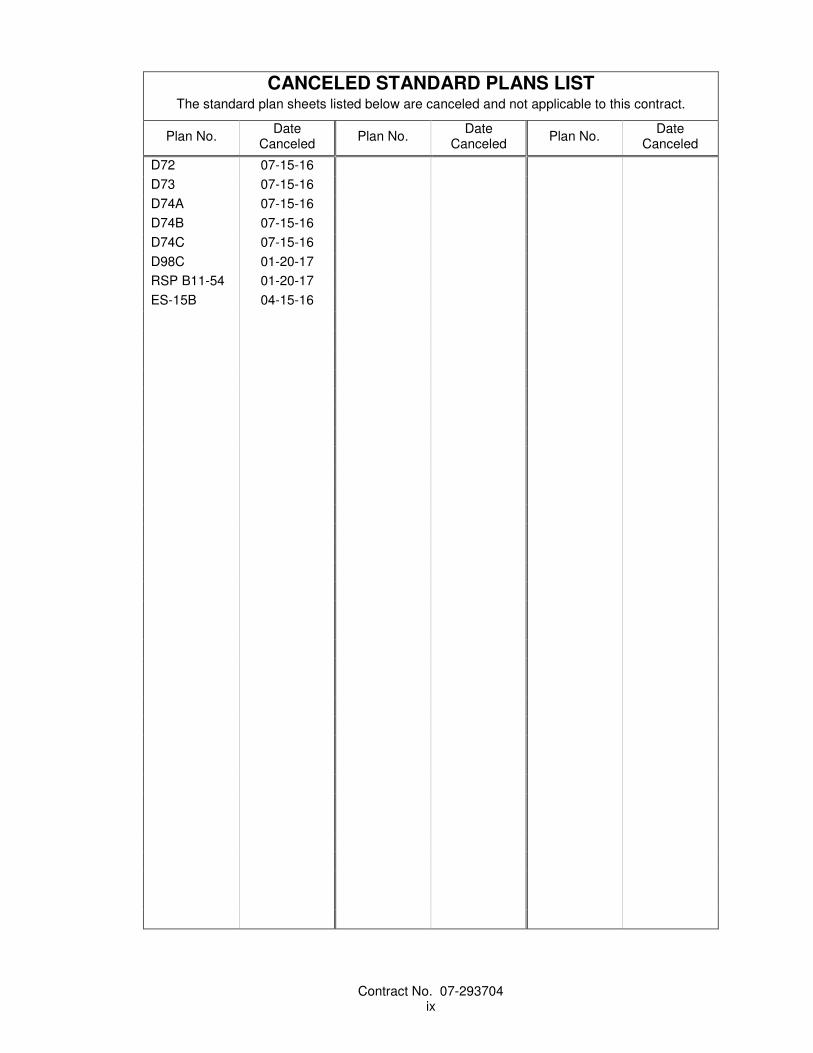


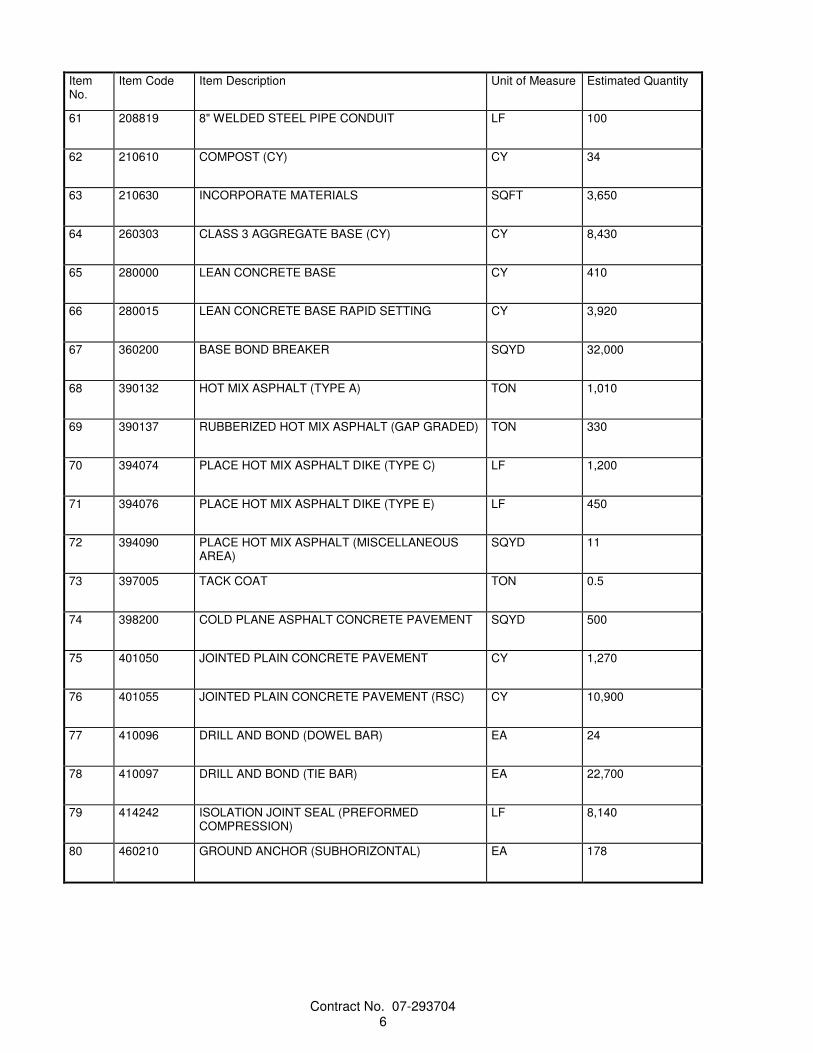
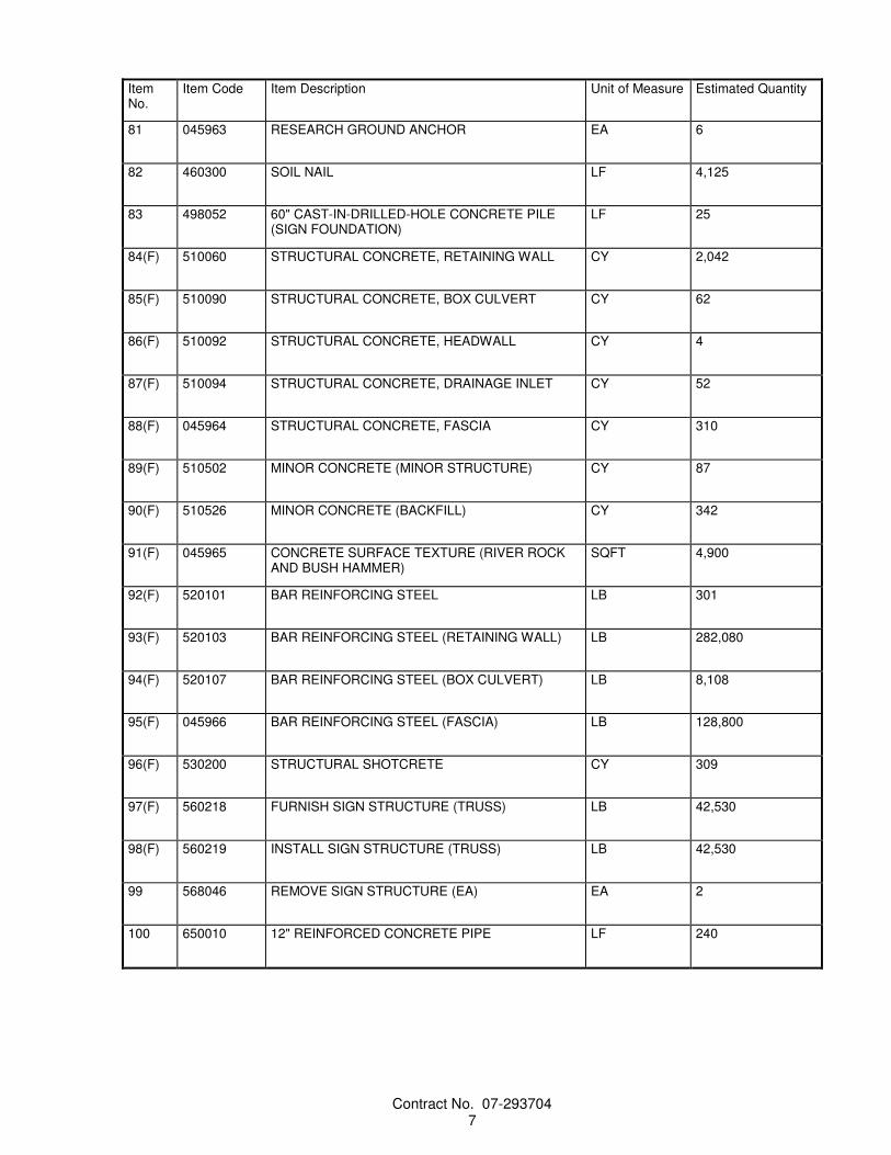


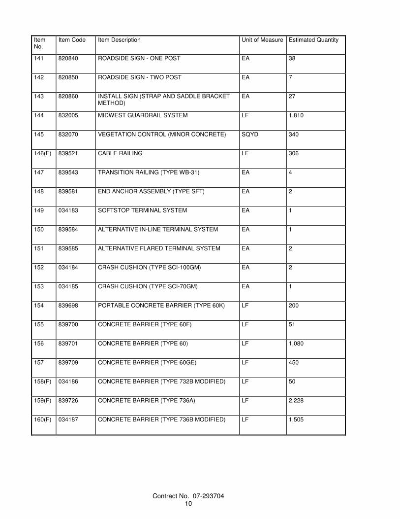

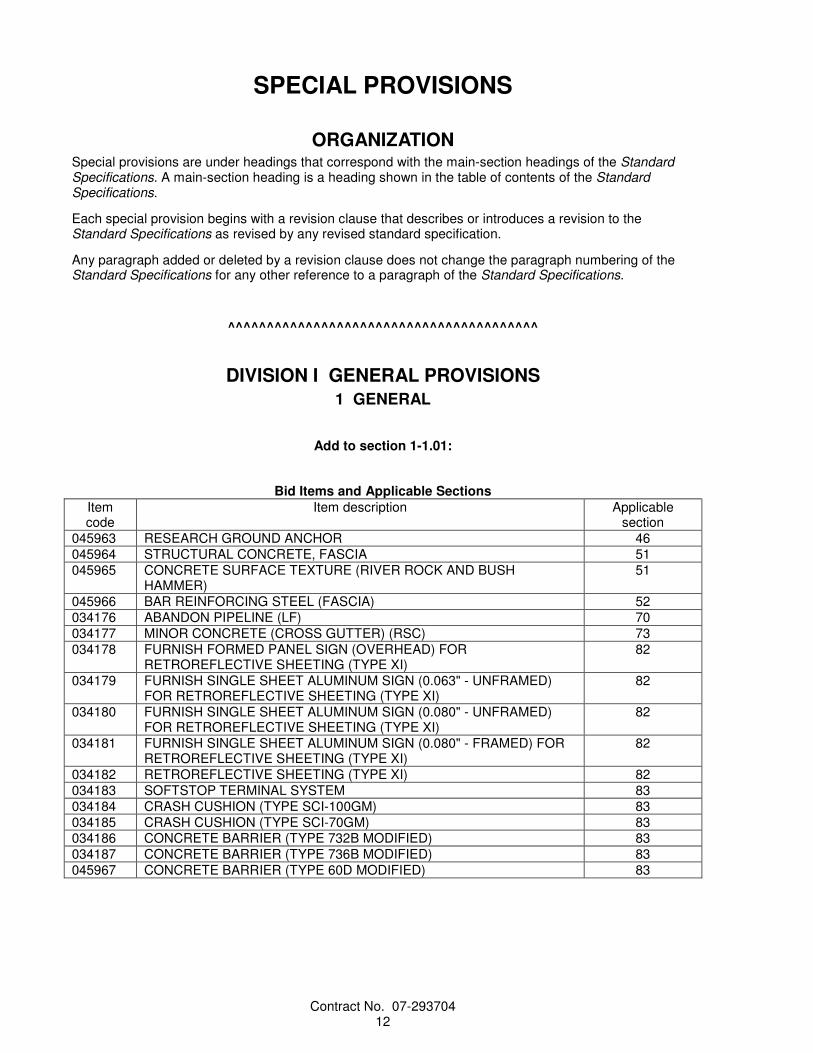


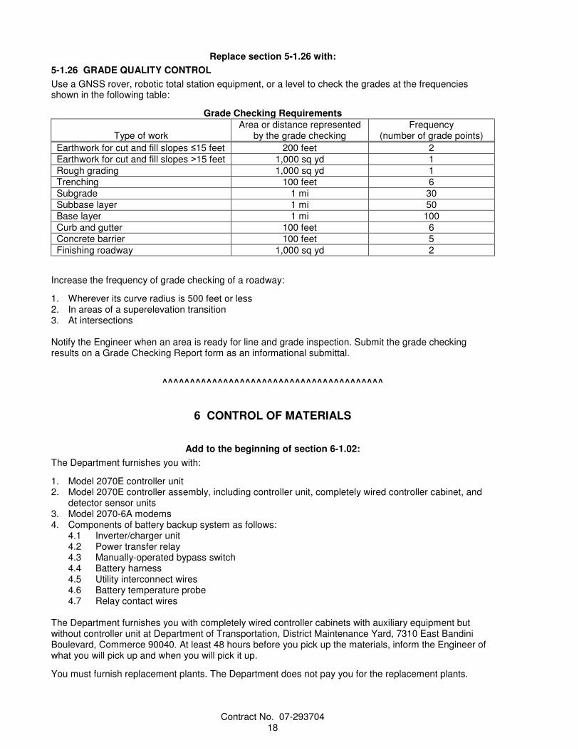


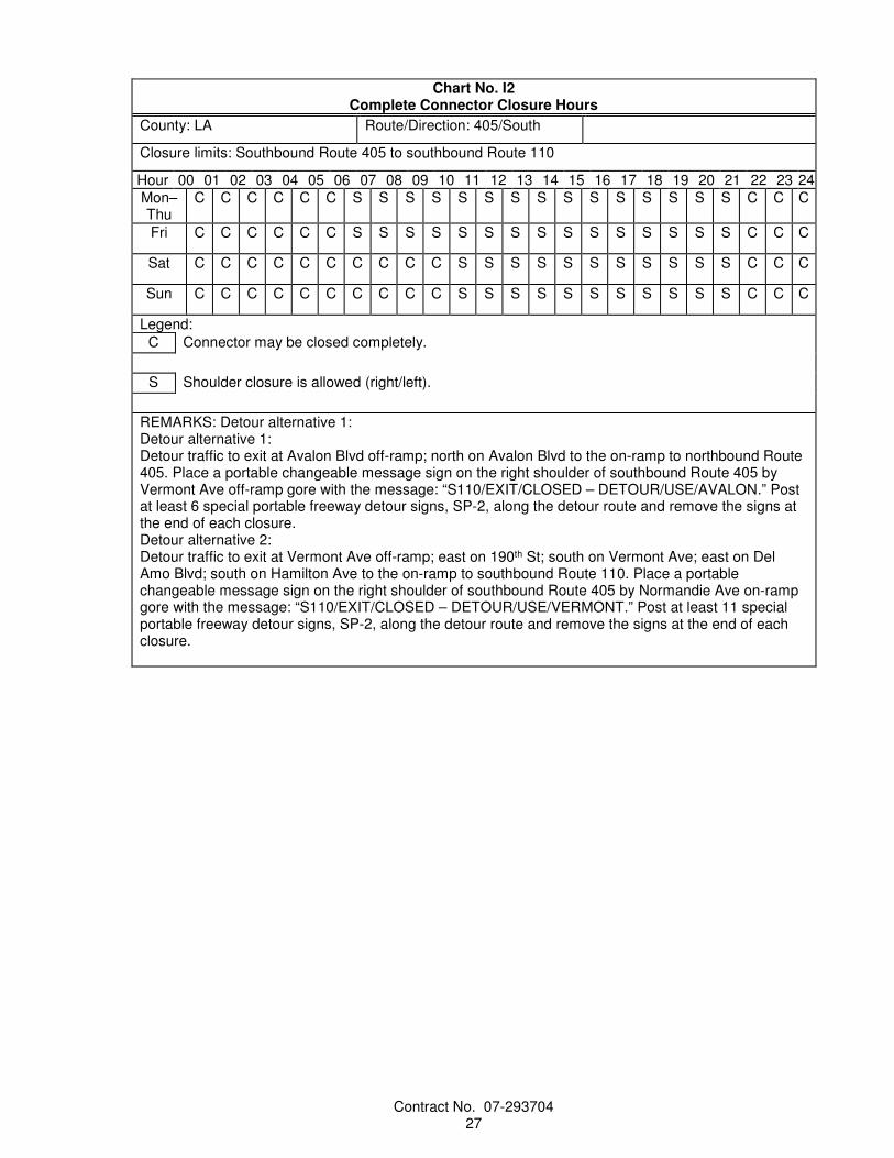


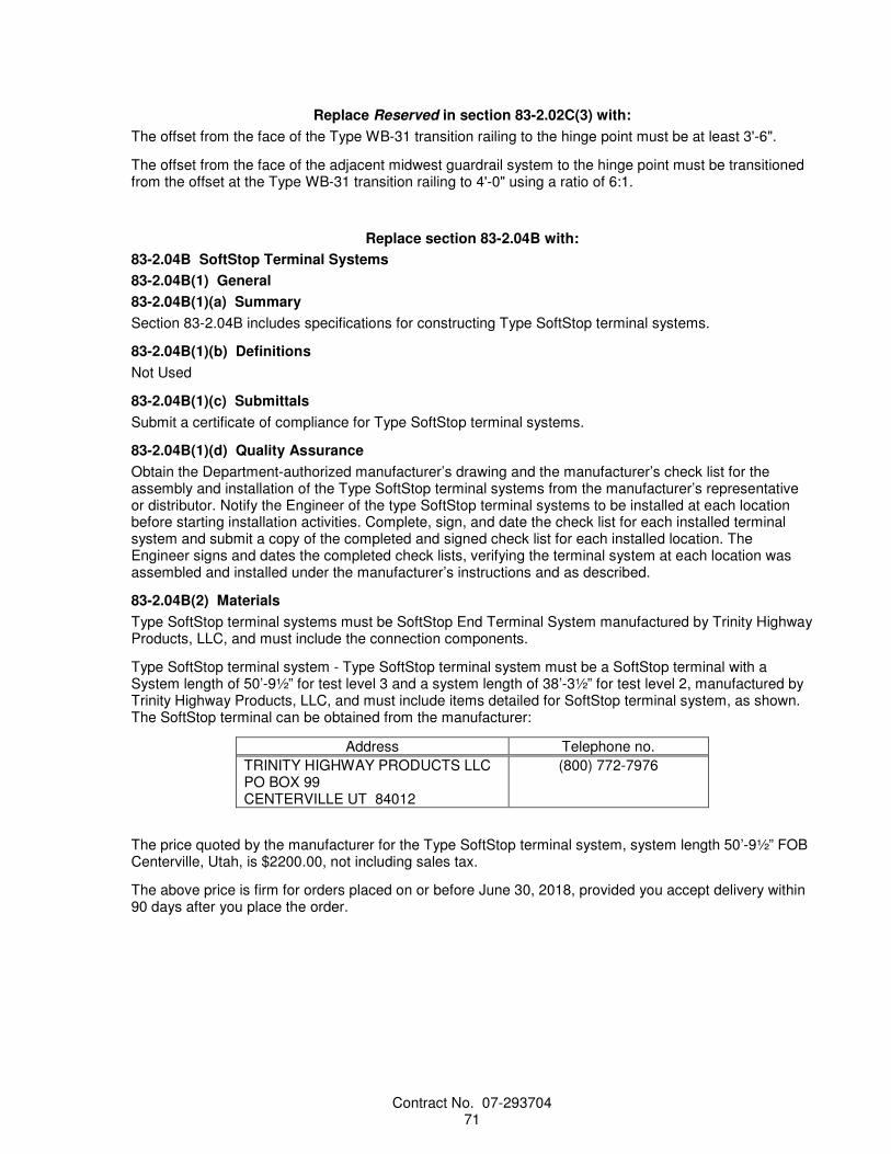

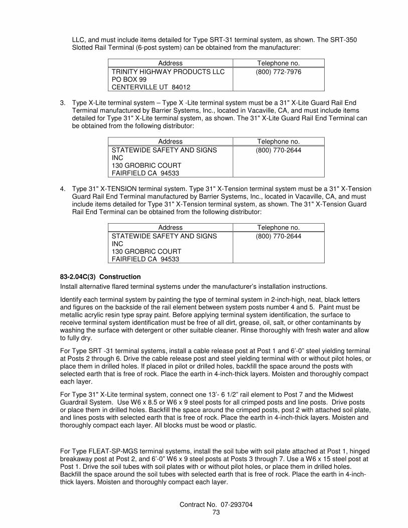


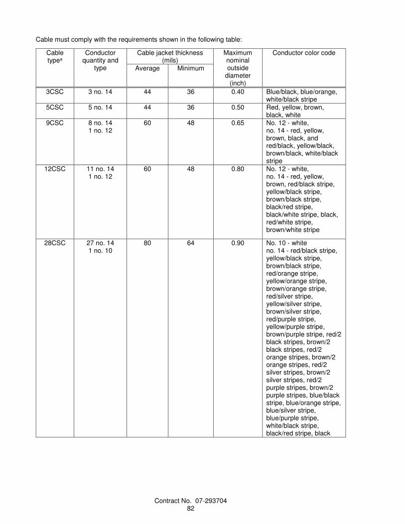


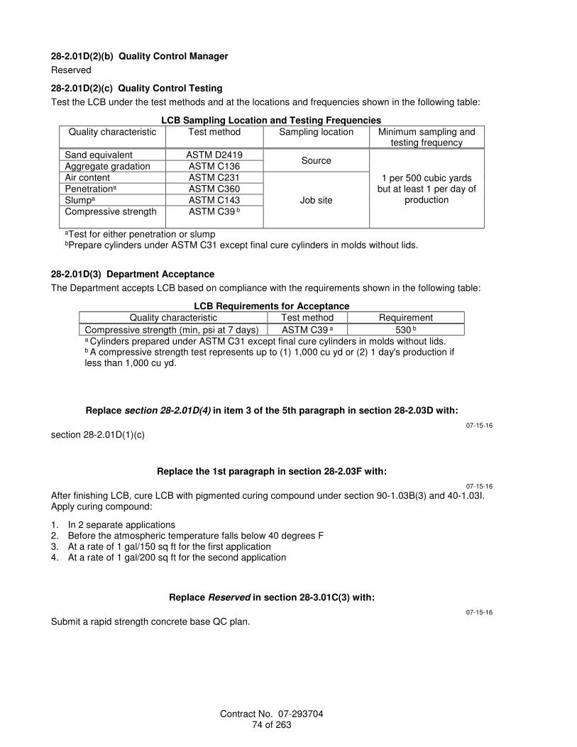


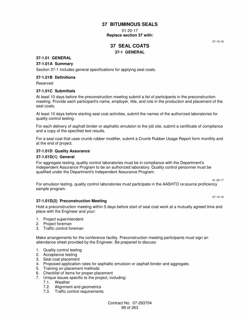

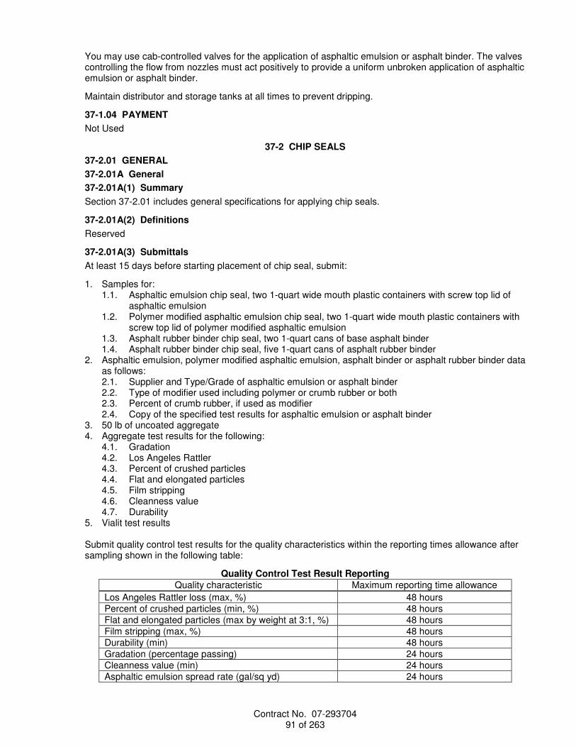

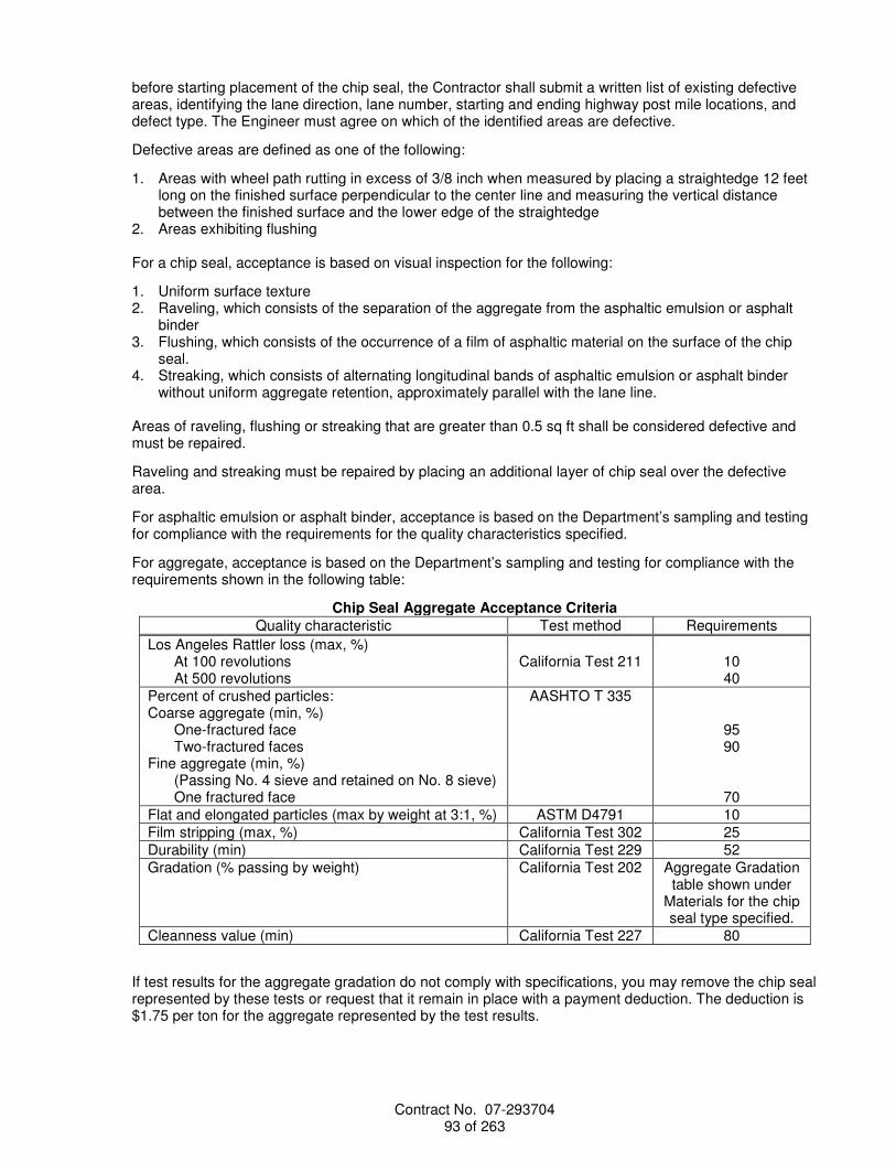

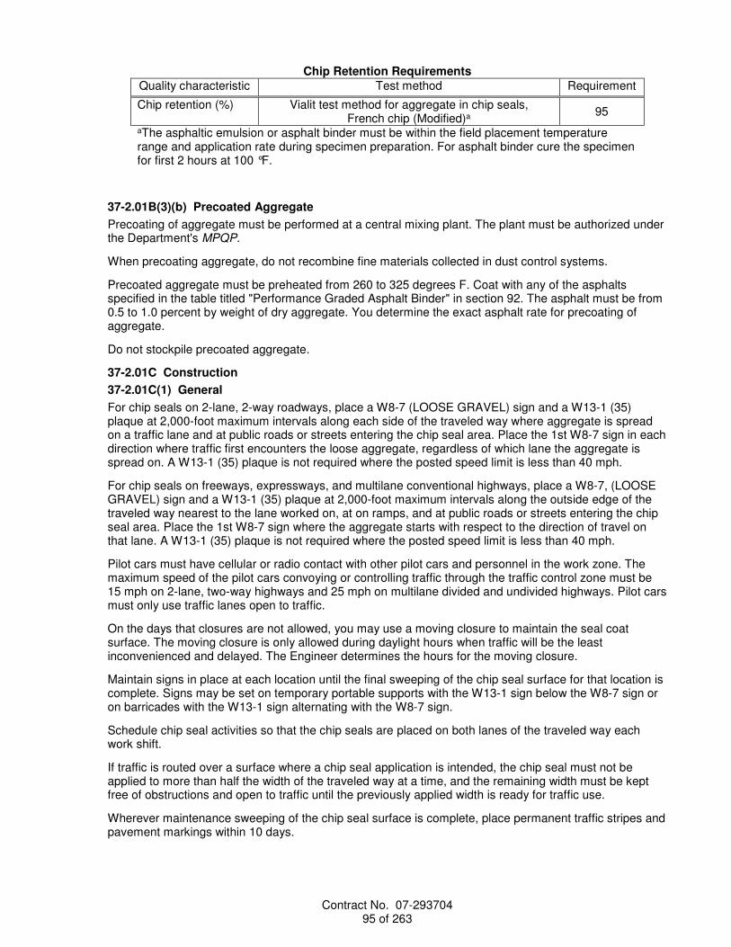

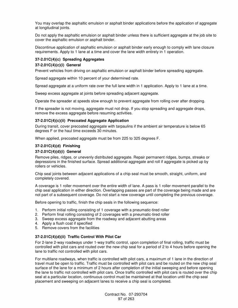


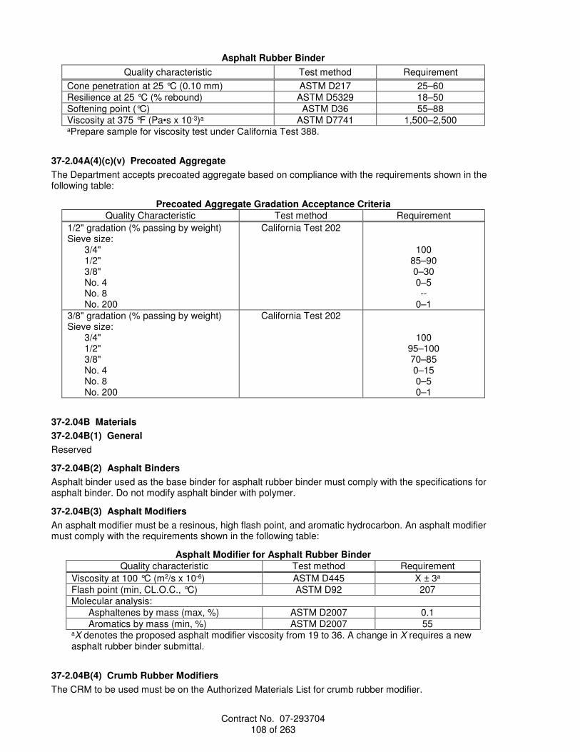


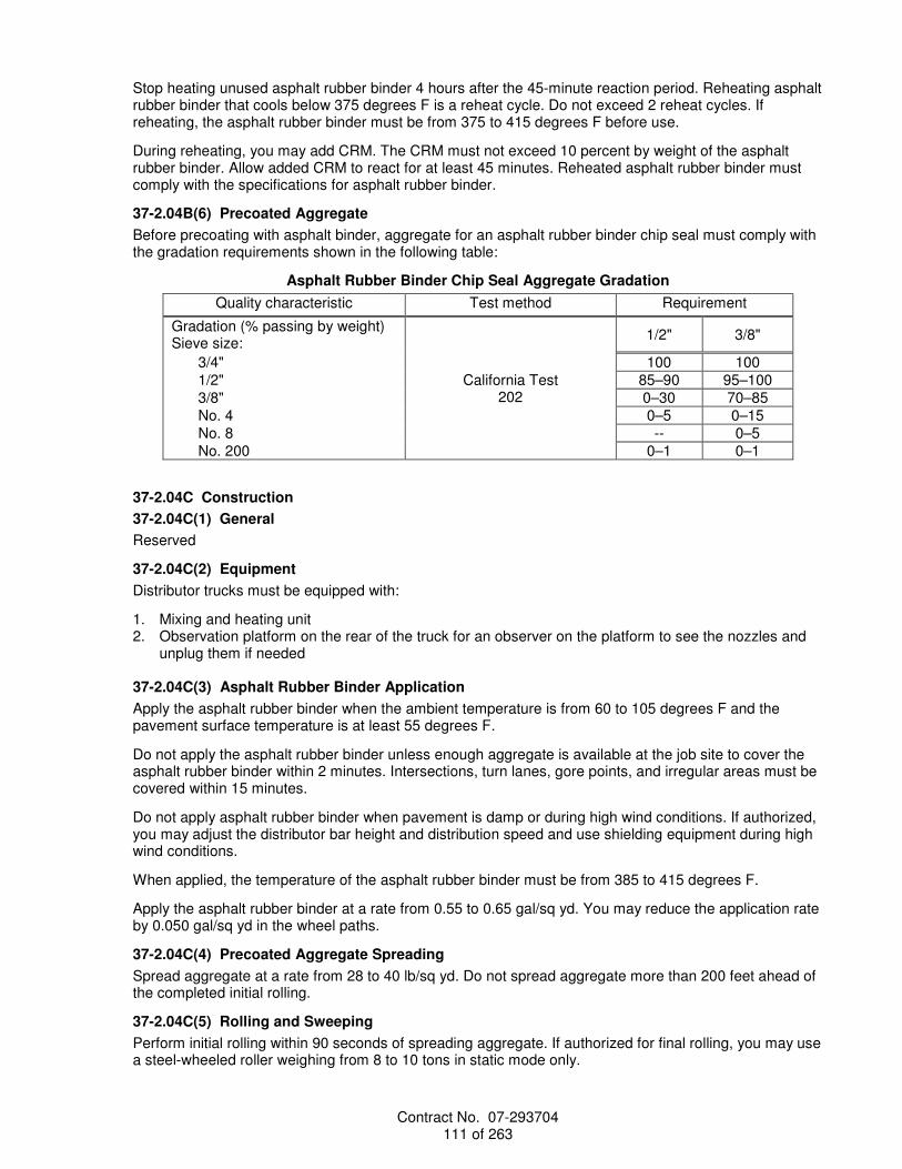


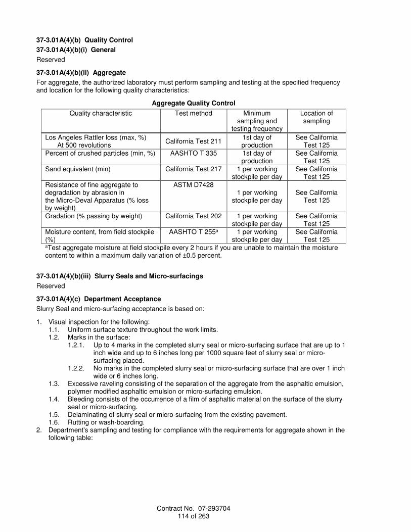


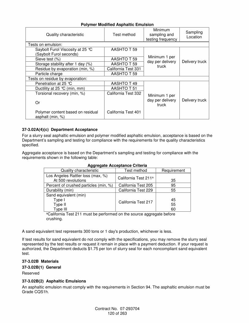


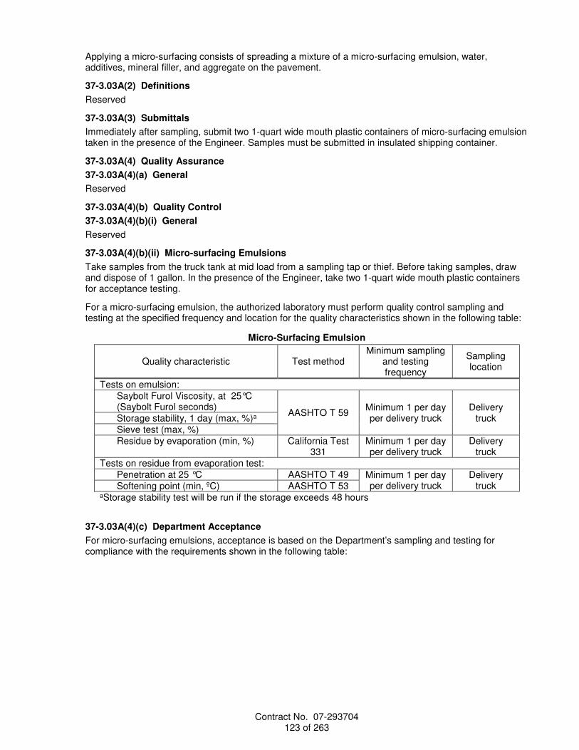


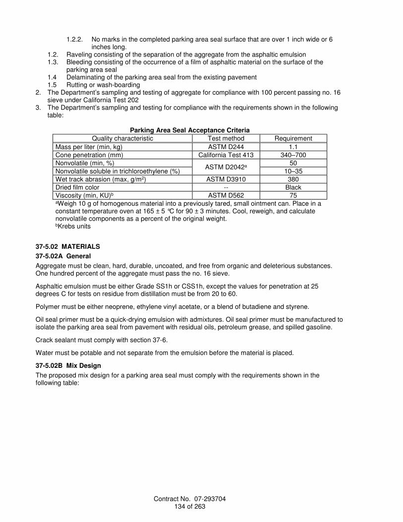


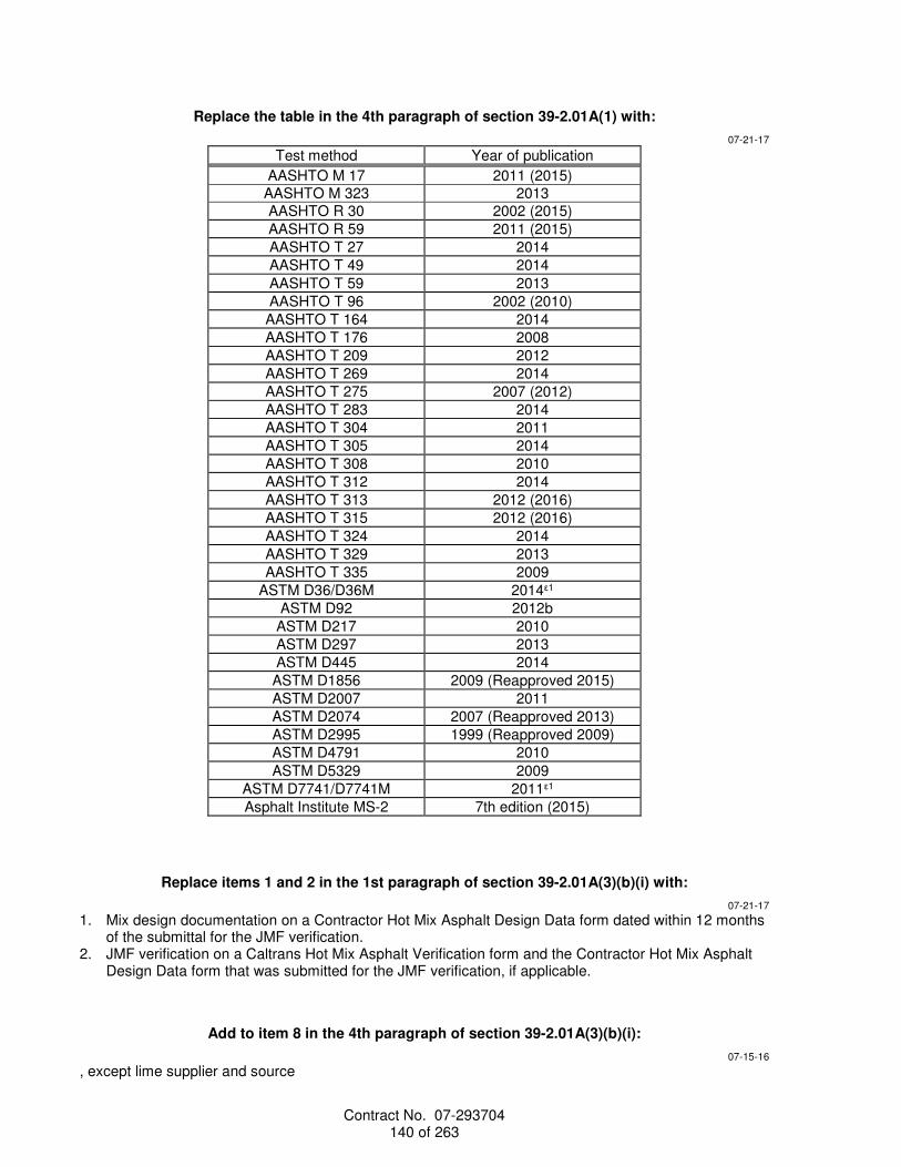


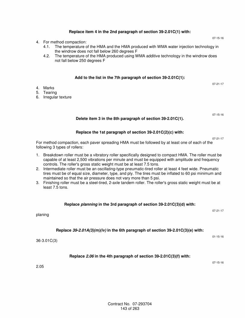


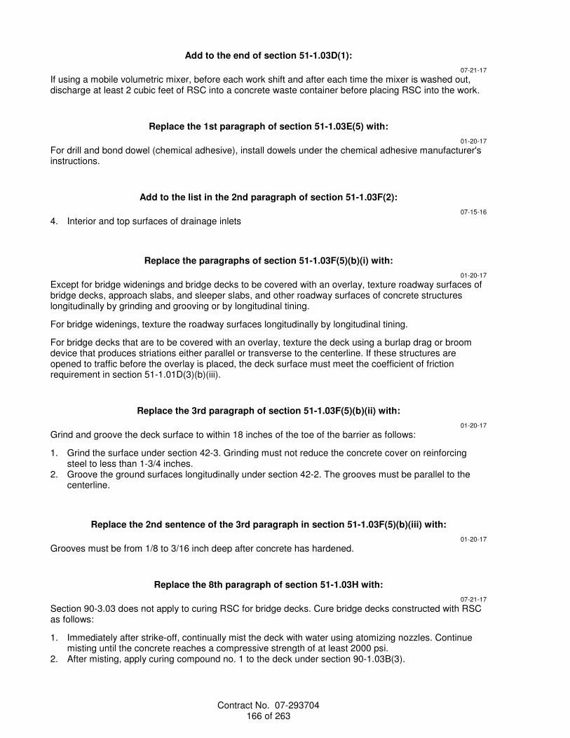

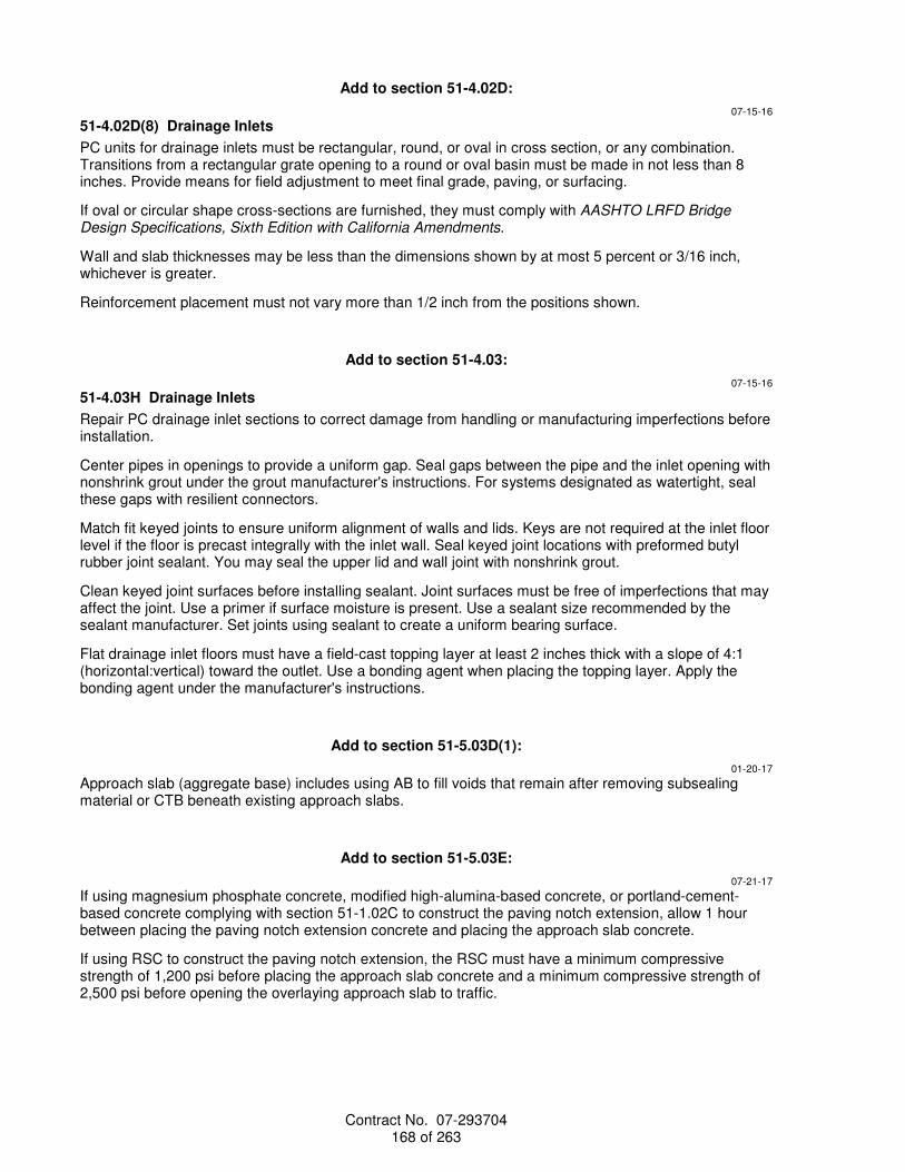


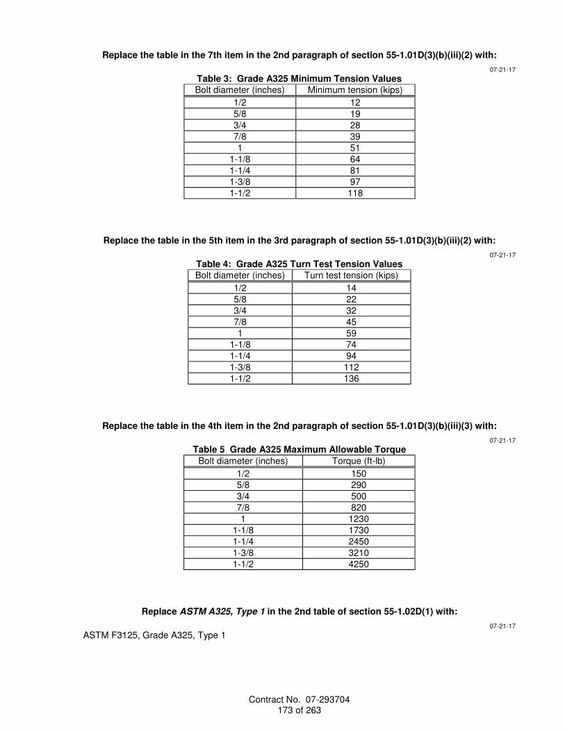
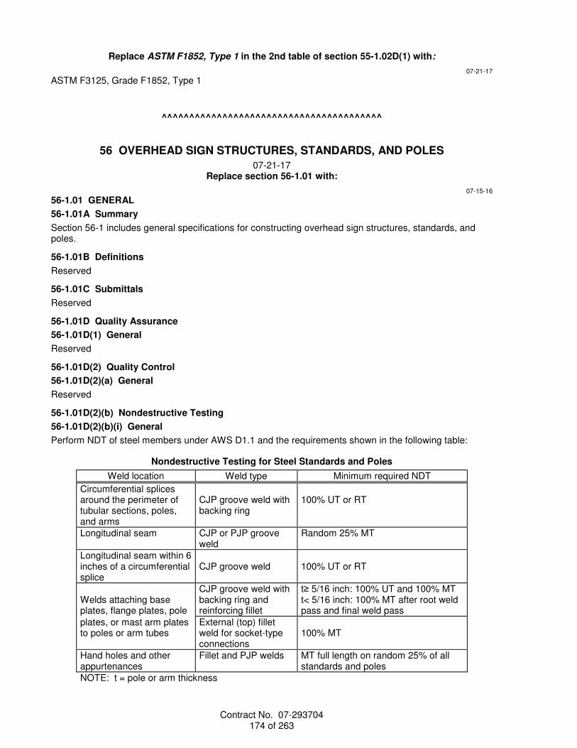
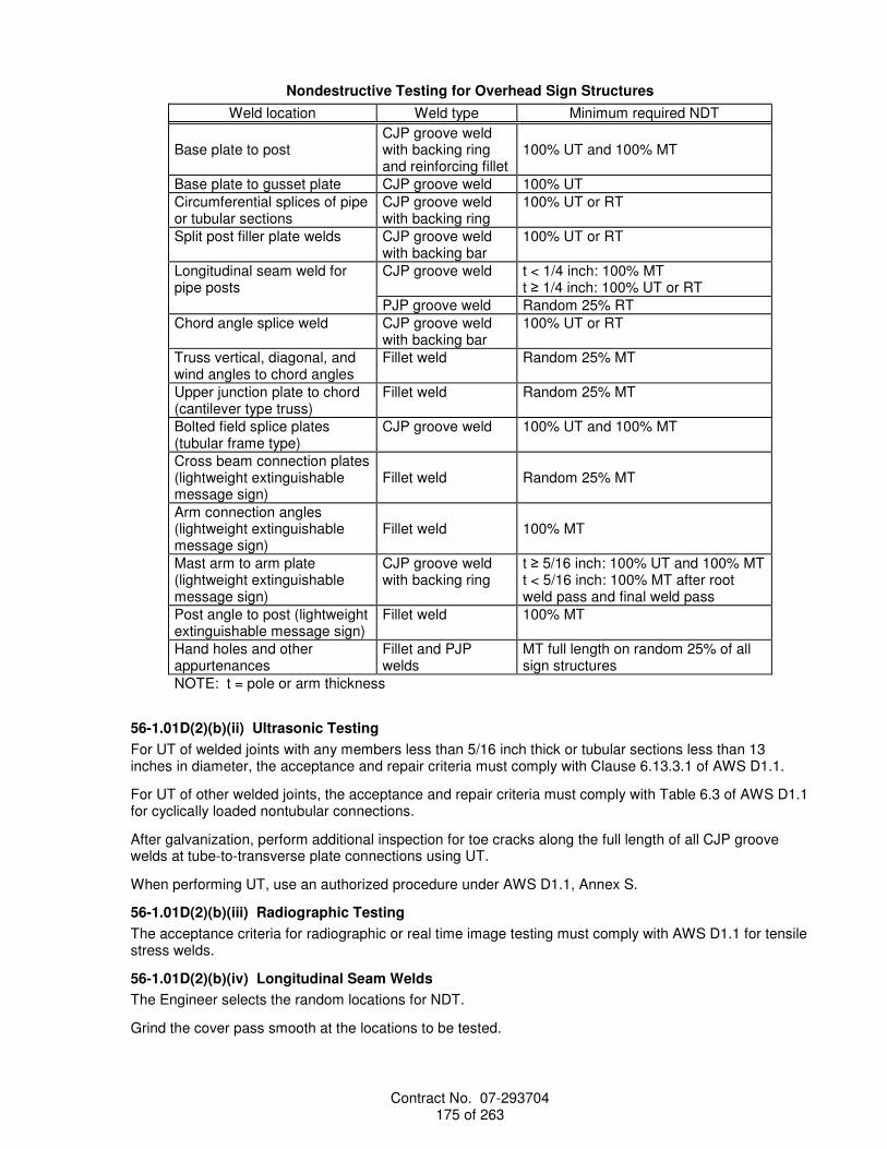


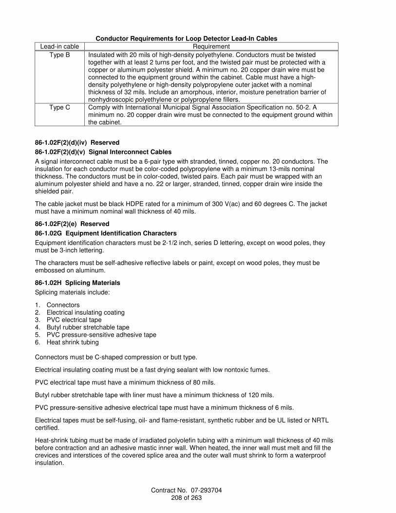


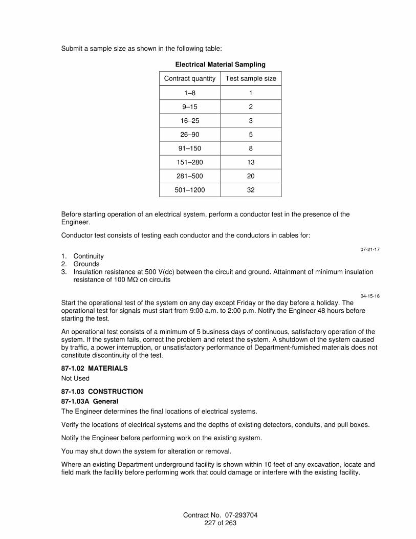


![Strategic Management Plan - Caltransdot.ca.gov/perf/library/pdf/Caltrans_Strategic_Mgmt_Plan_033015.pdf · Caltrans Strategic Management Plan[ 1 ] I am very pleased to present the](https://static.documents.pub/doc/80x56/5a7804597f8b9a1b688e6668/strategic-management-plan-caltransdotcagovperflibrarypdfcaltransstrategicmgmtplan033015pdf.jpg)


