21
Andrey Mokhov, Victor Khomenko Danil Sokolov, Alex Yakovlev Dual-Rail Control Logic for Enhanced Circuit Robustness
| Date post: | 14-Dec-2015 |
| Category: |
Documents |
| Upload: | callie-short |
| View: | 224 times |
| Download: | 0 times |

Andrey Mokhov, Victor KhomenkoDanil Sokolov, Alex Yakovlev
Dual-Rail Control Logic forEnhanced Circuit Robustness

Motivation
Source:Akgun et al, ASYNC’10
Optimal operating voltage lies near or below sub-threshold voltage
Low voltage leads to unpredictable delay variationsAsynchronous circuits can be pushed to work at lower voltagesSingle-rail asynchronous circuits are not robust enough – why?

Why not single-rail circuits?Advantages of single-rail:
Just one wire per signal: simple, natural, widely adoptedEfficient in terms of area, latency, and power consumptionExtensive tool support (PETRIFY, PUNF/MPSAT, WORKCRAFT)
Disadvantages of single-rail for low voltage operation:Often not speed-independent due to input invertersVulnerable to single-event upsets (SEU)Require significant effort to balance wire forks
Dual-rail circuits:Two wires per signal: more complex, poor tool supportNo input inverters, more robust to SEU, fewer wire forksSmall overhead in terms of area, latency, power
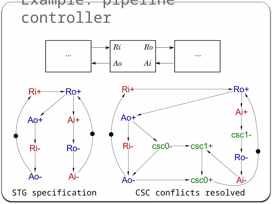
Example: pipeline controller
STG specification CSC conflicts resolved

Example: single-rail implementation
Synthesised automatically (by PETRIFY or PUNF/MPSAT)Needs big atomic gatesContains 5 input inverters

Example: single-rail implementation
Not speed-independent! Problematic trace:Ri+; Ro+; Ao+; i2-; i3-; csc0-; i4+; Ai+; i5-; csc1-; i1+; Ro-; i2+; Ri-; Ao-; i3+; Ai-; i5+; csc1+
Race between csc0+ and i1-.
Hazard onoutput Ao.
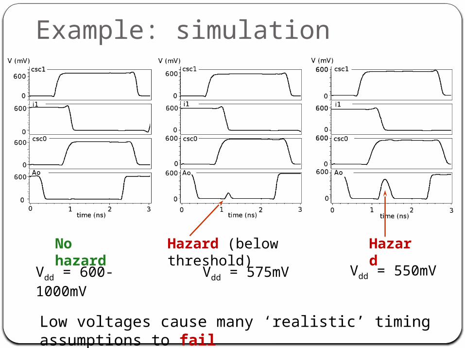
Example: simulation
Vdd = 600-1000mV Vdd = 575mV Vdd = 550mV
No hazard Hazard (below threshold) Hazard
Low voltages cause many ‘realistic’ timing assumptions to fail
Input invertersAssumed to be faster than any adversary path passing
through other logic gatesRealistic assumption under normal operating voltageCan lead to hazards due to high delay variations in low
voltage mode and/or new fabrication technology
Can be difficult to eliminate
Dual-rail encoding is the key!

Dual-rail encodingUses two physical wires to represent one logical signal:
No need for inverters: inversion is done by swapping rails:
=

Transition protocol
DR datapathspacer propagation(for comparison):

Overview of implementation styles
Complex gate (CG)Generalised-C (gC) Standard-C (stdC)
Generalised-RS (gRS) Standard-RS (stdRS)
Single-rail implementations:
Dual-rail implementations:

Basic dual-rail elements: repeater
gates transistors
Repeater insertion tominimise wire delays:
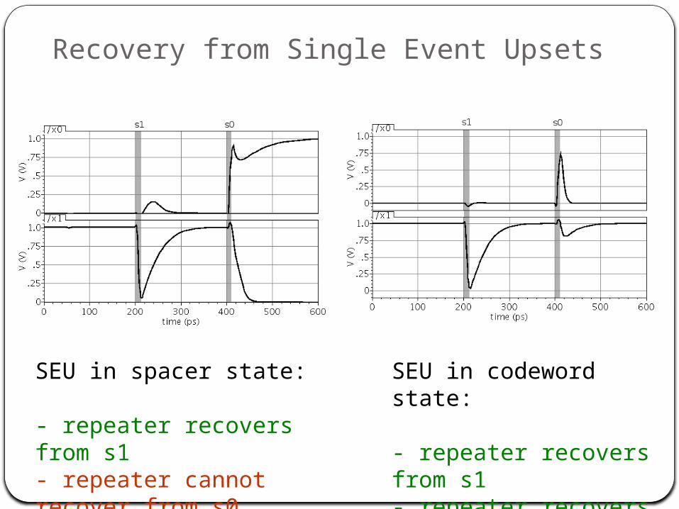
Recovery from Single Event Upsets
SEU in spacer state:
- repeater recovers from s1- repeater cannot recover from s0
SEU in codeword state:
- repeater recovers from s1- repeater recovers from s0

Basic dual-rail elements: C-element
dual-rail
Transistor-level implementations

Example: dual-rail implementation
No input inverters speed-independent!

Example: comparison
Single rail
Dual rail

Experiments: area (literals)
CG stdC stdRS gRS
Average results:
• CG 100%• stdC 189%• stdRS 151%• gRS 115%

Experiments: power (wire load)
CG stdC stdRS gRS
Average results:
• CG 100%• stdC 181%• stdRS 130%• gRS 99%
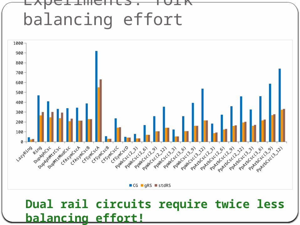
Experiments: fork balancing effort
LazyR
ingRing
Dup4phCsc
Dup4phMtrCsc
DupMtrModCsc
CfAsym
CscA
CfAsym
CscB
CfSymCscA
CfSymCscB
CfSymCscC
CfSymCscD
PpWkC
sc(2_3
)
PpWkC
sc(2_6
)
PpWkC
sc(2_9
)
PpWkC
sc(2_1
2)
PpWkC
sc(3_3
)
PpWkC
sc(3_6
)
PpWkC
sc(3_9
)
PpWkC
sc(3_1
2)
PpArbCsc(
2_3)
PpArbCsc(
2_6)
PpArbCsc(
2_9)
PpArbCsc(
2_12)
PpArbCsc(
3_3)
PpArbCsc(
3_6)
PpArbCsc(
3_9)
PpArbCsc(
3_12)
0
100
200
300
400
500
600
700
800
900
1000
CG gRS stdRS
Dual rail circuits require twice less balancing effort!
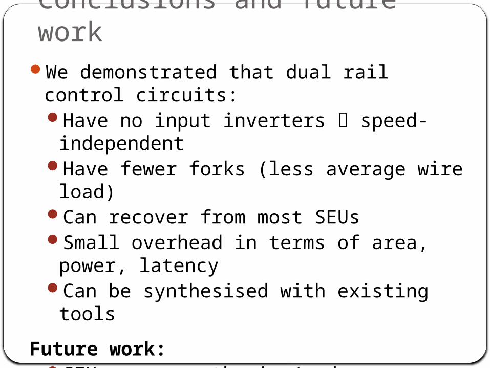
Conclusions and future workWe demonstrated that dual rail control circuits:
Have no input inverters speed-independentHave fewer forks (less average wire load)Can recover from most SEUsSmall overhead in terms of area, power, latencyCan be synthesised with existing tools
Future work:SEU-aware synthesis (reduce spacer period)RS-latch testabilityExploring multi-valued control logic (> 2 rails)

Thank you!


