42
Android Electro Cardio Monitor Jeffrey Frye - EE Jonathan Gibson - EE Michael Sun - CpE Cheng-Chieh (Jay) Wang - EE Group 22 Sponsored by: CECS Alumni Chapter ($150)
| Date post: | 24-Dec-2015 |
| Category: |
Documents |
| Upload: | domenic-campbell |
| View: | 213 times |
| Download: | 0 times |

Android Electro Cardio Monitor
Jeffrey Frye - EEJonathan Gibson - EEMichael Sun - CpECheng-Chieh (Jay) Wang - EE
Group 22
Sponsored by: CECS Alumni Chapter ($150)

Project Motivation
● Medical professionals need a new strategy for recording the vital signals of their patients.
● The results of an ECG are essential data that should be portable so the patient and family can be able to view the heart rate signals.
● Mobile platform for the ECG system

Project Goals and Objectives
● Heart Rate Simulatoro Design and implement a heart rate simulator
using previous patients’ records.● The Analog Front End Circuit
o Filter out any interference and isolate the desired signal from the simulator to be amplified.
● Electro Cardio Appo Receive heart rate signal via Bluetooth and
display on Android device.
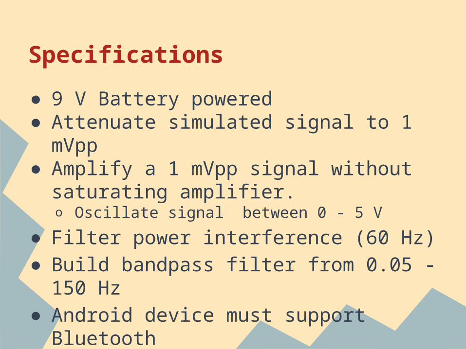
Specifications
● 9 V Battery powered● Attenuate simulated signal to 1 mVpp● Amplify a 1 mVpp signal without
saturating amplifier.o Oscillate signal between 0 - 5 V
● Filter power interference (60 Hz)● Build bandpass filter from 0.05 - 150
Hz● Android device must support Bluetooth
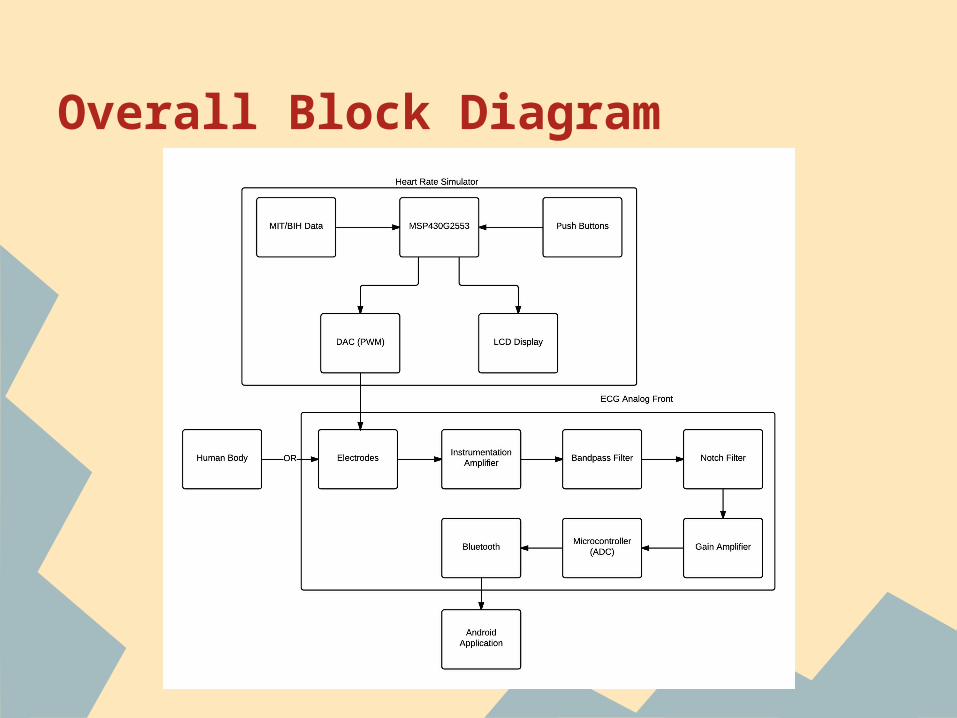
Overall Block Diagram

Heart Rate Simulator
● Simulate an actual heart signal● Read in data files from an online
database● Output an authentic heart rate signal
to the next subsystem to be read
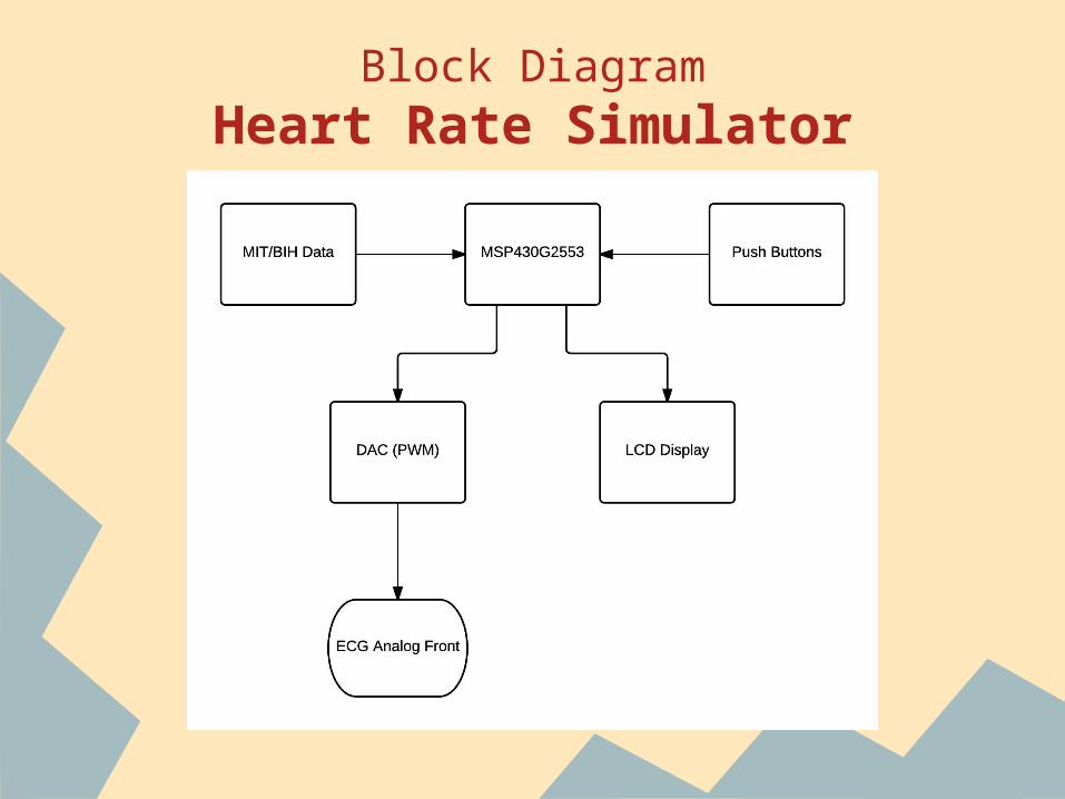
Block DiagramHeart Rate Simulator

MIT/BIH Data
● PhysioBank - online source with various different databases all available for free.
● Data can be viewed as a text document for our use.
● Three signals chosen from:o Normal Sinus Rhythm, Arrhythmia, and QT
Databases

Microcontroller
● MSP430G2553, used in Launchpad
CPU speed Up to 16 MHz
Flash Memory 16 KB
Analog to Digital Converter (ADC)
8 channel, 10-bit
Random Access Memory (RAM) 512 B
Communication Up to 1 I2C, 2 SPI, 1 UART
Pins 20 pins
Timers 2 16-bit Timers

Push Buttons
● Simple pull-up configuration● Simple circuit for debouncing● Using time constant of 3.3ms

LCD Screen● Allow user to scroll through options
using external push buttons and select which heart rate test signal to send.
● 3.3 V● 16x2 characters● Send data in 4-bit mode

Pulse Width Modulation● We use pulse width modulation (PWM) to act as a
DAC.● The PWM signal outputs are variable duty cycle
square waves with 3.3V amplitude.● Realizing D/A output from a PWM signal - analog
low pass filter the PWM output to remove most of the high frequency components, leaving the DC component.

External Storage
● MSP430 only has 16KB of flash memory.
● Decided to use SD/MMC Card● Unable to get MSP430 to read from SD
card● Alternate solution - repeat a few
periods of each signal

Heart Rate Simulator PCB Layout

Analog-Front Design
● Instrumentation Amplifier● Low pass filter● High pass filter● Notch filter● Gain Amplifier

Block DiagramAnalog Front End Circuit

ECG Signal

ECG signal Spectrum

Stage 1- Instrumentation Amplifier
● Common-mode noise: Radiations from Power, DC offset, muscle noise
● The amplification circuitry provide a CMRR of better than 60dB.

Stage 2- Low Pass Filter
● Cut-off frequency is set to 150 Hz● The low pass filter cut-off frequency
range allows us to view the complete spectrum contained within the ECG signal.
● The filter was designed using Sallen-Key topology. It is a 4th order cascaded filter.
● Op amp chosen is a TL084CN which offers low noise, high CMR, low power.

Stage 3- High Pass Filter● Cut-off frequency is set to 0.05 Hz● The high pass filter limits DC
wandering caused by electrical activity in the body.
● The combination of the lowpass and highpass filter creates a bandwidth from 0.05 Hz - 150 Hz. Referred to as diagnostic mode. This allows us to view more detailed segments of the ECG signal.
● Monitor mode has a bandwidth from 1 Hz to 40 Hz. Typically, used for quick ECG analysis.

Stage 4- Notch Filter

Notch Filter Frequency Response

Stage 5- Unity Gain Amplifier
● Total Gain of circuit ~4000.● The final output of the Analog front is
between 0 to 5V.● Non-Inverting terminal of op-amp has a
DC offset of 1.5 volts to boost up the signal in the range of 0 to 5V.
● Inverting terminal takes in the input of the notch filter.
● The output of the op-amp has a diode to block negative voltage values.

PCB Layout- Analog Front

Analog to Digital Converter
● The signal should be sampled at a rate of not less than 120 Hz.
● The signal should be amplified to be almost 1 V.
● We decided to use Built-in ADC from Atmel ATtiny85

Atmel ATtiny85
● 2.7 - 5.5 V operating voltage● 10-bit ADC● 8 MHz internal clock speed● 8k bytes programmable memory● 8-pin PDIP● 6 bi-directional I/O ports● Arduino IDE

Digital Filter - Median Filter
If the exact value is [2 80 6 3],y[1] = Median[2 2 80] = 2,y[2] = Median[2 80 6] = 6,y[3] = Median[80 6 3] = 6,y[4] = Median[6 3 3] = 3.
so the final output is [2 6 6 3].
Arduino Library credit to Jeroen Doggen

Filtering Signal
Before Median Filter
After Median Filter

Bluetooth SpecificationProduct Model HC-06 with Backboard
(Only support Bluetooth V2.1)
Size (cm) 3.5*1.5
Power 5VDC 50 mA
Service Slave only
Price $10.67 for 2

Microcontroller and Bluetooth PCB Schematics and Layout

Power Management
PART VOLTAGE CURRENT (max)
MSP430 3.3 V 0.4 mA
16x2 LCD 3.3 V 2.5 mA
Atmel ATtiny 5V 5 mA
HC-06 Bluetooth 5 V 50 mA
INA128P 5 V .7 mA
TL084CN 5 V 1.4 mA

Power Block Diagram

MobileAppBlockDiagram

GUI

GUI

Sending/Receiving Data
● Needed to create a separate thread (ConnectThread) for connecting Bluetooth module and Android device
● ConnectThread takes in BluetoothDevice and creates a BluetoothSocket
● We need yet another thread (ConnectedThread) to utilize InputStream & OutputStream for reading in data
● Handler handles the processing of data and displays heart rate signal

GraphView
GraphView - Open source graph plotting for Android
We imported the GraphView library and used it to display a graph in real time.
Credit to: Jonas Gehringwww.android-graphview.org

Item Quantity Price ($) Vendor
INA128 2 13.00 ebay
Green 16 pin LCD 1 4.95 ebay
TL084CN 10 3.99 ebay
ATTiny85 2 3.99 ebay
Electrodes 50 7.89 ebay
SD Card Breakout Many 9.95 Sparkfun
Sensor Cable 1 4.95 Sparkfun
Miscellaneous Many 20.00
Bluetooth Module 2 10.76
MSP430 Launchpad 1 FREE
PCBs 9 136.00 OSH Park
Total 215.48
Expenses
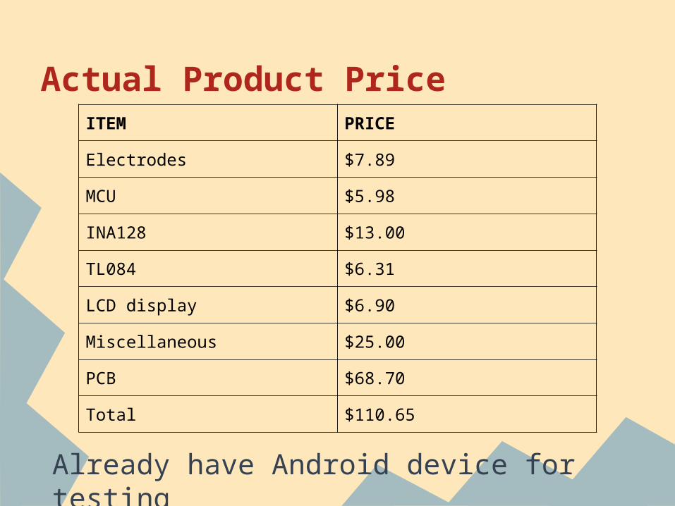
Actual Product Price
Already have Android device for testing
ITEM PRICE
Electrodes $7.89
MCU $5.98
INA128 $13.00
TL084 $6.31
LCD display $6.90
Miscellaneous $25.00
PCB $68.70
Total $110.65

Group Responsibilities
Jeffrey Frye Jonathan Gibson
Michael Sun Jay Wang
Heart Rate Simulator
■ □
ECG Sensor □ ■
Power System ■
Bluetooth Communication
■ □
Android Application
□ ■
■ - Main Responsibility□ - Partial Responsibility

Questions


