A New Algorithm for Crack Localization in a Rotating Timoshenko Beam AHMAD A. MASOUD Department of Electrical Engineering, King Fahd University of Petroleum & Minerals, P.O. Box 287, Dhahran 31261, Saudi Arabia SAMER AL-SAID Department of Mechanical Engineering, King Saud University, P.O. Box 800, Riyadh 11421 Riyadh, Kingdom of Saudi Arabia ([email protected].) (Received 24 October 2006accepted 22 July 2008) Abstract: In this paper a new crack localization algorithm based on a mathematical model describing the lateral vibration of a rotating cracked Timoshenko beam is proposed. The Lagrange equation and the assumed mode method are used to derive the model. The localization algorithm utilizes the variation in a single natural frequency of the beam versus a few rotor speed values to detect and localize a crack. The algorithm has different means of checking/reconfirming its crack estimate. This may be used to improve the accuracy of the decision. Also, the effect of rotational speed and crack location on the system’s dynamical characteristics is investigated using the derived mathematical model. The results are compared with those obtained from a three-dimensional finite-element analysis. Good agreement is observed between the two sets of results. Finally, the reliability of the identification algorithm is established using the data obtained from the finite- element analysis. Keywords: Crack localization, nondestructive test, cracked beam, rotating beam. 1. INTRODUCTION During the last two decades, the focus of many researchers was on improving damage- revealing techniques for vibrating structures such as aircraft structures, large space struc- tures and structures used in an ocean environment. Damage in the form of cracks can occur in structures owing to their limited fatigue strengths. It could also result from the manufac- turing process. During structural vibration these cracks may grow over time to a level where they could pose a threat to the integrity of the structure. Therefore, they should be located and repaired at an early stage before they propagate and harm the structure. It has been reported in the literature that a crack does change the dynamical characteristics of a system. It is also considered to be one of the parameters for mode localization in a blade-disk or a periodic system. In these systems, a crack significantly affects the vibrational modes by changing them from the uniform modes to the localized modes. Such mode localization may, in turn, confine the vibrational energy in the vicinity of the cracked blade. Owing to the large cyclic Ahmad A. Masoud, Samer A. Al-Said, "A New Algorithm for Crack Localization in a Rotating Timoshenko Beam", Journal of Vibration and Control.2009; 15: 1541-1561 .
Transcript
A New Algorithm for Crack Localization in a RotatingTimoshenko Beam
AHMAD A. MASOUDDepartment of Electrical Engineering, King Fahd University of Petroleum & Minerals, P.O. Box287, Dhahran 31261, Saudi Arabia
SAMER AL-SAIDDepartment of Mechanical Engineering, King Saud University, P.O. Box 800, Riyadh 11421Riyadh, Kingdom of Saudi Arabia ([email protected].)
(Received 24 October 2006� accepted 22 July 2008)
Abstract: In this paper a new crack localization algorithm based on a mathematical model describing thelateral vibration of a rotating cracked Timoshenko beam is proposed. The Lagrange equation and the assumedmode method are used to derive the model. The localization algorithm utilizes the variation in a single naturalfrequency of the beam versus a few rotor speed values to detect and localize a crack. The algorithm hasdifferent means of checking/reconfirming its crack estimate. This may be used to improve the accuracy ofthe decision. Also, the effect of rotational speed and crack location on the system’s dynamical characteristicsis investigated using the derived mathematical model. The results are compared with those obtained froma three-dimensional finite-element analysis. Good agreement is observed between the two sets of results.Finally, the reliability of the identification algorithm is established using the data obtained from the finite-element analysis.
During the last two decades, the focus of many researchers was on improving damage-revealing techniques for vibrating structures such as aircraft structures, large space struc-tures and structures used in an ocean environment. Damage in the form of cracks can occurin structures owing to their limited fatigue strengths. It could also result from the manufac-turing process. During structural vibration these cracks may grow over time to a level wherethey could pose a threat to the integrity of the structure. Therefore, they should be located andrepaired at an early stage before they propagate and harm the structure. It has been reportedin the literature that a crack does change the dynamical characteristics of a system. It is alsoconsidered to be one of the parameters for mode localization in a blade-disk or a periodicsystem. In these systems, a crack significantly affects the vibrational modes by changingthem from the uniform modes to the localized modes. Such mode localization may, in turn,confine the vibrational energy in the vicinity of the cracked blade. Owing to the large cyclic
Ahmad A. Masoud, Samer A. Al-Said, "A New Algorithm for Crack Localization in a Rotating Timoshenko Beam", Journal of Vibration and Control.2009; 15: 1541-1561 .
fatigue generated during operation, the interaction between this localized vibration and thepropagation of the crack may cause the blade to fatally fail.
There are several techniques for nondestructive testing available for crack detection, suchas visual examination, radiographic tests, ultrasonic testing, liquid penetration tests, X-raystest and magnetic particle tests. These methods are costly and cannot be utilized while thestructure is in operation. Owing to these limitations it is now believed that the monitoring ofthe global dynamics of structures offers a promising alternative for damage detection.
The fact that a crack or a local defect affects the dynamical response of a structure iswell known. The modal parameters such as natural frequencies and mode shapes can beused to discover the initiation and growth of fatigue-induced cracks. Numerous attempts toquantify local defects have been reported in the literature. Several researchers utilize thechanges in the system’s dynamical behavior as a diagnostic tool for damage detection inbeams. The motivation for this is the identification of cracks in a beam, which provides apoint of reference to test the accuracy of the proposed identification techniques. Also, manymechanical systems have dynamic behavior similar to a single beam (e.g. shafts, bladesand robot arms). Several authors (e.g. Wauer, 1990� Dimarogonas, 1996� Doebling et al.,1998� Chasalevris and Papadopoulos, 2006) have presented comprehensive state-of-the-artreviews on the subject. These papers provide a two-decade review of the structural crackdetection methods, which utilize the changes in a structure’s dynamical characteristics. Inthe following, additional work concerning the vibration of a cracked Timoshenko beam isreviewed.
Mei et al. (2006) used the wave propagation approach to study free and forced vibrationof an axially loaded cracked Timoshenko beam. They derived transmission and reflectedmatrices for different types of beam faults such as cracks, flexible boundaries and changesin beam section. The effects of crack depth, location, axial load and step section change onthe dynamical characteristics of a Timoshenko beam were investigated numerically.
Masoud et al. (1998) derived a mathematical model describing the lateral vibrationof a fixed–fixed cracked beam under constant axial loading using modal analysis. Theyalso studied the interaction between the crack depth and axial load, and the effect of thisinteraction on the natural frequencies of the system. The theoretical results obtained wereverified experimentally.
Fang et al. (2006) developed analytical solutions describing free and forced vibrationsof a bladed-disk system with a single cracked blade. A simple system of Euler–Bernoullicantilevered beams (blades) connected by springs was used. The effect of a crack on the sys-tem dynamical characteristics was investigated showing that even for a small crack, vibrationmode localization and forced response localization are present.
Kuang and Huang (1999) conducted a similar study where they used the Galerkin methodto derive the equation of motion for a rotating shrouded bladed-disk system with a singleblade crack. The blades were modeled as Euler–Bernoulli beams, while the cracked beamwas modeled as two-span beam connected with a torsional spring. Numerical solutions wereobtained to show the effect of crack depth, location and rotational speed on the dynamiccharacteristics of the system. The results indicate that blade crack can be considered as areason for the localization phenomenon found in rotating bladed disks.
Huang (2006) used Hamilton’s principle to derive the governing equations of motion forrotating shrouded pre-twisted cracked blades. The discrete equations of motion were solvednumerically using the Galerkin method. The Euler–Bernoulli beam model was employed
to characterize the tapered pre-twisted blade. They showed that the number of blades mayinfluence the localization frequency and vibration in the bladed-disk system. The study alsorevealed that localization modes in the system are significantly affected by the number andthe distribution of cracked blades in the mistuned system. Moreover, increasing the numberof cracked blades enhances mode localization.
A crack identification technique for a rotating thick blade was proposed by Chang andChen (2004). Their technique was based on spatial wavelet analysis, where a finite elementmodel was derived to calculate the mode shapes for the rotating cracked blade and thesemode shapes were analyzed using the wavelet transform. They showed that the distributionsof the wavelet coefficients can identify the crack position.
A finite spectral Timoshenko beam element with a transverse open, nonpropagatingcrack was proposed by Krawczuk et al. (2003). The crack was simulated by a masslessspring that has bending and shear flexibilities which were calculated using Castigliano’s the-orem and the laws of fracture mechanics. They used the element for beam modal analysis aswell as wave propagation analysis. The derived element has the ability to analyze the beamover a very wide range of frequencies. Consequently, high natural frequencies can be calcu-lated simply. This leads to accurate crack detection since very small cracks cause measurablechanges in high natural frequencies.
Loya et al. (2006) studied the lateral vibration of a cracked Timoshenko beam. Thebeam was simulated as two beams connected by extensional and rotational massless springsat the crack location. The beam natural frequencies were found by direct solution for thedifferential equations of motion. Also a perturbation solution to calculate the system’s naturalfrequencies was derived. A closed form solution was obtained for only a simply supportedbeam. The work reveals that the perturbation solution has good accuracy only for shallowcracks. Sung-Soo and Ji-Hwan (2003) derived a finite element model for open-cracked andbreathing-cracked beams to study the effect of a crack in a rotating cantilever compositebeam. Crack location, depth, fiber angle, and volume fractions were studied as a function ofrotation speed. The study showed that a crack changes the beam’s natural frequencies.
Al-Said et al. (2006) derived a simple mathematical model to describe the lateral vi-bration of a cracked rotating Timoshenko beam. They used the model to study the effect ofcrack depth, rotating speed and shear deformation on the beam’s natural frequencies. Theirstudy showed that uncertainty exists in determining the reduction in the beam’s natural fre-quencies due to a crack by simply subtracting the frequency of the intact rotating beam fromthat of the cracked beam. Also, the frequency difference between the cracked Timoshenkobeam and the cracked Euler–Bernoulli beam was a monotonically increasing function of thecrack’s depth. This meant that ignoring the shear effect leads to an underestimation of thefrequency change caused by the crack.
Most of the previous work used the Euler–Bernoulli beam model to characterize a crackedbeam. Based on this model several crack identification algorithms were proposed. Some ofthese works present crack identification algorithms that take into account the shear effect,particularly in the case of rotating blades (beam with variable axial load). However, theyused finite elements in the modeling where the crack is added as a local flexibility in theglobal system.
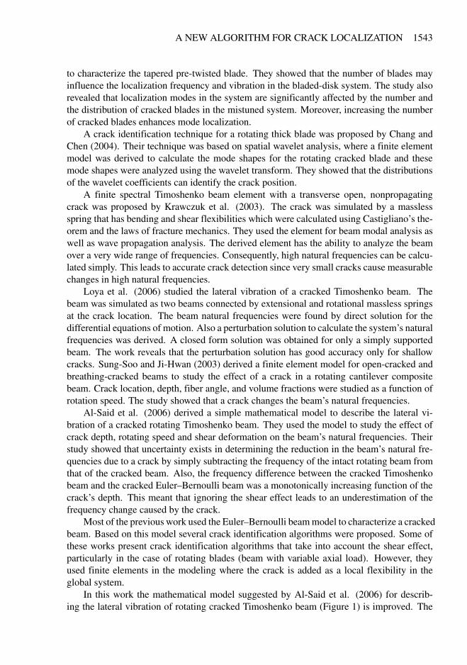
In this work the mathematical model suggested by Al-Said et al. (2006) for describ-ing the lateral vibration of rotating cracked Timoshenko beam (Figure 1) is improved. The
Figure 1. Physical model for the rotating cracked beam.
enhancement is achieved by adding the crack’s effect on the beam’s lateral deformation inaddition to its effect on the beam slope. Also a more accurate function describing the stressintensity factors corresponding to the first and the second modes of crack growth is adopted.The assumed mode method combined with Lagrange’s equation is used to derive the gov-erning equations of motion for the system. Using this method in the derivation reflects thecrack and the rotational speed effects in all system modes. Therefore, these effects globallymanifest their presence throughout the system.
In practice the changes to the system’s dynamical characteristics, which are used to iden-tify cracks, may be measured globally. Therefore, using the aforementioned method to derivethe mathematical model that describes the system’s dynamical behavior will match up withthe actual procedures used to measure the system’s dynamical parameters. The model isverified by means of three-dimensional finite-element model analysis. The general purposefinite-element program ANSYS 8.0 is used. The derived model is used as a basis for a newcrack localization algorithm that utilizes the variation of a single natural frequency versus afew values of rotational speed to identify the location of the crack. The proposed algorithmhas different means of checking/reconfirming its crack estimates. This may be used to im-prove the accuracy of the decision. This is achieved by utilizing different combinations ofrotational speeds and natural frequency variations. The finite-element analysis (FEA) is usedto check the capability and the accuracy of the algorithm in identifying crack location.
NOMENCLATURE
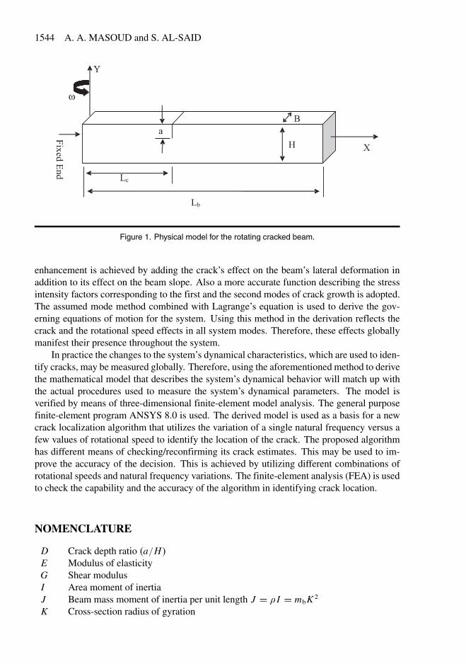
D Crack depth ratio �a�H�E Modulus of elasticityG Shear modulusI Area moment of inertiaJ Beam mass moment of inertia per unit length J � � I � mbK 2
Lb Beam lengthmb Mass per unit length of the beamM Internal beam momentT�U Beam kinetic and potential energy, respectively
t� Reference time, ���AL4
b
E Iy Total beam deflection� Beam cross-sectional angle of distortion due to shear� Cross-section shear factor.� Beam cross-section angel of rotation due to bendingb Dimensionless crack flexibility due to bending moments Dimensionless crack flexibility due to shear force Angular speed
� Dimensionless time, � t
t�
� Dimensionless coordinate, � x
Lb
U1 Inertia parameter, � K 2
L2b
U2 Shear parameter� � �G
E I
U3 Beam depth to length ratio, � H
Lb
fi � qi ith generalized coordinate for total deflection and pure bendingYi � i ith mode shape for total deflection and pure bending� Dimensionless angular speed���c Non-dimensional natural frequency of rotating cracked beam�� Non-dimensional natural frequency of rotating intact beam��c Dimensional natural frequency of rotating cracked beam� Dimensional natural frequency of rotating intact beam0�0 Dimensional natural frequency of non-rotating intact beam�� � Total derivative with respect to
2. MATHEMATICAL MODELING
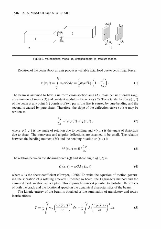
In this section a mathematical model describing the lateral vibration of rotating crackedcantilever Timoshenko beam with a uniform rectangular cross section is developed. Thebeam is assumed to rotate in the horizontal (x–z plane) at a constant angular speed () with asingle sided crack (Figure 1). The cracked beam is simulated using two uniform Timoshenkobeams connected by two massless torsional and translational springs to take into accountthe rotational and translational discontinuities in the beam’s deflection at the crack location(Figure 2a).
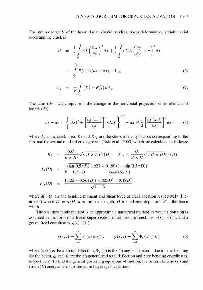
Rotation of the beam about an axis produces variable axial load due to centrifugal force:
P �x� t� �Lb�
x
mb2�d� � 1
2mb
2L2b
�1� x2
L2b
�� (1)
The beam is assumed to have a uniform cross-section area (A), mass per unit length (mb),area moment of inertia (I) and constant modulus of elasticity (E). The total deflection y�x� t�of the beam at any point �x� consists of two parts: the first is caused by pure bending and thesecond is caused by pure shear. Therefore, the slope of the deflection curve �y�x�� may bewritten as
�y
�x� � �x� t�� � �x� t� � (2)
where � �x� t� is the angle of rotation due to bending and ��x� t� is the angle of distortiondue to shear. The transverse and angular deflections are assumed to be small. The relationbetween the bending moment (M) and the bending rotation � �x� t� is
M �x� t� � E I��
�x� (3)
The relation between the shearing force (Q) and shear angle ��x� t� is
Q �x� t� � �G A� �x� t� (4)
where � is the shear coefficient (Cowper, 1966). To write the equation of motion govern-ing the vibration of a rotating cracked Timoshenko beam, the Lagrange’s method and theassumed mode method are adopted. This approach makes it possible to globalize the effectsof both the crack and the rotational speed on the dynamical characteristics of the beam.
The kinetic energy of the beam is obtained as the summation of translatory and rotaryinertia effects:
The strain energy U of the beam due to elastic bending, shear deformation, variable axialforce and the crack is
U � 1
2
Lb�0
E I
���
�x
�2
dx � 1
2
Lb�0
�G A
��y
�x� �
�2
dx
�Lb�
0
P�x� t� �ds � dx���c� (6)
�c � 1
E
�Ac
�K 2
I � K 2I I
�d Ac� (7)
The term �ds � dx�, represents the change in the horizontal projection of an element oflength �ds�:
ds � dx ���dx�2 �
��y �x� t�
�x
2
�dx�21�2
� dx �� 12
��y �x� t�
�x
2
dx (8)
where Ac is the crack area, KI and K I I are the stress intensity factors corresponding to thefirst and the second mode of crack growth (Tada et al., 2000) which are calculated as follows:
KI � 6Mc
B � H2
�H � DFI �D� � KI I � Qc
B � H
�H � DFI I �D�
FI �D� ��
tan�0�5�D�
0�5�D
0�923� 0�199 �1� sin�0�5�D��4
cos�0�5�D�
FI I �D� � 1�122� 0�561D � 0�085D2 � 0�18D3
1� D
where Mc, Qc are the bending moment and shear force at crack location respectively (Fig-ure 2b) where D � a�H , a is the crack depth, H is the beam depth and B is the beamwidth.
The assumed mode method is an approximate numerical method in which a solution isassumed in the form of a linear superposition of admissible functions Y �x�, �x�, and ageneralized coordinates, q�t�, f �t�:
y�x� t� �n�
i�1
Yi �x� qi �t� � ��x� t� �n�
i�1
i �x� fi �t� (9)
where Yi �x� is the ith total deflection, i �x� is the ith angle of rotation due to pure bendingfor the beam, qi and fi are the ith generalized total deflection and pure bending coordinates,respectively. To find the general governing equations of motion, the beam’s kinetic (T) andstrain (U) energies are substituted in Lagrange’s equation:
Using y and � as defined in Equation (9), the kinetic and strain energies (Equations (5) and(6)) may be written as follows:
T � 1
2
Lb�0
mb
n�i�1
n�j�1
qi q j Yi Y j dx � 1
2
Lb�0
Jn�
i�1
n�j�1
fi f j i j dx (11)
U � 1
2
Lb�0
E In�
i�1
n�j�1
fi f j �i
�j dx
� 1
2
Lb�0
�G An�
i�1
n�j�1
�qiY
�i � fi i
� �q j Y
�j � f j j
�dx
�Lb�
0
P�x�n�
i�1
n�j�1
qi q j Y�i Y �
j dx � 48�E IH
L2b
n�i�1
n�j�1
fi f j �i
�j
��xc
� ��2 H2 � BG2
Es
n�i�1
n�j�1
�qi Y
�i � fi i
� �q j Y
�j � f j j
���xc
(12)
where
b �D�
0
DF2I �D�d D� s �
D�0
DF2I I �D�d D� (13)
Substituting Equations (11) and (12) into Lagrange’s equation (10), the coupled equationsdescribing the flexural vibration of a rotating cracked Timoshenko beam are obtained. Theseequations are written in the nondimensional form:
Equation (14) is a system of second-order linear differential equations with constant co-efficients. The solution of this system of equations is a typical eigenvalue problem.
3. THE ASSUMED FUNCTION
To obtain a good approximate solution for the above system, the eigenfunctions of a non-rotating cracked Timoshenko beam are used as the assumed functions. Since the crack hasa localized effect, the beam is treated as two uniform segments connected by torsion andtransverse translational springs at the crack location (Figure 2a). The left segment of thebeam is designated by subscript (1), and the right segment by subscript (2). Assuming thatthe beam is nonrotating and its motion is simple and harmonic, the governing deferentialequations of motion in the nondimensional form are
U2
U1
d4Yi
d� 4 � �2 �1�U2�d2Yi
d� 2 � �2
�U2
U1� �2U1
�Yi � 0� (15)
U2
U1
d4 i
d� 4 � �2 �1�U2�d2 i
d� 2 � �2
�U2
U1� �2U1
� i � 0� (16)
The solutions of these equations are found to be
Yi ��� � C1i cos�� � C2i sin�� � C3i cosh � � � C4i sinh � �� (17)
i ��� � A1i cos�� � A2i sin�� � A3i cosh � � � A4i sinh � �� (18)
In order to find the coefficients of each function Y and as well as the constants � and�, the case of a clamped free beam is considered. The boundary conditions applied to theclamped end are
Y1 �0� � 0� 1 �0� � 0�
At the crack location the compatibility of both moment and shear force are assured by ap-plying the following conditions:
�1
�� c
� � �2
�� c
�� Y �
1
�� c
�� 1
�� c
� � Y �2
�� c
�� 2
�� c
��
At a crack location, the beam’s displacement and slope are discontinuous (Figure 2b). Thisis due to the additional flexibility introduced by the crack. As a result the following displace-ment and slope conditions are held at crack location:
Y1
�� c
�� 2�U2U3s
�Y �
1
�� c
�� 1
�� c
�� � Y2
�� c
��
1�� c�� 2�36U1
U3b
�2�� c� � 2�� c��
Finally, at the free end of the beam, the moment and shear force vanish leading to
�2 �1� � 0� Y �
2�1�� 2�1� � 0�
Substituting Equations (17) and (18) into the above boundary conditions for the cantileverbeam, we obtain eight linear algebraic homogenous equations. These equations may bewritten in a matrix form as
[�]8�8 C�8�1 � 0� �
To calculate the natural frequencies of the nonrotating cracked beam, the determinant of[�] is set to zero. The corresponding coefficient vector C� is calculated. The resultingfrequencies and coefficients are substituted into Equations (17) and (18) to determine themode shapes for total deflection of the cracked beam (Y ���) and the beam’s slope due topure bending ( ���). These functions are substituted into Equation (14) to find the governingequations of motion for a rotating cracked Timoshenko beam.
Since the beam deflection is a simple harmonic motion, the nondimensional differentialequation is represented in the following eigenvalue problem format:�
� �� i�c
�2M�K�s�K
�Qi�c � 0� � (19)
where the elements of matrix �K are the variation of the system stiffness due to the crackonly, and � i
�c is the ith nondimensional natural frequency of the system. The above equa-tion is reduced to represent the lateral vibration of the intact system. By setting the crackflexibilities s and b to zero:�
� �� i�
�2M�K
�Qi� � 0� � (20)
Substitute the mass matrix in Equation (19) by its value obtained from Equation (20), thecrack shear flexibility can be obtained in terms of the intact and cracked system dynamiccharacteristics as
s�D� � �i��� D� ��
�i � �� i�c�
2 � �� i��
2
�� i��
2� Qi
�TKQi
�c
Qi�
T�KQi�c
(21)
where �i is called the ith mode equivalent crack flexibility. From this equation it can be seenthat s is crack depth-dependant only (Equation (13)) and its value is constant for any rotorspeed and system vibrational modes. The steps to predict a crack location are as follows. Asingle mode natural frequency of the intact beam is measured for a few rotational speeds.The same natural frequencies at the same rotational speeds are monitored. If variations arenoticed, a crack may have started to form. The two measured sets of natural frequencies aresubstituted into Equation (21). Plotting the value of �i for a single vibrational mode (e.g.the first mode) at few rotational speeds versus beam span (� ) yields curves that intersect ata single point. This point is the crack location. In practice, the mode frequency values, ��and ��c, are found experimentally with some measuring error. Therefore, �i curves will notintersect at a single point� instead, they will intersect within a small region. To simplify thecrack position search, an ith mode distance function � i (� ) is defined as
� i ��� � 1N
����i��� D��1�� �i�� � D� �N ���
�N�1�j�1
���i �� � D� � j�� �i �� � D� � j�1���� � (22)
Theoretically, this function is equal to zero at the crack location. In practice, this functionhas a minimum value at the crack location.
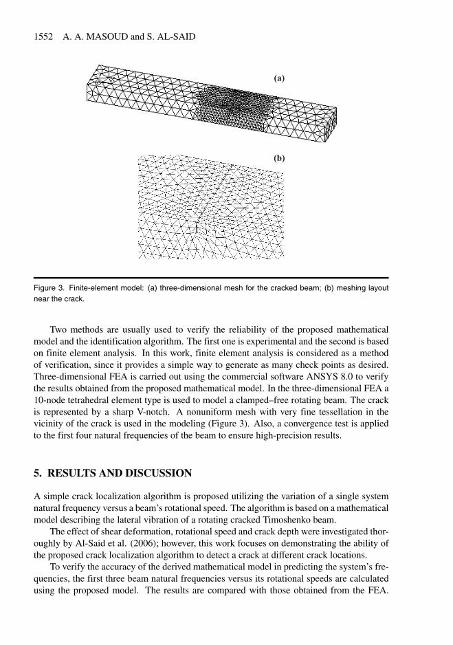
Figure 3. Finite-element model: (a) three-dimensional mesh for the cracked beam� (b) meshing layoutnear the crack.
Two methods are usually used to verify the reliability of the proposed mathematicalmodel and the identification algorithm. The first one is experimental and the second is basedon finite element analysis. In this work, finite element analysis is considered as a methodof verification, since it provides a simple way to generate as many check points as desired.Three-dimensional FEA is carried out using the commercial software ANSYS 8.0 to verifythe results obtained from the proposed mathematical model. In the three-dimensional FEA a10-node tetrahedral element type is used to model a clamped–free rotating beam. The crackis represented by a sharp V-notch. A nonuniform mesh with very fine tessellation in thevicinity of the crack is used in the modeling (Figure 3). Also, a convergence test is appliedto the first four natural frequencies of the beam to ensure high-precision results.
5. RESULTS AND DISCUSSION
A simple crack localization algorithm is proposed utilizing the variation of a single systemnatural frequency versus a beam’s rotational speed. The algorithm is based on a mathematicalmodel describing the lateral vibration of a rotating cracked Timoshenko beam.
The effect of shear deformation, rotational speed and crack depth were investigated thor-oughly by Al-Said et al. (2006)� however, this work focuses on demonstrating the ability ofthe proposed crack localization algorithm to detect a crack at different crack locations.
To verify the accuracy of the derived mathematical model in predicting the system’s fre-quencies, the first three beam natural frequencies versus its rotational speeds are calculatedusing the proposed model. The results are compared with those obtained from the FEA.
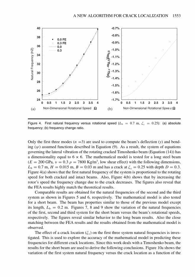
Figure 4. First natural frequency versus rotational speed (Lb � 0�7 m, � c � 0�25): (a) absolutefrequency� (b) frequency change ratio.
Only the first three modes (n �3) are used to compute the beam’s deflection (y) and bend-ing (�) assumed functions described in Equation (9). As a result, the system of equationsgoverning the lateral vibration of the rotating cracked Timoshenko beam (Equation (14)) hasa dimensionality equal to 6 � 6. The mathematical model is tested for a long steel beam(E � 200 GPa, � � 0�3 � � 7800 Kg/m3, low shear effect) with the following dimensions,Lb � 0�7 m, H � 0�015 m, B � 0�03 m and has a crack at � c � 0�25 with depth D � 0�3.Figure 4(a) shows that the first natural frequency of the system is proportional to the rotatingspeed for both cracked and intact beams. Also, Figure 4(b) shows that by increasing therotor’s speed the frequency change due to the crack decreases. The figures also reveal thatthe FEA results highly match the theoretical results.
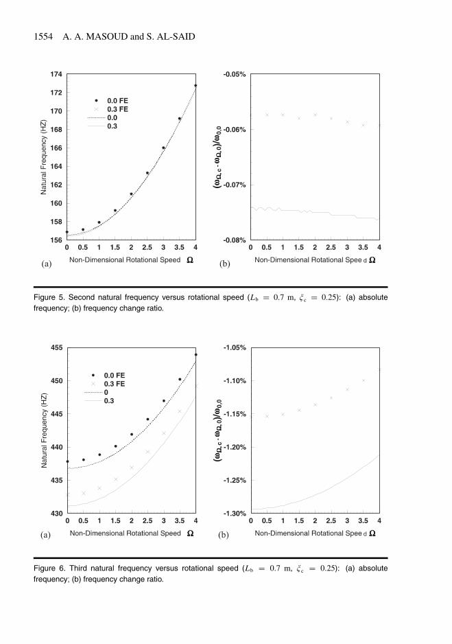
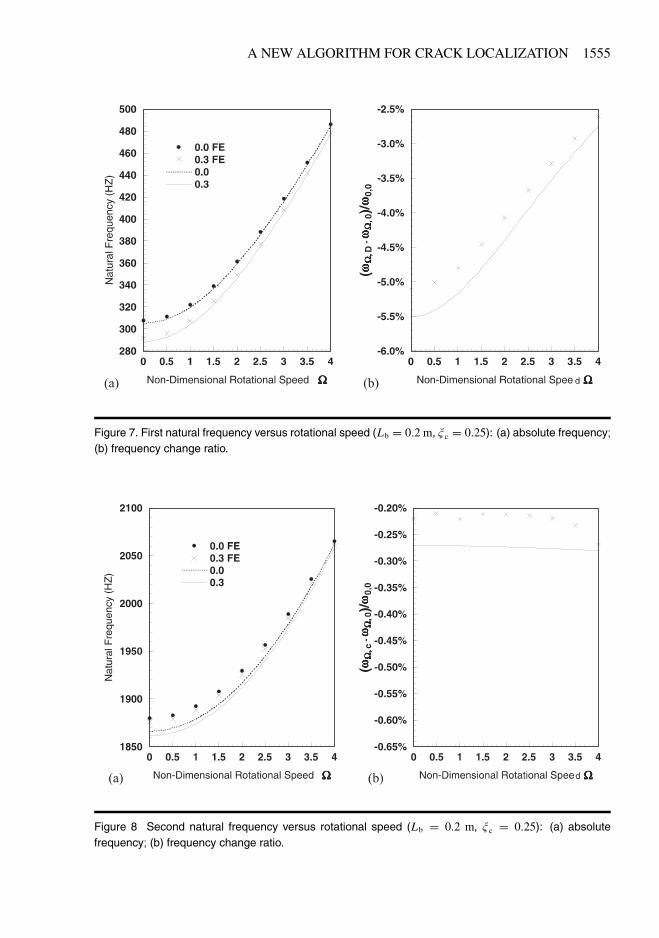
Comparable results are obtained for the natural frequencies of the second and the thirdsystem as shown in Figures 5 and 6, respectively. The mathematical model is also testedfor a short beam. The beam has properties similar to those of the previous model exceptits length, Lb � 0�2 m. Figures 7, 8 and 9 show the variation of the natural frequenciesof the first, second and third system for the short beam versus the beam’s rotational speeds,respectively. The figures reveal similar behavior to the long beam results. Also the closematching between the FEA results and the results obtained from the mathematical model isobserved.
The effect of a crack location (� c) on the first three system natural frequencies is inves-tigated. This is used to explore the accuracy of the mathematical model in predicting thesefrequencies for different crack locations. Since this work deals with a Timoshenko beam, theresults for the short beam are used to derive the following conclusions. Figure 10a shows thevariation of the first system natural frequency versus the crack location as a function of the
Figure 9. Third natural frequency versus rotational speed (Lb � 0�2 m, � c � 0�25): (a) absolutefrequency� (b) frequency change ratio.
Figure 10. First natural frequency versus crack location in terms of rotational speed � (Lb � 0�2 m,D � 0�3): (a) absolute frequency� (b) frequency change ratio.
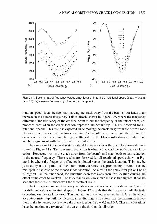
Figure 11. Second natural frequency versus crack location in terms of rotational speed � (Lb � 0�2 m,D � 0�3): (a) absolute frequency� (b) frequency change ratio.
rotation speed. It can be seen that moving the crack away from the beam’s root leads to anincrease in the natural frequency. This is clearly shown in Figure 10b, where the frequencydifference (the frequency of the cracked beam minus the frequency of the intact beam) ap-proaches zero when the crack location approach the beam’s tip. This is observed for allrotational speeds. This result is expected since moving the crack away from the beam’s rootplaces it in a position that has low curvature. As a result the influence and the natural fre-quency of the crack decrease. In Figures 10a and 10b the FEA results show a similar trendand high agreement with their theoretical counterparts.
The variation of the second system natural frequency versus the crack location is demon-strated in Figure 11a. The maximum reduction is observed around the mid-span crack lo-cation. However, moving the crack away from the beam’s mid-span leads to less reductionin the natural frequency. These results are observed for all rotational speeds shown in Fig-ure 11b, where the frequency difference is plotted versus the crack location. This may bejustified by noticing that the maximum beam curvature is approximately located near themid-span in the case of the second mode vibration. As a result the crack strength will be atits highest. On the other hand, the curvature decreases away from this location causing theeffect of the crack to weaken. The FEA results are also shown in these two figures. It can beseen that these results match well the theoretical results.
The third system natural frequency variation versus crack location is shown in Figure 12for different values of rotational speeds. Figure 12 reveals that the frequency will fluctuatedepending on the crack location. This fluctuation is also observed in the FEA results whichaccurately match-up with the theoretical results. Figure 12 shows that the maximum reduc-tions in the frequency occur where the crack is around � c � 0�3 and 0.7. These two locationshave the maximum curvatures in the case of the third mode vibration.
Figure 12. Third natural frequency versus crack location in terms of rotational speed � (Lb � 0�2 m,D � 0�3): (a) absolute frequency� (b) frequency change ratio.
In all of these figures the high matching between the theoretical results and the FEAresults strengthen the confidence in the ability of the derived mathematical model to accu-rately predict the system natural frequencies for a rotating cracked Timoshenko beam. Also,one must keep in mind that the finite-element model (which is used to verify the theoreticalresults) is three-dimensional and the crack is introduced as a sharp v-notch which closelysimulates a real physical crack (Figure 3).
Since the fidelity of the mathematical model is established, it is introduced into thecrack localization algorithm (described in Section 4) to predict the location of a crack. Acrack is introduced into the finite-element model. The frequency reduction due to the crackis calculated for a few values of rotational speeds. The FEA results are used to substitutefor the measured experimental data used by the algorithm to estimate the crack locationplaced in the finite-element model. The advantage of this algorithm compared with theexisting models found in literature is that only one single natural frequency variation needsto be monitored versus a few rotational speeds. Therefore, the first system natural frequencyvariation (between the intact beam and a beam with crack depth D � 0�3) is found forfour rotational speeds namely � � 1� 2� 3� 4. Different combinations of these frequencyvariations are used to evaluate the first mode distance function � 1 (� ) in order to predict thecrack location.
Figure 13a shows the � 1 (� ) function versus the beam span for different crack locationsusing the four values of the rotational speeds � � 1� 2� 3� 4. Figure 13a shows that thedistance function (� 1 (� )) has its minimum at the beam’s span location which lies in thevicinity to the actual crack. An isolated failure to predict the crack’s location is observedfor � c � 0�15. In all remaining cases the distance function provides an accurate predictionof the crack location with a detection estimate very close to the real location. Using three
values of the rotational speeds � � 2� 3� 4, Figure 13b shows that the distance function � 1
(� ) has a clear global minimum. This minimum is used to predict the crack location for allcases. These locations are closer to the real locations than the previous prediction trial (using� � 1� 2� 3� 4).
New prediction trials are shown in Figures 14a and 14b in which only two values ofrotational speeds are used in each figure, namely � � 2� 3 and � � 3� 4, respectively. Inboth figures it can be seen that the distance function has a global minimum very close to thereal crack location. A summary of predicted crack locations is given in Table 1.
Figure 14. First mode distance function � 1 (� ) versus beam span (� ) (D � 0�3): (a) using two rotationalspeeds (� � 2� 3)� (b) using two rotational speeds (� � 3� 4).
6. CONCLUSIONS
A simple crack detection and localization algorithm for a rotating cracked Timoshenko beamhas been proposed. The algorithm is based on a suggested mathematical model for the beam.It utilizes the variation of a single natural frequency due to a crack versus rotation speed todetect the crack location. The mathematical model that describes the lateral vibration of arotating cracked Timoshenko beam has been derived using the assumed mode method andLagrange’s equations. This modeling approach globalizes the effects of the crack and therotational speed. This is the case observed when experimentally measuring the frequencychange due to a crack. The results from the mathematical model have been verified using athree-dimensional FEA. Good agreement has been observed between the theoretical resultsand those obtained from the FEA as well as good accuracy in localizing the crack. The sug-gested algorithm has built-in, multiple means of checking or confirming the crack analysisresults it provides. This is due to the fact that independent analysis of the beam’s health maybe carried-out at different rotational speeds.
The localization algorithm shows promising capabilities in determining the location of acrack with good accuracy. Also, the algorithm has the capability to check/confirm its resultby using different combinations of rotational speeds to calculate frequency variations.
Acknowledgement. The author would like to express his gratitude to College of Engineering Research center in KingSaud University/Kingdom of Saudi Arabia for financial support for this research under grant number No. 427/15.
Al-Said, S. M., Naji M., and Al-Shukry, A. A., 2006, “Flexural vibration of rotating cracked Timoshenko beam,”Journal of Vibration and Control 12(11), 1271–1287.
Chang, C.-C. and Chen, L.-W., 2004, “Damage detection of cracked thick rotating blades by a spatial wavelet basedapproach,” Applied Acoustics 65, 1095–1111.
Chasalevris, A. C. and Papadopoulos, C. A., 2006, “Identification of multiple cracks in beams under bending,”Mechanical Systems and Signal Processing 20, 1631–1673.
Cowper, G. R., 1966, “The shear coefficient in Timoshenko’s beam theory,” Journal of Applied Mechanics Transac-tion of the ASME 33, 335–340.
Dimarogonas, A. D., 1996, “Vibration of cracked structures: a state of the art review,” Engineering Fracture Me-chanics 55(5), 831–857.
Doebling, S. W., Farrar, C. R., and Prime M. B., 1998, “A summary review of vibration-based damage identificationmethods,” The Shock and Vibration Digest 30(2), 91–105.
Fang, X., Tang, J., Jordan, E., and Murphy, K. D., 2006, “Crack induced vibration localization in simplified bladed-disk structures,” Journal of Sound and Vibration 291, 395–418.
Huang, B.-W., 2006, “Effect of number of blades and distribution of cracks on vibration localization in a crackedpre-twisted blade system,” International Journal of Mechanical Sciences 48, 1–10.
Krawczuk, M., Palacz, M., and Ostachowicz, W., 2003, “The dynamic analysis of a cracked Timoshenko beam bythe spectral element method,” Journal of Sound and Vibration 264, 1139–1153.
Kuang, J. H. and Huang, B. W., 1999, “The effect of blade crack on mode localization in rotating bladed disks,”Journal of Sound and Vibration 227(1), 85–103.
Loya, J. A., Rubio, L., and Fernández-Sáez, J., 2006, “Natural frequencies for bending vibrations of Timoshenkocracked beams,” Journal of Sound and Vibration 290, 640–653.
Masoud, S., Jarrah, M. A., and Al-Maamory, M., 1998, “Effect of crack depth on the natural frequency of a pre-stressed fixed beam,” Journal of Sound and Vibration 214, 201–212.
Mei, C., Karpenko, Y., Moody, S., and Allen, D., 2006, “Analytical approach to free and forced vibrations of axiallyloaded cracked Timoshenko beams,” Journal of Sound and Vibration 291, 1041–1060.
Sung-Soo, K. and Ji-Hwan, K., 2003, “Rotating composite beam with a breathing crack,” Composite Structures 60,83–90.
Tada, H., Paris, P. C., and Irwin, G. R., 2000, The Stress Analysis of Cracks Handbook, ASME Press, New York.Wauer, J., 1990, “Cracked rotor dynamics: a state of the art survey,” Applied Mechanics Reviews 43(1), 13–17.