Table of ContentsGeneral Information.............................................................................................................................5
Specification of the AMU2.4-LIA...................................................................................................5Signal Input.............................................................................................................................................5Reference Output....................................................................................................................................5PLL.........................................................................................................................................................5General...................................................................................................................................................6
Licence for the software..................................................................................................................6Get started.............................................................................................................................................6
System requirements........................................................................................................................6Software installation........................................................................................................................6Card and Driver installation............................................................................................................6
Check your APIC configuration..............................................................................................................6Card Installation......................................................................................................................................7Driver Installation ..................................................................................................................................7
Connections to the card...................................................................................................................8APIC configuration..........................................................................................................................8
LockIn Basics.......................................................................................................................................8The general idea of LockIn..............................................................................................................8Mathematical description..............................................................................................................10Noise Measurements......................................................................................................................12Example: Electrical Force Microscope..........................................................................................12The Board......................................................................................................................................14
Software description...........................................................................................................................15Overview........................................................................................................................................15Functions in the Menu Line...........................................................................................................15
Functions in the function line........................................................................................................16Sweep frequency...................................................................................................................................16Sweep bias............................................................................................................................................16
Time constant.......................................................................................................................................17RollOff.................................................................................................................................................18Dynamic...............................................................................................................................................18Coupling...............................................................................................................................................18The Meters............................................................................................................................................18Frequency.............................................................................................................................................19Amplitude.............................................................................................................................................19
Sweep Frequency...........................................................................................................................19Window description..............................................................................................................................19Options for the frequency sweep..........................................................................................................20
Sweep BIAS...................................................................................................................................22Window description..............................................................................................................................22Options for the bias sweep....................................................................................................................23
DLL support........................................................................................................................................24Working with the DLL in C++ projects.........................................................................................24DLL-Functions...............................................................................................................................25Example programs.........................................................................................................................26
LabView Driver and Support..............................................................................................................27Files and Locations...............................................................................................................................27Surface and basic description................................................................................................................27
Programming directions in LabView.............................................................................................28Revision History.................................................................................................................................30
Manual-related Revisions..............................................................................................................30Till 19th June 2007...............................................................................................................................3010th April 2008...................................................................................................................................3010th Frebruary 2009............................................................................................................................30
Hardware Revisions.......................................................................................................................311st November 2006 – Rev 2.2 to Rev 2.3............................................................................................311st December 2006 – Rev 2.3 to Rev 2.3a...........................................................................................3114th April 2007 – Rev. 2.3a to Rev 2.4...............................................................................................3110th April 2008 – Rev 2.4....................................................................................................................31
Software Revisions........................................................................................................................3110th April 2008 – Version 1.02............................................................................................................3111th May 2009 – Version 1.04............................................................................................................3211th July 2009 – Version 1.05..............................................................................................................32
Copyright 2002-2009 Anfatec Instruments AG. All rights reserved. Anfatec, and AMU are trademarks of Anfatec. Other product and brand names may be trademarks or registered trademarks of their respective owners.Anfatec Instruments AG assumes no responsibility for any damage or loss resulting from use of this manual. Anfatec Instruments AG assumes no responsibility for any damage or loss resulting from use of the software. Anfatec Instruments AG assumes no responsibility for any damage or loss by deletion of data as a result of malfunction, dead battery, or repairs. Be sure to make backup copies of all important data on other media to protect against data loss.Important: Please read Anfatec Licence Agreement contained in this handbook before using the accompanying software programs. Using any part of the software indicates that you accept the terms of Anfatec Software Licence Agreement.
Page 3 (32)
GENERAL INFORMATIONSPECIFICATION OF THE AMU2.4-LIAGeneral
Digital Quad(1)-Phase Lock-In AmplifierDynamic Reserve > 135 dB (1)
Noise < 6 nVrms/Hz0.5 @100kHz (1)
Time Constants 0.1 ms ... 1 ks (1)
Sensitivity 10 nV ... 10 VPhase Resolution 0.001°
SIGNAL INPUT
Voltage Input single-ended SMBInput coupling: dc or ac (f3dB = 2 Hz)Input Impedance 100 kΩ || 20 pF (1) / 1 MΩ on requ.Damage Threshold +/- 12 V Bandwidth dc to 1 MHz (f3dB > 1 MHz)Input Ranges ± 5 V, ± 500 mV, ± 50 mV (1)
RollOff 6 dB/oct, 12 dB/oct, 24 dB/octTime Constants 0,2 ms ... 5 sGain deviations between dynamic ranges: < 5%
REFERENCE OUTPUT
Internal Oscillator 10 mHz .. > 1 MHzFrequency Resolution < 10 mHzFrequency Accuracy +/- 50 ppm from 0 °C to 70 °CReference Output Voltage < 1 mVpp ... 15 VppOutput Noise Uac = 1 mV
@ 100 kHz < 200 nVrms/Hz0.5
PLLFrequency range 1 Hz .. 1 MHzLocking time < (100 ms+ 10 Cycle)Phase error < 4 deg @ f < 1 kHz Input amplitude TTL
(1) See Revision History on Page 27
Page 4 (32)
GENERAL
Interface Plug & Play PCI-Bus 2.4 interface Drivers Windows NT/2000, Windows XPInterrupt rate 40 kHzWarranty 2 years
LICENCE FOR THE SOFTWARE
The LockIn software is provided with the General Public Licence (GPL). This licence has been developed within a project of the "Free Software Foundation". It gives the user the liberty, to add changes in the code and the programmer the security, not to get in trouble due to the users changes.Most commercial software packages don't use this licence, because they want to keep the right to sell the newer version later as update. An open software can be changed by the user. So, he can adapt the software to his problem. Free software, has to stay free, even if the user add some changes. Therefore, GPL protects the software so, that all programs which are based on a GPL protected source code has to provided with the same GPL again. The licence also hinders software patenting.
GET STARTEDSYSTEM REQUIREMENTS
– compatible PC – free PCI slot– APIC installed (recommended) - for details see here– 1 MB hard disk space– Windows NT 4.0 / Windows 2000 or Windows XP
SOFTWARE INSTALLATION
There are two ways for installation:automatic. Start the setup.exe in the root directory of the installation CD.
Manual: Before installing the driver, install the software. Put the installation disk named “Software for the AMU2.4” in the disk drive and and copy at least the four needed fileslockin.exe, lockin.ini, lockin.sys and lockin.infinto a new directory, for instance: C:\Programme\Anfatec\LockIn . On the installation CD, you find these files under the directories: /bin (*.exe, *.ini) and /driver (*.sys, *.inf).If you later want to use the source code, you find it in the directory /sources. Please contact us for newer versions.
CARD AND DRIVER INSTALLATION
CHECK YOUR APIC CONFIGURATION
The APIC improves the interrupt control in your system. The APIC will dramatically increase the performance of the PC. It is installed together with the Power Manager while Windows installation. Check it as follows:
• Windows 2000Open “Einstellungen / Systemsteuerung / System / Hardware” (“Configuration / System control / System / Hardware”) and start the “Geräte Manager” (“Device Manager”). It appears a list of devices. The information about the APIC is in the submenu “Computer”.
• Windows XPOpen “Systemsteuerung / System / Hardware” (“System control / System / Hardware”) and start the “Geräte Manager” (“Device Manager”). It appears a list of devices. The information about the APIC is in the submenu “Computer”.
The APIC is installed, if the “ACPI-Uniprocessor-PC” is shown in “Computer”. If only “Standard PC” is found there, even the changes of the BIOS will not help, to make Windows use the APIC. If you find the entry “Standard PC”, you can follow the instructions in the APIC configuration.
CARD INSTALLATION
Switch off the PC. Remove the power completely, because PC's keep the supply voltages at the PCI slots on, if the PC is only shut down.Plug the card in one of the PCI-slots of your PC and switch on again. Start the setup.exe on the CD. All related files are copied to the related directories.
DRIVER INSTALLATION • Windows 2000/ Windows XP
While Windows boots, it finds new hardware. Log in as administrator. WindowsTM will mention, that it has found new hardware on your computer. If the software is not yet on your computer, you can copy the recommended files now to your hard disk.Check the second point, which means “Treiber aus einer Liste auswählen”. Say OK and give the path to the “lockin.inf” (for instance: C:\Programme\Anfatec\LockIn\Driver) with the button “Durchsuchen” (“Search”). Check the driver “LockIn Interface” and finish with “Fertigstellen” (“Finish””).
• Later re-installation of a driver
Log in as administrator and call in the “System control” the topic "system". Chose the card “hardware“ and open the “device manager”. It shows all hardware components installed on your PC. With a double click on the "Anfatec Measurement Unit", the submenu "Anfatec Measurement Unit" or “Anfatec LockIn” is opened. A second double click opens a window, which shows the properties of the device.
Select the card “Driver” and start the button “Driver actualisation”. A dialogue is opened, which asks: “Do you want to actualise the driver?”. In the next window please check the second option “Search for a suitable driver” and click “OK”. At the question, where the driver is, the right path has to be given as “other sources”. It is the path, where the new *.inf file is located. Eventually, you have to select again the right device from a list of possible devices. Check the Anfatec Measurement Unit again and say “OK” and “Finish”. The PC has to be rebooted in order to activate the new driver.
Connect the reference output to the excitation input of your experiment. The signal input has to be connected to the signal to be analysed.The microscope control is used for the external D/A- and A/D-channels, which can be updated any time.
APIC CONFIGURATION
Attention: this change is critical for your system. It can cause that your computer refuses to boot. Only administrators should perform this action.
The way to switch on the APIC later, if the system has been installed as “Standard PC” without Power Management, is described in detail in the computer magazine C't 19/03 on page 190/191 in German. It works as follows:
Double click on the “Standard PC” icon and say “actualise driver” (Treiber aktualisieren). Check the second line: “Show all known drivers”. Say OK and check again, that all known hardware components for this device class are shown (“Alle Hardwarekomponenten dieser Geräteklasse anzeigen.”. It appears a list on the right sight, which shows “standard PC”, “ACPI-Uniprocessor-PC” and others. Select now the “ACPI-Uniprocessor-PC” and say OK. Because this change can cause a real damage on your system, the computer will ask you “Do you really want to exchange this driver?”. Say “Yes” and complete with “finish”.
When the computer restarts, you have to go into the BIOS setup now! Press “Entf” or “Del” button on your keyboard during system reboot. In the BIOS, switch on the ACPI mode with “ACPI Aware O/S = Yes” under the Power Management menu. For most BIOS types, this is only one point to change. But for some BIOS, the APIC, which is part of the ACPI, has to be switched on separately. Therefore, check your BIOS settings careful, that the APIC is really switched on.
If the computer does not reboot alone now, you have to reset and to repair your system from the Windows Installation CD.Remark: Wrong BIOS settings can cause, that Windows refuses to repair the system from CD. It will stop with “could not find ntkrnlmp.exe – error code 7” for instance.
LOCKIN BASICSTHE GENERAL IDEA OF LOCKIN
A LockIn amplifier is a phase sensitive bandpass filter with a centre frequency f and a bandwidth t. It has two output signals in parallel: either the amplitude R and the phase j, or the real part X and the imaginary part Y.• The centre frequency is the frequency at which the LockIn is searching for its signal. • The bandwidth gives the frequency range around this centre frequency, from which the output
Page 7 (32)
Figure 1: Connections to the LockIn card.
signal is derived. • The output signal R is the measured amplitude of the analysed signal at the centre frequency f.• The phase j is the relative phase shift between the analysed signal and an internal reference
signal with the same frequency.For analysing the input signal, the LockIn needs an internal frequency reference with a certain amplitude and phase. (see Fig. 7).
The bandwidth of a LockIn can be visualised by a simple setup. A generator gives a constant frequency fin signal to the input and sweeping the centre frequency f around the input frequency f in. Figure 8 shows that the amplitude at the input frequency is always measured with the same value. For other frequencies, the measured amplitude is dependent on the distance between the actual centre frequency and the input signal frequency.
A schematic diagram with the basic components of the lock-in amplifier is shown in Figure 1 on page 7. First of all the received signal is amplified and digitized. Divided into two separate channels, the signal is multiplied by the mentioned reference signal (with frequency ωref) and the 90° phase-shifted reference signal respectively. The reference signal is generated with the lock-in's digital oscillator. An additional implemented phase displacement Ψ enables to compensate phase differences caused by the measuring equipment. After multiplication, the resulting signals are low-pass filtered and provide now information about the real part X and the imaginary part Y of the analyzed signal relating to the phase position of the reference signal. Out of them the amplitude R as well as the relative phase shift φ are calculated.
Page 8 (32)
Figure 2: Schematic diagram with the basic components of the lock-in amplifier.
MATHEMATICAL DESCRIPTION
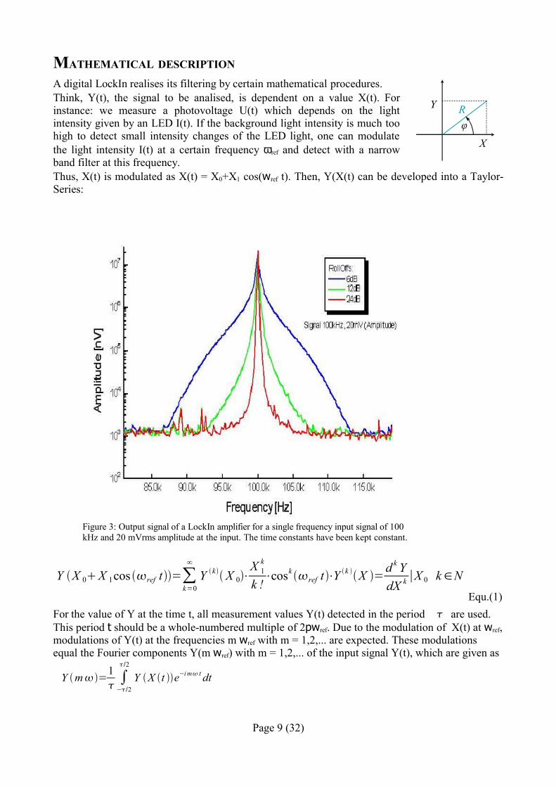
A digital LockIn realises its filtering by certain mathematical procedures. Think, Y(t), the signal to be analised, is dependent on a value X(t). For instance: we measure a photovoltage U(t) which depends on the light intensity given by an LED I(t). If the background light intensity is much too high to detect small intensity changes of the LED light, one can modulate the light intensity I(t) at a certain frequency ωref and detect with a narrow band filter at this frequency.Thus, X(t) is modulated as X(t) = X0+X1 cos(wref t). Then, Y(X(t) can be developed into a Taylor-Series:
Equ.(1)For the value of Y at the time t, all measurement values Y(t) detected in the period are used. This period t should be a whole-numbered multiple of 2pwref. Due to the modulation of X(t) at wref, modulations of Y(t) at the frequencies m wref with m = 1,2,... are expected. These modulations equal the Fourier components Y(m wref) with m = 1,2,... of the input signal Y(t), which are given as
Y m=1 ∫−/2
/2
Y X t e−i m t dt
Page 9 (32)
Y X 0X 1cos ref t =∑k=0
∞
Y k X 0⋅X 1
k
k !⋅cosk ref t ⋅Y k X =
d k YdX k ∣X 0 k∈N
X
Y Rφ
Figure 3: Output signal of a LockIn amplifier for a single frequency input signal of 100 kHz and 20 mVrms amplitude at the input. The time constants have been kept constant.
and together with Equ. 1
Y mref=∑k=0
∞
Y k X 0X 1
k
k!Km
k
with
Kmk =
1 ∫
−/2
/2
cosk ref t e−i m ref t dt .
The factors Kmk get zero for k to infinity. For small k, the Km
k remain too big to be neglected. In order to neglect n-th order parts, the n-th derivative of Y(t) to X(t) has to be negligible.The first 10 (k = 1 ... 10) coefficients Km
k for the first 4 harmonics m = 1 ... 4 are given in the following table:
k =m 1 2 3 4 5 6 7 8 9 10
112
38
516
35128
63256
214
14
1564
732
105512
318
532
21128
21128
41
163
327
6415
128
NOISE MEASUREMENTS
Lock-in amplifiers are capable to measure noise. They detect a signal at a certain center frequency ωref with a equivalent noise bandwidth. For a Gaussian noise, the equivalent noise bandwidth of a real low pass filter is the bandwidth which passes the same amount of noise as a perfect rectangular filter with the equivalent noise band width.
The equivalent noise bandwidth of the eLockIn is determined by the time constant and the slope of the used Butterworth filter. It is calculated by
Bn=∫0
∞ 112n d . (4)
The normalized Butterworth filter noise bandwidths are:
Filter order Bandwidth / τ1 1,5707962 1,110721
Page 10 (32)
Filter order Bandwidth / τ4 1,026172
In order to measure noise spectra, the resulting data should be divided by the square-root of the used bandwidth.
The integrated spectrum is taken with a time constant of 10 ms and a slope of 24 dB (4th order) – bandwidth factor ~ 1,03. The related bandwidth is then 1/10 ms = 100 Hz. In order to interpret the result as noise in units of V/Hz0.5, the spectrum should be divided by 10 Hz0.5(= sqrt(100 Hz)).
EXAMPLE: ELECTRICAL FORCE MICROSCOPE
In this chapter electrical force microscopy (EFM) is briefly presented as an example for the application of lock-in amplifiers.EFM is a related technique to the well-established atomic force microscopy (AFM). Its special aim is to detect electrical forces to learn something about the electrical properties of a surface, for example about the local distribution of surface potentials on electronic devices or different dopant concentrations in semiconducting materials.
The fundamental experimental setup shown in Figure 4 is based on a conventional atomic force microscope: In the non-destructive dynamic non-contact mode, an oscillating metallic tip fixed to a cantilever is scanning over the surface by means of a piezo scanning device. The distance between
Page 11 (32)
Figure 4: Schematic diagram of the EFM experimental setup.
Lock-In 1 Feedback
Laser
2nd harmonic
1st harmonicLock-In 22ωref
ωref
Ubias~
Uac cos(ωref t)
+
zyx
ωr
ωref
Sample
Photo-detector
Tip
Lock-In 3
tip and sample can be controlled by monitoring the oscillation amplitude of the cantilever, because its value is influenced by short-range van der Waals forces. Therefore a reflected laser beam and a position-sensitive photo-detector are used. A lock-in amplifier analyzes the detector signal at the cantilever resonance frequency ωr and passes the determined amplitude value to a feedback control system that re-adjusts the tip-sample distance. The required displacement of the z-piezo can be recorded as topography signal.In addition to the topography, EFM detects electrical forces, too. These forces are proportional to the derivative of the capacitance C of the tip-sample arrangement with respect to the tip-sample distance z and proportional to the potential difference U squared:
Fel =−12
d Cd z
U2 . (5)
A possible voltage dependency of C is neglected in this consideration.The voltage U contains a direct voltage part UDC and an alternating voltage part UAC:
U = U DC U AC⋅cosref t . (6)UDC consists of an additional applied bias voltage and, what is especially interesting from the physical point of view, potential differences caused by different electronic work functions and charges. For separating the impact of these electrical forces from other forces (e.g. van der Waals forces), U has to be modulated at the frequency ωref. As a result of this, the measurable photo-detector signal is modulated, too.Inserting equation (6) in (5) and using power-reduction formulae of trigonometric functions one can expect a force between tip and sample at the frequency ωref as well as at 2·ωref. Figure 5 confirms this prediction: It shows the frequency spectrum of the cantilever oscillation with clear signals at the mechanical excitation frequency ωr and at the frequencies of the first and second harmonic of the electrical excitation.
Now two additional lock-in amplifiers (see Figure 4) can be used to analyze the photo-detector signal at the frequency ωref and 2·ωref
simultaneously. The measured amplitudes of the signals are proportional to the strength of the electrical forces.
Page 12 (32)
Figure 5: Frequency spectrum of the oscillating cantilever
10 20 30 40 50
1E-5
1E-4
1E-3
0.01
Am
plitu
de [V
]
Frequency [kHz]
ωr
ωref2·ωref
THE BOARD
Figure 6 shows, how analogue and digital parts are ordered on the board. The output gains are switched without any notice to the user in dependence on the used output amplitude. The input gains in the input amplification chain are the “dynamic”, which is selected in the program. They can be switched between 1, 10 and 100.
SOFTWARE DESCRIPTIONOVERVIEW
Figure 7 shows the main window of the LockIn program, which appears when the program is opened. For checking the actually detected values, the two meters are used. Basic input parameters (frequency, amplitude, offset phase and harmonic) can be selected in the right part of the window. Parameters, which concern the input stage (time constants, RollOff, and input gain) are chosen in the left part of the window.
The frequency is either the internal frequency (black numbers) or the detected external frequency
Page 13 (32)
Figure 7: Main window of the LockIn program with description of the functions.
Figure 6: Photograph of the LockIn board and description of the location of the single parts.
from the reference input (grey numbers).
The menu line allows typical Windows functions, while the button in the function line open new windows with specific functions.
FUNCTIONS IN THE MENU LINE
FILE
Exit - Exit the program
OPTION
• overload
Overload occurs, when the dc input signal exceeds the full scale sensitivity for the selected range. This full scale sensitivity is 7 Vrms for high reserve, 700 mVrms for normal reserve and 70 mVrms for low reserve. With this option can be selected whether a beep and/or a color change is shown in case of overload.
• ext. reference
For LockIn-amplifier versions with PLL (Phase locked loop), the reference frequency can be either the internal oscillator frequency or an external reference frequency. If the “ext. reference” is selected, the internal PLL is enabled. The locked frequency is shown in grey in the frequency window. If there is no input signal connected to the reference input, a default frequency of 2 mHz is shown, but the LockIn is not working properly.With disabled PLL, the frequency given in the frequency window is written in black.
VIEW
It can be selected, which of the meters is shown.
HELP
About – shows the current program version.LockIn help – calls the table of contents of the HTML help file supplied with the programHelp as PDF – calls the current manual (AMU24_Manual.pdf) and opens it in the Microsoft Internet Explorer.
FUNCTIONS IN THE FUNCTION LINE
SWEEP FREQUENCY
Opens the "frequency sweep" window
SWEEP BIAS
Opens the "bias sweep" window
Page 14 (32)
OSCILLOSCOPE
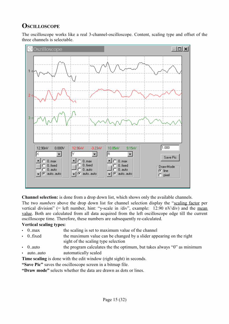
The oscilloscope works like a real 3-channel-oscilloscope. Content, scaling type and offset of the three channels is selectable.
Channel selection: is done from a drop down list, which shows only the available channels.The two numbers above the drop down list for channel selection display the “scaling factor per vertical division” (= left number, hint: “y-scale in /div”, example: 12.90 nV/div) and the mean value. Both are calculated from all data acquired from the left oscilloscope edge till the current oscilloscope time. Therefore, these numbers are subsequently re-calculated.Vertical scaling types:• 0..max the scaling is set to maximum value of the channel• 0..fixed the maximum value can be changed by a slider appearing on the right
sight of the scaling type selection• 0..auto the program calculates the the optimum, but takes always “0” as minimum• auto..auto automatically scaledTime scaling is done with the edit window (right sight) in seconds.“Save Pic” saves the oscilloscope screen in a bitmap file. “Draw mode” selects whether the data are drawn as dots or lines.
Page 15 (32)
PARAMETER SETTINGS
TIME CONSTANT
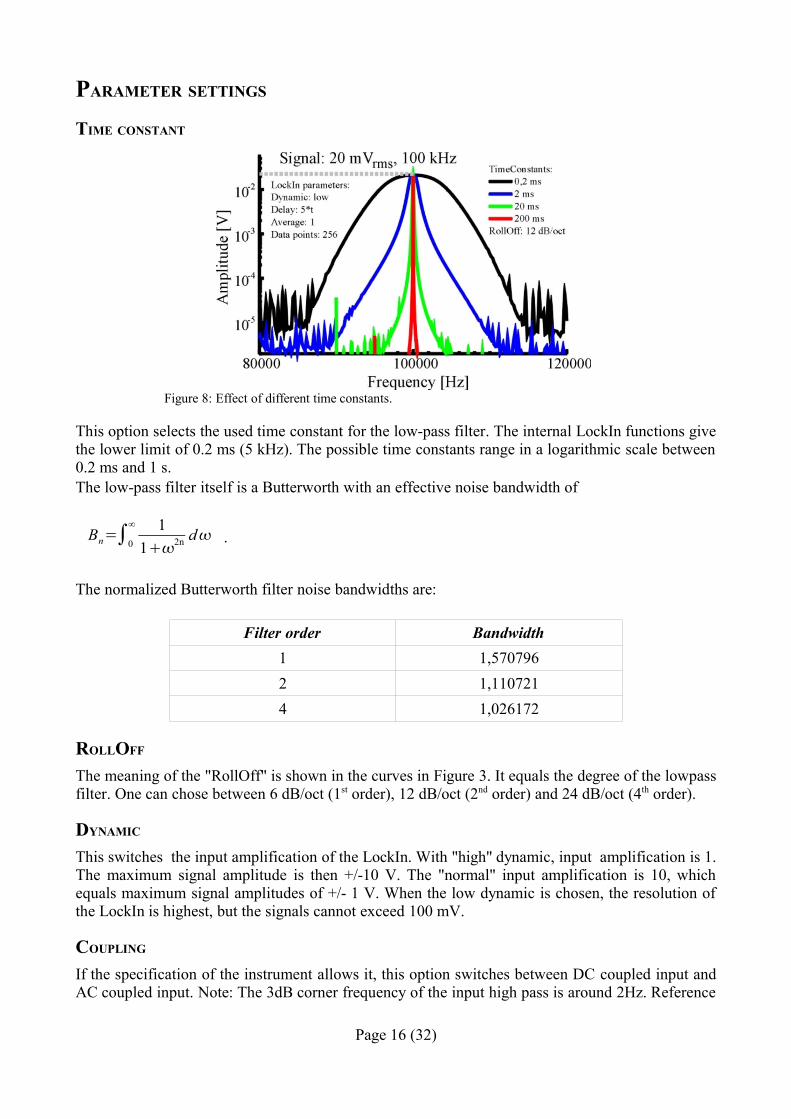
This option selects the used time constant for the low-pass filter. The internal LockIn functions give the lower limit of 0.2 ms (5 kHz). The possible time constants range in a logarithmic scale between 0.2 ms and 1 s. The low-pass filter itself is a Butterworth with an effective noise bandwidth of
Bn=∫0
∞ 112n d .
The normalized Butterworth filter noise bandwidths are:
Filter order Bandwidth1 1,5707962 1,1107214 1,026172
ROLLOFF
The meaning of the "RollOff" is shown in the curves in Figure 3. It equals the degree of the lowpass filter. One can chose between 6 dB/oct (1st order), 12 dB/oct (2nd order) and 24 dB/oct (4th order).
DYNAMIC
This switches the input amplification of the LockIn. With "high" dynamic, input amplification is 1. The maximum signal amplitude is then +/-10 V. The "normal" input amplification is 10, which equals maximum signal amplitudes of +/- 1 V. When the low dynamic is chosen, the resolution of the LockIn is highest, but the signals cannot exceed 100 mV.
COUPLING
If the specification of the instrument allows it, this option switches between DC coupled input and AC coupled input. Note: The 3dB corner frequency of the input high pass is around 2Hz. Reference
Page 16 (32)
Figure 8: Effect of different time constants.
frequencies around 2 Hz and below may cause misleading results.
THE METERS
The meters display the LockIn output channels, which are X and Y as well R and Phi, in physical units.
FREQUENCY
If written in black letters, this is the actual reference frequency which is used at the reference output and as reference frequency for the signal evaluation of the input. Click with the right mouse button to switch from external to internal reference. In case of internal reference, the numbers are written in grey.
AMPLITUDE
This is the amplitude of reference output.
PHASE
Allows to give a phase offset between the reference output and the input. In the schematic in Fig. 2, this phase is equal to the LockIn input parameter “Phase γ”.
HARMONIC
Selects, which harmonic of the reference frequency is evaluated. The possible values range from 1 to 9. When selecting higher harmonics, take care, that, due to lowpass filtering, the maximum input frequency the LockIn cannot be higher than 2 MHz.
SWEEP FREQUENCY
This window serves the acquisition of frequency dependent spectra of any of the LockIn input channels. The frequency sweep uses the internal reference. When the PLL is enabled for normal operation, it will be disabled during frequency sweep.The number of data points, parameters for the visualisation as well as for the saving and copying the acquired data can be changed in the option window.
WINDOW DESCRIPTION
“Delay”: is the time delay between each acquired data point. During spectrum acquisition, the frequency is set to the next value. Then, the system waits “Delay” and takes one single value from the acquired Channel.As this delay has to be related to the time constant of the LockIn, the options in the drop down list for the delay are given in multiples of τ. Thus, independently on the time constant τ given in the main window, the time constant for the acquisition of the spectrum is always correct. “from” and “to” define the values of the start frequency and the stop frequency. For the spectrum's acquisition, one chooses the wanted frequency range, and presses the “start-button”. If the time constant was very high, the spectrum might take a while. In order to stop the acquisition, the start-button can be pressed a second time.“Channel” is a drop down list of available data channels (X, Y, R, and Phi).“Range back” - click with the right mouse button in the data screen, and a pop-up menu with list of four frequency ranges appears. The upper one is a standard range, which can be changed in the “Option/acquire” part. The next three are, from the bottom to the top, the last three used frequency ranges.
Page 17 (32)
OPTIONS FOR THE FREQUENCY SWEEP
The option window provides three cards: “save” - parameters about the saving and copying format of data, “acquire” – parameters about the data acquisition, and “view” – parameters around the screen of showing the data.
The saved files and the data copied to the clipboard have an ASCII structure. The data are written in lines (each frequency value one line) and delimited by the given delimiter (“TAB” in the example) are saved. The frequency values are only saved, if “Save x-Axis” is checked. All history data are saved too and also delimited the same character.
Data file example:
1000,00 234,091200,00 237,98 ...
Page 18 (32)
Figure 9: Window for the spectra acquisition.
“Wobbel” - if a large range is scanned for overview purposes and the frequency peak, which should be found, is too small to be excited (because the single frequency steps are too big), the wobble option can help. If wobble is checked, the frequency is not kept constant during scan. It is varied (wobbled) between the neighboured values while the data are taken. This makes sure, that even small peaks can be found in an overview spectrum with only some 100 data points.
“Standard frequency” - is the range, which appears at the topmost position, if the right mouse button is used in the data screen of the “Sweep Frequency” window.
In the data screen, several data curves can be displayed simultaneously.
Therein, the “History depth" is the number of old curves added to the actual one. If the depth is 2, the actual, the last and the last but one curves are displayed. The actual curve is always of black colour. The last is red, and the last but one is green. More curves get the usual next colours from the WindowsTM palette.It can be chosen between pixel and vector drawing of data.
Page 19 (32)
Figure 10: description of the card "save" in the sweep frequency options.
Figure 11: Description of the card "acquire" of the sweep frequency options.
SWEEP BIASWINDOW DESCRIPTION
This window serves the acquisition of voltage dependent spectra of any of the LockIn input channels. Usually, the time constant has to be related to the time constant of the LockIn.The number of data points, parameters for the visualisation as well as for the saving and copying the acquired data can be changed in the option window.
Page 20 (32)
Figure 13: Window for the spectra acquisition.
Figure 12: View options for the frequency sweep.
OPTIONS FOR THE BIAS SWEEP
The option window provides, in analogy to the option window of the frequency sweep, three cards: “save” - parameters about the saving and copying format of data, “acquire” – parameters about the data acquisition, and “view” – parameters around the screen of showing the data.
The saved files and the data copied to the clipboard have an ASCII structure. The data are written in lines (each frequency value one line) and delimited by the given delimiter (“TAB” in the example) are saved. The voltage values are only saved, if “Save x-Axis” is checked. All history data are saved too and also delimited by the same character.
Therein, the “History depth" is the number of old curves added to the actual one. If the depth is 2, the actual, the last and the last but one curves are displayed. The actual curve is always of black colour. The last is red, and the last but one is green. More curves get the usual next colours from the WindowsTM palette.
The card “View” is almost equal to the card “View” of the sweep frequency options window.
Page 21 (32)
Figure 14: description of the card "save" in the sweep bias options.
Figure 15: Description of the card "acquire" of the sweep frequency options
DLL SUPPORT
The AMU2.x boards can be addressed from other programs and LabViewTM by calling functions provided in a DLL. In order to make the use of these functions as transparent as possible, the following files are provided:
– source code of the DLL written in Delphi 6.0 (./DLL/Lockin.dpr)– example in Borland C++ Builder 5.0 for using the DLL (./DLL/cpp/Project1.bpr)– example in Delphi 6.0 fro using the DLL (./DLL/Delphi/Demo.dpr)– current version of the DLL (<WINDIR>/Lockin.dll)
This DLL is compatible with C calling conventions. The convention of the functions in C++ need an underline in front of function names.
The 'lockin.dll' (and 'lockin.ini' for older versions) have to be located in 'C:\Windows' .
WORKING WITH THE DLL IN C++ PROJECTS
Add the lib-file genarated from the DLL to the project in Borland C++ Builder 5.0 by opening 'Project / Add to Project' (see figure).Chose the lockin.lib as the file to be added.
If the lockin.lib does not exist, it can be created from the command line:– open the command prompt by
running 'cmd' in 'Start/Run..' under the Windows Start Menu.
– Go to the directory in which the lockin.dll is located (e.g. 'C:\Windows' )– type: 'implib lockin lockin.dll'
The lockin.lib is created in the same directory based on the lockin.dll.
To call functions residing in the DLL, headers are necessary, so add 'import.cpp' also to the project, which contains:
double _declspec(dllimport) cdecl SetLockInPhase (double Phase);long _declspec(dllimport) cdecl SetLockInHarm (long Harm);long _declspec(dllimport) cdecl SetLockInPllOn (long PllOn);long _declspec(dllimport) cdecl SetLockInTimeConst (long Time);long _declspec(dllimport) cdecl SetLockInRollOff (long Time);double _declspec(dllimport) cdecl GetLockInChannel (long Channel);long _declspec(dllimport) cdecl SetLockInHardGain (long Gain);long _declspec(dllimport) cdecl GetLockInStatus;long _declspec(dllimport) cdecl SetLockInCoupling (long Coupling);All these functions give the set value back when they are called, except 'SetLockInAmpl'. 'SetLockInFreq' gives the set value back, when the system uses the internal oscillator (PLL = Off) or allows the user to read the external frequency, when then PLL is ON.
DLL-FUNCTIONSSetLockInFreqthis function sets the center frequency of the lockin to a value in Hz and returns the value of the frequency in Hz. If the PLL is OFF, the return value equals the sent value. If the PLL is ON, this function can be used to read the external frequency value.
SetLockInAmplsets the output amplitude of the reference output in V and gives no value back.
SetLockInPhasesets the phase offset in degree and returns this phase offset in degree.
SetLockInHarmsets the harmonic at which the signal is analysed. The harmonic can vary between 1 and 15. It returns the harmonic value.
SetLockInPllOnswitches the PLL on (1) or off (0) and gives the state of the PLL back. The state 1 stands for “PLL ON”, while the state 0 stand for “PLL OFF”. When using the external trigger, please make sure, that later calls of SetLockInHarm(H) or SetLockInPhase do not reset the state of the PLL to zero.Starting from software package Version 1.05, the functions “SetLockInPhase,”, “SetLockInHarm”, “SetLockInFreq” and “SetLockInAmpl” do not overwrite the PLL setting anymore.
SetLockInTimeConstsets the time constant for the low pass filter0 0.25 ms1 0.5 ms2 1 ms3 2 ms4 5 ms....13 5 s
SetLockInRollOffsets the RollOff for the low pass filter:
Page 23 (32)
0 6 dB/oct1 12 dB/oct2 24 dB/oct
GetLockInChannelreads the results in the channel number x, where x is:0 real part = X1 imaginary part = Y2 amplitude = R3 phase = phiIt gives the the read value of this channel in V back.
SetLockInHardGainSwitches the input gain of the lockin between1 high reserve10 normal100 low noise
SetLockInCouplingSwitches the input coupling of the lockin between ac mode and dc mode1 ac coupling0 dc coupling
GetLockInStatusReturn bit = 1 if the input of the lockin is overloaded
When the DLL is initialized, it sets the following default values:Phase 0 degreeHarmonic: 1PLL.: offTime constant: 1 msRollOff: 12 dBInput Gain: 1 (high reserve)
EXAMPLE PROGRAMS
There are two program examples provided, one in Borland Delphi 6.0 (demo.exe) and one in Borland C++ Builder 5.0. They use both the function name conventions compatible with C++.
In newer hardware versions, the scaling parameter are stored on the card. When the DLL is used for the first time, these parameters are transferred to the Windows Registry.
If the card does not contain the parameters (older versions), the DLL searches for the file 'lockin.ini' and transfers the parameters to the Windows Registry. Later, the DLL just uses the entries in the Registry.
Page 24 (32)
If the lockin.ini is not available in this directory, an error message appears when the program starts:
LABVIEW DRIVER AND SUPPORTFILES AND LOCATIONS
The LabView driver is based on the provided DLL file “lockin.dll”.Te 'lockin.dll' has to be located in the directory 'c:/Windows'.
Three different vi-files are provided:Output_Lockin.vi read the four output channels X, Y, R and PhiInput_Lockin.vi sets the input and internal parameters of the lockin boardFrequency_Response_LockIn.vi acquires a spectrum of R and Phi
SURFACE AND BASIC DESCRIPTION
The file Ouput_Lockin.vi reads the channels 0 to 3. Channel 0 equals X, channel 1 equals Y. Channel 2 and 3 are R and Phi, respectively. The numbers given here are unit-less, but meant in Volts.
The file Input_Lockin.vi allows to set the main parameters of the lockin. Input Gain, Time Constant and Roll Off are given as integers. The relation between the value and the integer is described together with the DLL. Frequency, Harmonic, Amplitude and Phase are of the numeric type 'Double'. They are used unit-less in this file, but their units are meant in Hz, Volts and Degree, respectively.
Beside the frequency input, the current frequency is displayed. Also, an additional switch allows to enable the PLL function. When the PLL is ON, this frequency display shows the external frequency, onto which the system is locked. If the PLL is OFF, it shows the same frequency that the user has set in the frequency input.
The Frequency_Response_LockIn.vi is one possible example which shows how spectra might be acquired with the PCI-Lockin in LabView. The user provides the corner data for the spectra acquisition (Start Frequency, Stop Frequency, Number of Values). When the VI-file runs, one spectrum is acquired. The data values are set here with units. The Output Amplitude in this front panel equals the Amplitude in the Input_LockIn.vi. During the spectra acquisition, the current frequency is monitored.
Page 26 (32)
Figure 17: Frontpanel of the Input_Lockin.vi
Figure 18: Frontpanel of the Frequency_Response_Lockin.vi
PROGRAMMING DIRECTIONS IN LABVIEW
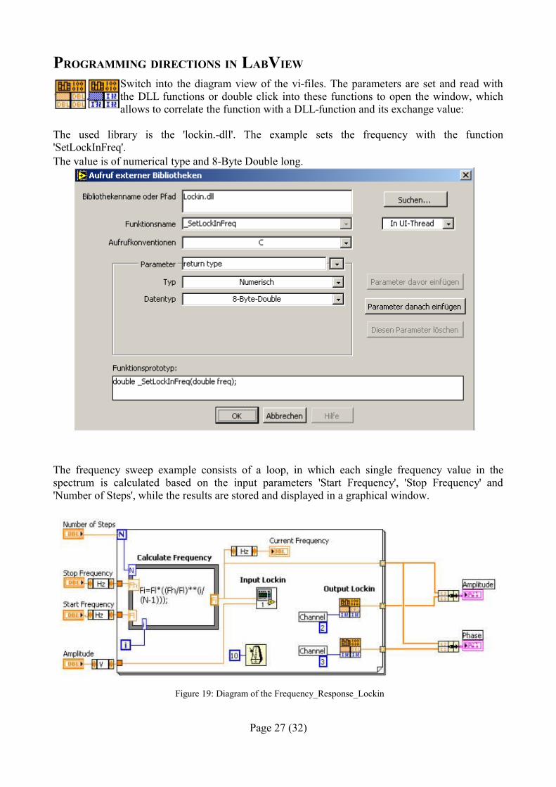
Switch into the diagram view of the vi-files. The parameters are set and read with the DLL functions or double click into these functions to open the window, which allows to correlate the function with a DLL-function and its exchange value:
The used library is the 'lockin.-dll'. The example sets the frequency with the function 'SetLockInFreq'. The value is of numerical type and 8-Byte Double long.
The frequency sweep example consists of a loop, in which each single frequency value in the spectrum is calculated based on the input parameters 'Start Frequency', 'Stop Frequency' and 'Number of Steps', while the results are stored and displayed in a graphical window.
Page 27 (32)
Figure 19: Diagram of the Frequency_Response_Lockin
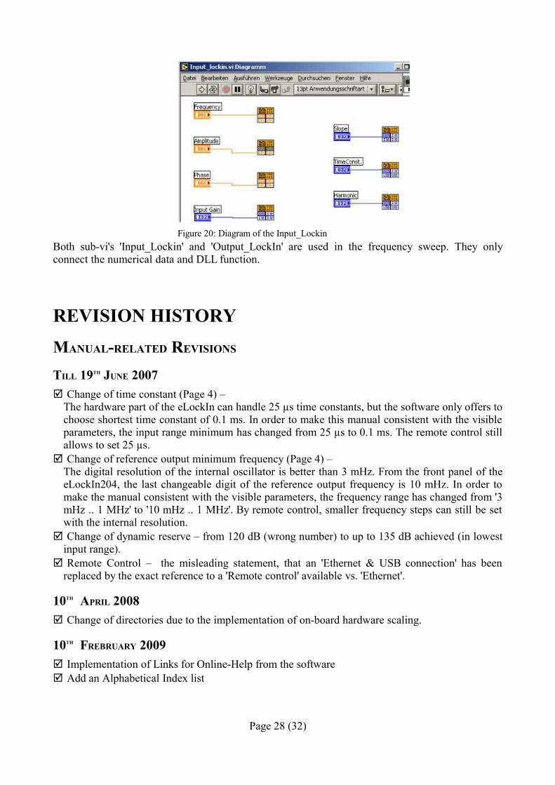
Both sub-vi's 'Input_Lockin' and 'Output_LockIn' are used in the frequency sweep. They only connect the numerical data and DLL function.
REVISION HISTORYMANUAL-RELATED REVISIONS
TILL 19TH JUNE 2007 Change of time constant (Page 4) –
The hardware part of the eLockIn can handle 25 µs time constants, but the software only offers to choose shortest time constant of 0.1 ms. In order to make this manual consistent with the visible parameters, the input range minimum has changed from 25 µs to 0.1 ms. The remote control still allows to set 25 µs.
Change of reference output minimum frequency (Page 4) –The digital resolution of the internal oscillator is better than 3 mHz. From the front panel of the eLockIn204, the last changeable digit of the reference output frequency is 10 mHz. In order to make the manual consistent with the visible parameters, the frequency range has changed from '3 mHz .. 1 MHz' to '10 mHz .. 1 MHz'. By remote control, smaller frequency steps can still be set with the internal resolution.
Change of dynamic reserve – from 120 dB (wrong number) to up to 135 dB achieved (in lowest input range).
Remote Control – the misleading statement, that an 'Ethernet & USB connection' has been replaced by the exact reference to a 'Remote control' available vs. 'Ethernet'.
10TH APRIL 2008 Change of directories due to the implementation of on-board hardware scaling.
10TH FREBRUARY 2009 Implementation of Links for Online-Help from the software Add an Alphabetical Index list
Page 28 (32)
Figure 20: Diagram of the Input_Lockin
HARDWARE REVISIONS
1ST NOVEMBER 2006 – REV 2.2 TO REV 2.3 Change of input noise (Page 4) –
due to an improved board design, the typical noise has reduced to Range Typical noise
10 V < 3 µV1 V < 120 nV0.1 V < 10 nV
For some boards, this noise has been better and specified in the manual separatly. Input resistance from 1 MW to 100 kW Change to input range (stated in the related manual) Change to the input coupling – an 'ac' coupling has been added.
1ST DECEMBER 2006 – REV 2.3 TO REV 2.3A
Dual channel to Quad-Channel (Software change on the internal board, update on older systems only on request – shipment to producer necessary) -- software on request for PCI-board lockins
14TH APRIL 2007 – REV. 2.3A TO REV 2.4 Change of input noise (Page 4) – due to an improved board design, the typical noise has reduced
to:Range Guaranteed noise Typical noise
10 V < 350 nV 280 nV1 V < 80 nV 50 nV0.1 V < 8 nV 5 nV
Change of input range (Page 4) – The visible input ranges (dynamic reserve) in the AMU2.4-software are “high”, “normal” and “low”. Since revision 2.4, the hardware spec meets exactly these values and has changed to ± 5V, ± 500 mV and ± 50 mV, respectively.
Change of input impedance (Page 4) – In order to achieve a better coupling compensation, the input coupling has changed from '100 kOhm' to '100 kOhm || 20 pF'.
10TH APRIL 2008 – REV 2.4 The boards provide an on-board hardware scaling. Therefore, no software file for the scaling is
needed anymore.
SOFTWARE REVISIONS
10TH APRIL 2008 – VERSION 1.02 The whole software package has been reworked concerning the handling of the hardware
scaling. When a program is first called and the PCI-card is capable of on-board hardware scaling, the scaling is read from the EPROM and transferred to the Windows Registry. Multiple cards in
Page 29 (32)
one PC get different entries. When the card does not contain on-board scaling, the 'lockin.ini' is searched and its parameters are transferred to the Registry. Later on, all programs work with the Registry Entries.
Overload function implemented in the DLL.
11TH MAY 2009 – VERSION 1.04 Add the SetLockInParameter call when the Inout Gains are switched, in order to overtake the
phase correction settings for the different gains.
11TH JULY 2009 – VERSION 1.05 Add the function “SetLockInCoupling” in the DLL. Correct the bug “PLL On”: the functions
“SetLockInPhase,”, “SetLockInHarm”, “SetLockInFreq” and “SetLockInAmpl” do not overwrite the PLL setting anymore.
26TH AUGUST 2009 – VERSION 1.06 “SetLockInFreq” reads the external frequency value, when the PLL is ON.
Alphabetical IndexAmplitude...........................................................................................................................................17APIC configuration...........................................................................................................................5, 7bias sweep...........................................................................................................................................21BIAS Sweep........................................................................................................................................21Board..................................................................................................................................................12card.......................................................................................................................................................7Card and Driver installation.................................................................................................................5Card Installation...................................................................................................................................6configuration.....................................................................................................................................5, 7Connections to the card........................................................................................................................7Coupling.............................................................................................................................................16description......................................................................................................................................8, 13directions............................................................................................................................................27DLL in C++ projects...........................................................................................................................23DLL support........................................................................................................................................22DLL-Functions....................................................................................................................................24Driver Installation.................................................................................................................................6Dynamic..............................................................................................................................................16Example programs..............................................................................................................................25Example: Electrical Force Microscope..............................................................................................11File......................................................................................................................................................14Files and Locations.............................................................................................................................25Frequency...........................................................................................................................................17frequency sweep.................................................................................................................................18Frequency Sweep................................................................................................................................17
Page 30 (32)
function line........................................................................................................................................14Functions in the function line.............................................................................................................14Functions in the Menu Line................................................................................................................14General Information.............................................................................................................................4Harmonic............................................................................................................................................17Help....................................................................................................................................................14Input......................................................................................................................................................4installation............................................................................................................................................5Installation............................................................................................................................................6LabView.............................................................................................................................................27LabView Driver and Support..............................................................................................................25Licence for the software.......................................................................................................................5Locations............................................................................................................................................25LockIn...................................................................................................................................................7LockIn Basics.......................................................................................................................................7Mathematical description.....................................................................................................................8Measurements.....................................................................................................................................10Menu Line...........................................................................................................................................14Meters.................................................................................................................................................17Noise Measurements..........................................................................................................................10Option.................................................................................................................................................14Options for the bias sweep.................................................................................................................21Options for the frequency sweep........................................................................................................18Oscilloscope.......................................................................................................................................14Output...................................................................................................................................................4Parameter settings...............................................................................................................................16Phase...................................................................................................................................................17PLL.......................................................................................................................................................4Reference Output..................................................................................................................................4requirements.........................................................................................................................................5Revision History.................................................................................................................................29Revisions..........................................................................................................................................29f.RollOff................................................................................................................................................16settings................................................................................................................................................16Signal Input...........................................................................................................................................4software................................................................................................................................................5Software description...........................................................................................................................13Software installation.............................................................................................................................5Specification of the AMU2.4-LIA........................................................................................................4start.......................................................................................................................................................5Surface and basic description.............................................................................................................25sweep bias...........................................................................................................................................21