44
04/2019 Angle Encoder Modules

04/2019
Angle Encoder Modules
2
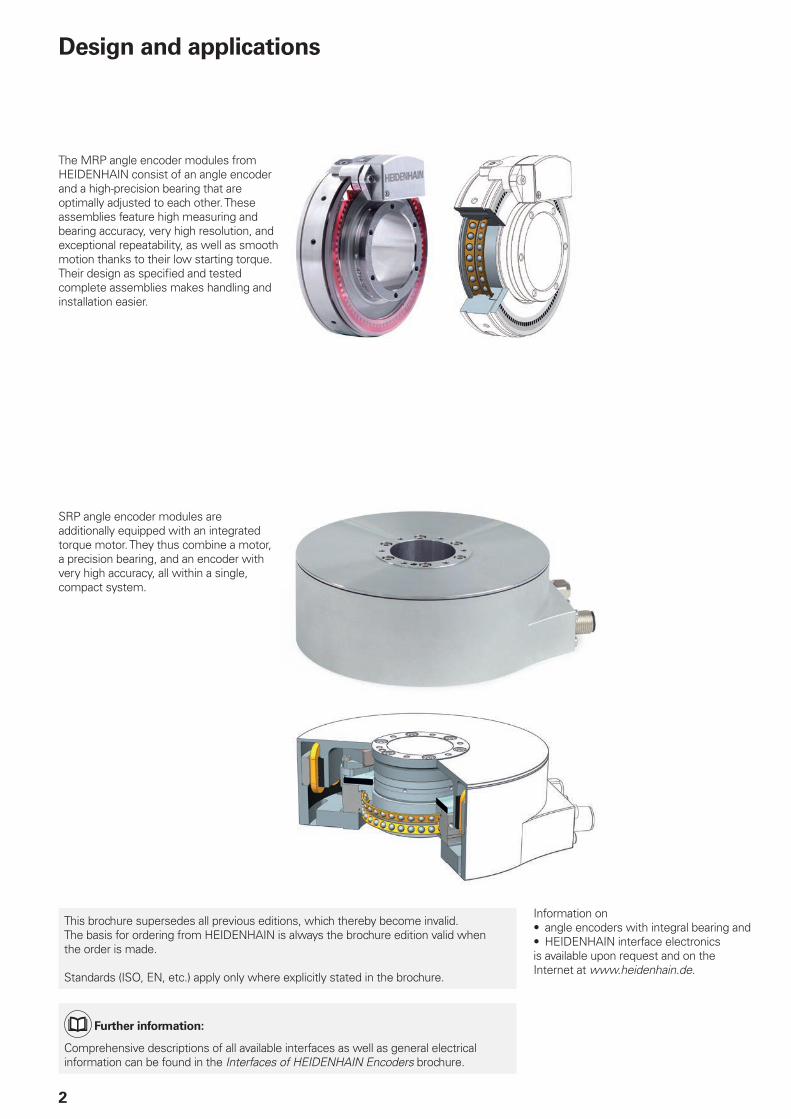
The MRP angle encoder modules from HEIDENHAIN consist of an angle encoder and a high-precision bearing that are optimally adjusted to each other. These assemblies feature high measuring and bearing accuracy, very high resolution, and exceptional repeatability, as well as smooth motion thanks to their low starting torque. Their design as specified and tested complete assemblies makes handling and installation easier.
Information on• angle encoders with integral bearing and• HEIDENHAIN interface electronicsis available upon request and on the Internet at www.heidenhain.de.
Design and applications
SRP angle encoder modules are additionally equipped with an integrated torque motor. They thus combine a motor, a precision bearing, and an encoder with very high accuracy, all within a single, compact system.
This brochure supersedes all previous editions, which thereby become invalid.The basis for ordering from HEIDENHAIN is always the brochure edition valid when the order is made.
Standards (ISO, EN, etc.) apply only where explicitly stated in the brochure.
Further information:
Comprehensive descriptions of all available interfaces as well as general electrical information can be found in the Interfaces of HEIDENHAIN Encoders brochure.
Contents
Technical features and mounting information
Design and applications
2
Measuring and bearing accuracy
6
Information on bearing loads
8
Information on moment of friction and lubrication
9
Information on the motor 10
Mechanical design types and mounting
14
Calibration charts
15
Specifications
Angle encoder modules
With ¬ 10 mm hollow shaft MRP 2000 series
16
With ¬ 35 mm hollow shaft MRP 5000 series
20
With ¬ 100 mm hollow shaft MRP 8000 series 26
Angle encoder modules with integrated torque motor
With ¬ 32 mm hollow shaft SRP 5000 series 32
Position controllers AccurET 38
Electrical connection
Interfaces » 1 VPP incremental signals
39
EnDat position values
40
Motor 41
Cables 42

4
SetupSince HEIDENHAIN manufactures the bearings as well as the encoders, these two functional assemblies are highly integrated. Fewer components are necessary than in conventional solutions, thereby resulting in fewer joints. This permits a very compact and rigid design with particularly low profiles. Currently, angle encoder modules are available with 10 mm, 35 mm and 100 mm hollow shafts. Angle encoder modules with an integrated motor are currently available with a 32 mm hollow shaft.
Design and applications
AdvantagesAngle encoder modules are the combination of a bearing and an encoder. HEIDENHAIN has already completed the necessary assembly and adjustment work. As a result, the characteristics of the angle encoder modules have already been defined and tested in accordance with the customer’s desired specifications. Thanks to the simple mechanical interfaces, all critical mounting processes are eliminated. Not only does this greatly simplify the installation process, but it also ensures that the specified accuracy is attained in the application. The effort-intensive matching of all of the individual components to each other and to the machine environment is not necessary, nor is time-consuming testing.
PropertiesThe rolling bearings used are specifically adapted to the requirements of high-precision rotary axes. Their essential characteristics are very high guideway accuracies, high rigidities, low starting torques, and steady continuous torques. At the same time, value was placed on attaining the most compact dimensions possible and on keeping the mass low. High speeds and high load ratings are not of primary importance.
These encoders comply with the high requirements of metrology applications and with those of the electronics industry. Key features include their very high resolution, excellent signal quality, and exceptional repeatability—even under varying operating temperatures. The assemblies are available with either incremental or absolute encoders.
The SRP angle encoder module, which is additionally equipped with an integrated torque motor enables smooth motion control. Due to the motor’s virtual lack of cogging torque and radial force, the high guideway accuracy of the bearing is not negatively influenced.
Comparison of a “conventional” precision axis setup and a solution with an angle encoder module from HEIDENHAIN

5
Reproducible guideway accuracy: a decisive characteristic of the bearingThe absolute guideway accuracy of an unloaded air bearing is often superior to that of a rolling bearing. However, in many applications, having the highest possible reproducible guideway accuracy of the bearing is what matters. In this regard, angle encoder modules from HEIDENHAIN can represent an excellent alternative to air-bearing axes. This is because the rolling bearings from HEIDENHAIN exhibit exceptional repeatability, and because the rigidity of the HEIDENHAIN rolling bearings is higher than comparable values for air bearings by at least a factor of 10. Thus, for axes that are subjected to loads, HEIDENHAIN rolling bearings are the more accurate solution. In addition, rolling bearings are generally less sensitive to shock loads and do not require a regulated air supply—so they are more robust and easier to use.
Areas of applicationThe angle encoder modules are designed for low to medium speeds and medium-sized loads at high to very high bearing accuracy and extremely high repeatability. They are well suited to the special requirements of metrology applications. Typical applications thus include laser trackers in the metrology industry, high-precision rotary tables on measuring machines, and wafer-handling machines in the electronics industry. Angle encoder modules can also be used on machine tools that handle small loads, such as electrical discharge machines or in laser beam machining.
Wafer handling
Compact tilting units
High-precision rotary tables
Laser trackers
Practical solutionsWith the angle encoder modules from HEIDENHAIN, the bearing can be adapted to specific customer needs. The preloading, lubrication, contact angle, and materials can be adapted individually to the respective requirements as needed. For more information, please get in touch with your contact person at HEIDENHAIN.

Y
X
Z
Y
X
Z
Dpw
h
6
Wobble of the axis
Measuring and bearing accuracy
The accuracy of completely assembled angle encoder modules from HEIDENHAIN depends on the measuring accuracy of their integrated angle encoders and the bearing accuracy of their rolling bearings.
When evaluating the quality of an angle encoder module, HEIDENHAIN takes the following measuring and bearing accuracies into account:
Measuring accuraciesFor the measuring accuracies of the integrated angle encoder, the system accuracy and repeatability are of decisive importance for the specification of the angle encoder module.
The system accuracy of the angle encoder represents the position error within a single revolution and applies to the entire range of the specified centered load.
Guideway error in measuring plane 2
Ideal axis of rotation
Guideway error in measuring plane 1
Position of the axis of rotation at the rotation angle ϕ
Measurement of axial runout
Measurement of radial runout
Precision sphere for measurement
Measurement of the axial and radial guideway accuracy with five length gauges
Measured values and measuring locations on the rolling bearing (schematic representation)
Dpw = Pitch diameter of rolling bearing
A distinction is made between single-sided and double-sided repeatability. Single-sided repeatability applies to any number of revolutions as long as the direction of rotation does not change during the measurement. Individual points are approached multiple times, and the maximum deviation among the measured points is determined. This evaluation is performed by means of a comparison with a reference encoder.
For determining the double-sided repeatability, the direction of rotation is switched during the measurement. Each point is then approached alternatingly from one side and then from the other. The maximum deviation of the measured points among each other is thereby determined. A reference encoder is used for positioning.
For both values, the absolute deviation compared with the reference is inconse-quential and is not the goal of the measure-ment.
Bearing accuraciesFor the evaluation of the bearing accuracy, the oft-cited radial runout accuracy is not as important as the guideway accuracy of the bearing. The guideway accuracy is the deviation of the actual axis of rotation from the ideal nominal axis of rotation of the bearing. The radial and axial guideway accuracy of the bearing, as well as the wobble, are determined for the evaluation.
The guideway accuracy is measured with the aid of a calibration standard, such as a ceramic sphere with a known roundness. The center point of the sphere is positioned at a defined distance vertically above the center of the bearing raceway. For the sake of a standardized measurement, this distance is usually the pitch diameter Dpw of the bearing.
Two length gauges are used for measuring the radial guideway accuracy. They are positioned at a 90° angle to each other at the height of the sphere center. When the bearing is rotated, they measure each radial deviation of the sphere in the X and Y directions.
t
t
r
7
Measurement of axial runout
Measurement of radial runout
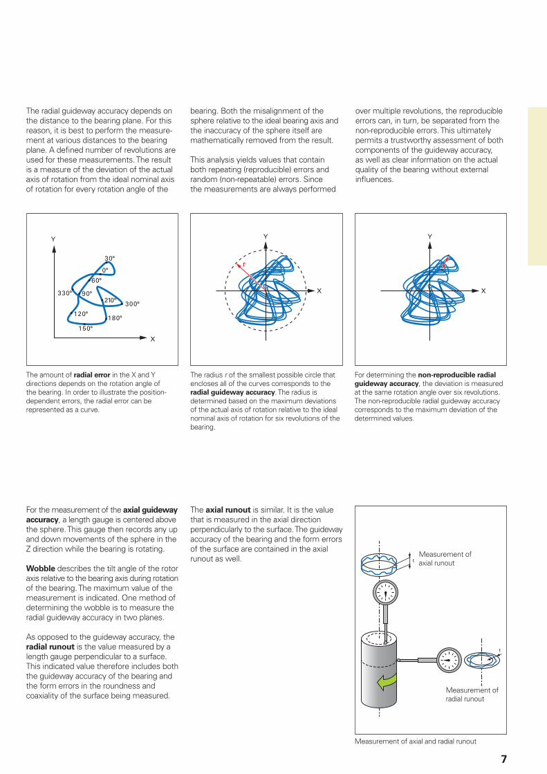
The radial guideway accuracy depends on the distance to the bearing plane. For this reason, it is best to perform the measure-ment at various distances to the bearing plane. A defined number of revolutions are used for these measurements. The result is a measure of the deviation of the actual axis of rotation from the ideal nominal axis of rotation for every rotation angle of the
bearing. Both the misalignment of the sphere relative to the ideal bearing axis and the inaccuracy of the sphere itself are mathematically removed from the result.
This analysis yields values that contain both repeating (reproducible) errors and random (non-repeatable) errors. Since the measurements are always performed
over multiple revolutions, the reproducible errors can, in turn, be separated from the non-reproducible errors. This ultimately permits a trustworthy assessment of both components of the guideway accuracy, as well as clear information on the actual quality of the bearing without external influences.
For the measurement of the axial guideway accuracy, a length gauge is centered above the sphere. This gauge then records any up and down movements of the sphere in the Z direction while the bearing is rotating.
Wobble describes the tilt angle of the rotor axis relative to the bearing axis during rotation of the bearing. The maximum value of the measurement is indicated. One method of determining the wobble is to measure the radial guideway accuracy in two planes.
As opposed to the guideway accuracy, the radial runout is the value measured by a length gauge perpendicular to a surface. This indicated value therefore includes both the guideway accuracy of the bearing and the form errors in the roundness and coaxiality of the surface being measured.
The axial runout is similar. It is the value that is measured in the axial direction perpendicularly to the surface. The guideway accuracy of the bearing and the form errors of the surface are contained in the axial runout as well.
The amount of radial error in the X and Y directions depends on the rotation angle of the bearing. In order to illustrate the position-dependent errors, the radial error can be represented as a curve.
The radius r of the smallest possible circle that encloses all of the curves corresponds to the radial guideway accuracy. The radius is determined based on the maximum deviations of the actual axis of rotation relative to the ideal nominal axis of rotation for six revolutions of the bearing.
For determining the non-reproducible radial guideway accuracy, the deviation is measured at the same rotation angle over six revolutions. The non-reproducible radial guideway accuracy corresponds to the maximum deviation of the determined values.
Measurement of axial and radial runout
0
0 90 180 270 360
2.5
-2.5
-5
5
0
0 90 180 270 360
2.5
-2.5
-5
5
8
Information on bearing loads
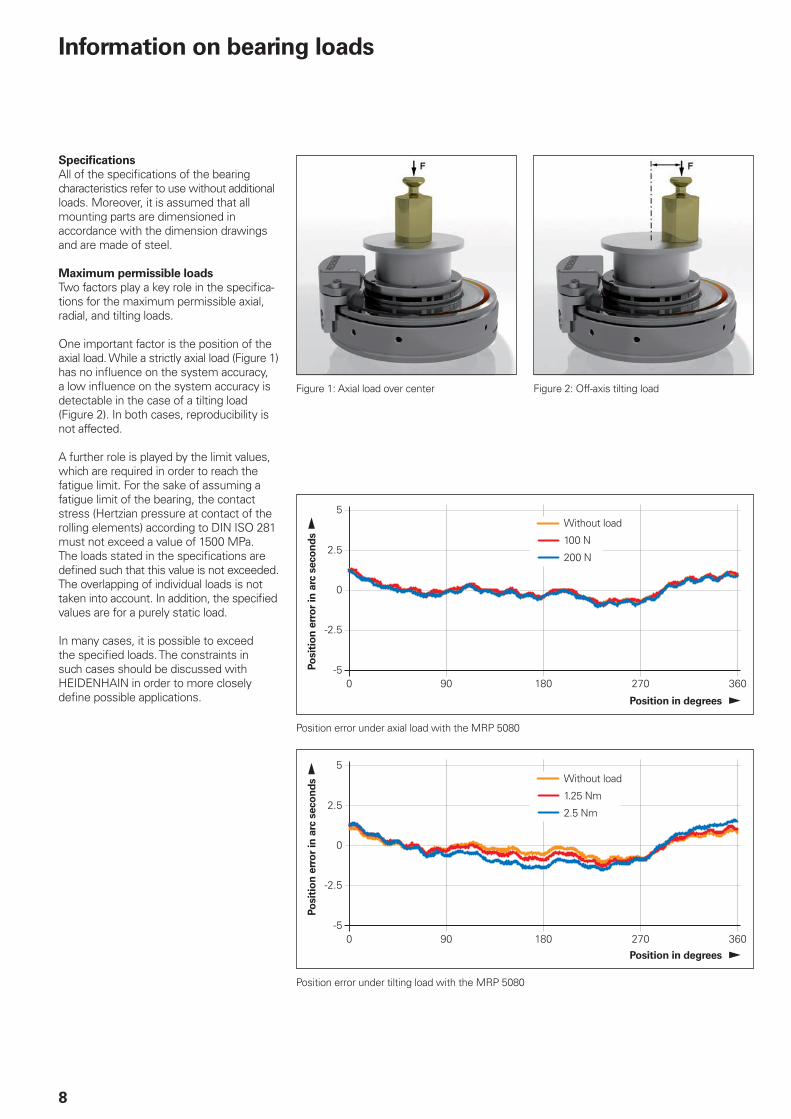
SpecificationsAll of the specifications of the bearing characteristics refer to use without additional loads. Moreover, it is assumed that all mounting parts are dimensioned in accordance with the dimension drawings and are made of steel.
Maximum permissible loadsTwo factors play a key role in the specifica-tions for the maximum permissible axial, radial, and tilting loads.
One important factor is the position of the axial load. While a strictly axial load (Figure 1) has no influence on the system accuracy, a low influence on the system accuracy is detectable in the case of a tilting load (Figure 2). In both cases, reproducibility is not affected.
A further role is played by the limit values, which are required in order to reach the fatigue limit. For the sake of assuming a fatigue limit of the bearing, the contact stress (Hertzian pressure at contact of the rolling elements) according to DIN ISO 281 must not exceed a value of 1500 MPa. The loads stated in the specifications are defined such that this value is not exceeded. The overlapping of individual loads is not taken into account. In addition, the specified values are for a purely static load.
In many cases, it is possible to exceed the specified loads. The constraints in such cases should be discussed with HEIDENHAIN in order to more closely define possible applications.
Figure 1: Axial load over center Figure 2: Off-axis tilting load
Position in degrees
Posi
tio
n e
rro
r in
arc
sec
on
ds
Without load
100 N
200 N
Position in degrees
Posi
tio
n e
rro
r in
arc
sec
on
ds Without load
1.25 Nm
2.5 Nm
Position error under axial load with the MRP 5080
Position error under tilting load with the MRP 5080
0 1002
4
68
10
12
14
1618
20 30 40 50
9
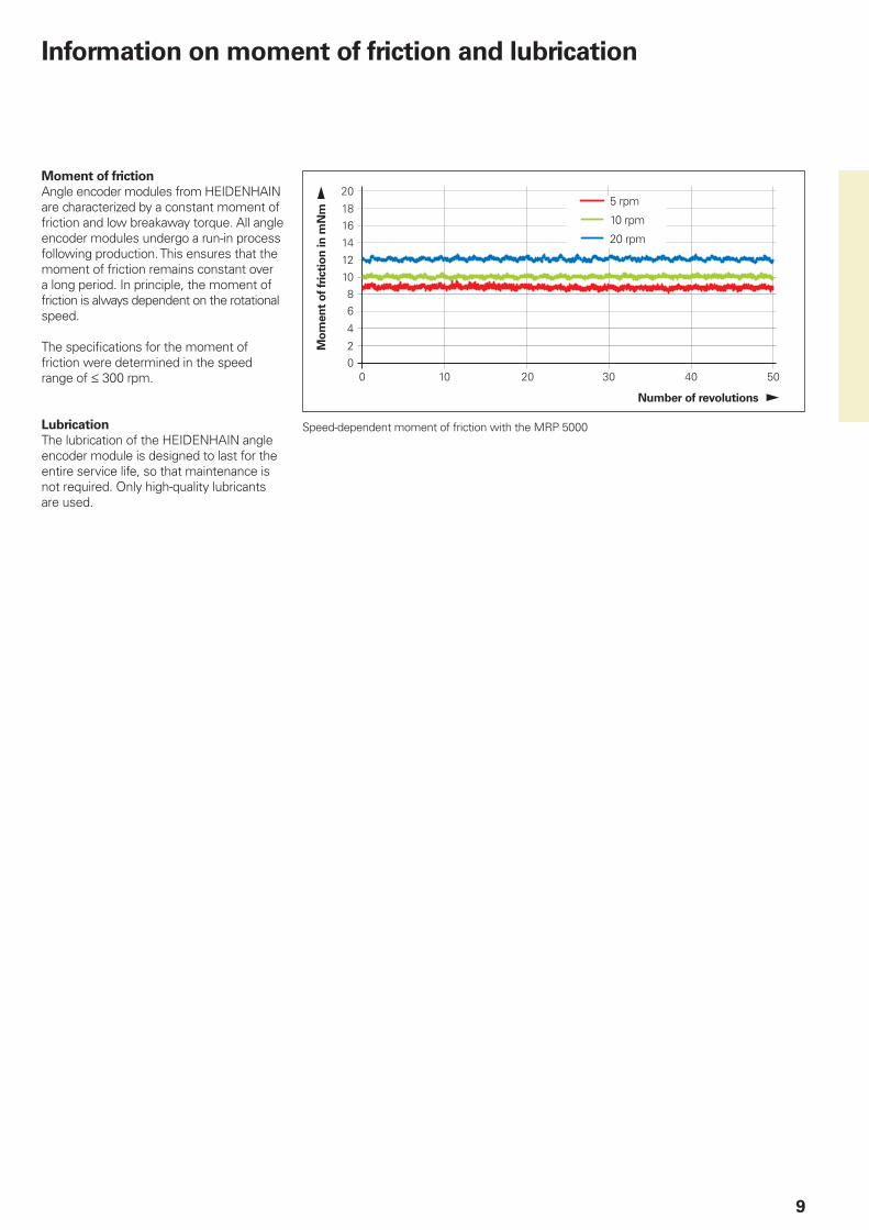
Moment of frictionAngle encoder modules from HEIDENHAIN are characterized by a constant moment of friction and low breakaway torque. All angle encoder modules undergo a run-in process following production. This ensures that the moment of friction remains constant over a long period. In principle, the moment of friction is always dependent on the rotational speed.
The specifications for the moment of friction were determined in the speed range of 300 rpm.
LubricationThe lubrication of the HEIDENHAIN angle encoder module is designed to last for the entire service life, so that maintenance is not required. Only high-quality lubricants are used.
Number of revolutions
Mo
men
t o
f fri
ctio
n in
mN
m 5 rpm
10 rpm
20 rpm
Speed-dependent moment of friction with the MRP 5000
Information on moment of friction and lubrication

10
Information on the motor
Slotless torque motorThe motor, which was specially developed for the SRP angle encoder module, meets even the highest requirements placed on high-precision rotary axes.
The motor is cogging-free and produces no disturbing influences on the high-accuracy bearing. This allows for exceptionally uniform motion control and positioning accuracy.
The drive uses a slotless, iron-core torque motor. This motor therefore combines two normally contradictory characteristics—high torque density and low cogging torque. This type of motor omits the slots that are found in conventional designs, with self-retaining coils used instead.
Thanks to the motor’s special design and the particularly symmetrical arrangement of all of its components, the rotor is always exposed to a constant magnetic field throughout its entire rotation.
An iron return ring enables a comparatively large amount of torque. All of this results in the following benefits:• Extremely low cogging torque• No interfering radial forces• Medium-sized torques• High dynamics in controlled operation• Low thermal power loss• Compact dimensions
Protection from thermal overloadingThe SRP 5000 series devices can be operated under the following conditions. The ambient and mounting conditions must be complied with in accordance with the data provided in the data sheet.
Motor in operation (shaft speed ≠ 0):• At continuous current (Ic): for a very long
(unlimited) amount of time• At maximum current (Ip): for up to 1 s.
The maximum current (Ip) must not be exceeded
• With currents between continuous current (Ic) and maximum current (Ip) that flow for longer than 1 s, protection against thermal overloading must be implemented via an I2t monitor in the controller electronics
Motor at standstill (shaft speed = 0):• At stall current (Is): for a very long
(unlimited) amount of time• At continuous current (Ic): for up to
3 minutes.
Slotless iron-core permanent-magnet-excited AC synchronous motor
Self-retaining coils
Iron return ring
Rotor with magnets
For protection against thermal overloading, suitable measures are required in the controller electronics (e.g., an I2t monitor). Direct monitoring of the temperature by means of temperature sensors in the motor windings is not possible.
If the instantaneous current value exceeds the I2t RMS current limit, then an integrator circuit is activated. If the integrator circuit reaches the I2t time limit, then the controller must stop the current supply to the motor.
I2t RMS current limit = Is motor at standstill (speed = 0)
= Ic motor in operation (speed ≠ 0)
I2t time limit = (Ip2 – Ic
2) · t
-5
-4
-3
-2
-1
0
1
2
3
4
5
0 0,1 0,2 0,3 0,4 0,5 0,6 0,7 0,8 0,9 1
0 90 180 270 360
1
0.8
0.6
0.4
0.2
00 500
1.0004
1.0003
1.0002
1.0001
1.0000
0.9999
0.9998
1000 1500 2000 2500
1000500 1500
11
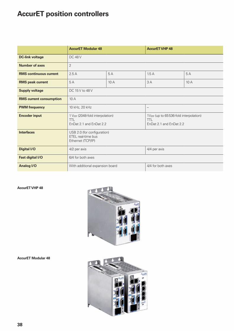
Operation with AccurET position controllersThe AccurET position controllers are the perfect complement to the SRP angle encoder modules. With them, top performance can be attained in terms of dynamics and position stability.
The compact AccurET position controllers accommodate a broad range of voltages and currents. This greatly simplifies the integration of different servo motors into a single machine.
Multiple position controllers connected to the same DC bus voltage can be supplied by a single power supply. Each controller can drive two axes.
Since the position controllers do not require a mounting rack, the amount of space required depends only on the number of axes to be controlled. The simplified power and communication cabling, as well as the modular cooling unit, facilitates the installation and maintenance of the machine.
With the recommended AccurET controllers from ETEL, the characteristics for protection against thermal overloading are already integrated.
AccurET Modular 48: The AccurET Modular 48 controller is available in two versions. One version permits the installation of an optional card, such as the UltimET motion controller or the I/O card.
AccurET VHP 48:Controller with a high-speed encoder input and special supply module for applications with very high synchronization and position accuracy demands.
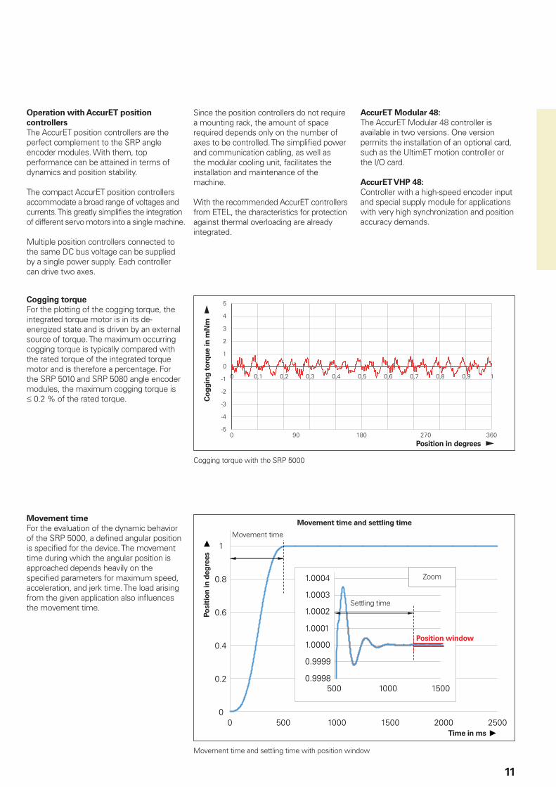
Cogging torqueFor the plotting of the cogging torque, the integrated torque motor is in its de-energized state and is driven by an external source of torque. The maximum occurring cogging torque is typically compared with the rated torque of the integrated torque motor and is therefore a percentage. For the SRP 5010 and SRP 5080 angle encoder modules, the maximum cogging torque is 0.2 % of the rated torque.
Position in degrees
Co
gg
ing
to
rqu
e in
mN
m
Cogging torque with the SRP 5000
Movement timeFor the evaluation of the dynamic behavior of the SRP 5000, a defined angular position is specified for the device. The movement time during which the angular position is approached depends heavily on the specified parameters for maximum speed, acceleration, and jerk time. The load arising from the given application also influences the movement time.
Movement time and settling time with position window
Movement time and settling time
Movement time
Zoom
Posi
tio
n in
deg
rees
Time in ms
Position window
Settling time
12
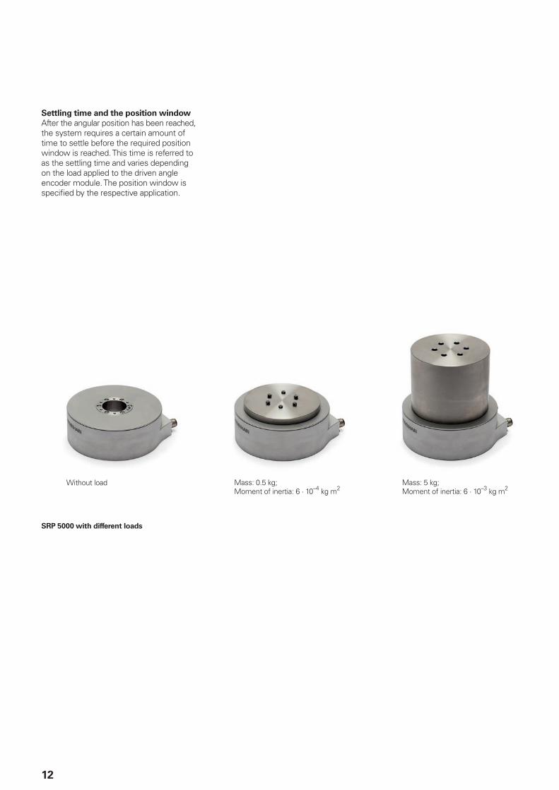
Settling time and the position windowAfter the angular position has been reached, the system requires a certain amount of time to settle before the required position window is reached. This time is referred to as the settling time and varies depending on the load applied to the driven angle encoder module. The position window is specified by the respective application.
SRP 5000 with different loads
Without load Mass: 0.5 kg; Moment of inertia: 6 · 10–4 kg m2
Mass: 5 kg; Moment of inertia: 6 · 10–3 kg m2
0.01
0
0.1
0.2
0.3
0.4
0.5
0.1 1 10 100
0
0.1
0.2
0.3
0.4
0.5
0.01 0.1 1 10 100
13
Mov
emen
t tim
e an
d se
ttlin
g tim
e in
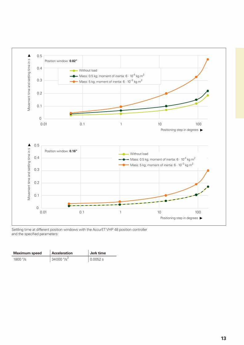
s Position window: 0.02”
Without load
Mass: 0.5 kg; moment of inertia: 6 · 10-4 kg m2
Mass: 5 kg; moment of inertia: 6 · 10–3 kg m2
Positioning step in degrees
Mov
emen
t tim
e an
d se
ttlin
g tim
e in
s Position window: 0.16”Without load
Mass: 0.5 kg; moment of inertia: 6 · 10-4 kg m2
Mass: 5 kg; moment of inertia: 6 · 10–3 kg m2
Positioning step in degrees
Settling time at different position windows with the AccurET VHP 48 position controller and the specified parameters:
Maximum speed Acceleration Jerk time
1800 °/s 34 000 °/s2 0.0052 s

14
Mechanical design types and mounting
Electromagnetic compatibilityFor devices with an IP00 rating, the customer must provide a suitable protective cap and shield connection.
Protection against environmental factorsSuitable measures must be employed in order to protect the devices from environmental factors. The information in the Specifications must be complied with.
Mounting options of the MRP 5010 devices
Connect the shield to the crimp sleeve.Provide strain relief for the cable!
Mounting option 1
Mounting option 2
1 = Required direction for axial forces on the rotor2 = Rotor3 = Stator
The angle encoder module consists of an already preloaded bearing unit with a mounted angle encoder.
Proper mounting is critical for ensuring good guideway accuracy for the bearing. During mounting, please observe the following: • The flatness of the mounting parts • Compliance with the specified screw
torque values • The screw tightening sequence• The specified load direction• The transferable torque of the respective
joints
A precise alignment of the angle encoder module is not required, because the angle encoder module and bearing are already ideally aligned to each other. Centering collars on the mounting parts, however, can facilitate mounting.
Angle encoder modules must not be combined or stressed with a second fixed bearing. If another support bearing is required, then it must be designed as a floating bearing.
Materials for mountingThe mounting parts must be made of steel. The material must exhibit a coefficient of thermal expansion of a = (10 to 16) x 10–6K–1. Additionally, the material must meet the following specifications:• Re 235 N/mm2
• Rm 400 N/mm2
15
Calibration charts
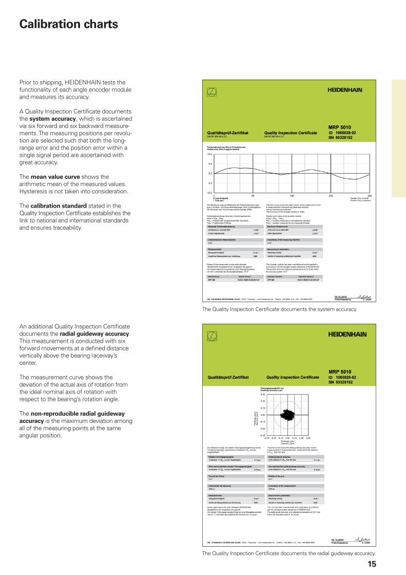
Prior to shipping, HEIDENHAIN tests the functionality of each angle encoder module and measures its accuracy.
A Quality Inspection Certificate documents the system accuracy, which is ascertained via six forward and six backward measure-ments. The measuring positions per revolu-tion are selected such that both the long-range error and the position error within a single signal period are ascertained with great accuracy.
The mean value curve shows the arithmetic mean of the measured values. Hysteresis is not taken into consideration.
The calibration standard stated in the Quality Inspection Certificate establishes the link to national and international standards and ensures traceability.
The Quality Inspection Certificate documents the system accuracy.
The Quality Inspection Certificate documents the radial guideway accuracy.
An additional Quality Inspection Certificate documents the radial guideway accuracy. This measurement is conducted with six forward movements at a defined distance vertically above the bearing raceway’s center.
The measurement curve shows the deviation of the actual axis of rotation from the ideal nominal axis of rotation with respect to the bearing’s rotation angle.
The non-reproducible radial guideway accuracy is the maximum deviation among all of the measuring points at the same angular position.

MRP 2010 MRP 2080
16
MRP 2000 seriesAngle encoder modules with integrated encoder and bearing• Particularly compact dimensions• High measuring and bearing accuracy• Hollow shaft ¬ 10 mm
Encoder characteristics IncrementalMRP 2080
AbsoluteMRP 2010
Measuring standard DIADUR circular scale
Signal periods 2048
System accuracy* ±7”
Position error per signal period ±1.5”
Repeatability From both directions: 3”
RMS position noise Typically 0.07” Typically 0.01”
Interface » 1 VPP EnDat 2.2
Ordering designation – EnDat22
Position values per revolution – 25 bits
Clock frequencyCalculation time tcal
– 16 MHz 7 µs
Reference marks 1 –
Cutoff frequency –3 dB 210 kHz –
Electrical connection 14-pin header; adapter cable with quick connector as accessory
12-pin
Cable length 30 m (with HEIDENHAIN cable)
Supply voltage DC 5 V ±0.25 V DC 3.6 V to 14 V
Power consumption (max.) 5.25 V: 700 mW 3.6 V: 0.6 W 14 V: 0.7 W
Current consumption (typical) Without load: IP = 60 mA; max. 120 mA With load: max. 130 mA
5 V: 85 mA (without load)
* Please select when ordering

17
Bearing properties IncrementalMRP 2080
AbsoluteMRP 2010
Shaft Hollow through shaft D = 10 mm
Max. permissible axial load3) 50 N (centered load)
Max. permissible radial load3) 45 N
Max. permissible tilting torque3) 0.8 Nm
Contact stiffness Axial: 54 N/µmRadial: 153 N/µm(calculated values)
Resistance to tilt 2.16 Nm/mrad (calculated value)
Mechanically perm. speed 2000 rpm
Moment of friction 0.020 Nm
Starting torque 0.010 Nm
Max. transferable shaft torque3) 0.3 Nm
Moment of inertia of rotor 3.5 · 10–6 kgm2
Radial guideway accuracy Measured at distance h = 52 mm from the ball race: 0.60 µm
Non-reproducible radial guideway accuracy
Measured at distance h = 52 mm from the ball race: 0.70 µm
Axial guideway accuracy ±0.3 µm
Axial runout of the surface 8 µm
Wobble of the axis 2.5”
Vibration 55 Hz to 2000 HzShock 6 ms
200 m/s2 (EN 60068-2-6) 100 m/s2 (EN 60068-2-27)(without load)
Protection EN 605292) IP001)
Operating temperatureStorage temperature
0 °C to 50 °C0 °C to 50 °C
Relative air humidity 75 % without condensation
Mass 0.12 kg (without cable or connector)
1) Electromagnetic compatibility must be ensured in the complete system through appropriate installation measures2) When mounted3) Purely static load, without additional vibrations or shock load

18
MRP 2000 seriesMRP 2010, MRP 2080
1 = Tightening torque of the M2.5 – 8.8 cylinder head screws: 0.6 Nm ±0.03 Nm2 = Tightening torque of the M4 – 8.8 cylinder head screws: 2.5 Nm ±0.13 Nm3 = Marking of the 0° position ±5°4 = Direction of rotation for ascending position values5 = Required direction for axial forces
19
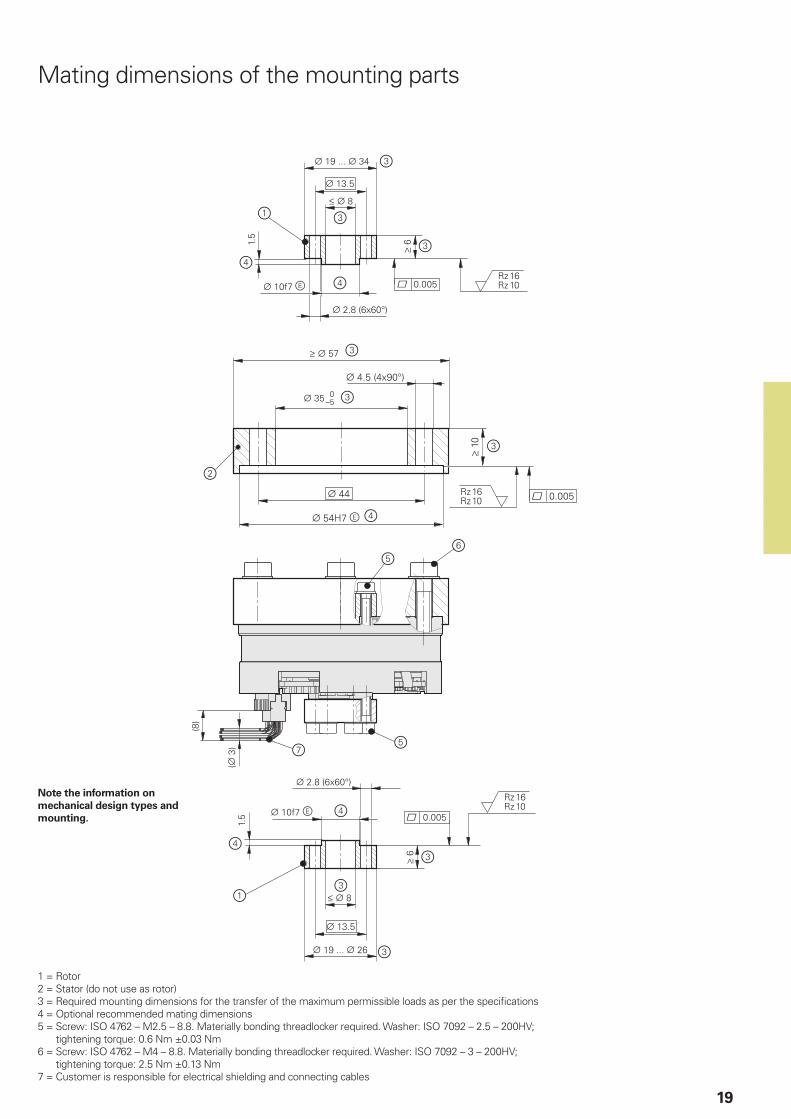
Mating dimensions of the mounting parts
1 = Rotor2 = Stator (do not use as rotor)3 = Required mounting dimensions for the transfer of the maximum permissible loads as per the specifications4 = Optional recommended mating dimensions5 = Screw: ISO 4762 – M2.5 – 8.8. Materially bonding threadlocker required. Washer: ISO 7092 – 2.5 – 200HV;
tightening torque: 0.6 Nm ±0.03 Nm6 = Screw: ISO 4762 – M4 – 8.8. Materially bonding threadlocker required. Washer: ISO 7092 – 3 – 200HV;
tightening torque: 2.5 Nm ±0.13 Nm7 = Customer is responsible for electrical shielding and connecting cables
Note the information on mechanical design types and mounting.
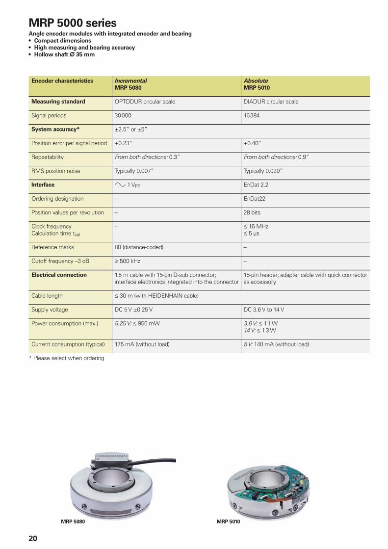
MRP 5010MRP 5080
20
MRP 5000 seriesAngle encoder modules with integrated encoder and bearing• Compact dimensions• High measuring and bearing accuracy• Hollow shaft ¬ 35 mm
Encoder characteristics IncrementalMRP 5080
AbsoluteMRP 5010
Measuring standard OPTODUR circular scale DIADUR circular scale
Signal periods 30 000 16 384
System accuracy* ±2.5” or ±5”
Position error per signal period ±0.23” ±0.40”
Repeatability From both directions: 0.3” From both directions: 0.9”
RMS position noise Typically 0.007” Typically 0.020”
Interface » 1 VPP EnDat 2.2
Ordering designation – EnDat22
Position values per revolution – 28 bits
Clock frequencyCalculation time tcal
– 16 MHz 5 µs
Reference marks 80 (distance-coded) –
Cutoff frequency –3 dB 500 kHz –
Electrical connection 1.5 m cable with 15-pin D-sub connector; interface electronics integrated into the connector
15-pin header; adapter cable with quick connector as accessory
Cable length 30 m (with HEIDENHAIN cable)
Supply voltage DC 5 V ±0.25 V DC 3.6 V to 14 V
Power consumption (max.) 5.25 V: 950 mW 3.6 V: 1.1 W14 V: 1.3 W
Current consumption (typical) 175 mA (without load) 5 V: 140 mA (without load)
* Please select when ordering
21
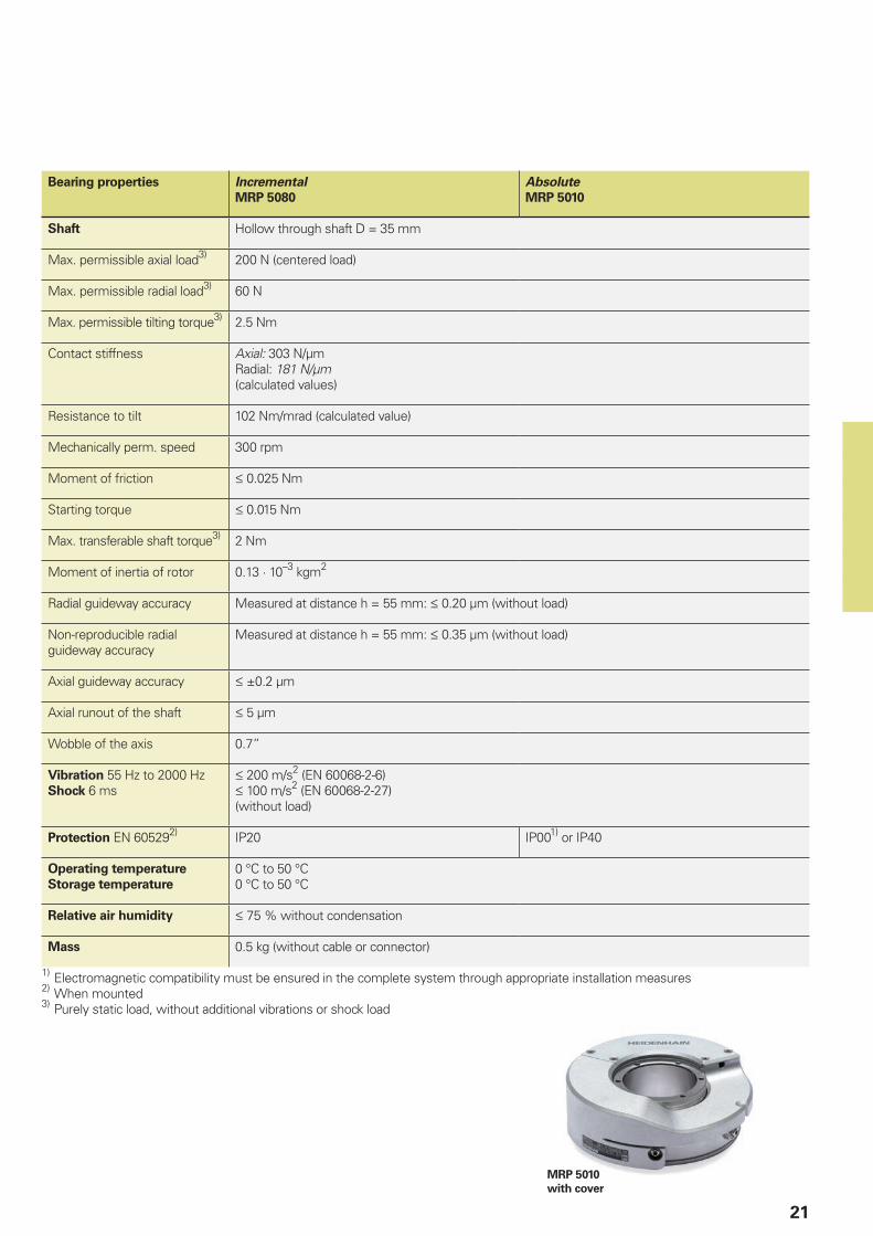
MRP 5010 with cover
Bearing properties IncrementalMRP 5080
AbsoluteMRP 5010
Shaft Hollow through shaft D = 35 mm
Max. permissible axial load3) 200 N (centered load)
Max. permissible radial load3) 60 N
Max. permissible tilting torque3) 2.5 Nm
Contact stiffness Axial: 303 N/µmRadial: 181 N/µm(calculated values)
Resistance to tilt 102 Nm/mrad (calculated value)
Mechanically perm. speed 300 rpm
Moment of friction 0.025 Nm
Starting torque 0.015 Nm
Max. transferable shaft torque3) 2 Nm
Moment of inertia of rotor 0.13 · 10–3 kgm2
Radial guideway accuracy Measured at distance h = 55 mm: 0.20 µm (without load)
Non-reproducible radial guideway accuracy
Measured at distance h = 55 mm: 0.35 µm (without load)
Axial guideway accuracy ±0.2 µm
Axial runout of the shaft 5 µm
Wobble of the axis 0.7”
Vibration 55 Hz to 2000 HzShock 6 ms
200 m/s2 (EN 60068-2-6) 100 m/s2 (EN 60068-2-27)(without load)
Protection EN 605292) IP20 IP001) or IP40
Operating temperatureStorage temperature
0 °C to 50 °C0 °C to 50 °C
Relative air humidity 75 % without condensation
Mass 0.5 kg (without cable or connector)
1) Electromagnetic compatibility must be ensured in the complete system through appropriate installation measures2) When mounted3) Purely static load, without additional vibrations or shock load
22
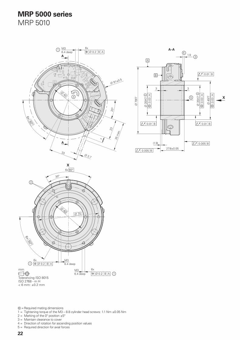
MRP 5000 seriesMRP 5010
Ⓚ = Required mating dimensions1 = Tightening torque of the M3 – 8.8 cylinder head screws: 1.1 Nm ±0.05 Nm2 = Marking of the 0° position ±5°3 = Maintain clearance to cover4 = Direction of rotation for ascending position values5 = Required direction for axial forces

23
1 = Tightening torque of the M3 – 8.8 cylinder head screws: 1.1 Nm ±0.05 Nm2 = Marking of the 0° position ±5°3 = Direction of rotation for ascending position values4 = Required direction for axial forces
MRP 5010 with cover
24
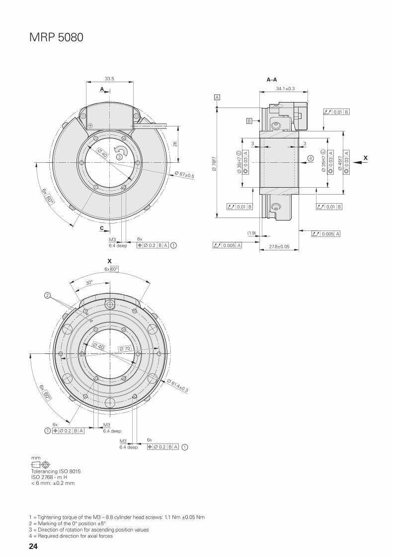
MRP 5080
1 = Tightening torque of the M3 – 8.8 cylinder head screws: 1.1 Nm ±0.05 Nm2 = Marking of the 0° position ±5°3 = Direction of rotation for ascending position values4 = Required direction for axial forces
2.1
MRP 5010/MRP 5080
MRP 5010
MRP 5010/MRP 5080
25
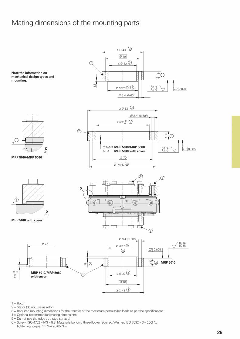
Mating dimensions of the mounting parts
1 = Rotor2 = Stator (do not use as rotor)3 = Required mounting dimensions for the transfer of the maximum permissible loads as per the specifications4 = Optional recommended mating dimensions5 = Do not use the edge as a stop surface!6 = Screw: ISO 4762 – M3 – 8.8. Materially bonding threadlocker required. Washer: ISO 7092 – 3 – 200HV;
tightening torque: 1.1 Nm ±0.05 Nm
MRP 5010 with cover
MRP 5010/MRP 5080 with cover
Note the information on mechanical design types and mounting.
MRP 5010 with cover

MRP 8010MRP 8080
26
MRP 8000 seriesAngle encoder modules with integrated encoder and bearing• Compact dimensions• High measuring and bearing accuracy• Hollow shaft ¬ 100 mm
Encoder characteristics IncrementalMRP 8080
AbsoluteMRP 8010
Measuring standard OPTODUR circular scale DIADUR circular scale
Signal periods 63 000 32 768
System accuracy* ±1” or ±2”
Position error per signal period ±0.10” ±0.20”
Repeatability From both directions: 0.2” From both directions: 0.5”
RMS position noise Typically 0.003” Typically 0.010”
Interface » 1 VPP EnDat 2.2
Ordering designation – EnDat22
Position values per revolution – 29 bits
Clock frequencyCalculation time tcal
– 16 MHz 5 µs
Reference marks 150 (distance-coded) –
Cutoff frequency –3 dB 500 kHz –
Electrical connection 1.5 m cable with 15-pin D-sub connector; interface electronics integrated into the connector
15-pin header; adapter cable with quick connector as accessory
Cable length 30 m (with HEIDENHAIN cable)
Supply voltage DC 5 V ±0.25 V DC 3.6 V to 14 V
Power consumption (max.) 5.25 V: 950 mW 3.6 V: 1.1 W 14 V: 1.3 W
Current consumption (typical) 175 mA (without load) 5 V: 140 mA (without load)
* Please select when ordering
27
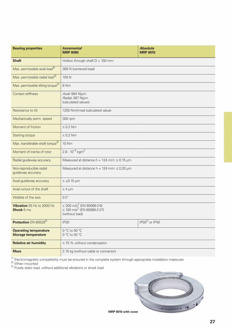
MRP 8010 with cover
Bearing properties IncrementalMRP 8080
AbsoluteMRP 8010
Shaft Hollow through shaft D = 100 mm
Max. permissible axial load3) 300 N (centered load)
Max. permissible radial load3) 100 N
Max. permissible tilting torque3) 6 Nm
Contact stiffness Axial: 684 N/µmRadial: 367 N/µm(calculated values)
Resistance to tilt 1250 Nm/mrad (calculated value)
Mechanically perm. speed 300 rpm
Moment of friction 0.2 Nm
Starting torque 0.2 Nm
Max. transferable shaft torque3) 10 Nm
Moment of inertia of rotor 2.8 · 10–3 kgm2
Radial guideway accuracy Measured at distance h = 124 mm: 0.15 µm
Non-reproducible radial guideway accuracy
Measured at distance h = 124 mm: 0.20 µm
Axial guideway accuracy ±0.15 µm
Axial runout of the shaft 4 µm
Wobble of the axis 0.5”
Vibration 55 Hz to 2000 HzShock 6 ms
200 m/s2 (EN 60068-2-6) 100 m/s2 (EN 60068-2-27)(without load)
Protection EN 605292) IP20 IP001) or IP40
Operating temperatureStorage temperature
0 °C to 50 °C0 °C to 50 °C
Relative air humidity 75 % without condensation
Mass 2.15 kg (without cable or connector)
1) Electromagnetic compatibility must be ensured in the complete system through appropriate installation measures2) When mounted3) Purely static load, without additional vibrations or shock load
28
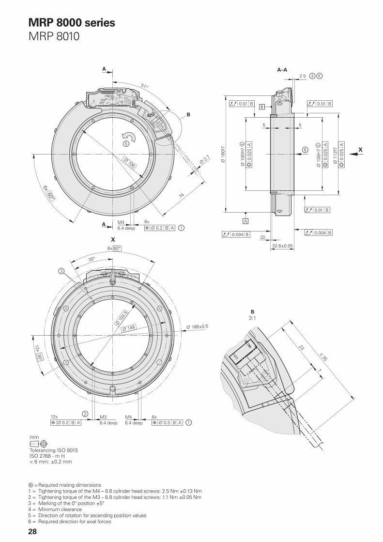
MRP 8000 seriesMRP 8010
Ⓚ = Required mating dimensions1 = Tightening torque of the M4 – 8.8 cylinder head screws: 2.5 Nm ±0.13 Nm2 = Tightening torque of the M3 – 8.8 cylinder head screws: 1.1 Nm ±0.05 Nm3 = Marking of the 0° position ±5°4 = Minimum clearance5 = Direction of rotation for ascending position values6 = Required direction for axial forces
29
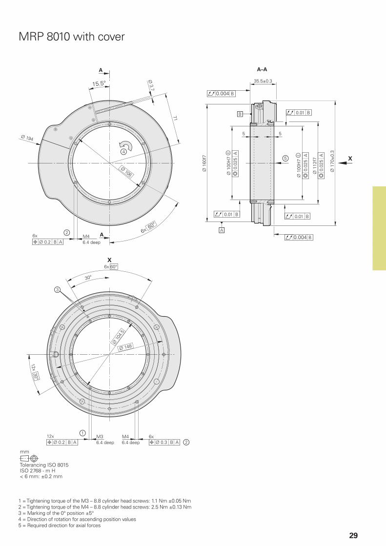
1 = Tightening torque of the M3 – 8.8 cylinder head screws: 1.1 Nm ±0.05 Nm2 = Tightening torque of the M4 – 8.8 cylinder head screws: 2.5 Nm ±0.13 Nm3 = Marking of the 0° position ±5°4 = Direction of rotation for ascending position values5 = Required direction for axial forces
MRP 8010 with cover
30
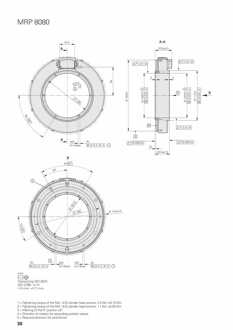
MRP 8080
1 = Tightening torque of the M4 – 8.8 cylinder head screws: 2.5 Nm ±0.13 Nm2 = Tightening torque of the M3 – 8.8 cylinder head screws: 1.1 Nm ±0.05 Nm3 = Marking of the 0° position ±5°4 = Direction of rotation for ascending position values5 = Required direction for axial forces
MRP 8010/MRP 8080
MRP 8010/MRP 8080
31
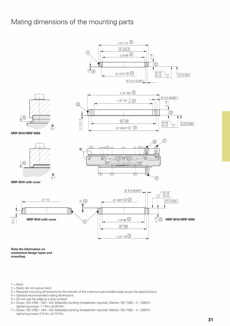
Mating dimensions of the mounting parts
1 = Rotor2 = Stator (do not use as rotor)3 = Required mounting dimensions for the transfer of the maximum permissible loads as per the specifications4 = Optional recommended mating dimensions5 = Do not use the edge as a stop surface!6 = Screw: ISO 4762 – M3 – 8.8. Materially bonding threadlocker required. Washer: ISO 7092 – 3 – 200HV;
tightening torque: 1.1 Nm ±0.05 Nm7 = Screw: ISO 4762 – M4 – 8.8. Materially bonding threadlocker required. Washer: ISO 7092 – 4 – 200HV;
tightening torque 2.5 Nm ±0.13 Nm
MRP 8010 with cover
MRP 8010 with cover
Note the information on mechanical design types and mounting.
SRP 5000
32
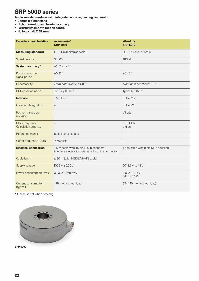
Encoder characteristics IncrementalSRP 5080
AbsoluteSRP 5010
Measuring standard OPTODUR circular scale DIADUR circular scale
Signal periods 30 000 16 384
System accuracy* ±2.5” or ±5”
Position error per signal period
±0.23” ±0.40”
Repeatability From both directions: 0.3” From both directions: 0.9”
RMS position noise Typically 0.007” Typically 0.020”
Interface » 1 VPP EnDat 2.2
Ordering designation – EnDat22
Position values per revolution
– 28 bits
Clock frequencyCalculation time tcal
– 16 MHz 5 µs
Reference marks 80 (distance-coded) –
Cutoff frequency –3 dB 500 kHz –
Electrical connection 1.5 m cable with 15-pin D-sub connector; interface electronics integrated into the connector
1.5 m cable with 8-pin M12 coupling
Cable length 30 m (with HEIDENHAIN cable)
Supply voltage DC 5 V ±0.25 V DC 3.6 V to 14 V
Power consumption (max.) 5.25 V: 950 mW 3.6 V: 1.1 W 14 V: 1.3 W
Current consumption (typical)
175 mA (without load) 5 V: 140 mA (without load)
* Please select when ordering
SRP 5000 seriesAngle encoder modules with integrated encoder, bearing, and motor• Compact dimensions• High measuring and bearing accuracy• Particularly smooth motion control• Hollow shaft ¬ 32 mm

2.700
1.569
0.385
0.128
0.00
0.50
1.00
1.50
2.00
2.50
3.00
0 50 100 150 200 250 300
33
Mounting situationAll stated motor characteristics apply to the following mounting situation:• Ambient temperature: 20 °C• Coil temperature: 40 °C• Stator screwed to steel plate with the
following characteristics: – Total surface area: 0.016 m2
– Specific thermal capacity: 460 J/kgK (at 20 °C)
– Specific thermal conductivity: 30 W/mK (at 20 °C)
Speed in rpm
Torq
ue
[Nm
]
Peak torque
Rated torque
Torque characteristic at DC 48 V
34
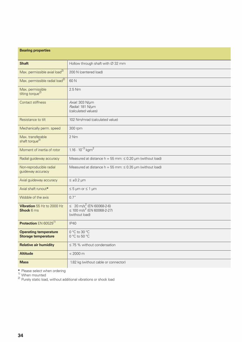
Bearing properties
Shaft Hollow through shaft with 32 mm
Max. permissible axial load2) 200 N (centered load)
Max. permissible radial load2) 60 N
Max. permissible tilting torque2)
2.5 Nm
Contact stiffness Axial: 303 N/µmRadial: 181 N/µm(calculated values)
Resistance to tilt 102 Nm/mrad (calculated value)
Mechanically perm. speed 300 rpm
Max. transferable shaft torque2)
2 Nm
Moment of inertia of rotor 1.16 · 10–3 kgm2
Radial guideway accuracy Measured at distance h = 55 mm: 0.20 µm (without load)
Non-reproducible radial guideway accuracy
Measured at distance h = 55 mm: 0.35 µm (without load)
Axial guideway accuracy ±0.2 µm
Axial shaft runout* 5 µm or 1 µm
Wobble of the axis 0.7”
Vibration 55 Hz to 2000 HzShock 6 ms
20 m/s2 (EN 60068-2-6) 100 m/s2 (EN 60068-2-27)(without load)
Protection EN 605291) IP40
Operating temperatureStorage temperature
0 °C to 30 °C0 °C to 50 °C
Relative air humidity 75 % without condensation
Altitude < 2000 m
Mass 1.82 kg (without cable or connector)
* Please select when ordering1) When mounted2) Purely static load, without additional vibrations or shock load
35
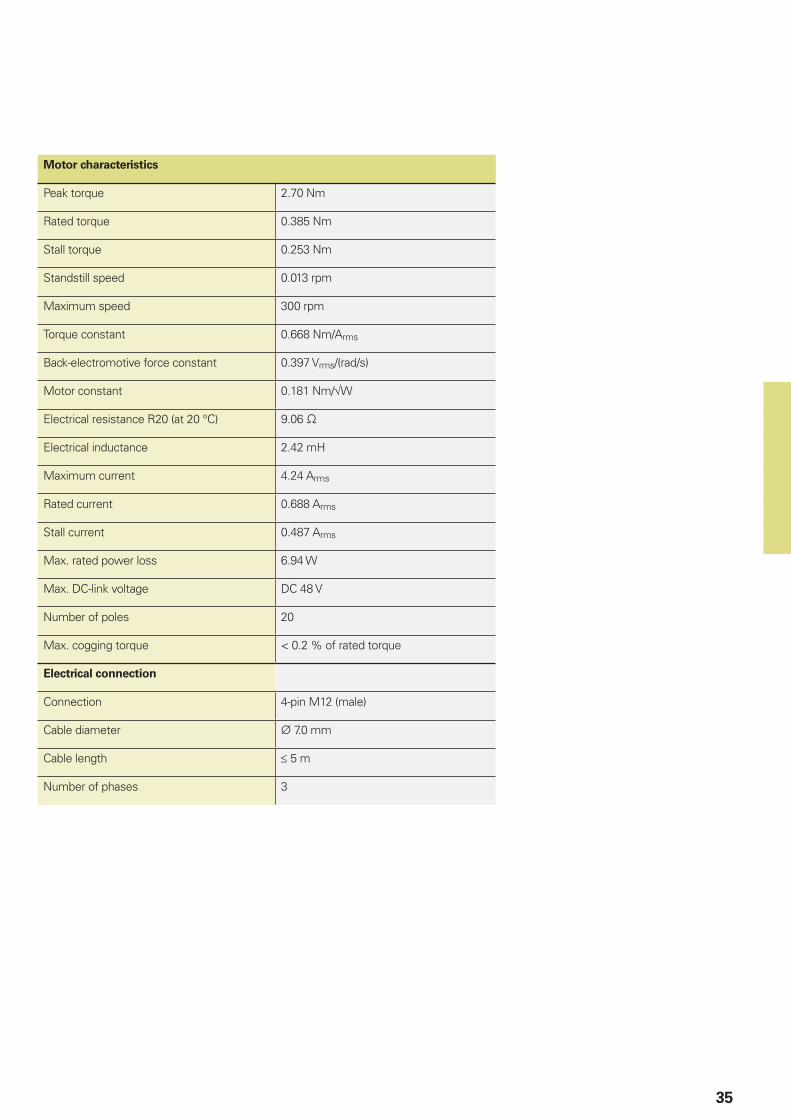
Motor characteristics
Peak torque 2.70 Nm
Rated torque 0.385 Nm
Stall torque 0.253 Nm
Standstill speed 0.013 rpm
Maximum speed 300 rpm
Torque constant 0.668 Nm/Arms
Back-electromotive force constant 0.397 Vrms/(rad/s)
Motor constant 0.181 Nm/√W
Electrical resistance R20 (at 20 °C) 9.06
Electrical inductance 2.42 mH
Maximum current 4.24 Arms
Rated current 0.688 Arms
Stall current 0.487 Arms
Max. rated power loss 6.94 W
Max. DC-link voltage DC 48 V
Number of poles 20
Max. cogging torque < 0.2 % of rated torque
Electrical connection
Connection 4-pin M12 (male)
Cable diameter 7.0 mm
Cable length ≤ 5 m
Number of phases 3
5
36
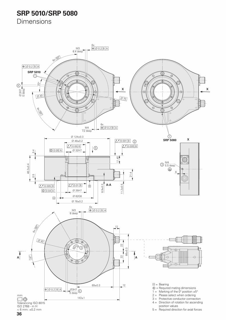
SRP 5010/SRP 5080Dimensions
A = BearingⓀ = Required mating dimensions1 = Marking of the 0° position ±5°2 = Please select when ordering3 = Protective conductor connection4 = Direction of rotation for ascending
position values5 = Required direction for axial forces

37
Dimensions of the connecting elements
Required mating dimensions
3 = Rotor4 = Stator5 = Screw: ISO 4762 – M3 – 8.8. Materially bonding threadlocker required. Washer: ISO 7092 – 3 – 200HV; tightening torque 1.1 Nm±0.05 Nm6 = Screw: ISO 4762 – M4 – 8.8. Materially bonding threadlocker required. Washer: ISO 7092 – 4 – 200HV; tightening torque: 2.5 Nm ±0.13 Nm7 = Required mating dimensions for the transfer of the maximum permissible load as per the specifications8 = Optional recommended customer dimensions
38
AccurET Modular 48
AccurET VHP 48
AccurET Modular 48 AccurET VHP 48
DC-link voltage DC 48 V
Number of axes 2
RMS continuous current 2.5 A 5 A 1.5 A 5 A
RMS peak current 5 A 10 A 3 A 10 A
Supply voltage DC 15 V to 48 V
RMS current consumption 10 A
PWM frequency 10 kHz, 20 kHz –
Encoder input 1 VPP (2048-fold interpolation)TTLEnDat 2.1 and EnDat 2.2
1VPP (up to 65 536-fold interpolation)TTLEnDat 2.1 and EnDat 2.2
Interfaces USB 2.0 (for configuration)ETEL real-time busEthernet (TCP/IP)
Digital I/O 4/2 per axis 4/4 per axis
Fast digital I/O 6/4 for both axes
Analog I/O With additional expansion board 4/4 for both axes
AccurET position controllers

14
39
Pin layout15-pin D-sub connector
14-pin PCB connector
Power supply Incremental signals Other signals
4 12 2 10 1 9 3 11 14 7 5/6/8/15 13 /
1b 7a 5b 3a 6b 2a 3b 5a 4b 4a / / /
UP SensorUP
0 V Sensor0 V
A+ A– B+ B– R+ R– Vacant Vacant Vacant
Brown/Green
Blue White/Green
White Brown Green Gray Pink Red Black / Violet Yellow
Cable shield connected to housing; UP = Power supply voltageSensor: The sense line is connected in the encoder with the corresponding power line.Vacant pins or wires must not be used!
Signal period360° elec.
(rated value)
A, B, R measured with oscilloscope in differential mode
Interfaces» 1 VPP incremental signals
HEIDENHAIN encoders with the » 1 VPP interface provide voltage signals that can be highly interpolated.
The sinusoidal incremental signals A and B are phase-shifted by 90° elec. and have amplitudes of typically 1 VPP. The illustrated sequence of output signals—with B lagging A—applies to the direction of motion shown in the dimension drawing.
The reference mark signal R has an unambiguous assignment to the incremental signals. The output signal may be lower next to the reference mark.
Alternative signal shape
Further information:
Comprehensive descriptions of all available interfaces as well as general electrical information can be found in the Interfaces of HEIDENHAIN Encoders brochure.

12 15
12
15
M12
40
Pin layout8-pin M12 coupling or flange socket
12-pin PCB connector
15-pin PCB connector
Power supply Position values
8 2 5 1 3 4 7 6
1b 6a 4b 3a 6b 1a 2b 5a
13 11 14 12 7 8 9 10
UP SensorUP
0 V Sensor0 V
DATA DATA CLOCK CLOCK
Brown/Green Blue White/Green White Gray Pink Violet Yellow
Cable shield connected to housing; UP = Power supply voltageSensor: The sense line is connected in the encoder with the corresponding power line.Vacant pins or wires must not be used!
Interfaces position values
The EnDat interface is a digital, bidirectional interface for encoders. It is able to output position values and read information stored in the encoder, as well as update this information or store new information. Thanks to the serial transmission method, only four signal lines are required. The DATA data are transmitted in synchronism with the CLOCK signal from the subsequent electronics. The type of transmission (position values, parameters, diagnostics, etc.) is selected via mode commands sent to the encoder by the subsequent electronics. Some functions are available only with EnDat 2.2 mode commands.
Ordering designation Command set Incremental signals
EnDat01 EnDat 2.1 or EnDat 2.2
With
EnDat21 Without
EnDat02 EnDat 2.2 With
EnDat22 EnDat 2.2 Without
Versions of the EnDat interface
Absolute encoder Subsequent electronics
» 1 VPP A*)
» 1 VPP B*)
Operating parameters
Operating status
Parameters of the OEM
Parameters of the encoder manufacturer for
EnDat 2.1 EnDat 2.2
*) Depends on the device
Absolute position value En
Dat
inte
rfac
e
Incremental signals *)
Further information:
Comprehensive descriptions of all available interfaces as well as general electrical information can be found in the Interfaces of HEIDENHAIN Encoders brochure.

ID 1140842-xx
41
Pin layout
1 2 3 4
Phase 1 Phase 2 Phase 3 GND
1 2 3 4
Phase 1 Phase 2 Phase 3 GND
White Brown Green Yellow
InterfacesMotor
Angle encoder modules with integrated motor have a slotless iron-core permanent-magnet AC synchronours motor with three phases.
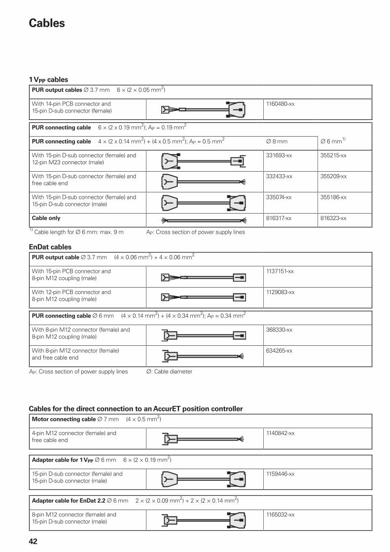
42
1 VPP cablesPUR output cables 3.7 mm 6 × (2 × 0.05 mm2)
With 14-pin PCB connector and 15-pin D-sub connector (female)
1160480-xx
PUR connecting cable 6 × (2 x 0.19 mm2); AP = 0.19 mm2
PUR connecting cable 4 × (2 x 0.14 mm2) + (4 x 0.5 mm2); AP = 0.5 mm2 8 mm 6 mm1)
With 15-pin D-sub connector (female) and 12-pin M23 connector (male)
331693-xx 355215-xx
With 15-pin D-sub connector (female) and free cable end
332433-xx 355209-xx
With 15-pin D-sub connector (female) and 15-pin D-sub connector (male)
335074-xx 355186-xx
Cable only 816317-xx 816323-xx
1) Cable length for 6 mm: max. 9 m AP: Cross section of power supply lines
Cables
EnDat cablesPUR output cable 3.7 mm (4 × 0.06 mm2) + 4 × 0.06 mm2
With 15-pin PCB connector and 8-pin M12 coupling (male)
1137151-xx
With 12-pin PCB connector and 8-pin M12 coupling (male)
1129083-xx
PUR connecting cable 6 mm (4 × 0.14 mm2) + (4 × 0.34 mm2); AP = 0.34 mm2
With 8-pin M12 connector (female) and 8-pin M12 coupling (male)
368330-xx
With 8-pin M12 connector (female) and free cable end
634265-xx
AP: Cross section of power supply lines : Cable diameter
Motor connecting cable 7 mm (4 × 0.5 mm2)
4-pin M12 connector (female) and free cable end
1140842-xx
Cables for the direct connection to an AccurET position controller
Adapter cable for 1 VPP 6 mm 6 × (2 × 0.19 mm2)
15-pin D-sub connector (female) and 15-pin D-sub connector (male)
1159446-xx
Adapter cable for EnDat 2.2 6 mm 2 × (2 × 0.09 mm2) + 2 × (2 × 0.14 mm2)
8-pin M12 connector (female) and 15-pin D-sub connector (male)
1165032-xx


PH MACHINEBANKS' CORPORATIONQuezon City, Philippines 1113 E-mail: [email protected]
PL APS02-384 Warszawa, Poland www.heidenhain.pl
PT FARRESA ELECTRÓNICA, LDA.4470 - 177 Maia, Portugal www.farresa.pt
RO HEIDENHAIN Reprezentanta RomaniaBrasov, 500407, Romania www.heidenhain.ro
RS Serbia BG
RU OOO HEIDENHAIN115172 Moscow, Russia www.heidenhain.ru
SE HEIDENHAIN Scandinavia AB12739 Skärholmen, Sweden www.heidenhain.se
SG HEIDENHAIN PACIFIC PTE LTDSingapore 408593 www.heidenhain.com.sg
SK KOPRETINA TN s.r.o.91101 Trencin, Slovakia www.kopretina.sk
SL NAVO d.o.o.2000 Maribor, Slovenia www.heidenhain.si
TH HEIDENHAIN (THAILAND) LTDBangkok 10250, Thailand www.heidenhain.co.th
TR T&M Mühendislik San. ve Tic. LTD. STI·.
34775 Y. Dudullu – Ümraniye-Istanbul, Turkey www.heidenhain.com.tr
TW HEIDENHAIN Co., Ltd.Taichung 40768, Taiwan R.O.C. www.heidenhain.com.tw
UA Gertner Service GmbH Büro Kiev 02094 Kiev, Ukraine www.heidenhain.ua
US HEIDENHAIN CORPORATIONSchaumburg, IL 60173-5337, USA www.heidenhain.com
VN AMS Co. LtdHCM City, VietnamE-mail: [email protected]
ZA MAFEMA SALES SERVICES C.C.Midrand 1685, South Africa www.heidenhain.co.za
ES FARRESA ELECTRONICA S.A.08028 Barcelona, Spain www.farresa.es
FI HEIDENHAIN Scandinavia AB01740 Vantaa, Finland www.heidenhain.fi
FR HEIDENHAIN FRANCE sarl92310 Sèvres, France www.heidenhain.fr
GB HEIDENHAIN (G.B.) LimitedBurgess Hill RH15 9RD, United Kingdom www.heidenhain.co.uk
GR MB Milionis Vassilis17341 Athens, Greece www.heidenhain.gr
HK HEIDENHAIN LTDKowloon, Hong Kong E-mail: [email protected]
HR Croatia SL
HU HEIDENHAIN Kereskedelmi Képviselet1239 Budapest, Hungary www.heidenhain.hu
ID PT Servitama Era ToolsindoJakarta 13930, Indonesia E-mail: [email protected]
IL NEUMO VARGUS MARKETING LTD.Holon, 58859, Israel E-mail: [email protected]
IN HEIDENHAIN Optics & Electronics India Private LimitedChetpet, Chennai 600 031, India www.heidenhain.in
IT HEIDENHAIN ITALIANA S.r.l.20128 Milano, Italy www.heidenhain.it
JP HEIDENHAIN K.K.Tokyo 102-0083, Japan www.heidenhain.co.jp
KR HEIDENHAIN Korea LTD.Gasan-Dong, Seoul, Korea 153-782 www.heidenhain.co.kr
MX HEIDENHAIN CORPORATION MEXICO20290 Aguascalientes, AGS., Mexico E-mail: [email protected]
MY ISOSERVE SDN. BHD.43200 Balakong, Selangor E-mail: [email protected]
NL HEIDENHAIN NEDERLAND B.V.6716 BM Ede, Netherlands www.heidenhain.nl
NO HEIDENHAIN Scandinavia AB7300 Orkanger, Norway www.heidenhain.no
NZ Llama ENGINEERING Ltd5012 Wellington, New Zealand E-mail: [email protected]
AR NAKASE SRL.B1653AOX Villa Ballester, Argentina www.heidenhain.com.ar
AT HEIDENHAIN Techn. Büro Österreich83301 Traunreut, Germany www.heidenhain.de
AU FCR MOTION TECHNOLOGY PTY LTDLaverton North Victoria 3026, Australia E-mail: [email protected]
BE HEIDENHAIN N.V.1760 Roosdaal, Belgium www.heidenhain.be
BG ESD Bulgaria Ltd.Sofia 1172, Bulgaria www.esd.bg
BR HEIDENHAIN Brasil Ltda.04763-070 – São Paulo – SP, Brazil www.heidenhain.com.br
BY GERTNER Service GmbH220026 Minsk, Belarus www.heidenhain.by
CA HEIDENHAIN CORPORATIONMississauga, OntarioL5T2N2, Canada www.heidenhain.com
CH HEIDENHAIN (SCHWEIZ) AG8603 Schwerzenbach, Switzerland www.heidenhain.ch
CN DR. JOHANNES HEIDENHAIN (CHINA) Co., Ltd.Beijing 101312, China www.heidenhain.com.cn
CZ HEIDENHAIN s.r.o.102 00 Praha 10, Czech Republic www.heidenhain.cz
DK TP TEKNIK A/S2670 Greve, Denmark www.tp-gruppen.dk
DE HEIDENHAIN Vertrieb Deutschland83301 Traunreut, Deutschland 08669 31-3132| 08669 32-3132E-Mail: [email protected]
HEIDENHAIN Technisches Büro Nord12681 Berlin, Deutschland 030 54705-240
HEIDENHAIN Technisches Büro Mitte07751 Jena, Deutschland 03641 4728-250
HEIDENHAIN Technisches Büro West44379 Dortmund, Deutschland 0231 618083-0
HEIDENHAIN Technisches Büro Südwest70771 Leinfelden-Echterdingen, Deutschland 0711 993395-0
HEIDENHAIN Technisches Büro Südost83301 Traunreut, Deutschland 08669 31-1337
Vollständige und weitere Adressen siehe www.heidenhain.de For complete and further addresses see www.heidenhain.de
����������������������������������������������������������� ���� ���������������� ����������� ��������� �����������������������������
����������������
*I1102713-23*
1102713-23 · 5 · 04/2019 · H · Printed in Germany


