237 AnInvestigation of Some Banded Structures Metal Crystals. By C. F. E lam, D.Sc ., with an appendix by Prof. G. I. Taylor, F.R.S. (Communicated by G. 1. Taylor, F.R.S.—Received August 28, 1928. [Plate 3.] Crystals of the native metals gold, silver and copper have been found which exhibit twinning on an octahedral plane of the spinel type. Metallurgists have described as twins the banded structures which are of very frequent occurrence in these metals when prepared commercially, as they resemble lamellar twinning in calcite and felspar very closely. A few quantitative measurements have been made to determine the relationship between such bands in a metallic crystal; but the value of the results depends on the correct determination of the orientation of the respective parts, and this can only be done by means of X-rays or by indirect methods such as the measurement of slip-bands, etching-pits, etc., which are not always trustworthy. McKeehan* measured some structures resembling twins in nearly pure iron by obtaining reflections from the deeply etched surface of a wire mounted in a goniometer. He concluded that the crystals were twins in a crystallo- graphic sense, the twin plane being of the form {211} and the twin axis of the form [111]. A. J. Phillipst made some measurements of the angles between more than one set of bands in the same crystal in specimens of copper and brass, and found that they were inclined at approximately 70° to each other. (The angle between octahedral planes of a cubic crystal is 70° 31'.) Similarly, he measured the inclinations of traces of secondary bands in the principal bands, and found that these also could be considered as being traces of octahedral planes in the bands, provided that the two were related to each other as the two parts of the spinel twin. From this he concluded that the bands were true twins. No direct measurements of the orientation of either the original crystal or of the bands were made, and in many cases the bands could not be traced over the edge between the two faces of the specimen, so that there was a certain amount of conjecture as to whether two traces really belonged to the same plane. In a letter to ‘ Nature ’J the present writer pointed out that banded * ‘ Amer. Inst. Mining Met. Eng.,’ September, 1927. t ‘ Amer. Inst. Mining Met. Eng.,’ February, 1927. t ‘ Nature,’ vol. 120, p. 259 (1927). on September 2, 2018 http://rspa.royalsocietypublishing.org/ Downloaded from
Transcript
237
An Investigation of Some Banded Structures Metal Crystals.By C. F. E lam, D.Sc., with an appendix by Prof. G. I. Taylor, F.R.S.
(Communicated by G. 1. Taylor, F.R.S.—Received August 28, 1928.
[Plate 3.]
Crystals of the native metals gold, silver and copper have been found which exhibit twinning on an octahedral plane of the spinel type. Metallurgists have described as twins the banded structures which are of very frequent occurrence in these metals when prepared commercially, as they resemble lamellar twinning in calcite and felspar very closely. A few quantitative measurements have been made to determine the relationship between such bands in a metallic crystal; but the value of the results depends on the correct determination of the orientation of the respective parts, and this can only be done by means of X-rays or by indirect methods such as the measurement of slip-bands, etching-pits, etc., which are not always trustworthy.
McKeehan* measured some structures resembling twins in nearly pure iron by obtaining reflections from the deeply etched surface of a wire mounted in a goniometer. He concluded that the crystals were twins in a crystallographic sense, the twin plane being of the form {211} and the twin axis of the form [111].
A. J. Phillipst made some measurements of the angles between more than one set of bands in the same crystal in specimens of copper and brass, and found that they were inclined at approximately 70° to each other. (The angle between octahedral planes of a cubic crystal is 70° 31'.) Similarly, he measured the inclinations of traces of secondary bands in the principal bands, and found that these also could be considered as being traces of octahedral planes in the bands, provided that the two were related to each other as the two parts of the spinel twin. From this he concluded that the bands were true twins. No direct measurements of the orientation of either the original crystal or of the bands were made, and in many cases the bands could not be traced over the edge between the two faces of the specimen, so that there was a certain amount of conjecture as to whether two traces really belonged to the same plane.
In a letter to ‘ Nature ’J the present writer pointed out that banded* ‘ Amer. Inst. Mining Met. Eng.,’ September, 1927. t ‘ Amer. Inst. Mining Met. Eng.,’ February, 1927. t ‘ Nature,’ vol. 120, p. 259 (1927).
on September 2, 2018http://rspa.royalsocietypublishing.org/Downloaded from
structures in aluminium and copper liad been obtained which resembled twins in appearance, but which did not have the correct relationship for norma! twins. Also, in a paper describing some experiments with crystals of a copper- aluminium alloy,* two examples were given of twin-like structures. One could be described as parallel growth, part of the crystal being rotated 7° with regard to the other about a common axis. The other was the result of distortion. The crystal was so oriented that the shear stress was nearly equal on two octahedral planes and one part slipped on one plane and one on the other.
Some measurements have now been made in order to obtain further information about these structures, and to determine their true nature with greater accuracy than before.
The most complete measurements have been made on some samples of aluminium that contained exceptionally large bands. Although aluminium has the same crystal structure as copper, silver and gold (face-centred cubic), the crystals are rarely founded with a banded structure after treatment which would normally produce it. When, however, a large aluminium crystal is strained about 10 per cent, and heated until it recrystallises, the new crystals
have very straight boundaries, and some of these take on the typical banded structure of twinned copper.
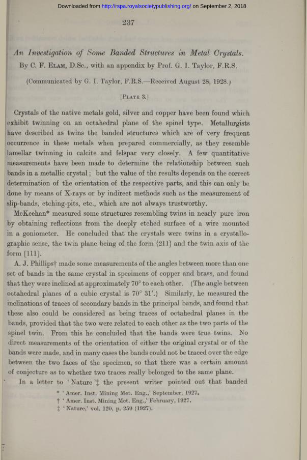
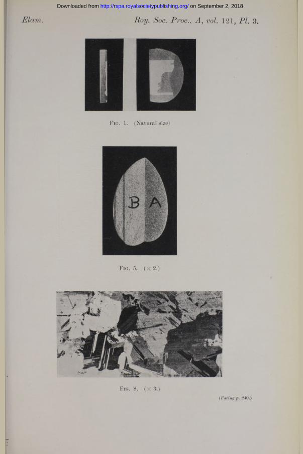
Two examples with very clear banding were chosen and the orientation of each part relative to the surface determined by means of X-rays. The inclinations of the bands on two surfaces were also measured so that the plane of intersection between the bands and the original crystal could be compared with the X-ray measurements. Fig. 1 (Plate 3) is a photograph showing two sides at right angles, and fig. 2 a diagram of one crystal cut from a sheet
ig. 2. Diagram of Crystal, i thick. The principal crystal went throughthe sheet, but the twin did not, as the photo
graph shows. Further, although the junction between the two parts on one face was straight, on the other it was uneven and like an ordinary crystal boundary. It was not possible to obtain any trustworthy measurements of the inclination of the line of intersection on this face. Particulars of the
* ‘ Roy. Soc. Proc.,’ A, vol. 116, p. 694 (1927).
FACE
s\\^\\\\\V\\^a
on September 2, 2018http://rspa.royalsocietypublishing.org/Downloaded from
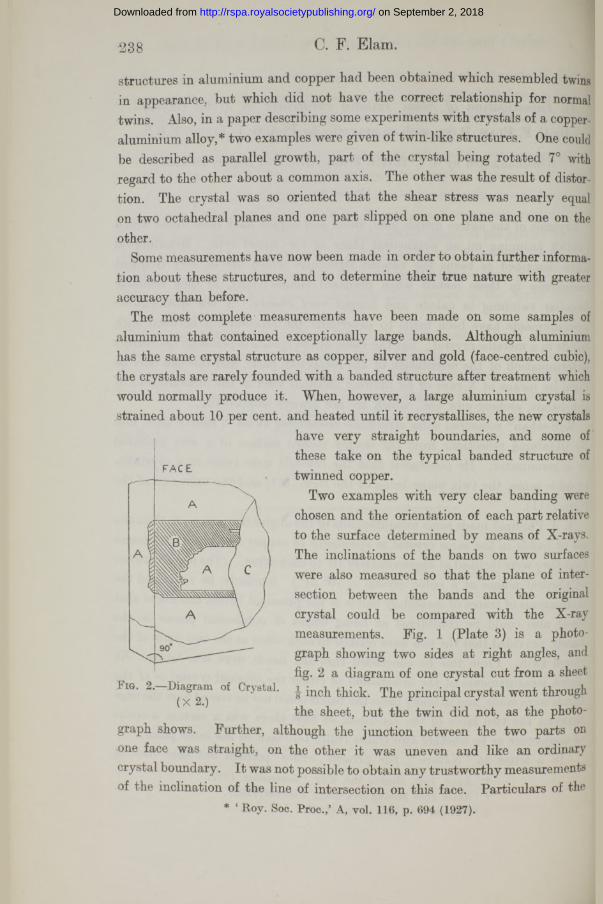
X-ray data are given in Table I. and are plotted on a stereographic diagram in fig. 3. The plane of the paper represents the face of the specimen and the
Table I.—Reference Plane = Face of Specimen.6 as Angle between normal to plane and line of intersection of face and edge.tp = Angle between plane containing the normal of the reflecting plane and face of
specimen, measured anti-clockwise.
Reflecting Planes. Twin Plane.
1k ;=115° 9 = 136° 9 = 157° 30'! 7° II 2 o •A = 359° 30'
1 86° e = 123° 9 = 156°
rw II
II
1 8° II Ci t/s= 0°
r a / * = 83° 10' e = 57° 30' 9 = 153° 308° 30' tp= 81° xjj = 14°
.2. w II II 99° 30' 9 = 42° 10' 9 = 154° 30'
<9° tjs = 5° 30' «A= 14° 30
Plane of intersection of A and B, 9 = 148° 30'ifj = 14° 30'
T o p
Wig . 3.—A1 Twin I. Face of specimen represented by plane of paper. L = Normalto Face. T = Twin Plane.
vertical line corresponds to the line of intersection of the section with the face. Only the poles of those planes lying on the upper hemisphere are marked and the indices of those of crystal B are in brackets to distinguish them from crystal A. I t will be seen th a t both crystals have an octahedral plane, 111 .and (111) in the diagram marked T, in the same position. This plane has been drawn in the diagram, and it will be seen tha t it cuts the circumference at 90
on September 2, 2018http://rspa.royalsocietypublishing.org/Downloaded from
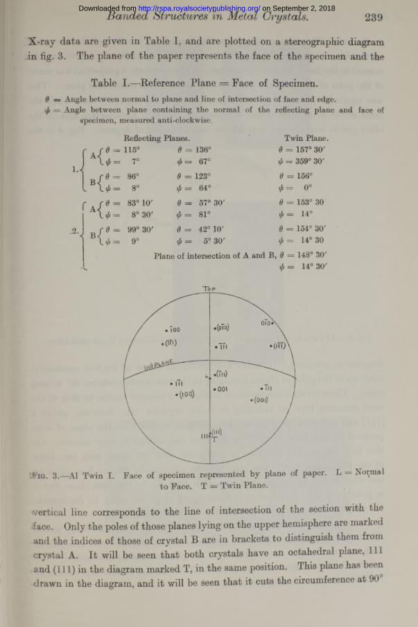
to the axis. This agrees with the inclination of the junction of the two parts on the face of the specimen. The centre of the projection L represents the normal to the face. In order to compare the two crystals, a projection was made of the poles of all the other planes on to the common octahedral plane. This was equivalent to rotating the figure—using a stereographic net—until the poles of the octahedral planes occupied the centre of the diagram and all the other points were moved through the same number of degrees. Fig. 4 is the
Fig. 4.—A1 Twin I. Projection of both crystals on to Common Octahedral Plane.
diagram so obtained. It shows a symmetrical figure of six-fold symmetry,, made up of the poles of planes belonging to the two crystals rotated 60° to each, other. These crystals are therefore related in a manner similar to that of the most common type of twinning in cubic crystals, viz., rotation about a [111] axis and on a {ill} plane. I t is difficult to determine the plane of composition of this twin as the boundary on one section is very uneven. On this face the general direction of the plane does not agree with the trace of the twin plane, but it has been pointed out already that it does agree on the other face. The plane of composition need not be the twin plane, but it is possible that in this case it is made up of steps too small to distinguish, the majority of which agree in direction with this plane.
Another specimen was measured in the same way with the same result. The twin crystals penetrated the sheet and the boundaries were straight on both sections, so that the inclination of the planes could be determined. The results of all measurements are given in Table I, but as this crystal was so similar to the first no diagrams are given.
on September 2, 2018http://rspa.royalsocietypublishing.org/Downloaded from
These crystals, therefore, fulfil all the requirements for true crystallographic twinning, and it has thus been established that twins occur in aluminium, although rarely.
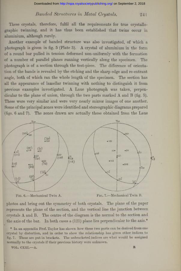
Another example of banded structure was also investigated, of which a photograph is given in fig. 5 (Plate 3). A crystal of aluminium in the form of a round bar pulled in tension deformed non-uniformly with the formation of a number of parallel planes running vertically along the specimen. The photograph is of a section through the test-piece. The difference of orientation of the bands is revealed by the etching and the sharp edge and re-entrant angle, both of which ran the whole length of the specimen. The section has all the appearance of lamellar twinning with nothing to distinguish it from previous examples investigated. A Laue photograph was taken, perpendicular to the plane of union, through the two parts marked A and B (fig. 5). These were very similar and were very nearly mirror images of one another. Some of the principal zones were identified and stereographic diagrams prepared (figs. 6 and 7). The zones drawn are actually those obtained from the Laue
Banded Structures Metal Crystals. 24 L
F ig. 7.—Mechanical Twin B.Fig. 6.—Mechanical Twin A.
photos and bring out the symmetry of both crystals. The plane of the paper represents the plane of the section, and the vertical line the junction between crystals A and B. The centre of the diagram is the normal to the section and the axis of the bar. In both cases a (121) plane lies perpendicular to the axis.*
* In an appendix Prof. Taylor has shown how these two parts can be derived from one crystal by distortion, and in order to show the relationship has given other indices to fig. 7. These are put in brackets. The unbracketed indices are what would be assigned normally to the crystals if their previous history were unknown.
VOL. CXXI.— A. R
on September 2, 2018http://rspa.royalsocietypublishing.org/Downloaded from
It has already been shown that when an aluminium crystal is distorted in tension, the final position of the crystal axes is such that the pole of a {112} plane coincides with the axis of the specimen, and two octahedral planes, the slip planes, make equal angles with the axis. This condition has been fulfilled in both parts of the crystal, so that both are identical with regard to the vertical axis. They are also related in such a manner that the two are mirror images of each other about their plane of union, the vertical plane represented by a straight line in both figures. They are also mirror images of each other in the (121) plane which they have in common. The one can be derived from the other by a rotation of 66° about an axis normal to the (121) plane. The point P on the circumference is the pole of the plane of intersection of the two crystals. The nearest crystallographic plane in both has the indices {113}, so that the specimen as a whole can be considered as a reflection twin about this plane. I t is very different from the other samples already described, and the explanation must be sought in the method of production. In this respect it resembles the copper-aluminium crystal already referred to, and it is probable that here also the costal was in such a position that slip occurred on different planes in different parts, but the original position of the axes is unknown. I t is certain, however, that if this structure can be called a twin it is of a different kind from those produced during recrystallisation after mechanical and heat treatment. I t is interesting to compare the similar but opposite observations with zinc. Mathewson and Phillips* showed that there is good reason to think that the banding produced by mechanical deformation of zinc is the result of twinning. Twinning in annealed zinc, however, has never been observed.
I t has already been mentioned that banded structures, commonly described as twin crystals, are always found in copper, silver and gold which has been heated after being mechanically deformed. The twins so produced are generally small and frequently themselves contain twin bands. A piece of native copper was obtained which had relatively large simple twins, so that X-ray photographs could be taken of each part of the twin. There did not appear to be any relation between the parts, as was mentioned in the letter to ‘ Nature,' but it was subsequently found that the metal may have been distorted, so that these observations are not reliable. Later, a strip of silver was obtained tV inch thick, in which the crystals were large, and in some of these the twins were relatively simple and larger than usual. A photograph is shown in fig* 8, Plate 3. Even here it was extremely difficult to find examples in which
* ‘ Amer. Inst. Mining Met. Eng.’ (1927).
on September 2, 2018http://rspa.royalsocietypublishing.org/Downloaded from
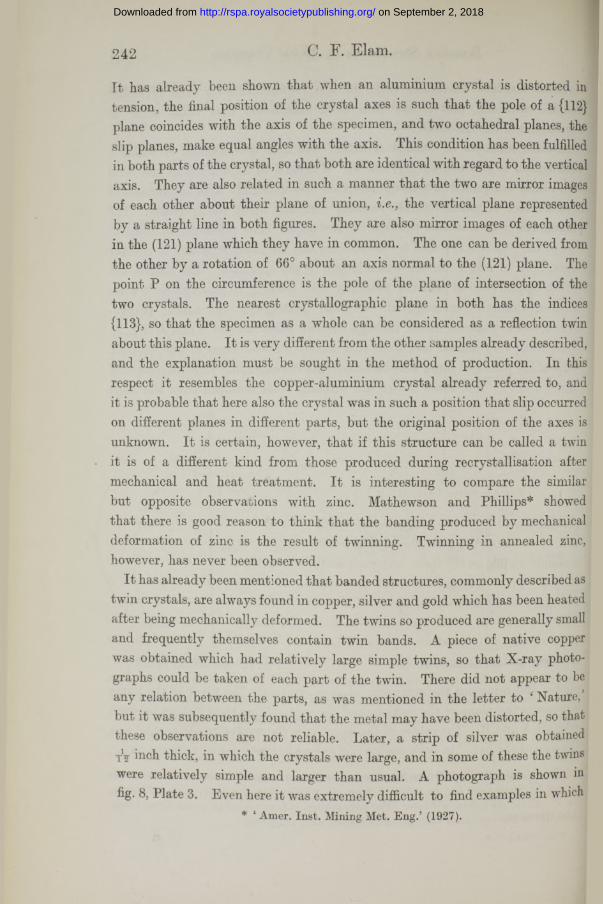
the twin bands could be traced on both the face and edge of the specimens and in which they were sufficiently wide to give reliable X-ray reflections. Owing to the fact that the bands were narrow and frequently intersected by similar smaller bands, no reliable data were obtained for fixing their orientation with regard to the main crystal. This has had to be abandoned until more suitable samples can be procured. In one case the orientation of the principal crystal was determined, however, and correlated with the traces of three twin planes. A diagrammatic drawing is given in fig. 9. The traces of two
planes, B and C, were clearly visible on the face and section of the specimen and on the opposite side, the crystal penetrating the strip ; that of the third was only visible on the faces, but was parallel to the edge, and it was concluded that the plane was parallel with the section. A stereographic diagram was therefore made embodying the results of these and the X-ray measurements. The observations of the traces of the planes are marked with a circle. The poles of the four octahedral planes determined from X-ray photographs are marked, and the traces of three of these drawn. These two sets of measurements agree within the limits of experimental error. I t is considered, therefore, that these bands follow the octahedral planes of the crystal in which they occur, but it has not yet been proved that the material within the bands bears a twinned relationship to the original crystal. I t is highly probable that this is so, as Phillips concluded from his observations, but it has been shown above that apparently similar structures may or may not be considered as simple twins, and only a complete analysis of the crystal orientations can decide the question.
Fig. 9.—Silver Twin. ( x 4.) Fig. 10.
on September 2, 2018http://rspa.royalsocietypublishing.org/Downloaded from
It has been shown that aluminium can form twins of the spinel type, although this metal has been generally considered to be the exception amongst others of the same crystal structure to forming such twins. The plane of composition can be the twin plane, but it is not always so, as the one example illustrated shows. In this case the two components were united in one plane by a ragged boundary, indistinguishable from an ordinary crystal boundary, and this suggests the possibility that twins may be more common than appears, but that they are overlooked because they are not united along the twin plane i.e., they do not exhibit straight boundaries.
There are also similar structures, i.ebanding with straight boundaries, which are not of the spinel type of twin. The plane of composition in one example investigated had indices {113}, and the crystal can be considered as a reflection twin in this plane. This can be described as “ mechanical twinning/’ Another type of banding found in the aluminium-bronze crystal referred to previously--which was only one example of many—may be more truly described as parallel growth.
This work was carried out at the Royal School of Mines, in the laboratory of Prof. H. C. H. Carpenter, F.R.S., to whom I wish to express my thanks.
A p p e n d ix .
By G. I. Taylor , F.R.S.It is of interest to trace the connection between the known manner in which
aluminium crystals are distorted under tensile stress and the formation of the “ mechanical twins ” discussed by Dr. Elam. As she points out, “ mechanical twins ” are likely to be found when two possible planes of slip are equally inclined to the axis of the specimen. There are two ways in which this condition may be satisfied. The axis of the specimen may lie (a) in an octahedral plane, ( b) in a cubic plane. In case (a) slipping on one of the possible slip planes brings the other plane into such a position that the component of shear stress is greater on the second than it is on the first. This tends to make the material slip on the second plane and stop slipping on the first, thus giving rise to equal double slipping throughout the material.
In case (6), on the other hand, slip on one of the two possible slip planes increases the component of shear stress on the second plane above that on the first, so that slipping tends to proceed on whichever of the two planes it began. When slipping begins on different planes in different parts of the same
on September 2, 2018http://rspa.royalsocietypublishing.org/Downloaded from
specimen, it can only continue in this way provided that neighbouring parts in which the slipping is on two different planes continue to fit together as distortion proceeds. If the slipping in the two neighbouring parts is confined to one plane in each part, this condition can only be satisfied if (1) the surface of separation is a plane which contains the axis of the specimen, (2) the crystal axes on the two sides are in the position of mirror images in this plane, (3) the amount of slipping is equal in the two parts.
Dr. Elam has shown by means of the microphotograph, fig. 6, and her X-ray analysis that conditions (1) and (2) are satisfied. I t seems certain that condition (3) is also satisfied, for the two parts into which the specimen was divided, both stretched through the same amount.
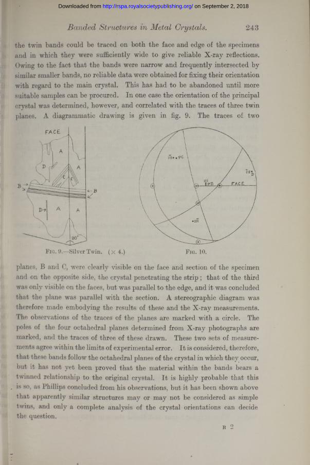
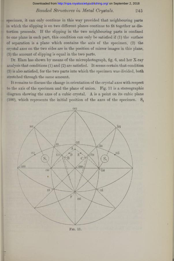
It remains to discuss the change in orientation of the crystal axes with respect to the axis of the specimen and the plane of union. Fig. 11 is a stereographic diagram showing the axes of a cubic crystal. A is a point on its cubic plane (100), which represents the initial position of the axes of the specimen. Sx
001
^100
Fig. 11.
on September 2, 2018http://rspa.royalsocietypublishing.org/Downloaded from
and S2 are the two possible slip planes whose poles are shown a t (111) and (111) respectively. The directions of slip are the normals (110) on Sx and (IlO) on S2.
As slipping proceeds the direction of the axis of the specimen moves relatively to the crystal axes in the direction AB in one part of the specimen and AC in the other. At any given extension, say, 30 per cent., the two points representing the axis of the specimen in the two parts will move to D and E respectively where AD equals AE.
As slipping proceeds the points representing the axis of the specimen move along great circles towards the poles of the planes (110) and (IlO) till they reach the points B and C, where these great circles cut the dodecahedral planes (101) and (101). At this stage double slipping begins in each part into which the specimen is divided and the points representing the axis of the specimen move very slowly towards the poles of the planes (121) and (121).
The amount of extension which the specimen sustains before the double slipping begins depends on the position of the point A. Its maximum value is 73 per cent, when A coincides with the pole (Oil). Referring to Dr. Elam’s diagram figs. 7 and 8, it will be seen th a t a t the stage a t which her X-ray analysis was carried out, the axis of the specimen was very close to the normal to the plane (121) in one part and (121) in the other. I t is improbable tha t the total extension of the specimen was much greater than 70 per cent, (though it was not measured). Consequently, i t seems likely tha t A was close to the pole (011) as is shown in the diagram, fig. 10.
At the beginning of the test the plane of union of the two layers of the specimen must in any case have been parallel to the cubic plane (100). The line of particles represented by E (fig. 11), which lie along the normal to the plane (Oil), is in the plane of junction and also in both slip planes Sx and S2, so that this plane of particles remains normal to the plane (Oil) in both parts of the specimen as the specimen extends. The plane of union passes through this normal and through the axis of the specimen. At the moment when double slipping begins therefore, the plane of union is represented by the dotted circle BF in one part and the circle CF in the other.
Since the point A is close to the pole (Oil) and the point B therefore close to the pole (121), the plane of junction nearly coincided with the plane passing through the poles (121) and (Oil) a t the time the double slipping began in both parts of the specimen. This plane, which is represented by indices (113), is marked in fig. 11. The corresponding plane for the other part of the specimen is that passing through the poles (121) and (Oil). These are in fact the orientations which Dr. Elam finds by X-ray analysis.
on September 2, 2018http://rspa.royalsocietypublishing.org/Downloaded from
It appears, therefore, that if the laws previously discovered regarding the distortion of aluminium crystals are applied to the case of a tensile specimen whose longitudinal axis lies in a cubic crystal plane and close to the normal to an octahedral plane, “ mechanical twins ” of the type discovered by Dr. Elam might have been predicted as possible, and the orientation of the two sets of crystal axes would bear the same relationship to the plane of union and the longitudinal axis of the specimen as that actually found.
Change in Lattice Spacing at Crystal 247
The Change in Lattice Spacing at a Crystal Boundary.By J. E. L e n n a r d -Jones and B eryl M. D en t , The University, Bristol.
(Communicated by S. Chapman, F.R.S.—Received April 27, 1928.)
§ 1. Introduction.Some recent experiments of Davisson and Germer* on the scattering of
electrons by a crystal have drawn attention to the conditions at a crystal boundary. In interpreting their results in terms of de Broglie waves, the authors have to postulate a contraction of the crystal lattice at the surface— in some cases of as much as 30 per cent.f I t is, therefore, important that other independent methods should be devised to indicate what change (if any) takes place at a crystal surface. Unfortunately X-rays are unable to help in this respect as several hundred atomic layers are necessary to produce a Bragg reflection pattern ; nor is theory able to provide an answer in the case of metallic crystals such as are used by Davisson and Germer because little is known of the forces which hold a metal together. Certain other cases can, however, be considered theoretically, and these may indicate the order of the effect to be expected in metallic crystals.
In this paper we consider the change in spacing at a (100) boundary of a crystal of the NaCl type, this boundary being considered because it is a natural plane of crystal. Two effects are to be anticipated : (1) a change of spacing between planes at the boundary; (ii) a change of spacing between atoms in
* Davisson and Germer, ‘ Nature,’ vol. 119, p. 558 (1927); ‘ Phys. Rev.,’ vol. 30, p. 705 (1927). The experiments of G. P. Thomson (‘ Roy. Soc. Proc.,’ A, vol. 117, p. 600 (1928) ) are not affected in the same way by surface conditions owing to the high speed of the electrons.
t See note at end of paper.
on September 2, 2018http://rspa.royalsocietypublishing.org/Downloaded from