The speckle pattern observed in the light beam re-flected from an object is caused by random interferencebetween light waves scattered from different points onthe object surface. A number of techniques have beenreported on the utilization of this speckle pattern formeasuring surface displacement.1–4 For example, inthe method commonly referred to as speckle photogra-phy the light beam reflected from the object surface isrecorded on photographic film with a CCD camera be-fore and after displacement. The Fourier transformof the double record is modulated by interferencefringes that are perpendicular to the direction of dis-placement. The fringe pitch is directly related to thedisplacement of the object between the two exposures.The fringe system can be obtained only when the dis-tance between identical speckles in the double record isgreater than the diameter of each speckle. The small-est displacement of the object that can be measuredusing speckle photography is equal to the diameter g ofspeckles that emerge from the object. Therefore, ac-curate knowledge of this quantity is of fundamentalimportance in speckle metrology. The classicalvalue1–4 for the speckle diameter in the far field of aflat substrate with a rough surface is g 5 1.2lLyD,where l, L, D are, respectively, the laser wavelength,the distance from the object to the observation plane,and the diameter of the light spot on the object surface.Our aim is to emphasize the joint influence of both the
The authors are with the Departamento de Fisica, UniversidadSimon Bolivar, Caracas 1080-A, Venezuela.
Received 27 November 1995; revised manuscript received 13December 1996.
surface roughness and the surface curvature on theshape and linear dimensions of light speckles. A fun-damental conclusion of the study outlined in the fol-lowing sections is that light speckles have differentdimensions in different directions when the object hasanisotropic curvature and roughness. Consequently,displacement of objects with arbitrary curvature androughness can be measured with a resolution that de-pends on the direction of displacement. The case of aflat surface is discussed in Section 2. We show thatthe light speckles are enlarged with respect to theclassical value g given above ~although still maintain-ing an approximately round shape! when the observa-tion plane is positioned in the neighborhood of theobject surface and the surface is smooth. As demon-strated in Section 3, for a curved surface light specklesare lengthened in a preferential direction even for ob-servation planes placed in the far field and for commonvalues of surface roughness. We present experimen-tal results in Section 4. Comparison between the the-oretical analysis and experimental results is made inSection 5. General conclusions are discussed in Sec-tion 6. References 1–4 outline general methods ofspeckle metrology. References 5–14 deal with the re-lation between statistical properties of a rough surfaceand the corresponding properties of the scattered lightfield. The special case of rough surfaces on a cylin-drical substrate was studied in Refs. 15–18. Of spe-cial relevance for the subject covered in this paper areRefs. 19 and 20 that deal with metrological applica-tions of speckle patterns to measurements of strainand torque on cylindrical objects.
2. Speckle Patterns in the Light Scattered by a FlatObject
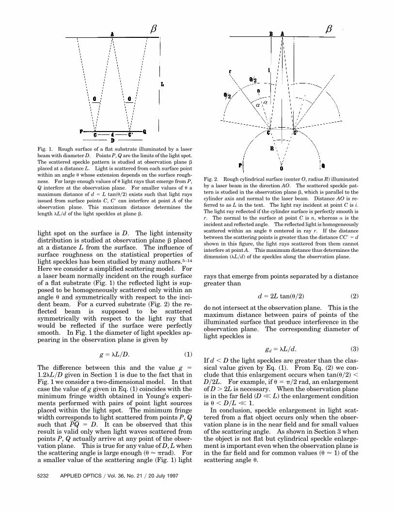
Figure 1 represents a flat object with a rough surfaceilluminated by a laser beam. The diameter of the
20 July 1997 y Vol. 36, No. 21 y APPLIED OPTICS 5231
light spot on the surface is D. The light intensitydistribution is studied at observation plane b placedat a distance L from the surface. The influence ofsurface roughness on the statistical properties oflight speckles has been studied by many authors.5–14
Here we consider a simplified scattering model. Fora laser beam normally incident on the rough surfaceof a flat substrate ~Fig. 1! the reflected light is sup-posed to be homogeneously scattered only within anangle u and symmetrically with respect to the inci-dent beam. For a curved substrate ~Fig. 2! the re-flected beam is supposed to be scatteredsymmetrically with respect to the light ray thatwould be reflected if the surface were perfectlysmooth. In Fig. 1 the diameter of light speckles ap-pearing in the observation plane is given by
g 5 lLyD. (1)
The difference between this and the value g 51.2lLyD given in Section 1 is due to the fact that inFig. 1 we consider a two-dimensional model. In thatcase the value of g given in Eq. ~1! coincides with theminimum fringe width obtained in Young’s experi-ments performed with pairs of point light sourcesplaced within the light spot. The minimum fringewidth corresponds to light scattered from points P, Qsuch that PQ 5 D. It can be observed that thisresult is valid only when light waves scattered frompoints P, Q actually arrive at any point of the obser-vation plane. This is true for any value of D, L whenthe scattering angle is large enough ~u ' prad!. Fora smaller value of the scattering angle ~Fig. 1! light
Fig. 1. Rough surface of a flat substrate illuminated by a laserbeam with diameter D. Points P, Q are the limits of the light spot.The scattered speckle pattern is studied at observation plane bplaced at a distance L. Light is scattered from each surface pointwithin an angle u whose extension depends on the surface rough-ness. For large enough values of u light rays that emerge from P,Q interfere at the observation plane. For smaller values of u amaximum distance of d 5 L tan~uy2! exists such that light raysissued from surface points C, C9 can interfere at point A of theobservation plane. This maximum distance determines thelength lLyd of the light speckles at plane b.
5232 APPLIED OPTICS y Vol. 36, No. 21 y 20 July 1997
rays that emerge from points separated by a distancegreater than
d 5 2L tan~uy2! (2)
do not intersect at the observation plane. This is themaximum distance between pairs of points of theilluminated surface that produce interference in theobservation plane. The corresponding diameter oflight speckles is
gd 5 lLyd. (3)
If d , D the light speckles are greater than the clas-sical value given by Eq. ~1!. From Eq. ~2! we con-clude that this enlargement occurs when tan~uy2! ,Dy2L. For example, if u 5 py2 rad, an enlargementof D . 2L is necessary. When the observation planeis in the far field ~D ,, L! the enlargement conditionis u , DyL ,, 1.
In conclusion, speckle enlargement in light scat-tered from a flat object occurs only when the obser-vation plane is in the near field and for small valuesof the scattering angle. As shown in Section 3 whenthe object is not flat but cylindrical speckle enlarge-ment is important even when the observation plane isin the far field and for common values ~u ' 1! of thescattering angle u.
Fig. 2. Rough cylindrical surface ~center O, radius R! illuminatedby a laser beam in the direction AO. The scattered speckle pat-tern is studied in the observation plane b, which is parallel to thecylinder axis and normal to the laser beam. Distance AO is re-ferred to as L in the text. The light ray incident at point C is i.The light ray reflected if the cylinder surface is perfectly smooth isr. The normal to the surface at point C is n, whereas a is theincident and reflected angle. The reflected light is homogeneouslyscattered within an angle u centered in ray r. If the distancebetween the scattering points is greater than the distance CC9 5 dshown in this figure, the light rays scattered from them cannotinterfere at point A. This maximum distance thus determines thedimension ~lLyd! of the speckles along the observation plane.
3. Speckles in Light Scattered by a Cylindrical Object
Light scattering from cylindrical surfaces was stud-ied in Refs. 15–18. Figure 2 shows a plane section ofa cylindrical surface ~radius R! illuminated by a laserbeam ~diameter D as in Section 1! incident in thedirection AO normal to the symmetry axis O. Dis-tance CC9 5 d is the maximum allowed separation fortwo points of the curved surface that yield a couple ofscattered light rays ~CA, C9A! intersecting at point Ain the observation plane. Note that surface curva-ture tends to increase the angle between reflectedlight rays, thus tending to avoid their intersection atthe observation plane. It is reasonable to expectthat speckle enlargement can occur in less stringentconditions than in the case of a flat object. The nor-mal to the cylinder at point C is n. The light rayincident at point C is i, whereas r is the reflected raywhen the surface is perfectly smooth. In an actualcase the cylindrical surface is rough, so that in thesimplified model adopted in this paper the reflectedlight is assumed to be homogeneously scattered onlywithin an angle u centered in ray r. In addition, thescattering angle u is supposed to be independent ofincident angle a. More elaborate models of scatter-ing are discussed in Refs. 5 and 16. In the triangleABC we have
tanSu
22 2aD 5
d2~L 2 R cos a!
, (4)
sin a 5 ~dy2R!, (5)
which in the far-field approximation of L .. R leadsto d > 2R sin~uy4!. This is the maximum distancebetween points in the object surface that produceinterference at the observation plane. Two cases areconsidered:
~1! If d . D any pair of surface points placed withinthe light spot produce interference in the observationplane. Therefore, the speckle length is gl 5 lLyD.Note that Fig. 2 is a two-dimensional section of a truethree-dimensional setup. What we are actually cal-culating is the speckle length in the direction normalto the cylinder axis. The principal curvature of thecylindrical surface in this two-dimensional section isR. In the direction parallel to the cylinder axis ~thusnormal to Fig. 2! the curvature of the cylindrical sur-face is null. The speckle length in this direction isgw 5 lLyD. We conclude that, when d . D, thespeckles have the same length in both directions ~gl5 gw!. Note that this conclusion is valid for anyvalue of light scattering angle u.
~2! If d , D we have
sin~uy4! , Dy2R. (6)
In this case the pairs of surface points placed withinthe light spot but separated by a distance greaterthan d do not produce interference in the observation
plane. The speckle dimension in the direction nor-mal to the cylinder axis is
gl 5lLd
5lL
2R sin~uy4!. (7)
In the direction parallel to the cylinder axis thespeckle width is given by the value gw 5 lLyD cor-responding to a flat surface. The ratio between thelength and the width of the speckles,
r 5gl
gw5
D2R sin~uy4!
, (8)
is an increasing function of surface curvature 1yRand a decreasing function of scattering angle u.When r .. 1, the speckles are elongated in the direc-tion normal to the cylinder axis. Consider, for ex-ample, the case ~corresponding to the firstexperiment in Section 4! when the laser beam en-tirely covers the cylindrical surface. Then we haveD 5 2R and inequality ~6! is obviously fulfilled forany value of u. The speckle length and shape ratioare, respectively, given by gl 5 lLyD sin~uy4! and r 51ysin~uy4!. The lengthening of speckles with re-spect to the classical value lLyD occurs for any valueof u, thus including arbitrarily rough surfaces. Onlyin the limiting case of u 5 2p rad do we have sin~uy4!5 1 and gl 5 gw 5 lLyD. This value of u correspondsto the extreme case when tangential light rays inci-dent at points P, Q are forward scattered in the di-rection of the reflected ray and backscattered in theopposite direction.
Finally we note that for a flat substrate the condi-tion for speckle enlargement in the far field was u ,DyL ,, 1, which can be fulfilled only by smooth sur-faces. Even in this case, the speckles are isotropi-cally enlarged in all directions. In contrast, for acylindrical substrate the condition for speckle en-largement @inequality ~6!# is fulfilled by surfaces withroughness commonly found in engineering practicesand the resulting speckles are elongated in the direc-tion normal to the cylinder axis. Experiments pre-sented in Section 4 are a test of our theoreticalconclusions.
4. Experiments with Light Scattered by CylindricalObjects
Experiments were conducted with the setup shown inFig. 3. The laser beam diameter is D 5 2 mm. Twocylindrical objects commonly found in optics labora-tories are studied to facilitate reproduction of theexperiments:
~a! a metallic clip ~C1! of the kind used to holdsheets of paper ~diameter 2R 5 1 mm!;
~b! a metallic pole ~C2! commonly used as an arm inoptical setups ~diameter 2R 5 14.3 mm!.
Cylinder C1 was obtained by mechanical extrusionin the direction parallel to the axis, whereas cylinderC2 was obtained by mechanical turning and later
20 July 1997 y Vol. 36, No. 21 y APPLIED OPTICS 5233
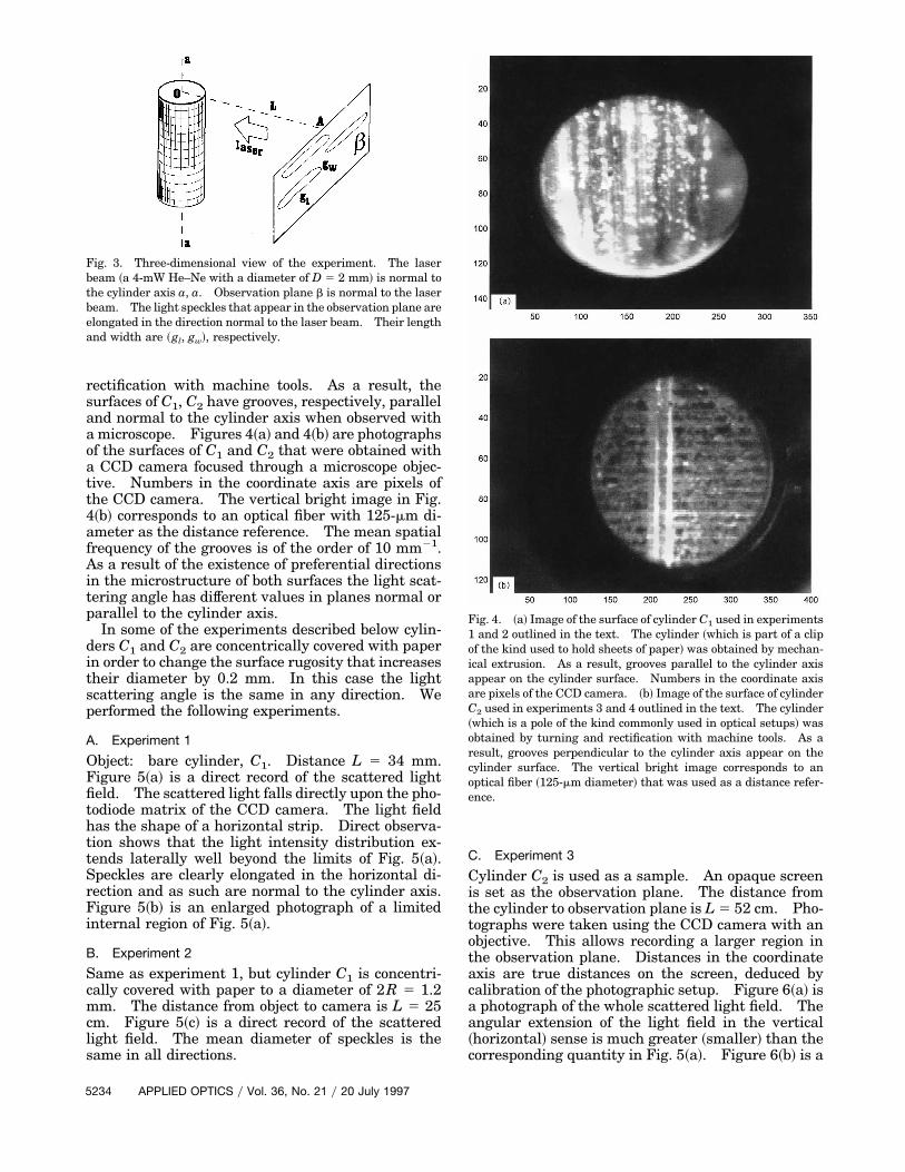
rectification with machine tools. As a result, thesurfaces of C1, C2 have grooves, respectively, paralleland normal to the cylinder axis when observed witha microscope. Figures 4~a! and 4~b! are photographsof the surfaces of C1 and C2 that were obtained witha CCD camera focused through a microscope objec-tive. Numbers in the coordinate axis are pixels ofthe CCD camera. The vertical bright image in Fig.4~b! corresponds to an optical fiber with 125-mm di-ameter as the distance reference. The mean spatialfrequency of the grooves is of the order of 10 mm21.As a result of the existence of preferential directionsin the microstructure of both surfaces the light scat-tering angle has different values in planes normal orparallel to the cylinder axis.
In some of the experiments described below cylin-ders C1 and C2 are concentrically covered with paperin order to change the surface rugosity that increasestheir diameter by 0.2 mm. In this case the lightscattering angle is the same in any direction. Weperformed the following experiments.
A. Experiment 1
Object: bare cylinder, C1. Distance L 5 34 mm.Figure 5~a! is a direct record of the scattered lightfield. The scattered light falls directly upon the pho-todiode matrix of the CCD camera. The light fieldhas the shape of a horizontal strip. Direct observa-tion shows that the light intensity distribution ex-tends laterally well beyond the limits of Fig. 5~a!.Speckles are clearly elongated in the horizontal di-rection and as such are normal to the cylinder axis.Figure 5~b! is an enlarged photograph of a limitedinternal region of Fig. 5~a!.
B. Experiment 2
Same as experiment 1, but cylinder C1 is concentri-cally covered with paper to a diameter of 2R 5 1.2mm. The distance from object to camera is L 5 25cm. Figure 5~c! is a direct record of the scatteredlight field. The mean diameter of speckles is thesame in all directions.
Fig. 3. Three-dimensional view of the experiment. The laserbeam ~a 4-mW He–Ne with a diameter of D 5 2 mm! is normal tothe cylinder axis a, a. Observation plane b is normal to the laserbeam. The light speckles that appear in the observation plane areelongated in the direction normal to the laser beam. Their lengthand width are ~gl, gw!, respectively.
5234 APPLIED OPTICS y Vol. 36, No. 21 y 20 July 1997
C. Experiment 3
Cylinder C2 is used as a sample. An opaque screenis set as the observation plane. The distance fromthe cylinder to observation plane is L 5 52 cm. Pho-tographs were taken using the CCD camera with anobjective. This allows recording a larger region inthe observation plane. Distances in the coordinateaxis are true distances on the screen, deduced bycalibration of the photographic setup. Figure 6~a! isa photograph of the whole scattered light field. Theangular extension of the light field in the vertical~horizontal! sense is much greater ~smaller! than thecorresponding quantity in Fig. 5~a!. Figure 6~b! is a
Fig. 4. ~a! Image of the surface of cylinder C1 used in experiments1 and 2 outlined in the text. The cylinder ~which is part of a clipof the kind used to hold sheets of paper! was obtained by mechan-ical extrusion. As a result, grooves parallel to the cylinder axisappear on the cylinder surface. Numbers in the coordinate axisare pixels of the CCD camera. ~b! Image of the surface of cylinderC2 used in experiments 3 and 4 outlined in the text. The cylinder~which is a pole of the kind commonly used in optical setups! wasobtained by turning and rectification with machine tools. As aresult, grooves perpendicular to the cylinder axis appear on thecylinder surface. The vertical bright image corresponds to anoptical fiber ~125-mm diameter! that was used as a distance refer-ence.
Fig. 5. ~a! Light field scattered from cylinder C1 in the setup of Fig.3. The scattered light field has the shape of a narrow strip elon-gated in the horizontal direction. The light speckles are also elon-gated in the horizontal direction. ~b! Enlarged detail of a region ofthe light field in ~a!. ~c! Light field scattered from cylinder C1
concentrically covered with paper, which increases the surfaceroughness and destroys the anisotropy observed in Fig. 4~a!. Notethe difference with respect to ~a! and ~b!. In this photograph thespeckle dimensions are the same in all directions.
Fig. 6. ~a! Global photograph of the light field scattered fromcylinder C2. ~b! Enlarged detail of a region of the light field in ~a!.As in Figs. 5~a! and 5~b!, the light speckles are elongated in thehorizontal direction. ~c! Photograph of the light field scatteredfrom cylinder C2 concentrically covered with paper. Note the dif-ference with respect to ~a!. As in Fig. 5~c! the speckle dimensionsare the same in all directions.
20 July 1997 y Vol. 36, No. 21 y APPLIED OPTICS 5235
detailed photograph of the scattered light field ob-served on the screen. The diaphragm aperture islarge enough so that the speckles do not change withdiffraction.
D. Experiment 4
The photograph in Fig. 6~c! was taken in the sameconditions as Fig. 6~b! except that cylinder C2 is con-centrically covered with paper to a diameter of 2R 514.5 mm. As in Fig. 5~c!, no preferential direction isnoted in the scattered light field.
5. Interpretation of Experiments
We now compare the experimental records with thetheoretical conclusions outlined in Section 3.
A. Experiment 1
Laser diameter D is greater than cylinder diameter2R. The speckle length and width in the directionsnormal and parallel to the cylinder axis are, respec-tively, gl 5 lLy2R sin~uly4! and gw 5 lLyD, where ulis the value of the scattering angle in the directionnormal to the cylinder axis. The scattering angle inthe axial direction uw is estimated from Fig. 5~a!.The distance from the object to the camera is L 5 34mm. The linear extension of the light intensity dis-tribution in the vertical sense at this distance is ap-proximately 1.7 mm. Therefore we have uw ' 5 31022 rad. An additional problem appears when wetry to determine the value of ul as light is horizontallyscattered because of surface rugosity and also be-cause of reflection in the curved surface ~Fig. 2!. Toseparate both effects we performed an additional ex-periment. The diameter of the incident light beamwas reduced to 0.2 mm using a calibrated slit, thusreducing the angular aperture between specularlyreflected light rays. In this case ul is the differencebetween the angular aperture of the actually scat-tered beam ~which can be experimentally deter-mined! and the corresponding aperture of the beamreflected from a perfectly smooth surface ~which canbe easily deduced by geometric considerations!. Weobtained a value similar to that for scattering in thevertical direction ~ul ' 5 3 1022 rad!.
With these numerical values, the model of Section3 can be used to predict gl 5 lLy2R sin~uly4! ' 1 mmand gw 5 lLyD ' 0.01 mm, which approximatelyagree with the mean speckle dimensions observed inFigs. 5~a! and 5~b!.
B. Experiment 2
The theoretical predictions are gl 5 lLy2R sin~uy4!and gw 5 lLyD. Now the scattering angles are thesame in the directions normal and parallel to theaxis. Because of the extreme roughness of the papersheet, the scattering angle is of the order of magni-tude u ' p. Therefore at the distance L 5 25 cmtheory predicts that gl ' gw ' 0.1 mm, which approx-imately coincides with the mean diameter of specklesin Fig. 5~c!.
5236 APPLIED OPTICS y Vol. 36, No. 21 y 20 July 1997
C. Experiment 3
Note the striking difference between the light inten-sity distributions shown in Figs. 5~a! and 6~a!. Al-though the light field in Fig. 5~a! is narrow in theaxial direction and wide in the horizontal direction,the reverse is true for the light field in Fig. 6~a!.This is due to the difference in the microscopic struc-ture of the surfaces of cylinders C1 and C2. As ex-plained above, C1 was built by extrusion in the axialdirection so that its surface has grooves in the axialdirection. Cylinder C2 was built by mechanicalturning so that it has quasi-periodic grooves in thedirection normal to the cylinder axis. This is thereason horizontal interference fringes appear in Fig.6~a!. With a procedure similar to the one used ininterpretation of experiment 1, we found ul ' 4 31022 rad. With these values we obtained gl ' 2 mmand gw ' 0.15 mm, which approximately coincidewith the mean dimensions of speckles in Fig. 6~b!.
D. Experiment 4
The theoretical values are g ' gw ' 0.15 mm, whichare somewhat smaller than the mean diameter ofspeckles observed in Fig. 6~c!.
6. Conclusions
The dimension of speckles in the light field scatteredfrom an object is an essential quantity in specklemetrology. This dimension determines the smallestobject displacement that can be measured usingspeckle photography. In the case of a flat object~null curvature! the speckle dimensions are the samein all the directions of the observation plane. Aninitial point that we have stressed is that for a curvedobject the dimensions of light speckles depend on theobject surface curvature. The speckle length in agiven direction s' depends on the surface curvature ina plane section containing the direction s' and thesurface normal n'. Therefore, the displacement of anobject with an arbitrarily curved surface cannot bemeasured with the same precision in different direc-tions. This remark is especially relevant for metro-logical methods developed recently by Yamaguchi etal.,4,19,20 which deal directly with cylindrical objectscommonly used in industrial applications. As an ex-ample we studied the particular case of a cylindricalsurface with two different curvature radii ~R, `! cor-responding to sections normal to and containing thecylinder axis, respectively. We have experimentallyshown that the dimensions of speckles in directionsnormal and parallel to the cylinder axis depend onboth the corresponding surface curvature and surfacerugosity. We note that not only the surface curva-ture but also the surface rugosity can differ in differ-ent directions and that both quantities have aninfluence on the resulting speckle dimensions. Thiswas demonstrated by using two cylinders as sampleswhose surfaces were grooved in perpendicular direc-tions, coinciding in turn with the cylinder axis andwith the direction normal to it. A theoretical modeltaking into account the observed dependence on cur-
vature and rugosity has been proposed. To simplifythe resulting calculations it was assumed that light ishomogeneously scattered from the object surfacewithin a limited angle. In spite of the obviously ap-proximate nature of this scattering model, theoreticalpredictions explain satisfactorily the main propertiesof the experimental records. First, the model pre-dicts that for increasing values of the scattering anglethe mean dimensions of light speckles tend to havethe same value in all the directions. In other words,speckles tend to be round for rough surfaces.Second, it predicts that, for decreasing values of thescattering angle ~smooth surface! in the direction nor-mal to the cylinder axis, the speckles are lengthenedin this direction. The same lengthening occurs fordecreasing values of the ratio ~RyD! between the cyl-inder and the incident laser beam radius. In thiscase the light speckles are no longer round but aredashlike. Although quantitative differences of theorder of magnitude 2 are found in some cases, themodel systematically yields correct predictions of thequalitative properties of the light field. Also thequantitative differences could be well explained byintroducing in the model a more realistic expressionfor the angular dependence of scattered light inten-sity.5,10
As a final comment, we stress the increased indus-trial importance of techniques of the kind describedin Refs. 19 and 20 for the analysis of strain andtorque on cylindrical objects. The analysis that wehave developed constitutes a contribution for deter-mination of the resolution limit of these techniques,which is fixed by the shape and dimensions of lightspeckles in the scattered light field.
References1. J. M. Burch and J. M. J. Tokarski, “Production of multiple
beam fringes from photographic scatterers,” Opt. Acta 15, 101–111 ~1968!.
2. M. Francon, “Information processing using speckle patterns,”in Laser Speckle and Related Phenomena, J. C. Dainty, ed. Vol.9 of Topics in Applied Physics ~Springer-Verlag, Berlin, 1975!,Chap. 5.
3. A. E. Ennos, “Speckle interferometry,” in Laser Speckle andRelated Phenomena, J. C. Dainty, ed., Vol. 9 of Topics in Ap-plied Physics ~Springer-Verlag, Berlin, 1975!, Chap. 6.
4. I. Yamaguchi, “Theory and applications of speckle displace-ment and decorrelation,” in Speckle Metrology, R. S. Sirohi, ed.~Marcel Dekker, New York, 1993!, pp. 1–39.
5. P. Beckmann and A. Spizzichino, The Scattering of Electro-magnetic Waves from Rough Surfaces ~Pergamon, Oxford,1963!.
6. L. J. Goldfisher, “Autocorrelation function and power spectraldensity of a laser-produced speckle pattern,” J. Opt. Soc. Am.55, 247–253 ~1965!.
7. H. Fujii and T. Asakura, “Effect of surface roughness on thestatistical distribution of image speckle intensity,” Opt. Com-mun. 11, 35–38 ~1974!.
8. J. W. Goodman, “Statistical properties of laser speckle pat-terns,” in Laser Speckle and Related Phenomena, J. C. Dainty,ed., Vol. 9 of Topics in Applied Physics ~Springer-Verlag, Ber-lin, 1975!, Chap. 2.
9. T. Asakura, “Surface roughness measurement,” in Speckle Me-trology, R. K. Erf, ed. ~Academic, New York, 1978!, Chap. 3.
10. J. M. Elson and J. M. Bennett, “Relation between the angulardependence of scattering and the statistical properties of op-tical surfaces,” J. Opt. Soc. Am. 69, 31–47 ~1979!.
11. E. Marx and V. Vorburger, “Direct and inverse problems forlight scattered by rough surfaces,” Appl. Opt. 29, 3613–3626~1990!.
12. L. Cao, T. Vorburger, A. Lieberman, and T. Lettieri, “Light-scattering measurement of the rms slopes of rough surfaces,”Appl. Opt. 30, 3221–3227 ~1991!.
13. E. Marx, B. Leridon, T. Lettieri, J. Song, and T. Vorburger,“Autocorrelation functions from optical scattering for one-dimensionally rough surfaces,” Appl. Opt. 32, 67–76 ~1993!.
14. T. Vorburger, E. Marx, and T. Lettieri, “Regimes of surfaceroughness measurable with light scattering,” Appl. Opt. 32,3401–3408 ~1993!.
15. M. A. Taubenblatt, “Light scattering from cylindrical struc-tures on surfaces,” Opt. Lett. 15, 255–257 ~1990!.
16. Y. Y. Fan and V. M. Huynh, “Light scattering from roughperiodic cylindrical surfaces,” Appl. Opt. 32, 3452–3458 ~1993!.
17. P. K. Rastogi, “Measurement of the derivatives of curved sur-faces using speckle interferometry,” J. Mod. Opt. 41, 659–661~1994!.
18. F. Kuik, J. F. de Haan, and J. W. Hovenier, “Single scatteringof light by circular cylinders,” Appl. Opt. 33, 4906–4918~1994!.
19. I. Yamaguchi and T. Fujita, “Laser speckle rotary encoder,”Appl. Opt. 28, 4401–4406 ~1989!.
20. M. Sjodahl and I. Yamaguchi, “Strain and torque measure-ments on cylindrical objects using the laser speckle straingauge,” Opt. Eng. 35, 1179–1186 ~1996!.
20 July 1997 y Vol. 36, No. 21 y APPLIED OPTICS 5237