Annals of DAAAM for 2012 & Proceedings of the 23rd International DAAAM Symposium, Volume 23, No.1, ISSN 2304-1382 ISBN 978-3-901509-91-9, CDROM version, Ed. B. Katalinic, Published by DAAAM International, Vienna, Austria, EU, 2012 Make Harmony between Technology and Nature, and Your Mind will Fly Free as a Bird Annals & Proceedings of DAAAM International 2012 WELDING OF THIN MOLYBDENUM SHEETS BY EBW AND GTAW KOLARIKOVA, M[arie]; KOLARIK, L[adislav] & VONDROUS, P[etr] Abstract: Two welding technologies (EBW, GTAW) were used to weld thin Mo sheets. Sheets thick 0.2 mm were welded by EBW and 0.4 mm thick samples were welded by GTAW welding methods. Welds were tested by means of metallography, optical microscopy, hardness measurement, chemical analysis etc. Mo welding is difficult because of inherently low ductility of Mo and high affinity to oxygen. Experiments proved that EBW is much better for welding thin Mo sheets, because it is done in vacuum and has much lower heat input. HAZ width of EBW was 1.4 mm compared to more than 35 mm for GTAW weld. Keywords: Molybdenum, EBW, GTAW, Welding, Micro- hardness 1. INTRODUCTION Molybdenum is a refractory metals that is used for special applications for high temperature use as aircragt parts, holders of tungsten filaments, anodes, heating elements of furnaces etc. One of interesting application is vessels for high temperature furnace remelting of glass and gemstones. For such an application thin Mo sheets are to be welded to create vessel of specific shape. To research welding of thin Mo sheet with the aim of creating vessel is purpose of this research. 2. EXPERIMENT Thin rolled pure Mo sheets of thickness 0.2 and 0.4 mm were welded by gas tungsten arc welding (GTAW) and electron beam welding (EBW). Experiments done include tensile strength testing with machine LabTest, chemical analysis was done by XRF spectrometr Olympus Delta, Vickers hardness HV0.5 was measured by IndentaMet 100 and metallographic observation done by optical microscope Carl Zeiss AxioObserver 1Dm. 3. BASE METAL Molybdenum (Mo) is refractory metal, with melting point 2620 °C. Compared to other refractory metals it has lower density, 10.2 g/cm 3 ) and low coefficient of thermal expansion, 4.8.10 -6 m/mK. Mo crystallizes in BCC lattice [1]. Molybdenum has low ductility and is produced by powder metallurgy. The product is influenced by purity of Mo powder and production process. It`s Brittle-ductile transition temperature is around room temperature. Typically rods, wires produced by powder metallurgy are widely available. But in our research thin Mo sheets produced by PM followed by rolling were used. Base material sheets were tested by tensile strength test and the results are in Tab. 1. Thickne ss [mm] Young modulus E [GPa] Yield strength Rp [MPa] Ultimate tensile strenght Rm [MPa] Ductility A80 [%] Hardness [HV0.5] 0,2 79 1214 1530 0.9 320 0,4 48 759 968 2.3 280 Tab. 1. Tensile strength test results for base material As visible, the Mo sheets have very low ductility, 1- 2 %, so no drawing or sheet metal working is possible (the vessel forming by deep drawing is not possible), so welding needs to be used. Even when flanging and bending was used as preparation of semiproduct before welding, cracks were created at the edges. The band structure of base metal is seen at metallographic macrographs at fig. 1, 2. Fig. 1. Macrograph of Mo base metal 0.2 mm structure Fig. 2. Macrograph of Mo base metal 0.4 mm structure - 1005 -
Transcript
Annals of DAAAM for 2012 & Proceedings of the 23rd International DAAAM Symposium, Volume 23, No.1, ISSN 2304-1382
ISBN 978-3-901509-91-9, CDROM version, Ed. B. Katalinic, Published by DAAAM International, Vienna, Austria, EU, 2012
Make Harmony between Technology and Nature, and Your Mind will Fly Free as a Bird
Abstract: Two welding technologies (EBW, GTAW) were used
to weld thin Mo sheets. Sheets thick 0.2 mm were welded by
EBW and 0.4 mm thick samples were welded by GTAW welding
methods. Welds were tested by means of metallography, optical
microscopy, hardness measurement, chemical analysis etc. Mo
welding is difficult because of inherently low ductility of Mo
and high affinity to oxygen. Experiments proved that EBW is
much better for welding thin Mo sheets, because it is done in
vacuum and has much lower heat input. HAZ width of EBW
was 1.4 mm compared to more than 35 mm for GTAW weld.
Keywords: Molybdenum, EBW, GTAW, Welding, Micro-
hardness
1. INTRODUCTION
Molybdenum is a refractory metals that is used for
special applications for high temperature use as aircragt
parts, holders of tungsten filaments, anodes, heating
elements of furnaces etc. One of interesting application is
vessels for high temperature furnace remelting of glass
and gemstones. For such an application thin Mo sheets
are to be welded to create vessel of specific shape. To
research welding of thin Mo sheet with the aim of
creating vessel is purpose of this research.
2. EXPERIMENT
Thin rolled pure Mo sheets of thickness 0.2 and 0.4
mm were welded by gas tungsten arc welding (GTAW)
and electron beam welding (EBW). Experiments done
include tensile strength testing with machine LabTest,
chemical analysis was done by XRF spectrometr
Olympus Delta, Vickers hardness HV0.5 was measured
by IndentaMet 100 and metallographic observation done
by optical microscope Carl Zeiss AxioObserver 1Dm.
3. BASE METAL
Molybdenum (Mo) is refractory metal, with melting
point 2620 °C. Compared to other refractory metals it has
lower density, 10.2 g/cm3) and low coefficient of thermal
expansion, 4.8.10-6
m/mK. Mo crystallizes in BCC lattice
[1]. Molybdenum has low ductility and is produced by
powder metallurgy. The product is influenced by purity
of Mo powder and production process. It`s Brittle-ductile
transition temperature is around room temperature.
Typically rods, wires produced by powder metallurgy
are widely available. But in our research thin Mo sheets
produced by PM followed by rolling were used. Base
material sheets were tested by tensile strength test and
the results are in Tab. 1.
Thickne
ss [mm]
Young modulus
E [GPa]
Yield strength Rp
[MPa]
Ultimate
tensile
strenght Rm [MPa]
Ductility
A80 [%]
Hardness
[HV0.5]
0,2 79 1214 1530 0.9 320
0,4 48 759 968 2.3 280
Tab. 1. Tensile strength test results for base material
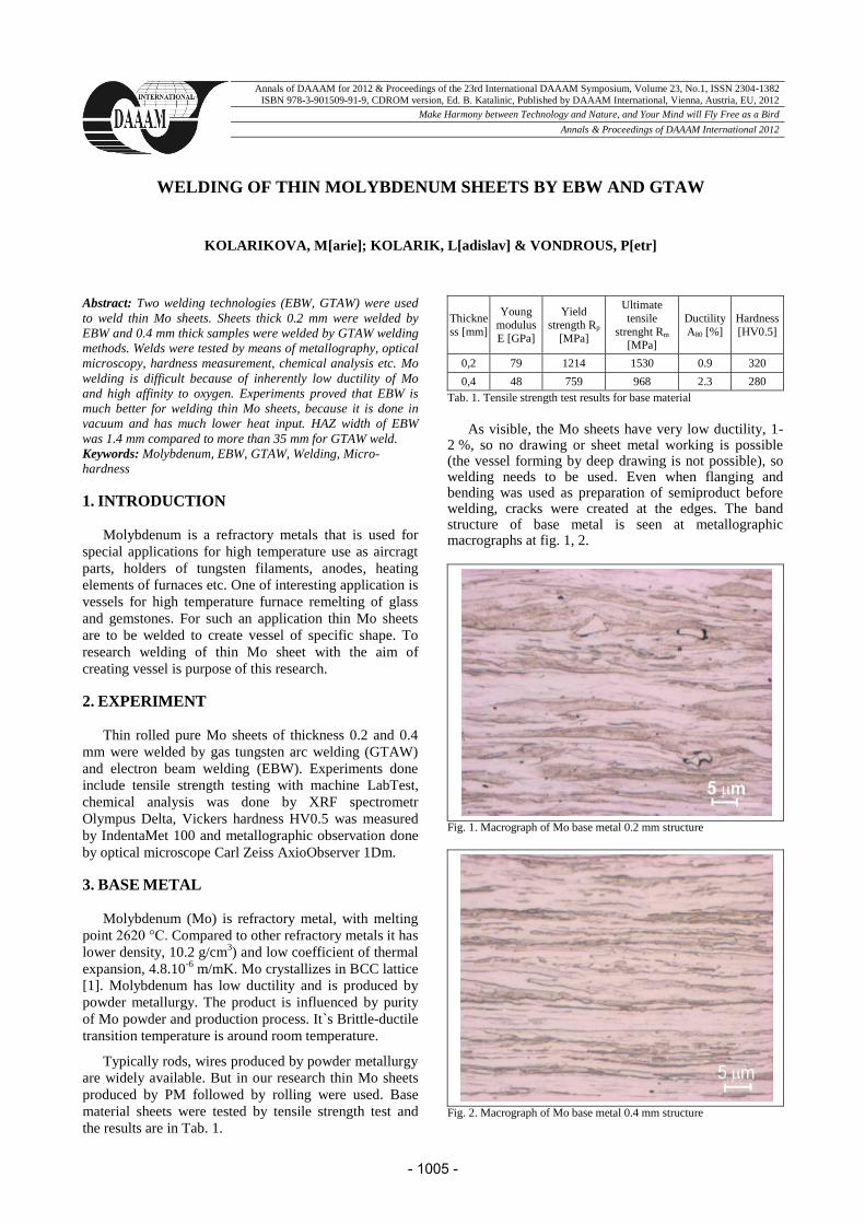
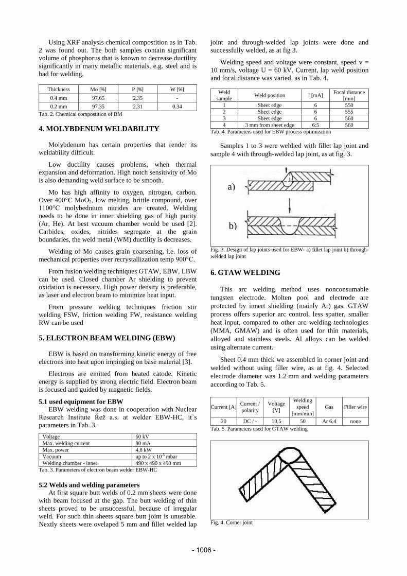
As visible, the Mo sheets have very low ductility, 1-
2 %, so no drawing or sheet metal working is possible (the vessel forming by deep drawing is not possible), so welding needs to be used. Even when flanging and bending was used as preparation of semiproduct before welding, cracks were created at the edges. The band structure of base metal is seen at metallographic macrographs at fig. 1, 2.
Fig. 1. Macrograph of Mo base metal 0.2 mm structure
Fig. 2. Macrograph of Mo base metal 0.4 mm structure
- 1005 -
Using XRF analysis chemical compostition as in Tab.
2 was found out. The both samples contain significant
volume of phosphorus that is known to decrease ductility
significantly in many metallic materials, e.g. steel and is
bad for welding.
Thickness Mo [%] P [%] W [%]
0.4 mm 97.65 2.35 -
0.2 mm 97.35 2.31 0.34
Tab. 2. Chemical compostition of BM
4. MOLYBDENUM WELDABILITY
Molybdenum has certain properties that render its
weldability difficult.
Low ductility causes problems, when thermal
expansion and deformation. High notch sensitivity of Mo
is also demanding weld surface to be smooth.
Mo has high affinity to oxygen, nitrogen, carbon.
Over 400°C MoO2, low melting, brittle compound, over
1100°C molybednium nitrides are created. Welding
needs to be done in inner shielding gas of high purity
(Ar, He). At best vacuum chamber would be used [2].
Carbides, oxides, nitrides segregate at the grain
boundaries, the weld metal (WM) ductility is decreases.
Welding of Mo causes grain coarsening, i.e. loss of
mechanical properties over recrystallization temp 900°C.
From fusion welding techniques GTAW, EBW, LBW
can be used. Closed chamber Ar shielding to prevent
oxidation is necessary. High power density is preferable,
as laser and electron beam to minimize heat input.
EBW is based on transforming kinetic energy of free
electrons into heat upon impinging on base material [3].
Electrons are emitted from heated catode. Kinetic
energy is supplied by strong electric field. Electron beam
is focused and guided by magnetic fields.
5.1 used equipment for EBW
EBW welding was done in cooperation with Nuclear
Research Institute Řež a.s. at welder EBW-HC, it`s
parameters in Tab..3.
Voltage 60 kV
Max. welding current 80 mA
Max. power 4,8 kW
Vacuum up to 2 x 10⁻⁵ mbar
Welding chamber - inner 490 x 490 x 490 mm
Tab. 3. Parameters of electron beam welder EBW-HC
5.2 Welds and welding parameters
At first square butt welds of 0.2 mm sheets were done
with beam focused at the gap. The butt welding of thin
sheets proved to be unsuccessful, because of irregular
weld. For such thin sheets square butt joint is unusable.
Nextly sheets were ovelaped 5 mm and fillet welded lap
joint and through-welded lap joints were done and
successfully welded, as at fig 3.
Welding speed and voltage were constant, speed v =
10 mm/s, voltage U = 60 kV. Current, lap weld position
and focal distance was varied, as in Tab. 4.
Weld
sample Weld position I [mA]
Focal distance
[mm]
1 Sheet edge 6 550
2 Sheet edge 6 555
3 Sheet edge 6 560
4 3 mm from sheet edge 6:5 560
Tab. 4. Parameters used for EBW process optimization
Samples 1 to 3 were weldied with fillet lap joint and
sample 4 with through-welded lap joint, as at fig. 3.
Fig. 3. Design of lap joints used for EBW- a) fillet lap joint b) through-
welded lap joint
6. GTAW WELDING
This arc welding method uses nonconsumable
tungsten electrode. Molten pool and electrode are
protected by innert shielding (mainly Ar) gas. GTAW
process offers superior arc control, less spatter, smaller
heat input, compared to other arc welding technologies
(MMA, GMAW) and is often used for thin materials,
alloyed and stainless steels. Al alloys can be welded
using alternate current.
Sheet 0.4 mm thick we assembled in corner joint and
welded without using filler wire, as at fig. 4. Selected
electrode diameter was 1.2 mm and welding parameters
according to Tab. 5.
Current [A] Current /
polarity
Voltage
[V]
Welding
speed
[mm/min]
Gas Filler wire
20 DC / - 10.5 50 Ar 6.4 none
Tab. 5. Parameters used for GTAW welding
Fig. 4. Corner joint
a)
b)
- 1006 -
7. RESULTS
EBM welded lap joints are without oxides as at fig. 5.
Measured weld and HAZ width is in Tab. 6. No cracks
were found in WM or HAZ, because of small width of
weld and HAZ together with welding in vacuum.
Sample EBW 1 2 3 4
Weld width [mm] 0.64 0.80 0.68 0.62
HAZ width [mm] 1.1 1.4 1.1 1.4
Tab. 6. Weld and heat affected zone (HAZ) width
Fig. 5. Sample welded by EBM
Metallographic macrographs of EBM welds are at fig.
6 – 8. Sample EBW 1, 2, 3 were welded with same current 6 mA and welding distance was increased from 550 mm, to 555, 560 mm. By this, weld width did increase and weld face reinforcement decreased with it. From the point of view of weld shape, the sample 3 is the most suitable
Fig. 6. Metallographic macrograph EBW 1
Fig. 7 Metallographic macrograph EBW 2
For sample EBW 4, weld-through lap weld, current
6.5 mA and focal distance were used. Weld pool sagged
and resulting weld has underfill, because of sheets gap.
Macrograph of GTAW weld is at fig. 9. Weld size
and HAZ are at Tab. 7. Because of limited size of welded
sheet (width 35 mm), heat input of the GTAW is so big
that all the sample was heat affected.
Fig. 8. Metallographic macrograph EBW 3
Sample GTAW
Weld bead width [mm] 1.70
HAZ width over 35 mm
Tab. 7. GTAW weld bead and HAZ width
Fig. 9. Metallographic macrograph of GTAW weld
Fig. 10. Weld metal microstructure of GTAW weld, mag. 200x
There were no inner defects found in the welds.
Micrographs are at fig. 1, 2 for base metal, at fig. 10 to
- 1007 -
13 are from welded samples. Obviously welding did cause recrystallization of BM molybdenum. Fig. 10 shows cast like grain structure, caused by big heat input of GTAW. Big irregular grains (40-140 µm) with dendrites are present in weld metal, in HAZ there are polyedric grains of size 10-40 µm with visible twins.
Fig. 11. Weld metal microstructure of EBM weld, mag. 200x
Microstucture of EBW samples is at fig. 11 and 13.
WM is composed by regular polyedric grains with size 20-40 µm. HAZ zone composes from grain of various size 5-30 µm.
Fig. 12. HAZ microstructure of GTAW weld, mag. 200x
Difference of EBW and GTAW microstructure is very different in grain size and shape. In WM area GTAW weld is crystallizing in columnar dendritic morphology. EBM weld crystallizes in cellula morphology, because of much higher temperature gradient, when cooling.
Fig. 13. HAZ microstructure of EBM weld, mag. 200x
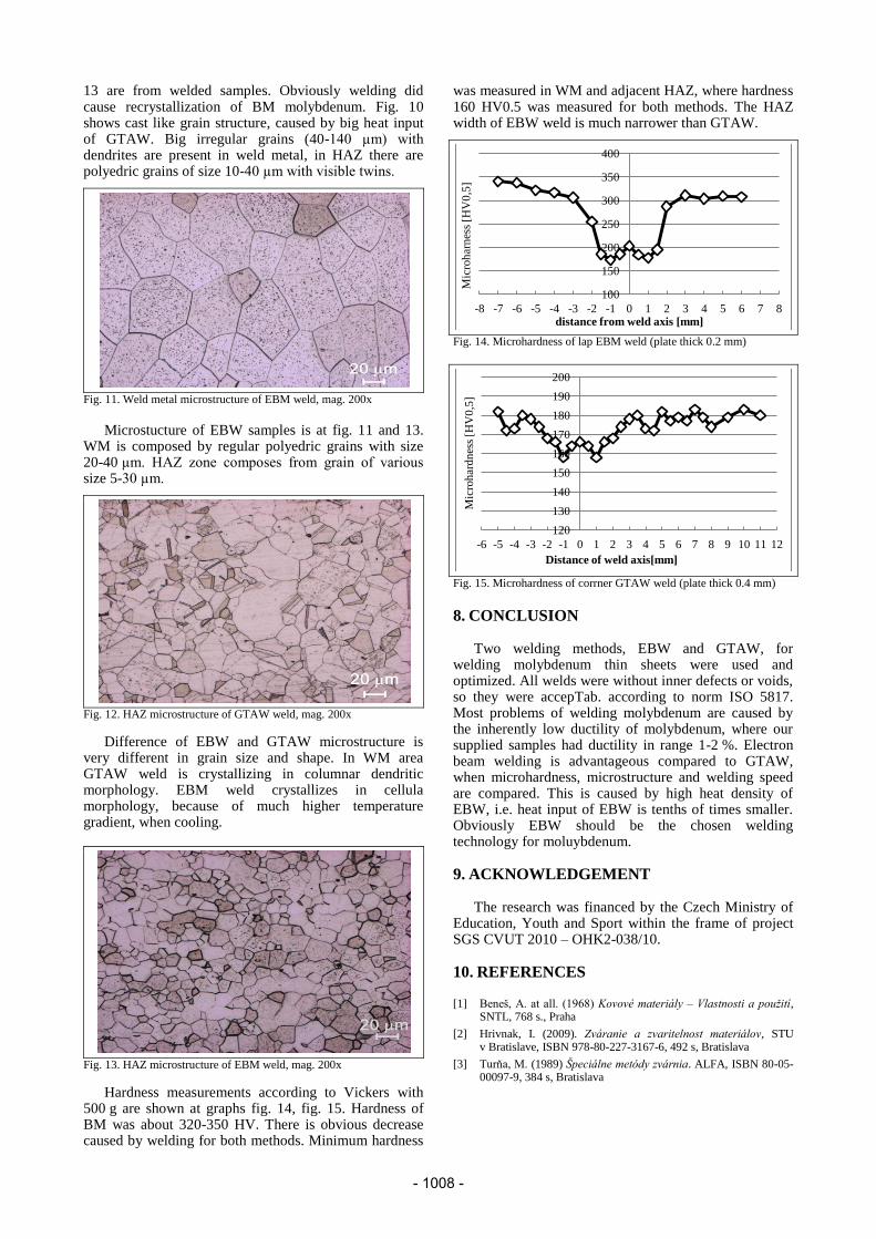
Hardness measurements according to Vickers with 500 g are shown at graphs fig. 14, fig. 15. Hardness of BM was about 320-350 HV. There is obvious decrease caused by welding for both methods. Minimum hardness
was measured in WM and adjacent HAZ, where hardness 160 HV0.5 was measured for both methods. The HAZ width of EBW weld is much narrower than GTAW.
Fig. 14. Microhardness of lap EBM weld (plate thick 0.2 mm)
8. CONCLUSION Two welding methods, EBW and GTAW, for
welding molybdenum thin sheets were used and optimized. All welds were without inner defects or voids, so they were accepTab. according to norm ISO 5817. Most problems of welding molybdenum are caused by the inherently low ductility of molybdenum, where our supplied samples had ductility in range 1-2 %. Electron beam welding is advantageous compared to GTAW, when microhardness, microstructure and welding speed are compared. This is caused by high heat density of EBW, i.e. heat input of EBW is tenths of times smaller. Obviously EBW should be the chosen welding technology for moluybdenum.
9. ACKNOWLEDGEMENT The research was financed by the Czech Ministry of
Education, Youth and Sport within the frame of project SGS CVUT 2010 – OHK2-038/10.
10. REFERENCES
[1] Beneš, A. at all. (1968) Kovové materiály – Vlastnosti a použití, SNTL, 768 s., Praha
[2] Hrivnak, I. (2009). Zváranie a zvaritelnost materiálov, STU v Bratislave, ISBN 978-80-227-3167-6, 492 s, Bratislava
[3] Turňa, M. (1989) Špeciálne metódy zvárnia. ALFA, ISBN 80-05-00097-9, 384 s, Bratislava