Page 1
1
ANNEXCURE 8 SPECIFICATIONS
GENERAL SPECIFICATION
This specification comprises of all aspects regarding the electrical installation for execution of
the VUT Electrical Master Plan Implementation. The Project Specification shall be read in
conjunction with the General Specifications in this document, installation and quality
specifications, schedule of quantities, drawings and Special Conditions of Contract included
in this document. Where contradictions occur between the documents, the most stringent
requirement shall rule, unless otherwise stated by the Engineer.
PRELIMINARIES
2.1.1 The contractor shall allow for the following specific requirements: Office accommodation for meetings held on site.
2.1.2 In addition to the specific requirements, detailed above, the contractor shall allow for his own preliminaries and/or overhead costs as required for the execution of the contract. It shall be divided into the following two sections:
Fixed-charge items such as: (SABS 1200A - 8.3)
• Contractual requirements.
• Establishment of facilities on site such as plant, sheds, water, Electricity,
lighting, etc.
• Removal of facilities from site after completion of work.
• Any other fixed-charge items.
Time related items:
• Contractual requirements.
• Operation & maintenance of facilities on site.
• Supervision.
• Company and head office overhead costs.
• Other time related items.
SPECIFICATION FOR 11KV XLPE CU CABLES
INTRODUCTION
The effect of a medium-voltage cable failure is generally severe in terms of customer outage
as well as repair cost. It is therefore important to ensure that MV cables comply with the
required specifications and are of acceptable quality.
Page 2
2
Scope
This specification covers the requirements for medium voltage cables in accordance with NRS
013 for 11kV and 22kV. The specific voltage required will be indicated in the project
specification and the schedule A and B attached.
3.2.1 NORMATIVE REFERENCES
The following documents contain provisions that, through reference in the text, constitute
requirements of this specification. All standards and specifications are subject to revision, and
parties to agreements based on this specification are encouraged to investigate the possibility
of applying the most recent editions of the documents listed below.
NRS 013: Medium-Voltage Cables
SANS 10198 (MULTIPLE PARTS): Installation of cables
3.2.2 DEFINITIONS AND ABBREVIATIONS
The definitions and abbreviations in NRS 013 shall apply to this specification.
3.2.3 REQUIREMENTS
General
The operating voltage of medium-voltage cables shall be;
a) 6,35/11 kV; b) 12,7/22 kV; or c) 600V/1000V
Cable types
(a) All cables and jointing and termination accessories used for power distribution
shall comply with the SANS 10198.
(b) Cables with copper conductors shall be used throughout unless otherwise
specified or approved.
(c) All unarmored cables shall be installed in metal trunking, sleeves or conduit
unless clearly specified to the contrary.
(d) XLPE Cables shall be used.
Competence of personnel
• It is a definite requirement that the Contractor shall only employ personnel fully
conversant with cable manufacturer's recommendations for joining and terminating
cables.
Page 3
3
Identification of cables
• Cables shall be identified at all terminations by means of punched metallic bands or
marked with labels or tags. (Refer also to SABS 0142).
• The use of PVC tape with punched characters is not acceptable.
• The identification numbers of cables shall be shown on "as built" drawings of the
Installation.
Trenching
General
• The Contractor shall be responsible for all trenching excavations unless specified to the
contrary.
• The Contractor shall, before trenching commences, familiarize himself with the routes
and site conditions and the procedure and order of doing the work shall be planned in
conjunction with the general construction programme for other services and building
requirements.
• The Contractor shall acquaint himself with the position of all the existing services such
as storm water pipes, water mains, sewer mains, gas pipes, telephone cables, etc.
before any excavations are commenced. For this purpose, he shall approach VUT's
representative, the local municipal authority and any other authority which may be
involved, in writing.
• The Contractor will be held responsible for damage to any existing services brought to
his attention by the relevant authorities and shall be responsible for the cost of repairs.
• The Contractor shall take all the necessary precautions and provide the necessary
warning signs and/or lights to ensure that the public and/or employees on site are not
endangered.
• The Contractor shall ensure that the excavations will not endanger existing structures,
roads, railways, other site constructions or other property.
Mechanical excavators
• Power driven mechanical excavators may be used for trenching operations provided
that they are not used in close proximity to other plant, services or other installations
likely to be damaged by the use of such machinery.
Page 4
4
• The use of power-driven mechanical excavators shall be subject to the approval of the
Engineer. Should the excavator produce trenches that exceed the required
dimensions, payment based on volumetric excavation rates will be calculated on the
required dimensions only.
Blasting
• No guarantee is given or implied that blasting will not be required.
• Should blasting be necessary and approved by the Engineer, the Contractor shall
obtain the necessary authority from the Engineer and Local Authorities.
• The Contractor shall take full responsibility and observe all conditions and regulations
set forth by the above authorities.
Routes
• Trenches shall connect the points shown on the drawings in a straight line. Any
deviations due to obstructions or existing services shall be approved by the Engineer
beforehand.
• The Engineer reserves the right to alter any cable route or portion thereof in advance
of cable laying. Payment in respect of any additional or wasted work involved shall be
at the documented rates.
• The removal of obstructions along the cable routes shall be subject to the approval of
the Engineer.
Shoring and Waterlogging
• The Contractor shall provide shoring for use in locations where there is a danger of the
sides of the trench collapsing due to waterlogging or other ground conditions. Refer to
the The Occupational Health and Safety Act.
• The strength of shoring must be adequate for site conditions prevailing and the shoring
must be braced across the trench.
• The Contractor shall provide all pumps and equipment required to remove accumulated
water from trenches. Water or any other liquid removed shall be disposed of without
any nuisance or hazard.
Page 5
5
3.9.1 Trenching
• Trenching shall be programmed in advance and the approved programme shall not be
departed from except with the consent of the Engineer.
• Trenches shall be as straight as possible and shall be excavated to the dimensions
indicated in this specification.
• The bottom of the trench shall be of smooth contour and shall have no sharp dips or
rises which may cause tensile forces in the cable during backfilling.
• The excavated material shall be placed adjacent to each trench in such a manner as to
prevent nuisance, interference or damage to adjacent drains, gateways, trenches,
water furrows, other works, properties or traffic. Where this is not possible the
excavated materials shall be removed from site and returned for backfilling on
completion of cable laying.
• Surplus material shall be removed from site and disposed of at the cost of the
Contractor.
• Trenches across roads, access ways or footpaths shall not be left open. If cables cannot
be laid immediately the Contractor shall install temporary "bridges" or cover plates of
sufficient strength to accommodate the traffic concerned.
• In the event of damage to other services or structures during trenching operations the
Contractor shall immediately notify the Engineer and institute repairs.
• Prior to cable laying the trench shall be inspected thoroughly and all objects likely to
cause damage to the cables either during or after laying shall be removed.
• Where ground conditions are likely to reduce maximum current carrying capacities of
cables or where the cables are likely to be subjected to chemical or other damage or
electrolytic action, the Engineer shall be notified before installing the cables. The
Engineer will advise on the course of action to be taken.
• Extreme care shall be taken not to disturb surveyor's pegs. These pegs shall not be
covered with excavated material. If the surveyor's pegs are disturbed, they shall be
replaced by a person qualified to do so.
Dimensions of trenches
• Cable trenches for one or two cables shall not be less than 300 mm wide and need not
be more than 450 mm wide. This dimension shall be valid for the total trench depth.
• The width shall be increased where more cables are installed to allow for the spacings
stipulated in par. 4.2.
Page 6
6
• Where trenches change direction or where cable slack is to be accommodated, the
Contractor shall ensure that the requirements of the relevant SABS Specification
regarding the bending radii of cables are met when determining trench widths.
• Trench depths shall be determined in accordance with cable laying depths and bedding
thickness.
• Payment will be made on a volumetric excavation rate calculated on the basis of the
given maximum dimensions or the actual dimensions, whichever is the lesser.
3.10.1 Joint holes
• Where cable joints are required to be made in the course of a cable run, a joint hole
shall be excavated of sufficient size to enable the cable jointer to work efficiently and
unimpeded.
3.10.2 Bedding
• The bottom of the trench shall be filled across the full width with a 75mm layer of
suitable soil sifted through a 6mm mesh and levelled off.
• Only sandy clay or loam soil with a satisfactory thermal resistivity (not exceeding 1,5°C
m/W) may be used for this purpose. Sea or river sand, ash, chalk, peat, clinker or
clayey soil shall not be used. The use of crusher sand is acceptable.
• Where no suitable soil is available on site, the Contractor shall import fill from elsewhere
and make all the necessary arrangements to do so. The cost of importing soil for
bedding purposes shall be included in the unit rates for excavations.
• After cable laying a further layer of bedding shall be provided to extend to 75 mm above
the cables.
• The bedding under joints shall be fully consolidated to prevent subsequent settling.
3.10.3 Cable Sleeves
• Where cables cross under roads, railway tracks, other service areas, etc. and where
cables enter buildings, the cables shall be installed in Polyethylene (6mm thickness),
asbestos cement pipes or earthenware pipes. Pitch fibre and PVC pipes are not
acceptable because of the adhesion that occurs after a period of time between the
pipe and the sheathing or outer serving of the cables.
• Pipes shall be joined in accordance with the manufacturer's instructions.
• Sleeves shall cross roads and railway tracks at right angles.
Page 7
7
• Sleeves shall have a minimum diameter of 100mm. They shall extend at least 2m
beyond the tracks of a railway line or of the outermost tracks where there is more than
one line. In the case of roads, the sleeves shall extend at least 1m beyond the road
edge or kerb on both sides of the road.
• All sleeves shall be graded 1:400 for water drainage.
• Cable sleeves shall be installed to the spacings and depths stated in paragraph 4
below.
• Galvanised metallic sleeves up to and including 76mm dia. shall be supplied and
installed by the contractor.
• The ends of all sleeves shall be sealed with a non-hardening watertight compound after
the installation of cables. All sleeves intended for future use shall likewise be sealed.
3.10.4 Backfilling
• The Contractor shall not commence with the backfilling of trenches without prior
notification to the Engineer so that the cable installation may be inspected. Should the
Contractor fail to give a timeous notification, the trenches shall be re-opened at the
Contractor's cost. Such an inspection will not be unreasonably delayed.
• For medium voltage cables (1 kV to 11 kV) a coloured plastic marking tape shall be
installed 400 mm above the cable. The tape shall be yellow, marked with the words
"ELECTRIC CABLE/ELEKTRIESE KABEL" in red. These markings shall not be more
than 1m apart from centre to centre.
• Backfilling shall be undertaken with soil suitable to ensure settling without voids. The
maximum allowable diameter of stones present in the backfill material, is 75mm.
• The Contractor shall have allowed in his tender for the importation of suitable backfill
material if required.
• The backfill shall be compacted in layers of 150mm and sufficient allowance shall be
made for final settlement. The Contractor shall maintain the refilled trench at his
expense for the duration of the contract. Surplus material shall be removed from site
and suitably disposed of.
• On completion, the surface shall be made good to match the surrounding area.
• In the case of roadways or paved areas the excavations shall be consolidated to the
original density of the surrounding material and the surface finish reinstated.
• Cable Markers (for HV cables only, except where otherwise specified)
• Cable markers shall be provided along all HV cable routes but need only be provided
along LV cable routes where specified.
Page 8
8
• Cable markers shall consist of concrete blocks in the shape of truncated pyramids,
approx. 300mm high, 150 x 150mm at the top and 250 x 250mm at the bottom.
• Brass plates shall be cast into the tops of the blocks in such a manner that they cannot
be prised loose. The wording "ELECTRIC CABLE/ELEKTRIESE KABEL" shall be
stamped on the brass plates as well as direction arrows and the cable voltage rating.
• Cable markers shall be installed on the surface along all the underground routes and
shall project 35 mm above normal ground level unless the projected markers could be
a hazard to pedestrian or other traffic in which case, they shall be installed flush with
the surface.
• Cable markers shall be installed at the beginning and end of a cable run (e.g., where a
cable enters a substation or building), at all changes of direction, above all joints, above
cable pipe entries and exits and at intervals not exceeding 50 m along the cable route
• The position of cable markers shall be indicated on the "as built" drawings.
3.10.5 Transnet, provincial administration or national road crossings
• The Contractor shall not trench beneath any railway tracks without the TRANSNET
Administration's supervision. The Contractor shall request the Engineer timeously to
arrange for the necessary supervision. The cost of such supervision will be paid for by
VUT.
• The Engineer will arrange for the necessary wayleave and permission to cross
TRANSNET property and railway tracks, or Provincial or National road reserves and
TELKOM Authority approval of proposed cable routes.
• The Contractor shall carry out the crossing installation in strict accordance with the
TRANSNET and Provincial Administration's requirements and stipulations. Where
these requirements are in contradiction with this specification, the Engineer's ruling
shall be sought.
• The Contractor shall ensure that he will comply with the various Administration's
requirements regarding crossing of Provincial and National roads, especially with
regard to the safeguarding of the public. The Contractor shall also provide proof of
adequate insurance cover against any claim from any accident as a result of work done
by the Contractor during the crossing operation. The VUT shall also be indemnified
from all liability in this regard.
• The Contractor shall liaise with the various Administrations well in advance regarding
the intended dates, times and expected duration of the crossing operations and obtain
Page 9
9
their approval of the programme and method of operation before commencing with the
work.
INSTALLATION OF UNDERGROUND CABLES
4.1.1 Installation Depths
• Cables shall be installed at the following minimum depths below final ground level: Up
to 11kV: 8OOmm
• All cable depth measurements shall be made to the top of the cable when laid directly
in ground or to the top of the duct or sleeve where these are provided.
• The above depths shall apply to the top layer where cables are installed in layers.
• The Contractor may only deviate from the above depths provided prior authority in
writing has been obtained from the Engineer. In this event the cables shall be protected
with a suitable concrete covering.
• The depth of cable pipes or ducts beneath railway lines or roads shall be not less than
1,1 m below the formation level.
Cable spacings
• Cables installed in the same trench shall be laid parallel to each other with the following
spacings between cables (LV: up to 1 kV; HV: 1 kV to 11 kV):
LV/LV : 2 cable diameters
LV/HV : 150mm minimum
HV/HV : 150mm minimum
LV/HV/PILOT : 1 cable diameter
• Where HV and LV cables have to be installed in the same trench, both shall be laid at
a depth of 800 mm and then covered with 200mm of soil. The soil shall then be
compacted, and then backfilled layer by layer and compacted until the trench is
completely backfilled.
• Cables for telephones, communication systems and other low voltage systems (less
than 50 V) shall be separated from power cables by at least 1m. All control or pilot
cables without a lead sheath and steel armouring shall be laid at least 300mm from
power cables.
Page 10
10
• Cables shall not be buried on top of each other unless layers are specified. The
minimum spacing between layers shall be 200mm.
Cable laying
• Except where ducts, tunnels or pipes are provided, cables shall be laid directly in the
ground.
• The cable shall be removed from the drum in such a manner that the cable is not
subjected to twisting or tension exceeding that stipulated by the cable manufacturer.
• Cable rollers shall be used as far as possible to run out cables. Rollers shall be spaced
so that the length of cable in the trench will be totally suspended during the laying
operation and sufficiently close to prevent undue sagging and the cable from touching
the ground. Rollers shall also be placed in the trench in such a manner that they will
not readily capsize.
• Cable rollers shall have no sharp projecting parts liable to damage the cables.
• Where cables have to be drawn around corners, well-lubricated skid plates shall be
used. The skid plates shall be securely fixed between rollers and shall constantly be
examined during cable laying operations.
• Where cables have to be drawn through pipes or ducts, a suitable cable sock shall be
used and particular care shall be exercised to avoid abrasion, elongation or distortion
of any kind. In the case of oil filled cables, a cable sock may never be used. Special
eyes giving access to the interior of the cable, must be utilised.
• The maximum allowable tension when pulling a cable, is 70 N/mm2 of conductor area.
• It will be assumed that the price or rates contained in the tender includes for the
installation of cables in pipes and ducts or below existing or newly installed services.
• The Engineer shall be informed timeously of the intention to carry out all cable laying
operations to allow an inspection of the works if so required.
Installation of cables in concrete trenches
General
• This paragraph covers the installation of cables in building trenches, service ducts, etc.
The trenches, ducts, etc. inside buildings will be constructed and installed by others.
4.4.1 Installation
• Cables shall be installed in one of the following ways:
(a) On horizontal cable trays.
Page 11
11
(b) On horizontal metal supports with suitable clamps.
(c) On vertical cable trays or metal. supports fixed to the side of the trench. The
cables shall be clamped in position.
• Cables shall not be bunched and laid on the floor of the building trenches.
Covers
• The covering of concrete trenches shall as a rule fall outside the scope of the electrical
installation. The Contractor shall however be responsible for the cutting or drilling and
smoothing of holes for cables through chequer plates, concrete or other coverings as
required.
• Cables shall enter and exit the trench through sleeves protruding 300mm beyond the
covering. The sleeves shall be permanently secured in position and the open space
between the cable and sleeves shall be sealed with a non-hardening, watertight
compound.
Filled trenches
• Where specified, floor trenches shall be filled with fine crusher sand (no river or see
sand).
• If a sand filling is specified, the cables shall be fixed to non-corroding supports.
• Sand-filled trenches other than in substations shall be covered in one of the following
ways:
(a) Reinforced concrete covers.
(b) Sand and cement screed.
(c) Removable chequer plates.
• Method (a) above shall be used where vehicular traffic may be encountered over
trenches. Unless otherwise specified allowance for a mass of 2 tons shall be made.
• Cable trenches in substations, switch rooms and generator rooms shall be covered in
accordance with the Engineer's standard specification.
Fixing of cables to trays or structures
Installation
• Cables may be installed in one of the following ways:
(a) On horizontal cable trays.
(b) Against vertical cable trays with suitable clamps.
Page 12
12
(c) Against horizontal or vertical metal supports or brackets with suitable clamps.
(d) On clamps which are fixed to the structure.
4.7.1 Clamps
• Suitable clamps (cleats) which will secure cables without damage shall be used. Metal
clamps or drilled hard wood blocks shall be used. Clamps shall consist of adjustable
metal wings which clamp to a metal support or consist of two halves that are bolted
together. The correct clamp size to fit the cable shall be used. Cables of different sizes
nay only be fixed by a common clamp when the clamp is specially made to
accommodate the various cables.
4.7.2 Spacing of Supports
• Two methods of supporting cables are found in practice. The most generally known
method is the restrained installation where the distance between supports is small
enough to prevent any noticeable sag in the cable. The alternative method is the
unrestrained installation where the distance between supports should be great enough
to ensure that there will be obvious sag in each span between supports.
• Large single core cables shall always be installed according to this method. Generally,
single core cables with conductors exceeding a cross sectional area of 185mm² should
be supported at spacings in excess of 2m since the sag between supports will safely
accommodate any thermal expansion.
• Reducing the spacing between the supports to 1,5m or less shall be avoided at all
costs, as expansion cannot be taken up by a change of sag and chances of sheath
failure become considerable.
Spacing of supports of restrained cables
• Additional cleats shall be installed at each bend or offset in the cable run. The maximum
distance between supports or cleats for multi-core control cables shall be 20 times the
outside diameter of the cable with a maximum spacing of 550mm for unarmoured
cables and 30 times the outside diameter of the cable with a maximum spacing of
900mm for armoured cables. Spacing of supports for cables for medium voltage
lighting shall be in accordance with Table 8 of SABS 0142. A minimum of 20mm
Page 13
13
ventilation clearance shall be maintained between cables and the wall to which they
are cleated.
Grouping and spacing of cables in buildings and structures
Spacing correction factors
• Cables shall as a rule be spaced two cable diameters apart, for which no grouping
correction factor need be applied.
Cables on different levels
• Where parallel cable runs are installed at different levels (e.g., on parallel cable trays)
and where the spacing of the layers is not specified, a minimum spacing of 300mm
shall be maintained.
Single core cables
• Where single core cables are installed along a three-phase circuit, the cables shall be
installed in trefoil formation and bound together at 300mm intervals.
Medium voltage cables
• Medium voltage cables shall be separated from other cables and services throughout
the installation and shall as far as possible be installed in separate floor trenches, pipes
or metal channels. Where this is not feasible a minimum spacing of 500 mm shall be
maintained.
Cables for other services
• Cables for telephones, communication systems and other low voltage systems (less
than 50 V) shall be separated from power cables. In building ducts, a physical barrier
shall be provided between power cables and cables for other services. Where
armoured cables are used for such other services, they shall be installed on separate
cable trays or shall otherwise be at least 1m away from power cables. Where
unarmoured cables are used for these other services, they shall be installed in
separate conduits or metal channels.
Table 1: Maximum spacing of support for restrained cables
Page 14
14
Cross-Sectional Area
of Cable
Conductors
(mm²)
MAXIMUM SPACING OF SUPPORTS (CLEATS) (mm) FOR
RESTRAINED CABLES
Wire Armored Cables
Other than Wire
Armored Cables and
Unarmored Cables
Horizontal
Cable Routes
Vertical Cable
Routes
Horizontal
Cable Routes
Vertical Cable
Routes
1,5
2,5
4,0
6,0
10,0
16,0
25,0
35,0
Bigger than 35,0
450
450
600
600
750
750
900
900
900
750
750
750
750
900
1000
1000
1000
1000
300
300
300
300
400
400
450
450
450
400
400
400
400
450
550
550
550
550
For larger cables the spacing shall be 10 x outside diameter of the cable.
TERMINATION AND JOINTING OF CABLES
General
• Cable ends shall be terminated with glands or in cable boxes with the associated
accessories such as clamps, shrouds, etc. complying in all respects with the
Engineer's quality specifications.
• Connection of cables to switchgear shall always be effected in such a way that the
various phases, seen from the front of the switchgear will be in the following positions:
No. 1 conductor: left (red) (A)
No. 2 conductor: center (white) (B)
No. 3 conductor: right (blue) (C)
• Exposed armouring shall be covered with bitumen-base paint.
• All cable ends shall be supplied with the necessary earth connection.
Page 15
15
• A channel or other approved means of support shall be provided to remove mechanical
stress from the glands.
• Cable cores shall be marked with heat-shrunk sleeves where necessary to identify the
phases. Refer to SABS 0142.
• The current-carrying capacity and breakdown voltage of the cable end shall be the
same as for the complete cable.
• Cables shall be terminated in accordance with the recommendations laid down by the
manufacturers of the cables and glands employed.
Termination of Paper-Insulated Cables
• The ends shall be terminated in cable end boxes filled with bituminous, cold filling or
resin oil semi-fluid compound or heat-shrinkable terminations in accordance with the
Engineer's standard specification.
• Heat-shrinkable materials shall only be used in exceptional circumstances with the
written permission of the Engineer.
• Before terminating or jointing paper-insulated cables, a test to establish the presence
of moisture must be carried out.
The following procedure may be followed:
(a) Place an adequate quantity of cable impregnating oil in a suitable container and
heat up to 130 C ± 5 C.
(b) Cut a small length (± 300mm) of the cable concerned and remove the armouring
and sheath, taking care not to handle the dielectric in any way.
(c) Dip a section of the outer insulating impregnated paper (belt paper) in the heated
oil, taking care not to contaminate the tapes with moisture from the hands. If
frothing appears on the surface of the oil, this is a clear indication of the presence
of moisture in the paper.
(d) The same procedure should then be repeated on the insulating impregnated
paper around the conductors (especially those layers closest to the conductors).
Frothing will also indicate the presence of moisture.
(e) Should only a small number of bubbles appear on the surface of the oil, this is an
indication of air bubbles on the paper and not moisture since the presence of
moisture will result in a series of bubbles rising to the surface of the oil for a
number of seconds, until all moisture has been removed.
Page 16
16
• The armouring shall be bonded to the main earth bar of the switchgear or transformer,
but the bond shall be easily removable for testing purposes.
• The lead sheath shall be wiped against the conical wiping gland.
• All cut cable ends which will be exposed to the atmosphere for more than two hours
shall be sealed and wiped to prevent penetration of moisture.
Termination of XLPE cables
• These cables shall only be used in exceptional circumstances and only with the written
permission of the Engineer.
• Cross-linked polyethylene cables (XLPE) shall be terminated in accordance with the
Engineer's standard specification.
• The copper tapes of the earth screen on the cable shall be bonded to the main earth
bar of the switchgear or transformer, but the bond shall be easily removable for testing
purposes.
• The cable shall be firmly secured on the switchgear by means of a clamp to prevent
mechanical stress on the cable and terminations.
Termination of PVC-insulated cables
• Cable ends shall be terminated by means of adjustable glands in accordance with the
Engineer's standard specification.
• The glands shall be fitted in accordance with the cable and gland manufacturer’s
instructions.
• The correct size and type of gland shall be used for the particular cable and application.
Connection of cable conductors
• Suitable lugs shall be used, preferably solidly sweated to the cable conductor ends.
Lugs may be crimped, using mechanical or pneumatic tools designed for this purpose,
on condition that evidence is submitted that the method used complies with the
performance requirements of BS 4579, Part 1: "COMPRESSION JOINTS IN
COPPER".
• Contact surfaces shall be thoroughly cleaned and smoothed and fixing bolts shall match
the hole size of the lug.
Page 17
17
• Cables that are connected to clamp type terminals where the clamping screws are not
in direct contact with the conductor, need not be lugged but the correct terminal size
shall be used.
• Ferrules shall be used as far as possible where cable conductors are connected directly
to equipment with screws against the conductor strands.
• When cutting away insulation from cable conductors to fit into lugs, care shall be taken
that no strands are left exposed. Under no circumstances may any of the conductor
strands be cut away to fit into lugs.
Joints
• Joints in cable runs will not be allowed unless specified in the Detail Technical
Specification or authorised by the Engineer.
• Jointing shall be carried out strictly in accordance with the manufacturer's instructions
and by personnel competent in jointing the types of cables used.
• During outdoor jointing operations, the joint bays shall be adequately covered by tents
of waterproof material suitably supported. Where necessary a trench shall be
excavated around the bay to prevent the ingress of moisture. The sides of the hole
shall be draped with small tarpaulin or plastic sheeting to prevent loose earth from
falling in during jointing operations.
• The joint shall not impair the anti-electrolysis characteristics of the cable.
• The Contractor shall notify the Engineer timeously of the day on which jointing is to be
carried out in order than an inspection may be arranged if so required. Any cable joint
not inspected by the Engineer because of insufficient notice being given, shall be
opened for inspection and redone at the discretion of the Engineer at the cost of the
contractor.
• HV cable joints on paper insulated cables shall be of the compound cast type and the
compound used shall comply with the Engineer's standard.
• HV cable joints on XLPE-insulated cables shall be of the heat shrinkable type and shall
comply with the Engineer's standard specification.
• LV cable joints shall be of the epoxy-resin type.
• Joints shall be fully water and air tight and shall be free of voids and air pockets.
• The crossing of cores in joints will not be permitted under any circumstances.
Page 18
18
Testing
• Each cable shall be tested after installation in accordance SABS 150 (up to 1 kV) and
SABS 97 (up to 11 kV) as well as the requirements of the Local and Supply Authorities.
• LV Cables shall be tested by means of a suitable megger at 1 kV and the insulation
resistance shall be tabulated and certified.
Table 2: Cable test voltage requirements
Cable Rating
(kV)
TEST VOLTAGE
(Applied for 15 minutes)
(kV)
Paper-insulated cables XLPE-
insulated
cables
6,6
11
Between conductors Conductors to sheath Conductors to
screen
AC
(r.m.s)
DC
AC
(r.m.s)
DC DC
12
20
18
30
12
20
18
30
11
18
* Medium Voltage test with DC to 2kV for 1 minute only. Discharge cable slowly via
discharge stick (1 minute). Clamp all conductors to earth for 24 hours.
• HV Cables shall be medium voltage tested and the exact leakage current shall be
tabulated and certified.
Page 19
19
• The Contractor shall make all arrangements, pay all fees and provide all equipment for
these tests. The cost of testing shall have been included in the tender price.
• The Contractor shall notify the Engineer timeously so that a representative of the VUT
may witness the tests.
• On completion of the tests on any cable, the Contractor shall without delay, submit
three copies of the certified Test Reports to the Engineer.
Measurements
• All measurements for payments shall be made jointly by the representatives of the VUT
and the Contractor and the Contractor shall obtain the signature of the Engineer’s
approval of such measurements.
• No allowance shall be made for the breaking away of the trench sides, other earth
movements or for trenches excavated in excess of the stipulated dimensions.
The classification shall be as follows:
Very hard rock shall mean rock that can only be excavated by means of explosives.
Hard rock shall mean granite, quartzitic sandstone, slate and rock of similar or greater
hardness, solid shale and boulders in general requiring the use of jack hammers and
other mechanical means of excavations.
Soft rock and earth shall mean rock and earth that can be loosened and removed by
hand-pick and shovel.
• Where very hard rock and hard rock are encountered, the prior approval of the Engineer
shall be obtained before proceeding with the excavation. This requirement is stipulated
in order to afford the Engineer the opportunity to determine whether an alternative
cable route is justified.
• All cable lengths indicated in the Detail Technical Specification and/or shown in the
cable route drawings shall be regarded as estimates and are given for tendering
purposes only. The successful tenderer shall measure actual cable lengths on site
before ordering.
• The final price for the supply and installation of all cables will be adjusted, on the basis
of the actual lengths of installed cables, in accordance with the unit rates quoted at the
time of tendering. Cable lengths shall be measured on site to the nearest 500mm for
this purpose and surplus cable will not be paid for.
Page 20
20
Completion
• The Engineer reserves the right to inspect the installation at any stage during the course
of construction. Such inspections will however not deem the portions inspected as
being complete or accepted and the Contractor shall remain responsible for completing
the installation fully in accordance with the Contract Documents.
• The Contractor shall carry out a final "as built" survey of the cable routes and present
to the Engineer "as built" route plans of the complete installation. The following
information shall be reflected on the plans or submitted as separate schedules with the
plans:
(a) Overall length of each cable.
(b) Locations of all joints (if any) in relation to permanent reference points.
Dimensions shall be shown and the method of triangulation i.e., two
dimensions to each joint, shall be used.
(c) Identification of each cable.
• The works will be deemed to be incomplete until all tests have been conducted
successfully and all "as built" drawings and schedules have been handed to the
Engineer.
Conductors
The standard conductor shall be stranded annealed copper with the cross-sectional areas
specified below:
Table 3: Standard conductor requirements
Construction
Rated voltage (kV)
11 22
Area (mm²)
3-core + 70mm2 BCEW
70
95
185
Page 21
21
XLPE cables
Shall comply with the requirements of NRS 013 with the following requirements detailed
below.
Construction
Three-core cable shall be type A (armored with steel wire armor).
Core identification
The cores of three-core cables shall be identified by the numbers 1, 2, 3, printed as numerals
or words either directly on the extruded semi-conducting core screen or on the semi-
conducting bedding tapes of each core, or by other acceptable means.
4.26.1 Outer sheath
The outer sheath shall be black PE type PS2.
Tests
Shall comply with the requirements of NRS 013.
Marking, labelling and packaging
Shall comply with the requirements of NRS 013.
Documentation
Documentation complying with the requirements of NRS 013 shall be submitted in a catalogue
format.
SPECIFICATION FOR 11KV XLPE CABLES
Table 4: Technical schedules A and B for 185mm2 Cu XLPE Cable
ITEM
DESCRIPTION
SCHEDULE A SCHEDULE B
Minimum
Requirements
Equipment Details (To
Be Completed By
Tenderer)
1 185mm² 11kV XLPE 3-core Cu SWA (Type A)
Page 22
22
ITEM
DESCRIPTION
SCHEDULE A SCHEDULE B
Minimum
Requirements
Equipment Details (To
Be Completed By
Tenderer)
1.1 Manufacturer’s name Tender to
specify
1.2 Country of Origin Tender to
specify
1.3 System operating voltage kV 11
1.4 Number of cores 3
1.5 Conductor size mm² 185
1.6 Cable type XLPE
1.7 Symmetrical fault level kA 25
1.8 Earth fault level kA 8
1.9 Marking requirements Required
1.10 Technical Catalogue to be provided with tender
documentation Required
1.11 Certified copy of type test to be provided with
tender documentation SABS 1339 Required
1.12 Drum length m 1500
Page 23
23
Table 5: Deviation schedule for 185mm2 Cu XLPE Cable
Any deviations offered to this specification shall be listed below with reasons for deviation. In
addition, evidence shall be provided that the proposed deviation will at least be more cost-
effective than that specified.
ITEM PROPOSED DEVIATION
Page 24
24
Table 6: Technical schedules A and B for 95mm2 Cu XLPE Cable
ITEM
DESCRIPTION
SCHEDULE A SCHEDULE B
Minimum
Requirements
Equipment Details (To
Be Completed By
Tenderer)
1 95mm² 11kV XLPE 3-core Cu SWA (Type A)
1.1 Manufacturer’s name Tender to
specify
1.2 Country of Origin Tender to
specify
1.3 System operating voltage kV 11
1.4 Number of cores 3
1.5 Conductor size mm² 95
1.6 Cable type XLPE
1.7 Symmetrical fault level kA 25
1.8 Earth fault level kA 8
1.9 Marking requirements Required
1.10 Technical Catalogue to be provided with
tender documentation Required
1.11 Certified copy of type test to be provided
with tender documentation SABS 1339
Required
1.12 Drum length m 1500
Page 25
25
Table 7: Deviation schedule for 95mm2 Cu XLPE Cable
Any deviations offered to this specification shall be listed below with reasons for deviation. In
addition, evidence shall be provided that the proposed deviation will at least be more cost-
effective than that specified.
ITEM PROPOSED DEVIATION
Page 26
26
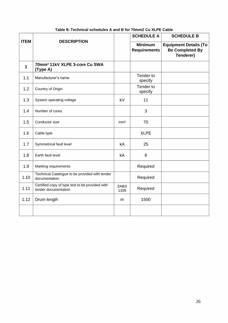
Table 8: Technical schedules A and B for 70mm2 Cu XLPE Cable
ITEM
DESCRIPTION
SCHEDULE A SCHEDULE B
Minimum
Requirements
Equipment Details (To
Be Completed By
Tenderer)
1 70mm² 11kV XLPE 3-core Cu SWA (Type A)
1.1 Manufacturer’s name Tender to
specify
1.2 Country of Origin Tender to
specify
1.3 System operating voltage kV 11
1.4 Number of cores 3
1.5 Conductor size mm² 70
1.6 Cable type XLPE
1.7 Symmetrical fault level kA 25
1.8 Earth fault level kA 8
1.9 Marking requirements Required
1.10 Technical Catalogue to be provided with tender
documentation Required
1.11 Certified copy of type test to be provided with
tender documentation SABS 1339 Required
1.12 Drum length m 1500
Page 27
27
Table 9: Deviation schedule for 70mm2 Cu XLPE Cable
Any deviations offered to this specification shall be listed below with reasons for deviation. In
addition, evidence shall be provided that the proposed deviation will at least be more cost-
effective than that specified.
ITEM PROPOSED DEVIATION
Page 28
28
SPECIFICATION FOR DIRECT BURIAL PROTECTIVE SLEEVE FOR FIBRE
OPTIC CABLES
Introduction
The protective sleeve will be used to provide a ready means of drawing fiber optic cables
under streets and pavements, and to afford protection to the fiber optic cables that will be
subject to loads due to heavy transport passing on the road above.
Scope
This specification covers the requirements for flexible protective HDPE sleeve for fiber optic
cables.
Normative references
The following documents contain provisions that, through reference in the text, constitute
requirements of this specification. All standards and specifications are subject to revision, and
parties to agreements based on this specification are encouraged to investigate the possibility
of applying the most recent editions of the documents listed below.
SANS 1222: Classification of degrees of protection provided by enclosures.
NRS 088-2: Duct and direct-buried underground fiber-optic cable, Part 2: Installation
guidelines
Requirements
Type
The protective sleeve shall:
a) Be constructed from high density polyethylene (HDPE);
b) Be yellow in colour;
c) Be supplied with pre-installed pilot rope, except if fibre optic cable can be blown
through the sleeve by means of a compressor;
d) Be in a coil of 300m in length;
e) Have a nominal outside diameter of 40 mm, with a tolerance of -0 / +0.3 mm;
f) Have an internal diameter of 33 mm;
g) Be supplied with a knock on end caps at either end of the sleeve; and
h) Be suitable for normal duty use (direct burial).
6.4.1 Construction
The protective sleeve shall:
a) Contain the highest quality virgin polymer;
Page 29
29
b) Have a bore that is true and smooth;
c) Contain no recycled or poor-quality polymer material;
d) Have an ultra-slippery silicon co-extruded bore; and
e) The length shall be continuous with no welds or joints.
6.4.2 Flexibility
The protective sleeve shall be flexible to facilitate the installation of the sleeve around
immovable objects.
6.4.3 Friction
The protective sleeve shall have a low co-efficient of friction of less than 0,1 to accommodate
the easy draw (or blow) of fiber optic cables through the sleeve.
6.4.4 Jointing
Jointing of the protective sleeve shall be done by means of standard compression couplings
which shall have an IP 66 rating as per SANS 1222 and shall have a pressure rating of 10
bar.
6.4.5 Bending Radius
The minimum bending radius shall be 10 times the outside diameter of the sleeve.
Physical properties
Impact
The protective sleeve shall exhibit no signs of splits and cracks when conditioned at -5 ºC for
2 hours and subject to an impact of 5 kg falling from 1 m drop height.
6.5.1 Pressure rating
The direct buried sleeves shall have a pressure rating of 10 bar.
6.5.2 Ultra violet
The protective sleeve, although intended to be buried underground, shall be UV resistant for
up to one year for storage purposes.
Page 30
30
End caps
End caps for sealing the open ends of sleeves already laid in the ground, but not yet installed
with fiber optic cable, shall be provided for both ends of the sleeve. The end caps shall fit
securely into the sleeve ends and hold the pilot rope captive.
Pilot rope
The polypropylene pilot rope shall be pre-installed in the sleeve.
The pilot rope shall have a breaking strain of 100 kg.
Marking
Information
All protective sleeves shall be clearly printed at 1 meter intervals with the following:
a) The manufacturer’s trademark or name, b) Outer and inner diameter, and c) The name “Greater Tzaneen Municipality”.
6.8.1 Print
The protective sleeve shall be marked with black lettering.
The numbers and characters shall be 4 mm in height.
6.8.2 Packaging
All flexible protective sleeves shall be securely supplied in coils of 300m.
The ends of the protective sleeve shall be sealed to prevent ingress of water.
Each coil shall have a waterproof label attached with the following information:
a) product code; b) length of the sleeve in meters; c) total mass
Documentation
Documentation shall be submitted in a technical catalogue format. The catalogue shall specify
the protective sleeve sizes, dimensions, reference number, and other products and
accessories.
Table 10: Technical schedules A and B of 40mm sleeve for fibre optic cables
Page 31
31
ITEM
DESCRIPTION
SCHEDULE A SCHEDULE B
Minimum
Requirements
Equipment Details (To
Be Completed By
Tenderer)
1 40mm sleeve for fibre optic cables
1.1 Manufacturer Tender to
specify
1.2 Material of flexible sleeve HDPE
1.3 Colour Yellow
1.4 Pilot string or draw-wire supplied Yes/No
Yes
1.5 Outside diameter mm 40 mm
1.6 End caps on both ends Yes/No
Yes
1.7 Constructed of high quality polymer Yes/No
Yes
1.8 Does the sleeve contain an ultra-slippery
silicon bore Yes/No
Yes
1.9 Minimum bending radius of sleeve 10d
1.10 Is the sleeve impact resistant? Yes/No
Yes
1.11 Pressure rating of the sleeve bar 10 bar
1.12 Is the sleeve UV protected? Yes/No
Yes
1.13 Are end caps supplied? Yes/No
Yes
1.14 Breaking strain of the pilot rope kg 100 kg
1.15 Do the markings on the sleeve comply? Yes/No
Yes
1.16 Does the packaging comply? Yes/No
Yes
1.17 Are the ends sealed? Yes/No
Yes
2 40mm coupling compression for fibre optic
2.1 Manufacturer Tender to
specify
2.2 Material of compression coupling Tender to
specify
Page 32
32
ITEM
DESCRIPTION
SCHEDULE A SCHEDULE B
Minimum
Requirements
Equipment Details (To
Be Completed By
Tenderer)
2.3 IP rating of compression coupling IP 66
2.4 Pressure rating bar 10 bar
Page 33
33
Table 11: Deviation schedule of 40mm sleeve for fibre optic cables
Any deviations offered to this specification shall be listed below with reasons for deviation. In
addition, evidence shall be provided that the proposed deviation will at least be more cost-
effective than that specified.
ITEM PROPOSED DEVIATION
Page 34
34
SPECIFICATION FOR SINGLE MODE DUCT FIBRE OPTIC CABLE
General
New cable differential protection relays will be installed between the following substations:
• Existing Emfuleni’s Vesco 88/11kV substation and New VUT Switching substation
(6 diff relays)
Fiber optic cable will be used for communication purposes between two differential relays.
Fiber optic ducting will be installed, with manholes for splicing purposes.
Normative references
The following documents contain provisions that, through reference in the text, constitute
requirements of this specification. All standards and specifications are subject to revision, and
parties to agreements based on this specification are encouraged to investigate the possibility
of applying the most recent editions of the documents listed below:
NRS 088-1: 2007, Duct and direct buried underground fiber optic cable. Part 1: Product
specification.
NRS 088-2: 2007, Duct and direct buried underground fiber optic cable. Part 2: Installation
guidelines.
EIA/TIA 598-C, Optical fiber cable color coding.
ISO 4892-3, Plastics – Methods of exposure to laboratory light sources – Part 3: Fluorescent
UV lamps.
NRS 081, Single-mode non-dispersion shifted optical fibers.
SANS 1411-6:2001, Materials of insulated electric cables and flexible cords – Part 6: Armour.
SANS 1411-7:2003, Materials of insulated electric cables and flexible cords – Part 7:
Polyethylene (PE).
SANS 60793-2-50/IEC 60793-2-50, Optical fibers – Part 2-50: Product specifications –
Sectional specification for class B single-mode fibers.
SANS 60794-1-2:2003/IEC 60794-1-2:2003, Optical fiber cables – Part 1-2: Generic
specification – Basic optical cable test procedures.
SANS 10198-8, The selection, handling and installation of electric power cables of rating not
exceeding 33 kV − Part 8: Cable laying and installation.
SANS 10340-2, Installation of telecommunication cables − Part 2: Outdoor fiber optic cables.
SANS 60793-1-40/IEC 60793-1-40: 2001, Optical fibers – Part 1-40: Measurement methods
and test procedures – Attenuation.
Testing of fibre optic cables
Testing will be done as per NRS 088, and will include the following:
Page 35
35
• Optical test
• Longitudinal water penetration
• Sheath UV withstand test
• Tensile strength
• Crush resistance
• Cable bending
• Cable twist (torsion)
• Impact resistance
• Temperature cycling
• Compound flow (drip)
It should be noted that it is deemed mandatory for the Contractor to test the fiber optic cable
after delivery, before installation. This is required should the cable be faulty after installation.
All tests above should be incorporated into the tendered rate.
Marking, labelling and packaging
As per NRS 088-1.
Installation of fibre optic cable
As per NRS 088-2. Note paragraph 4.3.5 (Trench floor) and 4.3.6 (Backfilling of trenches).
The particle size of the soil is not allowed to be more than 12mm.
Page 36
36
Table 12: Technical schedules A and B specification for single mode duct fibre optic cable
ITEM
DESCRIPTION
SCHEDULE A SCHEDULE B
Minimum
Requirements
Equipment Details (To
Be Completed By
Tenderer)
Number of fibres 4
Type of fiber (e.g., type B 1.1 single
mode fiber as in NRS 081) Single mode
Armouring required No
Type of armouring (CST or SWA) N/A
Details of fibre colour coding As in EIA/TIA
598-C
Measures taken to prevent water ingress XXXXXXXXX
Toxicity and dermatological safety Yes
Cable tension for 0,2 % fiber strain N XXXXXXXXX
Availability of type test reports. If not
available, specify date when available XXXXXXXXX
Wound length of cable on drum m XXXXXXXXX
Treated wooden drum required Yes
Cable construction drawing number XXXXXXXXX
Cable mass per unit length kg / km
XXXXXXXXX
Effective group index of refraction at
1 310 nm/1 550 nm XXXXXXXXX
1310 nm =
1550 nm =
Page 37
37
Table 13: Deviation schedule specification for single mode duct fibre optic cable
Any deviations offered to this specification shall be listed below with reasons for deviation. In
addition, evidence shall be provided that the proposed deviation will at least be more cost-
effective than that specified.
ITEM PROPOSED DEVIATION
Page 38
38
SPECIFICATION FOR MINIATURE SUBSTATIONS
Miniature substation
The following miniature substation sizes shall comply with the following specification:
• 315kVA 11/400V
• 500kVA 11/400V
• 600kVA 11/400V
General
The mini sub shall be suitable for outdoor purposes and comply with the requirement for
coastal condition.
Descriptions
The mini sub shall consist of three compartments ie:
• Medium voltage switchgear compartment
• Transformer compartment
• Low Voltage switchgear compartment
All live terminals shall be tamper proof.
The LV compartment shall consist of 2 sections ie:
• The front section containing meter, busbars, circuit breakers and cable gland plate.
Page 39
39
• The side section making provision for streetlight equipment and cables.
• Access to the HV and LV compartments shall only be possible by unlocking the doors.
• The miniature substation shall be constructed of 3 CR 12 sheet metal.
• The final colour finish shall be in SABS C12 “Avocado”.
• An earth bar of nominal cross section area of 70mm minimum shall be fitted inside the
mini sub extending across the length of each of the medium voltage transformer and low
voltage compartments.
The following notices shall be riveted onto the outside of the miniature substation:
• Danger sign in accordance with figure 3 of SABS1029 with in addition the word “Ingozi”
below the word “Gevaar” to be fitted in front of the transformer compartment.
• The letters HV/S on the door of the medium voltage compartment.
• The letters LV/S on the door of the low voltage compartment.
• The word street lighting on the door of the street lighting panel.
• Lifting lugs suitable for hoisting the complete Mini sub shall be provided concerted under
the removable roof.
• All ventilation openings shall have a deflecting plate and shall be suitable “vermin proof”.
Medium Voltage Compartment
• The ring switches shall have a continuous rating of 630 Amp. A fault making of 250 MVA
of 11 kV and withstand a fault current of 25 kA for 3 seconds.
• The fuse unit must have the characteristics to protect the transformer under all conditions.
• Each unit shall be supplied with appropriate labels to indicate the circuits.
• Switchgear shall be supplied with cable end boxes suitable for XLPE cables. Cable boxes
to be earthed to main earth bar.
Transformer in transformer compartment.
• Three phase double wound transformer with laminated core to SABS 780.
• The load will consist of resistive and inductive circuits.
• The no-load voltage is 11000/420 volt.
• DYN 11 Vector group.
Page 40
40
• 50 Hz Frequency
• Supplied with and external operated off-load tap change to alter the secondary voltage in
5 steps from 95% - 105%. The tap changer shall be insulated for line voltage between
tapping’s and provision shall be made to eliminate unintentional operation of the tap
changer. The tap change switch shall be housed in the low voltage compartment in an
accessible position.
• Hermetically sealed.
• The neutral shall be coupled to the earth bar directly.
• The three primary bushes shall be suitable for the use in a mini sub.
• The four secondary isolating bushes shall be suitable for the use in a mini sub.
• Type ONAN COOLING.
Low Voltage compartment
• The busbars shall be sized for 500 kVA and marked in the three phase colours ei: Red,
Yellow and Blue.
• The neutral busbar shall have the same cross-sectional area as the phase busbars.
• The fault capacity of the busbars, circuit breakers and other equipment are determined by
the impedance of the transformer ie: 25 KA.
• The front section of the LV compartment shall house the following equipment:
a. 400V, 5A Ennermax Electronic meter with maximum mass memory, manufactured
by Strike Technologies with test certificate - Programming will be done by Council.
b. One 25 kA MCB rated at full load current of miniature substation.
c. Mounting space must be provided for at least five LY603 25 kA HY-MAG circuit
breakers to be fitted next to each other with sufficient working space in between.
These breakers must be supplied from busbars mounted above them.
d. It shall be fitted with a cable-clamping rail over the whole length of terminations of
the outgoing cables complete with clamps for minimum 95mm x 4 core cable.
e. The distance from the rail to the top of the plinth shall be at least 75mm and not
less than 350mm between the rail and the nearest terminals of the outgoing LV
circuits.
f. An earth busbar of bare hard-drawn copper shall be provided to facilitate earthing
of cable amour and at least a cross - sectional are of 70mm and minimum width of
25mm. Centrally located holes to clear M12 bolts shall be provided at intervals of
Page 41
41
75mm along the whole length.
g. Low Voltage terminations shall be suitable for Aluminium out-going circuits.
• The side section of the LV compartment for street-lighting shall provide for the following
equipment:
a. 1 x 100 Amp 25 KA breaker (MCCB)
b. 1 x 5 Amp MCCB for protection of the contactor coil.
c. 1 x 10 Amp isolator as a “bypass” for the photo cell.
d. 3 x Single phase kWh meters.
e. 1 x 60 Amp triple pole contactor with 220V coil.
f. Cable gland plate to terminate the outgoing cables.
g. 1 x 20 Amp photo cell mounted inside the compartment behind a suitable Perspex
window.
Page 42
42
11KV METAL-CLAD SWITCHGEAR SPECIFICATION
Table 14: Technical Schedule A and B for 11kV metal-clad switchgear specification
Item Requirements
1
1.1 Ambient air temperature range °C -5 to +40
1.2 Average humidity % up to 95
1.3 Altitude (amsl) m up to 1800
1.4 Degree of pollution (SANS IEC 60815) Medium
2
2.1 Number of phases 3
2.2 Normal power frequency Hz 50
2.3 Operating Voltage kV 11
2.4 Normal Load Current A 630
2.5 Normal Busbar Rating A 1250
2.6 System voltage range pu 0,95 to 1,05
2.7 System earthing (effective/non effective) Non-effective
3
3.1 Rated Insulation Level
3.2 Lightning impulse withstand voltage kV peak
95
3.3 Short duration P.F withstand voltage kV r.m.s
25
4 Rated Withstand Currents
4.1 Short duration withstands current (3 Sec) kA r.m.s
25
4.2 Heater Size Watt 40
4.3 - Installed in Busbar compartment Yes
4.4 - Installed in Breaker compartment Yes
4.5 - Installed in Cable compartment Yes
5 Switchboard assembly
5.1 Loss of service continuity category (LSC) LSC2B
5.2 Enclosure material type Metal-Clad
5.3 Switchboard application Incomer/Feeder
Page 43
43
5.4 Interchangeable with different current rating breakers NO
5.5 Integral shutters in accordance with IEC 62271-200 Class PM
5.6 Withdrawable, pad lockable parts YES
5.7 Padlocking facility-shank diameter mm >6
5.8 Separate compartments needed for:
5.9 - Main switch Yes
5.1 - Primary busbar Yes
5.11 - Power cable/Current transformers Yes
5.12 Degree of protection by enclosures with racked in/out. IP3X
6 Internal Arc Classification
6.1 Types of accessibility to switchgear AFLR/BFL-AR
6.2 Classification test values:
6.3 - Fault current kA r.m.s
25
6.4 - Duration (AFLR / BFL-AR) ms 1000 / 200
7 Busbars
7.1 3-phase busbars Single
7.2 Bus-section/coupler device Circuit Breaker
7.3 In-services withstand parameters
7.4 - Lightning impulse withstand voltage kV peak
95
7.5 - Short duration P.F withstand voltage kV r.m.s
25
7.6 - Short duration withstand current (3 Sec) kA r.m.s
25
7.7 - Peak withstand current kA peak
25
7.8 Permissible partial discharge quantity pC < 100
8 Power Cabling
8.1 Supply of power cabling
8.2 Cabling
8.3 Installation and termination of power cable
8.4 Cable Size mm2 185
8.5 Cable Type XLPE
8.6 Cable entry and access Rear & Below
8.7 Height of cable termination from gland plate mm >600
8.8 Termination medium Air
8.9 Termination method Shrink-end
9 Termination clearances (air and bare lugs) NRS 012
9.1 Earthing via insulated glands for:
9.2 - 1 Core YES
9.3 - 3 Core NO
9 Surge Arrestor Requirements (Feeder Panel ONLY)
9.1 Position Cable termination
Page 44
44
9.2 Surge arrester earthing To be bonded to panel with
150mm2 copper (minimum)
10 Earthing Requirements
10.1 To be rated for fault making YES
10.2 Earth circuit rated at full short circuit withstand capacity YES
10.3 Rated short-time withstand r.m.s. current kA r.m.s
25
10.4 Position of bar primary Cable Side
11 Marking and labelling
11.1 Labelling as per Eskom standard DISASAAN0 YES
11.2 Label visibility During in-service
conditions
11.3 Main circuit label dimensions on front and rear of panels:
11.4 - Width (min.) mm > 150
11.5 - Height (min.) mm > 35
11.6 Main circuit label positions Front and rear of panels
(not on removable
doors)
11.7 Function label dimensions (min height) mm > 5
11.8 On, Off, Earth labels as per NRS 003 YES
11.9 Shutter labels as per NRS 003 YES
11.1 Danger Zone labelling on sides and back of panel YES
11.11 Busbar blanking plates "Busbar Do Not Remove"
12
12.1 General
12.2 Rating name plate position Front of BKR
12.3 In service withstand parameters
12.4 - Lightning impulse withstand voltage kV peak
95
12.5 - Short duration P.F withstand voltage kV r.m.s
25
12.6 - Short duration withstand current (3 Sec) kA r.m.s
25
12.7 - Peak withstand current kA peak
25
12.8
12.9 Classification (Refer to IEC 62271-100)
12.1 Electrical Endurance E2
12.11 Re-strike Performance C1
12.12
Page 45
45
12.13 Operation and function
12.14 Type of arc control method SF6 / Vacuum
12.15 Number of poles 3
12.16 Withdrawable with self-alignment device YES
Spring-charge motor ratings:
12.17 - A.C. supply voltage Vac 230
12.18 - D.C. supply voltage Vdc 110
12.19 Isolation of trip circuit, if circuit-breaker is earthed YES
12.2 Trip-free circuit-breaker operation YES
13 Coil devices
13.1 Range of operation (as applicable)
13.2 - A.C. supply voltage % 85 to 110
13.3 - D.C. supply voltage % 70 to 110
13.4 Ratings for continuous operation
13.5 - D.C. supply voltage Vdc 110
13.6 - D.C. real power (peak) W 1500
13.7 Number of trip coils required 2
13.8 Number of close coils required 1
14 Auxiliary contacts facilities (spare for Eskom use)
14.1 Duty rating
14.2 - A.C. and D.C. supply current A 10
14.3 - A.C. supply voltage Vac 230
14.4 - D.C. supply voltage Vdc 110
Page 46
46
Table 15: Deviation schedule specification for single mode duct fibre optic cable
Any deviations offered to this specification shall be listed below with reasons for deviation. In
addition, evidence shall be provided that the proposed deviation will at least be more cost-
effective than that specified.
ITEM PROPOSED DEVIATION
Page 47
47
WIRING
• All internal wiring shall generally comprise of PVC insulated stranded copper conductors
and bare stranded copper earth continuity conductors. The Electrical Contractor to note
that protective earth conductors for all computer outlets shall be green PVC insulated
stranded copper conductors.
• Only new wiring shall be used under this contract.
• Wiring shall not be drawn into conduit until the conduit installation has been completed,
fitted with bushes and all moisture and debris has been removed.
• No joints of any kind shall be permitted in wiring.
• No more than one (1) single - or one (1) three-phase circuit may be drawn into any conduit.
• No “surfix” and/or “twin & earth” wiring will be accepted.
The following minimum conductor sizes shall be used:
Table 16: Minimum conductor sizes
Circuit Minimum conductor (size)
Phase (mm²) Earth (mm²)
Lighting 1.5 1.5
Socket outlet 4 4
Geyser 4 4
Hydro boil 4 4
Air conditioning unit 4 4
Extraction fan 4 4
• Wiring for information and communication services i.e. data and telephone, shall be
supplied, installed and terminated by others. The Electrical Contractor shall only be
responsible for provision of all wireways for such installations. Steel draw wires shall also
be provided by the Electrical Contractor in all conduit and other wireways provided for all
electronic services as indicated on the relevant drawings.
TELEPHONE AND DATA INSTALLATION
Page 48
48
• The Electrical Contractor shall also be responsible for provision of all wireways for data
and telephone systems
• Galvanised draw wire (2,5mm diameter) shall be installed in all telephone and data
conduits. All information and communication outlet points shall be interlinked by means
of 32mm and 25mm diameter conduit which via the roof space
EARTHING AND BONDING
• The Electrical contractor is to ensure that the installations covered in this document are
effectively earthed and bonded in accordance with the requirements of SABS 0142.
• All hot and cold water and waste metal pipes are to be effectively bonded by means of
12,5 mm x 1,6 mm solid or perforated copper tape (not wire), clamped by means of
brass bolts and nuts. The tape is to be fixed to walls by means of rounded brass screws
at intervals not exceeding 150 mm.
• Metal cable supports and others structures e.g., aerials shall be bonded by means of
green insulated copper earth conductor of 16mm2 minimum size.
LIGHTNING PROTECTION
• A provisional sum has been allowed in the bills of quantities for supply and installation of
an earthing and lightning protection system by a Specialist Sub-Contractor. The design
and installation shall be based on results of the soil resistivity tests to be conducted by the
specialist to be appointed as part of this sub-contract.
• Lightning protection shall be carried out in accordance to SANS 10313 – “Protection
against lightning - Physical damage to structures and life hazard”
• The system shall comprise of air terminations, down conductors, testing joints and earth
electrodes. All metallic projections on or above the main surface of the roof structure
shall be bonded to the protective system and shall form part of the air termination
network.
SECURITY LIGHTING GENERAL
• Security lighting shall be provided as part of this contract around the building.
Page 49
49
• Light fittings shall be supplied and installed complete with lamps, ballasts, control gear,
diffusers, mounting facilities, etc., as applicable. All fittings shall be new and unused and
shall be delivered to site as packed by the supplier.
• The permanent luminaires intended for installation shall not be used for temporary lighting
during construction. The certificate of completion for the installation will not be finalised
unless all light fittings and lamps are in working order.
• All fixing screws, nuts, bolts and washers shall be of stainless-steel manufacture.
Luminaires shall be installed so as to ensure manufacturer’s IP classification is still valid.
LUMINAIRE SPECIFICATION
• All luminaires shall bear the SABS mark. Luminaires shall be provided complete with
lamps and drivers
• Security and area lighting shall be provided by means of LED and/or CFL luminaires and
installed at positions shown on the relevant drawings.
• The post-top light poles shall be 6m high (mounting height) with 76mm in diameter at the
top, manufactured from hot deep galvanised steel. Mounting brackets shall also be hot
dipped galvanised.
• All external luminaires shall have protection rating of IP 65 or better.
Distribution board equipment shall be connected in such an order that the load is balanced
across all three phases.
SITE TESTS AND COMMISSIONING
• It shall be the responsibility of the Electrical Contractor to provide all labour, accessories
and properly calibrated and certified measuring instruments necessary for all the tests
required under this contract.
• Prior to beginning any aspect of commissioning, the contractor shall present for the
Engineer’s review/approval, two copies of a complete commissioning procedures manual
including checklists. The relevant checklists shall be utilised and formally signed off as
part of the commissioning phase.
• Preparation of commissioning report shall include, but not necessarily limited to:
• Manufacturer’s operating, servicing and maintenance manuals for each and every
individual item of plant installed.
Page 50
50
• Inventory for the items of mechanical/electrical plant(s) and or equipment that shall be for
installation in the project.
• The following minimum site tests shall be carried out by the electrical contractor and the
results presented to the Engineer:
• Insulation resistance between all conductors and earth
• Insulation resistance between all conductors and neutral
• Insulation resistance between all 3 phase conductors
• Resistance of earth path between the main earth bar, all exposed conductive parts
of the installation and distribution boards
• Polarity of light switches and socket outlets
• Earth leakage protection
• Phase rotation of three phase circuits
• After submission of the test results, the Electrical contractor shall notify the Engineer that
the installation is complete, tested and in working order. The Client and/or the Engineer
will witness the re-testing of the installation.
MAINTENANCE PERIOD
• The equipment and installation supplied under this contract shall be guaranteed for a
period of twelve months from date of completion of the whole project of the Contract
Works. The tender price shall include for the above.
• The maintenance period will be for a period of twelve months, calculated from the date
the complete installation has been taken over by the Client. Payment of the full amount
of the retention money will be affected after the lapse of the maintenance period, provided
the installation has been in satisfactory working order during this period. The Electrical
contractor shall be responsible for the replacement of all faulty electrical equipment
supplied and installed as part of this Sub-Contract, including blown or faulty lamps during
the maintenance period.
BIDDERS FULL NAME/S BIDDERS SIGNATURE DATE