2 Progettazione & Sviluppo / Design & Development 3
3 Area di Mercato / Market area 4
3.1 Istallazioni nel Mondo / Installations in the world 5
4 Serie VDA / VDA series 6
5 Serie SPC / SPC series 9
6 Post combustione / Post-combustion 11
7 Teste di Combustione / Combustion heads 14
8 I Nostri Bruciatori nel Mondo / Our burners in the world 15
9 Dove Siamo / Where we are 16
2
1. INTRODUZIONE INTRODUCTION
PRODUZIONE PRODUCTION
La I.T.F. SNC è una azienda nata nel 2012
che opera nel settore termotecnico.
In particolare, utilizzando la competenza
tecnica dei propri addetti, acquisita nel
corso di molti anni di lavoro presso una
azienda leader del settore, si propone di
continuare ad offrire tecnologie e prodotti
di affermata qualità.
I.T.F. SNC is a company founded in 2012 that operates in the thermotechnical sector. In particular, using the technical expertise of its employees, acquired over many years of work at a leading company in the industry, it is proposed to continue offering technologies and products of established quality.
Bruciatori in vena d’aria a gas (naturale, GPL, miscelato) progettati per funzionare all’interno di un flusso d’aria. Sono costituiti da “moduli” componibili che, secondo la potenza necessaria e l’applicazione richiesta, permettono di utilizzare il sistema in molteplici tipologie di impianto. Il grande rapporto di regolazione, cioè la possibilità di variare la portata termica da 1 ÷ 10 - 1 ÷ 20 - 1 ÷ 40, assicura rapidità di intervento, precisione di lavoro, limitata dispersione termica, riduzione di emissioni. In breve “minor consumo e alto rendimento”. Bruciatori “compatti” a gas (naturale, GPL, miscelato) e gasolio dove la testa di combustione a grande rapporto di regolazione da 1 ÷ 10 e 1 ÷ 25, è provvista di ventilatore aria comburente, rampa valvole gas, modulatore di portata e quadro di comando già assemblati e pronti per l’installazione. Teste di combustione a media e alta velocità a gas (naturale, GPL) con aria di combustione fredda o surriscaldata per recupero termico utilizzate su applicazioni industriali.
Gas airflow burners (natural, LPG, mixed) designed to operate within an airflow. They are made up of modular "modules" which, according to the required power and the required application, allow the system to be used in many types of systems. The large adjustment ratio, that is the possibility of varying the thermal capacity from 1 ÷ 10 - 1 ÷ 20 - 1 ÷ 40, ensures quick intervention, precision of work, limited heat loss, reduction of emissions. In short "lower consumption and high yield”. "Compact" gas burners (natural, LPG, mixed) and gas oil where the combustion head with a high regulation ratio of 1 ÷ 10 and 1 ÷ 25, is equipped with combustion air fan, gas valve ramp, flow modulator and control panel controls already assembled and ready for installation. Medium and high speed combustion heads with gas (natural, LPG) with cold or overheated combustion air for heat recovery used on industrial applications.
3
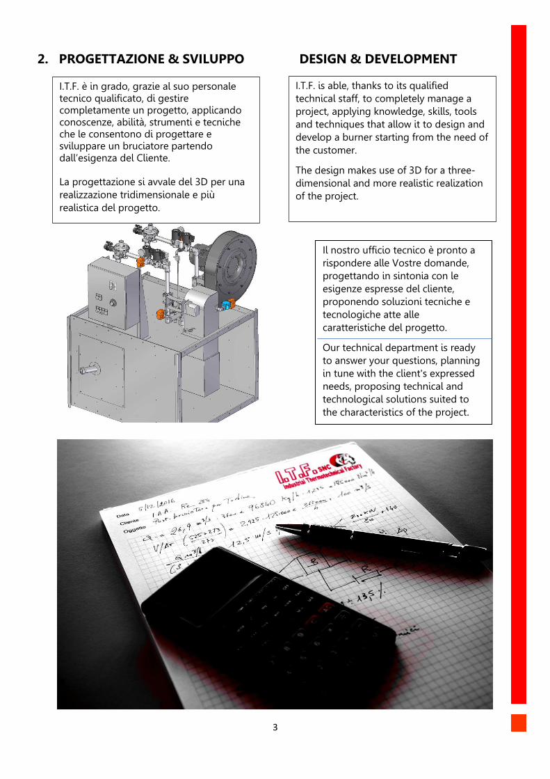
2. PROGETTAZIONE & SVILUPPO DESIGN & DEVELOPMENT
Il nostro ufficio tecnico è pronto a
rispondere alle Vostre domande,
progettando in sintonia con le
esigenze espresse del cliente,
proponendo soluzioni tecniche e
tecnologiche atte alle
caratteristiche del progetto.
Our technical department is ready
to answer your questions, planning
in tune with the client's expressed
needs, proposing technical and
technological solutions suited to
the characteristics of the project.
I.T.F. is able, thanks to its qualified
technical staff, to completely manage a
project, applying knowledge, skills, tools
and techniques that allow it to design and
develop a burner starting from the need of
the customer.
The design makes use of 3D for a three-
dimensional and more realistic realization
of the project.
I.T.F. è in grado, grazie al suo personale tecnico qualificato, di gestire completamente un progetto, applicando conoscenze, abilità, strumenti e tecniche che le consentono di progettare e sviluppare un bruciatore partendo dall’esigenza del Cliente. La progettazione si avvale del 3D per una
realizzazione tridimensionale e più
realistica del progetto.
4
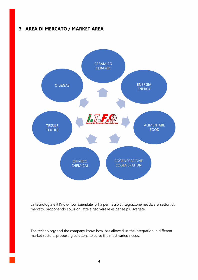
3 AREA DI MERCATO / MARKET AREA
La tecnologia e il Know-how aziendale, ci ha permesso l’integrazione nei diversi settori di
mercato, proponendo soluzioni atte a risolvere le esigenze più svariate.
The technology and the company know-how, has allowed us the integration in different
market sectors, proposing solutions to solve the most varied needs.
CERAMICO CERAMIC
ENERGIA ENERGY
ALIMENTARE FOOD
COGENERAZIONE COGENERATION
CHIMICO CHEMICAL
TESSILE TEXTILE
OIL&GAS
5
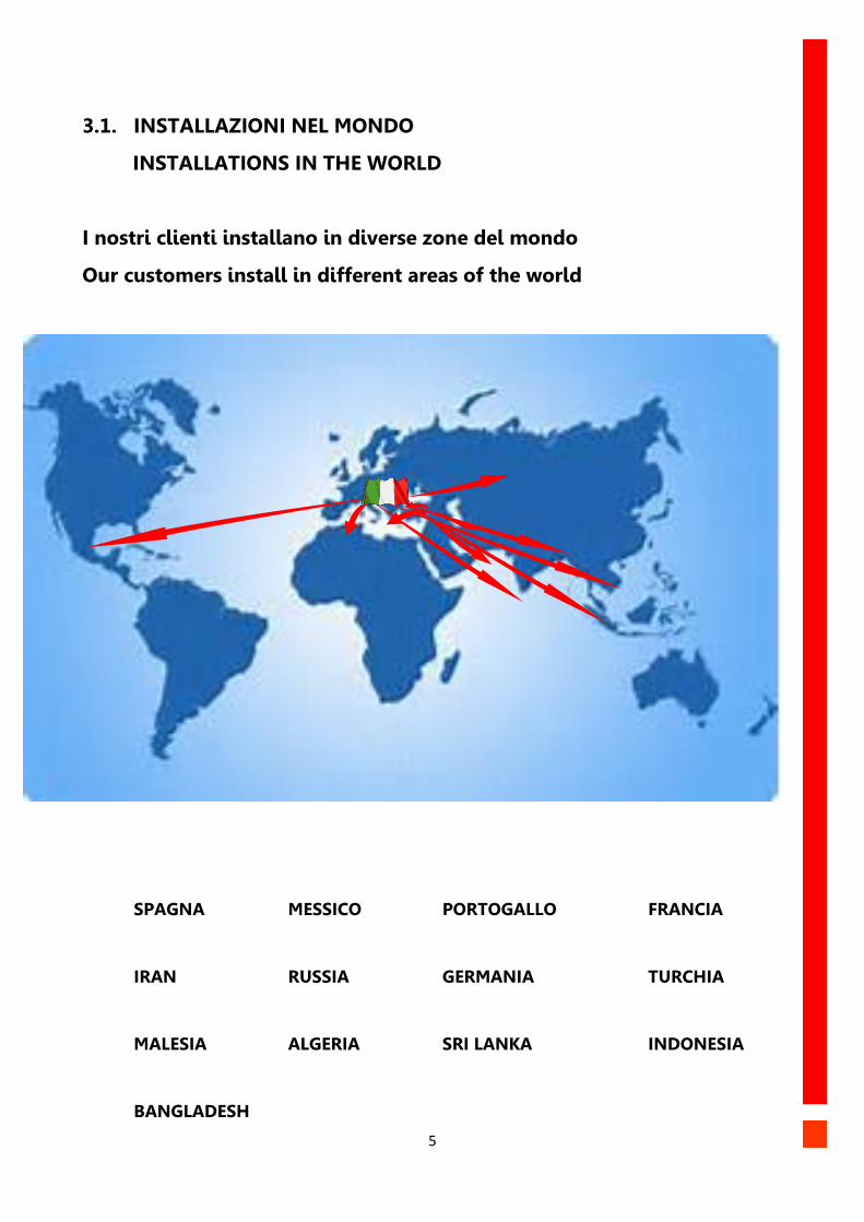
3.1. INSTALLAZIONI NEL MONDO
INSTALLATIONS IN THE WORLD
I nostri clienti installano in diverse zone del mondo
Our customers install in different areas of the world
SPAGNA MESSICO PORTOGALLO FRANCIA
IRAN RUSSIA GERMANIA TURCHIA
MALESIA ALGERIA SRI LANKA INDONESIA
BANGLADESH
6
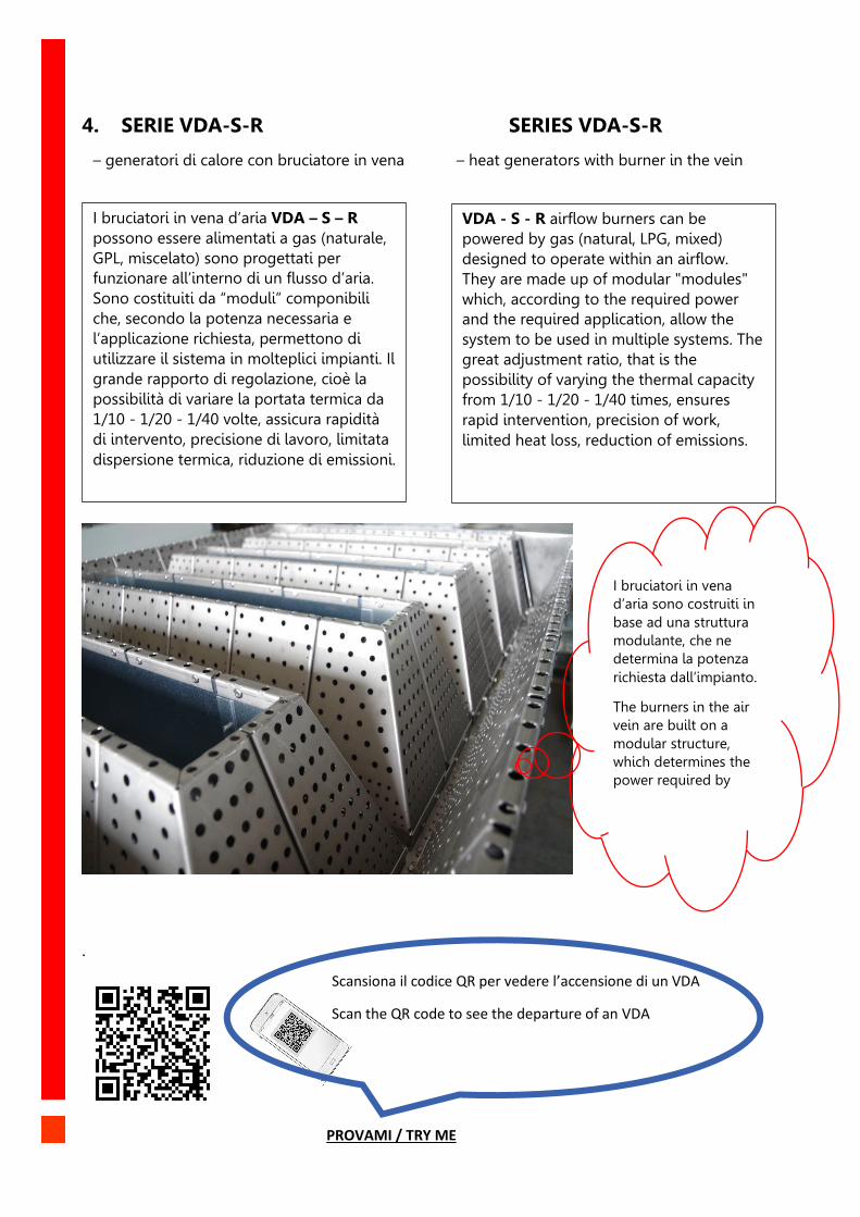
4. SERIE VDA-S-R SERIES VDA-S-R
– generatori di calore con bruciatore in vena – heat generators with burner in the vein
.
Scansiona il codice QR per vedere l’accensione di un 20 MW
PROVAMI / TRY ME
Scansiona il codice QR per vedere l’accensione di un VDA
Scan the QR code to see the departure of an VDA
I bruciatori in vena d’aria VDA – S – R
possono essere alimentati a gas (naturale,
GPL, miscelato) sono progettati per
funzionare all’interno di un flusso d’aria.
Sono costituiti da “moduli” componibili
che, secondo la potenza necessaria e
l’applicazione richiesta, permettono di
utilizzare il sistema in molteplici impianti. Il
grande rapporto di regolazione, cioè la
possibilità di variare la portata termica da
1/10 - 1/20 - 1/40 volte, assicura rapidità
di intervento, precisione di lavoro, limitata
dispersione termica, riduzione di emissioni.
VDA - S - R airflow burners can be
powered by gas (natural, LPG, mixed)
designed to operate within an airflow.
They are made up of modular "modules"
which, according to the required power
and the required application, allow the
system to be used in multiple systems. The
great adjustment ratio, that is the
possibility of varying the thermal capacity
from 1/10 - 1/20 - 1/40 times, ensures
rapid intervention, precision of work,
limited heat loss, reduction of emissions.
I bruciatori in vena
d’aria sono costruiti in
base ad una struttura
modulante, che ne
determina la potenza
richiesta dall’impianto.
The burners in the air
vein are built on a
modular structure,
which determines the
power required by the
system
7
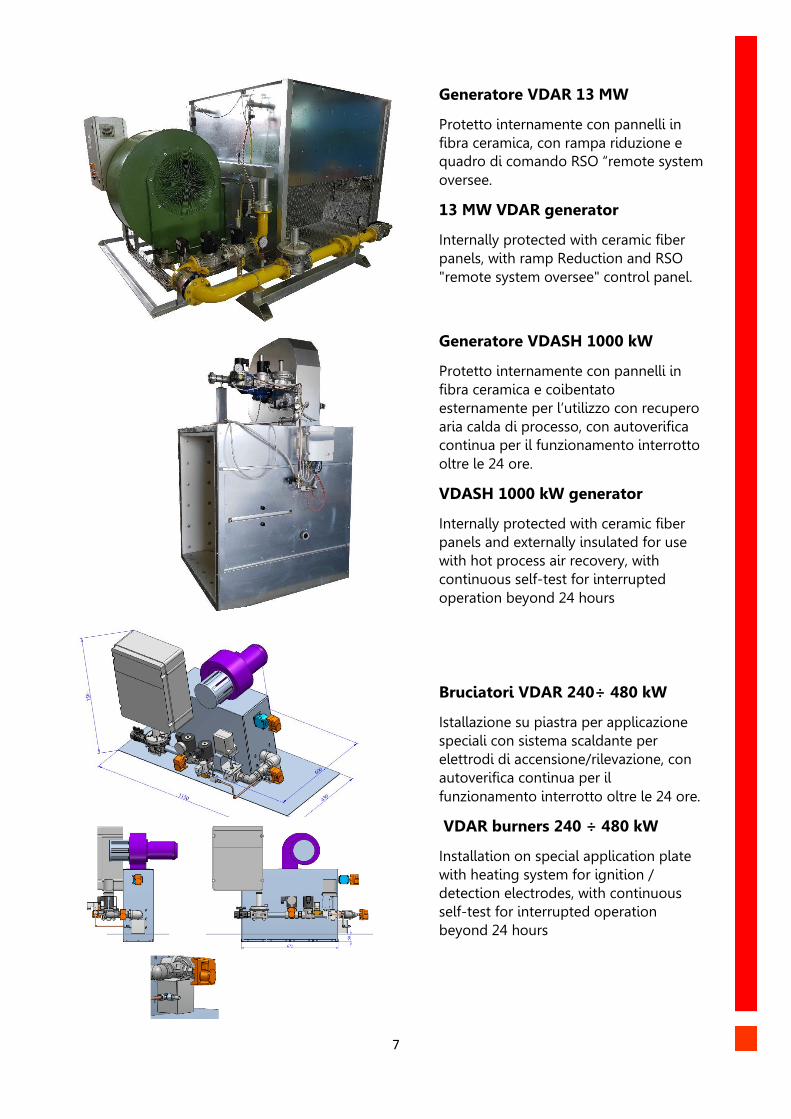
Generatore VDAR 13 MW
Protetto internamente con pannelli in
fibra ceramica, con rampa riduzione e
quadro di comando RSO “remote system
oversee.
13 MW VDAR generator
Internally protected with ceramic fiber
panels, with ramp Reduction and RSO
"remote system oversee" control panel.
Generatore VDASH 1000 kW
Protetto internamente con pannelli in
fibra ceramica e coibentato
esternamente per l’utilizzo con recupero
aria calda di processo, con autoverifica
continua per il funzionamento interrotto
oltre le 24 ore.
VDASH 1000 kW generator
Internally protected with ceramic fiber
panels and externally insulated for use
with hot process air recovery, with
continuous self-test for interrupted
operation beyond 24 hours
Bruciatori VDAR 240÷ 480 kW
Istallazione su piastra per applicazione
speciali con sistema scaldante per
elettrodi di accensione/rilevazione, con
autoverifica continua per il
funzionamento interrotto oltre le 24 ore.
VDAR burners 240 ÷ 480 kW
Installation on special application plate
with heating system for ignition /
detection electrodes, with continuous
self-test for interrupted operation
beyond 24 hours
8
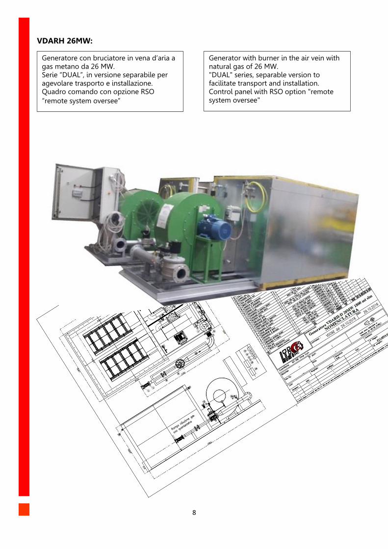
VDARH 26MW:
Generatore con bruciatore in vena d’aria a gas metano da 26 MW. Serie “DUAL”, in versione separabile per agevolare trasporto e installazione. Quadro comando con opzione RSO
“remote system oversee”
Generator with burner in the air vein with natural gas of 26 MW. "DUAL" series, separable version to facilitate transport and installation. Control panel with RSO option "remote system oversee"
9
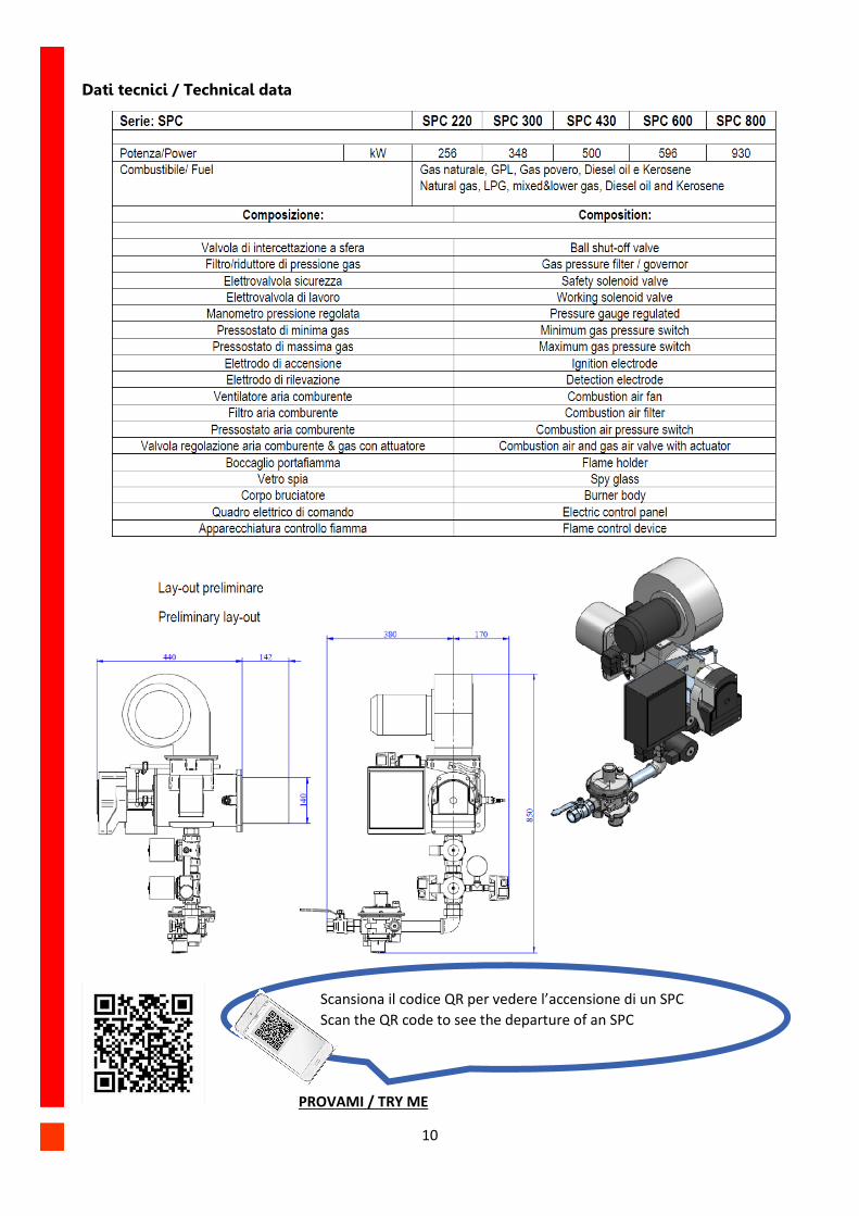
5. SERIE SPC SPC SERIES
_ Serie Piccola combustione _ Small Combustion Series
La serie SPC abbraccia una potenzialità
compresa tra 256 kW e 930 kW con un
campo di applicazione che spazia dalle
caldaie con focolare in pressione ai
generatori d’aria calda, di vapore o di
acqua surriscaldata, forni per trattamenti
termici di media potenzialità ed essiccatoi
per diverse tipologie di prodotti trattati:
tessili, cartari, chimici, manifatturieri,
alimentari ecc. La facilità di installazione
unita alla sicurezza di un prodotto
conforme alle Direttive Europee e
costantemente testato presso il nostro
laboratorio, rendono i bruciatori della serie
SPC macchine complete e affidabili.
The SPC series located potential between 256 kW and 930 kW has many field of application like boilers with pressurized combustion chamber to hot air dryers, steam or superheated water generators, to medium-temperature heat treatment owens. The simple execution combined with safety product & compliance with the European Directives rules and constantly tested in our laboratory, assure ours burners in a complete and reliable products.
Descrizione: Tutti i bruciatori sono dotati del ventilatore dell’aria comburente. Il quadro elettrico è completo di apparecchiatura elettronica di controllo fiamma. La logica di controllo è adattabile secondo le specifiche esigenze dell’impianto. Sono disponibili versioni per gas naturale, GPL, gas povero, gasolio e kerosene: alimentazione ad aria ambiente o con aria calda per recupero di calore. Regolazione progressiva, rapporto 1/10 – 1/20 Pressione alimentazione standard min. 200
mbar – max 500mbar: sono disponibili
equipaggiamenti con pressioni diverse.
Tensione di alimentazione quadro V230-400/50-60Hz Camera di combustione in pressione,
depressione o bilanciata da precisare in
sede di commessa.
Applicazioni / Utilizzo: Trattamento Superfici: Essiccatoi, forni vernici, forni per invecchiamento, trattamento in generale. Ceramico Laterizio: Essiccatoi a rulli a tunnel, intermittenti e continui Tessile: Asciugatoi Cartario: Generatori per cappe yankee per asciugatura Alimentare: Essiccazione in generale e tostatrici per caffè Impianti post combustione.
Description: All burners are equipped with a combustion air fan. The electrical panel is completed by electronic control flame panel. The control system are adapted according to specific system project. Versions are available with natural gas, LPG, lower gas (coke & similar), diesel oil and kerosene: supply to combustion air by ambient or with hot air for heat recovery. Progressive regulation ratio 1/10 - 1/20 Min. Supply pressure 200 mbar - max 500mbar and others pressure by request. Panel power supply voltage V230-400 / 50-60Hz Combustion chamber with pressure process positive/negative & balanced to specify in order.
Applications / Use: Surface treatment: Dryers, paint ovens, aging ovens, general treatment Ceramic Brick: Tunnel, intermittent and continuous roller driers Textiles: Dryers Paper: Generators for Yankee hoods for drying Food: general drying and coffee roasters Post-combustion plants.
10
Dati tecnici / Technical data
Scansiona il codice QR per vedere l’accensione di un SPC
Scan the QR code to see the departure of an SPC
PROVAMI / TRY ME
11
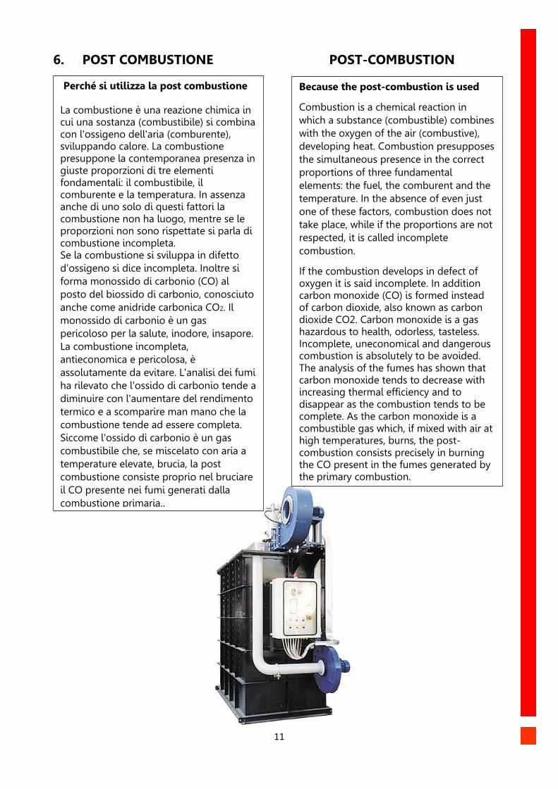
6. POST COMBUSTIONE POST-COMBUSTION
Perché si utilizza la post combustione La combustione è una reazione chimica in cui una sostanza (combustibile) si combina con l'ossigeno dell'aria (comburente), sviluppando calore. La combustione presuppone la contemporanea presenza in giuste proporzioni di tre elementi fondamentali: il combustibile, il comburente e la temperatura. In assenza anche di uno solo di questi fattori la combustione non ha luogo, mentre se le proporzioni non sono rispettate si parla di combustione incompleta. Se la combustione si sviluppa in difetto
d'ossigeno si dice incompleta. Inoltre si
forma monossido di carbonio (CO) al
posto del biossido di carbonio, conosciuto
anche come anidride carbonica CO2. Il
monossido di carbonio è un gas
pericoloso per la salute, inodore, insapore.
La combustione incompleta,
antieconomica e pericolosa, è
assolutamente da evitare. L'analisi dei fumi
ha rilevato che l'ossido di carbonio tende a
diminuire con l'aumentare del rendimento
termico e a scomparire man mano che la
combustione tende ad essere completa.
Siccome l'ossido di carbonio è un gas
combustibile che, se miscelato con aria a
temperature elevate, brucia, la post
combustione consiste proprio nel bruciare
il CO presente nei fumi generati dalla
combustione primaria..
Because the post-combustion is used
Combustion is a chemical reaction in
which a substance (combustible) combines
with the oxygen of the air (combustive),
developing heat. Combustion presupposes
the simultaneous presence in the correct
proportions of three fundamental
elements: the fuel, the comburent and the
temperature. In the absence of even just
one of these factors, combustion does not
take place, while if the proportions are not
respected, it is called incomplete
combustion.
If the combustion develops in defect of oxygen it is said incomplete. In addition carbon monoxide (CO) is formed instead of carbon dioxide, also known as carbon dioxide CO2. Carbon monoxide is a gas hazardous to health, odorless, tasteless. Incomplete, uneconomical and dangerous combustion is absolutely to be avoided. The analysis of the fumes has shown that carbon monoxide tends to decrease with increasing thermal efficiency and to disappear as the combustion tends to be complete. As the carbon monoxide is a combustible gas which, if mixed with air at high temperatures, burns, the post-combustion consists precisely in burning the CO present in the fumes generated by the primary combustion.
12
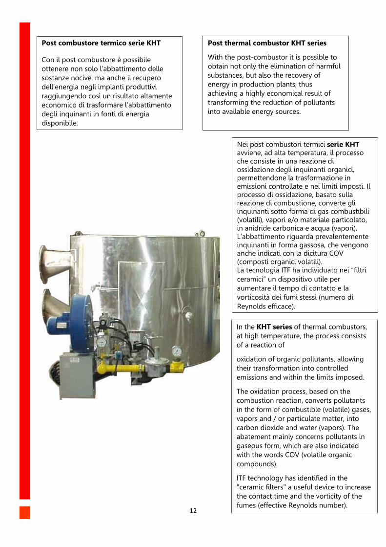
Post combustore termico serie KHT Con il post combustore è possibile
ottenere non solo l’abbattimento delle
sostanze nocive, ma anche il recupero
dell’energia negli impianti produttivi
raggiungendo così un risultato altamente
economico di trasformare l’abbattimento
degli inquinanti in fonti di energia
disponibile.
Post thermal combustor KHT series
With the post-combustor it is possible to
obtain not only the elimination of harmful
substances, but also the recovery of
energy in production plants, thus
achieving a highly economical result of
transforming the reduction of pollutants
into available energy sources.
Nei post combustori termici serie KHT avviene, ad alta temperatura, il processo che consiste in una reazione di ossidazione degli inquinanti organici, permettendone la trasformazione in emissioni controllate e nei limiti imposti. Il processo di ossidazione, basato sulla reazione di combustione, converte gli inquinanti sotto forma di gas combustibili (volatili), vapori e/o materiale particolato, in anidride carbonica e acqua (vapori). L’abbattimento riguarda prevalentemente inquinanti in forma gassosa, che vengono anche indicati con la dicitura COV (composti organici volatili). La tecnologia ITF ha individuato nei “filtri
ceramici” un dispositivo utile per
aumentare il tempo di contatto e la
vorticosità dei fumi stessi (numero di
Reynolds efficace).
In the KHT series of thermal combustors,
at high temperature, the process consists
of a reaction of
oxidation of organic pollutants, allowing
their transformation into controlled
emissions and within the limits imposed.
The oxidation process, based on the
combustion reaction, converts pollutants
in the form of combustible (volatile) gases,
vapors and / or particulate matter, into
carbon dioxide and water (vapors). The
abatement mainly concerns pollutants in
gaseous form, which are also indicated
with the words COV (volatile organic
compounds).
ITF technology has identified in the
"ceramic filters" a useful device to increase
the contact time and the vorticity of the
fumes (effective Reynolds number).
13
Il post combustore rigenerativo serie KHR realizza l’abbattimento delle sostanze inquinanti con il concomitante recupero del calore generato dalla combustione, ottenendo il risultato altamente economico di risparmiare parte del gas combustibile. Tale operazione di recupero di energia viene effettuata tramite l’impiego di uno scambiatore rigenerativo. L’operazione si basa sul preriscaldamento della corrente gassosa inquinata prima dell’ingresso nella camera di combustione. Lo scambiatore viene infatti attraversato prima dai fumi caldi, che cedono calore agli accumulatori ceramici, e successivamente dai fumi freddi che si riscaldano. I gas attraversano alternativamente lo scambiatore in direzioni opposte, secondo un ciclo governato da valvole automatiche di inversione di flusso. I post-combustori KHR si adattano molto facilmente agli impianti di cogenerazione con motori endotermici specialmente nel caso di combustione di biogas.
The post-regenerative combustor KHR
series achieves the abatement of polluting
substances with the concomitant recovery
of heat generated by combustion,
obtaining the highly economical result
to save part of the combustible gas. This
energy recovery operation is carried out
through the use of a regenerative
exchanger. The operation is based on the
preheating of the polluted gaseous stream
before entering the combustion chamber.
The exchanger is in fact first crossed by
hot fumes, which give heat to the ceramic
accumulators, and subsequently by the
cold fumes that are heated. The gases
cross the exchanger alternately in opposite
directions, according to a cycle governed
by automatic flow inversion valves. The
KHR post-combustors are very easy to
adapt to cogeneration plants with
endothermic engines, especially in the
case of biogas combustion.
14
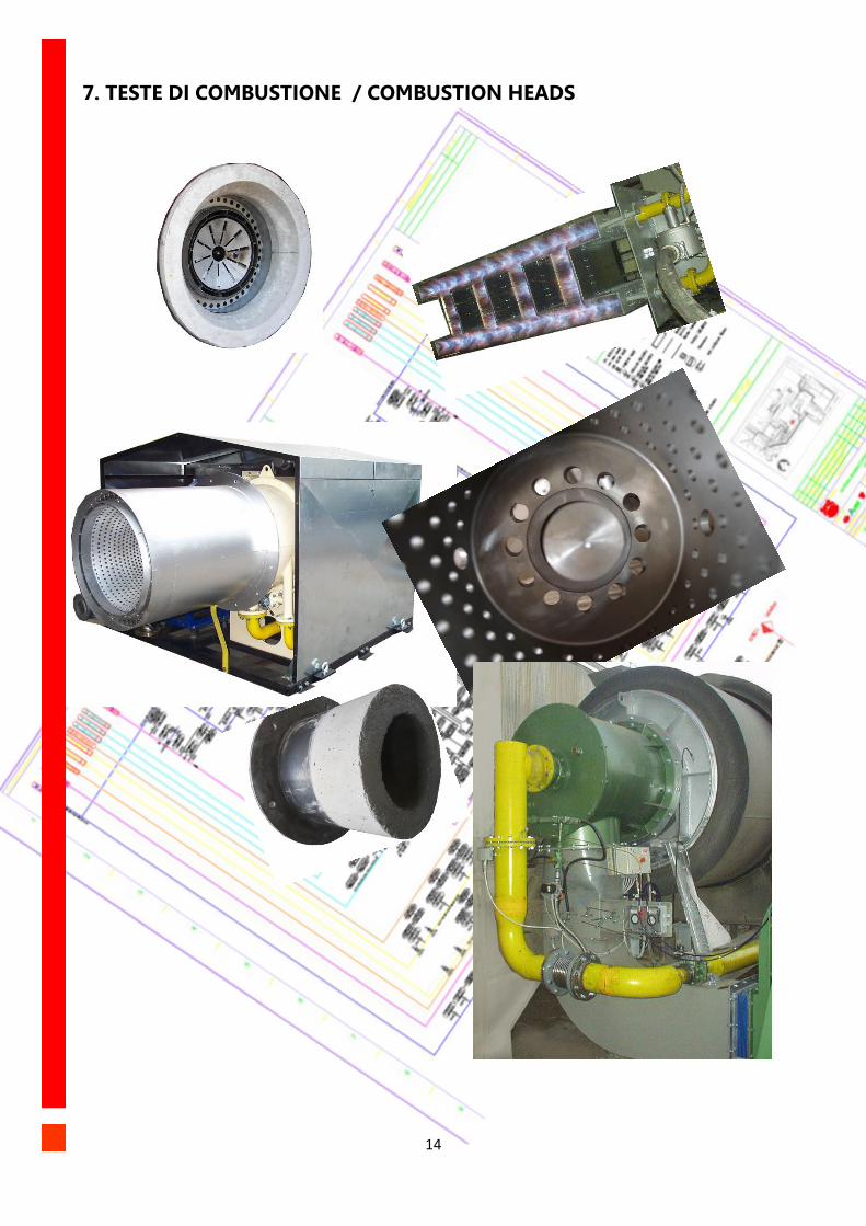
7. TESTE DI COMBUSTIONE / COMBUSTION HEADS
15
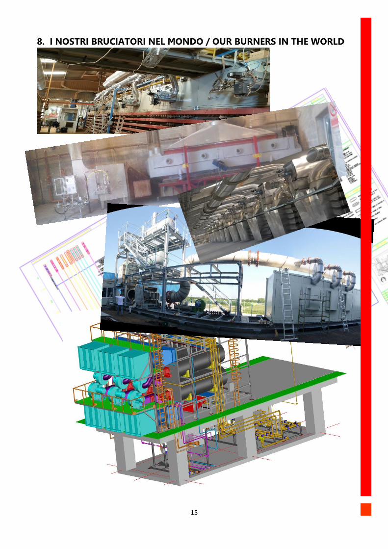
8. I NOSTRI BRUCIATORI NEL MONDO / OUR BURNERS IN THE WORLD
16
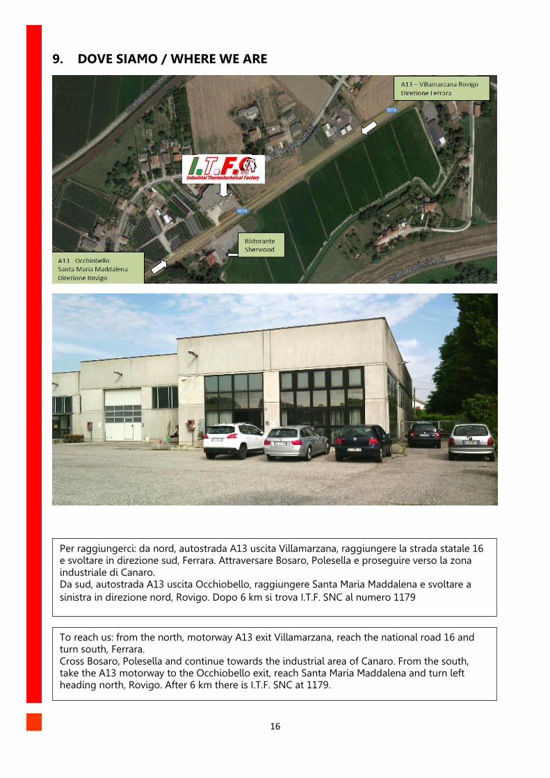
9. DOVE SIAMO / WHERE WE ARE
Per raggiungerci: da nord, autostrada A13 uscita Villamarzana, raggiungere la strada statale 16 e svoltare in direzione sud, Ferrara. Attraversare Bosaro, Polesella e proseguire verso la zona industriale di Canaro. Da sud, autostrada A13 uscita Occhiobello, raggiungere Santa Maria Maddalena e svoltare a
sinistra in direzione nord, Rovigo. Dopo 6 km si trova I.T.F. SNC al numero 1179
To reach us: from the north, motorway A13 exit Villamarzana, reach the national road 16 and turn south, Ferrara. Cross Bosaro, Polesella and continue towards the industrial area of Canaro. From the south, take the A13 motorway to the Occhiobello exit, reach Santa Maria Maddalena and turn left heading north, Rovigo. After 6 km there is I.T.F. SNC at 1179.