36
Announcement Project 2 due Fri. midnight Homework 3 out Due 2/29 Sun. Advertisement for my CS395/495 course next quarter: Computer Network Security: a Measurement-based Approach
| Date post: | 19-Dec-2015 |
| Category: |
Documents |
| View: | 214 times |
| Download: | 1 times |

Announcement
Project 2 due Fri. midnightHomework 3 out
Due 2/29 Sun.Advertisement for my CS395/495
course next quarter:Computer Network Security: a Measurement-based Approach

Dijkstra’s algorithm: example
Step012345
start NA
ADADE
ADEBADEBC
ADEBCF
D(B),p(B)2,A2,A2,A
D(C),p(C)5,A4,D3,E3,E
D(D),p(D)1,A
D(E),p(E)infinity
2,D
D(F),p(F)infinityinfinity
4,E4,E4,E
A
ED
CB
F
2
2
13
1
1
2
53
5
Some slides are in courtesy of J. Kurose and K. Ross
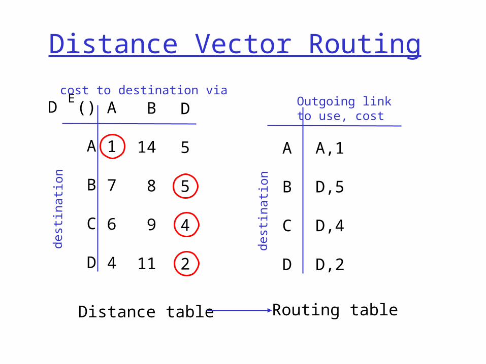
Distance Vector Routing
D ()
A
B
C
D
A
1
7
6
4
B
14
8
9
11
D
5
5
4
2
Ecost to destination via
dest
inat
ion
A
B
C
D
A,1
D,5
D,4
D,2
Outgoing link to use, cost
dest
inat
ion
Distance table Routing table
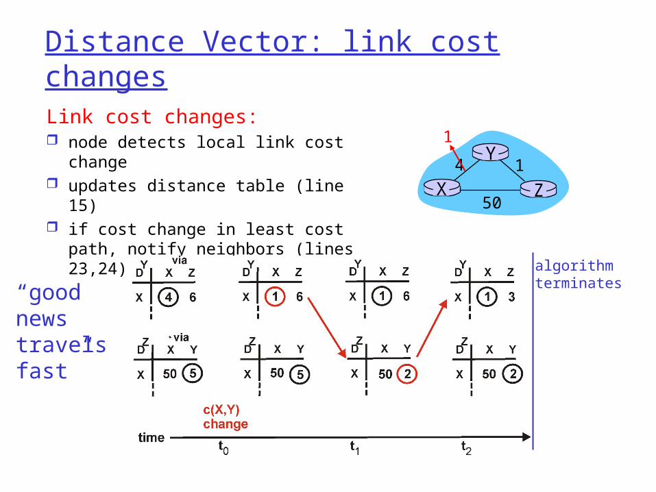
Distance Vector: link cost changes
Link cost changes: node detects local link cost
change updates distance table (line 15) if cost change in least cost path,
notify neighbors (lines 23,24)
X Z14
50
Y1
algorithmterminates“good
news travelsfast”

Distance Vector: link cost changes
Link cost changes: good news travels fast bad news travels slow -
“count to infinity” problem! X Z14
50
Y60
algorithmcontinues
on!

Distance Vector: poisoned reverse
If Z routes through Y to get to X : Z tells Y its (Z’s) distance to X is infinite (so
Y won’t route to X via Z) will this completely solve count to infinity
problem? X Z
14
50
Y60
algorithmterminates

Comparison of LS and DV algorithms
Message complexity LS: with n nodes, E links,
O(nE) msgs sent each DV: exchange between
neighbors only convergence time varies
Speed of Convergence LS: O(n2) algorithm requires
O(nE) msgs may have oscillations
DV: convergence time varies may be routing loops count-to-infinity problem
Robustness: what happens if router malfunctions?
LS: node can advertise
incorrect link cost each node computes only
its own table
DV: DV node can advertise
incorrect path cost each node’s table used by
others • error propagate thru
network

Overview Hierarchical Routing The Internet (IP) Protocol
IPv4 addressing Moving a datagram from source to
destination Datagram format IP fragmentation ICMP: Internet Control Message Protocol NAT: Network Address Translation

Hierarchical Routing
scale: with 200 million destinations:
can’t store all dest’s in routing tables!
routing table exchange would swamp links!
administrative autonomy
internet = network of networks
each network admin may want to control routing in its own network
Our routing study thus far - idealization all routers identical network “flat”… not true in practice

Hierarchical Routing
aggregate routers into regions, “autonomous systems” (AS)
routers in same AS run same routing protocol “intra-AS” routing
protocol routers in different AS
can run different intra-AS routing protocol
special routers in AS run intra-AS routing
protocol with all other routers in AS
also responsible for routing to destinations outside AS run inter-AS routing
protocol with other gateway routers
gateway routers

Intra-AS and Inter-AS routing
Gateways:•perform inter-AS routing amongst themselves•perform intra-AS routers with other routers in their AS
inter-AS, intra-AS routing in
gateway A.c
network layer
link layer
physical layer
a
b
b
aaC
A
Bd
A.a
A.c
C.bB.a
cb
c

Intra-AS and Inter-AS routing
Host h2
a
b
b
aaC
A
Bd c
A.a
A.c
C.bB.a
cb
Hosth1
Intra-AS routingwithin AS A
Inter-AS routingbetween A and B
Intra-AS routingwithin AS B
We’ll examine specific inter-AS and intra-AS Internet routing protocols shortly

Overview Hierarchical Routing The Internet (IP) Protocol
IPv4 addressing Moving a datagram from source to
destination Datagram format IP fragmentation ICMP: Internet Control Message Protocol NAT: Network Address Translation

The Internet Network layer
forwardingtable
Host, router network layer functions:
Routing protocols•path selection•RIP, OSPF, BGP
IP protocol•addressing conventions•datagram format•packet handling conventions
ICMP protocol•error reporting•router “signaling”
Transport layer: TCP, UDP
Link layer
physical layer
Networklayer

IP Addressing: introduction IP address: 32-bit
identifier for host, router interface
interface: connection between host/router and physical link router’s typically have
multiple interfaces host may have
multiple interfaces IP addresses
associated with each interface
223.1.1.1
223.1.1.2
223.1.1.3
223.1.1.4 223.1.2.9
223.1.2.2
223.1.2.1
223.1.3.2223.1.3.1
223.1.3.27
223.1.1.1 = 11011111 00000001 00000001 00000001
223 1 11

IP Addressing IP address:
network part (high order bits)
host part (low order bits)
What’s a network ? (from IP address perspective) device interfaces with
same network part of IP address
can physically reach each other without intervening router
223.1.1.1
223.1.1.2
223.1.1.3
223.1.1.4 223.1.2.9
223.1.2.2
223.1.2.1
223.1.3.2223.1.3.1
223.1.3.27
network consisting of 3 IP networks(for IP addresses starting with 223, first 24 bits are network address)
LAN

IP Addresses
0network host
10 network host
110 network host
1110 multicast address
A
B
C
D
class1.0.0.0 to127.255.255.255
128.0.0.0 to191.255.255.255
192.0.0.0 to223.255.255.255
224.0.0.0 to239.255.255.255
32 bits
given notion of “network”, let’s re-examine IP addresses:
“class-full” addressing:

IP addressing: CIDR Classful addressing:
inefficient use of address space, address space exhaustion
e.g., class B net allocated enough addresses for 65K hosts, even if only 2K hosts in that network
CIDR: Classless InterDomain Routing network portion of address of arbitrary length address format: a.b.c.d/x, where x is # bits in network
portion of address
11001000 00010111 00010000 00000000
networkpart
hostpart
200.23.16.0/23

IP addresses: how to get one?
Q: How does host get IP address?
hard-coded by system admin in a file Wintel: control-panel->network->configuration->tcp/ip-
>properties UNIX: /etc/rc.config
DHCP: Dynamic Host Configuration Protocol: dynamically get address from as server “plug-and-play”
(more shortly)

IP addresses: how to get one?
Q: How does network get network part of IP addr?
A: gets allocated portion of its provider ISP’s address space
ISP's block 11001000 00010111 00010000 00000000 200.23.16.0/20
Organization 0 11001000 00010111 00010000 00000000 200.23.16.0/23 Organization 1 11001000 00010111 00010010 00000000 200.23.18.0/23 Organization 2 11001000 00010111 00010100 00000000 200.23.20.0/23 ... ….. …. ….
Organization 7 11001000 00010111 00011110 00000000 200.23.30.0/23

Hierarchical addressing: route aggregation
“Send me anythingwith addresses beginning 200.23.16.0/20”
200.23.16.0/23
200.23.18.0/23
200.23.30.0/23
Fly-By-Night-ISP
Organization 0
Organization 7Internet
Organization 1
ISPs-R-Us“Send me anythingwith addresses beginning 199.31.0.0/16”
200.23.20.0/23Organization 2
...
...
Hierarchical addressing allows efficient advertisement of routing information:

Hierarchical addressing: more specific routes
ISPs-R-Us has a more specific route to Organization 1
“Send me anythingwith addresses beginning 200.23.16.0/20”
200.23.16.0/23
200.23.18.0/23
200.23.30.0/23
Fly-By-Night-ISP
Organization 0
Organization 7Internet
Organization 1
ISPs-R-Us“Send me anythingwith addresses beginning 199.31.0.0/16or 200.23.18.0/23”
200.23.20.0/23Organization 2
...
...

IP addressing: the last word...
Q: How does an ISP get block of addresses?
A: ICANN: Internet Corporation for Assigned
Names and Numbers allocates addresses manages DNS assigns domain names, resolves disputes

Getting a datagram from source to dest.
IP datagram:
223.1.1.1
223.1.1.2
223.1.1.3
223.1.1.4 223.1.2.9
223.1.2.2
223.1.2.1
223.1.3.2223.1.3.1
223.1.3.27
A
BE
miscfields
sourceIP addr
destIP addr data
datagram remains unchanged, as it travels source to destination
addr fields of interest here
Dest. Net. next router Nhops
223.1.1 1223.1.2 223.1.1.4 2223.1.3 223.1.1.4 2
forwarding table in A

Getting a datagram from source to dest.
Starting at A, send IP datagram addressed to B:
look up net. address of B in forwarding table
find B is on same net. as A link layer will send datagram
directly to B inside link-layer frame B and A are directly connected
Dest. Net. next router Nhops
223.1.1 1223.1.2 223.1.1.4 2223.1.3 223.1.1.4 2
miscfields223.1.1.1223.1.1.3data
223.1.1.1
223.1.1.2
223.1.1.3
223.1.1.4 223.1.2.9
223.1.2.2
223.1.2.1
223.1.3.2223.1.3.1
223.1.3.27
A
BE
forwarding table in A

Getting a datagram from source to dest.
Dest. Net. next router Nhops
223.1.1 1223.1.2 223.1.1.4 2223.1.3 223.1.1.4 2
Starting at A, dest. E: look up network address of E
in forwarding table E on different network
A, E not directly attached routing table: next hop router
to E is 223.1.1.4 link layer sends datagram to
router 223.1.1.4 inside link-layer frame
datagram arrives at 223.1.1.4 continued…..
miscfields223.1.1.1223.1.2.3 data
223.1.1.1
223.1.1.2
223.1.1.3
223.1.1.4 223.1.2.9
223.1.2.2
223.1.2.1
223.1.3.2223.1.3.1
223.1.3.27
A
BE
forwarding table in A

Getting a datagram from source to dest.
Arriving at 223.1.4, destined for 223.1.2.2
look up network address of E in router’s forwarding table
E on same network as router’s interface 223.1.2.9 router, E directly attached
link layer sends datagram to 223.1.2.2 inside link-layer frame via interface 223.1.2.9
datagram arrives at 223.1.2.2!!! (hooray!)
miscfields223.1.1.1223.1.2.3 data Dest. Net router Nhops interface
223.1.1 - 1 223.1.1.4 223.1.2 - 1 223.1.2.9
223.1.3 - 1 223.1.3.27
223.1.1.1
223.1.1.2
223.1.1.3
223.1.1.4 223.1.2.9
223.1.2.2
223.1.2.1
223.1.3.2223.1.3.1
223.1.3.27
A
BE
forwarding table in router

IP datagram format
ver length
32 bits
data (variable length,typically a TCP
or UDP segment)
16-bit identifier
Internet checksum
time tolive
32 bit source IP address
IP protocol versionnumber
header length (bytes)
max numberremaining hops
(decremented at each router)
forfragmentation/reassembly
total datagramlength (bytes)
upper layer protocolto deliver payload to
head.len
type ofservice
“type” of data flgsfragment
offsetupper layer
32 bit destination IP address
Options (if any) E.g. timestamp,record routetaken, specifylist of routers to visit.
how much overhead with TCP?
20 bytes of TCP 20 bytes of IP = 40 bytes + app
layer overhead

IP Fragmentation & Reassembly network links have MTU
(max.transfer size) - largest possible link-level frame. different link types,
different MTUs large IP datagram divided
(“fragmented”) within net one datagram becomes
several datagrams “reassembled” only at
final destination IP header bits used to
identify, order related fragments
fragmentation: in: one large datagramout: 3 smaller datagrams
reassembly

IP Fragmentation and Reassembly
ID=x
offset=0
fragflag=0
length=4000
ID=x
offset=0
fragflag=1
length=1500
ID=x
offset=1480
fragflag=1
length=1500
ID=x
offset=2960
fragflag=0
length=1040
One large datagram becomesseveral smaller datagrams
Example 4000 byte
datagram MTU = 1500 bytes

ICMP: Internet Control Message Protocol
used by hosts, routers, gateways to communication network-level information error reporting: unreachable host, network, port,
protocol echo request/reply (used by ping)
network-layer “above” IP: ICMP msgs carried in IP datagrams
Ping, traceroute uses ICMP

NAT: Network Address Translation
10.0.0.1
10.0.0.2
10.0.0.3
10.0.0.4
138.76.29.7
local network(e.g., home network)
10.0.0/24
rest ofInternet
Datagrams with source or destination in this networkhave 10.0.0/24 address for
source, destination (as usual)
All datagrams leaving localnetwork have same single source
NAT IP address: 138.76.29.7,different source port numbers

NAT: Network Address Translation
Motivation: local network uses just one IP address as far as outside word is concerned: no need to be allocated range of addresses from
ISP: - just one IP address is used for all devices can change addresses of devices in local network
without notifying outside world can change ISP without changing addresses of
devices in local network devices inside local net not explicitly
addressable, visible by outside world (a security plus).

NAT: Network Address Translation
Implementation: NAT router must:
outgoing datagrams: replace (source IP address, port #) of every outgoing datagram to (NAT IP address, new port #). . . remote clients/servers will respond using (NAT IP
address, new port #) as destination addr.
remember (in NAT translation table) every (source IP address, port #) to (NAT IP address, new port #) translation pair
incoming datagrams: replace (NAT IP address, new port #) in dest fields of every incoming datagram with corresponding (source IP address, port #) stored in NAT table

NAT: Network Address Translation
10.0.0.1
10.0.0.2
10.0.0.3
S: 10.0.0.1, 3345D: 128.119.40.186, 80
1
10.0.0.4
138.76.29.7
1: host 10.0.0.1 sends datagram to 128.119.40, 80
NAT translation tableWAN side addr LAN side addr
138.76.29.7, 5001 10.0.0.1, 3345…… ……
S: 128.119.40.186, 80 D: 10.0.0.1, 3345
4
S: 138.76.29.7, 5001D: 128.119.40.186, 80
2
2: NAT routerchanges datagramsource addr from10.0.0.1, 3345 to138.76.29.7, 5001,updates table
S: 128.119.40.186, 80 D: 138.76.29.7, 5001
3
3: Reply arrives dest. address: 138.76.29.7, 5001
4: NAT routerchanges datagramdest addr from138.76.29.7, 5001 to 10.0.0.1, 3345

NAT: Network Address Translation
16-bit port-number field: 60,000 simultaneous connections with a
single LAN-side address! NAT is controversial:
routers should only process up to layer 3 violates end-to-end argument
• NAT possibility must be taken into account by app designers, eg, P2P applications
address shortage should instead be solved by IPv6


