ANNULAR-RING COUPLED STRUCTURE LINAC FOR THE J-PARC LINAC ENERGY UPGRADE H. Ao ∗ , H. Asano, J. Tamura, Y. Nemoto, N. Ouchi, J-PARC, JAEA, Ibaraki, Japan F. Naito, K. Takata, J-PARC, KEK, Ibaraki, Japan Abstract The Japan Proton Accelerator Research Complex (J- PARC) linac is the injector to the 3-GeV rapid cycle syn- chrotron. To increase the beam power of the synchrotron, the task of upgrading the energy of the linac to 400 MeV started in March 2009. At the downstream of the 191-MeV separated-type drift tube linac, 25 modules of the annular- ring coupled structure (ACS) linac will be added in August 2013. Cavity fabrication of the ACS is nearly complete, and the completed modules are kept at the J-PARC site. Currently, pumps and vacuum components are being in- stalled on the cavities for testing of vacuum conditions. For the J-PARC pulsed beam, vacuum pressures need to be less than 10 −5 Pa along the beam line in order not to exceed 0.1 W/m beam loss. In this paper, we present the measurement results for reducing the vacuum pressure using the stored ACS cavity to enable the high-intensity operation. INTRODUCTION The annular-ring coupled structure (ACS) linac will be added to the Japan Proton Accelerator Research Complex (J-PARC) in August to increase the linac beam energy from 181 to 400 MeV. A total of 25 ACS modules have been fabricated, and two buncher modules and two accelerating modules have already been conditioned up to the design input power [1]. Keeping vacuum pressures as low as possible (typically, less than 10 −6 Pa) is important for reducing the beam loss from residual gas in high-intensity proton accelera- tors. During user operation, research and development on vacuum improvement can be difficult because it would re- quire the frequent changing of vacuum pumps and vacuum gauges. The vacuum pressure distribution in the ACS mod- ule was, therefore, measured and attempts were made to improve it using the stored module before installation. This report describes the evacuation test and the possible vac- uum improvement options that will enable high-intensity operation. EVACUATION TEST As additional vacuum pumps, nonevaporable getter (NEG) pumps (CapaciTorr D400 manufactured by SAES Getters [2]) were used in this experiment to improve the vacuum pressure. NEG pumps have several advantages; they are its lightweight, can be easily attached to the cavity, and do not need an additional high-voltage cable. Mean- while, the lifetime (interval of activation) should be con- ∗ [email protected]firmed separately because its pumping process sorbs active gas molecules by chemical reaction. Figure 1 shows the configuration of the NEG pumps and the vacuum gauges (Bayard-Alpert). One ACS accelerating module is evacuated by two 500 L/s ion pumps (IPs), one at each end, and one 150 L/s IP at the center. When the achieved vacuum pressure was around 10 −6 Pa after the 60 h of evacuation, the change in vacuum pressure caused by additional NEG pumps (resulting from the opening or closing of the angle valve attached to the NEG pump) was measured. Bridge tank 1 2 2 2 2 3 5 5 5 5 5 5 5 5 5 5 5 5 5 5 5 5 5 5 9 9 9 9 9 9 9 9 9 9 9 9 9 9 9 9 9 9 12 12 2 1 1 1 1 1 2 2 2 2 2 2 2 2 2 2 2 2 15 5 5 5 5 5 5 5 1 1 1 1 1 1 54 5 5 5 5 5 5 55 56 57 58 59 5 9 59 18 1 1 1 1 1 1 1 1 8 1 1 1 18 8 8 8 8 8 21 1 1 21 1 1 1 2 2 2 2 2 2 2 2 24 24 4 2 2 2 2 2 24 4 4 4 4 4 4 4 4 4 4 4 27 2 2 27 2 27 27 27 7 7 7 2 2 2 2 2 2 2 2 2 2 30 3 0 3 3 3 3 3 3 3 30 0 0 3 3 30 30 0 0 0 0 33 3 3 3 3 3 3 3 3 3 33 3 3 3 3 3 3 3 3 3 36 36 6 3 3 3 3 3 3 6 6 6 6 6 6 6 6 6 6 6 39 9 9 9 3 39 39 9 9 9 9 3 3 3 3 3 3 3 3 3 3 42 2 2 2 4 42 42 2 2 2 2 4 4 4 4 4 4 4 4 4 4 4 45 5 5 5 4 45 45 5 5 5 5 4 4 4 4 4 4 4 4 4 4 48 8 8 8 8 8 48 8 8 8 8 4 8 4 8 4 4 4 4 4 4 8 51 5 5 5 5 5 5 5 5 5 5 51 51 51 1 1 51 5 5 60 Vaccum gauge 1 3 (NEG) 5 2 4 (NEG) 500 L/s Ion pump 150 L/s Ion pump 500 L/s Ion pump 150 L/s Ion pump Beam axis Vacuum manifold NEG NEG NEG NEG (Configuration #2) (Configuration #1) Coupling cell Accelerating cell Accelerating tank Figure 1: Configuration of NEG pumps (#1 and #2) and vacuum gauges (1-5) and diagram of the vacuum network in the ACS accelerating tank (nodes 1-60). The following two NEG pump configurations were com- pared: • (#1) NEG pumps were attached to the center of the accelerating tank (node 33). This point is far from the IPs and is expected to have the highest pressure. • (#2) NEG pumps were attached to the vacuum mani- folds at both ends of the module. Here, it should be mentioned that the rotating tuner at- tached to the coupling cell needs to be removed when the additional NEG pump is added at the center of the acceler- ating tank. The measured pressures for the configuration #1 are shown in Fig. 2 and listed in Table 1. It can be seen from Proceedings of IPAC2013, Shanghai, China THPWO036 04 Hadron Accelerators A08 Linear Accelerators ISBN 978-3-95450-122-9 3845 Copyright c ○ 2013 by JACoW — cc Creative Commons Attribution 3.0 (CC-BY-3.0)
Transcript
ANNULAR-RING COUPLED STRUCTURE LINAC FOR THE J-PARCLINAC ENERGY UPGRADE
H. Ao∗, H. Asano, J. Tamura, Y. Nemoto, N. Ouchi, J-PARC, JAEA, Ibaraki, JapanF. Naito, K. Takata, J-PARC, KEK, Ibaraki, Japan
AbstractThe Japan Proton Accelerator Research Complex (J-
PARC) linac is the injector to the 3-GeV rapid cycle syn-chrotron. To increase the beam power of the synchrotron,the task of upgrading the energy of the linac to 400 MeVstarted in March 2009. At the downstream of the 191-MeVseparated-type drift tube linac, 25 modules of the annular-ring coupled structure (ACS) linac will be added in August2013. Cavity fabrication of the ACS is nearly complete,and the completed modules are kept at the J-PARC site.Currently, pumps and vacuum components are being in-stalled on the cavities for testing of vacuum conditions. Forthe J-PARC pulsed beam, vacuum pressures need to be lessthan 10−5 Pa along the beam line in order not to exceed 0.1W/m beam loss. In this paper, we present the measurementresults for reducing the vacuum pressure using the storedACS cavity to enable the high-intensity operation.
INTRODUCTIONThe annular-ring coupled structure (ACS) linac will be
added to the Japan Proton Accelerator Research Complex(J-PARC) in August to increase the linac beam energy from181 to 400 MeV. A total of 25 ACS modules have beenfabricated, and two buncher modules and two acceleratingmodules have already been conditioned up to the designinput power [1].Keeping vacuum pressures as low as possible (typically,
less than 10−6 Pa) is important for reducing the beamloss from residual gas in high-intensity proton accelera-tors. During user operation, research and development onvacuum improvement can be difficult because it would re-quire the frequent changing of vacuum pumps and vacuumgauges. The vacuum pressure distribution in the ACS mod-ule was, therefore, measured and attempts were made toimprove it using the stored module before installation. Thisreport describes the evacuation test and the possible vac-uum improvement options that will enable high-intensityoperation.
(NEG) pumps (CapaciTorr D400 manufactured by SAESGetters [2]) were used in this experiment to improve thevacuum pressure. NEG pumps have several advantages;they are its lightweight, can be easily attached to the cavity,and do not need an additional high-voltage cable. Mean-while, the lifetime (interval of activation) should be con-
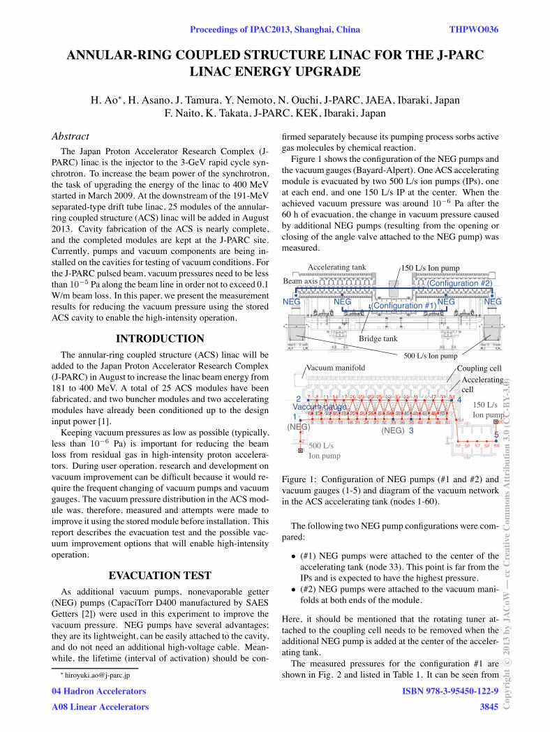
firmed separately because its pumping process sorbs activegas molecules by chemical reaction.Figure 1 shows the configuration of the NEG pumps and
the vacuumgauges (Bayard-Alpert). One ACS acceleratingmodule is evacuated by two 500 L/s ion pumps (IPs), oneat each end, and one 150 L/s IP at the center. When theachieved vacuum pressure was around 10−6 Pa after the60 h of evacuation, the change in vacuum pressure causedby additional NEG pumps (resulting from the opening orclosing of the angle valve attached to the NEG pump) wasmeasured.
Figure 1: Configuration of NEG pumps (#1 and #2) andvacuum gauges (1-5) and diagram of the vacuum networkin the ACS accelerating tank (nodes 1-60).
The following two NEG pump configurations were com-pared:
• (#1) NEG pumps were attached to the center of theaccelerating tank (node 33). This point is far from theIPs and is expected to have the highest pressure.
• (#2) NEG pumps were attached to the vacuum mani-folds at both ends of the module.
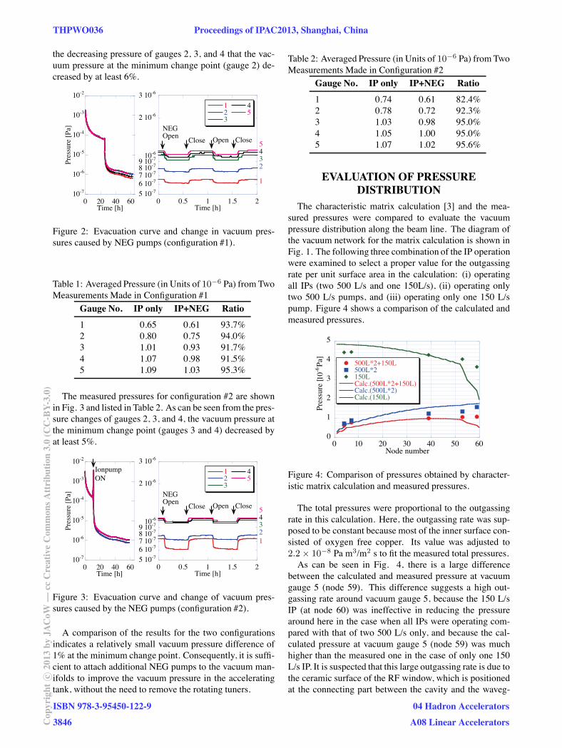
Here, it should be mentioned that the rotating tuner at-tached to the coupling cell needs to be removed when theadditional NEG pump is added at the center of the acceler-ating tank.The measured pressures for the configuration #1 are
shown in Fig. 2 and listed in Table 1. It can be seen from
Proceedings of IPAC2013, Shanghai, China THPWO036
04 Hadron Accelerators
A08 Linear Accelerators
ISBN 978-3-95450-122-9
3845 Cop
yrig
htc ○
2013
byJA
CoW
—cc
Cre
ativ
eC
omm
onsA
ttri
butio
n3.
0(C
C-B
Y-3.
0)
the decreasing pressure of gauges 2, 3, and 4 that the vac-uum pressure at the minimum change point (gauge 2) de-creased by at least 6%.
5 10-76 10-77 10-78 10-79 10-710-6
2 10-6
3 10-6
0 0.5 1 1.5 2
123
45
Time [h]
NEGOpen
Close CloseOpen5432
1
10-7
10-6
10-5
10-4
10-3
10-2
0 20 40 60
Pres
sure
[Pa
]
Time [h]
Figure 2: Evacuation curve and change in vacuum pres-sures caused by NEG pumps (configuration #1).
Table 1: Averaged Pressure (in Units of 10−6 Pa) from TwoMeasurements Made in Configuration #1
The measured pressures for configuration #2 are shownin Fig. 3 and listed in Table 2. As can be seen from the pres-sure changes of gauges 2, 3, and 4, the vacuum pressure atthe minimum change point (gauges 3 and 4) decreased byat least 5%.
5 10-76 10-77 10-78 10-79 10-710-6
2 10-6
3 10-6
0 0.5 1 1.5 2
123
45
Time [h]
NEGOpen
Close CloseOpen54321
10-7
10-6
10-5
10-4
10-3
10-2
0 20 40 60
Pres
sure
[Pa
]
Time [h]
IonpumpON
Figure 3: Evacuation curve and change of vacuum pres-sures caused by the NEG pumps (configuration #2).
A comparison of the results for the two configurationsindicates a relatively small vacuum pressure difference of1% at the minimum change point. Consequently, it is suffi-cient to attach additional NEG pumps to the vacuum man-ifolds to improve the vacuum pressure in the acceleratingtank, without the need to remove the rotating tuners.
Table 2: Averaged Pressure (in Units of 10−6 Pa) from TwoMeasurements Made in Configuration #2
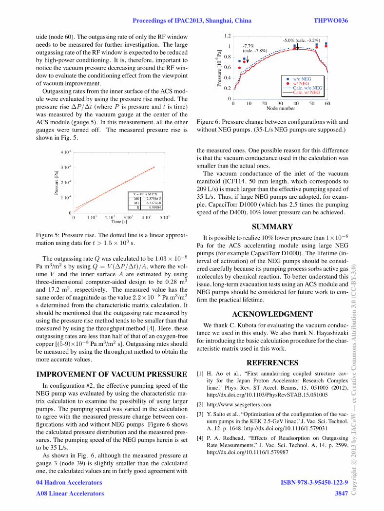
The characteristic matrix calculation [3] and the mea-sured pressures were compared to evaluate the vacuumpressure distribution along the beam line. The diagram ofthe vacuum network for the matrix calculation is shown inFig. 1. The following three combination of the IP operationwere examined to select a proper value for the outgassingrate per unit surface area in the calculation: (i) operatingall IPs (two 500 L/s and one 150L/s), (ii) operating onlytwo 500 L/s pumps, and (iii) operating only one 150 L/spump. Figure 4 shows a comparison of the calculated andmeasured pressures.
Figure 4: Comparison of pressures obtained by character-istic matrix calculation and measured pressures.
The total pressures were proportional to the outgassingrate in this calculation. Here, the outgassing rate was sup-posed to be constant because most of the inner surface con-sisted of oxygen free copper. Its value was adjusted to2.2 × 10−8 Pa m3/m2 s to fit the measured total pressures.As can be seen in Fig. 4, there is a large difference
between the calculated and measured pressure at vacuumgauge 5 (node 59). This difference suggests a high out-gassing rate around vacuum gauge 5, because the 150 L/sIP (at node 60) was ineffective in reducing the pressurearound here in the case when all IPs were operating com-pared with that of two 500 L/s only, and because the cal-culated pressure at vacuum gauge 5 (node 59) was muchhigher than the measured one in the case of only one 150L/s IP. It is suspected that this large outgassing rate is due tothe ceramic surface of the RF window, which is positionedat the connecting part between the cavity and the waveg-
THPWO036 Proceedings of IPAC2013, Shanghai, China
ISBN 978-3-95450-122-9
3846Cop
yrig
htc ○
2013
byJA
CoW
—cc
Cre
ativ
eC
omm
onsA
ttri
butio
n3.
0(C
C-B
Y-3.
0)
04 Hadron Accelerators
A08 Linear Accelerators
uide (node 60). The outgassing rate of only the RF windowneeds to be measured for further investigation. The largeoutgassing rate of the RF window is expected to be reducedby high-power conditioning. It is, therefore, important tonotice the vacuum pressure decreasing around the RF win-dow to evaluate the conditioning effect from the viewpointof vacuum improvement.Outgassing rates from the inner surface of the ACS mod-
ule were evaluated by using the pressure rise method. Thepressure rise ΔP/Δt (where P is pressure and t is time)was measured by the vacuum gauge at the center of theACS module (gauge 5). In this measurement, all the othergauges were turned off. The measured pressure rise isshown in Fig. 5.
0
1 10-4
2 10-4
3 10-4
4 10-4
0 1 103 2 103 3 103 4 103 5 103
Pres
sure
[Pa
]
Time [s]
Y = M0 + M1*X2.5754e-5M06.3377e-8M1
0.99984R
Figure 5: Pressure rise. The dotted line is a linear approxi-mation using data for t > 1.5 × 10³ s.
The outgassing rate Q was calculated to be 1.03× 10⁻⁸
Pa m3/m2 s by using Q = V (ΔP/Δt)/A, where the vol-ume V and the inner surface A are estimated by usingthree-dimensional computer-aided design to be 0.28 m3
and 17.2 m2, respectively. The measured value has thesame order of magnitude as the value 2.2×10⁻⁸ Pa m3/m2
s determined from the characteristic matrix calculation. Itshould be mentioned that the outgassing rate measured byusing the pressure rise method tends to be smaller than thatmeasured by using the throughput method [4]. Here, theseoutgassing rates are less than half of that of an oxygen-freecopper [(5-9)×10−8 Pa m3/m2 s]. Outgassing rates shouldbe measured by using the throughput method to obtain themore accurate values.
IMPROVEMENT OF VACUUM PRESSUREIn configuration #2, the effective pumping speed of the
NEG pump was evaluated by using the characteristic ma-trix calculation to examine the possibility of using largerpumps. The pumping speed was varied in the calculationto agree with the measured pressure change between con-figurations with and without NEG pumps. Figure 6 showsthe calculated pressure distribution and the measured pres-sures. The pumping speed of the NEG pumps herein is setto be 35 L/s.As shown in Fig. 6, although the measured pressure at
gauge 3 (node 39) is slightly smaller than the calculatedone, the calculated values are in fairly good agreement with
0
0.2
0.4
0.6
0.8
1
1.2
0 10 20 30 40 50 60
w/o NEGw/ NEGCalc. w/o NEGCalc. w/ NEG
Pres
sure
[10
-6 Pa
]
Node number
-7.7%(calc. -7.8%)
-5.0% (calc. -3.2%)
Figure 6: Pressure change between configurations with andwithout NEG pumps. (35-L/s NEG pumps are supposed.)
the measured ones. One possible reason for this differenceis that the vacuum conductance used in the calculation wassmaller than the actual ones.The vacuum conductance of the inlet of the vacuum
manifold (ICF114, 50 mm length, which corresponds to209 L/s) is much larger than the effective pumping speed of35 L/s. Thus, if large NEG pumps are adopted, for exam-ple, CapaciTorr D1000 (which has 2.5 times the pumpingspeed of the D400), 10% lower pressure can be achieved.
SUMMARYIt is possible to realize 10% lower pressure than 1×10⁻⁶
Pa for the ACS accelerating module using large NEGpumps (for example CapaciTorr D1000). The lifetime (in-terval of activation) of the NEG pumps should be consid-ered carefully because its pumping process sorbs active gasmolecules by chemical reaction. To better understand thisissue, long-term evacuation tests using an ACS module andNEG pumps should be considered for future work to con-firm the practical lifetime.
ACKNOWLEDGMENTWe thank C. Kubota for evaluating the vacuum conduc-
tance we used in this study. We also thank N. Hayashizakifor introducing the basic calculation procedure for the char-acteristic matrix used in this work.
REFERENCES[1] H. Ao et al., “First annular-ring coupled structure cav-
ity for the Japan Proton Accelerator Research Complexlinac,” Phys. Rev. ST Accel. Beams, 15, 051005 (2012),http://dx.doi.org/10.1103/PhysRevSTAB.15.051005
[2] http://www.saesgetters.com
[3] Y. Saito et al., “Optimization of the configuration of the vac-uum pumps in the KEK 2.5-GeV linac,” J. Vac. Sci. Technol.A, 12, p. 1648, http://dx.doi.org/10.1116/1.579031
[4] P. A. Redhead, “Effects of Readsorption on OutgassingRate Measurements,” J. Vac. Sci. Technol. A, 14, p. 2599,http://dx.doi.org/10.1116/1.579987