ANSI Meter DM-06 Functional Specification Requirements Rev. B USCL Confidential Page 1 of 83 , ANSI METER DM-06 FUNCTIONAL SPECIFICATION REQUIREMENTS EnergyCite™ October 31, 2006 Final Release
Transcript
ANSI Meter DM-06 Functional Specification Requirements Rev. B
USCL Confidential Page 1 of 83
,
ANSI METER DM-06
FUNCTIONAL SPECIFICATION REQUIREMENTS
EnergyCite™
October 31, 2006 Final Release
ANSI Meter DM-06 Functional Specification Requirements Rev. B
USCL Confidential Page 2 of 83
Document Control Sheet
Change Record
Date Author Version Change Reference
March 13, 2003 Victor Kolesnichenko 0.1
May 20, 2006 Victor Kolesnichenko 0.2
May 30, 2006 Victor Kolesnichenko 0.3
June 12, 2006 Victor Kolesnichenko 0.4
July 3, 2006 Victor Kolesnichenko A Released
October 31, 2006 Victor Kolesnichenko B Added Reactive Measurements
Reviewers
Name Position
Tom Tamarkin USCL CEO 2006
Distribution
Name Position
Control
Composed by: Victor Kolesnichenko Date: Released October 31, 2006
Validated by: Date:
Approved by: Date: November 2, 2006
ANSI Meter DM-06 Functional Specification Requirements Rev. B
USCL Confidential Page 3 of 83
CONTENTS
0. GLOSSARY OF TERMS .................................................................... 8
1. General Information .......................................................................... 12
3.2 INPUT REQUIREMENTS ............................................................................................. 19 3.2.1 Operating Voltage Range ............................................................................................ 19 3.2.2 Operating Frequency Range ....................................................................................... 19
3.2.3 Operating Current Range ........................................................................................... 19 3.3 OUTPUT REQUIREMENTS ......................................................................................... 19
3.3.1 IR calibration LED (test output) ................................................................................ 19 3.3.2 Display Requirements .................................................................................................. 20
3.5 DISCONNECT RELAY .................................................................................................. 23 3.5.1 Voltage Sensing on the Load Side .............................................................................. 23 3.5.2 Status of Disconnect Relay .......................................................................................... 23
3.5.3 Disconnect Relay as a Current Limiting means ........................................................ 23 3.6 INTERFACING REQUIREMENTS ............................................................................. 24
3.6.1 Wide Area Network Data Telecommunications........................................................ 24 3.6.2 Optical Port .................................................................................................................. 24
3.6.3 Data Structures ........................................................................................................ 24 3.7 SYSTEM ACCURACY REQUIREMENTS ................................................................. 25
3.7.1 No Load ......................................................................................................................... 25
3.7.2 Starting Load ................................................................................................................ 25 3.7.3 Load Variation ............................................................................................................. 25 3.7.4 Power Factor Variation ............................................................................................... 26 3.7.5 Power Factor Monitoring and Reporting .................................................................. 26 3.7.6 Voltage Variation ......................................................................................................... 27
3.7.7 Over Voltage and Under Voltage Reporting ............................................................. 27 3.7.8 Voltage sag/swell event log (magnitude and duration) ............................................. 27 3.7.9 Voltage profile .............................................................................................................. 28 3.7.10 Frequency Variation ................................................................................................ 29
3.7.11 Load Current Imbalances ....................................................................................... 29 3.7.10 Internal Heating ....................................................................................................... 30 3.7.11 Stability Over Time.................................................................................................. 30 3.7.12 Voltage Interruption ................................................................................................ 31 3.7.13 External Magnetic Field .......................................................................................... 31
ANSI Meter DM-06 Functional Specification Requirements Rev. B
USCL Confidential Page 4 of 83
3.7.14 Temperature Coefficient ......................................................................................... 32 3.7.15 DC load current........................................................................................................ 32 3.7.16 Temporary Overload ............................................................................................... 33
3.8 POWER CONSUMPTION REQUIREMENTS ........................................................... 34
3.8.1 Current Circuit Loss.................................................................................................... 34 3.8.2 Voltage Circuit Loss .................................................................................................... 34
3.9 FUNCTIONAL FEATURES .......................................................................................... 34 3.9.1 Registered Quantities................................................................................................... 34 3.9.2 Maximum Demand Register ....................................................................................... 35
3.9.3 Time-of-Use Function (TOU) ...................................................................................... 35 3.9.4 Load Profile .................................................................................................................. 36 3.9.5 Prepayment Meter Mode ............................................................................................ 37 3.9.6 Consumption Meter Support ...................................................................................... 38
3.9.7 Dynamic or Real Time Pricing. .................................................................................. 39 3.9.8 Subscriber Side Billing ................................................................................................ 39
3.9.9 Tamper Detection......................................................................................................... 39 3.10 OTHER FUNCTIONAL SYSTEM REQUIREMENTS .............................................. 41
3.12.1 Fault Current ........................................................................................................... 49 3.12.2 High-Voltage Line Surges ....................................................................................... 49 3.12.3 Current Surge in Ground Conductor .................................................................... 49
3.12.4 High Voltage Line Surge ......................................................................................... 49 3.12.5 Superimposed Signals .............................................................................................. 50
3.13.5 Spring Hammer Test .................................................................................................. 56 3.13.6 Raintightness ............................................................................................................... 56
7.1. Meter certification Cost .......................................................................................................... 68
8. Compliance Test Sequence .................................................................. 69
Table 2. List of Tests in ANSI C12.1 and C12.20 Standards .................................................... 70 8.1 Tests of accuracy requirements ................................................................................................ 71
8.1.4 Power Factor Variation .................................................................................................. 72 8.1.5 Effect of Voltage Variation ............................................................................................ 72
8.1.6 Effect of Frequency Variation ....................................................................................... 73 8.1.7 Equality of Current Cicuits ............................................................................................ 73 8.1.8 Effect of Internal Heating .............................................................................................. 74
8.1.9 Stability Over Time........................................................................................................ 74
8.1.10 Effect of External Magnetic Field.............................................................................. 75 8.1.11 Effect of Ambient Temperature ................................................................................. 75 8.1.12 Temporary Overload .................................................................................................. 76
8.1.13 DC load current .......................................................................................................... 76 8.2 External Influences ................................................................................................................. 77
8.2.1 Insulation........................................................................................................................... 77 8.2.2 Voltage Interruption .......................................................................................................... 77
8.2.3 High Voltage Line Surges ................................................................................................. 77 8.2.4 Effect on Mechanical Structure and Insulation ................................................................ 77 8.2.5 Effect of Voltage Variation – Secondary Time Base....................................................... 77 8.2.5 Effect of Ambient Temperature Variation – Secondary Time Base ................................ 77 8.2.6 Electrical Fast Transient/Burst Test ................................................................................. 78
8.2.7 Effect of Radio Frequency Interference ........................................................................... 78 8.2.8 Conducted and Radiated Emissions ............................................................................... 78
8.2.9 Effect of Electrostatic Discharge (ESD) .......................................................................... 78 8.2.10 Effect of Storage Temperature ....................................................................................... 78 8.2.11 Effect of Operating Temperature ................................................................................... 78 8.2.12 Effect of Relative Humidity ........................................................................................... 78 8.2.13 Mechanical Shock .......................................................................................................... 79 8.2.14 Transportation Vibration ................................................................................................ 79
ANSI Meter DM-06 Functional Specification Requirements Rev. B
USCL Confidential Page 7 of 83
8.2.15 Transportation Drop ....................................................................................................... 79 8.2.16 Mechanical Vibration..................................................................................................... 79 8.2.17 Weather Simulation Test................................................................................................ 79 8.2.18 Salt-Spay Test ................................................................................................................ 80
8.2.19 Raintightness .................................................................................................................. 80 8.3 Meter Losses ........................................................................................................................... 80 8.4 Temperature Rise .................................................................................................................... 80
9 Other Tests .......................................................................................... 81
9.1 Voltage Measurements....................................................................................................... 81 9.2 Current Measurements ....................................................................................................... 81 9.2 Reactive Power/Energy Measurements ............................................................................. 81 9.3 Power Factor Calculation ........................................................................................................ 81 9.3 Frequency Measurements .................................................................................................. 82
9.4.2 Outdoor Sunlight Test .................................................................................................... 82
ANSI Meter DM-06 Functional Specification Requirements Rev. B
USCL Confidential Page 8 of 83
0. GLOSSARY OF TERMS
Accuracy - The extend to which a given measurement agrees with the defined value.
Accuracy Class - The maximum allowable error of measurement at reference conditions. Active Power - The power that performs the actual work of creating heat, light, motion, and so on. Active power is measured in kiloWatts (kW). It works in conjunction with reactive power, to form apparent power. For sine-wave voltage and current, the active power can be calculated as following: Active Power = RMS voltage x RMS current x power factor (PF). See also “Reactive Power”, “Apparent Power”, and “Power Factor”. Apparent Power - The product of RMS voltage and RMS current. Apparent Power is a square root of the sum of squares of Active Power and Reactive Power. AMR - Acronym for Automated Meter Reading. Reading of meters from a remote location. ANSI - Acronym for the American National Standards Institute, which is a nonprofit, privately funded membership organization that coordinates the development of U.S. voluntary national standards and represents the U.S. in international standards organizations. The institute promotes and facilitates the development and integrity of voluntary consensus standards and conformity assessment systems. Current Transformer (CT) - A transformer in electrical devices for measuring current. Primary winding carries the load current, and secondary winding is loaded with a burden resistor. CTs use the strength of the magnetic field around the conductor to form an induced current. The induced secondary current is proportional to the primary current in a wide range of amplitudes and frequencies. Demand - The average value of power or other parameter over specified interval of time (see below). Demand Interval - A programmable interval of averaging of power or other parameter. Usual values are 1, 5, 10, 15, 30, 60 minutes. Demand, Maximum- Peak Demand. The highest demand measured over a selected period of time, such as one month. Demand Metering - The process of computing and storing the demand and/or maximum demand, as calculated with a precisely defined methodology. This methodology is based on historical observation of the measured energy delivery.
ANSI Meter DM-06 Functional Specification Requirements Rev. B
USCL Confidential Page 9 of 83
Demand Response- Reducing demand in response to a curtailment notification or short term price signal. Electricity Meter - A device that measures and records electrical parameters (such as energy) over a period of time. End of Interval (EOI)- Signals the end of a demand interval. Energy - The integral of power over time. Firmware - Software that is embedded in the electronic device. Hertz - Cycles per Second. The practical unit of frequency measurement. IEC - Acronym for the International Electrotechnical Commission, which is a world organization that prepares and publishes international standards for all electrical, electronic, and related technologies. The members are national committees for each country, whose representatives are from all sectors of the electrical industry and deal with questions of standardization at the international level. Instrument Transformer A transformer that reproduces in its secondary circuit, in a definite and known proportion, the voltage or currentof its primary circuit, with the phase relation substantially preserved. kVA - Kilovolt amperes of apparent power (RMS Volts times RMS Amperes multiplied by 1,000); 1kVA=1,000 VA. kVAh - Kilovolt Amperes of apparent power hours. See kVA. kVAr - KiloVolt Amperes of reactive power (Volts times Amperes of reactive power multiplied by 1,000); 1kVAr=1,000 VAr. kVArh - KiloVolt Amperes of reactive power hours. See kVAr. kW - A kiloWatt equals 1,000 Watts; 1 kW=1,000 W. kWh - KiloWatt hour (kW times hours). A kiloWatt is a unit of electrical power equal to 1,000 Watts. A kiloWatt hour is a unit of electrical energy equal to one kiloWatt used for one hour.
KYZ Output - A three-wire pulse output from a metering device to drive external control or recording equipment. Each pulse represents a predetermined value of a certain parameter.
ANSI Meter DM-06 Functional Specification Requirements Rev. B
USCL Confidential Page 10 of 83
LAN - Local Area Network. A network consisting of nodes that are confined within a localized area. For example, a floor of a building, or the building itself. (See Wide-Area Network) Lagging Current - The current flowing in a circuit that is mostly inductive. If a circuit contains only inductance, the current lags the applied voltage by 90 degrees. LCD - Acronym for liquid crystal display, a type of display used in meters, digital watches, and many portable computers. LCD displays utilize two sheets of polarizing material with a liquid crystal solution between them. An electric voltage applied to the liquid causes the crystals to align so that light cannot pass through them. Each crystal is like a shutter, which either lets light pass through or blocks the light. Leading Current - The current flowing in a circuit that is mostly capacitive. If a circuit contains only capacitance the current leads the applied voltage by 90 degrees. LED - Acronym for light emitting diode, an electronic device that lights up when electricity passes through it. LEDs are good for displaying images because they can be relatively small, and they do not burn out. However, they require more power than liquid crystal displays (LCDs). Load Control _ Procedure for turning off portions of customer’s loads based on predetermined time schedules or system demand thresholds. Load Profile - Load profiling implies the ability to record energy or power consumption and demand information on a periodic basis over a specific number of days. For example, DM-06 meters support profiling by providing enough amount of non-volatile memory to store up to 4320 load profile records from up to six measured values at intervals of 5 to 60 minutes per channel. Multifunction Meter- A meter that displays more than one electricity-related quantity. N.E.C. - National Electric Code. A regulation covering the electric wiring systems on the customer’s premises with regards to safety. Optical Port - An isolated communication interface on metering devices which allows to transfer information from/to the device. Optical Probe - An external interface device which mates with the optical port of the meter. Power Factor - Power factor is the ratio of Active Power (W) of an alternating current circuit to Apparent Power: PF = W/SQRT(W^2 + VAR^2)
ANSI Meter DM-06 Functional Specification Requirements Rev. B
USCL Confidential Page 11 of 83
Pulse Inputs - Inputs that let you measure incoming pulses, which represent electrical energy consumption or other data. The number of pulses can be proportional to the consumed energy. Pulse Outputs - Outputs that provide energy usage information to secondary devices or for testing purposes. The two outputs are end of interval (EOI) and data. The data pulse can be values such as kWh forward, kWh reverse, kVArh import, or kVArh export. Reactive Power - Also called wattless power. Reactive power is measured in kilovolt amperes reactive (kVAr). Works in conjunction with active power (measured in kW) to form apparent power, which is measured in kilovolt amperes (kVA). See also “Active Power” and “Apparent Power.” Revenue Meter - Meter that can be used for billing purposes. Service - The conductors and equipment for delivering electric energy from a street distribution system to, and including, the service equipment of the premises served. Tariffs - Rates applied to and charged for energy usage. Time of Use (TOU) - The ability to apply different tariffs or rates to the energy usage by measuring the usage in selected time periods. You can determine which rate to apply at a particular day and date, including the year and time. WAN - Wide Area Network. A network that spans a relatively large geographical area. Typically, a WAN consists of two or more Local Area Networks (LAN). Watt - The practical unit of active power. Equals to one Ampere flowing through the resistor of one Ohm. Wh - Watt-hour. Wye - An electric service type configuration for three-phase systems where all three phases connected together at Neutral. ZigBee - ZigBee™ is the standards-based wireless networking technology for reliable, secure, cost-effective, low-power monitoring and control solutions. ZigBee™ provides the network, security and application profile software layers for the IEEE 802.15.4 global wireless standard.
ANSI Meter DM-06 Functional Specification Requirements Rev. B
USCL Confidential Page 12 of 83
1. GENERAL INFORMATION
Solid-State (electronic) meters that measure the amount of electricity, gas or water used by business or residential customers are now rapidly replacing electro-mechanical utility meters. United States has a potential for more than 100,000,000 new meters to be installed all over the country. This document sets the requirements for a proposed ANSI Meter, model number DM-06 (Meter). The Meter incorporates USCL’s Automated Meter Reading technology and intended for use in the United States of America.
2. SCOPE
There are many different meters in the USA complying to ANSI Standards: commercial, residential, submeters, etc. It is impossible to satisfy all or alternative requirements by one universal meter, so the following requirements will address one main type of electrical meters: residential meter, current class 200, accuracy class 1.0, form 2S for split-phase (2 x 120V) application. The Requirements are applicable to the proposed meter only and are not intended for any other designs, such as polyphase electrical meters, submeters, panel meters, and so on.
2.1 GENERAL
DM-06 is a single (split)- phase electrical meter conceived for residential use together with an In-Home Information Display™. It provides numerous conveniences for the customer: dynamic or real-time pricing, current time-of-use rate (tariff), critical peak pricing notification, prepayment for the service, etc. The Meter must provide or exceed the requirements dictated by the appropriate standards.
2.1.1 Standards
The Meter must comply with the following standards: C12.1 - 2001 Electric Meters - Code for Electricity Metering
ANSI Meter DM-06 Functional Specification Requirements Rev. B
USCL Confidential Page 13 of 83
This Standard establishes acceptable performance criteria for new types of ac watt-hour meters, demand meters, demand registers, pulse devices, instrument transformers, and auxiliary devices. It states acceptable in-service performance levels for meters and devices used in revenue metering. It includes the performance and influence specifications such as reference conditions, design acceptance test procedures, surge withstand tests, insulation tests, environmental tests and mechanical tests. C12.7 - 2005 Watt-hour Meter Socket This Standard covers the general requirements and pertinent dimensions applicable to watt-hour meter sockets rated up to and including 600 V and up to and including 320 Amp continuous current per socket opening. ANSI C12.9 – 2005 Test Switches for Transformer-Rated Meters This Standard covers the dimensions and functions of meter test switches used with transformer-rated watt-hour meters in conjunction with instrument transformers. Some general requirements covered include: material and workmanship, name plates, moveable parts, alternate switch arrangements, insulating barriers, wiring terminals, mounting, spacing, and dimensions. ANSI C12.10 - 2004 American National Standard for Physical Aspects of Watthour Meters – Safety Standard This Standard covers the physical aspects of both detachable and bottom connected Watt-hour meters and associated registers. These include ratings, internal wiring arrangements, pertinent dimensions, markings, and other general specifications. Refer to the latest version of ANSI C12.1 and ANSI C12.20 for performance requirements. ANSI C12.13 – 1991 Electronic TOU Registers for Electricity Meters This Standard covers electronic time-of-use registers for use in conjunction with electricity meters. It includes the following features of this register: 1) Numbers and format of displays, 2) Voltage, frequency, and temperature ratings, 3) Demand intervals, 4) Multiplying constants, 5) Timing systems, 6) Other general features, and 7) Communication requirements. Specifications for the watt-hour meter are not covered in this standard but can be found in ANSI C12.1-2001 and ANSI C12.10-2004. The dates of the C12.1 and C12.10 standard are what they were when C12.13-1991 was approved. Both standards have been updated since. ANSI C12.18 – 1996 (R2002) Type 2 Optical Port ANSI C12.18 is a standard that specifies how to transport data. In this standard the protocol PSEM (Protocol Specifications for Electric Metering) has been designed to provide an interface between the metering device and any other device over a point-to-
ANSI Meter DM-06 Functional Specification Requirements Rev. B
USCL Confidential Page 14 of 83
point communications medium. It is intended for use over the electricity meter's optical port. It specifies the low level details such as bit rate, error detection scheme, and time-out. It also specifies session log-on/log-off, read, write, and command structures, as well as the dimensions and optical intensities for the meter’s optical port. ANSI C12.19-1997 IEEE Standard for Utility Industry End Device Data Tables - RENUMBERED AS IEEE 1377-1997 ANSI C12.19 is identical to IEEE 1377-1997. It defines the table structure for utility application data to be passed between a meter and a computer. It does not define device language or protocol. It defines structures for transporting data to and from end devices. It defines a set of tables that allow multiple vendors to make products to read, write, and configure a metering device. [ ANSI C12.20 – 2002 Electricity Meters 0.2% & 0.5% Accuracy Classes This standard gives requirements for accuracy performance, under various conditions, for accuracy classes 0.2 and 0.5. This standard is similar to IEC 62053-22, Static Meters – class 0.2S and 0.5S. In particular it specifies the requirements for load performance, power factor performance, voltage variation performance, frequency variation performance, equality of circuits (for multiphase meters), effect of internal heating on metering performance, effect of ambient temperature on metering performance, and the effect of surges. ] IEC 61036 Alternating current static watt-hour meters for active energy (Classes 1 and 2) Edition: 2.0, 1996 This Standard applies only to newly manufactured indoor or outdoor static watt-hour meters of accuracy classes 1 and 2, for the measurement of alternating-current electrical active energy of a frequency in the range 45 Hz to 65 Hz and to their type tests only. Does not apply to watt-hour meters where the voltage across the connection terminals exceeds 600 V, portable meters, data interfaces to the register of the meter. Acceptance tests are partially given in IEC 60514. IEEE 1268-1995-09 Alternating current static var-hour meters for reactive energy (Classes 2 and 3), 1995 This Standard applies only to newly manufactured indoor or outdoor static var-hour meters of accuracy classes 2 and 3, for the measurement of alternating-current electrical reactive energy of a frequency in the range 45 Hz to 65 Hz and to their type tests only.
ANSI Meter DM-06 Functional Specification Requirements Rev. B
USCL Confidential Page 15 of 83
IEEE STD C37.90.1-2002™ IEEE Standard for Surge Withstand Capability (SWC) Tests For Relays and Relay Systems Associated with Electric Power Apparatus –Description This standard of Institute of Electrical and Electronic Engineers (IEEE) specifies two types of design tests for relays and relay systems that relate to the immunity of this equipment to repetitive electrical transient. Test generator characteristics, test waveforms, selection of equipment terminals on which tests are to be conducted, test procedures, criteria for acceptance, and documentation of test results are described. This standard has been harmonized with IEC standards where consensus could be reached. IEC 61000-4-1 Ed. 2.0 b:2000 Electromagnetic compatibility (EMC) - Part 4-1: Testing and measurement techniques - Overview of IEC 61000-4 series Edition: 2.01 This standard gives applicability assistance to the users and manufacturers of electrical and electronic equipment on EMC standards within the IEC 61000-4 series on testing and measurement techniques. Provides general recommendations concerning the choice of relevant tests. IEC 61000-4-2 Ed. 1.2 b:2001 Electromagnetic compatibility (EMC)- Part 4-2: Testing and measurement techniques - Electrostatic discharge immunity test This standard relates to the immunity requirements and test methods for electrical and electronic equipment subjected to static electricity discharges, from operators directly, and to adjacent objects. It additionally defines ranges of test levels which relate to different environmental and installation conditions and establishes test procedures. The object of this standard is to establish a common and reproducible basis for evaluating the performance of electrical and electronic equipment when subjected to electrostatic discharges. In addition, it includes electrostatic discharges which may occur from personnel to objects near vital equipment. IEC 61000-4-3 Ed. 2.0 b:2002 Electromagnetic compatibility (EMC) - Part 4-3: Testing and measurement techniques - Radiated, radio-frequency, electromagnetic field immunity test This standard applies to the immunity of electrical and electronic equipment to radiated electromagnetic energy. Establishes test levels and the required test procedures. It establishes a common reference for evaluating the performance of electrical and electronic equipment when subjected to radio-frequency electromagnetic fields. IEC 61000-4-4 Ed. 2.0 b:2004 Electromagnetic compatibility (EMC) - Part 4-4: Testing and measurement techniques - Electrical fast transient/burst immunity test
ANSI Meter DM-06 Functional Specification Requirements Rev. B
USCL Confidential Page 16 of 83
This test relates to the immunity requirements and test methods for electrical and electronic equipment to repetitive electrical fast transients. Additionally defines ranges of test levels and establishes test procedures. The object of this standard is to establish a common and reproducible basis for evaluating the performance of electrical and electronic equipment when subjected to repetitive fast transients (bursts), on supply, signal and control ports. The test is intended to demonstrate the immunity of electrical and electronic equipment when subjected to types of transient disturbances such as those originating from switching transients (interruption of inductive loads, relay contact bounce, etc.). The standard defines: test voltage waveform; range of test levels; test equipment; test set-up; test procedure. IEC 61000-4-5 Ed. 1.1 b:2001 Electromagnetic compatibility (EMC)- Part 4-5: Testing and measurement techniques - Surge immunity test This test relates to the immunity requirements, test methods, and range of recommended test levels for equipment to unidirectional surges caused by over voltages from switching and lightning transients. Several test levels are defined which relate to different environment and installation conditions. These requirements are developed for and are applicable to electrical and electronic equipment. Establishes a common reference for evaluating the performance of equipment when subjected to high-energy disturbances on the power and inter-connection lines. IEC 61000-4-8 Ed. 1.1 b:2001 Electromagnetic compatibility (EMC) - Part 4-8: Testing and measurement techniques - Power frequency magnetic field immunity test Relates to the immunity requirements of equipment, only under operational conditions, to magnetic disturbances at power frequency related to: - residential and commercial locations - industrial installations and power plants - medium voltage and high voltage sub-stations. IEC 61000-4-9 Ed. 1.1 b:2001 Electromagnetic compatibility (EMC) - Part 4-9: Testing and measurement techniques - Pulse magnetic field immunity test Relates to the immunity requirements of equipment, only under operational conditions, to pulse magnetic disturbances mainly related to: - industrial installations and power plants - medium voltage and high voltage sub-stations IEC 61000-4-10 Ed. 1.1 b:2001 Electromagnetic compatibility (EMC) - Part 4-10: Testing and measurement techniques - Damped oscillatory magnetic field immunity test
ANSI Meter DM-06 Functional Specification Requirements Rev. B
USCL Confidential Page 17 of 83
This test relates to the immunity requirements of equipment, only under operational conditions, to damped oscillatory magnetic disturbances related to medium voltage and high voltage sub-stations. IEC 61000-4-11 Ed. 1.1 b:2001 Electromagnetic compatibility (EMC) - Part 4-11: Testing and measurement techniques - Voltage dips, short interruptions and voltage variations immunity tests This standard defines the immunity test methods and range of preferred test levels for electrical and electronic equipment connected to low voltage power supply networks for voltages dips, short interruptions, and voltage variations. It applies to electrical and electronic equipment having a rated input current not exceeding 16 A per phase. ANSI/ASQ Z1.4-2003 Sampling Procedures and Tables for Inspection by Attributes - American Society for Quality This standard, which corresponds to MIL-STD-105, establishes sampling plans and procedures for inspection by attributes. Its tables and procedures are completely compatible with MIL-STD-105. It is also interchangeable with BSR/ASQC Z1.9-19XX for variable inspection. ANSI/ASQ Z1.9-2003 Sampling Procedures and Tables for Inspection by Variables for Percent Nonconforming This standard, establishing sampling plans and procedures for inspection by variables, corresponds to the military standard MIL-STD-414 and is interchangeable with ISO/DIS 3951. It contains tables and procedures of MIL-STD-414, suitably modified to achieve correspondence with ISO/DIS 3951 and matching with MIL-STD-105 and BSR/ASQC Z1.4-19XX.
2.2 OTHERS
APPLICABLE PUBLICATIONS: EEI Electricity Metering Handbook, Current Edition National Fire Protection Association (NFPA): 70-05 National Electrical Code (NEC) Underwriters Laboratories, Inc. (UL): 414-04 Standard for Safety Meter Sockets. ZigBee-Specification-v1[1].0 www.zigbee.org.
ANSI Meter DM-06 Functional Specification Requirements Rev. B
USCL Confidential Page 18 of 83
3. SYSTEM REQUIREMENTS
This section defines the overall performance and behavior of the meter. The requirements below assume a class 200, form –2S, residential meter for ANSI purposes. The nominal test current for a class 200 meter is 30 Amps. The Meter must operate in a “split-phase” power system where voltage applied to the meter is 240VAC and currents in current sensing circuits are 180 degrees out of phase with each other (in case of equal loads). In some cases, the IEC – 61036 (1996) Standard serves as the basis for the specification below when the ANSI requirements are either not clear or possibly insufficient. When applying IEC-61036 requirement, the basic currents (Ib) is 50 Amps and the maximum current (I max) is 200 Amps. USCL marketing requirements are more stringent than ANSI requirements. A bullet symbol precedes each specific requirement. Text without a bullet symbol is explanatory information or supporting material. Text in square parenthesis needs further clarification.
3.1 REFERENCE CONDITIONS
Many of the system requirements define the performance of the meter while changing one variable, such as temperature or load current. When testing the influence of one variable, the other variables are held at reference conditions as specified in the table below:
Table 1: Reference Conditions
Quantity Reference Value Tolerance
Ambient Temperature 23C +/- 5C
Input Voltage 240 V rms +/- 3.0 %
Frequency 60 Hz +/- 1 Hz
Waveform Sinusoidal Voltage and Current
< 3% Distortion Factor
Magnetic fields of external origin at the reference
frequency
<0.05 mT The external magnetic field may not induce an error > +/- 0.2 % and shall always
be less than 0.05 mT
ANSI Meter DM-06 Functional Specification Requirements Rev. B
USCL Confidential Page 19 of 83
Justification: ANSI standards define these reference conditions. The currents are within 3% of the desired value. External magnetic field is included in the above table as a precaution against test errors; however, only the ANSI reference conditions are binding. The Meter shall be stabilized at ambient temperature before performance tests are made.
3.2 INPUT REQUIREMENTS
3.2.1 Operating Voltage Range
The Meter shall start and operate over a voltage range of 216 to 264 VAC.
Justification: the ANSI C12.1 -2001 standard does not appear to give limits for operating voltage range; however, the standard does maintain accuracy requirements over a +/- 10% range. (see table 10), over which the meter must obviously operate.
3.2.2 Operating Frequency Range
The Meter shall start and operate over a frequency range of 56 Hz to 64Hz. Justification: ANSI C12.20-2001, table 9 includes accuracy requirement over a frequency range of +/- 2% or +/- 1.2 Hz. The requirement above is specified by USCL.
3.2.3 Operating Current Range
The Meter shall operate with a continuous load current of up to 200 Amps. See section 3.15.2 for temperature-rise limits at the maximum load current. Justification: ANSI C12.1-2001 section 5.4.2.4.1 and the meter class drive this requirement.
3.3 OUTPUT REQUIREMENTS
3.3.1 IR calibration LED (test output)
ANSI Meter DM-06 Functional Specification Requirements Rev. B
USCL Confidential Page 20 of 83
The meter shall generate infrared calibration pulses at a rate of 1 pulse per 7.2 Watt-hours. The width of each pulse shall be at least 60 ms. Justification: This satisfies the ANSI requirements for testing provisions of section 4.11. The Watt hour constant of 7.2 Watt hours is accepted widely within the industry. The 60 –ms pulse width allows simple detection but remains less than 1/8th of the fastest pulse period, which is convenient pulse width for some power metering chips: T period_min = [(7.2 Watthours)(3600 seconds/hours)]/[(240Volts)(200 Amps)] = = 540 ms This leads to a pulse width of 540 ms/8 or 67.5 ms, which meets the 60 ms requirements.
The meter shall generate infrared calibration pulses at a rate of 1 pulse per 7.2 VAR hours. The width of each pulse shall be at least 60 ms.
3.3.2 Display Requirements
Because the Meter is a complex data acquisition and data communication system, it must have indicators of the following display modes: Normal, Test, Diagnostic, and Time-of-Use. The meter’s display must be capable of showing alphanumeric and graphical information. So, based on the current technology achievements, the display can be a graphic LCD. Some features of the LCD are described in the following section.
3.4 LCD DISPLAY
The display must be ergonomically placed on the front side of the meter and allow placement of the other vital components such as optical communication port, test LED, bar code, lock for the reset switch, and multiple signs and labels. The Meter shall have the following display modes: Normal, Test, Diagnostic, and Time-of-Use.
3.4.1 Viewing Characteristics: LCD and other displayed elements must be readable under the following conditions:
Vertical viewing angle: +/- 15 from the center of the display
Horizontal viewing angle: +/- 15 from the center of the display
Viewing conditions: up to 6 feet from the face of the meter
ANSI Meter DM-06 Functional Specification Requirements Rev. B
USCL Confidential Page 21 of 83
Viewing conditions: outdoor and daylight
3.4.2 Display Components
Digits
The numeric digits for visual reading of billing quantities, excluding identification codes, shall be no less than 7/16 inches high” with ¼ inch minimum segment thickness.
Displayed Parameters
The Meter shall have a programmable meter display that contains multiple (at least 2) lines of alphanumeric data that can be programmed remotely by the utility, and is also addressable and accessible from remote over the communication and that supports messaging, scrolling, crawling through the menu and annunciations on the display.
The Meter shall be capable of displaying the parameters listed in the table below. Unless noted, the LCD does not need to show these values simultaneously. During calibration, the Meter can switch the display to the test mode with higher resolution (Wh, VARh, VAh instead of kWh, kVARh, and kVAh respectfully).
The Meter shall display an error code in case of self-test failure.
ANSI Meter DM-06 Functional Specification Requirements Rev. B
USCL Confidential Page 22 of 83
Table 2. Displayed Parameters for Respective Modes
Quantity Units Resolution or Format
Mode ID Code
Notes
Time 24 hour time
hh:mm:ss Diag 29 This implies that the meter contains a real time clock or has a method of obtaining a current time and date
Date mm-dd-yy Diag 30
Total active energy
kWh xxxxxx Norm Icon 6 digits. The displayed quantity is the net active energy. KWh delivered less kWh received.
Last power failure
Date and time
mm-dd hh:mm
Test N/A
Last power restoration
Date/ time
mm-dd hh:mm
Test N/A
Frequency, minimum, maximum
Hertz xx.x yy.y Test 33
Peak demand time stamp
Date and time
mm-dd hh:mm
Test 31 Peak demand time is based upon peak active power
Peak active demand
kW xxxxxx.x Test 0
Voltage, minimum and maximum
Vrms xxx.yyy Test 8
Time of use (tariff)
kWh xxxxxx TOU Icons This display shows the tariff in effect and the amount of energy in that period.
Load profile
kWh xxxxxx Test Icon
Data for previous load profile intervals are accessible at the Meter.
Active power
kW xxxxxx.x Norm 0
Frequency Hertz xx.xx Diag 33
Voltage V rms
xxx.x Diag 8
Current A xxx.xx Diag 12
Power usage indicator
bar Norm N/A Flashing icon or segment indicates power usage. This indicator is always visible. The flash has an approximate 50% duty cycle rather than a fixed pulse width.
ANSI Meter DM-06 Functional Specification Requirements Rev. B
USCL Confidential Page 23 of 83
3.5 DISCONNECT RELAY
The meter design shall accommodate an optional, integral, 2-pole, 200-Amp disconnect relay (for example, 36-210-401-362 from BLP, http://www.blpcomp.com/products/viewprod.php?id=98) that can close or open the current circuits at a rate of up to once per minute. The Meter should include an integrated electronic interface to the relay and embedded firmware to allow the relay to be switched from state to state by the utility through communications over the data Wide Area Network. The associated electronics and control firmware should be designed to support various prepayment options including on site Smart Card and over-the-network activation, as well as class of service or maximum load thresholds before automatic shutoff of service.
An external control button must be provided for final account activation by the customer prior to power restoration by the relay as a safety precaution. This control may be mounted on the Meter with external access, or it may be incorporated in the In-Home Display unit.
The Meter shall allow verification of the relay action over the network.
The disconnect shall be done after five minutes of visual and audio alarm. Justification: The Meter can serve as a prepaid electricity meter that disconnects the load when the dollar balance becomes exhausted. The network –controlled disconnect relay may also have other uses.
3.5.1 Voltage Sensing on the Load Side The Meter must be capable of sensing voltage on the load side of the Disconnect Relay in order to detect whether voltage is present on the load side of a disconnected service. The threshold for “voltage present” is configurable. Justification: This can indicate an illegal bypass of the meter.
3.5.2 Status of Disconnect Relay The status of the disconnect device must be retrievable.
3.5.3 Disconnect Relay as a Current Limiting means The meter shall be capable of being configured with a maximum current set point at which the meter will disconnect. Time delay must be specified and indicated before the disconnect occurs.
ANSI Meter DM-06 Functional Specification Requirements Rev. B
USCL Confidential Page 24 of 83
3.6 INTERFACING REQUIREMENTS
3.6.1 Wide Area Network Data Telecommunications The Meter must contain internal electronic circuitry to interface with a data Wide Area Network to allow for the bi-directional transfer of data to and from the meter and utility back-office. Although an effective AMI system may well employ multiple means of data back-haul including, but not limited to, radio frequency, power line carrier, telephone, wide band cable, and cellular telephone, the practical limitations imposed by the United States distribution system involving limited numbers of customers per transformer and lack of a neutral or Earth ground connection to the meter, dictate that the principal data interface to the meter must be RF. This becomes increasingly important as the amount of information transferred between the meter and utility increases as a result of incorporating new revenue producing value added products and services. The AMI data Wide Area Network should be structured to allow for the transfer of customer service messaging, emergency notification and homeland security messaging, emergency disconnect of electric, gas, and water services in the event of natural or man made disasters, and service personnel data base and report transmittal.
3.6.2 Optical Port
Each ANSI meter model includes an optical port that is implemented according to mechanical and protocol requirements of the ANSI C12.18 Standard. The port’s standard speed is 9600 bauds. (For example, see the http://www.optical-probes.com). The optical port can be used for reading the Meter’s data, configuring the Meter, and resetting the internal registers. Optical port communication must be authenticated, secure and protected against unauthorized access.
3.6.3 Data Structures The Meter must comply with ANSI C12.19, Utility Industry End Device Data Tables – 1997, - for transmitted/received data structures. The Standard defines the table structure for utility application data to be passed between a meter and a computer.
ANSI Meter DM-06 Functional Specification Requirements Rev. B
USCL Confidential Page 25 of 83
3.7 SYSTEM ACCURACY REQUIREMENTS
3.7.1 No Load
With 276 VAC applied to the line terminals and with 0 load current, the calibration LED (see section 3.3.1) shall generate no more than 1 pulse during a 20 minute test interval. The Meter may use software techniques to stop the meter below the starting load current of section 3.7.2. Justification: This is USCL marketing requirement
3.7.2 Starting Load
The meter shall start and operate continuously with a load current of 50mA at unity power factor.
Justification: ANSI C12.1-2001, section 4.7.2.2 requires a starting point of 0.3 Amps, and 50mA is USCL marketing requirement.
3.7.3 Load Variation
At a reference condition of temperature, voltage, and frequency, the meter shall have a registration error no greater than given by the table below:
ANSI Meter DM-06 Functional Specification Requirements Rev. B
USCL Confidential Page 26 of 83
Table 3. Error Limits over Load Variations
Load Current (Amps) Maximum deviation from a reference performance (+/- %)
2. 1.0
3 0.5
6 0.5
20 0.5
30 Reference
60 0.5
100 0.5
150 0.5
180 1.0
200 1.0
Justification: This is USCL marketing requirement.
3.7.4 Power Factor Variation
At different power factors the Meter shall conform to the error limits in the table below.
Table 4. Error Limits at Different Power Factors
Reference Condition Test Conditions Maximum deviation from reference performance +/- percent
Load (Amps) Power Factor
Load (Amps) Power Factor
3.0 1.0 6.0 0.5 lag 1.0
30 1.0 30 .5 lag 0.5
200 1.0 200 .5 lag 1.0
These limits apply at reference condition of temperature, voltage, and frequency. Justification: This is USCL marketing requirement.
3.7.5 Power Factor Monitoring and Reporting The Meter should be capable of monitoring the power factor and statistically relevant deviations for each interval time bin and generate a time stamped transmittal of power factor data. Through digital signature analysis, the meter should be capable of
ANSI Meter DM-06 Functional Specification Requirements Rev. B
USCL Confidential Page 27 of 83
differentiating between distribution system related load factors creating power factor changes and customer load conditions creating power factor changes. The first set of information is of use to the utility for distribution system performance monitoring and optimization, and the second set of data is of relevance to the customer for preventative maintenance. The data may further be used as billing determinates in Class of Service rate structures in which power factor is included. Justification: this is USCL marketing requirement.
3.7.6 Voltage Variation
The registration error due to voltage variation shall not exceed the limits in the table below:
Table 5: Voltage Influence Limits
Reference Condition Test Conditions Maximum deviation from reference performance +/- percent
Load (amps) Percent of rated voltage
Load (amps) Percent of rated voltage
3.0 100 3.0 90 0.2
3.0 100 3.0 110 0.2
30.0 100 30.0 90 0.2
30.0 100 30.0 110 0.2
Justification: ANSI C12.20-2002 section 5.4.2.5 sets these limits.
3.7.7 Over Voltage and Under Voltage Reporting
The Meter shall automatically record and archive for 45 days the maximum and minimum voltage over a 500-millisecond period in each interval time “bin.” Further the embedded firmware should trigger the transmittal of a time stamped notification to the utility in the event of a sustained over voltage or under voltage in excess of a programmable threshold for a programmable period. Ideally, the meter should monitor each leg of the incoming circuit with respect to neutral as a function of the sinusoidal waveform phase relationship and distortion monitoring. Justification: this is USCL marketing requirement.
3.7.8 Voltage sag/swell event log (magnitude and duration)
ANSI Meter DM-06 Functional Specification Requirements Rev. B
USCL Confidential Page 28 of 83
The meter maintains a log of RMS voltage variation events. The events are time stamped and contain the magnitude and duration of the RMS variation as defined in IEEE 1159 and IEC 61000-4-30. Justification: this is USCL marketing requirement.
3.7.9 Voltage profile
The meter logs or otherwise maintains periodic samples of RMS voltage at a fixed or user specified sampling rate. The sampled voltage values are based on a single 60 Hz cycle RMS calculation windows. Justification: this is USCL marketing requirement.
ANSI Meter DM-06 Functional Specification Requirements Rev. B
USCL Confidential Page 29 of 83
3.7.10 Frequency Variation
The Meter shall maintain accuracy over a frequency variation as a the table below specifies
Table 6. Frequency Influence Limits
Reference Condition Test Conditions Maximum deviation from reference performance +/- percent
Load (Amps) Frequency (Hz)
Load (Amps) Frequency (Hz)
3.0 60 3.0 58 0.2
3.0 60 3.0 62 0.2
30.0 60 30.0 58 0.2
30.0 60 30.0 62 0.2
Justification: This is USCL marketing requirement.
3.7.11 Load Current Imbalances
The Meter shall maintain accuracy, as shown by the table below, when load current flows through only one current circuit at a time. To satisfy this requirement, two CTs (in each current circuit) are necessary.
Table 7. Error limits with load current imbalances
Reference Condition Test Conditions Maximum deviation from reference performance +/- percent
Load (Amps)
Current Circuits Load (Amps)
Current Circuits
3.0 both 6.0 A 1.0
3.0 both 6.0 B 1.0
30.0 both 60.0 A 1.0
30.0 both 60.0 B 1.0
Justification: ANSI C12.1-2001, section 4.7.2.7 sets these limits.
ANSI Meter DM-06 Functional Specification Requirements Rev. B
USCL Confidential Page 30 of 83
3.7.10 Internal Heating
When subject to internal heating created by load current, the Meter shall maintain accuracy according to the table below. Accuracy test performed between the soaks should take place as quickly as possible without interrupting the load current.
Table 8. Self-Heating Influence limits
Test step Load Current (Amps)
Time (hours)
Maximum deviation from reference performance +/- %
1 reference 3.0 -- --
2 reference 30 -- --
3 reference 200 -- --
4 soak 200 0.5 --
5 test 200 -- 0.4% from test 4 result
6 soak 200 1.0 --
7 test 200 -- 0.5
8 test 3.0 -- 0.5
9 test 30.0 -- 0.5
10 soak 0.0 2.0 --
11 test 3.0 -- 0.5
12 test 30 -- 0.4
13 test 200 -- 0.4
Justification: ANSI C12.20-2002, section 5.4.2.10 sets the above limits.
3.7.11 Stability Over Time
The meter shall run continuously with a load current of 3 Amps. Under these conditions, the percent registration shall be measured at the beginning of the test and at ten successive intervals at least 24 hours apart within a two weak period. The results at the beginning of the test shall not differ from the registration of any subsequent test by more than +/- 0.5%. Justification: ANSI C12.20 does not specify stability over time, so the requirements were derived from ANSI C12.1-2001 and USCL requirements.
ANSI Meter DM-06 Functional Specification Requirements Rev. B
USCL Confidential Page 31 of 83
3.7.12 Voltage Interruption
With zero current applied to the current circuits, voltage is interrupted according to the following table simulating the real-life recloser (power switch used by utility companies) actions. Internal active energy register(s) of the Meter shall not change by more than one least significant digit during the voltage interruptions. The Meter shall function correctly after the interruptions.
Table 9. Voltage interruptions
Voltage Dip (percent)
Interruption time N. of interruptions Restoration time between interruptions
100 1 sec 3 50 ms
100 20 ms 1 --
50 1 min 1 --
100 100 ms 6 1 sec
Justification: This is USCL marketing requirement, because ANSI C12.1-2001, section 4.7.3.2 sets the requirements for only 100ms-interruptions, ten times within interval of no more than 10 seconds.
3.7.13 External Magnetic Field
At a load current of 3 Amps, a 60-Hz magnetic field of 80 uT in phase with the load current shall create a metering error no greater than +/- 1%. This applies with the field aligned with any of the three axes of the meter. The field has a gradient of approximately 310 uT/m perpendicular to the field lines. Justification: ANSI C12.1-2001, section 4.7.3.4 includes the following test for external magnetic fields. A conductor carrying a 100 Amp current in phase with the 3-Amp test current generates the magnetic field. The meter shall have a registration change no greater than +/- 1% for three orientation of the conductor; In a horizontal orientation 10 inches behind the center of the meter. In a vertical orientation 10 inches behind the center of the meter. In a vertical orientation 10 inches right or left of the center of the meter. The field generating conductor is one side of a six-foot, square loop. See the ANSI standard for further details. This test setup creates a magnetic field of approximately
ANSI Meter DM-06 Functional Specification Requirements Rev. B
m/ inch)]^2 = - 310 T/m, which may be significant in designs that use cancellation techniques to reduce the effect of external magnetic fields.
3.7.14 Temperature Coefficient
The test is done on three meters. The meters are placed in the space with a temperature of 23C +/-5C and allowed to stay for more than 2 hours with the voltage circuit energized. Then the reference performance at 3.0, 30.0 and 100.0 Amp at unity power factor are obtained after 1 hour of current application. Similar steps are taken for other temperatures: +50C and -20C. The Meter shall meet the temperature-coefficient limits specified in the table below
Table 10. Limits of Effect of Ambient Temperature
Temperature C
Load (Amps)
Power Factor
Maximum deviation from reference performance at 23C (+/- %)
+50 3.0 1.0 0.8
+50 30.0 1.0 0.8
+50 100.0 1.0 0.8
+50 6.0 0.5 lag 1.4
+50 30.0 0.5 lag 1.4
+50 100 0.5 lag 1.4
-20 3.0 1.0 1.3
-20 30.0 1.0 1.3
-20 100 1.0 1.3
-20 6.0 0.5 lag 2.1
-20 30.0 0.5 lag 2.1
-20 100 0.5 lag 2.1
Justification: ANSI C12.20-2002, section 5.4.3.6 sets the above limits.
3.7.15 DC load current
ANSI Meter DM-06 Functional Specification Requirements Rev. B
USCL Confidential Page 33 of 83
With a half wave rectified load current of 141 Amps, the meter registration error shall be less than +/- 4%. Justification: This self-contained meter may be exposed to DC load current – higher dryer that use half- wave rectification for low heat, for example IEC section 4.6.2 and B.1 drive this requirement and specify a test current of Imax / sqrt (2). With this DC load – current component, IEC allows an additional +/- 3% of error beyond the normal error limits for the 100-Amp load current. (see table 2 of this document), which gives a total error limit of +/- 4%.
3.7.16 Temporary Overload
With a temporary overload, the Meter shall maintain accuracy as shown in the table below. To minimize residual magnetic effects, perform the test steps in the order shown by the table.
Table 11. Accuracy with temporary overload
Test step Load Current (Amps)
Duration Maximum deviation from reference performance (+/- %)
1 reference 30 -- --
2 reference 3.0 -- --
3 Overload 7000 6 cycles (100 ms)
--
4 test 30 -- 0.1
5 test 3.0 -- 0.1
Justification: ANSI C12.20-2002, section 5.4.3.7 requires this test.
ANSI Meter DM-06 Functional Specification Requirements Rev. B
USCL Confidential Page 34 of 83
3.8 POWER CONSUMPTION REQUIREMENTS
3.8.1 Current Circuit Loss
The loss in each current circuit of the meter shall be less than 1.0 VA with a test current of 30Amps. Justification: USCL marketing requirement.
3.8.2 Voltage Circuit Loss
The loss in the Meter’s voltage circuit shall not exceed 2 Watts and 10 VA. This includes power used by the meter’s control, display, and communication electronics, however these are average values that may be momentarily exceeded – for example, a meter reading transmission may require more than 2 Watts, but the duty cycle of such transmissions are short. Justification: USCL marketing requirement.
3.9 FUNCTIONAL FEATURES
This section defines the functional features and metering modes most visible to the user.
3.9.1 Registered Quantities
The Meter shall register kWatt hours (kWh) delivered.
The Meter shall register kWatt hours (kWh) received.
The Meter shall register kVAR hours (kVARh). The Meter may sum received and delivered reactive energy into one register; however, if summed into one register delivered reactive energy shall negate received reactive energy.
The Meter shall monitor rms line voltage as needed by the display, time of use, and load profile functions set forth in this document.
The Meter shall monitor line frequency when needed by the frequency display function of section 3.4.2.
ANSI Meter DM-06 Functional Specification Requirements Rev. B
USCL Confidential Page 35 of 83
Justification: The functions required of the Meter necessitate the above measurements.
3.9.2 Maximum Demand Register
The Meter shall include a maximum demand register with a default 15 min. averaging interval and store these values with 45 day archival within the meter. The maximum demand register shall represent the energy (or power) consumed during the 15 min interval having the greatest total energy consumption since the register’s last reset. The Meter may allow the configuration of other maximum demand intervals lengths or of rolling maximum demand intervals.
The Meter shall allow reading and resetting of the maximum demand register via the wireless network.
The maximum demand register shall be inactive during configurable off peak times.
The Meter must be capable of “ratcheting down” the amount of power the meter will pass and require consumer interaction to reset it if a maximum allowed demand is exceeded. Justification: This is a USCL marketing requirement.
3.9.3 Time-of-Use Function (TOU)
The Meter shall be capable of functioning in a time of use mode with up to 4 tariff registers that accumulate net energy. Net energy is delivered kWh less received kWh. The time of use schedule shall have the capabilities at least as great as set forth by the table below. The time of use schedule determines which of the tariff registers is active at any particular time.
Table 12: Time-of-Use Capabilities
Parameter Number Supported
Notes
Tariff periods per day setup
9 A tariff period has two configurable parameters the particular tariff register in effect during the period and the ending time of the period
Day setups 10 A day setup is a list of (up to 9) tariff periods described above
Week scenarios 21 A week scenario maps each day of the week (Monday, Tuesday…) to a particular previously configured day setup. Each week scenario also includes a starting and ending date for which it applies. The dates of the week scenarios may span several years.
ANSI Meter DM-06 Functional Specification Requirements Rev. B
USCL Confidential Page 36 of 83
Exception days per year
20 An exception day is typically a holiday. An exception day includes two configurable parameters: its date and the particular day setup in effect for that exception day.
Years of exception days
5 The meter stores a total of 100 configurable exception days.
For time of use purposes, the Meter shall properly determine the day of the week from the date. No setting of the day of the week or reconfiguration for leap years shall be necessary.
The Meter shall accept time-of-use reconfiguration messages over the network.
In prepay meters, each tariff register shall have an associated, configurable rate that deducts from the remaining prepaid dollar balance.
The Meter shall internally store time of use information for the last 45 days. The stored information for each interval is net kWh, net kVARh. and average rms voltage. This corresponds to (9 intervals/ day) * (45 days) = 405 sets of TOU history records. Justification: time-of-use function is a marketing requirement since rates and peak times may vary, the time of use function requires the capacity for reconfiguration over the network.
3.9.4 Load Profile
The Meter shall store load profiles with a configurable load profile interval of 5 to 60 min.
The Meter shall internally store data records for the last 4320 load profile intervals. Each record contains data from channels user-selected from the following table. If the number of selected channels exceeds 3, the number of data records may drop below 4320 as limited by memory capacity.
The Meter must be designed to measure reverse power with the same degree of accuracy and parameters as in the forward direction and to accumulate the Net Metering information for customer presentation and billing determination.
In the absence of other selections, the load profile channels shall default to at least six channels: four channels (for each tariff) of active energy delivered; reactive energy delivered; and voltage.
ANSI Meter DM-06 Functional Specification Requirements Rev. B
USCL Confidential Page 37 of 83
Table 13 Load Profile Measurement Channels
Channel Units Notes
Active energy delivered kWh Active power may be combined with active power received into one signed value
Active energy received kWh
Reactive energy delivered kVARh Reactive power may be combined with reactive power received into one signed value
Reactive energy received kVARh
Voltage V rms Can be SQR (Vrms)
Frequency Hz
Demand kW Simply reads present value of demand register.
Power factor unitless
The time and date of each record shall be available even if the load profile interval changes during the last 4319 records. Justification: Load profiling is a marketing requirement. The 4320 load profile records provide 45 days of 15 min load profile intervals.
3.9.5 Prepayment Meter Mode
The Meter must support prepayment of service through the use of a remotely programmed “Smart Card” as well as over the network.
When optionally configured for such use, the Meter shall function as a prepay meter. In this mode, the Meter shall continuously deduct the appropriate amount for energy usage from a dollar balance stored in the Meter. When exhausted beyond a configurable grace period amount, the Meter is configurable to disconnect the load. For prepay operation the meter must have the optional disconnect relay of section 3.5 installed.
The Meter shall allow setting querying of the dollar balance over the network.
The Meter shall allow configuration of the dollar per kWh rate over the network. If configured for prepay time of use operation, the meter shall accept configuration of the dollar/ kWh rates for each tariff register.
The Meter shall allow the setting and deduction of a specified dollar amount on a selected time interval.
ANSI Meter DM-06 Functional Specification Requirements Rev. B
USCL Confidential Page 38 of 83
The above requirement allows deduction of a fixed facilities charge: For example, the meter may be configured to deduct a charge of $0.50 per day from the dollar balance.
The Meter shall allow up to three configurable thresholds for dollar-balance alarms. The dollar balance alarm is a message sent through the network to the utility.
The Meter shall display the remaining dollar balance, the current tariff in dollars per kWh and the current energy usage.
The Meter shall continuously update a remote In-Home Information Display unit with a remaining dollar balance the current tariff in dollars per kWh and the current energy usage. This last requirement also appears in section 4.
3.9.6 Consumption Meter Support
When consumption metering is enabled, the Meter shall transmit to Remote Consumption Readout module (In Home Display) energy consumption during a configurable history window as specified in the table below:
Table 14. Consumption Metering
Parameter Value
Display history options (1) Month to date versus vs previous months
Today’s demand vs previous day
Display update interval on meter 5 min
Interval between update transmissions to remote display
1 hour
Display units kWh or dollars (user selected)
Display format xxxxx.x (kWh) xxxx.xx (dollars)
(1) The comparison to last month’s (or yesterday’s) consumption includes the total consumption for last month (or yesterday) and includes the amount (kWh or dollars) remaining to match last month’s (or yesterday’s) consumption.
The Meter shall support and update a Remote Consumption Readout module through its wireless network interface. This requirement also appears in section 4.
The Meter and Remove Consumption Readout (In Home Display) module shall both display a time and date stamp for the last update to the consumption meter values.
ANSI Meter DM-06 Functional Specification Requirements Rev. B
USCL Confidential Page 39 of 83
3.9.7 Dynamic or Real Time Pricing.
The Meter must be capable of receiving real time cost of power information through the Wide Area Network data telecommunications network and transferring this information to the customer via an In-Home Information Display device. Further, the Meter should be capable of performing the billing calculations internally based on the current billing determinants which include the real time cost as well as TOU and Peak Demand load information. This reduces network congestion, back office processing and software complexity, and allows the implementation of Subscriber Side Billing.
Critical Peak Pricing and the various schemes associated with advanced customer notification become a sub-set of the real time pricing methodologies described above. Justification: this is a marketing requirement from USCL.
3.9.8 Subscriber Side Billing
The Meter must contain ample memory and arithmetic computational ability to calculate a consumer’s bill using all available tariffs including time and event dependent tariffs within the Meter. This greatly reduces wide area network congestion and utility back-office processing requirements. In this instance only a minimal amount of data must be sent to and from the Meter and utility in order for the utility to generate bills based on complex rate structures. Justification: this is a marketing requirement from USCL.
3.9.9 Tamper Detection
The Meter shall include a detector to sense possible tamper events and the Meter shall transmit a time-stamped tamper alarm message when such an event occurs. To prevent excessive network traffic, the Meter shall not transmit more than one tamper alarm per two minute period. Section 3.11.4 also discusses tamper alarms.
The Meter shall be able to determine that the cover has been removed from the Meter. This indicates that the meter circuitry has been exposed for possible tampering.
ANSI Meter DM-06 Functional Specification Requirements Rev. B
USCL Confidential Page 40 of 83
The Meter shall log all attempts to change the lowest level (user) password. Unsuccessful attempt indicate an attempted security breach. A log of successful attempts may be used to mediate disputes where more than one person has credentials to change the password and the password has changed. Justification: Tamper detection is a marketing requirement from USCL. Although loss of power alarms may serve as a minimal method of tamper detection, such alarms are difficult to reliably filter for tamper attempts.
ANSI Meter DM-06 Functional Specification Requirements Rev. B
USCL Confidential Page 41 of 83
3.10 OTHER FUNCTIONAL SYSTEM REQUIREMENTS
3.10.1 Initial Startup
The Meter shall be functional within 5 sec. after the application of rated voltage to the meter terminals. Justification: The meter should operate within a reasonable amount of time after the application of power. The ANSI specification does not appear to address startup; however, IEC 61052-21, section 4.6.4.1 includes this requirement.
3.10.2 None-Volatile Memory
The Meter shall retain data during a power failure according to the following table:
Table 15: Retention Time
Data Retention Time Without Power
Calibration factors 10 years
Serial number, network address 10 years
Total kWh and kVARh 1 year
Prepay balance 1 year
Time of use tariff registers 3 months
Time of use history 3 days
Load profile history 3 days
Justification: the meter may be exposed to power losses and must retain billing and other critical information during the power loss.
The Meter shall have enough memory to store 45 days of 15-minute intervals from at least four channels of data with timestamps and at least 100-event data log. Justification: this is a marketing requirement from USCL.
3.10.3 Factory Setup and Calibration
The Meter shall allow factory calibration when fully assembled.
The Meter shall employ a hardware or a password protection to prevent changes to the calibration factors in the field.
ANSI Meter DM-06 Functional Specification Requirements Rev. B
USCL Confidential Page 42 of 83
Justification: this feature reduces the likelihood of meter tampering via the RF link.
The Meter shall not require programming of the EPROM before installation on the circuit board. Justification: programming the EPROM before the placement would complicate the manufacturing process.
3.10.4 Information Security
The Meter shall employ up to three levels of passwords to protect the meter configuration and calibration tables. The passwords must have an expiration date. New passwords must be checked for compliance with password rules. Credentials may be added, updated, deleted, or read from a remote (centralized) location. Justification: this feature reduces the likelihood of successful tampering and inadvertent modification of the meter’s memory.
The complete and full specifications for all security-related protocols used in the meter must be available to the public and free for the purposes of implementation. ZigBee provides a standardized toolbox of security specifications and software. It is based on a 128-bit AES algorithm and incorporates the strong security elements of 802.15.4. ZigBee stack profiles define security for the MAC, network and application layers. Its security services include methods for key establishment and transport, device management, and frame protection. Justification: these are marketing requirements from USCL.
3.10.5 Remote Programmability
The Meter shall be capable of being remotely programmed for future updates of the embedded firmware. To be cost effective, the download must be done over the Wide Area Network without sending field personnel to a customer’s site.
The Meter must include a failsafe mechanism to “roll-back” to a previous version of firmware if the update fails.
The Meter shall support a Real Time Operating System (RTOS) capable of detecting new services through a service registry and adapting accordingly.
ANSI Meter DM-06 Functional Specification Requirements Rev. B
USCL Confidential Page 43 of 83
Justification: these are marketing requirements from USCL.
3.10.6 Self-Diagnostic
The Meter shall be capable of initiating self-test routines that are performed periodically and on-demand that indicate problems with critical meter functionality.
The Meter shall be capable of supporting remote configuration of diagnostic measurements to be recorded and their reporting intervals. By logging all event information in the Meter, the service organization obtains a full overview over the Meter history. This supports asset management and service activities.
The Meter shall support remote monitoring and maintenance of the communications link aspects of the Meter.
The Meter shall check these diagnostic parameters: Backup Battery capacity Program Memory integrity Data Memory integrity Justification: USCL marketing requirement.
ANSI Meter DM-06 Functional Specification Requirements Rev. B
USCL Confidential Page 44 of 83
3.11 NETWORK COMMUNICATION REQUIREMENTS
3.11.1 ZigBee Network Compatibility
The Meter shall function within USCL’s Automated Meter Reading network and comply with the ZigBee standard on Network and Security layers. Application profiles for AMR can be implemented when an agreement among all potential vendors of AMR systems is reached. Look at www.zigbee.org web site for documents.
3.11.2 Local Area Network Gateway
The Meter shall function as the principal node or gateway in a wireless customer Local Area Network that can receive data from and transmit data to other utility devces such as water meter, gas meter, and In-Home Display. Justification: sufficient data logging and processing hardware and embedded firmware should be included to allow for the implementation of the same type of variable rate structures defined above for electrical service with gas and water service. Whereas this need may not be obvious at first glance, this is only because the technology has not been available in the past to support variable rate implementation such as TOU, peak demand, day of use, etc., for gas and water service except in the case of large commercial and industrial users.
The Meter shall have a configurable retry scheme for communicating with water/gas meters.
The Meter shall store the last time and date of communication with each water/gas meter.
3.11.3 Power-Fail Transmission
The Meter shall transmit the power fail message to the gateway node upon an impending power failure. The meter need not verify receipt of the transmission.
The Meter shall not transmit a power fail message unless power has been good for at least 5 min.
The Meter shall employ random transmission delays or other technique to prevent excessive collisions of the power fail transmission. Justification: utilities expect to use power outage and restoration alarms to better manage customer service and field operations. On outage, the utility can use alarms to provide
ANSI Meter DM-06 Functional Specification Requirements Rev. B
USCL Confidential Page 45 of 83
advanced notification of the area affected and begin to deploy service crew, alert customer service and make other adjustments to their operations. Restoration notification can be used to provide better understanding of how the system is coming back online, effectiveness of field service personnel, answering customer service questions, etc. Of a particular interest to utilities is the ability to ensure that all of the premises in the area have successfully had power restored before the field service crew leaves the area. Too many transmission collisions may prevent the gateway node from properly receiving any power outage message; therefore, the meter requires a method to reduce collisions to an acceptable level. Power restoration messages, on the other hand, are not limited by power availability. Messages could be resent from the meter with many retries (programmable number) or until confirmation is received.
3.11.4 Alarm Messages
When appropriate the Meter shall transmit an alarm message through the network to the utility. The table below lists possible alarm messages.
Table 16: Alarm messages
Message Notes
AC power failure See section 3.11.3
Non volatile memory errors Triggered by check sum, CRC, or memory test errors
Tamper A tilt or motion sensor triggers the tamper alarm. If a power failure coincides with a tamper event, the tamper message preempts the final power failure transmission.
Prepay amount reached See section 3.9.5
Virtual shutoff Reports load (or voltage on the secondary side) when a premises is presumed vacated.
Justification: the utility likely requires modification of the above events. These alarms are listed as marketing requirements by USCL.
3.11.5 Prepay Display Unit Messages
Meters configured for prepay operation shall transmit updates to the In-Home Display unit at least once every 5 seconds. The updates shall include the following data: the
ANSI Meter DM-06 Functional Specification Requirements Rev. B
USCL Confidential Page 46 of 83
remaining dollar balance, the current tariff in dollars per kWh, the current usage and a time-date stamp for the update.
Meters configured for prepay operation shall employ techniques to prevent transmission collisions with the prepay display transmission of nearby meters. Justification: prepay customers will likely have a display unit that is located within the dwelling unit. This display unit requires periodic updates of dollar balance and current usage, for example, from the Meter.
3.11.6 Consumption Readout Module Messages
At intervals of approximately one hour, the Meter shall autonomously transmit an update message for a remove In-Home Display unit. The update shall include the following data:
Table 17 Consumption readout module message data
Data Units
Last month’s usage Both dollars and kWh
Month to date usage Both dollars and kWh
Yesterday’s usage Both dollars and kWh
Today’s usage Both dollars and kWh
Time and date stamp of update Time and date format
The update transmissions shall employ techniques to prevent excessive data collisions within the wireless network.
3.11.7 Antenna pattern
The Meter’s transmitter and receiver shall use vertical polarization.
To the extent possible given the metallic meter box, the receiver and transmitter radiation patterns shall be uniform in and shall not have nodes in the horizontal plane. Justification: vertical polarization is used by all components of the USCL LAN. Because the direction of the gateway node and water/gas meters relative to the Meter are not controlled, the radiation pattern should be omnidirectional in the horizontal plane.
3.11.8 Transmitter power
The Meter shall transmit with an effective radiated power at least -3 dBm.
ANSI Meter DM-06 Functional Specification Requirements Rev. B
USCL Confidential Page 47 of 83
Justification: this is a IEEE 802.15.4 Standard requirement.
3.11.9 Receiver Sensitivity
At the peak of the antenna’s radiation pattern in the horizontal plane, the meter shall have a sensitivity of at least –85dBm @ 1% packet error rate.
Justification: The USCL supplied sensitivity applies at a bit error rate of 10^-3. Since measuring packet failures may be easier to perform at the system level then measuring bit error rate, and since the error rate has likely a fairly sharp threshold, a packet failure rate appears in the requirement above.
3.11.10 Receiver Interference Rejection
The receiver should provide better than 0 dB adjacent channel rejection and better than 30 dB alternate channel rejection. Justification: Good sensitivity increases the communication range and reliability, while high rejection of unwanted interferers enhances co-existence robustness in the 2.4 GHz ISM band.
The receiver should provide the tolerable levels as specified in the table below:
Table 18. Tolerable Levels in Different Frequency Ranges
Frequency Range Field Strenth
Notes
10 kHz —806 MHz 30 uV/m This covers the broadcast bands and most unintentional radiation of nearby devices.
902 — 928 MHz 70 uV/m ISM band devices may interfere
928 MHz—3_GHz 95 uV/m Cordless phones and ISM band devices
Justification: The meter-reading network must operate in the presence of various sources of electromagnetic interference. The signal field strength of +95 dBuVIm for these requirements corresponds to a 1-Watt gateway node at 100 meters. Some interference sources to consider are broadcast transmitters (UHF television with an ERP of 5 MW at approximately 1 km), cell phones (1 Watt intermittently at perhaps at a 10-meter distance), and other users of the ISM band such as cordless phones.
ANSI Meter DM-06 Functional Specification Requirements Rev. B
USCL Confidential Page 48 of 83
3.11.11 Receiver Saturation
• At the peak of the antenna’s radiation pattern, the receiver shall decode an input signal of +126 dBuV/m with a packet failure rate less than 1 percent. Justification: This allows for reception of a 1 Watt gateway node at a minimum (worst-case) distance of 3 meters:
ANSI Meter DM-06 Functional Specification Requirements Rev. B
USCL Confidential Page 49 of 83
3.12 EMI AND ELECTRICAL STRESS REQUIREMENTS
The electrical stress requirements below affect primarily the power supply and metering circuitry.
3.12.1 Fault Current • The meter shall withstand a 12,000-Amp-rms, 60-Hz, symmetrical fault current for 4 cycles without damage to the mechanical structure or a reduction in insulation level. Justification: ANSI C12.1-2001, section 4.7.3.6.3 drives this requirement.
3.12.2 High-Voltage Line Surges • After the application of single 6-kV, 1.2 x 50-us surges in both the line-to-line and line-to-ground configuration, the internal energy registers shall change no more than ±0.1 kWh or ±0.1 kVARh. The Meter shall operate properly after the test. Justification: ANSI C12.1-2001, section 4.7.3.3 requires this surge test. ANSI uses the displayed value for the test, but reading the internal energy registers allows greater resolution and repeatability.
3.12.3 Current Surge in Ground Conductor • A 20,000-amp, 20/50-us surge current through a vertical conductor 1.5 inches behind the flat portion of the meter’s base shall not cause a registration change greater than ±0.5 percent. The load current for the accuracy test is 30 Amps. Justification: ANSI C12.1-2001, section 4.7.3.7 sets the requirement for accuracy class 1 meters, so this is USCL marketing requirement.
3.12.4 High Voltage Line Surge • With nominal line voltage applied and with no load current, the Meter shall withstand and operate properly after the high voltage line surges defined by the table below. The meter’s display shall change by no more than ±1 least significant digit (±1 kWh) after each test.
ANSI Meter DM-06 Functional Specification Requirements Rev. B
USCL Confidential Page 50 of 83
Table 19. Oscillatory Surge Requirements
Surge Configuration
Lines Coupled to Generator Output
Lines Coupled to Generator Common
Common-mode Both input lines (L1 and L2) Meter’s grounding clips
Transverse-mode L1 L2
Justification: ANSI C12.1-2001, section 4.7.3.3 sets this requirement.
3.12.5 Superimposed Signals
• When subject to the following sinusoidal signals superimposed upon the 60-Hz power line waveform, the meter’s display shall change by no more than ±1 least significant digit (±1 kWh). The Meter shall operate properly after the test.
Table 20. Superimposed Signals
Signal Frequency Signal Voltage, V
200 Hz 7.2
15kHz 7.2
Justification: this is marketing requirement of USCL.
3.12.6 Radio-Frequency Immunity
• When exposed to a 15 ±5 V/m electromagnetic field defined by the tables below, the Meter shall sustain no damage, shall not change in calibration by more than ±0.1%, and shall not have a displayed-energy change of more than ±1 least significant digit (±1 kWh).
ANSI Meter DM-06 Functional Specification Requirements Rev. B
USCL Confidential Page 51 of 83
Table 21. RF Susceptibility, Frequency Ranges
* The frequency sweep rate is 0.005 octaves/second.
* The front exposure also includes a keying test defined by the table below
Table 23. RF Susceptibility, Keying
Justification: ANSI C12.1-2001, section 4.7.3.12 sets the RF susceptibility requirements.
Frequency Range (MHz)* Polarization Modulation
0.2 — 50 Vertical and Horizontal (one_sweep_each)
90% AM with 10-kHz sine wave
50—200 Vertical and Horizontal (one_sweep_each)
90% AM with 10-kHz sine wave
200— 1000 Circular CW
1000 – 10000 Circular CW
Parameter Value
On-off duration >= 1 second
Rise and fall times <= 50 us
Keying cycles per octave >= 3
ANSI Meter DM-06 Functional Specification Requirements Rev. B
USCL Confidential Page 52 of 83
3.12.7 ESD Immunity
• With the Meter energized and with no load current, the Meter shall withstand ESD discharges, defined in the table below, to the points normally accessible with the cover installed. After application of the discharges, the Meter shall sustain no damage, shall not incur changes of programmed constants, and shall not have changes in the displayed quantities.
Table 24. ESD Immunity
Parameter Value
Discharge voltage 15 kV
Discharge capacity 100 pF
Discharge series resistance 1200— 1500 ohms
Rise time <= 5 ns
Pulse duration (decay to 50%) > 30 ns
Number of discharges at each point 5 positive polarity in sequence
5 negative polarity in sequence
Time between discharges >= 1 second
Justification: ANSI C12.1-2001, section 4.7.13.4 sets the above requirement. The ANSI standard does not specify discharge polarity, so the table above calls for 5 discharges in sequence of each polarity. Since repetitions of the same polarity can cause charge buildup and a failure not seen by a single discharge, the polarities do not alternate with each discharge.
3.12.8 Electrical Fast Transient (EFT)
• The meter shall withstand fast-transient bursts as defined by the following tables.
ANSI Meter DM-06 Functional Specification Requirements Rev. B
USCL Confidential Page 53 of 83
The burst waveforms are defined by IEC 61000-4-4.
Table 25. Electrical Fast Transient, With Load
Parameter Value
Line voltage 240 Volts
Load current 30 Amps
Load power factor 1.0
Burst severity level 4
Burst voltage 4 kV
Lines coupled to generator output L1 and L2 (common-mode)
Lines coupled to generator common Meter ground clips
Duration of bursting period 1 second
Number of burst periods 3 spread over 10 minutes
Test limit for registration change over the
10 minute test. ±4 percent
Table 26. Electrical Fast Transient, No Load
Parameter Value
Line voltage 240 volts
Load current Open circuit
Burst severity level 4
Burst voltage 4 kV
Lines coupled to generator output L1 and L2 (common-mode)
Lines coupled to generator common Meter ground clips
Duration of bursting period 60 seconds
Test limit for registered energy change or test output signal. ±0.48 kWh
Test criteria Meter sustains no damage and
continues_to_operate_properly.
Justification: The electrical fast transient simulates line conditions that can cause MPU and metering hardware to malfunction or lock up. ANSI does not include this requirement, but because of its value, it is included here as it appears in IEC 61000-4-4.
ANSI Meter DM-06 Functional Specification Requirements Rev. B
USCL Confidential Page 54 of 83
3.13 Environmental
3.13.1 Operating Temperature Range
• The Meter shall start and operate correctly over an ambient temperature range of -40 °C to +70 °C. Because of internal Meter heating, the internal meter components should allow for an ambient temperature of up to +85 °C. The duration of this test is 168 hours. Justification: ANSI C12.1-2001, section 4.7.3.16 implies an operating temperature range of -30 °C to + 70 °C. USCL recommended a -40 °C to +85 °C range. However, the reduction of the high end to +70 °C meets the IEC and ANSI requirements while allowing for internal heating. Internal heating in conjunction with a +85 °C requirement could push many of the components beyond the industrial temperature range. Still, accelerated life testing at +85 °C or higher could disclose weaknesses in the design.
3.13.2 Relative Humidity
During the following humidity conditions, the meter shall operate properly and shall meet the isolation-voltage requirements. This test is done on a working meter.
Table 27. Relative Humidity Test
Conditions Relative Humidity (percent)
Ramp up from room ambient to 40C in 3 hours 95% +/-4%
Soak at 40C for 18 hours 95% +/-4%
Ramp down to ambient in 3 hours 95% +/-4%
Ramp up from room ambient to 40C in 3 hours 95% +/-4%
Soak at 40C for 18 hours 95% +/-4%
Ramp down to ambient in 3 hours 95% +/-4%
Ramp up from room ambient to 40C in 3 hours 95% +/-4%
Soak at 40C for 18 hours 95% +/-4%
Ramp down to ambient in 3 hours 95% +/-4%
Justification: ANSI C12.1-2001, section 4.7.3.17 sets these requirements.
ANSI Meter DM-06 Functional Specification Requirements Rev. B
USCL Confidential Page 55 of 83
3.13.3 Shock
• After application of the shock described in the table below, the meter shall show no damage and shall operate in accordance with the requirements of this document.
Table 28. Mechanical Shock
Description Value
Meter condition. Non-operating, without the packaging.
Shock waveform. Half-sine pulse applied three times in each direction
Peak acceleration. 30 G (300 mIs2)
Duration of pulse. 18 ms
Justification: ANSI C12.1-2001 describes details of this test. The values are from USCL.
3.13.4 Vibration
• After application of the vibration described in the table below, the Meter shall show no damage and shall operate in accordance with the requirements of this document.
Table 29. Vibration
Description Value
Meter condition. Non-operating, without the packing.
Frequency range. 10 Hz to 350 Hz
Transition frequency. 60 Hz
Displacement amplitude (applies below 60 Hz). 0.075 mm peak-to-peak
See IEC 60068-2-6 for details of this test. Justification: USCL drives this vibration requirement.
ANSI Meter DM-06 Functional Specification Requirements Rev. B
USCL Confidential Page 56 of 83
3.13.5 Spring Hammer Test • The Meter shall not show any mechanical damage of the front panel (cover) after being hit by a metal ball with kinetic energy of 0.22Nm. Justification: IEC-817 Standard requires this test.
3.13.6 Raintightness
The Meter shall pass the test for rain when it is mounted in normal operating position as described in UL-1950. Justification: ANSI C12.1-2001 requires this test.
ANSI Meter DM-06 Functional Specification Requirements Rev. B
USCL Confidential Page 57 of 83
3.14 EMC
3.14.1 Radiated and Conducted Emission Limits
• The Meter shall conform to FCC Class-B limits for both radiated and conducted emissions. For reference, the FCC limits from CFR 47 Section 15.207 follow:
Table 30. Conducted Emission Limits
Parameter Value
Frequency range 450 kHz —30 MHz
Detector type Quasi-peak
Detector bandwidth 9 kHz
Impedance presented to each of the meter’s input terminals (L1 and L2) 50 ohms II 50 uH
Emission limit for each meter input terminal 48 dBuV *
This limit may be relaxed 13 dB at frequencies at which an averaging detector (with a linear IF stage) gives a response at least 6 dB below the quasi-peak response. This allows for broadband emissions. Justification: The Meter is targeted for residential (FCC Class-B) use.
ANSI Meter DM-06 Functional Specification Requirements Rev. B
USCL Confidential Page 58 of 83
3.15 Safety
3.15.1 Insulation Withstanding Voltage
• With the Meter voltage and current circuits de-energized, the insulation between current-carrying circuits and other metallic parts shall withstand 2500 VAC at 60 Hz for 1 minute. The leakage current shall not exceed 5mA. Justification: ANSI C122.1-2001, section 4.7.3.1 sets these requirements.
3.15.2 Temperature Rise • The temperature rise of any current-carrying part shall not exceed 55 °C at 200A test current. Justification: see ANSI C12.1-2001, section 4.7.2.9 for details of this requirement. A higher temperature may be acceptable if the conductor uses a suitable insulating material.
3.15.3 Leakage Current
Leakage earth current shall not exceed 3.5mA.
Justification: This requirement derived from UL1950 Standard.
3.15.4 Creepage and Clearance
• Minimum clearances for insulation in primary circuits, and between primary and secondary circuits shall be 5mm. Justification: this is IEC61036, Table 3b requirements. • Additional clearances for insulation in primary circuits with repetitive peak voltages exceeding the peak value of the mains supply voltage shall be 5mm. Justification: this is a marketing requirement from USCL.
2.15.5 Component Faults
No component fault shall cause current arc inside the meter.
ANSI Meter DM-06 Functional Specification Requirements Rev. B
USCL Confidential Page 59 of 83
3.16 Other
3.16.1 Product Life
• The meter shall have a projected minimum service life of 20 years using accelerated life test and a failure rate of less than 0.5% per year. These parameters must be certified by independent source. • The meter shall have MTBF consistent with traditional electro-mechanical meters, and continuous operation at -40/+85 degree C temperatures. The electronic and mechanical design must allow for long term operation in sea coast areas with high concentrations of sodium chloride and other salts in the air.
Justification: these are marketing requirements from USCL.
3.16.2 Labeling
• The meter shall have an indelible label that is readable from outside the meter and that includes the information in the table below.
Table 31. Labeling Requirements
Information Format Value of xxx for this_product.
ANSI form designation Form xx or FM xx 2S
Product description Solid-State Watthour Meter
Manufacturer’s name or trademark
Manufacturer’s serial number
Manufacturer’s type designation
Class designation Class xxx or CL xxx 200
Nominal operating voltage xxx Volts or xxx V 240
Number of service wires x W 3
Nominal operating frequency xx Hz 60
Test current TA xx A 30
Watthour constant (Watthours per pulse)
Kh xxx 7.2
Justification: ANSI Section 4.12 sets the above requirements.
ANSI Meter DM-06 Functional Specification Requirements Rev. B
USCL Confidential Page 60 of 83
4 IN-HOME INFORMATION DISPLAY
• A wireless in-home Graphic User Interface or Information Display and control device must be available with each Meter in order to enable the use of most of the above features. Communications between the Display and the Meter must be wireless as opposed to power line carrier in order to allow for the portability of the display and hence its use as an audit and conservation management tool. • The display must be reasonably large and full color in order to capture the full attention of the customer. The screen displays must be nested in complexity to allow for the device’s use by a broad spectrum of customers with different social-economic backgrounds, interests, and levels of patience. Screens could, for an example, be a simple as a blank screen that varies in color indicating either cost information or usage information. They can also be quite complex providing enormous amounts of information to those interested. Screens can be entertaining or educational as well. Following are some displayed items: •Current instantaneous power consumption •Current rate based on tier or time-of-use •Current “burn rate” in dollars/cents per hour •Accumulated cost today at variable rates •Graphs, as percentage, daily budget used •Accumulated total use in kWh •Accumulated total use in dollars and cents •Current “burn rate” in dollars/cents per hour •Accumulated cost to date at variable rates •Graph, as percentage, monthly budget used
ANSI Meter DM-06 Functional Specification Requirements Rev. B
USCL Confidential Page 61 of 83
4.1 Functional Description of EMS-2020
The EnergyCite EMS-2020 panel is a small, attractive, wireless display and function control console, which may be wall mounted or set on a counter top. A user interface is provided consisting of various keys and an attractive graphic LCD display. The EnergyCite EMS-2020 system enables consumers to take control of their monthly energy expenditures by establishing an energy budget and constantly monitoring energy usage to insure that the budget is not exceeded. The EMS-2020 alerts the homeowner if their budget is in jeopardy of being exceeded. Through the implementation of optional remote control devices, the EMS-2020 can automatically fine tune a home or small business's energy consumption. Electrical, natural gas, propane and even water consumption is displayed in accumulated dollars and cents or real time cents per minute. The display is updated every 6 seconds. The EMS-2020 system uses state of the art spread spectrum wireless technology to communicate with remote sensors and transmitters located at the residence’s electric kilowatt hour power meter, natural gas meter, propane tank level sensor module or water meter. The consumer receives a payback and future return on investment in the form of reduced electric and/or gas bills. Implementation of various variable rate structures by the utility can significantly increase expected savings and help the utility balance its load and reduce peak power demand strain. Many states and utilities are experimenting with novel and complex rate structures including peak power demand and time-of-use rates modified for residential consumer application. When the EMS-2020 is used in conjunction with variable rate structures and automatic meter data telemetry, the consumer has even more control of their energy cost savings. In this instance, the most current rate structure information may be downloaded automatically by the utility to the EMS-2020 via inbound or outbound telephone, digital pager network interface or the embedded Internet browser in conjunction with the energycite.com and energycite.net web sites.
4.2 EMS-2020 Benefits
• Displays current burn rate of electricity, natural gas, or propane in cents per minute. • Displays up-to-the-minute accumulated electricity and gas bills since the last statement. • Displays previous monthly billings for the last twelve months. • Ability to enter a budget and monitor costs-to-date versus budget amount. • Programmable audible alarms may be set if the budget is in jeopardy. • Displays accurate electric and gas meter dial readings in power units.
ANSI Meter DM-06 Functional Specification Requirements Rev. B
USCL Confidential Page 62 of 83
1. OVERVIEW OF REGULATORY COMPLIANCE
The objective of regulatory compliance testing is to verify that the ANSI Meter DM-06, a residential electricity meter, is safe for human use, does not interfere with general communication, and can function in a harsh environment specified by ANSI Standards. Meters in particular are subject to a set of worldwide product specific standards with stringent testing of both environmental and EMC conditions. These standards are enforced under law by regulatory bodies who are tasked with compliance testing of metering products. Other requirements may be driven by the customer(s) or UCSL and will be identified as such. Due to the scrutiny of the compliance testing it is paramount that the product be tested internally to more stringent requirements than stated in the required documents, prior to regulatory compliance testing and certifications.
2. STANDARDS AND REQUIREMENTS There are numerous standard writing organizations in the world such as IEC, ANSI, CISPR, IEEE, CENELEC, and many more. Many of these standards have been adopted by countries that do not posses their own standards institutes.
2.1. Safety Standards
2.1.1. Europe Meter safety in general is covered by the existing product specific standards. However, as the voltage directive (LVD) is more recognized as the safety guide for most other products in Europe, standard IEC 61010-1 will be more appropriate for the safety standard to be used for electrical meters. This view is also taken by many of the European regulatory bodies.
2.1.2. Worldwide TUV can test and issue approval for Europe. For North America, USCL obtains approval from UL, and for Europe from TUV. UL is well known in North America and TUV is well known in Europe. However the European regulatory and test bodies are also familiar with North American testing. UL-1950, 3rd Edition - Safety of Information Technology Equipment, Including Electrical Business Equipment – will be appropriate for metering accessory devices.
ANSI Meter DM-06 Functional Specification Requirements Rev. B
USCL Confidential Page 63 of 83
3.2. EMC Standards
3.2.1. Australia/New Zealand • SAA AS/NZ 3548, Class B, Radiated Emission, 1997 using: • EN 55022, 1998, Class B, Radiated Emission • EN 50065-1, 1999, Class B, Conducted Emission
3.2.2. European Union • EN 55022, 1998, Class B, Radiated Emission • EN 50065-1, 1999, Class B, Conducted Emission • EN 55024, 1998, Radiated Immunity using: • IEC 61000-4-2, 1995, Electrostatic Discharge, +/- 8 kV Contact, +/- 15 kV air, (Criteria A) • IEC 61000-4-3, 2002, Radiated Immunity, 10 V/m with current, 30 V/m without current, (Criteria A) • IEC 61000-4-4, 1995, Electrical Fast Transient Burst, 4 kV(AC), 2 kV(I/O over 40V), (Criteria B) • IEC 61000-4-5, 1995, Surge, 4 kV (AC) Common Mode, 1 kV (I/O over 40V) Differential Mode, (Criteria B) • IEC 61000-4-6, 1996, Conducted Immunity, 10 V rms, (Criteria A) • IEC 61000-4-8, 1994, Magnetic Immunity, 1 A/m, (Criteria A) • IEC 61000-4-11, 1994, Voltage Dips & Interrupts, >95%, 30% & >95%, (Criteria B) • IEC 61000-4-12, 1995, 2.5 kV Common Mode, 1 kV Differential Mode • CISPR 22, Class B
4. OBTAINING REGULATORY COMPLIANCE APPROVALS
4.1. USA and Canada USCL intend to use local test facilities in USA for compliance testing to the relevant standards. USCL will actively participate in all testing and fix any problems immediately. Thanks to this we will be able to make significant cost savings during compliance testing.
4.1.1. Safety USCL is currently using CSA to obtain approval for USA and Canada.
ANSI Meter DM-06 Functional Specification Requirements Rev. B
USCL Confidential Page 64 of 83
4.1.2. EMC USCL will be using either Elliott or CKC labs to carry out the appropriate tests and obtain a report for EMC compliance. Both labs are certified test facilities that provide meter certification and are well recognized throughout the world for EMC testing.
4.1.3. Telecom If required, a separate certified Lab may perform testing and issue a report to the appropriate regulatory body.
4.2. Worldwide
4.2.1. Safety A CB report can be obtained from TUV for worldwide use. The IEC 61010-1 test report from CSA may also be acceptable to most other customers. If not, they can be requested to test and issue a report that includes specific deviations for all countries or a specific country.
4.2.2. EMC The EMC test reports provided by Elliott lab are commonly recognized around the world. However it is not unusual for country specific requirements to be more severe than the American, which would require further compliance testing.
4.2.3. Telecom Countries in the Pacific Rim, Central America, South America, and Eastern Europe have specific Telecom requirements and standards, which may go beyond those covered in the relevant American documents.
5. PRODUCT SPECIFIC REQUIREMENTS TO SUBMIT TO THE REGULATORY AGENCIES
5.1. Detailed Documentation A complete documentation package must be included when submitting for testing. The detail of the markings is subject to both the metering standards and customer requirements. It is important that all sample meters provided to the regulatory test bodies are correctly marked and complete with appropriate terminal connection diagrams.
5.1.1. Check-List of Documents Needed for Test Submission The following list of documents are a standard requirement of Elliott or any other Labs. It is extremely important that they are provided with sample meters to avoid any delays in the issuing of the final test reports. a. Completed approval application Forms
ANSI Meter DM-06 Functional Specification Requirements Rev. B
USCL Confidential Page 65 of 83
b. Name or trademark and type designation c. Version of hardware & software d. Technical description e. Block diagrams f. Functional description g. Adjustment description h. Technical specifications i. User manual j. Installation manual k. Schematics of electrical circuits l. Part lists m. Printed circuit board assembly drawings n. Printed circuit board layout o. Drawing of name plate (all different variants) p. Drawing of case and terminal block and cover q. Material description for all parts of case, terminal block and terminal cover r. Seal, description and position s. Drawing of space and position for the certification mark t. Manufacturers declaration of conformity to the EG – directive for EMC u. Computer software for configuring & communicating with meters v. User manual for computer software
5.2. Label/Name Plate A label sample or artwork showing the model number, electrical rating, safety agency logo, and other information is required for submittal. See ANSI C12.10-2004 for details.
5.3. Determining Applicable Safety Standard Before submitting to the agencies it is necessary to determine applicable standards based on product usage and countries the product will be marketed. Currently, standards associated with the USA and Canada, such as C12.10-2004, have been taken into account.
5.4. Identification of Product Classification for EMC It is important to know the application of the product in the market place to determine the EMC requirement. To determine EMC requirements, such as Class B, it is necessary to know about the product installation environment, such as home, commercial, or industrial and the countries where the product will be sold. These have already been identified for USA.
5.5. Test Sample Requirements Representative production samples are required to submit to the approvals bodies for compliance testing. It is necessary to have cables and other support equipment to exercise the unit under test. A minimum of 3 samples is required for submittal and EMC
ANSI Meter DM-06 Functional Specification Requirements Rev. B
USCL Confidential Page 66 of 83
testing. Further samples for safety testing may be required if this is to be carried out at the same time.
5.6. Hardware and Software Requirements Hardware and Software may be required by the approval bodies to exercise the ports on the unit under test. These requirements should be specific and limited to the ANSI optical port and ZigBee Radio.
5.7 Meter’s Failure Definition During the certification process a Meter shall be designated as failed if any of the following events occur: • Failure of the Meter to perform all functions as specified in a test procedure. • Failure of the Meter to meet the fundamental technical performance specifications as specified by the manufacturer. The fundamental performance must include safety, accuracy and reliability of the Meter, and any other functions included in the Meter Product. • Signs of physical damage as a result of a test procedure. • The occurrence of a loss of data or other unacceptable mode of operation for the Meter as a consequence of a test procedure. • Failures of either hardware, firmware or software, or a combination thereof.
5.8 Meter Type Certification Rejection Criteria The meter type certification will be rejected if any of the following events occur: • The Meters fail the certification tests as specified in Table 1 below:
Table 1. Table of failures based on Meters tested
Meters Tested Failures in Different Tests Individually
0 1 2 3
3 Pass Fail Fail Fail
4 Pass Fail Fail Fail
5 Pass Fail Fail Fail
ANSI Meter DM-06 Functional Specification Requirements Rev. B
USCL Confidential Page 67 of 83
6 Pass Pass Fail Fail
7 Pass Pass Fail Fail
8 Pass Pass Fail Fail
9 or more Pass Pass Pass Fail
The following examples explain how to apply Table 1. Also, reference to ''the series tests'' in this paragraph means tests required to be performed in the series manner as specified in Section 8, and reference to ''the parallel tests'' means testing is not required to be performed in any particular sequence (either series or parallel). Example 1: If 3 Meters are selected for the series testing and one failure occurs in any test procedure, the meter type certification will be rejected and the entire eight series tests will be started over from the beginning. Example 2: If 9 Meters are selected for the series tests and the first, second, and third failures occur separately in three different tests or test procedures, the meter type certification will be rejected. These failures described here mean that a failure of the first Meter during one test procedure, a failure of a second Meter during another test procedure, and a failure of a third Meter during another test procedure different from the tests that the first two Meters have failed previously. Once such failures occur, the entire eight series tests will be started over from the beginning. However, if 3 Meters are selected for a parallel test performed concurrently with the 9 Meters selected for the series tests, the rejection criteria for the 3 Meters tested in a parallel test shall not apply to the 9 Meters tested in series, or vice versa. In addition, if a group of Meters tested in a parallel test(s) fails according to the rejection criteria, only the particular failed test(s) needs to be repeated. • The failure of two or more Meters during the same test procedure.
5.9 Test Setup
• The Meter shall be connected to its normal operating supply voltage with a fully charged power failure backup system and shall be energized throughout the duration of the test procedures, unless otherwise stated. • Before testing commences, if necessary, the Meter shall be energized for a reasonable period at room temperature for stress relief.
ANSI Meter DM-06 Functional Specification Requirements Rev. B
USCL Confidential Page 68 of 83
6. ESTIMATED TIME TO OBTAIN APPROVAL FOR SAFETY AND EMC.
6.1. Time required to prepare for Submittal
6.1.1. Safety If safety testing is covered by Elliott Labs then this will be carried out in parallel with compliance testing. Otherwise it will takes about two weeks to gather all the necessary documentation and samples to submit to TUV.
6.1.2. EMC Pre-compliance testing can take any where from 4 to 6 weeks. It is difficult to tell the time it will take to fix EMC failure, but on the average the unit under test can be brought in compliance within 6 weeks. This is not a critical path because the EMC testing can be performed on very early design samples to determine a baseline design that meets the requirements.
6.1.3. ZigBee Radio Test FCC reports for ZigBee Radio will be required to submit to test labs. It is assumed that ZigBee communication will be pre-approved, although this must be clarified with each approvals body.
6.2. Time required for Compliance Testing and Approval The following timescales have been quoted for the full certification of a meter.
6.2.1. USA UL/METlabs 10 -12 Weeks (full compliance/safety testing)
7.1. Meter certification Cost Preliminary cost estimates of full meter certification at Elliott Labs in Bay Area is in the range of $30,000 to $50,000.
ANSI Meter DM-06 Functional Specification Requirements Rev. B
USCL Confidential Page 69 of 83
8. COMPLIANCE TEST SEQUENCE The meter Compliance Test Sequence is shown in Table 3 of ANSI C12.1-2001 and reperesented below.
ANSI Meter DM-06 Functional Specification Requirements Rev. B
USCL Confidential Page 70 of 83
Table 2. List of Tests in ANSI C12.1 and C12.20 Standards Tests performed in
series Descriptions of Certification Tests ANSI C12.1 ANSI C12.20
No Load Test # 1 Test # 1 Starting Load Test # 2 Test # 2 Load Performance Test # 3 Test # 3 Effect of Variation of Power Factor Test # 4 Test # 4 Effect of Variation of Voltage Test # 5 Test # 5 Effect of Variation of Frequency Test # 6 Test # 6 Equality of Current Circuits Test # 7 Test # 7 Internal Meter Losses Test # 8 Test # 8 Temperature Rise Test # 9 Test # 9 Effect of Register Friction Test # 10 Test # 10 Effect of Internal Heating Test # 11 N/A Effect of Polyphase Loading Not applicable Test # 11 Effect of Tilt Test # 12 N/A Stability of Performance Test # 13 N/A Independence of Elements Test # 14 N/A
xx Insulation Test # 15 Test # 12 xx Voltage Interruptions Test # 16 Test # 13 xx Effect of High Voltage Line Surges Test # 17 Test # 14
Effect of External Magnetic Field Test # 18 Test # 15 Effect of Variation of Ambient
Temperature Test # 19 Test # 16
Effect of Temporary Overloads Test # 20 Test # 17 Effect of Current Surges in Ground
Conductors Test # 21 Test # 18
Effect of Superimposed Signals Test # 22 Test # 19 Effect of Voltage Variation-secondary
Time Base Test # 23 Test # 20
Effect of Variation of Amb. Temp.-second. Time Base
Test # 24 Test # 21
xx Electrical Fast Transient/Burst Test # 25 Test # 22 Effect of Radio Frequency
Interference Test # 26 Test # 23
Radio Frequency Conducted and Radiated Emission
Test # 27 Test # 24
xx Effect of Electrostatic Discharge (ESD)
Test # 28 Test # 25
Effect of Storage Temperature Test # 29 Test # 26 xx Effect of Operating Temperature Test # 30 Test # 27 xx Effect of Relative Humidity Test # 31 Test # 28
Mechanical Shock Test # 32 Test # 29 Transportation Drop Test # 33 Test # 30 Mechanical Vibration Test # 34 Test # 31
ANSI Meter DM-06 Functional Specification Requirements Rev. B
USCL Confidential Page 71 of 83
Transportation Vibration Test # 35 Test # 32 Weather Simulation Test # 36 Test # 33 Salt-spray Test # 37 Test # 34 Rain-tightness Test # 38 Test # 35 A minimum of three meters will be used for each test. The following tests have to be performed on the same three meters in the sequence below: 1 Tests of insulation properties 2. Voltage Interruptions 3. Effect of High Voltage Line Surges 4. Effect of Electrical Fast Transient/Burst 5. Effect of Electrostatic Discharge (ESD) 6. Effect of Operating Temperature 7. Effect of Relative Humidity
8.1 Tests of accuracy requirements
8.1.1 No Load
With 276 VAC applied to the line terminals and with 0 load current, the calibration LED (see section 3.3.1) shall generate no more than 1 pulse during a 20 minute test interval. The Meter may use software techniques to stop the meter below the starting load current of section 3.7.2. of DM-06 Specification Requirements. Justification: This is USCL marketing requirement
8.1.2 Starting Load The meter shall start and operate continuously with a load current of 50mA at unity power factor. Justification: ANSI C12.1-2001, section 4.7.2.2 requires a starting point of 0.3 Amps, and 50mA is USCL marketing requirement.
8.1.3 Load Variation At a reference condition of temperature, voltage, and frequency, the meter shall have a registration error no greater than given by the table below:
ANSI Meter DM-06 Functional Specification Requirements Rev. B
USCL Confidential Page 72 of 83
Table 3. Error Limits over Load Variations
Load Current (Amps) Maximum deviation from a reference performance (+/- %)
2. 1.0
3 0.5
6 0.5
20 0.5
30 Reference
60 0.5
100 0.5
150 0.5
180 1.0
200 1.0
Justification: This is USCL marketing requirement.
8.1.4 Power Factor Variation
At different power factors the Meter shall conform to the error limits in the table below.
Table 4. Error Limits at Different Power Factors
Reference Condition Test Conditions Maximum deviation from reference performance +/- percent
Load (Amps) Power Factor
Load (Amps) Power Factor
3.0 1.0 6.0 0.5 lag 1.0
30 1.0 30 .5 lag 0.5
200 1.0 200 .5 lag 1.0
These limits apply at reference condition of temperature, voltage, and frequency. Justification: This is USCL marketing requirement.
8.1.5 Effect of Voltage Variation
The registration error due to voltage variation shall not exceed the limits in the table below:
ANSI Meter DM-06 Functional Specification Requirements Rev. B
USCL Confidential Page 73 of 83
Table 5: Voltage Influence Limits
Reference Condition Test Conditions Maximum deviation from reference performance +/- percent
Load (amps) Percent of rated voltage
Load (amps) Percent of rated voltage
3.0 100 3.0 90 0.2
3.0 100 3.0 110 0.2
30.0 100 30.0 90 0.2
30.0 100 30.0 110 0.2
Justification: ANSI C12.20-2002 section 5.4.2.5 sets these limits.
8.1.6 Effect of Frequency Variation
The Meter shall maintain accuracy over a frequency variation as a the table below specifies
Table 6. Frequency Influence Limits
Reference Condition Test Conditions Maximum deviation from reference performance +/- percent
Load (Amps) Frequency (Hz)
Load (Amps) Frequency (Hz)
3.0 60 3.0 58 0.2
3.0 60 3.0 62 0.2
30.0 60 30.0 58 0.2
30.0 60 30.0 62 0.2
Justification: This is USCL marketing requirement.
8.1.7 Equality of Current Cicuits
The Meter shall maintain accuracy, as shown by the table below, when load current flows through only one current circuit at a time.
ANSI Meter DM-06 Functional Specification Requirements Rev. B
USCL Confidential Page 74 of 83
Table 7. Error limits with load current imbalances
Reference Condition Test Conditions Maximum deviation from reference performance +/- percent
Load (Amps)
Current Circuits Load (Amps)
Current Circuits
3.0 both 6.0 A 1.0
3.0 both 6.0 B 1.0
30.0 both 60.0 A 1.0
30.0 both 60.0 B 1.0
Justification: ANSI C12.1-2001, section 4.7.2.7 sets these limits.
8.1.8 Effect of Internal Heating The errors caused by internal heating of the meter mounted in conventional manner on a suitably rated meter mounting device shall not exceed the values shown in the table below.
Table 8. Effect of internal heating
Test step Load Current (Amps)
Time (hours)
Maximum deviation from reference performance +/- %
1 reference 3.0 -- --
2 reference 30 -- --
3 reference 200 -- --
4 hold 200 0.5 --
5 test 200 -- 0.4% from test 4 result
6 hold 200 1.0 --
7 test 200 -- 0.5
8 test 3.0 -- 0.5
9 test 30.0 -- 0.5
10 hold 0.0 2.0 --
11 test 3.0 -- 0.5
12 test 30 -- 0.4
13 test 200 -- 0.4
Justification: ANSI C12.20-2002, section 5.4.2.10 sets the above limits.
8.1.9 Stability Over Time
The meter shall run continuously with a load current of 3 Amps. Under these conditions, the percent registration shall be measured at the beginning of the test and at ten
ANSI Meter DM-06 Functional Specification Requirements Rev. B
USCL Confidential Page 75 of 83
successive intervals at least 24 hours apart within a two weak period. The results at the beginning of the test shall not differ from the registration of any subsequent test by more than +/- 0.5%. Justification: ANSI C12.20 does not specify stability over time, so the requirements were derived from ANSI C12.1-2001 and USCL requirements.
8.1.10 Effect of External Magnetic Field
At a load current of 3 Amps, a 60-Hz magnetic field of 80 uT in phase with the load current shall create a metering error no greater than +/- 1%. This applies with the field aligned with any of the three axes of the meter. The field has a gradient of approximately 310 uT/m perpendicular to the field lines. Justification: ANSI C12.1-2001, section 4.7.3.4 includes the following test for external magnetic fields. A conductor carrying a 100 Amp current in phase with the 3-Amp test current generates the magnetic field. The meter shall have a registration change no greater than +/- 1% for three orientation of the conductor; In a horizontal orientation 10 inches behind the center of the meter. In a vertical orientation 10 inches behind the center of the meter. In a vertical orientation 10 inches right or left of the center of the meter. The field generating conductor is one side of a six-foot, square loop. See the ANSI standard for further details.
8.1.11 Effect of Ambient Temperature The test is done on three meters. The meters are placed in the space with a temperature of 23C +/-5C and allowed to stay for more than 2 hours with the voltage circuit energized. Then the reference performance at 3.0, 30.0 and 100.0 Amp at unity power factor are obtained after 1 hour of current application. Similar steps are taken for other temperatures: +50C and -20C. The Meter shall meet the temperature-coefficient limits specified in the table below
Table 9. Limits of Effect of Ambient Temperature
Temperature C
Load (Amps)
Power Factor
Maximum deviation from reference performance at 23C (+/- %)
+50 3.0 1.0 0.8
+50 30.0 1.0 0.8
+50 100.0 1.0 0.8
+50 6.0 0.5 lag 1.4
ANSI Meter DM-06 Functional Specification Requirements Rev. B
USCL Confidential Page 76 of 83
+50 30.0 0.5 lag 1.4
+50 100 0.5 lag 1.4
-20 3.0 1.0 1.3
-20 30.0 1.0 1.3
-20 100 1.0 1.3
-20 6.0 0.5 lag 2.1
-20 30.0 0.5 lag 2.1
-20 100 0.5 lag 2.1
Justification: ANSI C12.20-2002, section 5.4.3.6 sets the above limits.
8.1.12 Temporary Overload
With a temporary overload, the Meter shall maintain accuracy as shown in the table below. To minimize residual magnetic effects, perform the test steps in the order shown by the table.
Table 10. Accuracy with temporary overload
Test step Load Current (Amps)
Duration Maximum deviation from reference performance (+/- %)
1 reference 30 -- --
2 reference 3.0 -- --
3 Overload 7000 6 cycles (100 ms)
--
4 test 30 -- 0.1
5 test 3.0 -- 0.1
Justification: ANSI C12.20-2002, section 5.4.3.7 requires this test.
8.1.13 DC load current
With a half wave rectified load current of 141 Amps, the meter registration error shall be less than +/- 4%. Justification: This self-contained meter may be exposed to DC load current – higher dryer that use half- wave rectification for low heat, for example IEC section 4.6.2 and B.1 drive this requirement and specify a test current of Imax / sqrt (2). With this DC load – current component, IEC allows an additional +/- 3% of error beyond the normal error limits for the
ANSI Meter DM-06 Functional Specification Requirements Rev. B
USCL Confidential Page 77 of 83
100-Amp load current. (see table 2 of this document), which gives a total error limit of +/- 4%. Justification: This is USCL marketing requirement.
8.2 External Influences These tests are done according to ANSI C12.1-2001, section 4.7.3.
8.2.1 Insulation See paragraph 4.7.3.1 of ANSI C12.1-2001. Nothing special. Similar to IEC.
8.2.2 Voltage Interruption See paragraph 4.7.3.2 of ANSI C12.1-2001. A special test fixture has to be built to execute the test.
8.2.3 High Voltage Line Surges See paragraph 4.7.3.3 of ANSI C12.1-2001. This test is similar to IEC and must be done at 6kV.
8.2.4 Effect on Mechanical Structure and Insulation See paragraph 4.7.3.6.3 of ANSI C12.1-2001. The Meter shall withstand, for a duration of 4 cycles, a 60 Hz symmetrical fault current of 12,000 Amp RMS without damage to the mechanical structure, internal components, or degradation of insulation. A special test fixture has to be built for this test.
8.2.5 Effect of Voltage Variation – Secondary Time Base See paragraph 4.7.3.9 of ANSI C12.1-2001 and the attached Report. The error of the RTC shall not exceed +/-0.02% under variation of the battery voltage of +/-5% from nominal value.
8.2.5 Effect of Ambient Temperature Variation – Secondary Time Base See paragraph 4.7.3.10 of ANSI C12.1-2001 and the attached Report.
ANSI Meter DM-06 Functional Specification Requirements Rev. B
USCL Confidential Page 78 of 83
The error of the RTC shall not exceed +/-0.02% under a thermo cycle of variation of the temperature from –30C to +70C.
8.2.6 Electrical Fast Transient/Burst Test See paragraph 4.7.3.11 of ANSI C12.1-2001. This test is done at 6kV.
8.2.7 Effect of Radio Frequency Interference See paragraph 4.7.3.12 of ANSI C12.1-2001. This is a susceptibility test similar to the appropriate IEC test.
8.2.8 Conducted and Radiated Emissions
See paragraph 4.7.3.13 of ANSI C12.1-2001. Nothing special.
8.2.9 Effect of Electrostatic Discharge (ESD) See paragraph 4.7.3.14 of ANSI C12.1-2001. Nothing special.
8.2.10 Effect of Storage Temperature See paragraph 4.7.3.15 of ANSI C12.1-2001. Nothing special except the temperature range has to be from minus 40C to plus 85C.
8.2.11 Effect of Operating Temperature See paragraph 4.7.3.16 of ANSI C12.1-2001. Nothing special except the temperature range has to be from minus 40C to plus 70C. Below minus 20C the LCD may lose contrast but shall recover when the temperature increases.
8.2.12 Effect of Relative Humidity See paragraph 4.7.3.17 of ANSI C12.1-2001. Since this test gives a choice of selecting either of two maximum temperatures: 40C or 85C, it is better to do the test at 40C unless the designer can guarantee that meter will work for 18 hours at 85C and 95% +/-4% humidity.
ANSI Meter DM-06 Functional Specification Requirements Rev. B
USCL Confidential Page 79 of 83
8.2.13 Mechanical Shock See paragraph 4.7.3.18 of ANSI C12.1-2001. Nothing special. This test is done according to IEC 60068-2-27.
8.2.14 Transportation Vibration See paragraph 4.7.3.21 of ANSI C12.1-2001. The package systems is placed onto the table of the loose load vibration test machine and subjected to a repetitive bounce input. The package systems receives 14,200 vibratory impacts over a period of approximately 60 minutes at 4 Hz (240 cycles/minute). The test method is described in ASTM D999, Standard Methods for Vibration Testing of Shipping Containers, Method A2.
8.2.15 Transportation Drop See paragraph 4.7.3.19 of ANSI C12.1-2001. This test must be done on the same devices and the same packaging as in the Transportation Vibration test. Each package must be subjected to ten free-fall impacts from a drop height of 30 inches. The impact orientations includes the most fragile base corner, the three edges radiating from the impacted corner, and all six flat surfaces of each package system. The test method is described in ASTM
D5276-98(2004) (Standard Test Method for Drop Test of Loaded Containers by Free Fall).
8.2.16 Mechanical Vibration See paragraph 4.7.3.20 of ANSI C12.1-2001. The test shall be conducted as described in IEC 60068 PT 2-6: ● The meter must be unpowered and mounted in a special test fixture with an accelerometer attached. ● Vibration frequency sweeps from 30 to 350Hz at one octave per minute and 5m/s^2 (0.5g) along each of three mutually perpendicular axis. ● Test time along each axis shall be 30 minutes.
8.2.17 Weather Simulation Test See paragraph 4.7.3.22 of ANSI C12.1-2001. Nothing special. This test is technically similar to the following ISO documents: ISO 4892-2, ISO 11341, ISO 105 B02, ISO 105 B04, ISO 105 B05, and ISO 105 B06. Three samples of the EUT are positioned in the weather simulation chamber with the side normally exposed to the weather facing the light source and water spray. The meters are subjected to a series of 2-hour weathering cycles for a total of 7 days in accordance with Exposure Condition 1 of Table X.3 of the current edition of ASTM G155. The meters are
ANSI Meter DM-06 Functional Specification Requirements Rev. B
USCL Confidential Page 80 of 83
not energized. Each 2-hour cycle consists of 102 minutes of light exposure followed by 18 minutes of both light and water spray.
8.2.18 Salt-Spay Test See paragraph 4.7.3.23 of ANSI C12.1-2001. Nothing special. A 5% sodium chloride solution containing not more than 200 parts per million (ppm) total solids and with a pH range of 6.5 to 7.2 is used. The temperature of the salt spray chamber is controlled to maintain 35C +/- 1.5C within the exposure zone of the closed chamber. Three samples of the EUT are positioned face up in a salt-spray chamber and subjected to a 25-hour salt-spray test in accordance with the current edition of ASTM B117. The meters are not energized during this test.
8.2.19 Raintightness See paragraph 4.7.3.24 of ANSI C12.1-2001.
8.3 Meter Losses The loss in each current circuit of a meter shall not exceed 1VA. The loss in each voltage circuit of a meter shall not exceed 5W or 20VA. The losses in auxiliary devices that are powered by the meter power supply or connected to the line side terminals are not included. See paragraph 4.7.2.8 of ANSI C12.1-2001.
8.4 Temperature Rise See paragraph 4.7.2.9 of ANSI C12.1-2001. The test is done with a meter in the socket and AWG 4/0 wires not less than 4’ attached to the input terminals and an 8’ loop connecting output terminals. The measurement is done when the temperature stabilizes. The test current is 200A. The temperature rise shall not exceed 55C above ambient at the test point shown in Figure 2 of ANSI C12.1-2001.
ANSI Meter DM-06 Functional Specification Requirements Rev. B
USCL Confidential Page 81 of 83
9 OTHER TESTS
9.1 Voltage Measurements The Meter shall measure AC voltage in the range of 90 to 110% of the rated value with error not exceeding 1% and in the range of 50 to 120% with error less than 5%. Justification: SCE and other customers require measuring of AC voltage. This is USCL marketing requirement.
9.2 Current Measurements At a reference condition of temperature, voltage, and frequency, the meter shall have a measurement error no greater than given by the table below:
Table 11. Error Limits over Current Variations
Current (Amps) Maximum deviation from a reference performance (+/- %)
2 1.0
3 0.5
6 0.5
20 0.5
30 Reference, not more than +/-1% error
60 0.5
100 0.5
150 0.5
180 1.0
200 1.0
Justification: SCE and other customers require measuring of AC current. This is USCL marketing requirement.
9.2 Reactive Power/Energy Measurements The tests for reactive power/energy measurements must be done in accordance with IEC Standard 62053-23. The errors at reference conditions shall not exceed 1%. Justification: SCE and other customers require measuring of reactive power/energy. This is USCL marketing requirement.
9.3 Power Factor Calculation
ANSI Meter DM-06 Functional Specification Requirements Rev. B
USCL Confidential Page 82 of 83
Power factor calculation must be done with errors at reference conditions not exceeding 1%.
9.3 Frequency Measurements This test must verify the accuracy of the frequency measurement up to +/-0.01Hz in the range of 45 to 65 Hz.
9.4 Sunlight Interference Test ● This test verifies the Meter accuracy and full functional operations under direct sun light. ● The meter cover shall be removed during this test. ● The Meter shall be exposed to both the incandescent light source (Lab Test) and sunlight (Outdoor Sunlight Test).
9.4.1 Lab Test:
● The incandescent light source, Smith Vector #710 or equivalent, shall be used to simulate the sunlight. The incandescent light shall be 600 watt and 3,200° K blackbody radiation as a minimum. ● The Meter shall be exposed to the incandescent light source for a minimum of five minutes for each position of the incandescent light source. ● The incandescent light source shall be pointed directly toward the Meter and positioned at a maximum direct distance of 19 inches from the center of the meter rotor shaft as follows: 1. Twelve positions around the meter base. 2. Eight positions at a 45° angle from the meter base. 3. One position at a perpendicular to the face of the meter. ● Verify the Meter operations and report the direct and remote meter reads before and after each incandescent light exposure.
9.4.2 Outdoor Sunlight Test
● The sunlight conditions shall be outdoors, clear sky, bright sunny day, and no shades over the Meter Product. ● The Meter shall be exposed to sunlight conditions for 24 hours. ● The Meter shall be set in a position as normally installed the field. All Meters under test shall be exposed to the sunlight conditions at the same time and evenly face different directions starting with one Meter facing towards the sunrise direction.
ANSI Meter DM-06 Functional Specification Requirements Rev. B
USCL Confidential Page 83 of 83
● Record and compare direct and remote meter reads at every hour under the sunlight conditions. ● To pass this test the Meter shall operate as specified with no observed anomalies and have a deviation from reference of not more than ±0.3% on both direct and remote meter reads.


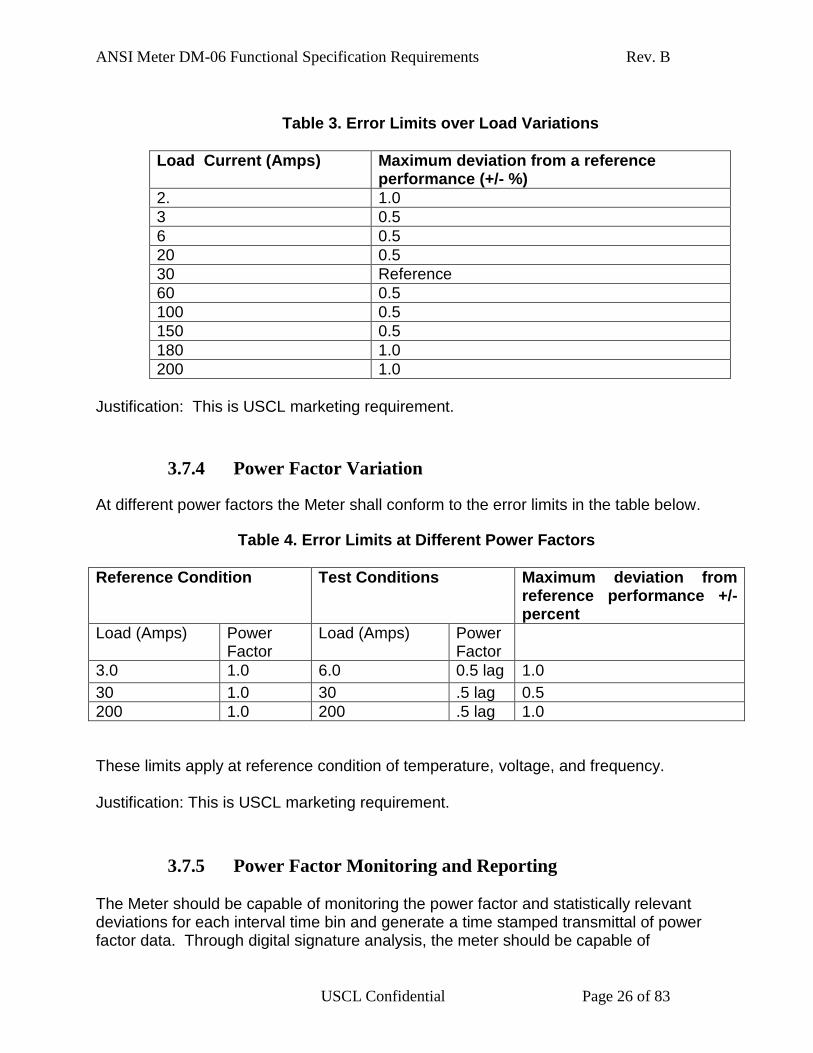

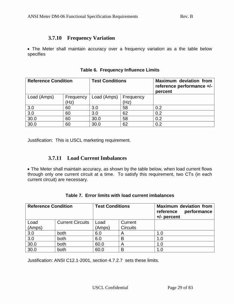


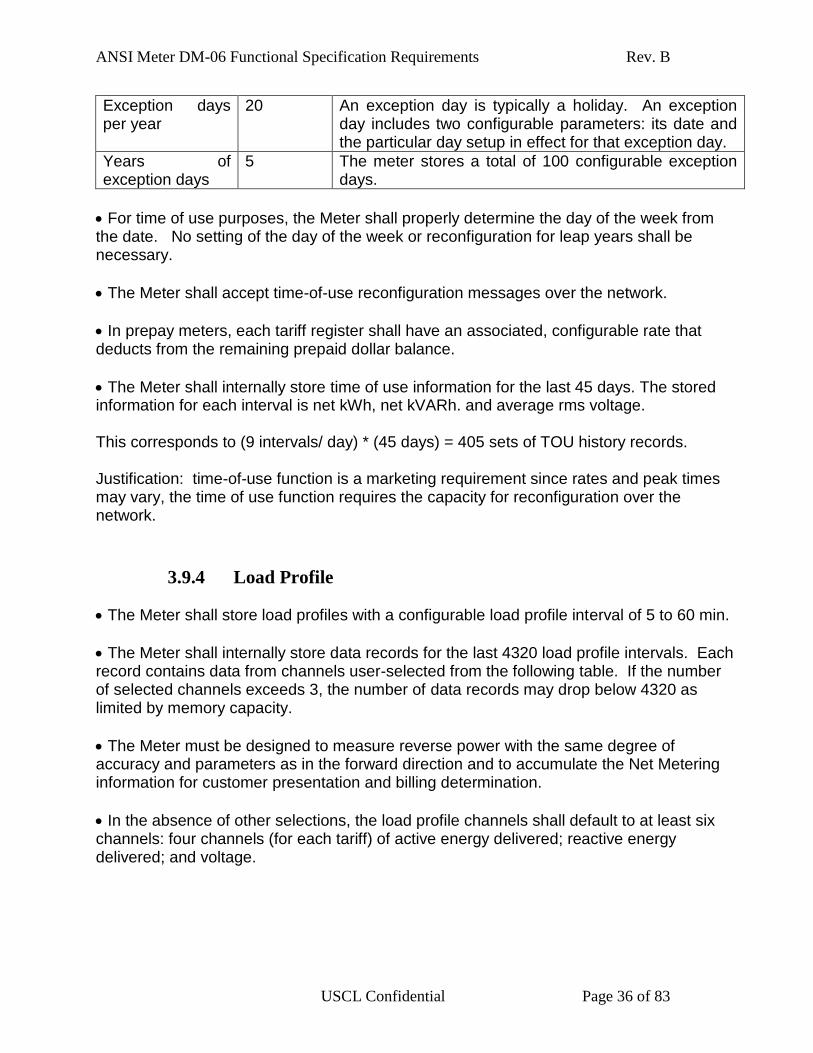
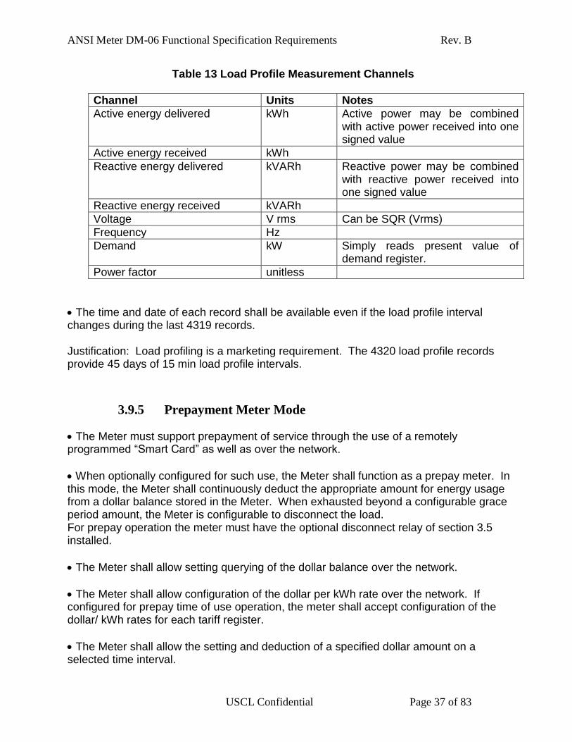


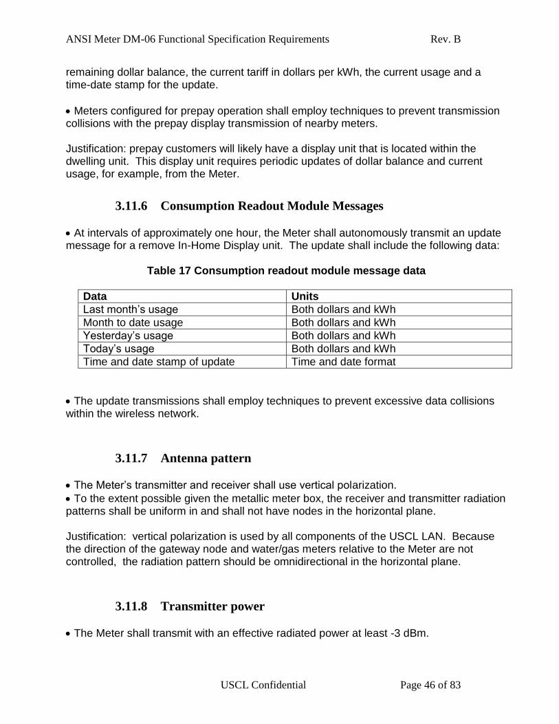


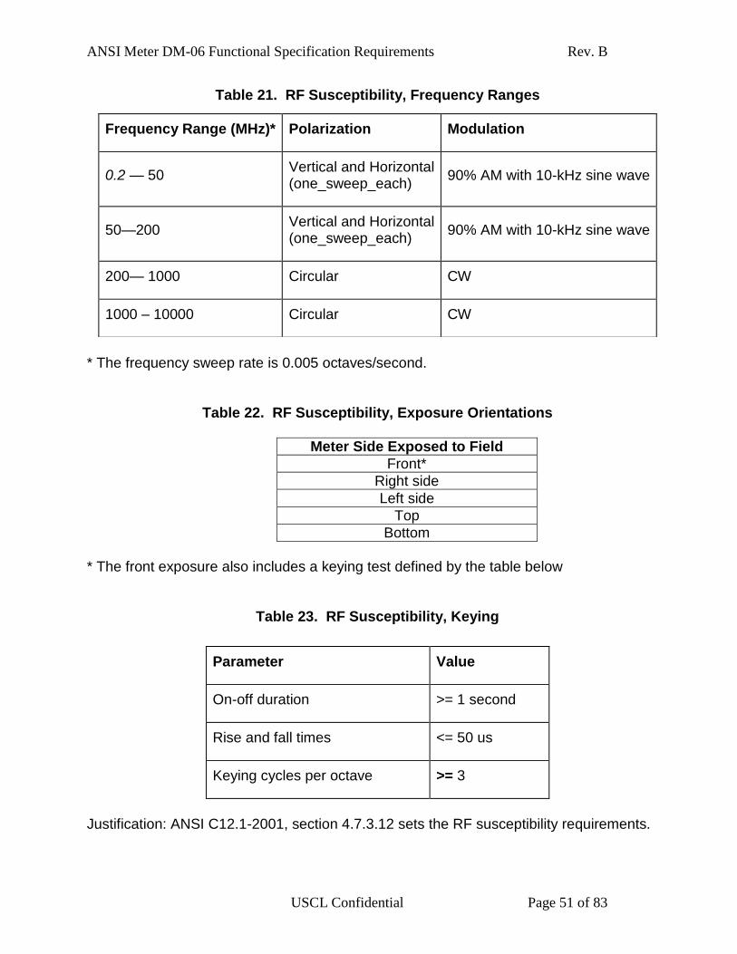
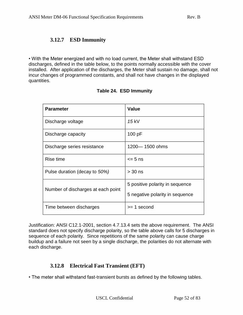
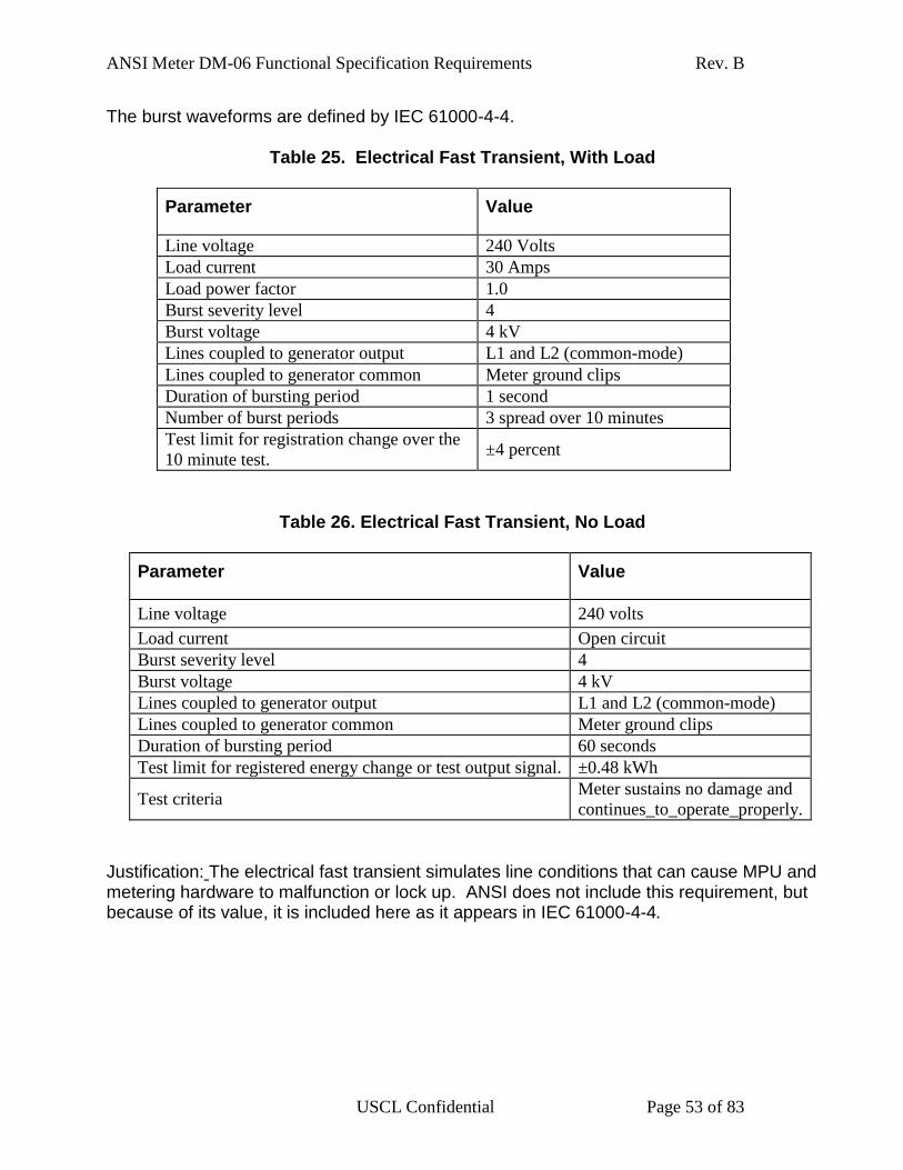


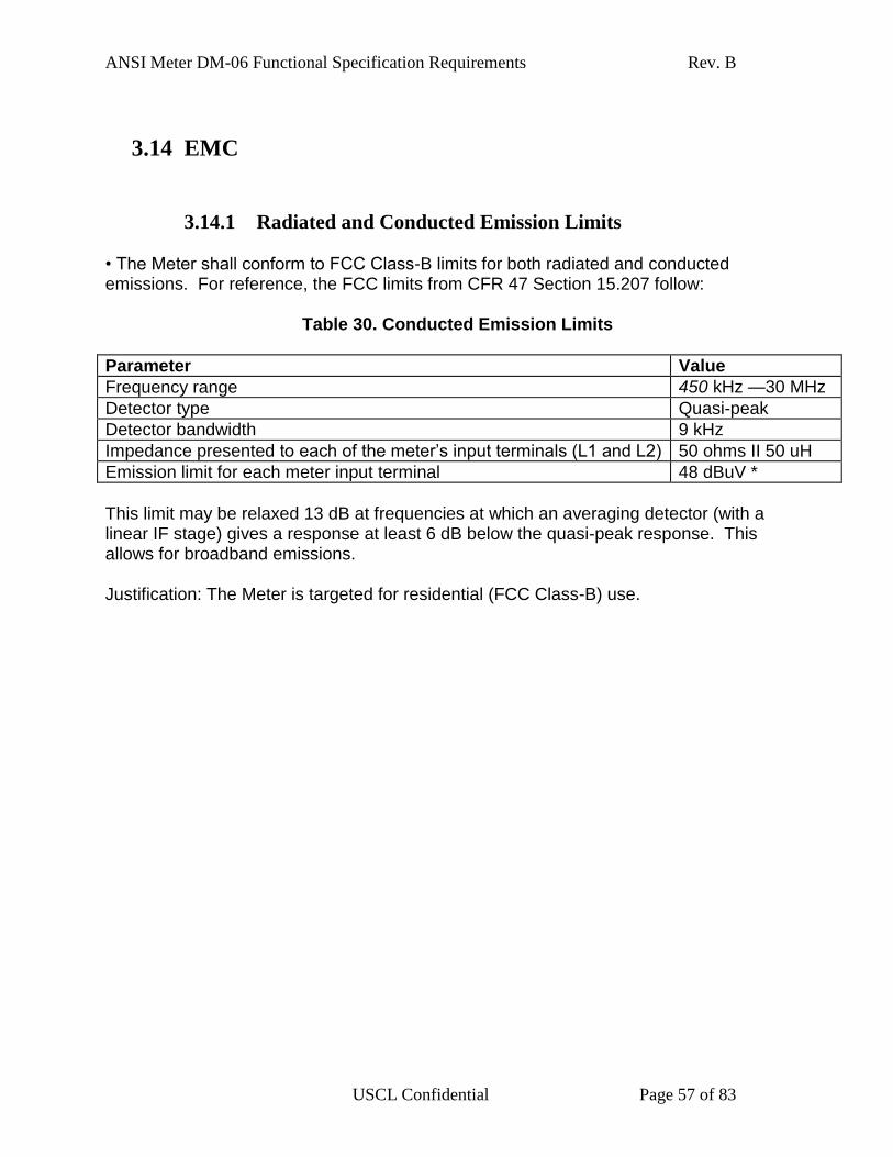


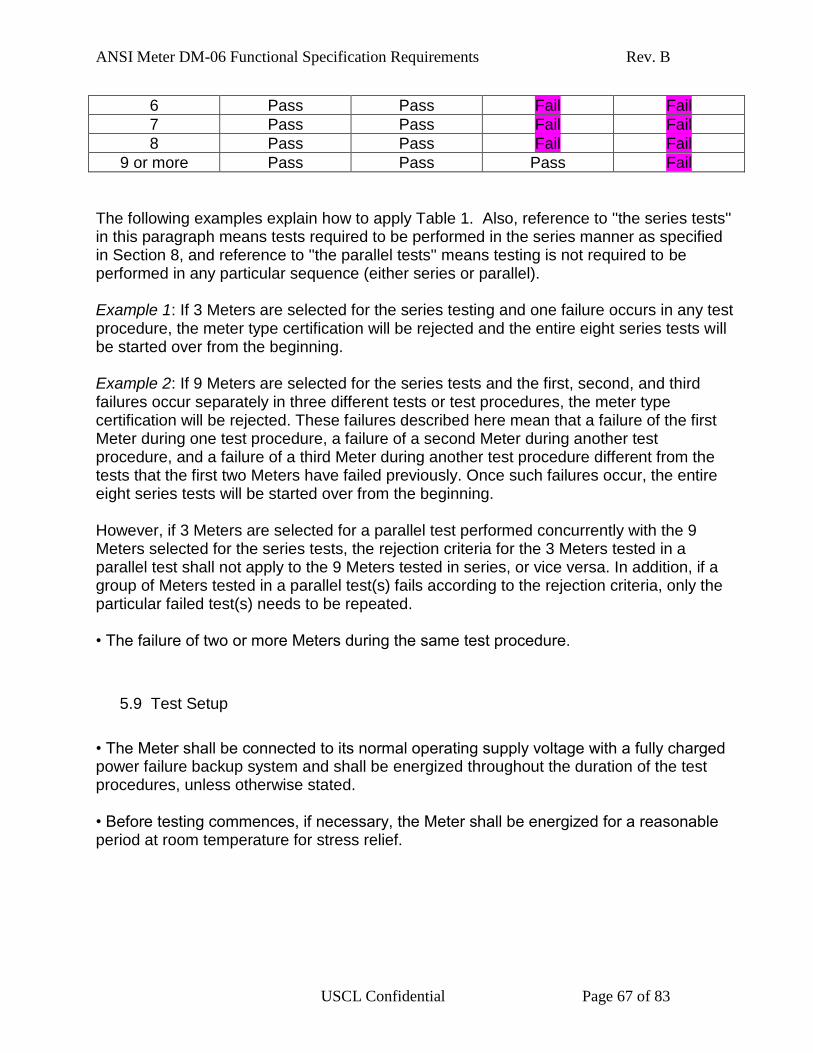


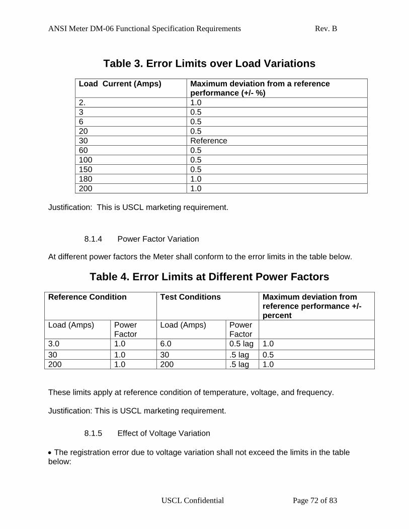

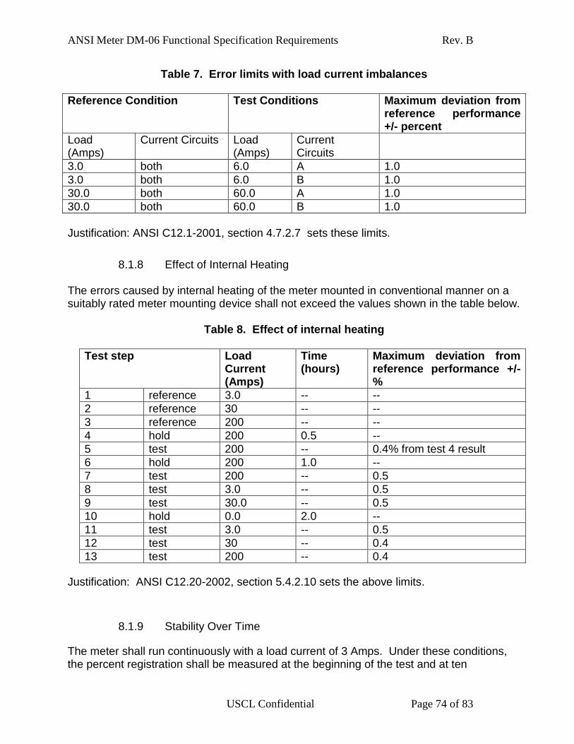


![Effect of Pyrolysis Temperature and Feedstock Type on ...file.scirp.org/pdf/AS_2017090415411158.pdf · mixed for 90 min with 1.0 g of sample [16]. pH-meter (Digimed DM-23) and conductivity-meter](https://static.documents.pub/doc/80x56/5c30034909d3f2e17f8b4568/effect-of-pyrolysis-temperature-and-feedstock-type-on-filescirporgpdfas.jpg)


