+ All Categories
Home > Documents > ANSYS MEMS Related Features - · PDF fileANSYS MEMS Features ... – Manual sequential...

ANSYS MEMS Related Features - · PDF fileANSYS MEMS Features ... – Manual sequential...

Date post: 07-Feb-2018
Category:
Upload: ngokiet
View: 274 times
Download: 1 times
Share this document with a friend
7
1 ANSYS MEMS Features MEMSCAP ® Yiching Liang March 6, 2002 2 2 Finite Element Analysis ¤ 3D models built and exported from MEMS Pro .ANF format: ANSYS neutral format .SAT format: ACIS text format (compatible with most FEA, RF & solvers) ¤ Preprocessing in ANSYS Boundary conditions/loads – Meshing Material/element properties ¤ ANSYS solver ¤ MEMS Pro add-ons in ANSYS 3D to layout Reduced order modeler 3 3 ANSYS MEMS Initiative ¤ ANSYS/Multiphysics ¤ MEMS analysis requirements Devices are inherently multiphysics System of units applicable to small scale Meshing of high aspect ratio devices & features Unique material properties Lumped parameter extraction (into SPICE, VHDL-A/MS) Capability to model large field domains associated with electromagnetics & CFD 4 4 ANSYS MEMS Related Features ¤ Electrostatics ¤ Electrostatic-Structural Coupling ¤ Trefftz Electrostatics ¤ Capacitance Matrix Extraction ¤ Reduced Order Macro Modeling ¤ Piezoelectric ¤ Pre-stressed modal ¤ Fluid-Structural Coupling ¤ Free Surface Fluids ¤ High Frequency Electromagnetics ¤ Composite Beams ¤ Initial/Residual Stress ¤ System of Units 5 5 Electrostatics ¤ Important in MEMS To determine both capacitance and electrostatic forces Typically used to actuate devices such as comb drives and switches ¤ Open domain modeled either using infinite boundary elements (INFIN110, and INFIN111) or Trefftz domain technology 6 6 Adaptive P-Elements ¤ 3D P-elements for electrostatics SOLID128 Brick/Wedge elements SOLID127 Tetrahedral elements ¤ Polynomial order of element increased automatically to satisfy convergence to a prescribed degree of accuracy P-order may extend from 2 - 8 ¤ Supports All electrostatics boundary conditions and loads node coupling and constraint equations Trefftz Domain & CMATRIX.
Transcript

1

ANSYS MEMS Features

MEMSCAP®

Yiching LiangMarch 6, 2002

22

Finite Element Analysis¨ 3D models built and exported from MEMS Pro

– .ANF format: ANSYS neutral format– .SAT format: ACIS text format (compatible with most FEA, RF &

solvers)

¨ Preprocessing in ANSYS– Boundary conditions/loads– Meshing– Material/element properties

¨ ANSYS solver¨MEMS Pro add-ons in ANSYS

– 3D to layout– Reduced order modeler

33

ANSYS MEMS Initiative¨ ANSYS/Multiphysics¨MEMS analysis requirements

– Devices are inherently multiphysics– System of units applicable to small scale– Meshing of high aspect ratio devices & features– Unique material properties– Lumped parameter extraction (into SPICE, VHDL-A/MS)– Capability to model large field domains associated with

electromagnetics & CFD

44

ANSYS MEMS Related Features¨ Electrostatics¨ Electrostatic-Structural Coupling¨ Trefftz Electrostatics¨ Capacitance Matrix Extraction¨ Reduced Order Macro Modeling¨ Piezoelectric ¨ Pre-stressed modal¨ Fluid-Structural Coupling¨ Free Surface Fluids¨ High Frequency Electromagnetics¨ Composite Beams¨ Initial/Residual Stress¨ System of Units

55

Electrostatics¨ Important in MEMS

– To determine both capacitance and electrostatic forces – Typically used to actuate devices such as comb drives and

switches

¨ Open domain modeled either using infinite boundary elements (INFIN110, and INFIN111) or Trefftz domain technology

66

Adaptive P-Elements¨ 3D P-elements for electrostatics

– SOLID128 Brick/Wedge elements– SOLID127 Tetrahedral elements

¨ Polynomial order of element increased automatically to satisfy convergence to a prescribed degree of accuracy– P-order may extend from 2 - 8

¨ Supports – All electrostatics boundary conditions

and loads– node coupling and constraint equations– Trefftz Domain & CMATRIX.

2

77

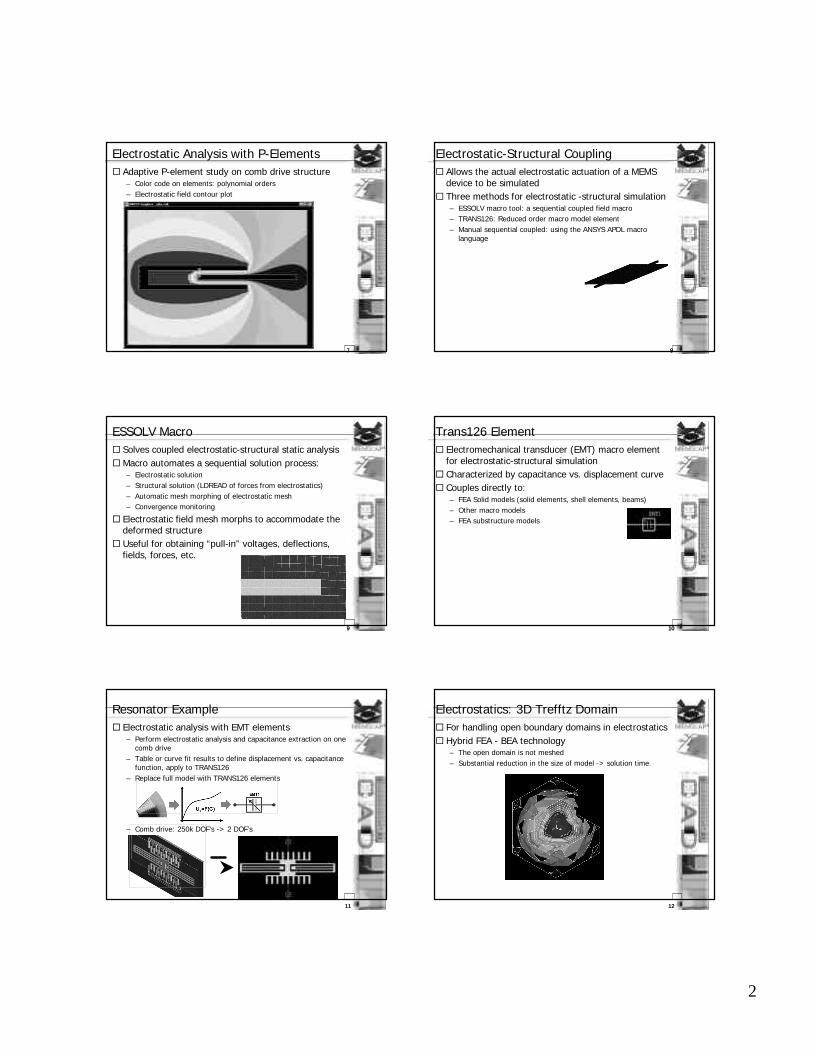
Electrostatic Analysis with P-Elements¨ Adaptive P-element study on comb drive structure

– Color code on elements: polynomial orders– Electrostatic field contour plot

88

Electrostatic-Structural Coupling¨ Allows the actual electrostatic actuation of a MEMS

device to be simulated ¨ Three methods for electrostatic -structural simulation

– ESSOLV macro tool: a sequential coupled field macro– TRANS126: Reduced order macro model element– Manual sequential coupled: using the ANSYS APDL macro

language

99

ESSOLV Macro¨ Solves coupled electrostatic-structural static analysis¨Macro automates a sequential solution process:

– Electrostatic solution– Structural solution (LDREAD of forces from electrostatics)– Automatic mesh morphing of electrostatic mesh – Convergence monitoring

¨ Electrostatic field mesh morphs to accommodate the deformed structure

¨ Useful for obtaining “pull-in” voltages, deflections, fields, forces, etc.

1010

Trans126 Element¨ Electromechanical transducer (EMT) macro element

for electrostatic-structural simulation¨ Characterized by capacitance vs. displacement curve¨ Couples directly to:

– FEA Solid models (solid elements, shell elements, beams)– Other macro models– FEA substructure models

1111

Resonator Example¨ Electrostatic analysis with EMT elements

– Perform electrostatic analysis and capacitance extraction on onecomb drive

– Table or curve fit results to define displacement vs. capacitance function, apply to TRANS126

– Replace full model with TRANS126 elements

– Comb drive: 250k DOF’s -> 2 DOF’s

1212

Electrostatics: 3D Trefftz Domain¨ For handling open boundary domains in electrostatics ¨ Hybrid FEA - BEA technology

– The open domain is not meshed– Substantial reduction in the size of model -> solution time

3

1313

Trefftz Method¨May be used to connect multiple finite element

electrostatic field domains– Eliminating the need to mesh the field regions between

component regions

¨ Electrostatic field around two charged spheres:

Spheres with individual finite element meshes “connected” by a Trefftz domain.

1414

Trefftz Example¨ Example: charged, isolated sphere in free space

– 200 DOF’s– Within 3% of closed form solution

1515

Trefftz Convergence Characteristics ¨ Infinite elements vs. Trefftz domain

0

1

2

3

4

5

6

7

8

9

1 2 3 4 5 6 7 8 9 10

Mesh Refinement Parameter

% E

rro

r (C

apac

itan

ce)

Infinte Elements

Trefftz Domain

1616

CMATRIX Macro¨ Automates computation of systems capacitance matrix

– Extracts capacitance change as a function of device displacement

¨ Applicable to any number of conductors/dielectric materials

¨ Derives ground and lumped matrices– Lump matrix provides the self and mutual capacitance between

conductors.

¨ Useful for extracting lumped capacitance for use in system level circuit-simulations

1717

Comb Drive Example¨ Cross-section electric field contour plots for an

analysis on a small section (2 teeth) of a comb drive¨ Contour plots shows electric fields used to compute

the self and mutual capacitance

P22

P12

P11

1818

CMATRIX Example Output

¨ The results can be listed on screen, output to a file, or accessed by the ANSYS APDL macro language

¨ Lumped capacitance can be used in – System level simulation– Input to ANSYS Trans126 EMT element

4

1919

Macro Model Elements¨ Simplified representations

– Enable rapid simulation of complex MEMS structures

¨Mechanical elements:– Springs, lumped mass, dampers

¨ Circuit elements: – Resistors, capacitors, inductors, transformers, diodes, V/I

sources

2020

Resonator Example¨ Comb drive resonator

– Comb drives: 2 Trans126 elements (EMT1 & EMT2) – Folded springs: 1 spring element (K1)– Proof mass: 1 mass element (M1)– Squeeze film damping: 1 damper element (D1)

2121

Piezoelectric Analysis¨MEMS piezoelectric transducers

– Large deformations – Typically more efficient actuator performance than both

electrostatic and thermal actuators

¨ Piezoelectric capabilities:– Geometric nonlinearities: large deflections/rotations – Stress stiffening– Pre-stressed modal and harmonic analyses– Accurately accounts for changes in the electromechanical field in

bending motion– Direct input of the piezoelectric strain matrix [d] – Calculation of the correction to the permittivity matrix [epsT]-

[epsS]

2222

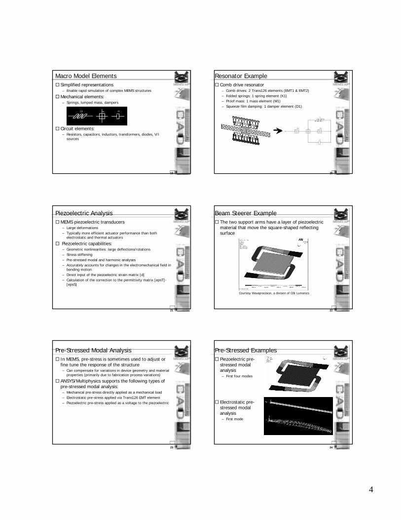
Beam Steerer Example¨ The two support arms have a layer of piezoelectric

material that move the square-shaped reflecting surface

Courtesy Waveprecision, a division of GSI Lumonics

2323

Pre-Stressed Modal Analysis¨ In MEMS, pre-stress is sometimes used to adjust or

fine tune the response of the structure– Can compensate for variations in device geometry and material

properties (primarily due to fabrication process variations)

¨ ANSYS/Multiphysics supports the following types of pre-stressed modal analysis:– Mechanical pre-stress directly applied as a mechanical load– Electrostatic pre-stress applied via Trans126 EMT element– Piezoelectric pre-stress applied as a voltage to the piezoelectric

2424

Pre-Stressed Examples¨ Piezoelectric pre-

stressed modal analysis– First four modes

¨ Electrostatic pre-stressed modal analysis– First mode

5

2525

Coupled Fluid – Structural Analysis¨ Fluidic-structural damping

– At higher velocity the fluid does not have enough time to move and is simply compressed

– Fluid damping changes drastically when the transition from compressible to incompressible flow occurs

– Can change the structural response of MEMS devices

¨ FSSOLV macro automates the simulation– Mesh morphing– Convergence monitoring

¨ Capabilities– Allows for large deformations – Time transient problems: user-specified displacement & velocity

time history for moving body– Computes both lift and drag forces– Incompressible and compressible flow– Equivalent resistance and damping terms can be extracted as

macro models2626

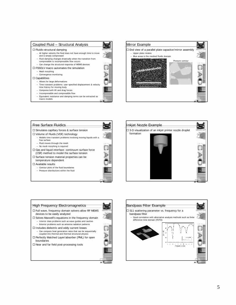
Mirror Example¨ End view of a parallel plate capacitor/mirror assembly

– Upper plate rotates – Blue areas is the meshed fluidic domain

Pressure contour

2727

Free Surface Fluidics¨ Simulates capillary forces & surface tension¨ Volume of Fluids (VOF) technology

– Models time transient problems involving moving liquids with a free surface

– Fluid moves through the mesh– No mesh morphing is required

¨ Gas and liquid interface: continuum surface force (CSF) method to model the surface tension

¨ Surface tension material properties can be temperature dependent

¨ Available results– Contour plots of the fluid boundaries– Pressure distributions within the fluid

2828

Inkjet Nozzle Example¨ 3-D visualization of an inkjet printer nozzle droplet

formation

2929

High Frequency Electromagnetics¨ Full wave, frequency domain solvers allow RF MEMS

devices to be easily analyzed ¨ Solves Maxwell's equations in the frequency domain

– Interior class problems such as wave guides and cavities– Exterior problems such as antenna radiation patterns

¨ Includes dielectric and eddy current losses – Can compute heat generation rates that can be sequentially

coupled into thermal and thermal-structural physics

¨ Perfectly Matched Layer/absorber (PML) for open boundaries

¨ Near and far field post-processing tools

3030

Bandpass Filter Example¨ S11 scattering parameter vs. frequency for a

bandpass filter– Good correlation with alternative analysis methods such as finite

difference time domain (FDTD)

6

3131

Composite Beams¨ Arbitrary beam cross sections with multiple materials

– Multi-layered nature of surface micromachined MEMS devices

¨ Eliminates the need to mesh the volume of a complex geometry for a structural analysis– Dramatically reduces model size and computation time

¨ For structural analysis only– Static displacement – Time transient– Dynamic analysis

3232

Composite Resonator Example¨ Comb drive fingers & frame are modeled using

composite beams– Model consists of ~100 beam elements

3333

Initial Stress¨ Residual stresses: different thermal properties of each

material/layer – Sometimes used as a design feature

¨ Allows direct specification of a constant state of residual stress in each material– GUI or text file input

3434

Optical Grating Device Example¨ The effect of initial stress in the structural polysilicon

layer of a optical grating device– Deformation ~ 50 nm

3535

Systems of Units¨MKS units are not suitable for MEMS¨ ANSYS provides two systems of units suitable for

MEMS simulation:– uMKSV (micrometer, kilogram, second, volt, pico-ampere)– uMVSfA (micrometer, volt, second, femto-ampere, gram)

¨ Unit of length is in µm – Material properties are scaled

¨ Sample conversion tables

3636

Analysis Example: Thermal actuator¨ Beam actuated by thermal

expansion

SEM Image courtesy of Victor Bright, U Col. Boulder.

7

3737

Analysis Example: Electrostatic Mirror¨ Electrostatically actuated

mirror– Surrounding air also meshed

3838

Analysis Example: Accelerometer¨ Time transient analysis

3939

Analysis Example: Linear Resonator¨Modal analysis

Images courtesy of Russell DeAnna, NASA.

4040

Analysis Example: Linear Resonator¨ Electrostatic-structural analysis

4141

Analysis Example: Microfluidic Channel¨ Non Newtonian flow

120 µm

4242

Analysis Example: Microfluidic Valve¨Microfluidic valve / resonator


Recommended