ANTARES: a system of underwater sensors looking for neutrinos Miguel Ardid IGIC- Universitat Politècnica de València on behalf of the ANTARES Collaboration • Introduction • Detector overview • Optical modules • Data acquisition system • Calibration system • Construction milestones & schedule • Summary and conclusions UNWAT – SENSORCOMM Valencia, 18th October 2007
Transcript
ANTARES: a system of underwater sensors looking
for neutrinosMiguel Ardid
IGIC- Universitat Politècnica de València
on behalf of the ANTARES Collaboration
• Introduction• Detector overview• Optical modules• Data acquisition system• Calibration system• Construction milestones & schedule• Summary and conclusions
UNWAT – SENSORCOMM Valencia, 18th October 2007
ANTARES
• ANTARES (Astronomy with a Neutrino Telescope and Abyss environmental RESearch) Collaboration is deploying a 2500 m deep 0.1 km2 underwater neutrino telescope in the Mediterranean Sea
• It is the largest neutrino telescope under construction in the northern hemisphere.
• The aim of the telescope is to detect high energy neutrinos, which are elusive particles expected from a multitude of astrophysical sources.
• ANTARES also aims to provide a research infrastructure for deep sea scientific observations.
M. Ardid for ANTARES CollaborationUNWAT – SENSORCOMMValencia, 18th October 2007 Introduction
M. Ardid for ANTARES CollaborationUNWAT – SENSORCOMMValencia, 18th October 2007 Introduction
Why neutrino astronomy?
Photons: absorbed on dust and radiationProtons/nuclei: deviated by magnetic fields, reactions with radiation
1 parsec (pc) = 3.26 light years (ly)
gammas (0.01 - 1 Mpc)
protons E>1019 eV (10 Mpc)
protons E<1019 eV
neutrinos
Cosmic accelerator
M. Ardid for ANTARES CollaborationUNWAT – SENSORCOMMValencia, 18th October 2007 Introduction
Why neutrino astronomy? • Neutrinos (ν’s) are elementary particles:
– Extremely small mass, no electric charge, very small interaction difficult to detect
– Are produced in nuclear fusion (e.g. stars) or fission (e.g. nuclear power plants) processes
– From Sun reaching Earth ~ 1011 ν/cm2
• Neutrinos traverse space without deflection or attenuation
– they point back to their sources (Search for astrophysical point sources)
– they allow for a view into dense environments
– they allow us to investigate the universe over cosmological distances (Search for Big Bang relics)
• Neutrinos are produced in high-energy hadronic processes→ distinction between electron and proton acceleration.
• Neutrino is a good key for particle physics & cosmology
– Magnetic monopoles, topological defects, Z bursts, nuclearites, …
M. Ardid for ANTARES CollaborationUNWAT – SENSORCOMMValencia, 18th October 2007 Introduction
č
43°Sea floor
p
p,
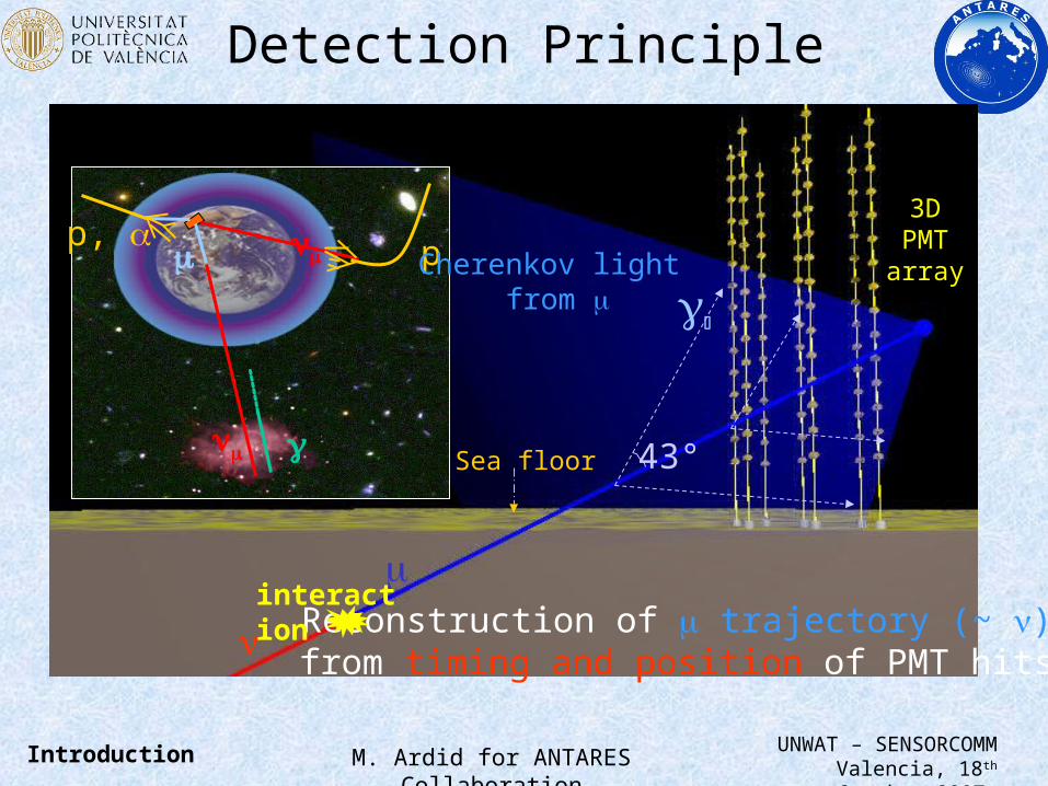
Reconstruction of trajectory (~ ) from timing and position of PMT hits
interaction
Cherenkov light from
3D PMTarray
Detection Principle
M. Ardid for ANTARES CollaborationUNWAT – SENSORCOMMValencia, 18th October 2007
Introduction
Why so large? so deep? Why …?
• Why so large? Neutrino detection requires huge target masses due to the low probability of interaction → use naturally abundant materials (water, ice)
• Why so deep? A large shield is needed in order to avoid masking from other cosmic particles → deep inside the earth
• Why so many optical elements? In order to reconstruct the muon track, the Cherenkov light should be detected. Attenuation length of light in water = 52 m.
• Why calibration systems? For the muon reconstruction a good accuracy of the position of the optical sensors is needed (~ 10 cm) together with a good timing resolution (< 1 ns)
M. Ardid for ANTARES CollaborationUNWAT – SENSORCOMMValencia, 18th October 2007 Introduction
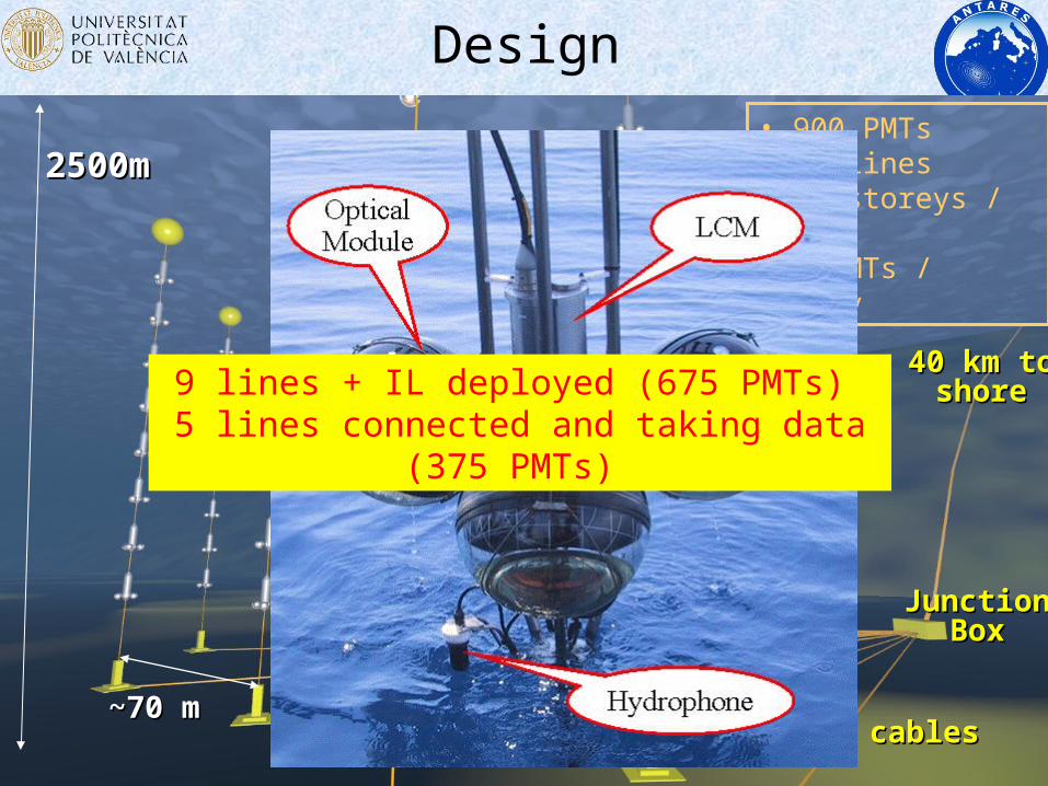
9 lines + IL deployed (675 PMTs) 5 lines connected and taking data (375 PMTs)
Design
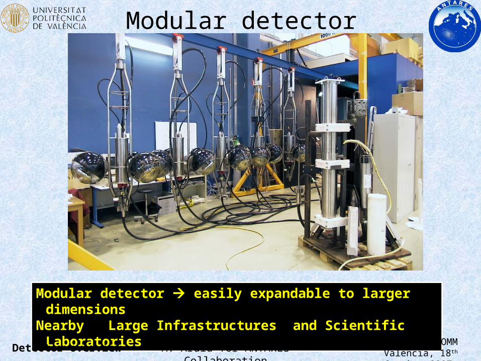
Modular detector easily expandable to larger dimensionsNearby Large Infrastructures and Scientific Laboratories
Modular detector
M. Ardid for ANTARES CollaborationUNWAT – SENSORCOMMValencia, 18th October 2007 Detector overview
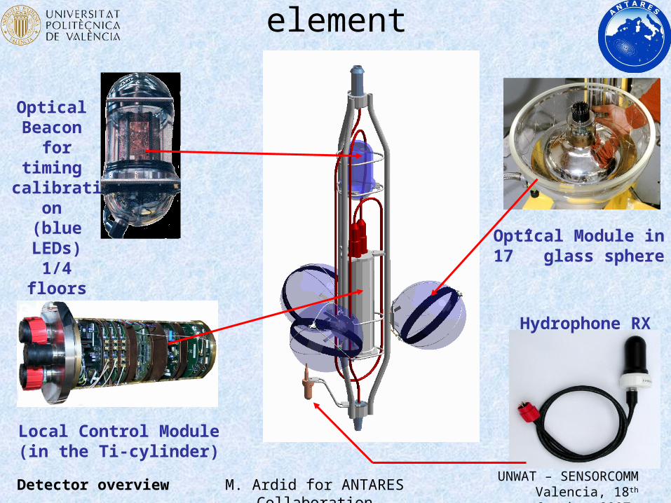
Hydrophone RX
Local Control Module (in the Ti-cylinder)
Optical Beacon
for timing calibratio
n (blue LEDs)
1/4 floorsOptical Module in17” glass sphere
Storey: Basic detector element
M. Ardid for ANTARES CollaborationUNWAT – SENSORCOMMValencia, 18th October 2007 Detector overview
Optical Modules
M. Ardid for ANTARES CollaborationUNWAT – SENSORCOMMValencia, 18th October 2007 Optical Modules
Optical ModulesBlow-up of an Optical Module
Gel
PMT
-metalcage
Base
LED
Sensitive area 500 cm2
Transit time spread < 3.6 ns (FWHM)
Dark count (@ 1/3 SPE) < 10 kHz Peak/valley > 2
PMT: 10”Hamamatsu R7081-20
Main specs
The 900 PMT’s have been fully characterized
0
1
2
3
4
0 100 200 300 400 500 600 700 800 900
TT
S (
ns)
TTSSpecs: < 3.6 ns
0
1
2
3
4
0 100 200 300 400 500 600 700 800 900
P/V
P/VSpecs: > 2
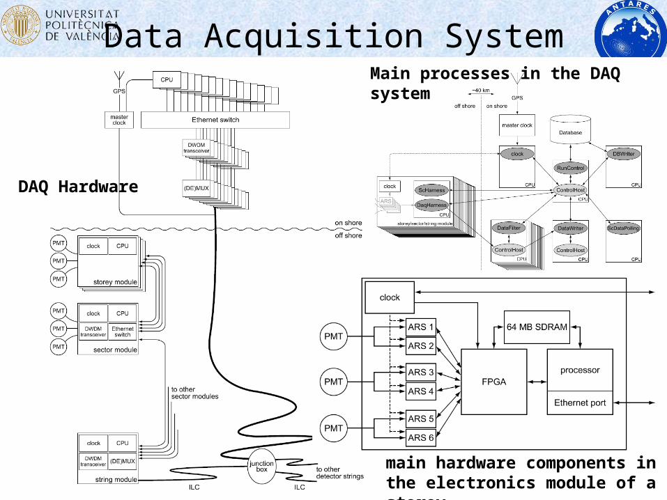
Data Acquisition System
DAQ Hardware
main hardware components in the electronics module of a storey
Main processes in the DAQ system
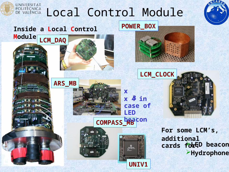
Local Control Module
COMPASS_MB
ARS_MB
LCM_DAQ
POWER_BOX
UNIV1
Inside a Local Control Module
x 3x 4 in case of LED beacon
LCM_CLOCK
For some LCM’s, additional cards for:
LED beaconHydrophone
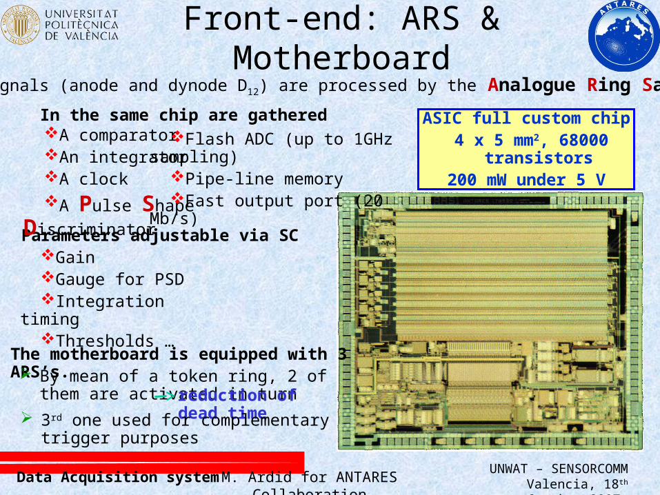
Front-end: ARS & MotherboardThe PMT signals (anode and dynode D12) are processed by the Analogue Ring Sampler
ASIC full custom chip 4 x 5 mm2, 68000 transistors
200 mW under 5 V
In the same chip are gathered
Parameters adjustable via SC
A comparatorAn integratorA clockA Pulse Shape
Discriminator
GainGauge for PSDIntegration timingThresholds …
The motherboard is equipped with 3 ARS’s. By mean of a token ring, 2 of them are
activated in turn reduction of dead time 3rd one used for complementary trigger
purposes
Flash ADC (up to 1GHz sampling)
Pipe-line memoryFast output port (20 Mb/s)
M. Ardid for ANTARES CollaborationUNWAT – SENSORCOMMValencia, 18th October 2007 Data Acquisition system
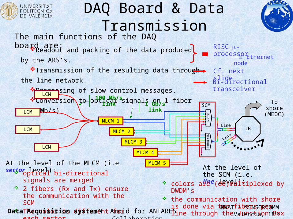
DAQ Board & Data TransmissionThe main functions of the DAQ board are:
Readout and packing of the data produced by the ARS’s.
Transmission of the resulting data through the line network.
Processing of slow control messages.
Conversion to optical signals on 1 fiber (100 Mb/s)
At the level of the MLCM (i.e. sector level):
RISC-processor
Ethernet node
Bi-directional transceiver
Cf. next slide
LCM
LCM
LCM
LCM
MLCM 1
100 Mb/s link
optical bi-directional signals are merged 2 fibers (Rx and Tx) ensure the
communication with the SCM The color is different for each sector
SCM
MLCM 2
MLCM 3
MLCM 4
MLCM 5
1 Gb/s link
At the level of the SCM (i.e. line level):
colors are (de)multiplexed by DWDM’s the communication with shore is done via
two fibers per line through the Junction Box
MUX
deMUX
To shore (MEOC)
JBLine 1
Line
2
M. Ardid for ANTARES CollaborationUNWAT – SENSORCOMMValencia, 18th October 2007 Data Acquisition system
Slow control
Dedicated -controller with ADC’s and DAC’s
In combination with the acoustic positioning:
positions in space of the optical modules
Managed by the main processorMessages (requests and answers) are interleaved with ARS data (same fiber)
to measure temperatures and humidity to command/monitor high voltages on PMT formatting of data an interface with compass/inclinometers
Dedicated circuit with:
Main performances:.5 to 1 for compass bearing.2 for tilt angles1 T for magnetic field
TCM2
2-D inclinometers for roll and pitch measurements
3-D magnetometers for compass bearing
reconstruction of the line shape
Main tasks:Configuration of the detector (for instance ARS’s)Supervision of the state of the detector: temperature, voltages, consumption …
Data Acquisition system
Calibration systems
• Main calibration systems are presented in other talks: – Positioning Calibration (P. Keller’s talk)
• To determine and monitor the position of optical modules
– Timing Calibration (F. Salesa’s talk)• To know the time offsets and get a good timing resolution
– Instrumentation Line + Acoustic detection (R. Lahmann’s talk)
• Monitor environmental and physical variables that could play a role in any system of the telescope
• Equipment for marine science research
• Study the viability of the acoustic detection of neutrinos
M. Ardid for ANTARES CollaborationUNWAT – SENSORCOMMValencia, 18th October 2007 Calibration systems
Construction milestones
• 1996-1999: R&D and site evaluation period.• 1999-2004: Prototype lines• 2004-2005: Final design line evaluation: Line0 (test of
mechanics) & MILOM (Mini Instrumentation Line with Optical Modules)
• February 2006-October 2007: 9 lines + IL deployed, 5 lines connected and operational, starts standard operation
• March 2008: The whole detector will be finished and ready to work at full efficiency for science operation
M. Ardid for ANTARES CollaborationUNWAT – SENSORCOMMValencia, 18th October 2007 Construction Milestones
Line 1 deployment
Construction Milestones
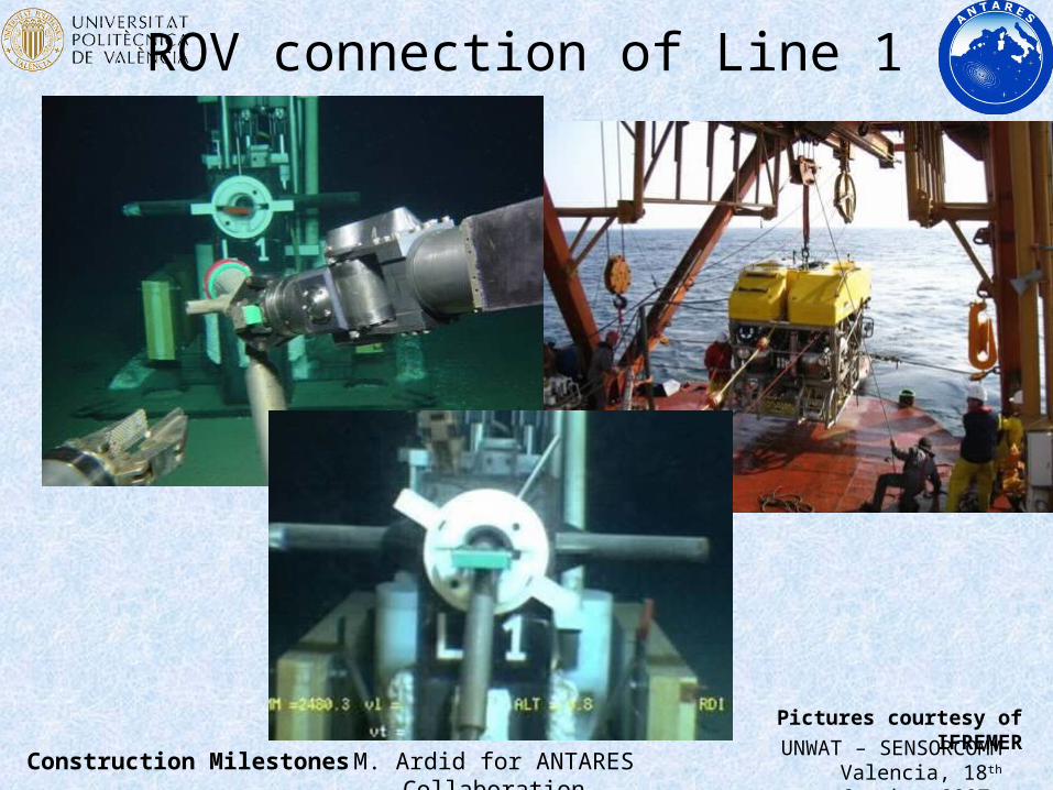
ROV connection of Line 1
M. Ardid for ANTARES CollaborationUNWAT – SENSORCOMMValencia, 18th October 2007 Construction Milestones
Pictures courtesy of IFREMER
Downgoing muon
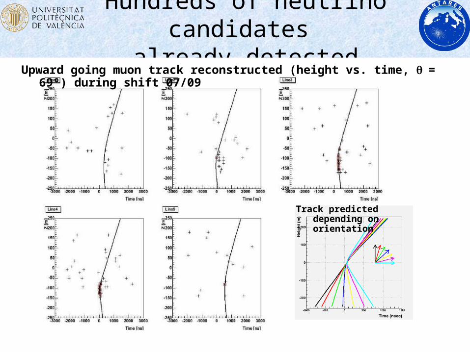
Hundreds of neutrino candidates already detected
M. Ardid for ANTARES CollaborationUNWAT – SENSORCOMMValencia, 18th October 2007 Construction Milestones
Upward going muon track reconstructed (height vs. time, = 69º) during shift 07/09
Track predicted depending on orientation
Summary and conclusions
M. Ardid for ANTARES CollaborationUNWAT – SENSORCOMMValencia, 18th October 2007
• ANTARES Collaboration pursued the challenge of building an undersea neutrino telescope as a sophisticated and precise system of underwater sensors in a hostile environment
• The design, construction and first results have been shown
• After a hard job, there is now almost half neutrino telescope operational and working within specifications, and will be completed early next year.
• For the first time, an undersea neutrino detector (ANTARES) “sees” neutrinos (most likely atmospherics)
• New challenge: KM3NeT, a cubic kilometre undersea neutrino telescope (see C. Bigongiari’s talk)
Summary and conclusions
ANTARES: a system of underwater sensors looking for
neutrinos
Thank you for the attention
M. Ardid for ANTARES CollaborationUNWAT – SENSORCOMMValencia, 18th October 2007 The End