ANTENNA FACTBOOK by Bob Grove W8JHD Founder and President, Grove Enterprises Founder and Publisher, Monitoring Times Copyright 1995, Revised 2006 ACKNOWLEDGMENTS To the American Radio Relay League (ARRL) for their patient consultation and meticulous proofreading; to "Kurt N. Sterba," whose barbs in print have laid asunder a number of myth makers; and to my wife, Judy, for her patience and understand while a I prepared this missal instead of paying the attention to her that she richly deserves.
Transcript
ANTENNA FACTBOOKby Bob Grove W8JHD
Founder and President, Grove EnterprisesFounder and Publisher, Monitoring Times
Copyright 1995, Revised 2006
ACKNOWLEDGMENTSTo the American Radio Relay League (ARRL) for their patient consultation and meticulous proofreading; to "Kurt N. Sterba," whose barbs in print have laid asunder a number of myth makers; and to my wife, Judy, for her patience and understand while a I prepared this missal instead of paying the attention to her that she richly deserves.
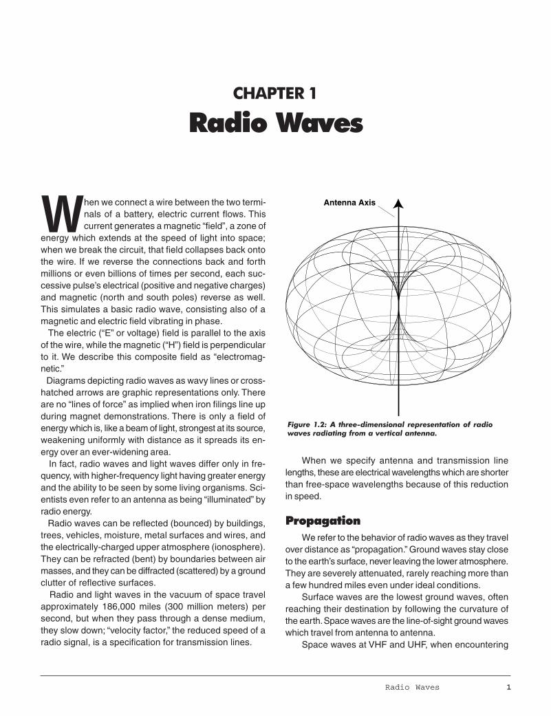
Figure 1.2: A three-dimensional representation of radiowaves radiating from a vertical antenna.
Radio Waves 1
CHAPTER 1
Radio Waves
When we connect a wire between the two termi-nals of a battery, electric current flows. Thiscurrent generates a magnetic “field”, a zone of
energy which extends at the speed of light into space;when we break the circuit, that field collapses back ontothe wire. If we reverse the connections back and forthmillions or even billions of times per second, each suc-cessive pulse’s electrical (positive and negative charges)and magnetic (north and south poles) reverse as well.This simulates a basic radio wave, consisting also of amagnetic and electric field vibrating in phase. The electric (“E” or voltage) field is parallel to the axisof the wire, while the magnetic (“H”) field is perpendicularto it. We describe this composite field as “electromag-netic.” Diagrams depicting radio waves as wavy lines or cross-hatched arrows are graphic representations only. Thereare no “lines of force” as implied when iron filings line upduring magnet demonstrations. There is only a field ofenergy which is, like a beam of light, strongest at its source,weakening uniformly with distance as it spreads its en-ergy over an ever-widening area. In fact, radio waves and light waves differ only in fre-quency, with higher-frequency light having greater energyand the ability to be seen by some living organisms. Sci-entists even refer to an antenna as being “illuminated” byradio energy. Radio waves can be reflected (bounced) by buildings,trees, vehicles, moisture, metal surfaces and wires, andthe electrically-charged upper atmosphere (ionosphere).They can be refracted (bent) by boundaries between airmasses, and they can be diffracted (scattered) by a groundclutter of reflective surfaces. Radio and light waves in the vacuum of space travelapproximately 186,000 miles (300 million meters) persecond, but when they pass through a dense medium,they slow down; “velocity factor,” the reduced speed of aradio signal, is a specification for transmission lines.
When we specify antenna and transmission linelengths, these are electrical wavelengths which are shorterthan free-space wavelengths because of this reductionin speed.
PropagationWe refer to the behavior of radio waves as they travel
over distance as “propagation.” Ground waves stay closeto the earth’s surface, never leaving the lower atmosphere.They are severely attenuated, rarely reaching more thana few hundred miles even under ideal conditions.
Surface waves are the lowest ground waves, oftenreaching their destination by following the curvature ofthe earth. Space waves are the line-of-sight ground waveswhich travel from antenna to antenna.
Space waves at VHF and UHF, when encountering
Antenna Axis
2 Chapter 1
abrupt weather boundary changes, experience tempera-ture inversions, ducting and other influences which cansignificantly extend ground wave coverage.
At the upper reaches of our atmosphere, ultravioletrays from the sun ionize (electrically charge) the air at-oms, lending the name “ionosphere” to this highest zoneof the earth’s atmosphere. Radio waves which reach these
ionized layers, averaging 25-200 miles high, are called“sky waves.” The lowest regions of the ionosphere, the D and E lay-ers, are influenced directly by sunlight; their effects beginat sunrise, peak at noon, and disappear after sunset. Theyabsorb radio signals—the longer the wavelength (that is,the lower the frequency), the more the absorption. This
explains why daytime reception below about10 megahertz is so poor. But the E layer also reflects shorter-wave-length (higher frequency) signals back to Earth;the higher the frequency, the more the reflec-tion. This is what provides DX (distance) onthe higher shortwave frequencies. Most DX, however, is produced by the nextregion up, the F layer, which retains its electri-cal charge well into the night, reflecting sig-nals back to the earth over great distances. All of these solar influences increase duringsunspot peaks, which occur every 11 years. The earth itself can reflect radio waves, al-lowing a phenomenon called “multihop”—com-binations of earth reflections and ionosphericrefractions producing as many as five skips!Any more skips would be attenuated by iono-spheric absorption and terrestrial scatteringbelow usability. Many radio magazines publish monthly ra-dio propagation forecasts, and a variety of pre-diction computer programs are available, al-lowing the user to plan ahead for the most pro-ductive use of the spectrum.
At VHF and UHF, ionospheric propaga-tion is rare. Some sporadic E skip, lasting froma few minutes to an hour or more, may occurin the 50-200 MHz range. It is caused by er-ratic clouds of ionization at an altitude of 75-100 miles.
The lowest regions of the ionosphere, the D and E layers, are influenced directly bysunlight; their effects begin at sunrise, peak at noon, and disappear after sunset. Theyabsorb radio signals—the longer the wavelength (that is, the lower the frequency), the
more the absorption. This explains why daytime reception below about 10 megahertz is sopoor.
Figure 1.3: Signal propogation is a combination of ground waves and skywaves.
Ionosphere Layers
F2
F1
E
Sky W
ave
Direct Wave
Surface Wave
Ground-reflected Wave
Antenna
SpaceWave
GroundWave
3 Chapter 1
Tropospheric scattering in the E and F2 layers is fairlycommon in the 30-50 MHz spectrum, especially duringthe daytime and during sunspot peaks. It favors the eastin the morning and the west in the afternoon.
PatternsThe “shape” of the field of energy emitted by a trans-
mitting antenna, as well as response by a receiving an-tenna, is known as its pattern. It may be a simple donutshape surrounding the axis of the wire as in a half-wave(or smaller) dipole (“doublet”), or it may be multi-lobed, asin a multiple-wavelength antenna (“longwire”).
The elevation pattern is affected by height aboveground, length of the antenna element(s), and the pres-ence of nearby metal, including other antenna elements.
The elevation of the pattern, variously called “radia-tion angle”, “take-off angle”, “maximum amplitude eleva-tion”, and “launch angle”, is an integral part of an antenna’sgain characteristics (We will discuss gain in Chapter 3).
Figure 1.4: Antennas are designed to favor certain direc-tions, both for transmitting and receiving.
The “shape” of the field of energy emitted by a transmitting antenna, as well as responseby a receiving antenna, is known as its pattern. It may be a simple donut shape
surrounding the axis of the wire as in a half-wave (or smaller) dipole (“doublet”), or it maybe multi-lobed,
as in a multiple-wavelength antenna (“longwire”).
1/4-wave vertical groundplane
Half-wave dipole, looking into the end of the wire
Radiation and ReceptionPattern
Radiation and ReceptionPattern
Radiation and ReceptionPattern
Radiation and ReceptionPattern
Yagi Antenna
EARTH
Antenna Location 4
The lower the frequency, the more the signal is ca-pable of following the contour of the terrain, and the lesslikely it is to be absorbed by trees and foliage. One studyshowed that with dense trees and vertical polarization,attenuation at 30 MHz is about 3 dB, increasing to 10 dBat 100 MHz.
Figure 2.2: The higherthe frequency, theshorter the wave-length and the easierit is for a signal to getthrough an opening inan absorptive orreflective enclosure.
Figure 2.1: Terrain, trees, wiring, metal siding,nearby buildings and other reflective surfacesall affect antenna performance. The lower theantenna, the more obstructed it is likely to be.
very poor antenna location would be an indoorbasement. Signals are unpredictably reflected bymetal and wiring in the structure; nearby electricA
and electronic appliances invite interference to reception;and the earth absorbs transmitted energy as well as re-flects signals upward; and it receives signals from over-head, rather than from the horizon. Nearby trees, build-ings and hills take their toll, too.
Locating an antenna inside a large building with steelframe and metal reinforcements may attenuate signalsup to 25 dB at VHF and UHF, according to one study.Brick walls, slate or tile roofs can account for 6 dB, evenmore when wet. Shorter wavelengths (900 MHz) getthrough small windows in shielded walls where longerwavelengths (150 MHz) do not.
CHAPTER 2
Antenna Location
The Radio HorizonThe Radio HorizonRadio waves, like light waves, follow the line of sight.
Because of the curvature of the earth, higher antennas“see” a farther horizon.
Assuming a flat, unobstructed terrain, the visual hori-zon is about 8 miles for a 30-foot-elevated antenna, in-creasing to only 16 miles at 120 feet! Notice the squarelaw effect: it requires roughly four times the height to gettwice the distance. Once an antenna is high enough to“see” past nearby obstructions, it takes at least doublethat height to notice any improvement.
The lower the frequency, the more radio waves arecapable of following the curvature of the earth beyond thevisual horizon. Typical base-to-mobile communicationsranges are about 50 miles in the 30-50 MHz band, 30miles at 150-174 MHz, 25 miles at 450-512 MHz, and 20miles at 806-960 MHz. Obviously, these distances willvary depending upon radiated power, receiver sensitivity,antenna gain, elevation and location.
Although the higher the antenna the better, coax cablelosses may negate any signal improvement; the higherthe frequency, the worse the losses.
For example, at 450 MHz, extending a 30-foot an-tenna to 60 feet could increase signal strengths by 5 dB,but if you are using common RG-58/U coax, signalstrengths may be attenuated by the same amount, result-ing in no improvement at all! At 800 MHz, using this small-diameter, lossy cable, signals would get worse with height!
Always use low-loss cable like (in increasing perfor-
5 Chapter 2
While ground-mounted verticals are simpler to installthan elevated antennas, nearby obstructions profoundlyaffect their performance.
Because horizontal antennas radiate at right anglesto their axes, they should be elevated at least 1/2 wave-length—higher if possible—as measured at their lowestoperating frequency, to avoid ground effects which forcethe pattern upward. An antenna at that elevation can havea 6 dB (one full S-unit) stronger signal than one only 0.1-0.25 wavelengths above the ground. One-half wavelengthabove the ground at its lowest frequency of operationappears even higher (in wavelengths) at higher frequen-cies because of their shorter wavelengths.
Earth
Earth
End view of antenna
End view of antenna
A
B
Figure 2.3: A high, horizontal antenna over the ground (A)enjoys a more uniform radiation and reception patterntoward the horizon than a low antenna (B) which is distortedupward by ground relfections.
Distance (mi.) = 1.5 x Antenna Ht. (ft.)
Antenna Ht. (ft.) Visual Horizon (mi.) Radio Horizon (mi.)
20 5 650 9 10
100 12 14
Figure 2.4: A reasonable approximation of the visualhorizon; due to groundwave effects, the radio horizonis slightly greater.
Because horizontal antennas radiate at right angles to their axes, they should be elevatedat least 1/2 wavelength--higher if possible--as measured at their lowest operating
frequency, to avoid ground effects which force the pattern upward. An antenna at thatelevation can have a 6 dB (one full S-unit) stronger signal than one only 0.1-0.25
wavelengths above the ground.
������������
Approximately 100'- 200' insulated wire
mance) RG-8/X, RG-8/U, Belden 9913, or1/2" foam (Andrews) Heliax (all 50 ohmcables); or RG-59/U, RG-6/U or RG-11/U(72 ohm cables).
Buried antennasWhile a wire antenna on the ground
or even buried a few inches under the soilis very inferior to an elevated antenna atshortwave and above, it does respond wellto signals below 3 MHz or so. It is virtu-ally immune to lightning, requires nomounting, is essentially invisible, and hasexcellent noise immunity (which probablyaccounts for its good reception).
Such an antenna should be insulation-covered toprevent electrical contact with the soil, and should
be 100-200 feet in length. It is also a goodidea to seal the far end with a dab of sili-
cone rubber to discourage moisturepenetration.
Lightning protection Nothing can withstand a directlightning hit. The best you can ex-pect from a lightning arrestor orsurge protector is to harmlesslyshort-circuit small voltage spikesresulting from nearby hits. Old-style, spark-gap, antenna
Antenna Location 6
LOSS IN dBTYPE IMPEDANCE 1 MHz 30 MHz 150 MHz 450 MHz 1000 MHz
RG-6/U 75 0.5 1.2 2.5 4.2 6.5
R6-8/(foam) 50 0.1 0.9 2.1 3.8 6
RG-8/X(mini) 50 0.5 2 4.5 0.9 13.5
RG-11/U 75 0.3 0.8 1.4 2.6 4.0
RG-58/U 50 0.4 2.5 6 12 17
RG-59/U 75 0.3 2 4.5 8 12
RG-174/U 50 1.9 4 10 21 34
Belden 9913 50 0.1 0.7 1.7 3 4.5
Figure 2.6: An antenna buried just under the surface of the ground may workwell below 2-3 MHz.
Old-style, spark-gap, antenna lightning arrestors were satisfactory for high-voltage-tolerant, tube-type equipment, but not for modern, low-voltage, solid-state equipment.
Gas-discharge tubes which fire at well under 100 volts offer better protection, whileallowing full amateur transmitter power to pass unaffected.
lightning arrestors were satisfactory for high-voltage-tol-erant, tube-type equipment, but not for modern, low-volt-age, solid-state equipment. Gas-discharge tubes whichfire at well under 100 volts offer better protection, whileallowing full amateur transmitter power to pass unaffected. During storms or extended periods of non-use, discon-nect your antenna line from your radio. You may wish toground it or, alternatively, hang the connector away fromthe radio equipment, even hanging it inside a drinking glassfor additional insulation.
Improved lightning protection may be realized by sus-pending the antenna below the top of a well-grounded metalmast (which then becomes a lightning rod), by coiling thecoax for about a dozen turns before it enters the building,and by passing the coax through a ten-foot metal pipewhich is well grounded. Although electrical power line protection is beyond
the scope of this book, highly-effectivemetal-oxide varistors (MOVs) areavailable in strip-line extensioncords, and even for circuit-breakerpanels to protect the whole house.
Figure 2.5: Typical coax losses in dB per 100 feet, assuming ideal conditions.
What is a “ground”? The earth plays an important role in radio sig-nal propagation, but “grounding” your radio equip-ment is not one of them. While attaching thechassis of your radio to a buried conductor inmoist soil may protect you from electrical shock,will drain off static charge buildup, can help dis-sipate nearby lightning-induced spikes, and evenreduce electrical noise pickup, it will not makereceived or transmitted signals stronger. Radio wave travels through space, not throughthe ground except at very close ranges or atextremely low frequencies. It is intercepted bythe antenna metal, not by the soil beneath itwhich absorbs and dissipates the signal as heat. A good electrical ground consists minimallyof two eight-foot metal rods, at least ten feetapart, connected to the radio equipment by ashort length of heavy braid. Moist, mineralizedsoil is best; dry, sandy soil is worst. A radio-frequency (RF) ground, on the otherhand, is more extensive. A vertical antenna maybe thought of as a center-fed dipole turned onits end, and the lower half removed so that wecan mount the remaining element on the groundwhere the coax will be attached. But we mustsomehow supply that missing half of the an-tenna. If we simply bury the needed wire in the ground,the energy that would radiate from that elementis absorbed by the mineralized soil, simply heat-ing it. Such an antenna is sometimes referred toas a “worm warmer!” Instead, we construct a “counterpoise” on orabove the soil, a metallic surface emulating a“perfect” (reflective) earth, composed of radialwires connected to, and extending outward fromthe coax shield at the base of the antennas. How many spokes of wire, and how long? AM
7 Chapter 2����������
To radio room
Ground pipe
Ground strap
10' metal pipe
12 coiled turns
Coax line
Metal
Mastpipe
Antenna
Figure 2.7: A practicalsolution to lightningprotection (see text onpreceding page forexplanation.)
A good electrical ground consists minimally of two eight-foot metal rods, at leastten feet apart, connected to the radio equipment by a short length of heavy braid.
Moist, mineralized soil is best; dry, sandy soil is worst. A radio-frequency (RF)ground, on the other hand, is more extensive.
������������������������
Coax Coax
Verticalantenna
Verticalantenna
Groundpipe
A B
Figure 2.9: Agood radialcounterpoise(A) is alwayspreferable tousing lossyearth (B) in averticalantenna system.
Antenna Location 8
Because current is at its maximum at the feedpoint, density of metal around thebase of the antenna is more important than the length of the radials.
If you have 100 feet of wire, ten 10-foot lengths is betterthan two 50-foot lengths. Receive-only antennas are not so critical.
broadcasters use at least 120; for transmitting pur-poses, you should use at least 16 1/8-wavelengthwires to avoid power losses from soil absorption. Because current is at its maximum at the feedpoint, density of metal around the base of the an-tenna is more important than the length of the radi-als. If you have 100 feet of wire, ten 10-foot lengthsis better than two 50-foot lengths. Receive-only an-tennas are not so critical.
Even a single quarter-wavelength wire providescounterpoise effect; it may be run randomly or even��
����
TRANSCEIVERor RECEIVER TRANSMATCH SCANNER
ANT.SWITCH
Operating Position
Ground bus(1/2" Copper Pipe)
Hose clamp
Braid to equipment
6' to 8' Ground rod
Low-impedanceconductor, asshort as possible, clamped securely
Three-wire grounded power outlets, connected to grounded house electrical system
Figure 2.8: A good ground system utilizes short, large-gauge wire toconnect radio equipment commonly to at least one deep ground rod.
coiled loosely in some cases. Such a wire is often con-nected to the chassis of the transmitter if it is “hot” duringtransmitting as evidenced by painful RF burns when touch-ing the equipment, especially your lip to the mike!
The inverted V antenna is a good example of how tokeep the high-current feed point away from absorptiveand reflective earth by elevating it to the apex of theantenna. The ends of the drooping elements (high-volt-age points) come to within a few feet of the ground wheretheir capacitive interaction with the soil may cause somelength detuning of the antenna, but little signal loss.
Don’t confuse a ground-mounted, counterpoised ver-tical with an elevated ground-plane antenna. On the groundwe are trying to prevent radiation from being absorbed by
9 Chapter 2
At least 900
Supportmast
Coax
1/4 W
avele
ngth1/4 W
avelength
Current node
Voltage node
Insulator
Voltage node
Insulator
Earth
Figure 2:10: The inverted V is a popular dipole configuration.������������������������
Ground-mounted verticalantenna
Elevatedverticalantennawith radials
A B
Figure 2.11: The radial counterpoise on a ground-mountedvertical (A) prevents soil absorption of the radio waves; theradials on an elevated vertical (B) are part of the antennaitself and help shape the pattern.
the soil; an elevated ground-plane antenna, however, be-haves more like a dipole in free space, with the radialssupplying half of the antenna and forming the pattern.
Construction and Size 10
CHAPTER 3
Construction and Size
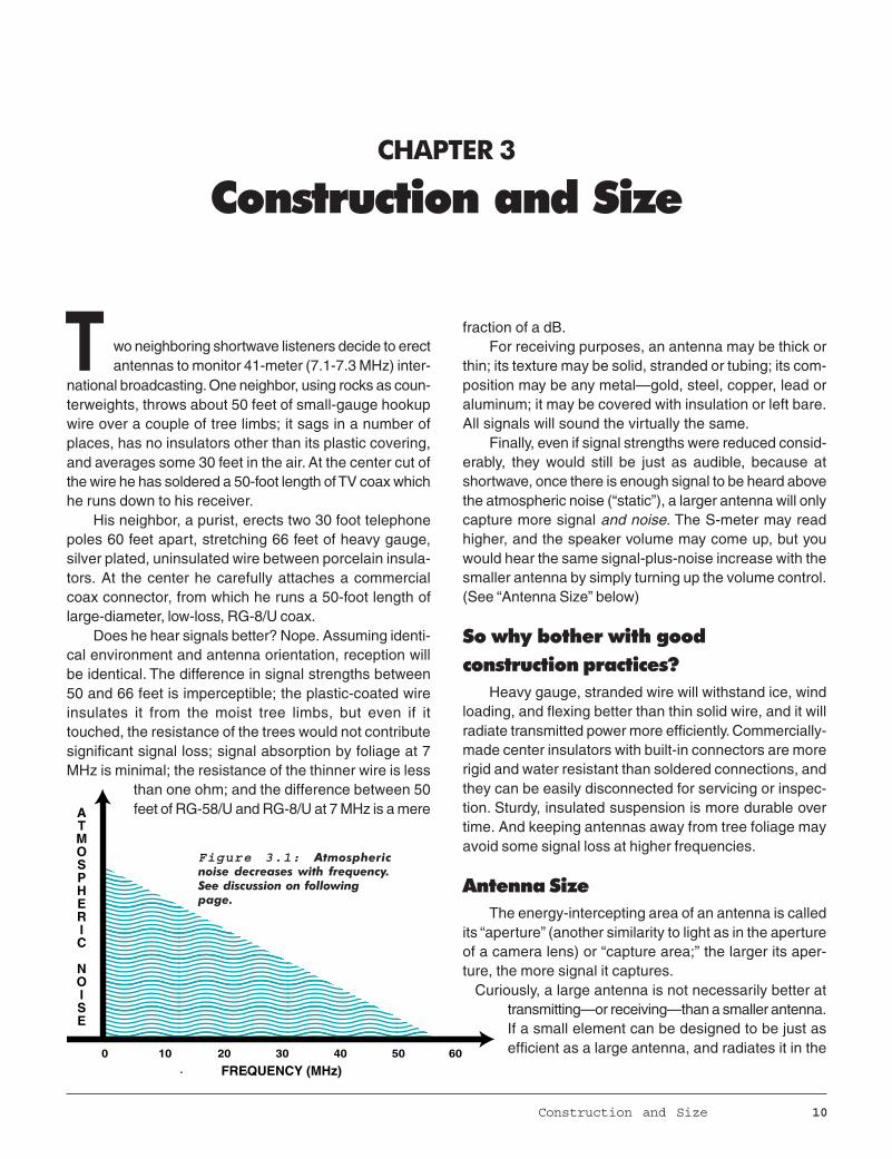
Figure 3.1: Atmosphericnoise decreases with frequency.See discussion on followingpage.
��������������������������������
ATMOSPHERIC
NOISE
FREQUENCY (MHz)0 10 20 30 40 50 60
national broadcasting. One neighbor, using rocks as coun-terweights, throws about 50 feet of small-gauge hookupwire over a couple of tree limbs; it sags in a number ofplaces, has no insulators other than its plastic covering,and averages some 30 feet in the air. At the center cut ofthe wire he has soldered a 50-foot length of TV coax whichhe runs down to his receiver.
His neighbor, a purist, erects two 30 foot telephonepoles 60 feet apart, stretching 66 feet of heavy gauge,silver plated, uninsulated wire between porcelain insula-tors. At the center he carefully attaches a commercialcoax connector, from which he runs a 50-foot length oflarge-diameter, low-loss, RG-8/U coax.
Does he hear signals better? Nope. Assuming identi-cal environment and antenna orientation, reception willbe identical. The difference in signal strengths between50 and 66 feet is imperceptible; the plastic-coated wireinsulates it from the moist tree limbs, but even if ittouched, the resistance of the trees would not contributesignificant signal loss; signal absorption by foliage at 7MHz is minimal; the resistance of the thinner wire is less
than one ohm; and the difference between 50feet of RG-58/U and RG-8/U at 7 MHz is a mere
T wo neighboring shortwave listeners decide to erectantennas to monitor 41-meter (7.1-7.3 MHz) inter-
fraction of a dB.For receiving purposes, an antenna may be thick or
thin; its texture may be solid, stranded or tubing; its com-position may be any metal—gold, steel, copper, lead oraluminum; it may be covered with insulation or left bare.All signals will sound the virtually the same.
Finally, even if signal strengths were reduced consid-erably, they would still be just as audible, because atshortwave, once there is enough signal to be heard abovethe atmospheric noise (“static”), a larger antenna will onlycapture more signal and noise. The S-meter may readhigher, and the speaker volume may come up, but youwould hear the same signal-plus-noise increase with thesmaller antenna by simply turning up the volume control.(See “Antenna Size” below)
So why bother with goodconstruction practices?
Heavy gauge, stranded wire will withstand ice, windloading, and flexing better than thin solid wire, and it willradiate transmitted power more efficiently. Commercially-made center insulators with built-in connectors are morerigid and water resistant than soldered connections, andthey can be easily disconnected for servicing or inspec-tion. Sturdy, insulated suspension is more durable overtime. And keeping antennas away from tree foliage mayavoid some signal loss at higher frequencies.
Antenna SizeThe energy-intercepting area of an antenna is called
its “aperture” (another similarity to light as in the apertureof a camera lens) or “capture area;” the larger its aper-ture, the more signal it captures. Curiously, a large antenna is not necessarily better at
transmitting—or receiving—than a smaller antenna.If a small element can be designed to be just asefficient as a large antenna, and radiates it in the
signal, directivity favors one (or more) direction(s) at theexpense of others. This reduces overall pickup (bettersignal-to-noise-ratio), concentrating on a target directionfor receiving and/or transmitting.
Such pattern re-direction often refers to “front-to-backratio” and “side lobe rejection”, illustrating how improve-ment in one direction comes at the (desirable) loss inothers.
The pattern can be shaped by adding parasitic (un-connected to the feed line) elements called reflectors and
11 Chapter 3
same pattern, there is no benefit in using a larger antennaunless it offers “gain.”
Similarly, all antennas of the same size—wire dipoles,folded dipoles, fans, trap antennas, cages, or any other—radiate the same amount of power. Their relative advan-tages come from pattern directivity.
The U.S. Coast Guard found several decades ago thata five-foot antenna was adequate for HF reception 100%of the time. Remember, the purpose of an antenna is todetect enough signal to overcome the receiver’s own in-ternally-generated noise; once that is accomplished,more signal means more atmospheric noise with itsattendant interference from strong-signal overload.
As mentioned earlier, below approximately 50MHz, atmospheric noise (“static”) becomes increas-ingly worse the lower we tune. Once we detect enoughsignal to overcome the receiver’s own self-generatedcircuit noise, more aperture will only increase theatmospheric noise right along with the signal—un-less the antenna pattern is focused away from(“nulls”) the source of the noise, or favors the direc-tion of the signal or, preferably, both.
As we tune upwards from 50 MHz, however, at-mospheric noise diminishes; therefore, larger andbetter-matched antenna systems do improve recep-tion because they help overcome receiver noise,which can be higher than atmospheric noise at VHF/UHF.
Ultimately, once the aperture is great enough toovercome receiver noise at these higher frequencies,just as at the lower frequencies, larger aperture willonly pick up more noise, so directivity should be thegoal for better reception.
Antenna GainSignal improvement may come from greater ap-
erture, or from intentionally distorting (shaping) thefield to produce a narrower pattern. While larger aper-ture simply increases background noise as well as
As we tune upwards from 50 MHz, atmospheric noise diminishes; therefore, largerand better-matched antenna systems do improve reception because they help overcomereceiver noise, which can be higher than atmospheric noise there. Ultimately, once the
aperture is great enough to overcome receiver noise . . . larger aperture will only pick upmore noise.
1/2 WAVELENGTH SEPARATION
1/2 WAVELENGTH SEPARATION
1/2 WAVELENGTH SEPARATION
C. Yagi Beams
A. Dipoles
B. Ground Planes
Coax
Coax
Coax
Figure 3.2: Stacking any two identical antennas, regardlessof their individual gains, will increase total gain by 3dB.
BackLobe
Forward Lobe
Side Lobes
Side Lobes
Favored Direction
Figure 3.3: The yagi is a popular beam antenna with good forward gain.
directors (see Yagi below). Feed point mismatch does notaffect an antenna’s gain or pattern. Adding a second identical antenna separated by 1/2wavelength and connected in phase (“stacking”) will in-crease transmitted and received signal strengths by 3dB. Thus, two 1-dB-gain antennas will provide 4 dB totalgain, and two 20-dB-gain interconnected antennas willprovide 23 dB total gain.
Antenna performance is usually compared to a half-wave dipole reference. Some antenna manufacturers com-pare their gains to an “isotropic” radiator, a theoretical (non-existent) antenna which radiates uniformly in all direc-tion. This gives manufacturers a 2.1 dB higher gain claimthan if they compared it to a real antenna: a half wavedipole.
Unless the claimed gain figure is followed by dBd or
dBi, referencing a dipole or isotropic radiator in free space,it is meaningless and suspect.
Assuming we run the transmission line away at rightangles from the antenna for at least a quarter wavelength,the location of the feed point causes very little distortionof the pattern, but the impedance selection varies dra-matically.
Is a good transmitting antenna always a good receiv-ing antenna? Yes, if its aperture is large enough to cap-ture enough signal to overcome receiver noise. The lawof reciprocity states that if an antenna system efficientlyradiates a signal into space, it will just as efficiently de-liver an intercepted signal to a receiver.
Is a good receiving antenna a good transmitting an-tenna? Not necessarily. If randomly erected, it may be
Construction and Size 12
Antenna performance is usually compared to a half-wave dipole reference.Some antenna manufacturers compare their gains to an “isotropic” radiator, a theoretical(non-existent) antenna which radiates uniformly in all direction. This gives manufacturersa 2.1 dB higher gain claim than if they compared it to a real antenna: a halfwave dipole.
13 Chapter 3
power-lossy, its pattern will be unpredictable, and reac-tance may shut down a transmitter with built-in protectionagainst mismatches.
Why heavy-gauge wire or metal tubing for transmit-ting? Radio frequency energy flows on or near the sur-face of a conductor; the larger the surface, the less resis-tance which would otherwise waste power as heat.
ArraysDepending upon its thickness, taper and length, a
mass of metal, brought within one-quarter-wavelength ofa “radiator” (the driven element, connected to the feedline), will interact with the field, “focusing” the energy to
produce directivity (gain).Probably the best known of these combinations is
the Yagi-Uda array, named for the two Japanese scien-tists who developed the antenna in 1928. While Uda actu-ally did all the developmental work, Yagi published theresults, so the antenna, as fate would have it, usuallybears his name alone. Curiously, the Japanese did notuse the Yagi in World War II.
The modern Yagi consists of a half-wavelength drivenelement, a single rear reflector about 5% longer, and oneor more forward directors about 5% shorter. The elementsare usually spaced 0.15-0.2 wavelengths apart. Depend-ing upon the number of directors, a Yagi may have six totwenty decibels (6 - 20 dBd) gain over a half-wave dipolein free space.
There are many computer programs available for de-signing Yagis as well as other popular antennas.
Is a good transmitting antenna always a good receiving antenna? Yes, if its aperture islarge enough to capture enough signal to overcome receiver noise. The law of reciprocity
statesthat if an antenna system efficiently radiates a signal into space, it will just as
efficiently deliver an intercepted signal to a receiver.
Matching the System 14
CHAPTER 4
Matching the System
Resonant Too Short Too Long
Current into Antenna
Reflected Current
Figure 4.1: Radiation resistance of two popular antennasover perfectly-conductive grounds.
TTo impede means to oppose, so what is being opposed inan antenna system?
When a battery is connected to a light bulb, the resis-tance of the filament is the impedance, dissipating theopposed energy as heat and light. Ohm’s law reveals thatthere is a simple relationship between resistance, volt-age and current.
When a transmitter is connected to an antenna infree space, RF energy is radiated into space; the voltageand current are controlled both by the antenna’s radiationresistance and any capacitive or inductive reactanceswhich may be present.
Why does an open circuit like a dipole accept andradiate power? An antenna is a specialized form of trans-mission line; it is coupled to space, which has an imped-ance of 377 ohms. The center feed point impedance of ahalf-wave dipole, however, is much lower than that.
ResonanceThe impedance of an antenna is a combination of
radiation resistance, conductor resistance, and reactance.Radiation resistance is desirable; it’s what accepts powerand radiates it into space. Conductor resistance, how-ever, wastes power as heat.
Reactance opposes incoming energy; it is causedwhen an antenna is too long or too short at a particularfrequency, so that when the wave (signal voltage) travel-ing along the antenna is reflected from the ends, it re-turns to the feed point “out of phase” with the incomingwave.
A half-wave antenna is naturally “resonant”; an arriv-ing signal travels that half-wave length in half its cycle,then reflects back in the other direction, finishing thatcycle when it returns to its starting point, the electromag-netic equivalent of a vibrating guitar string.
Measurements will reveal maximum current (and mini-mum voltage) at the center, and maximum voltage (mini-mum current) at the ends of the wire.
A multiple-half-wave (full-wave, wavelength-and-a-half,etc.) antenna will have a standing wave on every half-wavelength section.
An infinitely-thin, half-wave dipole in free space (atleast several wavelengths away from other objects) wouldhave a center feed point impedance (radiation resistance)of 73 ohms. Constructed of normal wire the impedance iscloser to 65 ohms; if thicker tubing, 55-60 ohms. This im-pedance rises as we move the feed point off center.
Proximity to the earth’s surface also alters the feedpoint resistance of a horizontal dipole, typically droppingfrom 100 to nearly 0 ohms as the antenna is lowered from0.33 wavelengths to the earth’s surface, and fluctuatingbetween 60 and 100 ohms at heights between 0.33 and 1wavelength.
Vertical dipoles fare better since their patterns do notradiate directly downward where they would interact with
he term “impedance matching” always comes upwhen referring to an antenna and transmission line.
the earth. Once elevated at least 0.25 wave length, theirimpedance remains a relatively constant 70 ohms. A droop-ing-radial, ground-plane vertical has a lower impedance,nominally 50 ohms, while a ground-plane vertical withhorizontal radials has a feed point impedance of about 35ohms.
If 50-ohm coax is attached to an antenna’s 50-ohmfeed point, we have a perfect (1:1 ratio) impedance match,but if that 50 ohm coax is attached either to a 25 or 100ohm feed point, we have a 2:1 impedance mismatch (50/25 or 100/50).
Is that bad? No. Is 3:1? No. The simple fact is that ifthere is no resistive loss in the feed line or antenna (ofcourse, there always is), 100% of the generated powerwill be radiated by the antenna regardless of the mismatch.
What really happens with an impedance mismatch?Some of the signal voltage reflects from the feed line/antenna junction back to its source where it is re-reflected
and eventually radiated into space. The mismatch doesnot cause radiation from the feed line.
When receiving, all signal voltage gathered by amatched antenna is fed to the receiver, but with a mis-match, the reflected signal is radiated back into space. Inpractice, this is of minor consequence.
The Transmission LineIn the early days of radio when open-wire transmis-
sion lines were common, the voltage fields produced bystanding waves would light up bulbs and deflect metersbrought near the lines; nowadays, with the near-universaluse of coaxial cable which encloses the electrostatic fields,such measurements are not as easy.
Connecting an unbalanced line (coax) to a balancedantenna can cause RF currents to flow on the outside ofthe line, but these are not standing waves.
So what gives a transmission line its characteristicimpedance (surge impedance)? A feed line can be con-sidered as a radio-frequency, low-pass filter consisting ofan infinite number of series inductances shunted by aninfinite number of parallel capacitances.
The impedance of this distributed network is theo-retical, based upon the dielectric constant of the insula-tion, the spacing of the conductors, no losses, and infi-nite length.
While the most common feed line impedances are50, 75 and 300 ohms, there are more than two dozencommercially-available impedances from 32 to 600 ohms.
Why have we chosen impedance standards like 50and 75 ohms for coax? For transmitters, the best powerhandling is at 77 ohms, while the best voltage tolerance
15 Chapter 4
100
90
80
70
60
50
40
30
20
10
0
Height of Feedpoint in Wavelengths0 0.1 0.2 0.3 0.4 0.5 0.6 0.7 0.8 0.9 1.0
Vertical Halfwave Dipole
Horizontal Halfwave Dipole
Radi
atio
n Re
sist
ance
in O
hms
Figure 4.2: Whether a simple dipole (A) or a folded dipole (B),the wave travels the same direction on all elements.
A.
B.
What really happens with an impedance mismatch? Some of the signal voltage reflects fromthe feedline/antenna junction back to its source where it is re-reflected and eventuallyradiated into space. The mismatch does not cause radiation from the feedline. When
receiving, all signal voltage gathered by a matched antenna is fed to the receiver, but with amismatch, the reflected signal is radiated back into space. In practice, this is of minor
consequence.
Figure 4.3: A feedline may be visualized as a low-pass filter consisting of an infinite number of series inductances and parallel
is under 30 ohms; 50 ohms is a good compromise and itmatches several standard antenna designs. For receivingpurposes, 75 ohms is optimum for low coax losses, so itwas adopted by the cable TV industry. Conveniently, italso matches several antenna designs.
The impedance a transmitter or receiver “sees” whenit is mismatched to a length of transmission line connectedto an antenna is a composite of the length of the linealong with its losses, the SWR (see “Traveling Waves”below), and the load (feed point impedance of the antennato which it is connected). If they are all properly matched,however, the impedance is determined only by the char-acteristic of the line.
Magical line lengthsTrick No.1: The impedance measured at the bottom of
an electrical-half-wavelength transmission line (or anymultiple half-wavelengths), regardless of the characteris-tic impedance of the feed line, is the feed point imped-ance of the antenna.
For example, if, at some frequency, an antenna has afeed point impedance of, say, 143 ohms, then we will read143 ohms at the bottom of a 50-, 75- or 300-ohm, electri-cal half-wavelength line connected to it.
Keep in mind that this is an electrical half-wavelength;we must multiply the free-space half-wavelength by thevelocity factor of the coax. For example, a half-wavelengthat 14 MHz is 33 feet; using coax with a velocity factor of66% would mean that you would actually cut the line to alength of 22 feet.
Trick No.2: We can use a quarter-wavelength piece of
transmission line as an impedance-matching transformerusing the formula:
For example, by substituting actual values in the so-lution below, if we wish to attach a 100-ohm antenna to alength of 50 ohm cable, we can insert a quarter-wave-length matching stub of 70 (practically, 72-75) ohm cable.
Don’t forget to multiply the free-space quarter-wave-length by the velocity factor and shorten the length of thecable accordingly. For example, a quarter-wavelength at14 MHz is 234/14, or 16.7 feet; using coax with a velocityfactor of 66%, the actual physical length would be cut to11 feet.
If the line needs to be physically longer, use odd mul-tiples of the quarter-wavelength and the transformationwill remain the same.
But remember, most antennas exhibit a very-narrowfrequency bandwidth for a given impedance, so all thismagic occurs only around one frequency; on single-ele-ment antennas like dipoles and verticals, it also works onodd-harmonic multiples, although the match degrades aswe increase the number of multiples.
Standing waves or traveling waves?When the system is non-resonant, the waves reflect
from any point where the impedance changes, passingeach other in phase. In a typical antenna system, the re-flections are produced solely by differences between theimpedances of the antenna and the transmission line.
Early instrumentation could not detect which waveswere being measured, the forward or reflected. Since theirsuperimposed voltages measured higher on a voltmeter,and were periodically distributed along the transmissionline, they were assumed to be standing waves.
Matching the System 16
Fiugure 4.4: If a transmission line of an impedance is one-half wavelength long at some frequency, the impedancemeasured at the bottom of the line will be that of thefeedpoint of the antenna.
The impedance measured at the bottom of an electrical-half-wavelength transmission line(or any multiple half-wavelengths), regardless of the characteristic impedance of the
feedline, is the feedpoint impedance of the antenna. For example, if, at some frequency, anantenna has a feedpoint impedance of, say, 143 ohms, then we will read 143 ohms at the
bottom of a50-, 75- or 300-ohm, electrical half-wavelength line connected to it.
The comparison of those summed voltage peaks tothe minimum voltages interspersed between them is called“voltage standing wave ratio” or “VSWR”. Engineers pre-fer to measure the “voltage reflection coefficient,” the com-parison of the reflected voltage to the incident voltage atany one point on the line.
Since power (watts) is a product of voltage timescurrent, as the current rises, the voltage falls (and viceversa); thus, the current peaks are half way between thevoltage peaks. The ratio of the current peak to minimumis the same as that of the voltage,so “VSWR” is usually shortened to“SWR” to accommodate both units.
For example, if a 200-ohm re-sistive antenna feed point is at-tached to a 50-ohm line, we wouldhave a 4:1 SWR. The presence ofinductive or capacitive reactanceadds further to an antenna’s imped-ance.
When transmitting, the high volt-ages produced by high SWR mayarc across the feed line insulation ortuning components, and high currentmay waste energy by heating thefeed line conductors. Since these arestationary points on the line for anyparticular frequency, the transmitter(or matching device) may experienceeither high voltage or high current,depending upon the length of the line.
In a receiving system, antenna/transmission line mismatch will alsoproduce losses in the transmissionline; additionally, any impedancemismatch between the receiver andthe antenna system will reflect powerback to the antenna where it will bere-radiated back into space.
17 Chapter 4
143-OhmImpedance
143-Ohm Feedpoint
1/2 Wavelength Transmission Line—Any Impedance
Off-Center-Fed Dipole
Feedline lossSingle-wire feed, popular in the early 1900s but now
virtually abandoned, matched best at high-impedance feedpoints (hundreds or even thousands of ohms); it was com-monly used to off-center-feed antennas in the early daysof radio, often with an SWR exceeding 10:1, but efficientradiators.
The lowest-loss transmission line commercially avail-able is open-wire, parallel feed line (“ladder line”). It ac-commodates high power and high SWR with virtually no
Figure 4.5: Quarter-wavelength pieces oftransmission line can beused for impedancematching in this four-yagiarray.
When the system is non-resonant, the waves reflect from any point where the impedancechanges, passing each other in phase. In a typical antenna system, the reflections are
produced solely by differences between the impedancesof the antenna and the transmission line.
loss.Disadvantages of open-wire feeders include:
(1) A separation requirement between it and any nearbymoisture or metal to avoid some SWR increase from cou-pling its unenclosed field (equivalent to two to four timesthe separation of its two wires);(2) Unbalancing the line by allowing one wire to comecloser to nearby metal or moisture;(3) Inability to bend at sharp angles without additionalreflective losses;(4) Impedance mismatch when attaching to standard low
impedance antennas and transmitters (except when usedin multiples of a half-electrical-wavelength long at spe-cific frequencies);(5) Balanced matching requirements when used withunbalanced equipment (like every transmitter made!);(6) Vulnerability to electrical noise pickup if slightly un-balanced;(7) Changes in characteristic impedance from rain, iceand snow;(8) and absence of parallel-line connectors on radio equip-
Matching the System 18
When transmitting, the high voltages produced by high SWR may arc across the feedlineinsulation or tuning components, and high current may waste energy by heating thefeedline conductors. Since these are stationary points on the line for any particular
frequency,the transmitter (or matching device) may experience either high voltage
or high current, depending upon the length of the line.
ment.Solid-dielectric, parallel feed line like TV twin lead may
also be used for receiving and low-power transmitting pro-vided all the caveats of open-wire feeders are observed.Because its closer conductor spacing confines its fieldmore, it may be brought within two or three inches of nearbymetal or moisture. But the plastic insulation on inexpen-sive TV twin-lead disintegrates with time, collecting mois-ture and residue in its cracks, making it lossy.
Coaxial cable, on the other hand, may approach theefficiency of open wire, may be run underground or through
metal pipe, is electrical-noise resistant, and mates easilywith conventional connectors.
The reasons that most coax is lossier than open-wirefeeders are:(1) Its conductors are smaller, offering more resistanceto waste the current as heat.(2) The dielectric (insulation) surrounding the conductordissipates some power; the higher the frequency, the higherthe dissipation.
These two factors explain why large-diameter, foam-dielectric, short-length, coax cables are preferred, espe-
cially for transmitting. There is also a safety reason:coax doesn’t radiate its energy. Of course, mammothcoax is wasted if smaller will do; after all, in housewiring, we don’t use enormous #4 bus wire when #12safely passes all the current that is required.So what is the best coax? Generally speaking, thebigger the better, with aluminum-sheathed hard linetaking the prize. But will you know the difference be-tween that and, say, Belden 9913, foam dielectric RG-8/U, RG-213/U or RG-214/U? Not unless you are run-ning at least 100 feet at 1000 MHz or higher, or aretransmitting more than 1000 watts.For receiving purposes, or for transmitting up to 200
19 Chapter 4
Generally speaking, the thinner the coax, the poorer the cable. Skinny RG-174/U shouldbe used only for the shortest runs (a few feet). Never use shielded audio cable in place of
coax for radio frequency work; it has dreadful shielding, inviting interference, and is verylossy. Its reputation for causing radio-frequency interference (RFI) when used to
interconnect digital accessories is notorious!
Figure 4.7: The loss characteristics published for coaxcable assume a perfect (1:1) impedance match. Tocalculate the total loss due to mismatch:
(1) Find the manufacturer’s loss figure in decibels forthe frequency in question on the left vertical axis (“LineAttenuation dB”);
(2) Find the SWR on the bottom horizontal axis (“SWRat load”);
(3) Where the curved (dB) and vertical (SWR) linesmeet, read the closest left-hand attenuation in dB. Youmay have to approximate positions for values betweenthe printed curves.
For example, if, at some frequency in question, yourperfectly-matched coax has an attenuation of 2 dB, theattenuation of the line with a 6:1 SWR would be 4 dB.Similarly, a 1.5 dB rated cable (a value between 1.0 and2.0 dB curves) with a 5:1 SWR would have a loss of about3 dB.
200 ohms
50 ohms
4:1 SWR
watts, it’s even easier. Since we aren’t developing highvoltages, we can use smaller-diameter cable, just so longas it’s not lossy. Generally speaking, coax with high ve-locity factor ratings are the least lossy.
Below 30 MHz use RG-58/U, RG-59/U, RG-6/U, or RG-8/X for runs of up to 100 feet. For VHF/UHF to 1000 MHz,use any but the RG-58/U; the RG-6/U and RG-8/X aregood choices.
Don’t let 70 ohm (instead of 50 ohm) impedance throwyou; you won’t hear the difference for receiving, and theimpedance mismatch for a 50 ohm transmitter is only1.4:1—inconsequential, resulting in a loss of less than0.2 dB—imperceptible.
Generally speaking, the thinner the coax, the poorerthe cable. Skinny RG-174/U should be used only for theshortest runs (a few feet). Never use shielded audio cablein place of coax for radio frequency work; it has dreadfulshielding, inviting interference, and it is very lossy. Itsreputation for causing radio-frequency interference (RFI)when used to interconnect digital accessories is notori-ous!
But even coax deteriorates with time; foam-dielectriccoax, initially superior in performance, loses grace first,falling victim to moisture intrusion. Many experts (espe-cially cable manufacturers!) recommend replacing coaxevery five years.
But how do we know if the coax is still good? Oneway is to short-circuit the far end of the cable and attachthe near end to an SWR meter which, in turn, is connectedto a low-power transmitter. The short will reflect 100% ofthe power reaching it, sending it back to be registered asreflected power. The higher the SWR, the better, becauseit means that energy is not being absorbed along the way.Replace coax that shows a short-circuit SWR lower than3:1.
A high SWR between the feed line and antenna mayappear as a low SWR at the transmitter. Corroded or looseconnectors, lossy cable and other resistive agents can allcontribute to a deceptively low SWR reading.
Since no cable is 100% efficient, the SWR measured
So how does transmission line loss in decibels translate to percentage of power loss? Ifsystem impedances are matched properly, a 1 dB loss uses up 20% of the power; 3 dBrepresents 50%; and 6 dB attenuation means that 75% of the power is being used to
heat the coax, whether transmitting or receiving.
at the transmitter will always be lower than the actualmismatch at the antenna; the poorer (lossier) the cable,the lower—and more misleading—the reading. Only byconnecting an SWR meter directly to the antenna feedpoint can we get a true SWR reading. Use good cable andthat SWR difference is but a few percent.
So how does transmission line loss in decibels trans-late to percentage of power loss? If system impedancesare matched properly, a 1 dB loss uses up 20% of thepower; 3 dB represents 50%; and 6 dB attenuation meansthat 75% of the power is being used to heat the coax,whether transmitting or receiving.
In an unmatched system, line losses are even worse.High-SWR voltages dissipate more power in the trans-mission line’s dielectric (insulation breakdown), currentpeaks dissipate more power in the conductor (resistivelosses), and both effects are aggravated by rising fre-quency. The result is power being wasted as heat.
For example a 6:1 SWR in 100 feet of RG-8/U at 14MHz produces only a 1 dB loss, butat 450 MHz it be-comes 6 dB, and at 900 MHz, 8 dB. With poorer-qualitycable, losses are much worse. It pays to use good cable!
Keep in mind that these are coax losses; if you useopen-wire feeders, the loss at 10:1 or even 20:1 SWR isinsignificant. Such high SWR was present on early, mi-cro-power earth satellites, but we heard them fine 23,000miles below, demonstrating once again that SWR alonehas nothing to do with radiation efficiency. Contrary to popular myth, high antenna SWR does notradiate any more harmonics or television interference (TVI)than a 1:1 SWR, assuming that the transmitter is prop-erly tuned. Keeping SWR to a minimum by proper transmission-line impedance matching is a preventive against dam-age, especially to modern transceivers with marginal powerspecifications. Automatic power-reduction circuits oftenkick in with an SWR as low as 2:1, making matching arequirement to achieve full output power.
Matching the System 21
The transmatch is adjusted to provide capacitive andinductive values of equal magnitude, but opposite phase,to the incoming reflected power, thus re-reflecting themback toward the antenna in phase with the transmittedpower.
We don’t alter any of the reactances in the antennasystem, we merely neutralize their effects by offeringadditional reactances tuned opposite in phase. And wematch all impedances in the process. All that is left is theantenna’s radiation resistance, so all power is radiated.
This “tuned feeders” approachcan be used with single wire, openparallel line, twin lead, or coaxequally well. A transmatch, typically attachedbetween the transmitter (or re-ceiver) and feed line, can only im-pedance-match those two points;it has no effect whatsoever onmatching the feed line to the an-tenna. We would need to connectthe transmatch between the feedline and antenna feed point to af-fect that match. Just because it’s a transmatchdoesn’t mean it’s a goodtransmatch—flimsy constructionand small-gauge wire may mean
Figure 4.8: The transmatch corrects for inductive andcapacitive reactance in an antenna system and can provideimpedance transformations as well.
Transmitter orReceiver
Tuner
Transmission Line
Antenna
Figure 4.10: An “antenna tuner”doesn’t tune the antenna; it corrects forreactances in the entire system as seen at itslocation in the line.
Tuning the systemAntenna tuners, antenna tuning units (ATUs),
transmatches, couplers and matchboxes are differentnames for the same thing, combinations of adjustablecapacitors and coils to compensate for inductive and ca-pacitive reactances in the antenna system. Transmatches(the preferred term) also provide adjustable impedancetransformation between the receiver or transmitter and line,and some provide balanced-to-unbalanced matching aswell.
Every length of metal has some frequencies at whichit is naturally resonant; that is, the inductive or capacitivereactance is zero, leaving only the radiation resistance.
If an antenna is too long for it to be naturally resonantat some desired frequency, we say it is inductive; a seriescapacitance can “tune out” that inductive reactance whichopposes the incoming RF power.
Conversely, an electrically-short (capacitive) antennacan be adjusted by a series inductance. Contrary to popu-lar notion, a loading coil does not add the “missing length”to a short antenna; itsinductive reactance cancels theantenna’s capacitive reactance.
We can also neutralize thesereactances with a transmatch con-nected at the transmitter output.Quoting antenna guru Walt Max-well, W2DU, when the transmatchis properly tuned, “...the entire sys-tem is made resonant...all reac-tances in the system arecancelled...the net reactance isZERO! In addition, by obtaining aconjugate match at the antennatuner, a conjugate match is inher-ently obtained at any other junc-tion in the system where a mis-match existed prior to obtainingthe match with the tuner.”
Every length of metal has some frequencies at which it is naturally resonant; that is,the inductive or capacitive reactance is zero, leaving only the radiation resistance. If anantenna is too long for it to be naturally resonant at some desired frequency, we say it is
inductive; a series capacitance can “tune out” that inductive reactance which opposes theincoming RF power. Conversely, an electrically-short (capacitive) antenna can be adjusted by
a series inductance.
22 Chapter 4
additional losses, especially at higher power levels. High-power transmatches are invariably more efficient than thelow-power variety.
EfficiencyEfficiency is a commonly misunder-
stood concept in antenna system design;it is simply the percentage of transmitter-generated signal which is radiated by theantenna, or received signal voltage whichis delivered to the receiver. If there wereno resistive or insulation losses, any an-tenna and feed line would be 100% effi-cient whether or not they are properlymatched.
Balanced or unbalanced?Most elevated, horizontal antennas are
fed at or near the center; they are said tobe balanced, both from a standpoint ofsymmetry as well as reference to ground.Most vertical antennas are unbalanced,often making use of radial systems as anartificial ground reference.
There is nothing inherently superiorabout one over the other; it is merely aquestion of whether they are best fed bytwin lead (balanced) or coax (unbalanced).Balun (balanced-to-unbalanced) transform-ers (see chapter 6, Accessories) as wellas transmatches can be used for match-ing balanced to unbalanced feeds, and formatching impedances.
What is the penalty for misbalancingthe feed point? It may cause some RFcurrent to flow on the surface of the feedline, or some stray radiation from the feedpoint, producing some distortion in the
pattern’s symmetry, affecting gain somewhat.
������
����
Metal Mastpipe
Earth
Earth
Horizontal Dipole
VerticalDipole
GroundPlane
Feedlineparallelto oneelement
A.
B. C.
Figure 4.10: An antenna is “balanced” withe respect to its symmetry and itsrelationship to the earth, as shown in “A” when that symmetry is distorted byenvironmental influences as in “B,” or by design of the antenna itself as in “C,”the pattern is disturbed.
Efficiency is a commonly misunderstood concept in antenna system design; it issimply the percentage of transmitter-generated signal which is radiated by the antenna,
or received signal voltage which is delivered to the receiver. If there were no resistiveor insulation losses, any antenna and feedline would be 100% efficient
whether or not they are properly matched.
Types of Antennas 23
CHAPTER 5
Types of Antennas
Horizontal Dipole
HorizontalTV Antenna
Vertical Beam
Vertical Ground Plane
������
Figure 5.1: The polarization of anantenna is simply its relationship tothe surface of the earth.
T he term “polarization” refers to the relative posi-tion of the electric component of the radio wavewith respect to the earth’s surface.
A vertical antenna, often referred to as a “Marconi”(or “whip” if short), has its element(s), and therefore itselectric field, perpendicular to the earth; a horizontal an-tenna, variously called a “Hertz”, “flat top” or “Zepp” (afterthe trailing antennas on the Zeppelins), has its element(s)and electric field parallel to the earth.
Neither polarization is inherently superior. The choiceis made on a basis of practical considerations such asthe likelihood of a horizontal antenna causing televisioninterference (TVI), the possibility of interaction with nearbymetallic masses in the same plane, a desired pattern,reduction of noise pickup from power lines and accesso-ries, the area available, or ease of mounting.
Vertical antennas have only one mounting point and,properly placed, radiate uniformly toward the horizon inall compass directions; their low angle of radiation favorsdistant communications.
Horizontal wire antennas must be elevated at least ahalf-wavelength above the earth for a low angle of radia-tion and reception; they utilize at least two suspensionpoints, and radiate primarily at right angles to the wireaxis. It is more practical to make a long horizontal an-tenna than a tall vertical antenna because of the supportrequirements.
At high frequency (shortwave), there is little differ-ence in performance between properly installed horizon-tal and vertical antennas. Distant signals arrive with mixedpolarization, and sometimes even the compass direction(azimuth or bearing) is unpredictable.
24 Chapter 5
Large Reflective Surface
1/4 WaveWhip
(A) Corner Reflector
(B) Yagi Beam
Figure 5.2: The gain ofan antenna may comefrom increasing itsaperture (A) ornarrowing its pattern(B).
For VHF/UHF, vertical polarization is the rule sincemobile communications dominate this part of the spec-trum, and it is easiest to mount a whip antenna on thevehicle.
Except in the city where buildings reflect signals, shortrange VHF/UHF communications retain their original po-larization.
DipolesThe most common basic antenna is the half-wave
dipole, a length of wire at low frequencies, or tubing atVHF/UHF, which is cut at the center and connected to atransmission line.
Such an antenna matches coax well for about +/-5%of its design center frequency, but the impedance steadilyrises beyond that, requiring an antenna "tuner" (transmatch) for transmitting.
On odd harmonics (3rd, 5th, etc.) of the fundamental
design frequency, the impedance lowers again, makingthe antenna multiband even without a tuner.
A half-wave dipole is a half-wavelength long only atone frequency; that same length is a full-wavelength attwice the frequency, and a quarter-wavelength at half thefrequency.
The theoretical length in feet of a half-wave dipole infree space is found by dividing 492 by the frequency inmegahertz. But support insulators and wires at the ends(“end effect”) makes the antenna about 5% capacitivelyshorter. Divide, instead, 468 by the frequency in mega-hertz; thus, a 7 MHz, half-wave dipole would be 67 feetlong.
Since it is more convenient at VHF and UHF to cal-culate in inches, divide 5616 (468 times 12 inches) bythe frequency in megahertz. Thus, a 146 MHz dipole wouldbe 38 inches long.
At its design frequency and below, the radiation andreceiving pattern is perpendicular to the element, but asthe harmonic multiple increases, the pattern changes, andthe lobes now favor the ends of the antenna with result-ant gain. This should be taken into consideration for widefrequency applications.
Such an antenna can be erected to favor ground-wavecommunications at the lower frequencies, and sky-waveDX at higher.
While it may be tempting to erect the longest dipolewe can consistent with our real estate, a quarter-wave
1/2 wave at 7 MHz
1-1/2 waves at 21 MHz
Figure 5.3: A 67-foot dipole is half-wavelength at 7 MHz, but1-1/2 wavelengths at 21 MHz. As the frequency increases,wavelength decreases.
Vertical antennas have only one mounting point and, properly placed, radiate uniformlytoward the horizon in all compass directions; their low angle of radiation favors distantcommunications. Horizontal wire antennas must be elevated at least a half-wavelength
above the earth for a low angle of radiation and reception.
Types of Antennas 25
tional frequency. Thus, a 150 foot antenna is just a half-wave dipole at 3 MHz, but it is a longwire above 6 MHz.
So why doesn’t a long, horizontal shortwave antennamake a great scanner antenna? For one thing, as youuse a given length antenna at higher and higher frequen-cies, it has large numbers of lobes and nulls, making itvery directional. Not only that, but most VHF/UHF signalsare vertically polarized. Even if it were suspended vertically, the longwire antenna pattern would favor VHF/UHF signals off its ends—above and below, not off its sides. And finally, impedance mismatch would cause considerable signal loss in the transmission line at VHF and even more at UHF.
Ground planesThe ground plane may be thought of as a vertical
dipole in which the bottom element is replaced by an ar-ray of horizontal (or nearly so) elements simulating a per-fectly conductive earth.
Like the dipole, the ground plane’s feed point imped-ance and radiation angle rise with frequency, reducingeffectiveness on harmonic operation, except for workingor monitoring aircraft and space satellites!
Mobile antennasIn an automotive environment, the vehicle body is
the ground plane; it determines the radiation (and recep-tion) pattern of the signal. Directivity generally favors themass of metal—a roof-mounted whip has a basically-omnidirectional pattern, while a rear-bumper mount favorsthe forward direction of the vehicle.
At frequencies above 10 MHz or so, the surface areaof the vehicle and the length requirements for a verticalantenna are practical for efficient operation; a quarter-wave whip is resonant, exhibiting a feed point impedanceof about 36 ohms, a good match for conventional 50-ohmcable.
But as frequencies lower, the electrically-short an-
So why doesn’t a long, horizontal shortwave antenna make a great scannerantenna? For one thing, as you use a given length antenna at higher and higher
frequencies, it has large numbers of lobes and nulls, making it very directional. Not onlythat, but most
VHF/UHF signals are vertically polarized.
(A) 1/2 wavelength
(B) Full wavelength
(C)1-1/2 wavelength
Direction of wire axis
Direction of wire axis
Direction of wire axis
dipole captures only 3 dB (half an S-unit) less than a half-wave dipole. We won’t hear much difference. For trans-mitting, if properly matched, the radiated power is virtu-ally identical.
The “Longwire”Many shortwave enthusiasts mistakenly refer to a
random wire antenna as a “longwire,” but it doesn’t qualifyunless it is at least a full wavelength long at its opera-
Figure 5.4: A halfwave dipole (A) as seen from above has aclassical figure-eight pattern at right angles to the curve.The same antenna at twice the frequency, now a fullwavelength,has a cloverleaf pattern. As the frequency increases as
When all resistive losses are kept low and the reac-tances are tuned out, the typical input impedance of anHF mobile antenna remains in the 10-20 ohm range. Abroadband impedance-matching transformer is recom-mended for transmitting.
In a poorly-designed mobile antenna installation, re-sistive loss may be so high that it approaches that of theradio and coax, so a matching network is not required—but the performance is awful!
Grounded antennasIt is actually possible to connect one end of an an-
tenna to a solid earth ground with excellent results. Thisis the principle behind the Beverage. Why doesn’t theground trickle off all the signal voltage? Because of stand-ing waves. We are dealing with high frequency alternatingcurrent, not DC. The element is long enough to utilizereflected signal voltage to cancel any short-circuiting toground.
Just as with a dipole or vertical in which one elementset is connected to the grounded shield of the coax trans-mission line, this antenna detects the voltage difference
tenna possesses less and less radiation resistance (onlya fraction of an ohm at 2 MHz), and more and more ca-pacitive reactance which must be cancelled by a seriesinductance (loading coil).
Base-loading the whip requires less inductance thancenter- or top-loading because the upper whip section’scapacitance with the car body reduces its own capacitivereactance; but the radiation resistance remains low (insome cases a few ohms), so that coil and transmissionline resistances contribute a proportionately-higher loss.
Raising the position of theloading coil changes the cur-rent distribution along the an-tenna, increasing the radiationresistance, but the longer load-ing coil requirement introducesmore resistive loss.
A position approximately2/3 the way up the whip maybe an optimum compromise.But as the frequency of opera-tion lowers, choosing a high-power-rated coil with low resis-tive loss becomes increasinglyimportant, even for receivingand low-power transmitting.
26 Chapter5
In an automotive environment, the vehicle body is the ground plane; it determines theradiation (and reception) pattern of the signal. Directivity generally favors the mass of
metal—a roof-mounted whip has a basically-omnidirectional pattern, while a rear-bumpermount favors the forward direction of the vehicle.
90º 135º
36 ohms
50 ohms
Figure 5.6: The mobile radio enthusiast has a number of antenna location choices withrooftop the best. Other spots include rear bumper, trunk lid, rear and front cowls, and rearwindow.
between the elements, and that is what is sensed by thereceiver as a signal. This is why a car body, in spite of thefact that it is “grounded” to the frame, and thus to theradio, can be used as an antenna. Arriving radio wavescreate standing waves, voltage points that can be tappedfor their energy and fed to a receiver or, reciprocally, willaccept energy from a transmitter and radiate it into space.
TrapsFor multiband operation, a trap (a coil and capacitor
in parallel) may be placed between sections of an an-tenna to provide automatic selection of appropriate lengthsfor given frequencies. The trap is high Q (sharply tuned)to the resonant frequency of the length closest to thefeed point, providing several hundred ohms impedanceisolation from the adjoining section(s).
At other (non-resonant) frequencies, the coil simplyadds slight electrical length between the adjoining ele-ments, all of which now add to the total antenna length. Inthis manner, a combination of elements and traps allowresonant operation on several bands without the need ofa transmatch. The sections are arranged in frequency or-
It is actually possible to connect one end of an antenna to a solid earth ground withexcellent results. This is the principle behind the Beverage. Why doesn’t the ground trickle
off allthe signal voltage? Because of standing waves. We are dealing with high
frequency alternating current, not DC. The element is long enough to utilizereflected signal voltage to cancel any short-circuiting to ground.
���������������������������
50 ohmsto receiver
1:10 RF transformer
Multiple Wavelength Wire
500 ohmresistor
8' ground rods
���
6' - 10'
der with the highest frequency closest to the feed point.If a transmatch is available, a trapped antenna is
undesirable since it suffers from the traps’ resistive losses,gaps in frequency coverage, more components to fail,and higher cost than a simple dipole.
Active or Passive Antennas?With one singular exception, all antennas are pas-
sive; that is, they have no amplifying electronic circuitry.They simply reflect, refract, radiate or conduct the elec-tromagnetic energy which reaches them. The exceptionis the active (voltage probe or E-field) antenna.
An active antenna consists of a short (a few inchesto a few feet) receiving element coupled to a wideband,small-signal amplifier. It is not used for transmitting.
While active antennas may have small size and widebandwidth, and can deliver large signals to the receiver,they have their disadvantages. They are expensive, re-quire power, may burn out or degrade in performance fromnearby lightning or strong signals, generate noise andintermodulation interference (“intermod”), and are usuallyplaced close to interference-generating electronic appli-
Figure 5.7: The Beverage is an example of a high performance, low frequency, grounded receiving antenna.
ances.Don’t use an active antenna if an adequate passive
antenna is available.
Invisible AntennasAppearances or deed restrictions sometimes require
a hidden antenna. Receiving antennas are much less de-manding and easier to hide, but even transmitting anten-nas can be inconspicuous. Of course, VHF and UHF an-tennas, because of their compact sizes, are easier tohide than HF antennas, but even HF antennas can beunimposing.
An attic crawl space is the first recommendation; itprovides shelter, separation from reflective surfaces orelectrical wiring, and elevation. Always use low-loss, well-shielded coax transmission line to prevent appliance noise
28 Chapter 5
With one singular exception, all antennas are passive; that is, they have no amplifyingelectronic circuitry. They simply reflect, refract, radiate or conduct the electromagnetic
energy which reaches them. The exception is the active (voltage probe or E-field) antenna.
�
Coax to radioFigure 5.8: Traps are used to isolate antenna elementlengths for multiband operation.
pickup during receive, and stray radiation during trans-mit. A balun transformer and ferrite-bead choke may beuseful as well (see “Accessories”).
Wire antennas may be run along baseboards, ceilingmolding, behind curtains, and even under eaves, rugs orcarpeting. If outdoors is accessible, a thin, high wire isvirtually invisible, especially if it is covered with grey (neu-tral color) insulation; run it from the roof to a tree.
A ground rod would be virtually invisible by its na-ture.
A wire antenna in a tree is also inconspicuous. It canbe run vertically up the trunk, suspended in the branches,or even constructed as a wire array for gain and directiv-ity; remember, an antenna element doesn’t have to bestraight. The coax feed line can be trenched just beneaththe soil.
Resourceful hams, SWLs and scanning enthusiastshave often resorted to make-do antennas: bed springs,filing cabinets, rain gutters and downspouts, aluminumwindow frames, curtain rods, disconnected telephone orpower lines, metal flagpoles, aluminum ladders, fences,wheelbarrows, grocery carts, and even vehicle-mountedantennas coax-fed into the radio room!
CHAPTER 6
Accessories
cellent for applications to at least 1000 MHz.Neill also contributed his initial to the N connector,
developed during World War II for military UHF communi-cations. It is an excellent, waterproof, choice through atleast 2000 MHz, but harder to assemble since it is de-signed for large RG-8/U and R-213/U cables. Concelman’sinitial adorns the less popular C connector of World WarII.
The PL-259 (UHF) connector, developed during the1930s, is still a popular favorite for ham and CB trans-ceivers as well as shortwave receivers. It works well upto at least 50-100 MHz.
Low-cost, TV-type F connectors work extremely wellthrough 1000 MHz and higher, but they require solid-cen-ter-wire cable, and adaptors are always needed to inter-connect them with communications equipment.
Some imported nickel-plated connectors are poorlymade; their loose fittings and out-of-tolerance threadpitches can add noise, intermittent performance, signalloss, and electrolytic corrosion to the system. On the other
Figure 6.1: The most common antenna connectors and their maximum recommended frequencies.
�����
����
SO-239female
BNCfemale
Nfemale
Motorolafemale RCA phono
femaleF
female
PL-259male
(300MHz)
BNCmale
(4GHz)
Nmale
(11GHz)
Motorolamale
(30MHz)
RCA phonomale
(30MHz)
Fmale
(1000MHz)
Connectors and AdaptorsAt audio frequencies, any kind of connector will work
just so long as it can handle the voltage and current. Butat RF, connector design is critical. Audio connectors likeRCA phono connectors and earphone plugs become in-creasingly deficient with frequency, and have no specificimpedance characteristics. They are usable up to about30 MHz for receiving purposes.
Motorola connectors, developed for AM car radios,were grandfathered into VHF use when FM coverage wasadded to those radios.
Early VHF converters needed Motorola connectorsin order to interface with the car radios; then mobile scan-ners adopted them since the car antenna could be calledinto limited service for local scanner reception. Marginalin performance at VHF/UHF, Motorola plugs have beenabandoned by scanner manufacturers in favor of infinitely-superior BNC connectors.
The BNC was named for its configuration and inven-tors—a (B)ayonet design by (N)eill and (C)oncelman, ex-
Figure 6.3: Splitters are usedto feed one antenna to two (ormore) receivers; they can alsobe used in reverse to combinetwo (or more) antennas tooperate one receiver.
30 Chapter 6
had merely turned up the receiver’s volume control.It must have wide dynamic range—the ability to am-
plify weak and strong signals equally without becomingoverloaded and thus generating spurious signal products(intermodulation) which interfere with normal reception.
At VHF and especially UHF and above, where trans-mission line losses may become significant, a preampli-fier mounted at the antenna will boost signals above theloss characteristic of the line. Still, the preamp is vulner-able to all the problems described above.
Even when working perfectly, a preamp can causethe receiver to overload and generate intermod of its own,desensitizing it to weak signals, aggravating images, oreven damaging its delicate RF amplifier circuitry. Use itas a last resort.
Splitters and combinersA splitter is essentially a broadband RF transformer
which allows one signal source to be equally divided intotwo or more paths; this allows, for example, several re-ceivers to operate from one antenna.
Since a typical two-way splitter is an RF voltage di-vider, each output will be reduced by 3 dB, half the origi-nal power level.
Connected in reverse, a splitter becomes a combiner,allowing two signalsources to add; this al-lows, for example, twoseparate-frequency anten-nas to be used simulta-neously with one receiver. But if the two antennashave a similar frequencyresponse, they can pro-duce destructive interfer-ence (signal canceling)from certain directions,while providing 3 dB over-all gain in other directions.
hand, a lab test at Grove Enterprises showed only a frac-tion of a dB loss at 1 GHz from five different, imported,nickel-plated adaptors cascaded in series.
But to be safe, it’s always better to choose a branded,silver (or gold) plated connector or adaptor if available;better yet, use a cable with the correct connectors insteadof adaptors.
Preamplifiers A Preamplifier (“pre-amp” or “signal booster”) is simplya small-signal amplifier placed between the antenna andreceiver. When integrated with a small receiving antenna,it is called an active antenna (see Chapter 5).
A preamplifier connected to a poorly-located antennawill not perform as well as a well-placed, larger “passive”(unamplified) antenna, but it may be the only alternativewhen the better antenna is not practical. If a shortwavereceiving antenna is at least 20 feet long and in the clear,a preamplifier is probably unnecessary.
A preamp must have a lower noise figure (self-gener-ated “hiss”) than the receiver, or the only thing it accom-plishes is increasing both signal and noise, just as if you
A preamplifier connected to a poorly-located antenna will not perform as well as a well-placed, larger “passive” (unamplified) antenna, but it may be the only alternative when the
better antenna is not practical. If a shortwave receiving antenna is at least 20 feet longand in the clear, a preamplifier is probably unnecessary.
Figure 6.2: A preamplifier should only be used in exception-ally weak signal areas.
Connectors 31
and antenna, a transmatch will still resonate the entiresystem—balun, antenna, feed line, tuner, and interactiveenvironment (tower, nearby wires, trees, rain gutters, etc.).
But the tuner does not change the antenna’s naturalfeed point impedance; if there was a mismatch betweenit and the balun or feed line before the tune-up, it willremain even after the tuner is adjusted to resonance andshows a 1:1 match.
A balun works properly only with resistive (non-reac-tive) loads; system reactances can cause impedancetransformation ratios different from what was intended.Therefore, it is not a good idea to use a balun over a widefrequency range on a narrowband antenna. Baluns alsoadd losses due to wire resistance and possible core satu-ration during transmit.
AttenuatorsIt may seem rather self-defeating to make received
signals weaker, but under some conditions it is advis-able. For example, if you live near several broadcast trans-mitters, or a high-powered paging transmitter, or if mostsignals in your area are quite strong, they may be too hotfor your receiver or scanner to handle.
Receivers may “come apart” under these conditions,generating spurious signals (intermod) or even desensi-tizing, making weak-signal reception virtually impossible.
If your outdoor antenna causes either of these symp-toms, an attenuator may be the prescription; some re-ceivers and scanners have them built in.
Basically, they comprise a directional array—a “beam”antenna. TV splitters marked “V/U” or “VHF/UHF” or “54-890 MHz”actually work reasonably well from the low HF range (typi-cally 3 MHz) up through 1000 MHz. While there are transmitter splitters and combiners, thosemade for receivers are far more common and less expen-sive. They will also allow low power—a few watts—to passwithout much problem, but higher power levels will heatthe fine winding and saturate the small ferrite core, wast-ing power and even destroying the device.
Balun transformersThe term “balun” (an acronym for “balanced to unbal-
anced”) is a wideband RF transformer which allows anunbalanced transmission line (coax) to be used with abalanced antenna (dipole or beam). Many transmatchesinclude balun circuitry.
Most balun transformers incorporate a step-up ratio(typically 4:1), allowing low-impedance coax to correctlymatch high-impedance antenna feed points, or a simple1:1 ratio to allow low-impedance coax to be connected to
a low-impedance, balanced feed point. Instead of a 1:1 balun transformer, a fer-rite bead RF choke at the antenna-coax feedpoint will reduce RF on the feed line by ab-sorbing unbalanced power.
Like splitters, VHF/UHF TV balun trans-formers can be usedwith VHF/UHF scan-ners, shor twave re-ceivers down to about3 MHz, and even forlow-power (a fewwatts) transmitters.
If a balun trans-former is connectedbetween the feed line
Figure 6.4: Balun transformers areused for matching coax to anten-nas.
Most balun transformers incorporate a step-up ratio (typically 4:1), allowinglow-impedance coax to correctly match high-impedance antenna feedpoints,
or a simple 1:1 ratio to allow low-impedance coax to be connected toa low-impedance, balanced feedpoint.
Figure 6.5: Attenuators reduce signal overload. They may beeither variable (shown above) or fixed.
No filter is perfect in its characteristics; desired signals near the edges of the design range(cutoff frequencies) will also be attenuated somewhat. Even at the center of its attenuation
range, some strong signals may still get through. A credible manufacturer will publishthe response curves of his filters to reveal their limitations.
Figure 6.7: Filters areused to remove un-wanted signal interfer-ences. Shown areGrove's FTR-6 and FTR-5.
But if an attenuator is likely to make desirable weaksignals unreadable, try a filter.
FiltersA filter is a tuned circuit which allows only certain
frequencies to pass; their generic names imply what theydo.
A low-pass filter passes low frequencies and attenu-ate higher; a high-pass filter passes high frequencies andattenuates lower; a band-pass filter passes a specific
range of frequencies; a band-reject (“suck-out”) filter at-tenuates a swath of spectrum; a trap or notch filter at-tenuates a very narrow range of frequencies, and a peak-ing filter passes a very narrow range of frequencies..
Filters can be used with transmitters to reduce har-monic and other spurious signal radiation, or with receiv-ers and scanners to selectively reduce strong, interferingsignal frequencies.
No filter is perfect in its characteristics; desired sig-nals near the edges of the design range (cutoff frequen-cies) will also be attenuated somewhat. Even at the cen-ter of its attenuation range, some strong signals may stillget through. A credible manufacturer will publish the re-sponse curves of his filters to reveal their limitations.
Antenna switchesIt is often desirable to select among two or more an-
tennas for optimum reception or transmission. For receiv-ing purposes, or even for low power (a few watts) trans-mitting, TV coax antenna switches work admirably fromDC through 1000 MHz.
CB-type antenna switches work fine up to about 30
AT
TE
NU
AT
ION
FREQUENCY
Min.
Max.
Lo Hi
AT
TE
NU
AT
ION
FREQUENCY
Min.
Max.
Lo Hi
AT
TE
NU
AT
ION
FREQUENCY
Min.
Max.
Lo Hi
AT
TE
NU
AT
ION
FREQUENCY
Min.
Max.
Lo Hi
AT
TE
NU
AT
ION
FREQUENCY
Min.
Max.
Lo Hi
AT
TE
NU
AT
ION
FREQUENCY
Min.
Max.
Lo Hi
NOTCH
PEAK
BANDREJECTBANDPASS
HIGH PASSLOW PASS
Figure 6.6: Types of filters.
32 Chapter 6
Figure 6.8: Antenna switchesshould be chosen carefully, both tohandle high power when used fortransmitting, and for low loss whenused at VHF/UHF.
MHz both for receiving and trans-mitting. For higher power, espe-cially at higher frequencies, se-lect a commercial coax switch
ticular concern to hobbyists is the influence of radio waveson the human body.
If we consider the adult as an antenna, it has a natu-ral resonance between 35 MHz (grounded) and 70 MHz(insulated from ground). Body parts, too, are resonant—the head at around 400 MHz (700 MHz for infants). Sincethe body is a lossy conductor, it dissipates much of theinduced energy as heat.
But in most cases it is not thermal affects that are ofthe greatest concern. On-going controversy revolvesaround whether cancer may be induced by low-level ACfields from power lines and associated equipment andappliances, and even radio fields modulated by frequen-cies around 60 Hz.
Virtually all studies suggest that power levels under100 watts or so into an outdoor antenna are safe. Con-cern mounts with indoor, attic, mobile, and low directionalantennas. Until all the facts are known, follow these guide-lines:(1) Keep away from antennas and open-wire feed linesthat are transmitting.(2) Elevate well overhead any transmitting antennas,especially directional beams which concentrate their en-ergy.(3) Operate nearby transmitting antennas (mobile, attic,in-room) at low power (nominally no more than 25 watts).(4) Operate RF power amplifiers with their covers in place.(5) Hold hand-held transceivers away from your head byusing extension mikes.(6) Stay at least two feet away from power transformers.
Connectors 33
CHAPTER 7
Biohazards
I rated for the frequency range and power required.t has long been known that electromagnetic radiationcan produce effects in biological organisms; of par-
APPENDIX
Facts, Not Fiction
34 Chapter 6
1. Except for very thin wires, most antennas are effi-cient radiators. Virtually all losses in an antenna systemoccur in the feed line.
2. A high standing wave ratio (SWR of 3:1, 6:1, etc.)merely indicates the presence of power reflections on thefeed line due to impedance mismatch. If there are no lossesin the feed line, all reflected transmitter power will be re-turned to and radiated by the antenna; for receiving sys-tems, all captured signal power will be returned to thereceiver. If there is an impedance mismatch between thereceiver and transmission line, however, reflected signalpower will return to the antenna where it will be re-radiatedback into space
3. Reflected power does not flow back into the transmit-ter and cause damage or overheating. If damage occurs,it is due to mistuning the amplifier.
4. A low SWR reading only means that the transmitter,feed line and antenna system are impedance-matched; itdoes not necessarily mean that everything is working prop-erly. Corroded or intermittent connectors, ineffectivegrounds, lossy cable and other resistive agents can allgive a deceptively low SWR. Unless an antenna is broad-band by design, a low impedance maintained over a widefrequency range without retuning is particularly suspect.
5. Neither an antenna nor the feed line needs to be self-resonant (no inductive or capacitive reactances) to per-form properly. Virtually any antenna and its feed line, nomatter how reactive, can be brought to resonance by atransmatch.
6. Using low-loss transmission line, and at frequenciesbelow 30 MHz or so, signals experiencing an SWR of atleast 3:1 and perhaps as high as 5:1 will be indistinguish-able from signals produced by a perfect 1:1 impedancematch.
7. Adjusting a transmatch at the radio position does notalter the reactance or impedance of either the antenna orthe feed line; it brings the entire mismatched and reactivesystem into resonance by “conjugate matching,” introduc-ing reactance-canceling capacitances and inductancesof its own, so that the attached receiver or transmittersenses only a resistive load.
8. A large antenna does not radiate more power than asmall antenna, nor is more power radiated from a particu-lar configuration (dipole, vertical, beam, quad, cage,bowtie, rhombic, loop, etc.). But a large antenna doesradiate a more concentrated, directional field than a smallantenna, and it captures more signal energy during re-ception.
9. No transmission line needs to be a specific length ifa transmatch is available. Adjusting the length of a feedline does not alter the SWR, just the impedance mea-sured at the tuner/feed line connection.
10. High SWR in a coax feed line does not cause RFcurrents to flow on the outside of the line, nor will thecoax radiate. High SWR on an open wire feed line will notcause the feed line to radiate just so long as the currentsare balanced, wire spacing is small compared to wave-length, and there are no sharp bends.
11. Assuming low-loss feed line, an SWR meter will readthe same at the antenna feed point, anywhere on the feedline, and at the transmitter.
12. Raising or lowering an antenna to adjust its feed pointimpedance has no significant effect on power radiated,only the shape of its elevation pattern. However, raisingthe pattern between 3 and 20 degrees from the horizoncan improve DX communications.
Appendix 35
13. A frequency meter or dip oscillator connected at thebottom of a feed line cannot measure the resonant fre-quency of the antenna; it measures only the combinedresonance of the antenna plus the feed line.
14 A balun transformer on a transmitting antenna willmatch impedances correctly only if it is used within itspower limitations; excessive current may saturate its core,wastefully heating the balun while giving a deceptive SWRreading.
15 A loading coil on a short antenna doesn’t add miss-ing length, it adds inductive reactance to cancel the ca-pacitive reactance of the short antenna.
16. A transmatch doesn’t “fool” the transmitter or receiverinto “thinking” it is connected to the correct impedanceany more than an AC wall adaptor “fools” a radio into “think-ing” it is getting 12 volts DC when it is plugged into 120volts AC. In both cases power and impedance transfor-mations really occur.
RECOMMENDED READING
The ARRL ANTENNA BOOK, published by the Ameri-can Radio Relay League, 225 Main St., Newington, CT06111.
ANTENNAS by J.D. Krauss, second edition, 1988;McGraw-Hill Book Co.