TM 11-5985-357-13 TECHNICAL MANUAL OPERATOR’S, ORGANIZATIONAL, AND DIRECT SUPPORT MAINTENANCE MANUAL FOR ANTENNA GROUP OE-254/GRC (NSN 5985-01-063-1574) This publication is required for official use or for administrative or operational purposes only. Distribution is limited to US Government Agencies. Other request for this document must be referred to Commander, US Army Communications-Electronics Command and Fort Monmouth, New Jersey 07703-5000. DESTRUCTION NOTICE - Destroy by prevent disclosure of contents or document. any method that will reconstruction of the HEADQUARTERS, DEPARTMENT OF THE ARMY 1 FEBRUARY 1991
Transcript
TM 11-5985-357-13
TECHNICAL MANUAL
OPERATOR’S, ORGANIZATIONAL, ANDDIRECT SUPPORT MAINTENANCE MANUAL
FOR
ANTENNA GROUPOE-254/GRC
(NSN 5985-01-063-1574)
This publication is required for official use or foradministrative or operational purposes only. Distributionis limited to US Government Agencies. Other request forthis document must be referred to Commander, US ArmyCommunications-Electronics Command and Fort Monmouth,New Jersey 07703-5000.
DESTRUCTION NOTICE - Destroy byprevent disclosure of contents ordocument.
any method that willreconstruction of the
HEADQUARTERS, DEPARTMENT OF THE ARMY1 FEBRUARY 1991
TM 11-5985-357-13
WARNING
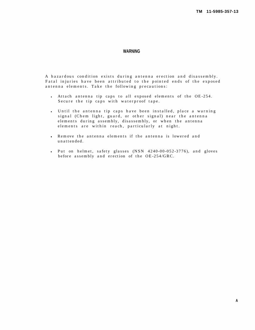
A hazardous condition exists during antenna erection and disassembly.Fatal injuries have been attributed to the pointed ends of the exposedantenna elements. Take the following precautions:
Attach antenna tip caps to all exposed elements of the OE-254.Secure the tip caps with waterproof tape.
Until the antenna tip caps have been installed, place a warningsignal (Chem light, guard, or other signal) near the antennaelements during assembly, disassembly, or when the antennaelements are within reach, particularly at night.
Remove the antenna elements if the antenna is lowered andunattended.
Put on helmet, safety glasses (NSN 4240-00-052-3776), and glovesbefore assembly and erection of the OE-254/GRC.
A
TM 11-5895-357-13
FIXED OPERATION WITH LONG RANGE ANTENNASWARNING
TELESCOPING ANTENNA
MAST
TYPICAL TOWER EXTENDED RANGE
ANTENNA
DOUBLET ANTENNA
NEVER ERECT THESE LONG RANGE ANTENNAS DIRECTLY UNDER POWER LINES.IF YOU MUST ERECT THESE LONG RANGE ANTENNAS NEAR POWERLINES, POWERLINE POLES ORTOWERS, OR BUILDINGS WITH OVERHEAD POWERLINE CONNECTIONS, NEVER PUT THE ANTENNACLOSER THAN TWO TIMES THE ANTENNA HEIGHT FROM THE BASE OF THE POWERLINE, POLE,TOWER OR BUILDINGS.
NEVER ATTEMPT TO ERECT ANY LONG RANGE ANTENNA WITHOUT A FULL TEAM.BEFORE ERECTING ANY LONG RANGE ANTENNA, INSPECT ALL THE PARTS MAKING UP THEANTENNA KIT. DO NOT ERECT THE ANTENNA IF ANY PARTS ARE MISSING OR DAMAGED.
DO AS MUCH OF THE ASSEMBLY WORK AS POSSIBLE ON THE GROUND.
WHEN ERECTING THE ANTENNA, ALLOW ONLY TEAM PERSONNEL IN THE ERECTION AREA.
MAKE SURE THAT THE AREA FOR THE ANCHORS IS FIRM. IF THE GROUND IS MARSHY OR SANDY,GET SPECIFIC INSTRUCTIONS FROM YOUR CREW CHIEF OR SUPERVISOR ON HOW TO REINFORCETHE ANCHORS.
WHEN SELECTING LOCATIONS FOR ANCHORS, AVOID TRAVELED AREAS AND ROADS. IF YOU CANNOTAVOID THESE AREAS, GET-SPECIFIC INSTRUCTIONS FROM YOUR SUPERVISOR AS TO WHAT CLEAR-ANCE YOUR GUY WIRES AND ROPES MUST HAVE OVER THE TRAVELED AREAS AND ROAD.
CLEARLY MARK ALL GUY WIRES AND ROPES WITH THE WARNING FLAGS OR SIGNS SUPPLIED BY YOURUNIT. IN AN EMERGENCY, USE STRIPS OF WHITE CLOTH AS WARNING STREAMERS.
IF YOU SUSPECT THAT POWERLINES HAVE MADE ACCIDENTAL CONTACT WITH YOUR ANTENNA, STOPOPERATING, ROPE OFF THE ANTENNA AREA, AND NOTIFY YOUR SUPERIORS.
IF THE WEATHER IN YOUR AREA CAN CAUSE ICE TO FORM ON YOUR LONG RANGE ANTENNA AND ITSGUY WIRES AND ROPES, ADD EXTRA GUYS TO SUPPORT THE SYSTEM. ROPE OFF THE AREA ANDPOST IT WITH WARNING SIGNS LIKE "BEWARE OF FALLING ICE".
DO NOT TRY TO ERECT ANY ANTENNA DURING AN ELECTRICAL STORM.
KEEP A SHARP EYE ON YOUR ANCHORS AND GUYS. CHECK THEM DAILY AND IMMEDIATELYBEFORE AND AFTER BAD WEATHER.
B
TM 11-5895-357-13
C/(D blank)
*TM 11-5985-357-13
T ECHNICAL M A N U A L HEADQUARTERSDEPARTMENT OF THE ARMY
NO. 11-5985-357-13 Washington, DC, 1 February 1991
CHAPTERSECTION
SECTION
CHAPTER
OPERATOR’S, ORGANIZATIONAL, AND
DIRECT SUPPORT MAINTENANCE MANUAL
ANTENNA GROUP OE-254/GRC
(NSN 5985-01-063-1574)
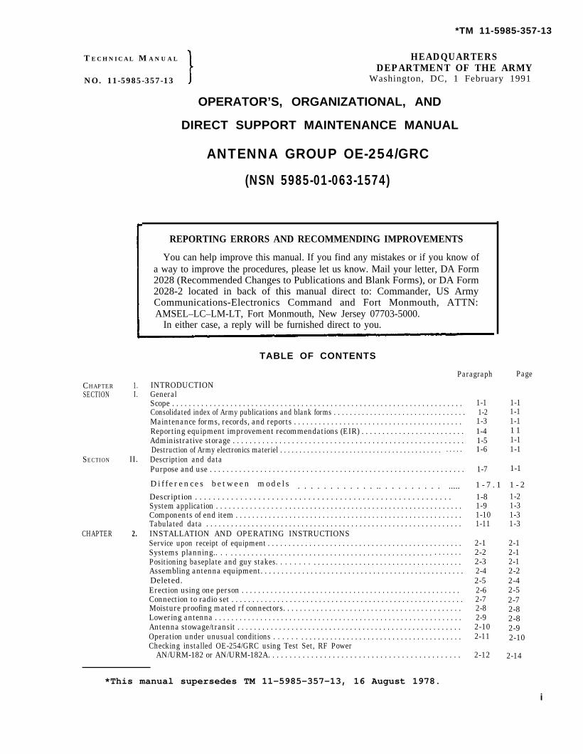
REPORTING ERRORS AND RECOMMENDING IMPROVEMENTS
You can help improve this manual. If you find any mistakes or if you know ofa way to improve the procedures, please let us know. Mail your letter, DA Form2028 (Recommended Changes to Publications and Blank Forms), or DA Form2028-2 located in back of this manual direct to: Commander, US ArmyCommunications-Electronics Command and Fort Monmouth, ATTN:AMSEL–LC–LM-LT, Fort Monmouth, New Jersey 07703-5000.
In either case, a reply will be furnished direct to you.
a. This manual describes Antenna GroupOE-254/GRC (fig. 1-1) and provides instruction forinstallation, operation, and maintenance. It includesinstructions for operation under usual and unusualconditions, cleaning and inspection of the equipment,and replacement of parts available to the repairtechnican.
b. The maintenance allocation chart appears inappendix D.
1-2. Consolidated Index of Army Publicationsand Blank Forms
Refer to the latest issue of DA Pam 25-30 to determinewhether there are new editions, changes, or additionalpublications pertaining to the equipment.
1-3. Maintenance Forms, Records, and Reports
a. Reports of Maintenance and UnsatisfactoryEquipment. Department of the Army forms andprocedures used for equipment maintenance will bethose presribed by DA Pam 738-750, as contained inMaintenance Management Update.
b. Report of Item and Packaging Discrepancies. Fillout and forward SF 364 (Report of Discrepancy (ROD))as prescribed in AR 735-11-2/DLAR 4140.55SECNAVINST 4355.18/AFR 400-54/MCO 4430.3J.
c. Transportation Discrepancy Report (TDR) (SF361). Fill out and forward Transportation DiscrepancyReport (TDR) (SF 361) as prescribed in AR 55-38/NAVSUPINST 4610.33C/AFR 75-18/MCO P4610.19D/DLAR 4500.15.
If your equipment needs improvement, let us know.Send us an EIR. You, the user, are the only one who cantell us what you don’t like about your equipment. Let usknow why you don’t like the design or performance.Put it on an SF 368 (Product Quality Deficiency Report).Mail it to: Commander, US Army Communications-Electronics Command and Fort Monmouth, ATTN:AMSEL–ED–PH, Fort Monmouth, New Jersey07703-5000. We’ll send you a reply.
1-5. Administrative Storage
Administrative storage of equipment issued to and usedby Army activities will have preventive maintenanceperformed in accordance with the PMCS charts beforestoring. The requirements apply whether the antenna isstored with an associated radio or stored alone. Whenremoving the equipment from administrative storage,the PMCS should be performed to assure operationalreadiness. Before and after storage, clean the unit(para 3-5) and paint bare metal parts (para 4-4).Disassembly and repacking of equipment for shipmentor limited storage are covered in paragraphs 2-10,6-4, and 6-5.
1-6. Destruction of Army ElectronicsMateriel
Destruction of Army Electronics Materiel to preventenemy use shall be in accordance with TM 750-244-2.
1-1
TM 11-5985-357-13
Section II. DESCRIPTION AND DATA
1-7. Purpose and Use
a. Antenna Group OE-254/GRC (fig. 1-1) is an omni-directional, biconical antenna designed for broadband op-eration without field adjustment from 30 to 88 MHz, upto 350 watts.
b. The OE-254/GRC is intended for use with the fol-lowing radios: Radio Sets AN/VRC-l2, AN/VRC-43through AN/VRC-49 (TM 11-5820-401-10-1, TM11-5820-401-10-2) AN/VRC-53, AN/VRC-64,AN/GRC-125, and AN/GRC-160 (TM 11-5820-498-12);and with the following man-pack radios: Radio SetsAN/PRC-25 (TM 11-5820-398-12) and AN/PRC-77(TM 11-5820-667-12); and with similar radios operatingin the 30— to 88— MHz band,
1-7.1 Differences Between Models
a. This manual covers two models of the OE-254/GRC, which have differences in the mast,base, and plate. The following table identi-fies these differences. All other componentsare identical.
The antenna consists of Antenna AS-3166/GRC,Mast AB-1244/GRC or Mast AB-1244B/GRC, andCable Assembly, Radio Frequency CG-1889C/U(80 ft); all parts are stowed in a transit bag.The feedcone assembly mounts the six anten-na elements and the balun assembly and pro-vides for mechanical connection to the mast byuse of an insulating extension. The balun as-sembly is connected to the radio set by CableAssembly, Radio Frequency CG-1889C/U. MastAB-1244/GRC or Mast AB-1244B/GRC is used toelevate the antenna above ground and is heldin a vertical position by eight guy ropes. The
equipment is designed for hand or vehicular transporta-tion. When disassembled, it is packed in a nylon fabricroll bag 42 inches long and 39 inches in circumference.
a. Antenna AS-3166/GRC. The AS-3166/GRC is abroadband, omnidirectional, biconical antenna. Thethree upward and three downward extended radials simu-late two cones which are electrically above ground makingthe overall antenna a balanced antenna. The extendedradials project at an angle of 30 degrees from true vertical.The nominal impedance of a biconical antenna is 200ohms requiring the use of a balun transformer to matchthis balanced impedance to the 50-ohm unbalanced (oneside grounded) output impedance of the radio to whichthe AS-3166/GRC is connected. The impedance transfor-mation is accomplished on the AS-3166/GRC through the4 to 1 balun (balanced to unbalanced) transformer attach-ed between the two cones. Radial cone angle and radiallength have been adjusted on the AS-3166/GRC to pro-vide an acceptable impedance match over the frequencyrange from 30 to 88 MHz. This feature provides a broad-band antenna that requires no adjustments in the ele-ments over the operating frequency once erected.
b. Antenna Elements. The extended radials consist of oneeach of mast sections AB-24, MS-117A and MS-116A.The mast sections are copper plated, painted tubes ofhigh-stgrength steel which can be screwed together.c. Mast. The mast consists of five lower and
five upper mast sections, a lower adapter as-sembly, an upper adapter assembly, and a mastand base assembly rising to a height ofapproximately 28 feet 3 inches (8.6 meters)(fig. 1-1). Each tubular mast section has amale and female end, which permits the sec-tions to be fitted together. The lower adapterassembly mates the lower and upper mast sec-tions into a single unit. The upper adapterassembly is the interface between the mast andthe insulating extension of the AS-3166/GRC.
d. Mast and Base Assembly AB-1244/GRC (fig. 1-2.2).This assembly consists of a short tubular supporting sec-tion attached to a stake by a yoke and clevis pin. Thelowermost mast section is placed over this tubular section.The yoke and clevis pin arrangement is supplied in twopieces and allows the mast assembly to be lowered to theground by pivoting about the stake.
1-2
TM 11-5985-357-13
Figure 1-2.1 Antenna Group OE-254/GRC, components and running spare parts,
(Updated Version).
1-3
TM 11-5985-357-13
e. Mast and Base Assembly AB-1244B/GRC (fig.1-2.3). This improved design prevents damage tothe assembly during installation. It is function-ally identical to the AB-1244/GRC mast and baseassembly but is not interchangeable with it.
f. Base Plate. The baseplate is a fabricated metal plateused to distribute the load of the mast and base assembly.The plate is fixed to the ground by the use of two drivenstakes which secure the plate from movement. The base-plate is keyed for proper orientation of the mast assembly.
g. Guy Assemblies, Guy Plates, Guy Snubbers, and GuyStakes. These items hold the mast assembly in the verticalposition (fig. 1-1).
Figure 1-2.2 Mast and base assembly AB-1244/GRC.
h. Guy Plate. A guy plate, color coded blue, is slid ontothe male end of the lower adapter assembly before it is as-sembled to the upper mast sections. A second guy plate,color coded red, is slid onto the male end of the upperadapter assembly before being mated with the insulatingextension of the AS-3166/GRC. The upper and lower guyropes attach to these plates.
i. Cable Assembly, Radio Frequency CG-1889C/U. TheCG-1889C/U is an 80-foot length of 50 ohm, solid-dielec-tric, coaxial radiofrequency cable terminated in malePlugs UG-21/U.
j. Connector Adapter TRU-2064. The TRU-5064 is re-
Figure 1-2.3 Mast and base assembly AB-1244B.
1-4
TM 11-5985-357-13
1-10. Components of End Item
quired to adapt the CG-1889C/U to radios equipped withtype BNC antenna connectors.
k. Clamp, Electrical Conductor, Strain PF-211/G. A strainrelief clamp attaches the CG-1889C/U to the upper guyplate to eliminate strain on the connector caused by theweight of the dangling cable.
l. Anticorrosion Silicone Compound. The silicone com-pound (item 2, app E) is intended for application to thethreaded areas of the mast sections, before assembly, todeter seizing with prolonged exposure to weather.
m. Electrical Tape. The tape is intended for dressing(lashing) the CG-1889C/U to the mast at points in itsdownward run, and for moisture proofing mated rf con-nectors.
n. Hammer. A 2½ pound hammer is provided for useduring installation of the mast assembly.
o. Transit Bag. The transit bag is a nylon fabric roll bagwith pockets and straps to hold the antenna componentsfor transportation in the field. An adjustable shoulderstrap is provided for easy carrying.
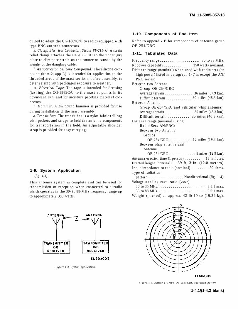
1-9. System Application(fig. 1-3)
This antenna system is complete and can be used fortransmission or reception when connected to a radiowhich operates in the 30- to 88-MHz frequency range upto approximately 350 watts.
Figure 1-3. System application.
Refer to appendix B for components of antenna groupOE-254/GRC
1-11. Tabulated Data
Frequency range . . . . . . . . . . . . . . . . . . . .. 30 to 88 MHz.Rf power capability . . . . . . . . . . . . ... 350 watts nominal.Distance range (nominal) when used with radio sets (on
high power) listed in paragraph 1- 7 b, except the AN/PRC series:
Figure 1-4. Antenna Group OE-254/GRC radiation pattern.
1-4.1/(1-4.2 blank)
TM 11-5985-357-13
Figure 1-5. Antenna AS-3166/GRC.
1-5
TM 11-5985-357-13
Figure 2-0. WARNING INSTRUCTIONS—to be followed when erecting or lowering antenna.
1-6
TM 11-5985-357-13
CHAPTER 2
INSTALLATION AND OPERATING INSTRUCTIONS
2-1. Service Upon Receipt of Equipment
a. Unpacking. Follow the procedures outlinedbelow when unpacking the equipment.
(1) Remove the staples from the end flaps of thecorrugated carton with a pry bar.
CAUTIONDo not pry into the interior of the casewith a pry bar; this may damage the equip-ment.
(2) Open the corrugated carton and remove thecontents.
(3) Place the contents on a clean, dry surface.(4) Unwrap the components by opening the four
outside and one inside securing straps of the transitbag.
b. Checking Unpacked Equipment. Inspect theequipment for damage incurred during shipment. Ifthe equipment has been damaged, refer to paragraph1-3 for applicable forms and records.
c. Inventory. Check the equipment against thepacking list, or appendix B.
2-2. Systems Planning
This antenna is omnidirectional; therefore, locatedas follows:
a. As far as possible from, and never adjacent to,high tension powerlines and telephone lines. Installa-tion shall be a distance equal to at least twice theheight of the antenna from powerlines.
WARNINGNever erect the antenna where powerlinescould possibly sag or break and come incontact with the antenna or transmissionline. See other warnings on inside frontcover.
b. In the clear-away from trees, buildings andobstructions; preferably on the highest availableland. Obstructions such as hills or manmade objectssuch as steel towers and steel/concrete structurestend to block or reduce transmission/reception in thedirection in which they are located.
c. As far as possible from other types of transmit-ting/receiving equipment; to avoid mutual couplingand interference.
d. The installation site should be free and clear ofall obstructions within a 25-foot radius (7.62 meters)of the mast and base assembly. The antenna shouldbe placed so it can be reached easily during allweather conditions. Initial assembly of the antennasystem in the horizontal plane will require anassembly area approximately 8 feet wide and 42 feetlong.
e. When selecting the antenna site, be sure that the80-foot coaxial cable will reach from the antenna tothe radio set.
f. If the antenna assembly is not to be raised to itsfull height (fig. 1-1), the lower and upper adapterassemblies must be used. For example, if theAS-3166/GRC (fig. 1-5) is to be installed after thelower guy plate (blue), the following procedures,adapted to instructions in paragraph 2-4, shallapply:
(1) The radius distance to the stakes shall be ap-proximately 25 feet maximum (7.62 meters).
(2) Assemble the upper adapter assembly to thelower adapter assembly after the lower guy plate(blue) is installed.
WARNINGDon helmet, safety glasses, and glovesbefore assembly and erection of theOE-254/GRC.
2-3. Positioning Baseplate and Guy Stakes
a. Place the baseplate, with the ribs up, where theantenna is to be erected.
b. Drive the stake of the mast and base assemblythrough the center hole of the baseplate with thehammer.
c. Drive the two pin stakes through opposite cornerholes of the baseplate.
d. Locate the position of the four guy stakeassemblies at a maximum radius of 25 feet (7.62meters) from the center of the baseplate and a 90degree angle between stakes (fig. 2-1 ). The baseplateribs should be in alignment with two opposite stake
2-1
TM 11-5985-357-13
assemblies. The guy stake positioning radius can beapproximated by using the five lower mast sections,the lower adapter assembly and three upper mast sec-tions fitted together to mark the guy stake location.
Figure 2–1. Positioning on guy stakes
e. Drive the four guy stakes at a 60-degree angleinto the earth facing away from the mast (fig. 2–2).
Figure 2–2. Driving Guy stake.
2-4. Assembling Antenna Equipment
a. Assemble five lower mast sections by in-serting the male ends into the female ends (fig.
2-2
2-3). Place the bottom section of the assembly overthe movable portion of the mast and base assembly.
Figure 2-3. Assembling mast.
b. Slide a guy plate, color coded blue, onto the maleend of the lower adapter assembly. Assemble thelower adapter assembly to the five lower mast sec-tions.
c. Assemble five upper mast sections and join themwith the six already assembled.
d. Slide a guy plate, color coded red, onto the maleend of the upper adapter assembly. Assemble the up-per adapter assembly to the mast.
e. Turn the guy plates so that one hole of each isuppermost.
f. Attach the guy hooks, color coded blue, of thefour lower guy ropes to the holes of the lower guyplate (fig, 2–4).
Figure 2-4. Attachment of guy hooks to guy plate.
g. Extend the guy ropes to the anchor assembliesand attach the free end guy loop of the guy snubber tothe anchor hooks (fig. 2-5). When attached this way,each guy rope can be pulled as taut as desired bylengthening the guy loop.
Figure 2-5. Guy attachment to ground anchor.
TM 11-5985-357-13
h. Attach the upper four guys, color coded red, tothe red guy plate and anchor assemblies in a similarmanner (g above).
i. Pull the four side guy ropes, two upper and twolower, taut and secure them (fig. 2-6). The methodfor pulling guy lines taut is as follows:
(1) Remove guy from snubber lock (fig. 2-7).(2) Pull snubber along guy in direction towards
mast (fig. 2-8).(3) Secure guy by looping guy under snubber
(fig. 2-6).j. Lay the two bottom (lower and upper) guy ropes
along one set of taut side guy ropes and adjust tothe same length. Attach the bottom guy ropes to theback guy stake (fig. 2-15).
Figure 2-6. Secure guy snubber.
Figure 2-7 Removing guy from snubber lock.
Figure 2-8. Pulling guy rope taut.
k. Erect the antenna mast using the procedures inparagraph 2-6. After the guy ropes areproperly taut, lower the antenna (para 2-9) andinstall the feedcone assembly with the antennaelements (1 below) and erect the mast again.
l. Installing Feedcone Assembly and AntennaElements.
(1) Coat the insulating extension screw threadwith anticorrosion compound (silicone) (item 2, app.E). Screw the insulating extension into the feedconestructure (fig. 2-9) and assemble to the mast.
Figure 2-9. Connecting insulating extension to feedcone assembly.
(2) Coat the screw threads on the AB-24,MS-117A, and MS-116A with anticorrosioncompound. Assemble the, antenna elements byscrewing Mast Sections AB-24, MS-117A, andMS-116A (fig. 2-10) (1 each: AB-24, MS-117A, andMS-116A in each section).
Figure 2-10. Assembling antenna elements.
(3) Attach the antenna elements to the feed- NOTEcone assembly by screwing the male ends on MS-116A into the female sockets located on the Additional weatherproofing of the an-
feedcone assembly (fig. 2-10). Install antenna tenna assembly may be made at this timetips on each of the antenna elements and secure by wiping excess anticorrosion compoundwith electrical tape (item 1, Appx. E.)
2-3
TM 11-5985-357-13
from the antenna assembly and dressingthe joints with electrical tape (item 1, appE).
(4) Unscrew the connector cap of the feedconeassembly connector and secure the cap to theconnector protective bracket by sliding the clip onthe cap under the retaining clip (if provided) until itis captivated in the slot (fig. 2-11). When securedthe cap will be captivated as shown in figure 2- 12).
(5) Connect Cable Assembly, Radio FrequencyCG-1889C/U to the feedcone assembly by screwingthe cable connector into the connector located on thefeedcone assembly.
(6) Relieve the strain of the fittings and on thecable connector by attaching the strain relief clampthrough the fifth hole of the upper guy plate andattaching it to the CG-1889C/U (fig. 2-13 and 2-14)Leave a loop in the cable to prevent strain. Ad-ditional strain relief is provided by taping the cableassembly, using electrical tape (item 1, app E) to themast at a point just below the feedcone assembly
base and at points every 5 feet from there tothe bottom of the mast (fig. 1-1).
Figure 2-13. Strain clamp open.
Figure 2-14. Strain clamp closed.2-4
TM 11-5895-357-13
2-5. Deleted.
WARNING
WATCH OUT FOR POWERLINE.Observe the warnings on theinside of the front coverand in figure 2-0.
2-6. Erection Using One Person (fig. 2-15)
Only one person is needed for erecting the OE-254; proceed as follows:
a. Follow the assembly procedures in para-graph 2-4.
b. To properly raise the mast, the length ofthe pulling guy ropes is critical. Walk themover to either of the side guy stakes. Locatepoint on the upper pulling guy rope where itmeets the guy stake. The lower pulling guyshould then be approximately one foot shorterthan the upper pulling guy. Simply tie a slipknot with the upper and lower pulling guys atthat point and return to the base with theknot in hand.
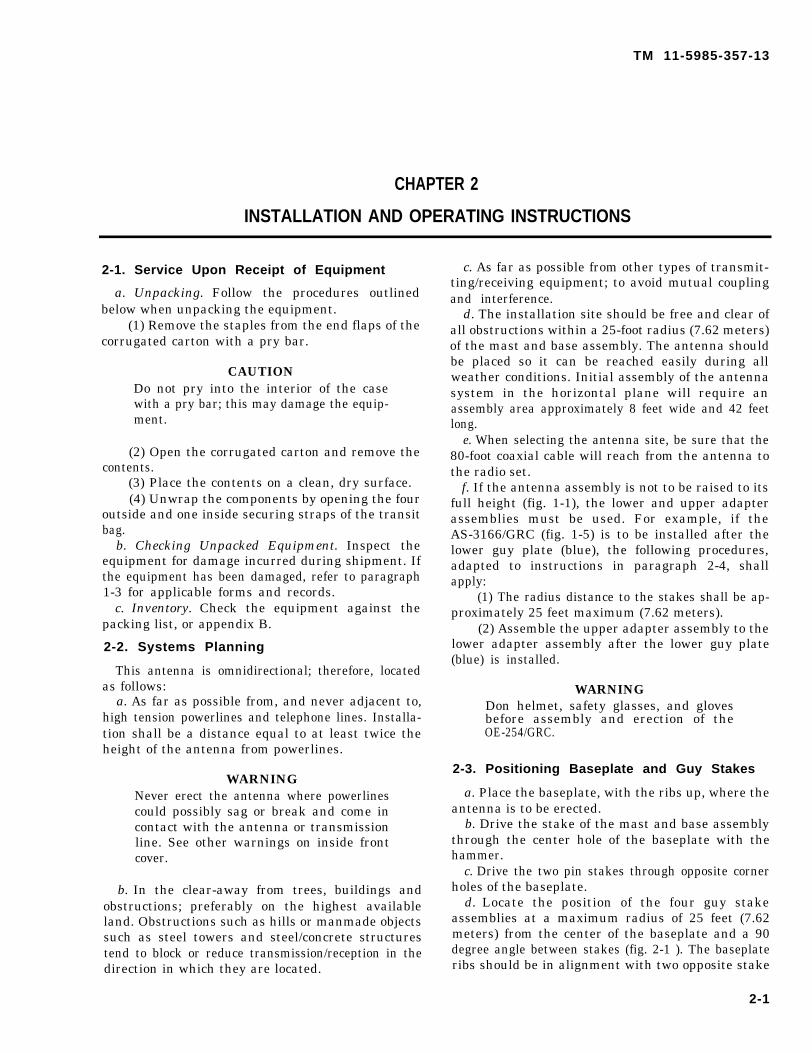
c . The mast is ready to erect. Grasp theslip knot firmly in both hands (lower guy ropewill be slack). With both arms extended for-ward at chest level, pull the mast off theground (using mainly back and leg strength).If available, raise the mast head off theground up to four feet by using a gin pole,box, or concrete block (fig. 2-16, sheets 1and 2). Walk backwards to the rear guy stakeuntil the mast is fully erect. Do not pull thelower pulling guy because it will automatical-ly tighten during erection. The large initialbow in the mast is normal.
d. Now that the mast is fully erect, removethe slip knot, attach the pulling guys to therear guy stake, and adjust the tension in allof the guys appropriately. Check vertical po-sitioning by comparing the mast with a build-ing, pole, etc.
NOTE
Leave a slight slack in each guyrope to allow for expansion andcontraction of the mast and guyropes. Check the tautness in themorning and during the day. Ex-perience with the temperatureconditions of the area will de-termine how taut the guy ropesshould be.
e. To lower the mast, approximate the pull-ing points on the lowering guys and tie theminto a slip knot.
CAUTION
Maintain firm control of thelowering guys to prevent themast and feedcone from crashingto the ground.
With both arms extended forward at chestlevel, lower the antenna gently to the ground.
Figure 2-15. Erecting Antenna Group OE-254/GRC using one person.
2-5
Figure 2-16.
TM
11-5985-357-13
2-6
Figure 2-16.
TM
11-5985-357-13
2-6.1/(2-6.2 blan
k)
TM 11-5985-357-13
2-7. Connection to Radio Set(fig. 2-17)
CAUTION
Make sure the radio set is turned off whilemaking connections from the radio to theOE-254/GRC.
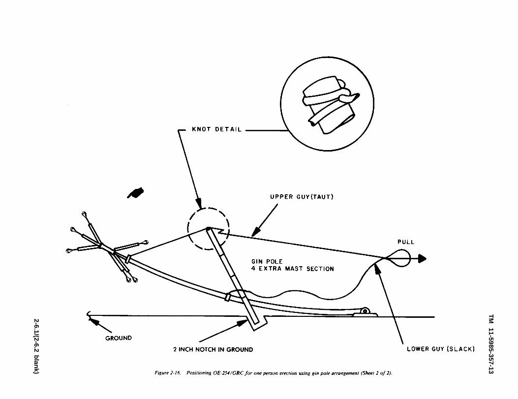
a. Connect the CG-1889C/U connector to theconnector of the radio set. Use Connector AdapterTRU-2064 as the interface between the CG-1889C/Uconnector and radios equipped with a type BNCantenna connector.
b. To protect the cable from vehicles and personswalking in the area, lay boards on the ground on bothsides of the CG-1889C/U. The boards should be thickerthan the cable.
2-7
TM 11-5985-357-13
Figure 2-17. Connections of CC-1889C/U to AS-3166/GRC and radio.
2-8. Moistureproofing Mated Rf Connectors
a. A method for moistureproofing mated rf connectorsis to use the electrical tape (item 1 app E) over the con-nector junction. As in case of anticorrosion protection(para 2-4 l) d, taping should be renewed periodically. Ifboth the silicone grease and taping are used, remove ex-cess grease from the outside of the connector assembly
before tap-ing the assembly. Use taping for permanent or semiper-manent outdoor installation where uncoupling is not anti-cipated more frequently than approximately once eachthree months or longer.
b. Tape coaxial cable junctions as follows:(1) Assembly connectors to the cable.(2) Tightly apply electrical tape on cable immediate-
ly behind the connector to provide a smooth contour be-tween cable and connector (fig. 2-18).
(3) Tightly wrap several layers of tape with a 50 per-cent overlap over the built-up junction. Use a minimumof four layers. The completely taped covering should ex-tend beyond the connector for a distance equal to 8 to 12times the diameter of the cable and have a smooth andsymmetrical contour (fig. 2-19).
Figure. 2-18. Preparing mated connectors for weatherproofing.
Figure 2-19. Weatherproofing mated connectors.
2 - 8
TM 11-5985-357-13
2-9. Lowering Antenna
WARNING
● BEFORE LOWERING THE AN-TENNA, READ THE “LONGRANGE ANTENNA WARNING” INTHE FRONT OF THIS MANUAL.● IF THERE ARE POWER LINESNEARBY, LOWER THE ANTENNAIN THE DIRECTION OPPOSITETHE POWER LINES.● CLEAR THE AREA OF PERSON-NEL, EQUIPMENT, AND VEHI-CLES BEFORE STARTING TOLOWER THE ANTENNA.
a. Obtain a support to keep the radial elements off theground as the mast is lowered.
b. To lower the antenna, remove one set of guy ropes(upper and lower) which are aligned with the pivot clevison the mast base section (fig. 2-20, 2-20.1) and lower theantenna to the ground by letting it pivot about the mastand base assembly.
CAUTIONAllow only a slight bow in the mast dur-ing the lowering operation.
The OE-254/GRC should be disassembled and stowed inthe transit bag, when the equipment is in transit orstorage. Pack the equipment in the transit bag as follows:
a. Secure items in the roll bag as shown infigure 2-21 or 2-21.1. Fold the stake portion ofof mast and base assembly of the AB-1244/GRC(fig. 2-21.1) to a 90 degree angle in order tofit within the transit bag.
b. Fold the secured mast sections AB-24 onto mast sec-tions MS-117A.
c. Fold the roll bag section with secured feedcone
assembly onto the mast sections placing the feedcone as-sembly in the middle of the transmission line.
d. Fold upper and lower edge of bag toward center.e. Fold bag “A” over upper and lower bag edges so
that taped sides are running top to bottom on the bag.Run inner strap through slots “A” from inside to outside,and secure.
f. Fold side “A” over bag by overlapping with side“ A ” .
g. Run two end straps through slots “B” from insideto outside, and secure.
h. Secure center straps.
2-10.1/(2-10.2 blank)
TM 11-5985-357-13
Figure 2-22. Typical substitute ground anchors
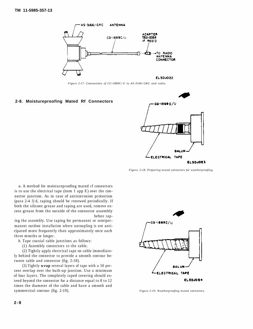
d. Installing OE-254/GRC on M577 CommandPost (fig. 2-24).
WARNINGBEFORE I N S T A L L I N G THEOE-254/GRC ON AN M577 COMMANDPOST, OBSERVE THE FOLLOWING:1. TURN OFF THE RADIO UNTILTHE OE-254/GRC IS INSTALLED.2 . W A T C H O U T F O R P O W E RLINES!!!!SEE THE WARNING IN FIGURE 2-0.ALSO, OBSERVE THE WARNINGI N S T R U C T I O N S O N A N T E N N AERECTION IN THE FRONT OF THISMANUAL.
The OE-254/GRC can be installed on the top of theM577 command post (TM 9-2300-257-10) and
connected to the radio inside the vehicle. A pair ofbrackets is provided on the top of the M577 to holdthe OE-254/GRC upright.
(1) Assemble the antenna mast as shown infigure 2-23. Only three guy ropes are required. Tapethe CG-1889C/U once or twice to the mast.
NOTEThe asembled mast can stand upright inthe M577 brackets without being guyed.The guys are left tied and stored at thebottom of the mast. If winds of over 10miles an hour are experienced, attach theguys to equidistant points on the top ofthe vehicle where “TO ANCHOR” isshown in figures 2-6, 2-7, and 2-8.
(2) Raise the assembled mast and insert the
2-11
TM 11-5985-357-13
bottom section into the brackets on the top of theM577 (fig. 2-24).
(3) Run the CG-1889C/U through the driver’shatch, coil up the extra cable length, and attach thecable connector to the radio antenna connector (fig.2-17).
WARNINGDANGEROUS VOLTAGES EXIST ON
THE RADIATING ELEMENTSWHEN THE RADIO IS TRANS-MITTING!!!AFTER THE ANTENNA IS IN-STALLED, NEVER TOUCH THEANTENNA ELEMENTS–YOUNEVER KNOW EHEN SOMEONE ISTRANSMITTING ON THE RADIO.
Figure 2-23. Assembling OE-254/GRC for use on M577 command post.
2-12
2-11. Operation Under Unusual Conditions
a. The AS-3166/GRC can be installed on utility polesand buildings by using adjustable automotive hose clampsto secure to other poles.
CAUTION
Always use the 30 inch insulating mastsection (fig. 2-9) with this antenna.
b. Camouflage Pattern Painting. Consult Training Circu-lar (TC) 5-200, Camouflage Pattern Painting for methodand application of camouflaging military equipment.
c. Soil Problems. It is difficult to anchor an antenna mastin loose sand and soft clay soil. Stakes driven into sand
TM 11-5985-357-13
and soft clay are easily loosened and pulled out by windsof moderate velocities. Keep the antenna mast guys even-ly taut at all times; but allow for expansion/contraction(para 2-5 b). If stakes driven into poor soil do not hold,some means of anchoring the stake will have to be used. Asuitable weight such as a large rock or tree should be plac-ed on top of the stake to anchor it. If in the field and noother expedient is available, use heavy tools or equipmentto anchor the stakes. Often it is practical to use a largescrew anchor (C, fig. 2-22) or preferably a dead-man an-chor (A, fig. 2-22) instead of the stake to secure the guywires of the antenna mast. A rock anchor (B, fig. 2-22)may be required for use where rock extends to the surface.
2-13
Figure 2-24. OE-254/GRC Installed on top of M577 Command Post.
TM 11-5985-357-13
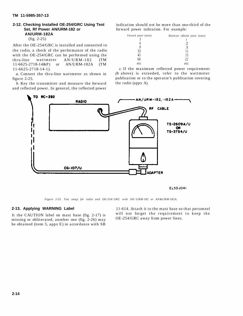
2-12. Checking Installed OE-254/GRC Using TestSet, Rf Power AN/URM-182 orAN/URM-182A
(fig. 2-25)
After the OE-254/GRC is installed and connected tothe radio, a check of the performance of the radiowith the OE-254/GRC can be performed using thethru-line wattmeter AN/URM-182 (TM11-6625-2718-14&P) or AN/URM-182A (TM11-6625-2718-14-1).
a. Connect the thru-line wattmeter as shown infigure 2-25.
b. Key the transmitter and measure the forwardand reflected power. In general, the reflected power
indication should not be more than one-third of theforward power indication. For example:
Forward power (watts) Maximum reflected power (watts)3 16 29 3
33 1145 1566 22etc etc
c. If the maximum reflected power requirement(b above) is exceeded, refer to the wattmeterpublication or to the operator’s publication coveringthe radio (appx A).
Figure 2-25. Test setup for radio and OE-254/GRC with AN/URM-182 or AN&URM-182A.
2-13. Applying WARNING Label 11-614. Attach it to the mast base so that personnel
It the CAUTION label on mast base (fig. 2-17) is will not forget the requirement to keep the
missing or obliterated, another one (fig. 2-26) may OE-254/GRC away from power lines.be obtained (item 5, appx E) in accordance with SB
2-14
TM 11-5985-357-13
Figure 2-26. WARNING label.
2-15/(2-16 blank)
TM 11-5985-357-13
CHAPTER 3
OPERATOR/CREW MAINTENANCE
WARNINGDangerous rf voltages exist at AS-3166/GRC elements and connectors. Personnelshould be familiar with the warnings and safety instructions given in the front of themanual before attempting maintenance.
3-1. Scope of Operator’s Maintenance
Following is a list of maintenance duties normallyperformed by the OE-254/GRC operator. Theseprocedures do not require special tools or test equip-ment.
a. Preventive maintenance checks and serviceschart (table 3-1).
b. Cleaning (para 3-5).
3-2. Materials Required
a. Trichlorotriflouroethane (item 3, appx E).b. Cleaning cloth.
3-3. Operator/Crew Preventive Maintenance
Preventive maintenance is the systematic care, ser-vicing, and inspection of equipment to prevent the oc-currence of trouble, reduce downtime, and assurethat the equipment is operational.
a. Systematic Care. The procedures given in table3-1 cover routine, systematic care and cleaning es-sential to proper upkeep and operation of the equip-ment.
b. Preventive Maintenance Checks and Services.The preventive maintenance checks and serviceschart (table 3-1) outlines functions to be performeddaily. These checks and services are to maintainArmy electronic equipment in a combat-serviceablecondition; that is, in good general (physical) conditionand in good operating condition. To assist operatorsin maintaining combat serviceability, the chart in-dicates when to check, how to check, and the normalconditions. The for readiness reporting, equipment isnot ready/available if column lists the criteria when theOE-254/GRC is classified as not ready for its primarymission. If the defect cannot be remedied by theoperator, higher category maintenance or repair isrequired. Records and reports of these checks andservices must be made in accordance with therequirements set forth in DA Pam 738-750.
3-4. Preventive Maintenance Checks and Ser-vices Periods
Preventive maintenance checks and services (PMCS)of the OE-254/GRC are required on a daily/weeklybasis. Table 3-1 specifies checks and services thatmust be accomplished under the conditions listedbelow.
a. During. Be sure to perform during (D)procedures each day the antenna is installed.
b. Weekly Procedure. If the equipment was notchecked during the week, perform the D PMCStogether with the weekly (W) PMCS.
c. If Your Radio Equipment Fails to Operate.Troubleshoot the radio system as outlined in theapplicable technical manual for the radio system (appA). If you are unable to clear the trouble, report thefailure using the proper form (DA Pam 738-750).
NOTES
Routine checks are not listed as PMCS;such as: cleaning (para 3-5); checking forfrayed cables; stowing items not in use;covering unused receptacles; checking forloose nuts and bolts. These are things thatshould be done anytime you see they mustbe done.The Item No. in table 3-1 shall be used asa source of item numbers for the TMnumber column on DA Form 2404 (Equip-ment Inspection and MaintenanceWorksheet) in recording the results of thePMCS.If the equipment must be kept in constantoperation, check and service only thoseitems that can be checked and servicedwithout disturbing operation. Make com-plete checks and services when the equip-ment can be shut down.
3-1
TM 11-5985-357-13
Table 3-1. Operator’s Preventive Maintenance Checks and Services (PMCS)
Within the designated interval, these checks are to be performed in the order listed.
B - B e f o r e D-Dur ing A -After W - W e e k l y
ItemNo.
1
2
3
4
5
6
Interval
D wItem to beinspected
Guy Assemblies
CG-1889C/U
Radio Communica-tion
Guy Stakes
Baseplate
Strain Clamp
Procedure
Check and adjust, as necessary, the taut-ness of the guy assemblies. The mastshould not be bowed; check straightnessby comparing with a building, pole, etc.
NOTEExperience should tell how taut to set the guyassemblies to allow for expansion and con-traction of the mast during changes of hotand cold temperatures.
Check to see that the cable lying on theground is undamaged and, if required forarea traffic condition, is protected byboards (para 2-7 b).
Check communication function of associatedradio.
Check the guy stakes for looseness. Hammerthem in or reposition them if soil condi-tions are better in another spot.
Inspect the baseplate stakes for security inthe ground. Hammer them in if necessary.
Look to see that the CG-1889C/U is beingheld up by the strain clamp. Fix it if neces-sary (fig. 2-13 and 2-14).
For readiness reporting, equipment is notready/available if:
Associated radio communication fails be-cause of OE-254/GRC.
3-5. Cleaning
a. Remove dust and loose dirt using water andcloth or brush.
b. Remove grease, fungus, and ground-in dirtwith a dampened cloth.
c. Clean the guy ropes by washing them; allow thewashed items to dry thoroughly.
3-2
TM 11-5985-357-13
CHAPTER 4
ORGANIZATIONAL MAINTENANCE
WARNINGDangerous voltages exist in the CG-1889C/U, the feedcone assembly and theradiating elements. Therefore, never work on or touch these parts until theCG-1889 C/U is disconnected from the radio.
4-1. Scope of Organizational Maintenance
Organizational maintenance of the OE-254/GRCconsists of the following:
a Preventive maintenance (para 4-3 and table4-1).
b. Touchup painting (para 4-4).c. Troubleshooting (para 4-6).
4-2. Teat Equipment, Tools and MaterialsRequired
Organizational repair parts are listed in TM11-5985-357-23P
a. Test Equipment. Multimeter AN/URM-105 isthe only test equipment required.
b. Tools. Tool Kit, Electronic EquipmentTK-101/G contains all the tools required.
c. Materials.
Paint, Alkyd, Camouflage, Forest Green perMIL-E-52798 (item 4, appx E).
4-3. Organizational Preventive MaintenanceChecks and services
Preventive maintenance is the systematic care,inspection, and servicing of equipment to maintainit in serviceable condition, prevent breakdowns, andassure maximum operational capability.Organizational preventive maintenance checks andservices (PMCS) are performed quarterly (table 4-1).
a. Quarterly PMCS will be scheduled in ac-cordance with procedures specified in DA Pam 738-750.
b. The Item No. in table 4-1 shall be used as asource of item numbers for the TM number columnon DA Form 2404 (Equipment Inspection andMaintenance Worksheet) in recording the results ofthe PMCS.
c. If the equipment fails to meet the criteria in theprocedure scolumn of table 4-1, report the failure inaccordance with the procedures specified in DA Pam738-750.
d. If the equipment must be kept in constantoperation, check and service only those items thatcan be done without disturbing operation. Make the
complete checks and services when the equipmentcan be shutdown.
e. Routine checks are not listed in the PMCStable; such as cleaning (para 3-5), dusting, washing,checking for frayed cables; stowing items not in use;covering unused receptacles; and checking for looseguys, stakes, and cable. These are things thatshould be done anytime you see they must be done.
4-4. Touchup Painting
Antenna Group OE-254/GRC equipment thefinish of which has been badly scarred or damagedmay be cleaned and repainted using the followingprocedure.
a. Lightly sand scarred equipment surfaces with#00 or #000 grade sandpaper and clean the bare metal
b. Brush two coats of paint (Enamel, Alkyd,Camouflage, color Forest Green, per MIL-E-52798)(item 4, appx E) on the metal.
NOTERefer to the applicable cleaning andrefinishing practices specified in SB11-573 and TB 43-0118.
ProcedureCheck for and have repaired or adjustedas necessary
All components required to make theOE-254/GRC operational are on hand(app B) or are available.
TM 11-5985-357-13is on hand with Iatest changes; see DAPam 25-30 for current publication listing.
Check DA Pam 25-30 to see if any modi-fication work orders (MWO’s) arelisted for the OE-254/GRC or its com-ponents. All URGENT MWO’s must beapplied immediately; all NORMALMWO's must be scheduled.
Remove rust, corrosion, and fungus; spot-paint bare metal spots (para 4-4).
Remove old and install new electrical tape(item 1, app E) on connections (fig. 2-18and 2-19).
Remove old and install new anticorrosioncompound (item 2, app E) on threadedareas of the mast sections and insulat-ing extension.
Perform the applicable organizational maintenanceprocedure using the technical manual for the radioset with which the OE-254/GRC is used. If theO E - 2 5 4 / G R C i s d e f e c t i v e , p e r f o r m t h etroubleshooting operations given in paragraph 4-6.If the corrective measures given in paragraph 4-6 donot clear the trouble, higher category maintenance isrequired.
4-6. Organizational Troubleshooting
The electrical troubles that occur in the OE-254/GRC
are open circuits, short circuits, and poor connections.These troubles can be isolated by making continuitychecks, using Multimeter AN/URM-105. Theprocedures are listed below.
a. Place the antenna base on an insulated surface.
b. Check the feedcone assembly (fig. 6-2) asfollows:
(1) Check the continuity between the radial ele-ment sockets and the Connector UG-680B/U centerpin on the feedcone assembly using a lowresistance range on the ohmmeter, The resistanceshould be near zero.
(2) Check the continuity between theUG-680B/U connector center pin and outer conduc-tor using a low resistance range on the ohmmeter.The resistance should be near zero,
(3) If required readings in (1) and (2) above arenot obtained, replace the feedcone assembly.
c. Check the CG-1889C/U as follows:(1) Check the continuity of the coaxial cable
center conductor, using a low resistance range of theohmmeter. The resistance should be near zero. Anopen circuit is indicated by a resistance reading of in-finity.
(2) Check the coaxial cable for a short circuitbetween the wire braid and the center conductor, us-ing the highest resistance range of the ohmmeter. Theresistance should be nearly infinity if no short is pres-ent.
(3) If required readings are not obtained in (1) or(2) above, replace the CG-1889C/U.
4-7. Repairs
Repairs on the OE–254/GRC consist mainly ofreplacing the defective component (fig. 1-2) withparts authorized organizational maintenance; see TM11-5985-357-23P for parts l isting.
4-2
TM 11-5985-357-13
CHAPTER 5
FUNCTIONING OF EQUIPMENT
5-1. General(fig. 1-1)
Antenna Group OE-254/GRC consists primarilyof Antenna AS-3166/GRC mounted on Mast AB-1244/GRC or Mast AB-1244B/GRC. Cable Assem-bly, Radio Frequency CG-1889C/U (80 ft) isconnected between the feedcone assembly ofthe AS-3166/GRC and the associated radio.The cable and the AS-3166/GRC provide radio-frequency communication in the 30- to 88-MHzrange, up to 350 watts (nominal). The balunassembly in the feedcone assembly (fig. 5-1)provides impedance match between the imped-ances of the radio and the biconical antennaelements (para 5-2).
5-2. Balun Assembly Function
The balun assembly is a 4:1 impedance transformerthat matches to nominal 200 ohms impedance at thebiconical antenna terminals to the unbalanced 50 ohmtransmission line. The transformer consists of twobifilar windings on a ferrite toroid core as shown infigure 5–1. The two windings are connected in seriesto provide an autotransformer with the junction ofthe black and white leads providing the ground side ofthe 50-ohm impedance. The capacitor across the lowimpedance side optimizes the 50 ohms impedanceacross the 30- to 88 MHz frequency range.
Figure 5-1. Balun assembly diagram.
5-1/(5-2 blank)
TM 11-5985-357-13
CHAPTER 6
DIRECT SUPPORT MAINTENANCE INSTRUCTIONS
6-1. Scope of Direct Support Maintenance
Direct support maintenance includes those in a and bbelow in addition to the duties prescribed fororganizational maintenance (chap 4). Repair parts arelisted in TM 11–5985–357-23P.
a. Repair of the feedcone assembly includingreplacement of the feedcone subassembly orUG-680/U and the repair of broken lead wires.
b. Repair of Cable Assembly, Radio FrequencyCG-1889C/U (fig. 6-7).
6-2. Tools, Test Equipment, and Materials Re-quired
a. Tools. Tool Kit,100/G.
b. Test Equipment.
c. Materials. Seematerials.
Electronic Equipment TK–
Multimeter TS–352B/U.
appendix E for available
6-3. Direct Support Troubleshooting
a. Feedcone Subassembly (fig. 6-2 and 6–3).(1) Visual inspection.
(a) Inspect the six radiating element femalesockets for evidence of an interference fit when matedwith an MS-116A antenna element.
(b) Inspect the Lexan insulator assembly andadhesive joint for cracks or evidence of deterioration.
(c) Inspect the four helical coils on the Lexaninsulator for stripping or physical deterioration.
(d) Inspect the three helical coils on the upperand lower cone castings for stripping or physicaldeterioration.
(e) Clean out the weep holes (fig. 6–2).(2) Continuity check. Place the feedcone sub-
assembly on an insulated surface. Check the continui-ty between the radial element sockets and theassociated #4 or #6 terminal using a low resistancerange on the ohmmeter (fig. 6–3). The resistanceshould be near zero.
(3) Replacement. Replace the feedcone sub-assembly if the unit fails any check made in (1) or (2)above.
b. Balun Assembly (fig. 6-1).(1) Visual inspection.
(a) Inspect the Lexan/balun housing for cracksor evidence of deterioration. Replace the balun hous-ing if unit fails inspection.
(b) Inspect the UG-680/U for damage to theconnector threads or center pin. Replace theUG-680/U following the disassembly procedure ofparagraph 6-5 a if connector fails inspection.
(c) Inspect the balun subassembly for brokenwire leads or poor solder joints. Repair or replace wireleads and solder joints if unit fails inspection.
(2) Continuity Check. Disassemble unit if re-quired, using the disassembly procedure of paragraph6-5 a. Check the continuity between the shell andcenter conductor of the UG–680/U connector andbetween the #4 terminal wire lead (white) and #6 ter-minal wire lead (black) (fig. 6-1) using a lowresistance range on the ohmmeter. Resistancereadings should be near zero indicating direct con-
tinuity. Repair or replace the UG-680/U connectoror balun subassembly if unit fails the test.
c. CG—1889C/U.(1) Check the continuity of the coaxial cable
center conductor using a low resistance range of theohmmeter. The resistance should be near zero. Anopen circuit is indicated by a resistance reading of in-finity.
(2) Check the coaxial cable for a short circuitbetween the wire braid and the center conductor, us-ing the highest resistance range of the ohmmeter. Theresistance should be nearly infinite if no short is pres-ent.
(3) If required readings are not obtained in (1) or(2) above, repair the CG-1889C/U by replacing thecable or by shortening the cable by severing a defec-tive end and replacing the connectors per cablingprocedure of figure 6-7. The cable should be aminimum 50 feet in length.
(4) Check the continuity between the connectorcenter pin and outer conductor using a low resistancerange on the ohmmeter, The resistance should bezero. Repair or replace connector per cabling
6-3
TM 11-5985-357-13
procedure of figure 6-7 if required reading is not ob-tained.
6-4. Feedcone Disassembly and Assembly Pro-cedures
a. Removal of Balun Housing Assembly.(1) Remove the four screws that hold the balun
housing to the feedcone subassembly (fig. 6–2).(2) Separate the balun housing from the feed-
cone assembly exposing the black and white wireleads connecting the balun to the feedcone sub-assembly (fig. 6-3).
(3) Remove the two screws that secure the #4(white) and #6 (black) wire lead terminal to the feed-cone structure (fig. 6-3). The balun assembly is nowdetached from the feedcone subassembly.
b. Assembling the Balun Housing Assembly.(1) Align balun gasket to the feedcone sub-
assembly (fig. 6-3).(2) Align the balun assembly with the feedcone
subassembly (fig. 6-3).(3) Screw the two screws that secure the #4
(white) and #6 (black) wire lead terminals to the feed-cone structure (fig. 6–3).
(4) Insert the four screws through the holes inthe balun housing and screw into the feedcone sub-assembly (fig. 6-2).
6-5. Balun Disassembly and Assembly Pro-cedures
a. Disassembly (fig. 6-4 and 6-5)(1) Unsolder the white lead from the center pin
of the UG—680/U connector and the black lead fromthe connector ground lug.
(2) Remove the balun subassembly from thebalun housing.
(3) Remove the connector retaining nut using asocket or end wrench.
(4) Repair or replace defective parts.
b. Assembly (fig. 6-4, 6-5 and 6-6).(1) Assemble the UG-680/U connector to the
balun housing with the connector protection bracketassembly, gasket connector, washer, lockwasher andground lug (fig. 6-6).
(2) Insert balun subassembly (fig. 6-5) andresolder white lead to the center pin of theUG–680/U connector and the black lead to the con-nector ground (fig. 6-4),
6-6. Final Assembly Inspection
The electrical troubles that occur in the AS-3166/GRC are open circuits, short circuits, and poorconnections. These troubles can be isolated by makingcontinuity checks, using Multimeter TS–352B/U.The procedures are listed below.
a. Place the antenna base on an insulated surface.b. Check the continuity between the radial element
sockets and the UG-680/U connector pin on the feed-cone assembly (fig. 6-2) using a low resistance rangeon the ohmmeter. The resistance should be near zero.
c. Check the continuity between the UG–680/Uconnector center pin and outer conductor using a lowresistance range on the ohmmeter. The resistanceshould be zero.d. Units that pass inspection may now be placed inservice.
Figure 6-4. Unsoldering wire leads.
6 - 4
TM 11-5985-357-13
Figure 6-5. Removing balun subassembly.
Figure 6-6. Assembling UG-680/U to balun assembly.
Consolidated Index of Army Publications and Blank Forms.The Army Maintenance Management System (TAMMS).Painting and Preserving Supplies Available for Field Use for Electronics
Command Equipment.Caution Notice for Antenna Bases, Towers and Other Mast Structures.Field Instructions for Painting and Preserving Communications-Electronics
Equipment.Operator’s Manual: Carrier, Personnel: Full Tracked, Armored, M113A1
Operator’s and Organizational Maintenance Manual, Including Repair Partsand Special Tools List: Radio Set AN/PRC-25 (NSN 5820-00-857-0759)(Including Receiver-Transmitter, Radio RT-505/PRC-25) (5820-00-857-0934).
Operator’s Manual: Radio Sets AN/VRC-12 (NSN 5820-00-223-7412),AN/VRC-43 (5820-00-223-7415), AN/VRC-44 (5820-00-223-7417), AN/VRC-45(5820-00-223-7418), AN/VRC-46 (5820-00-223-7433), AN/VRC-47(5820-00-223-7434), AN/VRC-48 (5820-00-223-7435), and AN/VRC-49(5820-00-223-7437) (Used Without an Intercom System).
Operator’s Manual: Radio Sets AN/VRC-12 (NSN 5820-00-223-7412),AN/VRC-43 (5820-00-223-7415), AN/VRC-44 (5820-00-223-7417),AN/VRC-45 (5820-00-223-7418), AN/VRC-46 (5820-00-223-7433),AN/VRC-47 (5820-00-223-7434), AN/VRC-48 (5820-00-223-7435),and AN/VRC-49 (5820-00-223-7437) (Used With an Intercom System).
Organizational Maintenance for Radio Sets AN/VRC-12(NSN 5820-00-223-7412), AN/VRC-43 (5820-00-223-7415), AN/VRC-44(5820-00-223-7417), AN/VRC-45 (5820-00-233-7418), AN/VRC-46(5820-00-223-7433), AN/VRC-47 (5820-00-223-7434), AN/VRC-48(5820-00-223-7435), and AN/VRC-49 (5820-00-223-7437) (UsedWithout an Intercom System).
Organizational Maintenance for Radio Sets AN/VRC-12(NSN 5820-00-223-7412), AN/VRC-43 (5820-00-223-7415), AN/VRC-44(5820-00-223-7417), AN/VRC-45 (5820-00-233-7418), AN/VRC-46(5820-00-223-7433), AN/VRC-47 (5820-00-223-7434), AN/VRC-48(5820-00-223-7435), and AN/VRC-49 (5820-00-223-7437) (UsedWith an Intercom System).
Operator’s and Organizational Maintenance Manual: Radio SetsAN/VRC-53 (NSN 5820-00-223-7467), AN/VRC-64 (5820-00-223-7475)AN/GRC-125 (5820-00-223-7411) and AN/GRC-160 (5820-00-223-7473),and Amplifier-Power Supply Groups OA-3633/GRC andOA-3633A/GRC (5820-00-973-3383).
Operator’s and Organizational Maintenance Manual, Radio SetAN/PRC-77 (NSN 5820-00-930-3724) (Including Receiver-Transmitter,Radio RT-841/PRC-77) (5820-00-930-3725).
A-1
TM 11-5985-357-13
TM 11-5985-357-23P Organizational and Direct Support Maintenance Repair Parts and SpecialTools List, Antenna Group OE-254/GRC (NSN 5985-01-063-1574).
TM 11-6625-203-12 Operator’s and Organizational Maintenance: Multimeter, AN/URM-105and AN/URM-105C, Including Multimeter ME-77/U and ME-77C/U.
TM 11-6625-366-10 Operator’s Manual for Multimeter TS-352B/U (NSN 6625-00-553-0142).TM 11-6625-2718-14-1 Operator’s, Organizational, Direct Support and General Support
Maintenance Manual: Test Set, Radio Frequency, PowerAN/URM-182A (NSN 6625-01-062-3599).
TM 11-6625-2718-14&P Operator’s, Organizational, Direct Support and General SupportMaintenance Manual Including Repair Parts and Special ToolsList: Test Set, Radio Frequency, Power AN/URM-182(NSN 6625-00-148-9371).
TM 750-244-2 Procedures for Destruction of Electronics Materiel to Prevent EnemyUse (Electronics Command).
A-2 Change 3
TM 11-5895-357-13
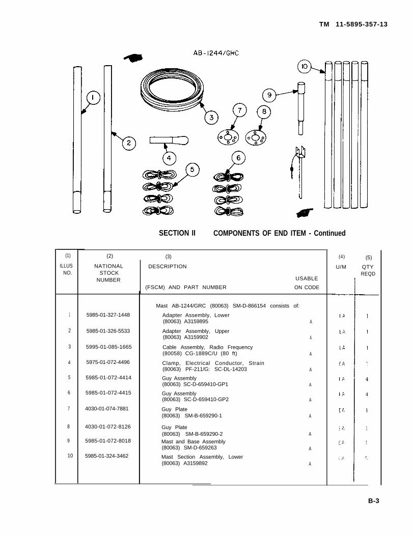
APPENDIX BCOMPONENTS OF END ITEM LIST
Section I. INTRODUCTION
B-1. Scope
This appendix lists integral components of and basic issueitems for the OE-254/GRC to help you inventory itemsrequired for safe and efficient operation.
B-2. General
This Components of End Item List is divided into thefollowing sections:
a. Section II. Integral Components of the End Item. Theseitems, when assembled, comprise the OE-254/GRC andmust accompany it whenever it is transferred or turnedin. The illustrations will help you identify these items.
b. Section III. Basic Issue Items. These are the minimumessential items requirted to place the OE-254/GRC inoperation, to operate it, and to perform emergencyrepairs. Although shipped separately packed they mustaccompany the OE-254/GRC during operation andwhenever it is transferred between accountable officers.The illustrations will assist you with hard-to-identifyitems. This manual is your authority to requisitionreplacement BII, based on TOE/MTOE authorization ofthe end item.
B-3. Explanation of Columns
a. Illustration. This column is divided as follows:(1) Figure Number. Indicates the figure number of the
illustration on which the item is shown.(2) Item number. The number used to identify item
called out in the illustration.b. National Stock Number. Indicates the National stock
number assigned to the item and which will be used for re-quisitioning.
c. Part Number. Indicates the primary number used bythe manufacturer, which controls the design and charac-teristics of the item by means of its engineering drawings,specifications, standards, and inspection requirements toidentify an item or range of items. Following the partnumber, the Federal Supply Code for Manufacturers(FSCM) is shown in parentheses.
d. Description. Indicates the Federal item name and, ifrequired, a minimum description to identify the item.
e. Location., The physical location of each item listed isgiven in this column. The lists are designed to inventoryall items in one area of the major item before moving onto an adjacent area.
f. Usable on Code “USABLE ON” codes are includedto help you identify which component items are used onthe different models. Identification of the codes used inthese lists are:
Code Used on
A OE-254/GRC with AB-1244/GRCB OE-254/GRC with AB-1244B/GRC
g. Quantity Required (Qty Reqd). This column lists thequantity of each item required for a complete major item.
h. Quantity. This column is left blank for use during aninventory. Under the Rcvd column, list the quantity youactually receive on your major item. The Date columnsare for your use when you inventory the major item at alater date; such as for shipment to another site.
11 5985-01-324-3463 Mast Section Assembly, Upper EA 5(80063) A3159899 B
12 Pla te EA 1(80063) A3002872 B
13 4030-01-072-8017 Stake EA 2(80063) SC-B-729924 B
14 5985-01-073-6103 Stake Assembly EA 4(80063) SM-C-659375 B
B-6
TM 11-5895-357-13
SECTION Ill BASIC ISSUE ITEMS
(1) (2) (3) (4) (5)
ILLUS NATIONAL DESCRIPTION U/M QTY
NO. STOCK REQD
NUMBERUSABLE
(FSCM) AND PART NUMBER ON CODE
1 5985-01-072-4339 Bag, Transit EA 1
(80063) SM-D-944752 A, B
2 Deleted
3 Connector, Adapter EA 2
(92180) TRU-2064 A, B
4 5985-01-072-4414 *Guy Assembly EA 1
(80063) SM-D-659410-GP1 A, B
5 5985-01-072-4415 *Guy Assembly EA 1
(80063) SM-D-659410-GP2 A, B
6 4030-01-074-7881 *Guy Plate EA 1
(80063) SM-B-659290-1 A, B
7 4030-01-072-8126 Guy Plate EA 1
(80063) SM-B-659290-2 A, B
* Running Spares
B-7
TM 11-5895-357-13
SECTION Ill BASIC ISSUE ITEMS - continued
(1) (2) (3) (4) (5)
ILLUS NATIONAL DESCRIPTION U/M QTYNO. STOCK REQD
NUMBER USABLE
(FSCM) AND PART NUMBER ON CODE
8 5120-00-203-4656 Hammer Hand, 2-½ lb. EA 1(81348) Type X, Class I, GGG-H-86C A, B
9 5985-00-199-8831 *Mast Section MS-116A EA 2(80063) SCD12521MS116A A, B
10 5985-00-115-7149 *Mast Section MS-117A EA 1(80063) SCD12521MS117A A, B
11 5820-00-240-3720 *Mast Section AB-24/GR EA 1(80063) SCD13614 AB24GR A, B
12 5985-01-073-6103 *Stake Assembly EA 1(60063) SM-C-659375 A, B
13 TECHNICAL MANUAL: TM 11-5985-357-13 A, B EA 1
14 5985-00-930-7223 *Antenna Tip Assembly A, B EA 4(63904) SC-C-446046
*Running Spares
B - 8
TM 11-5985-357-13
APPENDIX D
MAINTENANCE ALLOCATION
Suction I. INTRODUCTION
D-1. General.
This appendix provides a summary of themaintenance operations for OE-254/GRC. Itauthorizes categories of maintenance for specificmaintenance functions on repairable items and com-ponents and the tools and equipment required to per-form each function. This appendix may be used as anaid in planning maintenance operations.
D-2. Maintenance Function.
Maintenance functions will be limited to and definedas follows:
a. Inspect. To determine the serviceability of anitem by comparing its physical, mechanical, and/orelectrical characteristics with established standardsthrough examination.
b. Test. To verify serviceability and to detect in-cipient failure by measuring the mechanical or elec-trical characteristics of an item and comparing thosecharacteristics with prescribed standards.
c. Service. Operations required periodically to keepan item in proper operating condition, i.e., to clean(decontaminate), to preserve, to drain, to paint, or toreplenish fuel, lubricants, hydraulic fluids, or com-pressed air supplies.
d. Adjust. To maintain, within prescribed limits,by bringing into proper or exact position, or by set-ting the operating characteristics to the specifiedparameters.
e. Align. To adjust specified variable elements ofan item to bring about optimum or desired perfor-mance.
f. Calibrate. To determine and cause corrections tobe made or to be adjusted on instruments or testmeasuring and diagnostic equipments used in preci-sion measurement. Consists of comparisons of two in-struments, one of which is a certified standard ofknown accuracy, to detect and adjust any discrepancyin the accuracy of the instrument being compared.
g. Install. The act of emplacing, seating, or fixinginto position an item, part, module (component orassembly) in a manner to allow the proper func-tioning of the equipment or system.
h. Replace, The act of substituting a serviceablelike type part, subassembly, or module (component orassembly) for an unserviceable counterpart.
i. Repair. The application of maintenance services(inspect, test, service. adjust, align, calibrate, replace)or other maintenance actions (welding, grinding,riveting, straightening, facing, remachining, or resur-facing) to restore serviceability to an item by correc-ting specific damage, fault, malfunction, or failure ina part, subassembly, module (component orassembly), end item, or system.
j. Overhaul. That maintenance effort (service/ac-tion) necessary to restore an item to a completely ser-viceable/operational condition as prescribed bymaintenance standards (i. e., DMWR) in appropriatetechnical publications. Overhaul is normally thehighest degree of maintenance performed by the Ar-my. Overhaul does not normally return an item tolike new condition.
k. Rebuild. Consists of those services/actionsnecessary for the restoration of unserviceable equip-ment to a like new condition in accordance withoriginal manufacturing standards. Rebuild is thehighest degree of materiel maintenance applied toArmy equipment. The rebuild operation includes theact of returning to zero those age measurements(hours, miles, etc.) considered in classifying Armyequipments/components.
D-3. Column Entries.
a. Column 1, Group Number. Column 1 lists groupnumbers, the purpose of which is to identify com-ponents, assemblies, subassemblies, and moduleswith the next higher assembly.
b. Column 2, Component/Assembly. Column 2 con-tains the noun names of components, assemblies, sub-assemblies, and modules for which maintenance isauthorized.
c. Column 3, Maintenance Functions. Column 3lists the functions to be performed on the item listedin column 2. When items are listed withoutmaintenance functions, it is solely for purpose of hav-
D-1
TM 11-5985-357-13
ing the group numbers in the MAC and RPSTL coin-cide.
d. Column 4, Maintenance Category. Column 4specifies, by the listing of a “worktime” figure in theappropriate subcolumn(s), the lowest level ofmaintenance authorized to perform the functionlisted in column 3. This figure represents the activetime required to perform that maintenance functionat the indicated category of maintenance. If thenumber or complexity of the tasks within the listedmaintenance function vary at different maintenancecategories, appropriate “worktime” figures will beshown for each category. The number of task-hoursspecified by the “worktime” figure represents theaverage time required to restore an item (assembly,subassembly, component, module, end item orsystem) to a serviceable condition under typical fieldoperating conditions. This time includes preparationtime, troubleshooting time, and quality assurance/quality control time in addition to the time requiredto perform the specific tasks identified for themaintenance functions authorized in themaintenance allocation chart. Subcolumns of column4 are as follows:
C — Operator/CrewO — OrganizationalF — Direct SupportH — General SupportD — Depot
e. Column 5, Tools and Equipment. Column 5specifies by code those common tool sets (not in-dividual tools) and special tools, test, and supportequipment required to perform the designated func-
tion. The tools and equipment are listed in table 1.f. Column 6, Remarks. Column 6 contains an
alphabetic code which leads to the remark in sectionIV, Remarks, which is pertinent to the item oppositethe particular code.
D-4. Tool and Test Equipment Requirements( S e c t i o n I I I ) .
a. Tool and Test Equipment Reference Code. Thenumbers in this column coincide with the numbersused in the tools and equipment column of the MAC.The numbers indicate the applicable tool or testequipment for the maintenance functions.
b. Maintenance Category. The codes in this columnindicate the maintenance category allocated the toolor test equipment.
c. Nomenclature. This column lists the noun nameand nomenclature of the tools and test equipmentrequired to perform the maintenance functions.
d. National/NATO Stock Number. This columnlists the National/NATO stock number of the specifictool or test equipment.
e. Tool Number. This column lists the manufac-turer’s part number of the tool followed by theFederal Supply Code for manufacturers (5-digit) inparentheses.
D-5. Remarks (Sect. IV).
a. Reference Code, This code refers to theappropriate item in section II, column 6.
b. Remarks. This column provides the required ex-planatory information necessary to clarify itemsappearing in section II.
(Next printed page is D-3)
D - 2 Change 1
(1)GROUP
NUMBER
00
01
02
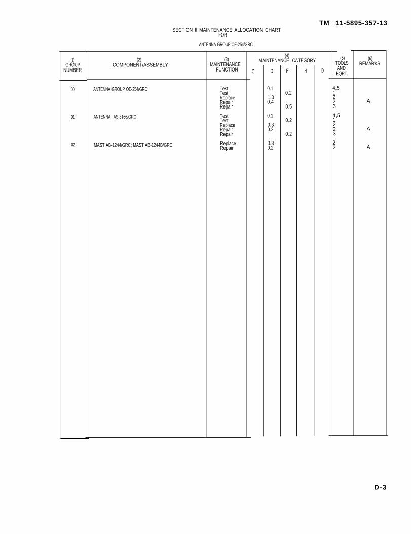
SECTION II MAINTENANCE ALLOCATION CHARTFOR
ANTENNA GROUP OE-254/GRC
(2)COMPONENT/ASSEMBLY
ANTENNA GROUP OE-254/GRC
ANTENNA AS-3166/GRC
MAST AB-1244/GRC; MAST AB-1244B/GRC
(3)MAINTENANCE
FUNCTION
TestTestReplaceRepairRepair
TestTestReplaceRepairRepair
ReplaceRepair
TM 11-5895-357-13
(4)MAINTENANCE CATEGORY
C O
0.1
1.00.4
0.1
0.30.2
0.30.2
F
0.2
0.5
0.2
0.2
H D
(5)TOOLSAND
EQPT.
4,51223
4,51223
22
(6)REMARKS
A
A
A
D-3
T M 1 1 - 5 9 8 5 - 3 5 7 - 1 3
TOOL OR TESTEQUIPMENTREF CODE
1
2
3
4
5
MAINTENANCECATEGORY
F
O
F
O
O
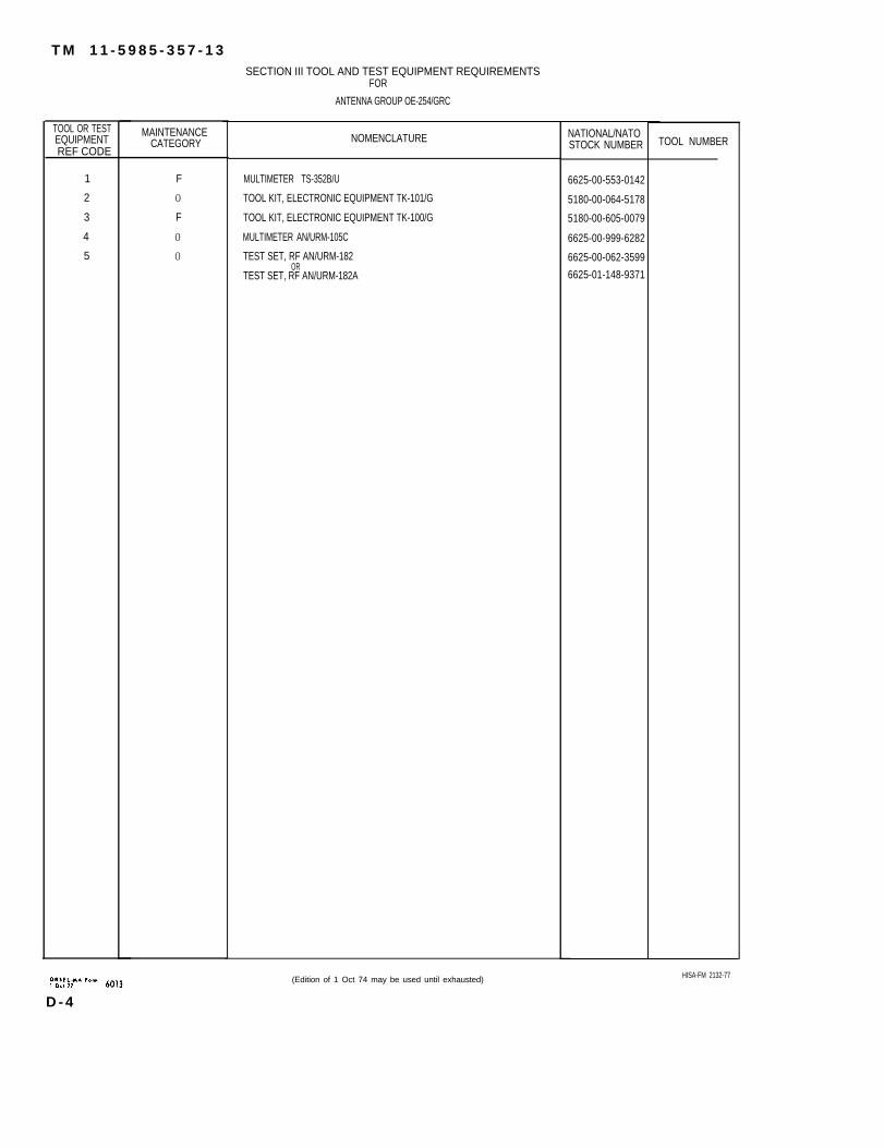
SECTION III TOOL AND TEST EQUIPMENT REQUIREMENTSFOR
ANTENNA GROUP OE-254/GRC
NOMENCLATURE
MULTIMETER TS-352B/U
TOOL KIT, ELECTRONIC EQUIPMENT TK-101/G
TOOL KIT, ELECTRONIC EQUIPMENT TK-100/G
MULTIMETER AN/URM-105C
TEST SET, RF AN/URM-182OR
TEST SET, RF AN/URM-182A
(Edition of 1 Oct 74 may be used until exhausted)
NATIONAL/NATOSTOCK NUMBER
6625-00-553-0142
5180-00-064-5178
5180-00-605-0079
6625-00-999-6282
6625-00-062-3599
6625-01-148-9371
TOOL NUMBER
HISA-FM 2132-77
D - 4
TM 11-5985-357-13
SECTION IV. REMARKS
REFERENCECODE REMARKS
A Repair is done by replacement.
D-5/(D-6 blank)
TM 11-5985-357-13
APPENDIX E
E-1. Scope
EXPENDABLE SUPPLIES AND MATERIALS LIST
Section I. INTRODUCTION
This appendix lists expendable supplies and materialsyou will need to operate and maintain the OE-254/GRC.These items are authorized to you by CTA 50-970,Expendable Items (Except Medical, Class V, RepairParts, and Heraldic Items).
E-2. Explanation of Columns
a. Column 1 — Item Number. This number isassigned to the entry in the listing and is referencedin the narrative instructions to identify the material(e.g., “Use cleaning compound, item 5, appx E”).
b. Column 2 – Level. This column identifies thelowest level of maintenance that requires the listeditem.
C – Operator/CrewO – Organizational Maintenance
F — Direct Support MaintenanceH — General Support Maintenance
c. Column 3 – National Stock Number. This is theNational stock number assigned to the item; use it torequest or requisition the item.
d. Column 4 – Description. Indicates the Federalitem name and, if required, a description to identifythe item. The last line for each item indicates the partnumber followed by the Federal Supply Code forManufacturer (FSCM) in parentheses, if applicable.
e. Column 5 — Unit of Measure (U/M). Indicatesthe measure used in performing the actualmaintenance function, This measure is expressed by atwo-character alphabetical abbreviation (e.g., ea, in,pr). If the unit of measure differs from the unit ofissue, requisition the lowest unit of issue that willsatisfy your requirements.
(Next printed page is E-2)
Change 1 E-1
TM 11-5985-357-13SECTION II EXPENDABLE SUPPLIES AND MATERIALS LIST
(1) (2) (3) (4) (5)ITEM LEVEL NATIONAL DESCRIPTION UNIT
No. STOCK OFNUMBER MEAS
PART NO AND FSCM
1 C 5970-00-419-4291 ELECTRICAL TAPE RL
2 C 6850-00-880-7616 SILICONE COMPOUND TU
4 O 8010-01-039-5939 PAINT, ALKYD, CAMOUFLAGE, FOREST GREEN QTMIL-E-52798
5 O 9905-00-511-8751 WARNING LABEL (SB 11-614) EA
E-2 Change 3
By Order of the Secretary of the Army:
CARL E. VUONOGeneral, United States Army
Chief of Staff
Official:
PATRICIA P. HICKERSONColonel, United States Army
The Adjutant General
DISTRIBUTION:
To be distributed in accordance with DA Form 12-51–E,block 9749, Operator, Unit and Direct Support/GeneralSupport Maintenance requirements for TM 11-5985-357-13.
✩ U.S. GOVERNMENT PRINTING OFFICE: 1995-387-868/32288