55
Antennas and RF Considerations for Outdoor WLANs Chuck Lukaszewski, Director of Professional Services
Aruba Networks CONFIDENTIAL. © 2010 All Rights Reserved.
Antennas and RF Considerations for Outdoor WLANs Chuck Lukaszewski, Director of Professional Services
Aruba Networks CONFIDENTIAL. © 2010 All Rights Reserved.
Agenda
1. The need for the Outdoor WLAN
2. Antenna Radiation Principles & Patterns
3. Mechanical Downtilt
4. 3D Visualization and Outdoor Coverage Strategies
5. Outdoor Physical Installation Basics
6. Case Study – Railyard
7. Case Study – University Campus
8. Case Study – Manufacturing Plant
Aruba Networks CONFIDENTIAL. © 2010 All Rights Reserved.
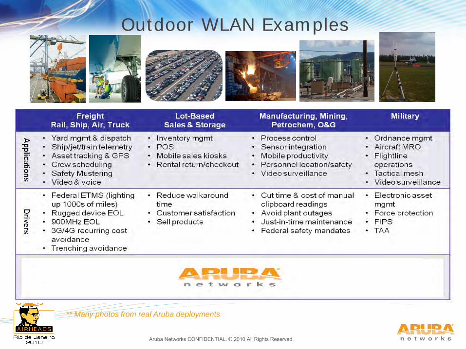
Outdoor WLAN Examples
** Many photos from real Aruba deployments
Aruba Networks CONFIDENTIAL. © 2010 All Rights Reserved.
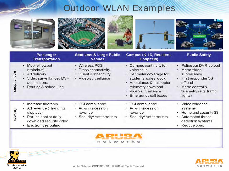
Outdoor WLAN Examples
Aruba Networks CONFIDENTIAL. © 2010 All Rights Reserved.
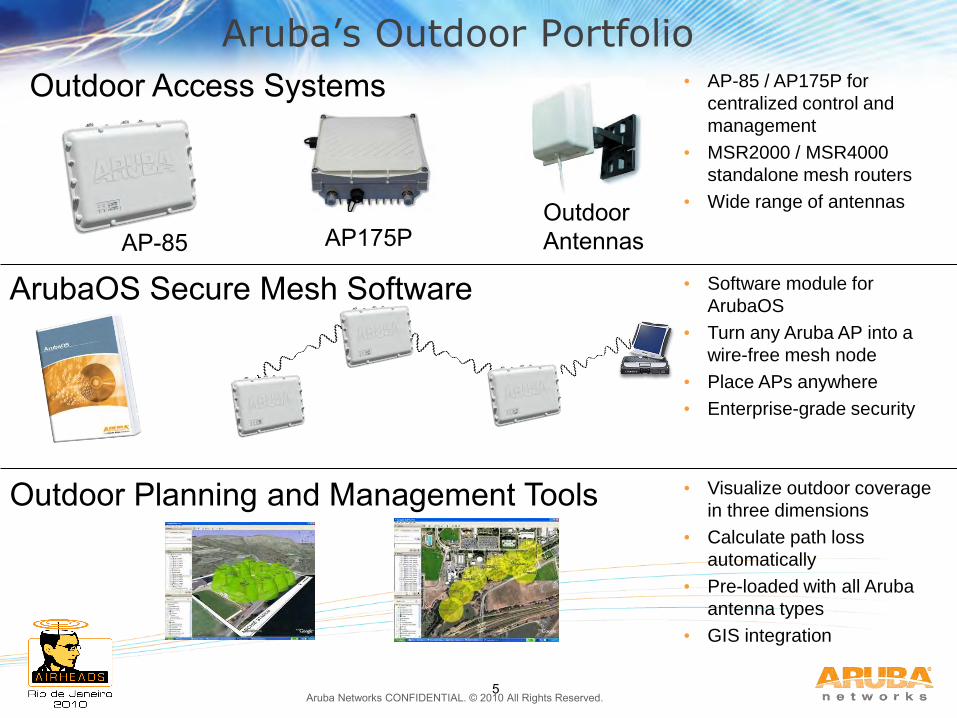
Aruba’s Outdoor Portfolio
5
ArubaOS Secure Mesh Software • Software module for
ArubaOS
• Turn any Aruba AP into a
wire-free mesh node
• Place APs anywhere
• Enterprise-grade security
Outdoor Access Systems
Outdoor Planning and Management Tools • Visualize outdoor coverage
in three dimensions
• Calculate path loss
automatically
• Pre-loaded with all Aruba
antenna types
• GIS integration
• AP-85 / AP175P for
centralized control and
management
• MSR2000 / MSR4000
standalone mesh routers
• Wide range of antennas
AP-85 AP175P Outdoor Antennas
Aruba Networks CONFIDENTIAL. © 2010 All Rights Reserved.
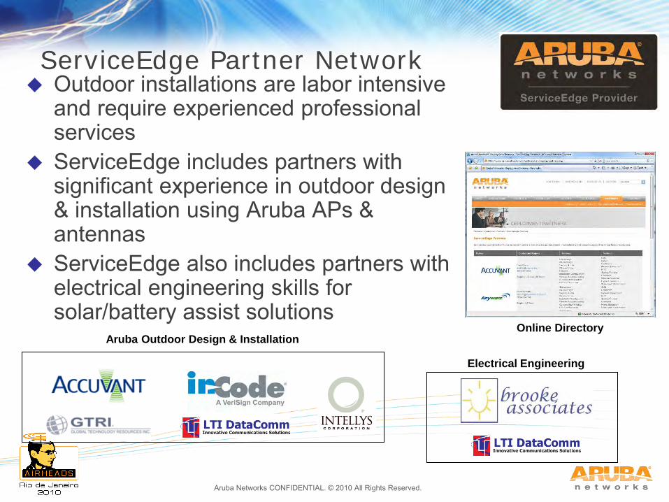
ServiceEdge Partner Network Outdoor installations are labor intensive
and require experienced professional services
ServiceEdge includes partners with significant experience in outdoor design & installation using Aruba APs & antennas
ServiceEdge also includes partners with electrical engineering skills for solar/battery assist solutions
Online Directory Aruba Outdoor Design & Installation
Electrical Engineering
Aruba Networks CONFIDENTIAL. © 2010 All Rights Reserved.
Agenda
1. The need for the Outdoor WLAN
2. Antenna Radiation Principles & Patterns
3. Mechanical Downtilt
4. 3D Visualization and Outdoor Coverage Strategies
5. Outdoor Physical Installation Basics
6. Case Study – Railyard
7. Case Study – University Campus
8. Case Study – Manufacturing Plant
Aruba Networks CONFIDENTIAL. © 2010 All Rights Reserved. 3-8
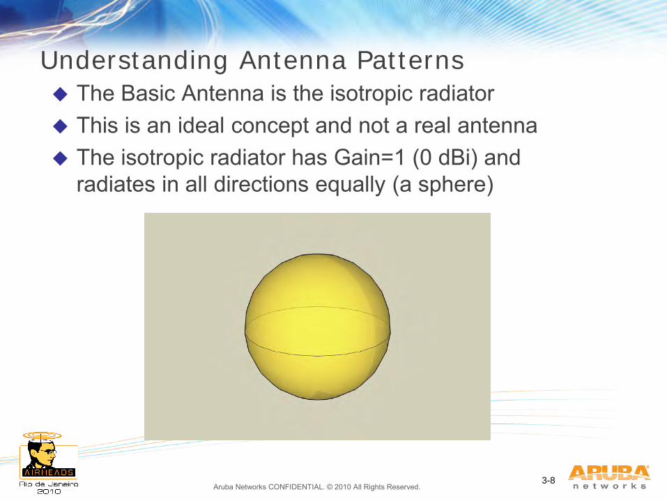
Understanding Antenna Patterns
The Basic Antenna is the isotropic radiator This is an ideal concept and not a real antenna The isotropic radiator has Gain=1 (0 dBi) and
radiates in all directions equally (a sphere)
Aruba Networks CONFIDENTIAL. © 2010 All Rights Reserved. 3-9
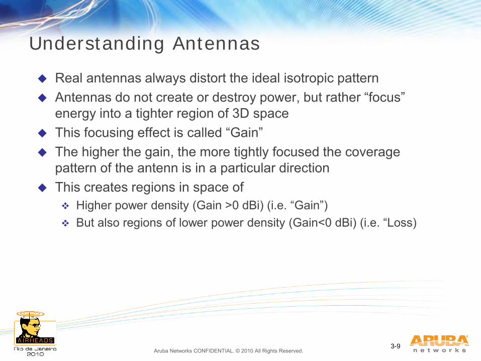
Understanding Antennas
Real antennas always distort the ideal isotropic pattern Antennas do not create or destroy power, but rather “focus”
energy into a tighter region of 3D space This focusing effect is called “Gain” The higher the gain, the more tightly focused the coverage
pattern of the antenn is in a particular direction This creates regions in space of
Higher power density (Gain >0 dBi) (i.e. “Gain”) But also regions of lower power density (Gain<0 dBi) (i.e. “Loss)
Aruba Networks CONFIDENTIAL. © 2010 All Rights Reserved. 3-10
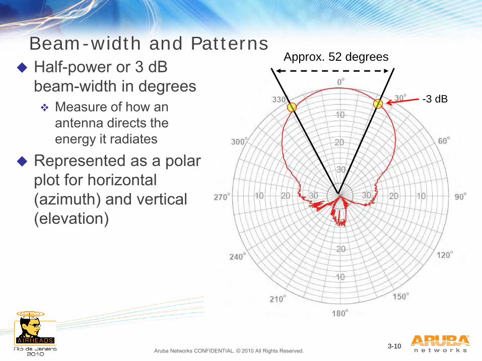
Beam-width and Patterns Half-power or 3 dB
beam-width in degrees Measure of how an
antenna directs the energy it radiates
Represented as a polar plot for horizontal (azimuth) and vertical (elevation)
Approx. 52 degrees
-3 dB
Aruba Networks CONFIDENTIAL. © 2010 All Rights Reserved. 3-11
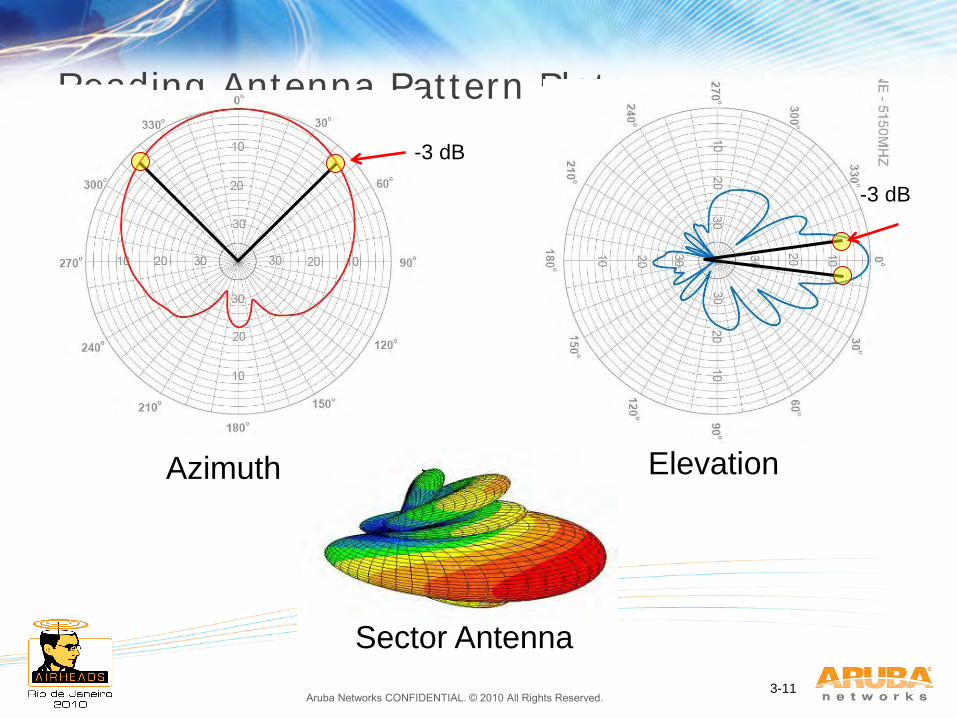
Reading Antenna Pattern Plots
Azimuth Elevation
Sector Antenna
-3 dB
-3 dB
Aruba Networks CONFIDENTIAL. © 2010 All Rights Reserved. 3-12
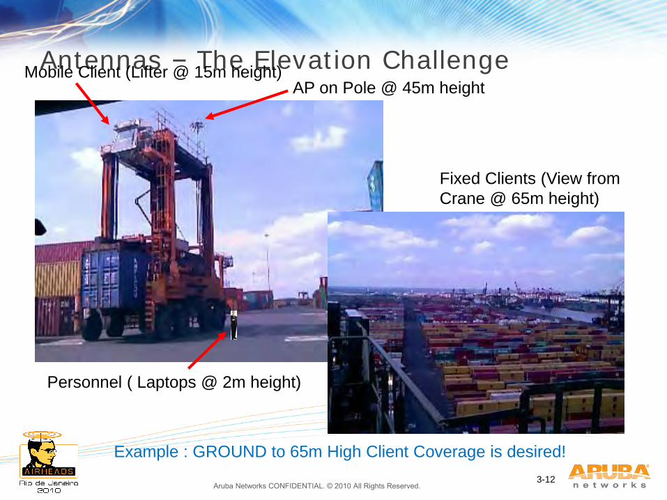
Antennas – The Elevation Challenge AP on Pole @ 45m height
Mobile Client (Lifter @ 15m height)
Fixed Clients (View from
Crane @ 65m height)
Personnel ( Laptops @ 2m height)
Example : GROUND to 65m High Client Coverage is desired!
Aruba Networks CONFIDENTIAL. © 2010 All Rights Reserved. 3-13
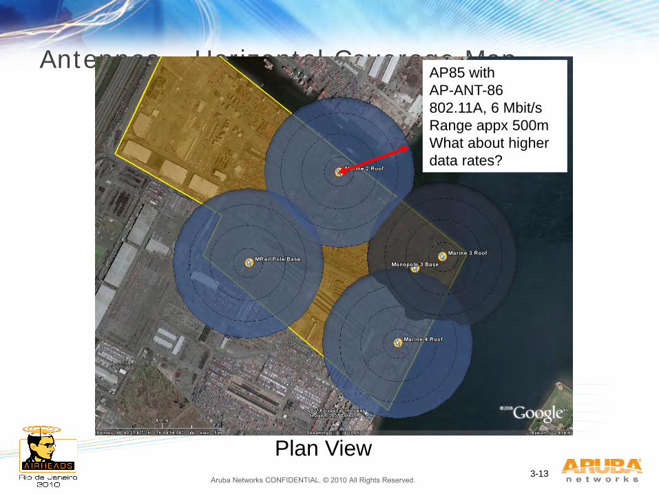
Antennas – Horizontal Coverage Map AP85 with
AP-ANT-86
802.11A, 6 Mbit/s
Range appx 500m
What about higher
data rates?
Plan View
Aruba Networks CONFIDENTIAL. © 2010 All Rights Reserved. 3-14
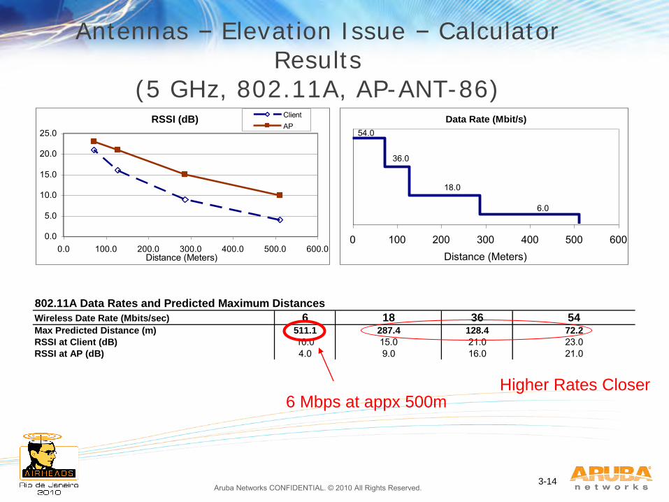
Antennas – Elevation Issue – Calculator Results
(5 GHz, 802.11A, AP-ANT-86)
802.11A Data Rates and Predicted Maximum Distances 6 18 36 54
Max Predicted Distance (m) 511.1 287.4 128.4 72.2
RSSI at Client (dB) 10.0 15.0 21.0 23.0RSSI at AP (dB) 4.0 9.0 16.0 21.0
Wireless Date Rate (Mbits/sec)
RSSI (dB)
0.0
5.0
10.0
15.0
20.0
25.0
0.0 100.0 200.0 300.0 400.0 500.0 600.0Distance (Meters)
ClientAP
Data Rate (Mbit/s)
6.0
18.0
36.0
54.0
0 100 200 300 400 500 600Distance (Meters)
6 Mbps at appx 500m Higher Rates Closer
Aruba Networks CONFIDENTIAL. © 2010 All Rights Reserved. 3-15
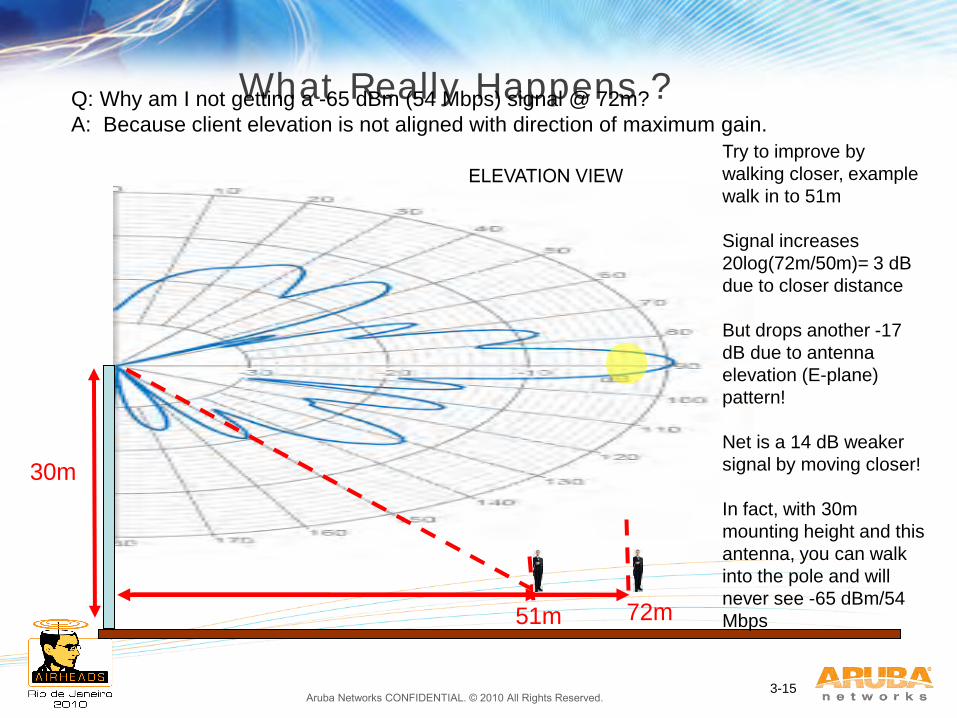
What Really Happens ?
30m
72m
Try to improve by
walking closer, example
walk in to 51m
Signal increases
20log(72m/50m)= 3 dB
due to closer distance
But drops another -17
dB due to antenna
elevation (E-plane)
pattern!
Net is a 14 dB weaker
signal by moving closer!
In fact, with 30m
mounting height and this
antenna, you can walk
into the pole and will
never see -65 dBm/54
Mbps
Q: Why am I not getting a -65 dBm (54 Mbps) signal @ 72m?
A: Because client elevation is not aligned with direction of maximum gain.
51m
ELEVATION VIEW
Aruba Networks CONFIDENTIAL. © 2010 All Rights Reserved.
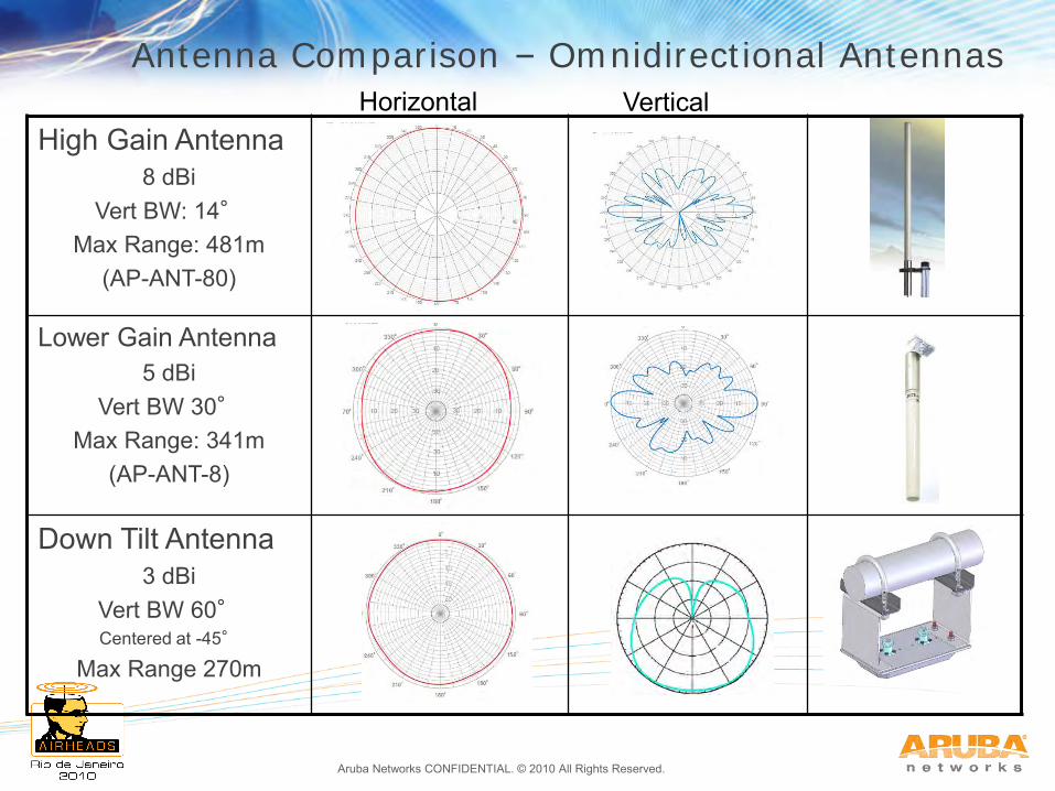
High Gain Antenna 8 dBi
Vert BW: 14° Max Range: 481m
(AP-ANT-80)
Lower Gain Antenna 5 dBi
Vert BW 30° Max Range: 341m
(AP-ANT-8)
Down Tilt Antenna 3 dBi
Vert BW 60° Centered at -45°
Max Range 270m
Horizontal Vertical Antenna Comparison – Omnidirectional Antennas
Aruba Networks CONFIDENTIAL. © 2010 All Rights Reserved.
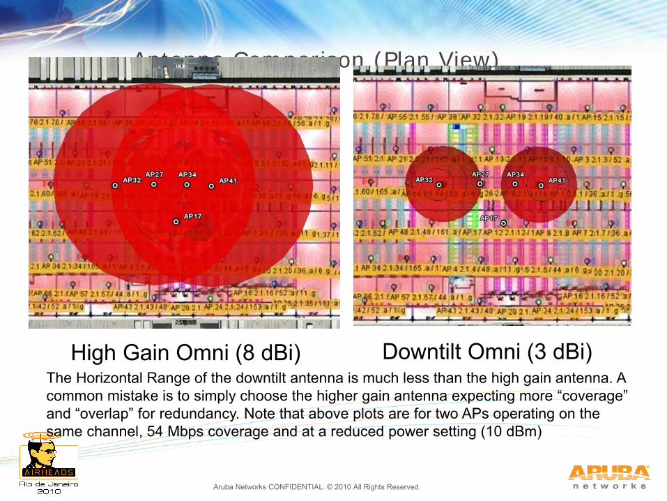
Antenna Comparison (Plan View)
High Gain Omni (8 dBi) The Horizontal Range of the downtilt antenna is much less than the high gain antenna. A common mistake is to simply choose the higher gain antenna expecting more “coverage” and “overlap” for redundancy. Note that above plots are for two APs operating on the same channel, 54 Mbps coverage and at a reduced power setting (10 dBm)
Downtilt Omni (3 dBi)
Aruba Networks CONFIDENTIAL. © 2010 All Rights Reserved.
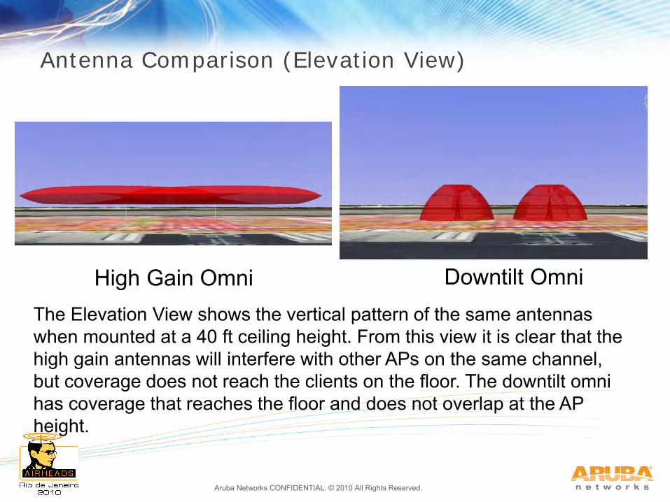
Antenna Comparison (Elevation View)
High Gain Omni Downtilt Omni The Elevation View shows the vertical pattern of the same antennas when mounted at a 40 ft ceiling height. From this view it is clear that the high gain antennas will interfere with other APs on the same channel, but coverage does not reach the clients on the floor. The downtilt omni has coverage that reaches the floor and does not overlap at the AP height.
Aruba Networks CONFIDENTIAL. © 2010 All Rights Reserved.
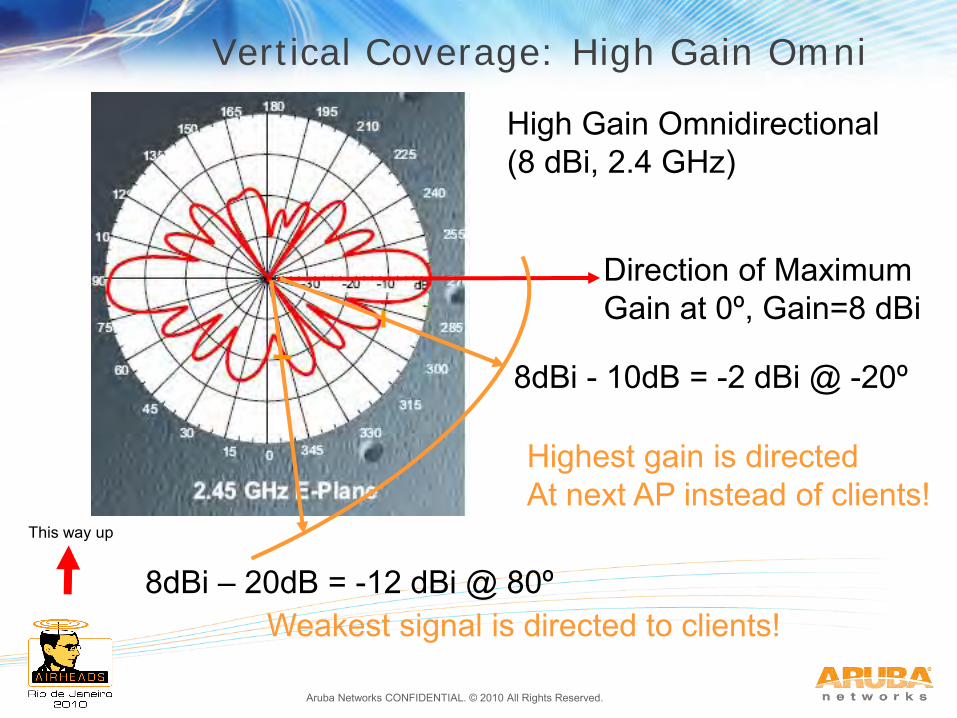
Direction of Maximum Gain at 0º, Gain=8 dBi
8dBi - 10dB = -2 dBi @ -20º
8dBi – 20dB = -12 dBi @ 80º
High Gain Omnidirectional (8 dBi, 2.4 GHz)
This way up
Highest gain is directed At next AP instead of clients!
Weakest signal is directed to clients!
Vertical Coverage: High Gain Omni
Aruba Networks CONFIDENTIAL. © 2010 All Rights Reserved.
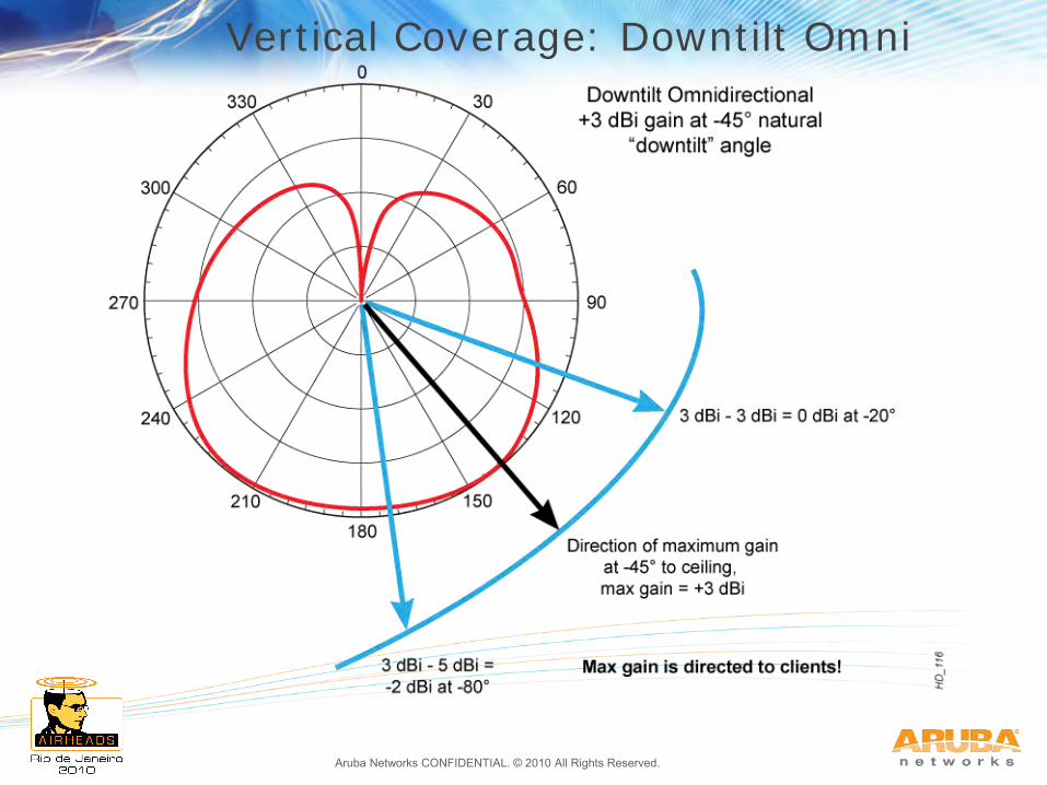
Vertical Coverage: Downtilt Omni
Aruba Networks CONFIDENTIAL. © 2010 All Rights Reserved.
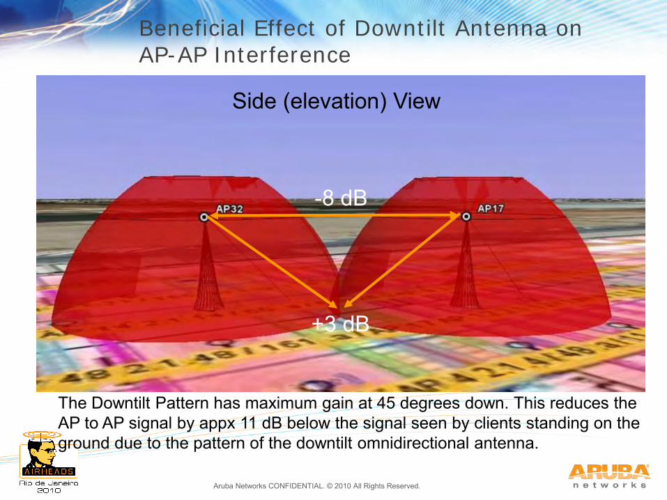
Beneficial Effect of Downtilt Antenna on AP-AP Interference
The Downtilt Pattern has maximum gain at 45 degrees down. This reduces the AP to AP signal by appx 11 dB below the signal seen by clients standing on the ground due to the pattern of the downtilt omnidirectional antenna.
-8 dB
+3 dB
Side (elevation) View
Aruba Networks CONFIDENTIAL. © 2010 All Rights Reserved. 3-22
Summary: Antenna Basics Higher Gain is always at the expense of coverage,
usually vertical coverage. Always think about the direction of gain relative to the
client locations. Clients should be within the -3 dB Area (horizontal and vertical) whenever possible.
For successful outdoor (or large indoor) planning, vertical coverage is usually a critical design requirement. Pay attention to the vertical pattern plots and the elevation of the clients relative to the proposed mounting heights.
For overhead installation, outdoor down tilt antenna (AP-ANT-90) helps considerably with very high mounting conditions (6m up to 50m) in some of the most challenging environments such as container facilities.
Aruba Networks CONFIDENTIAL. © 2010 All Rights Reserved.
Agenda
1. Aruba Outdoor Products & Experience
2. Antenna Radiation Principles & Patterns
3. Mechanical Downtilt
4. 3D Visualization and Outdoor Coverage Strategies
5. Outdoor Physical Installation Basics
6. Case Study – Railyard
7. Case Study – University Campus
8. Case Study – Manufacturing Plant
Aruba Networks CONFIDENTIAL. © 2010 All Rights Reserved. 3-24
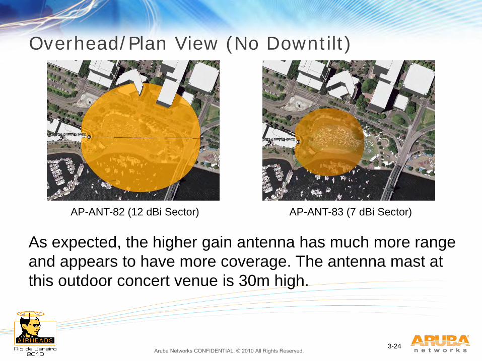
Overhead/Plan View (No Downtilt)
AP-ANT-82 (12 dBi Sector) AP-ANT-83 (7 dBi Sector)
As expected, the higher gain antenna has much more range
and appears to have more coverage. The antenna mast at
this outdoor concert venue is 30m high.
Aruba Networks CONFIDENTIAL. © 2010 All Rights Reserved. 3-25
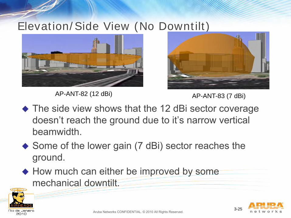
Elevation/Side View (No Downtilt)
The side view shows that the 12 dBi sector coverage doesn’t reach the ground due to it’s narrow vertical beamwidth.
Some of the lower gain (7 dBi) sector reaches the ground.
How much can either be improved by some mechanical downtilt.
AP-ANT-82 (12 dBi) AP-ANT-83 (7 dBi)
Aruba Networks CONFIDENTIAL. © 2010 All Rights Reserved. 3-26
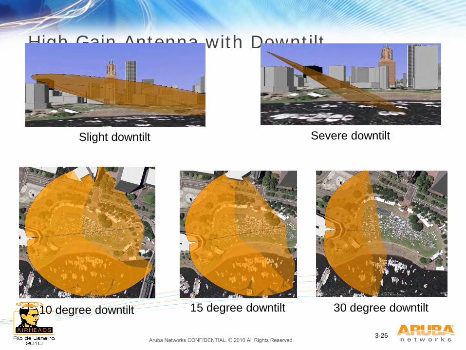
High Gain Antenna with Downtilt
10 degree downtilt 15 degree downtilt 30 degree downtilt
Slight downtilt Severe downtilt
Aruba Networks CONFIDENTIAL. © 2010 All Rights Reserved. 3-27
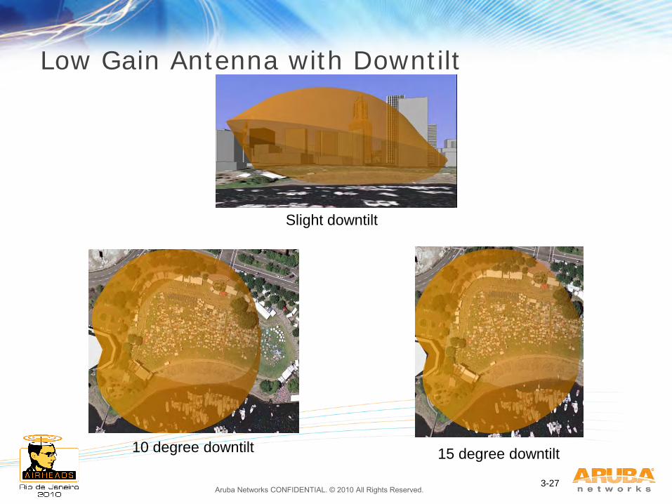
Low Gain Antenna with Downtilt
10 degree downtilt 15 degree downtilt
Slight downtilt
Aruba Networks CONFIDENTIAL. © 2010 All Rights Reserved. 3-28
Summary: Mechanical Downtilt High-gain antennas have very narrow vertical
beamwidths Even relatively modest mounting heights (e.g. 10m-
15m) and small mechanical downtilts (e.g. 10-15 degrees) result in the “striping” effect on the ground which significantly reduces coverage
Mechanical downtilt is ineffective as a solution to compensate for narrow vertical beamwidth
Narrow vertical-beamwidth (i.e. high gain) antennas are best utilized for long-distance point-to-point links and not as client access antennas unless the elevation between the clients and the antennas is very carefully controlled, typically a maximum of 2m separation in elevation between clients and antennas is recommended for antennas with gain >5 dBi.
Aruba Networks CONFIDENTIAL. © 2010 All Rights Reserved.
Agenda
1. Aruba Outdoor Products & Experience
2. Antenna Radiation Principles & Patterns
3. Mechanical Downtilt
4. 3D Visualization and Outdoor Coverage Strategies
5. Outdoor Physical Installation Basics
6. Case Study – Railyard
7. Case Study – University Campus
8. Case Study – Manufacturing Plant
Aruba Networks CONFIDENTIAL. © 2010 All Rights Reserved.
Aruba Networks has developed a proprietary outdoor planning and mesh visualization tool
Uses Patent Pending process to render and display 3D coverage models from AP settings and coverage patterns of antennas used
Accounts for actual antenna mounting heights, downtilt and terrain effects
Model/Planning output is viewable in Google Earth and other GIS (kml compatible) systems
Aruba Networks Outdoor 3D Visualization
Aruba Networks CONFIDENTIAL. © 2010 All Rights Reserved.
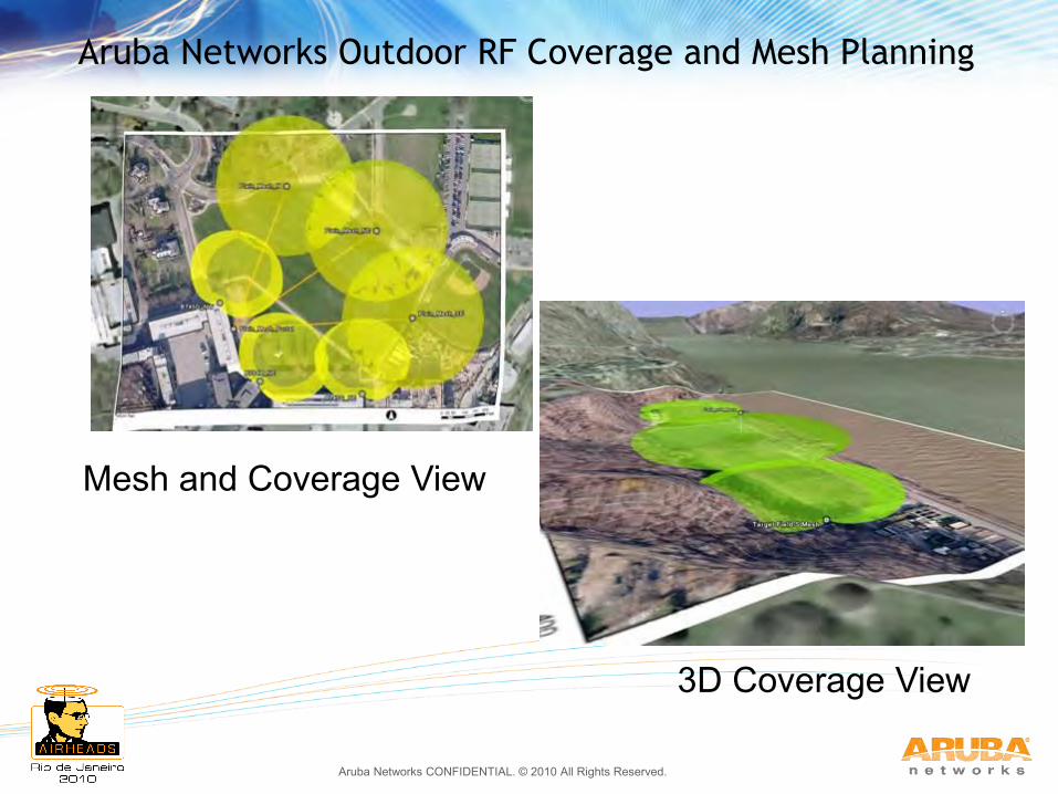
Aruba Networks Outdoor RF Coverage and Mesh Planning
Mesh and Coverage View
3D Coverage View
Aruba Networks CONFIDENTIAL. © 2010 All Rights Reserved.
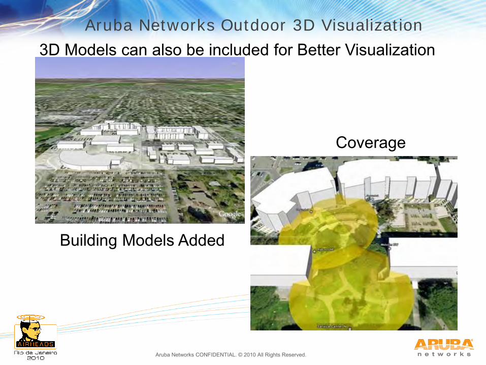
3D Models can also be included for Better Visualization
Coverage
Building Models Added
Aruba Networks Outdoor 3D Visualization
Aruba Networks CONFIDENTIAL. © 2010 All Rights Reserved.
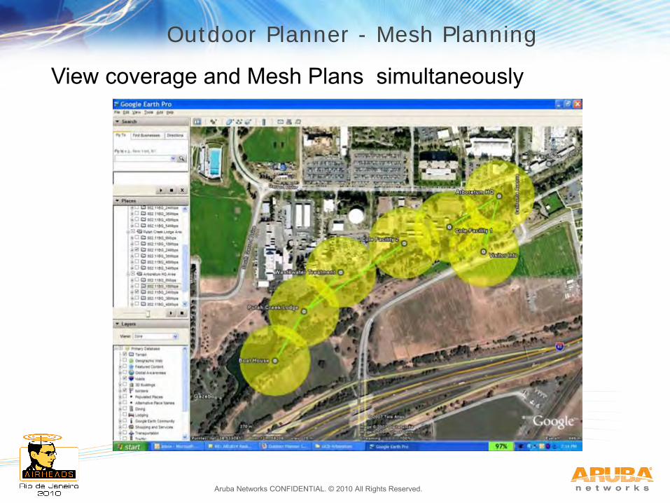
Outdoor Planner - Mesh Planning
View coverage and Mesh Plans simultaneously
Aruba Networks CONFIDENTIAL. © 2010 All Rights Reserved.
Agenda
1. Aruba Outdoor Products & Experience
2. Antenna Radiation Principles & Patterns
3. Mechanical Downtilt
4. 3D Visualization and Outdoor Coverage Strategies
5. Outdoor Physical Installation Basics
6. Case Study – Railyard
7. Case Study – University Campus
8. Case Study – Manufacturing Plant
Aruba Networks CONFIDENTIAL. © 2010 All Rights Reserved. 3-35
Safety and Compliance
Aruba Access Points, antennas, and the AP-LAR-1 lightning arrestor are required to be installed by a professional installer
The professional installer is responsible for ensuring that grounding is available and it meets applicable local and national electrical codes
Do not work on an AP and do not connect or disconnect cables during periods of lightning activity
Never stand in front of any antenna system
Aruba Networks CONFIDENTIAL. © 2010 All Rights Reserved.
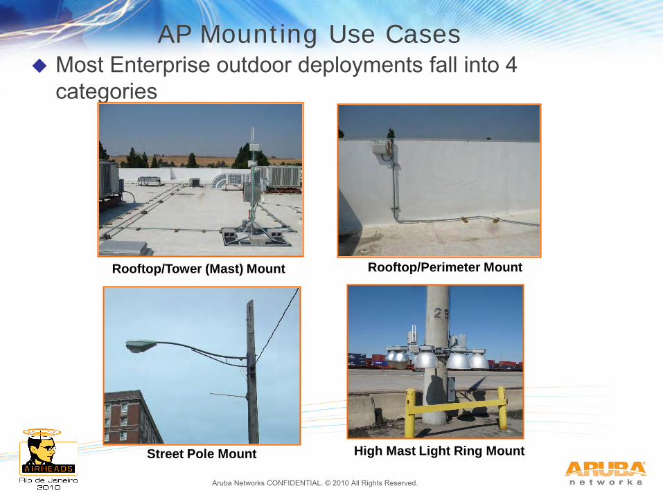
AP Mounting Use Cases Most Enterprise outdoor deployments fall into 4
categories
Rooftop/Tower (Mast) Mount
Street Pole Mount
Rooftop/Perimeter Mount
High Mast Light Ring Mount
Aruba Networks CONFIDENTIAL. © 2010 All Rights Reserved.
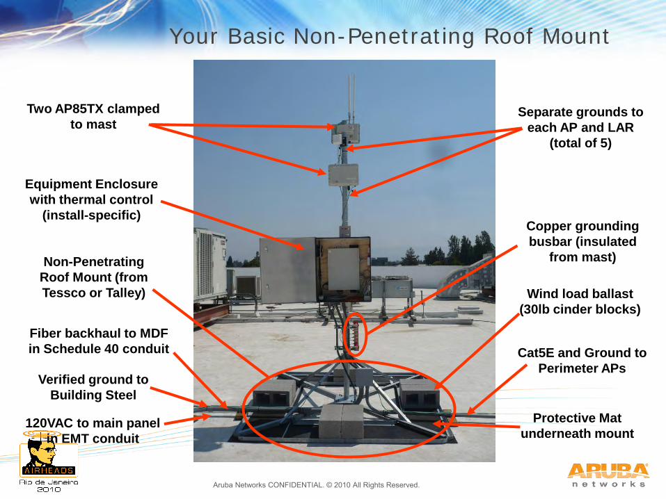
Your Basic Non-Penetrating Roof Mount
Non-Penetrating
Roof Mount (from
Tessco or Talley)
Cat5E and Ground to
Perimeter APs
Fiber backhaul to MDF
in Schedule 40 conduit
120VAC to main panel
in EMT conduit
Verified ground to
Building Steel
Protective Mat
underneath mount
Wind load ballast
(30lb cinder blocks)
Equipment Enclosure
with thermal control
(install-specific)
Two AP85TX clamped
to mast
Copper grounding
busbar (insulated
from mast)
Separate grounds to
each AP and LAR
(total of 5)
Aruba Networks CONFIDENTIAL. © 2010 All Rights Reserved.
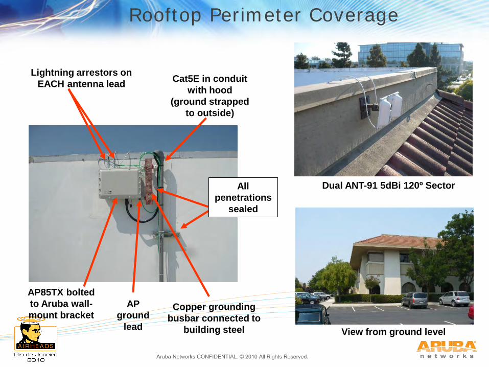
Rooftop Perimeter Coverage
Dual ANT-91 5dBi 120º Sector
View from ground level
AP85TX bolted
to Aruba wall-
mount bracket
Lightning arrestors on
EACH antenna lead
Copper grounding
busbar connected to
building steel
Cat5E in conduit
with hood
(ground strapped
to outside)
All
penetrations
sealed
AP
ground
lead
Aruba Networks CONFIDENTIAL. © 2010 All Rights Reserved.
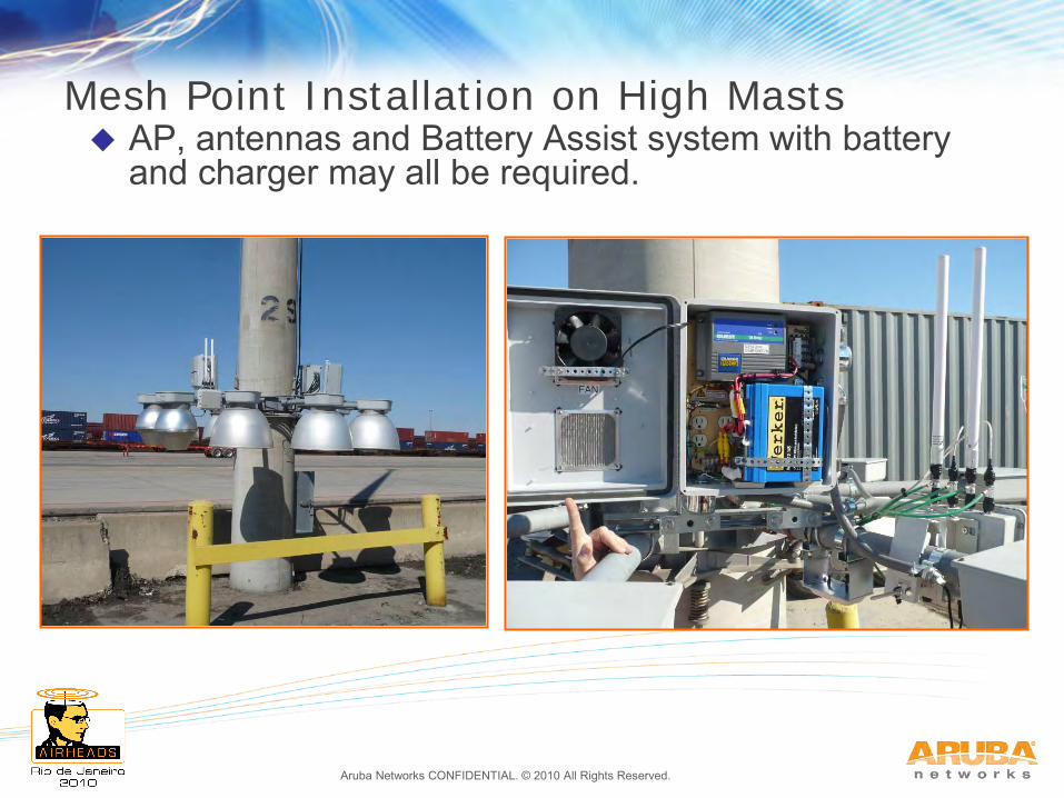
Mesh Point Installation on High Masts AP, antennas and Battery Assist system with battery
and charger may all be required.

Aruba Networks CONFIDENTIAL. © 2010 All Rights Reserved.
Agenda
1. Aruba Outdoor Products & Experience
2. Antenna Radiation Principles & Patterns
3. Mechanical Downtilt
4. 3D Visualization and Outdoor Coverage Strategies
5. Outdoor Physical Installation Basics
6. Case Study – Railyard
7. Case Study – University Campus
8. Case Study – Manufacturing Plant
Aruba Networks CONFIDENTIAL. © 2010 All Rights Reserved.
Outdoor Yard Coverage Strategies
There are three basic RF design strategies for large outdoor facilities:
1. Sparse Side Coverage 2. Dense Side Coverage 3. Dense Overhead Coverage
Definitions Coverage is sparse when a small number of locations cover
a large space with high-gain directional antennas Coverage is dense when many APs that are relatively
evenly spaced cover a large area with low-gain antennas Side coverage means that the main lobe of the antenna is
approximately the same elevation as the clients being served
Overhead coverage refers to the use of “squint” or downtilt antennas that face downwards but offer 360 degree pattern
Aruba Networks CONFIDENTIAL. © 2010 All Rights Reserved.
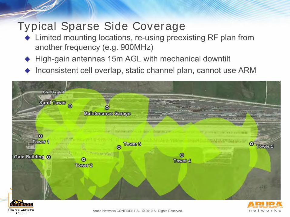
Typical Sparse Side Coverage Limited mounting locations, re-using preexisting RF plan from
another frequency (e.g. 900MHz) High-gain antennas 15m AGL with mechanical downtilt Inconsistent cell overlap, static channel plan, cannot use ARM
Aruba Networks CONFIDENTIAL. © 2010 All Rights Reserved.
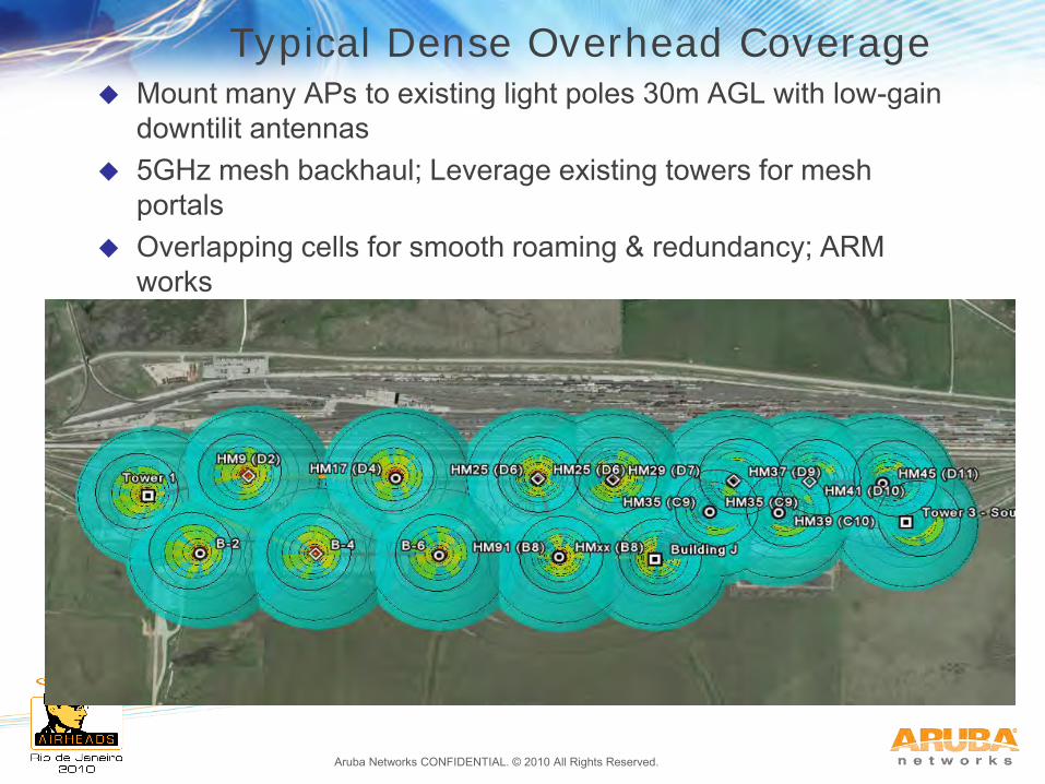
Typical Dense Overhead Coverage Mount many APs to existing light poles 30m AGL with low-gain
downtilit antennas 5GHz mesh backhaul; Leverage existing towers for mesh
portals Overlapping cells for smooth roaming & redundancy; ARM
works
Aruba Networks CONFIDENTIAL. © 2010 All Rights Reserved.
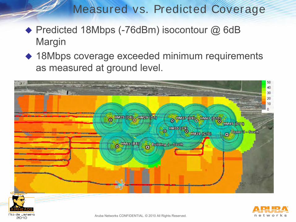
Measured vs. Predicted Coverage
Predicted 18Mbps (-76dBm) isocontour @ 6dB Margin
18Mbps coverage exceeded minimum requirements as measured at ground level.
Aruba Networks CONFIDENTIAL. © 2010 All Rights Reserved.
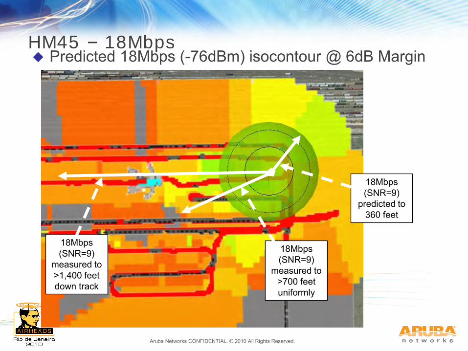
HM45 – 18Mbps Predicted 18Mbps (-76dBm) isocontour @ 6dB Margin
18Mbps (SNR=9)
predicted to 360 feet
18Mbps (SNR=9)
measured to >700 feet uniformly
18Mbps (SNR=9)
measured to >1,400 feet down track
Aruba Networks CONFIDENTIAL. © 2010 All Rights Reserved.
Agenda
1. Aruba Outdoor Products & Experience
2. Antenna Radiation Principles & Patterns
3. Mechanical Downtilt
4. 3D Visualization and Outdoor Coverage Strategies
5. Outdoor Physical Installation Basics
6. Case Study – Railyard
7. Case Study – University Campus
8. Case Study – Manufacturing Plant
Aruba Networks CONFIDENTIAL. © 2010 All Rights Reserved.
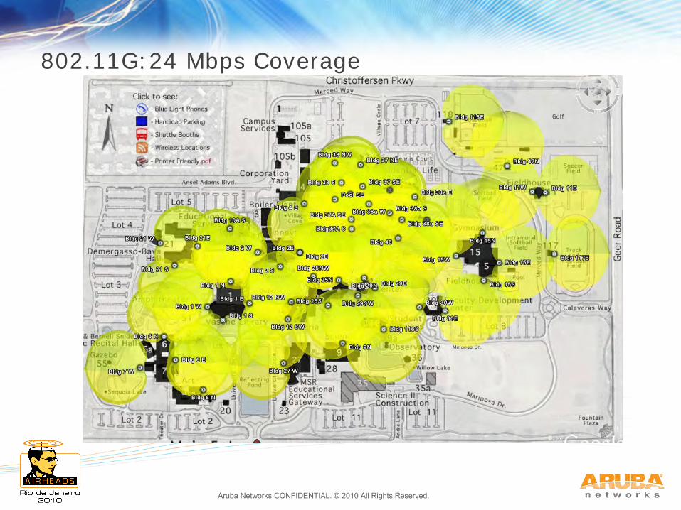
University Campus
AP count is driven by Users/AP for dense areas and building locations (i.e. getting around them)
Design goal was 3-4 AP’s visible to users in dense areas, and 2 AP’s visible everywhere else
10 dB design margin is conservative but recommended due to trees/buildings/bodies
Above strategy results in 54 APs for the initial coverage shown, up to 70 APs are recommended to provide coverage of perimeter areas such as parking lots, etc. presently shown uncovered in following slides.
Aruba Networks CONFIDENTIAL. © 2010 All Rights Reserved.
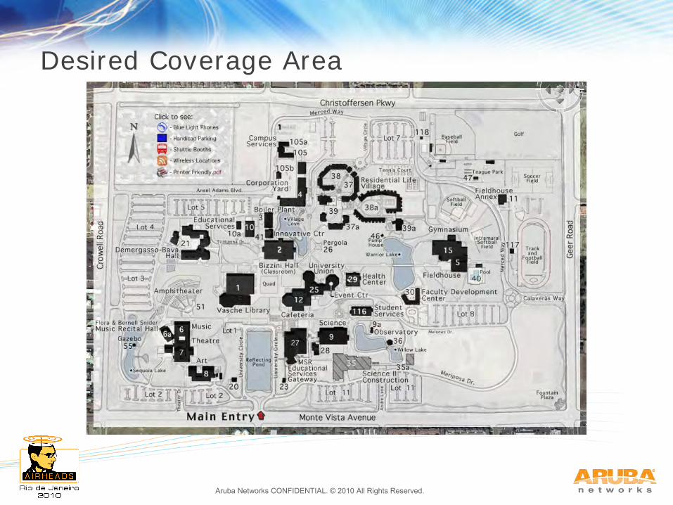
Desired Coverage Area
Aruba Networks CONFIDENTIAL. © 2010 All Rights Reserved.
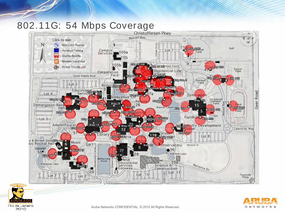
802.11G: 54 Mbps Coverage
Aruba Networks CONFIDENTIAL. © 2010 All Rights Reserved.
802.11G:24 Mbps Coverage

Aruba Networks CONFIDENTIAL. © 2010 All Rights Reserved.
Agenda
1. Aruba Outdoor Products & Experience
2. Antenna Radiation Principles & Patterns
3. Mechanical Downtilt
4. 3D Visualization and Outdoor Coverage Strategies
5. Outdoor Physical Installation Basics
6. Case Study – Railyard
7. Case Study – University Campus
8. Case Study – Manufacturing Plant
Aruba Networks CONFIDENTIAL. © 2010 All Rights Reserved.
Coverage Requirement – Manufacturing Plant
5 Mesh Portals mounted to main plant providing backhaul on 5Ghz and client service on 2.4Ghz ANT-91 (5dBi dual-band) for both
2 Mesh Points mounted to Guard Building and Pump Building with 5Ghz backhaul only to provide local wireless service.
14 Mesh Points mounted to standard street lights powered via AC power tap with backhaul on 5Ghz and client service on 2.4Ghz
Aruba Networks CONFIDENTIAL. © 2010 All Rights Reserved.
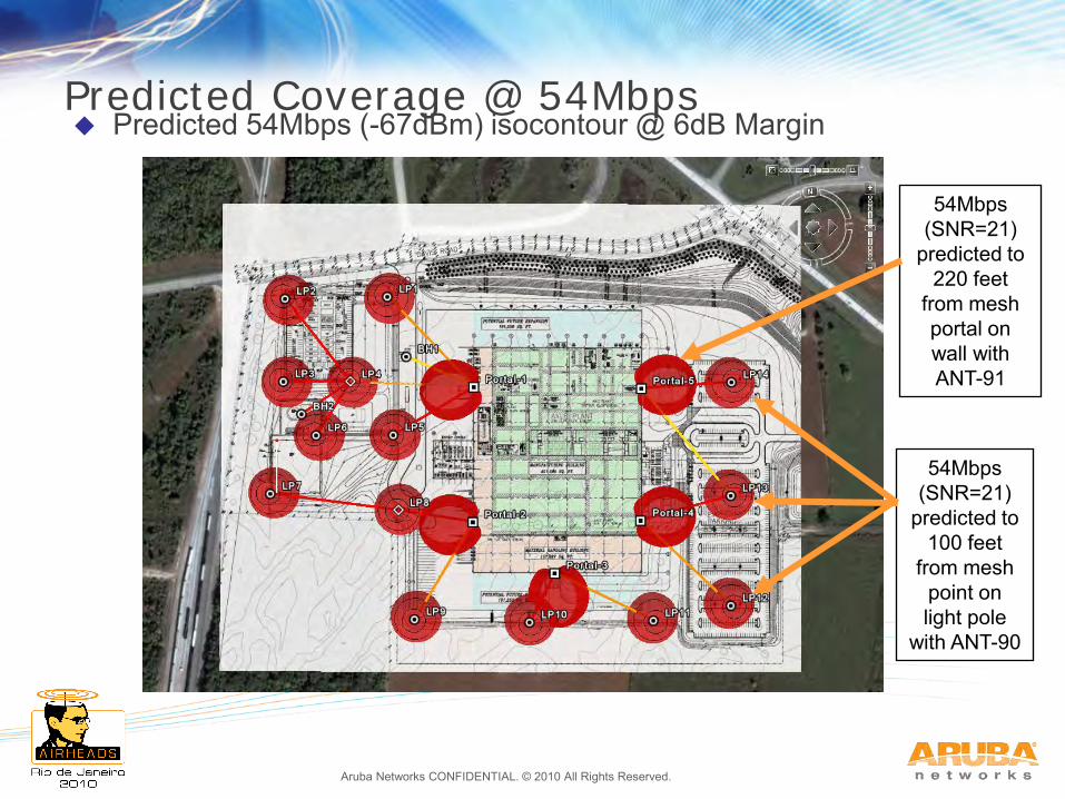
Predicted Coverage @ 54Mbps Predicted 54Mbps (-67dBm) isocontour @ 6dB Margin
54Mbps
(SNR=21) predicted to
220 feet from mesh portal on wall with ANT-91
54Mbps (SNR=21)
predicted to 100 feet
from mesh point on light pole
with ANT-90
Aruba Networks CONFIDENTIAL. © 2010 All Rights Reserved.
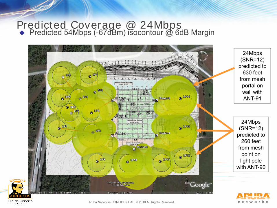
Predicted Coverage @ 24Mbps Predicted 54Mbps (-67dBm) isocontour @ 6dB Margin
24Mbps
(SNR=12) predicted to
630 feet from mesh portal on wall with ANT-91
24Mbps (SNR=12)
predicted to 260 feet
from mesh point on light pole
with ANT-90
Aruba Networks CONFIDENTIAL. © 2010 All Rights Reserved.
Thank You!


