– 1 – Introduction This application note is intended for designers who are incorporating RF into Part 15-compliant designs. It is designed to give the reader a basic understanding of an antenna’s function, operational characteristics, and evaluation techniques. It will also briefly touch on design considerations for the three most common low-power antenna styles: the whip, helical and loop trace. What Is an Antenna? A RF antenna is defined as a component that facilitates the transfer of a guided wave into, and the reception from, free space. In function, the antenna is essentially a transducer that converts alternating currents into electromagnetic fields or vice versa. The physical components that make up an antenna’s structure are called elements. From a coat hanger to a tuned Yagi, there are literally hundreds of antenna styles and variations that may be employed. Receive and transmit antennas are very alike in characteristics and in many cases are virtual mirror images of each other. However, in many Part 15 applications it is advantageous to select different characteristics for the transmitter and receiver antennas. For this reason, we will address each separately. The Transmitter Antenna The transmitter antenna allows RF energy to be efficiently radiated from the output stage into free space. In many modular and discrete transmitter designs, the transmitter’s output power is purposefully set higher than the legal limit. This allows a designer to utilize an inefficient antenna to achieve size, cost, or cosmetic objectives and still radiate the maximum allowed output power. Since gain is easily realized at the transmitter, its antenna can generally be less efficient than the antenna used on the receiver. The Receiver Antenna The receiving antenna intercepts the electromagnetic waves radiated from the transmitting antenna. When these waves impinge upon the receiving antenna, they induce a small voltage in it. This voltage causes a weak current to flow, which contains the same frequency as the original current in the transmitting antenna. A receiving antenna should capture as much of the intended signal as possible and as little as possible of other off-frequency signals. Its maximum performance should be at the frequency or in the band for Antennas: Design, Application and Performance Application Note AN-00500 Revised 8/20/12
Transcript
– 1 –
IntroductionThis application note is intended for designers who are incorporating RF into Part 15-compliant designs. It is designed to give the reader a basicunderstanding of an antenna’s function, operational characteristics, and evaluation techniques. It will also briefly touch on design considerations for the three most common low-power antenna styles: the whip, helical and loop trace.
What Is an Antenna?A RF antenna is defined as a component that facilitates the transfer of a guided wave into, and the reception from, free space. In function, theantenna is essentially a transducer that converts alternating currents into electromagnetic fields or vice versa. The physical components that make up an antenna’s structure are called elements. From a coat hanger to a tuned Yagi, there are literally hundreds of antenna styles and variations that may be employed.
Receive and transmit antennas are very alike in characteristics and in many cases are virtual mirror images of each other. However, in many Part 15 applications it is advantageous to select different characteristics for the transmitter and receiver antennas. For this reason, we will address each separately.
The Transmitter AntennaThe transmitter antenna allows RF energy to be efficiently radiated from the output stage into free space. In many modular and discrete transmitter designs, the transmitter’s output power is purposefully set higher than the legal limit. This allows a designer to utilize an inefficient antenna to achieve size, cost, or cosmetic objectives and still radiate the maximum allowed output power. Since gain is easily realized at the transmitter, its antenna can generally be less efficient than the antenna used on the receiver.
The Receiver AntennaThe receiving antenna intercepts the electromagnetic waves radiated from the transmitting antenna. When these waves impinge upon the receiving antenna, they induce a small voltage in it. This voltage causes a weak current to flow, which contains the same frequency as the original currentin the transmitting antenna.
A receiving antenna should capture as much of the intended signal as possible and as little as possible of other off-frequency signals. Its maximum performance should be at the frequency or in the band for
Antennas: Design, Application and Performance
Application Note AN-00500
Revised 8/20/12
– 2 – Application Note AN-00500
which the receiver was designed. The efficiency of the receiver’s antenna is critical to maximizing range performance. Unlike the transmitter antenna, where legal operation may mandate a reduction in efficiency, the receiver’s antenna should be optimized as much as is practical.
Understanding Transmission LinesA transmission line is any medium whereby contained RF energy is transferred from one place to another. Many times a transmission line is referred to as “a length of shielded wire” or a “piece of coax”. While technically correct, such casual references often indicate a lack of understanding and respect for the complex interaction of resistance, capacitance, and inductance that is present in a transmission line.
The diameter and spacing of the conductors as well as the dielectric constant of the materials surrounding and separating the conductors plays a critical role in determining the transmission line’s properties. One of the most important of these properties is called characteristic impedance. Characteristic impedance is the value in ohms at which the voltage-to-current ratio is constant along the transmission line. All Linx modules are intended to be utilized with transmission lines having a characteristic impedance of 50 ohms.
In order to achieve the maximum transfer of RF energy from the transmis-sion line into the antenna, the characteristic impedance of the line and the antenna at frequency should be as close as possible. When this is the case the transmission line and antenna are said to be matched. When atransmission line is terminated into an antenna that differs from its charac-teristic impedance, a mismatch will exist. This means that all of the RFenergy is not transferred from the transmission line into the antenna. The energy that cannot be transferred into the antenna is reflected back on the transmission line. Since this energy is not reflected into space, it represents a loss. The ratio between the forward wave and the reflected wave is known as the Standing Wave Ratio (SWR). The ratio between the sum of the forward voltage and the reflected voltage is commonly called the Voltage Standing Wave Ratio (VSWR).
How Does an Antenna Work?The electric and magnetic fields radiated from an antenna form an electromagnetic field. This field is responsible for the propagation and reception of RF energy. To understand an antenna’s function properly, an in-depth review of voltage, current, and magnetic theory would be required. Since this is not in keeping with the basic nature of this application note, a simplistic overview will have to suffice.
Figure 1: Typical Transmission Line
Outer Insulator
Braid
Inner Insulator
Inner Conductor
– 3 – Application Note AN-00500
Assume for a moment that a coaxial transmission line was stripped and the shield and center conductor were bent at right angles to the line asillustrated. Presto, a basic antenna called a half-wave dipole has just been formed.
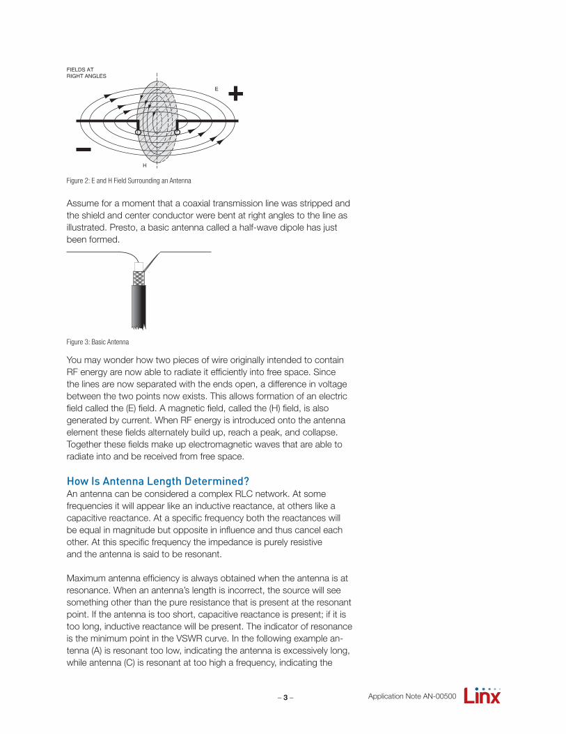
You may wonder how two pieces of wire originally intended to contain RF energy are now able to radiate it efficiently into free space. Since the lines are now separated with the ends open, a difference in voltage between the two points now exists. This allows formation of an electric field called the (E) field. A magnetic field, called the (H) field, is alsogenerated by current. When RF energy is introduced onto the antenna element these fields alternately build up, reach a peak, and collapse.Together these fields make up electromagnetic waves that are able to radiate into and be received from free space.
How Is Antenna Length Determined?An antenna can be considered a complex RLC network. At some frequencies it will appear like an inductive reactance, at others like a capacitive reactance. At a specific frequency both the reactances will be equal in magnitude but opposite in influence and thus cancel each other. At this specific frequency the impedance is purely resistiveand the antenna is said to be resonant.
Maximum antenna efficiency is always obtained when the antenna is at resonance. When an antenna’s length is incorrect, the source will seesomething other than the pure resistance that is present at the resonant point. If the antenna is too short, capacitive reactance is present; if it is too long, inductive reactance will be present. The indicator of resonance is the minimum point in the VSWR curve. In the following example an-tenna (A) is resonant too low, indicating the antenna is excessively long, while antenna (C) is resonant at too high a frequency, indicating the
FIELDS AT RIGHT ANGLES
H
E
Figure 2: E and H Field Surrounding an Antenna
Figure 3: Basic Antenna
– 4 – Application Note AN-00500
antenna is too short. Antenna (B), however, is ideal. Clearly, it is critical that an antenna is the correct length, but how is that length determined?
Every frequency has a certain physical length that it occupies in space. That length is referred to as the wavelength and is determined by two factors: 1) the frequency itself and 2) the speed of propagation.The wavelength of the operational frequency determines antenna length. Since an antenna has a dielectric constant greater than that of free space, the velocity of a wave on the antenna is slower. This along with several other factors has led antenna designers to accept the following formula as accurate for all practical purposes to determinethe physical length of a ¼-wave antenna:
While this formula is excellent for getting the antenna’s length close, the true issue is antenna resonance. Depending on physical factors such as the size and orientation of the ground plane, nearby conductors, etc., it may be necessary adjust the antenna’s length in order to reach resonance.
An antenna does not have to be the physical length of a full wave in order to operate. Often, for size and impedance considerations, the antenna will be some fraction of a full wavelength. A half-waveantenna is the shortest resonant length of an antenna. However, shorter wavelengths can be resonant on harmonics. Because of its compactlength, one of the most popular antennas for Part 15 applications is the ¼-wave whip. In this configuration, the antenna element is ¼ of a fullwavelength. In order to operate effectively, the ¼-wave must radiate against a ground plane. This plane is commonly formed by a metal case or ground area on a PCB. The ground plane acts as a counterpoise that forms the other ¼-wave element, creating in essence a half-wave dipole.
A B C
DESIRED FREQUENCY
Figure 4: Resonance Curves
L = 234FMHz
234916
= 0.255 0.255 x 12" = 3.06"
– 5 – Application Note AN-00500
IE
λ/2
HALF-WAVE DIPOLE ANTENNA (HERTZ)
I
E DIPOLEELEMENT
GROUNDPLANE
VIRTUAL λ/4DIPOLE
λ/4
λ/4
VERTICAL λ/4 GROUNDEDANTENNA (MARCONI)
Figure 5: Dipole Antenna Operation
Antenna MatchingAntenna resonance should not be confused with antenna impedance. The difference between resonance and impedance is most easilyunderstood by considering the value of VSWR at its lowest point. The lowest point of VSWR indicates the antenna is resonant, but the value of that low point is determined by the quality of the match between the antenna and the transmission line it is attached to. This point of attach-ment is called the feedpoint. In the diagram below you will notice that both antenna (A) and antenna (B) are resonant. However, antenna (B) exhibits a much lower VSWR. This is because the feedpoint impedance of (B) is more closely matched to the impedance of the transmission line. Clearly an antenna must be both resonant and matched for maximum RF energy to be propagated into free space.
The point of resonance is largely determined by antenna length, but how is antenna impedance determined? When an antenna is at reso-nance it presents a purely resistive load. This resistance is made up of three factors. First, when considered only as a conductor, there is loss through the real physical resistance of the antenna element. This iscalled ohmic resistance loss. The second and most important area of loss is through radiation resistance (Rr). Radiation resistance is the
Match Quality
Antenna A
Antenna B
RESONANCE
Figure 6: Antenna Match Quality
– 6 –
ohmic value of a theoretical resistor that, if substituted for the antenna, would dissipate the same amount of RF energy as the antenna radiates into space. The last source of resistive loss is though the leakageresistance of dielectric elements.
Since the real and leakage resistances are usually negligible, we will focus on radiation resistance. As mentioned previously, radiation resistance is a hypothetical concept that describes a fictional resistance that, if substituted in place of the antenna, would dissipate the same power that the antenna radiates into free space. The radiation resistance of an antenna varies along the length of the antenna element but our concern is with the resistance at the feedpoint. The radiation resistance increases as a conductor lengthens. In general, the radiation resistance for a ¼-wave vertical is about 37-ohms, for a ½-wave about 73-ohms.
Antenna TuningThis is the process whereby the resonant point of an antenna is adjusted. In most instances, this is accomplished by physically adjusting the antenna length. While simple range tests can be used to blindly tune an antenna, a network analyzer is a virtual necessity for serious characterization. In some cases external inductive or capacitive components may be used to match and bring the antenna to resonance. Such components can introduce loss. It should be remembered that match and resonance do not necessarily translate into effective propagation.
Antenna PerformanceIn addition to broad concepts of antenna function outlined in the preceding section, there are specific issues of antenna performance that are equally important to consider. The most important of theseissues are covered in the following section.
Radio PatternThe term radiation pattern is used to define the way in which the radio frequency energy is distributed or directed into free space. The term isotopic antenna is commonly used to describe an antenna with a theo-retically perfect radiation pattern. That is one which radiates
Application Note AN-00500
Figure 7: Antenna Tuning
λ
<λ
>λ
λ
Too Long Series CircuitWith Predominant XL
Too Short
Inductive Current
L
XL > XC
Series CircuitWith Predominant XC
L
C
C
XL < XC
Capacitive Current
– 7 – Application Note AN-00500
electromagnetic energy equally well in all directions. Such an antenna is, of course, only theoretical and has never actually been built, but the isotopic model serves as a conceptual standard against which “real world” antennas can be compared.
In the real world an antenna will efficiently radiate RF energy in certain directions and poorly in others. The point(s) of greatest efficiency are called peaks while the areas of no field strength are called nulls.The overall distribution characteristics of the antenna make up the radiation pattern. In many applications it is advantageous to have the antenna perform equally well in all directions. In these instances a de-signer would choose an antenna style with an omnidirectional radiation pattern as such characteristics would be desirable. In instances where highly directional antenna characteristics are needed an antenna style such as a Yagi would be chosen.
1/4 Wave Monopole
Y
Z
X
Y
Z
X
YY
Z
X
1/2 Wave Dipole
L=λ/2Y
Z
X
X
Y
Y
Z
Y
Z
X
Y
Z
X
Y
Z
Y
X
Y
Z
X
Yagi
Isotropic Antenna
Figure 8: Antenna Radiation Patterns
1/4 Wave Monopole
Y
Z
X
Y
Z
X
YY
Z
X
1/2 Wave Dipole
L=λ/2Y
Z
X
X
Y
Y
Z
Y
Z
X
Y
Z
X
Y
Z
Y
X
Y
Z
X
Yagi
Isotropic Antenna
1/4 Wave Monopole
Y
Z
X
Y
Z
X
YY
Z
X
1/2 Wave Dipole
L=λ/2Y
Z
X
X
Y
Y
Z
Y
Z
X
Y
Z
X
Y
Z
Y
X
Y
Z
X
Yagi
Isotropic Antenna
1/4 Wave Monopole
Y
Z
X
Y
Z
X
YY
Z
X
1/2 Wave Dipole
L=λ/2Y
Z
X
X
Y
Y
Z
Y
Z
X
Y
Z
X
Y
Z
Y
X
Y
Z
X
Yagi
Isotropic Antenna
– 8 –
Antenna GainThe term gain refers to the antenna’s effective radiated power com-pared to the effective radiated power of some reference antenna. When the isotopic model is used, the gain will be stated in dBi (meaning gain in dB over isotropic). When gain is being compared to a standard di-pole, the rating will be stated in dBd (meaning gain over dipole). Thegenerally accepted variation between isotopic and a standard dipole is 2.2dB. Thus, an antenna rated as having 15dBi of gain would indicate the antenna had 15dB of gain over isotopic or 12.8dB of gain ascompared to a standard single-element dipole.
Gain is commonly misinterpreted as an increase in output power above unity. Of course, this is impossible since the radiated power would begreater than the original power introduced to the antenna.
A simple way to understand gain is to think of a focusable light source. Assume the light output is constant and focused over a wide area. If the light were refocused to a spot, it would appear brighter because all of the light energy is concentrated into a small area. Even though the overall light output has remained constant, the light will have a gain inlux at the focus point over the original pattern.
In the same way, an antenna that focuses RF energy into a narrow beam can be said to have gain (at the point of focus) over an antenna that radiates equally in all directions. In other words, the higher an antenna’s gain, the narrower the antenna’s pattern and the better its point performance will be.
Application Note AN-00500
Figure 9: Light Gain
Gain
Isotropic
Figure 10: Antenna Gain
– 9 –
Antenna PolarizationThe effective polarization of an antenna is an important characteristic. Polarization refers to the orientation of the lines of flux in an electromagnetic field. When an antenna is oriented horizontally with respect to ground, it is said to be horizontally polarized. Likewise, when it is perpendicular to ground, it is said to be vertically polarized.
The polarization of an antenna normally parallels the active antenna element; thus, a horizontal antenna radiates and best receives fields having horizontal polarization while a vertical antenna is best with vertically polarized fields. If the transmitter and receiver’s antennas are not oriented in the same polarization, a certain amount of power will belost. In many applications, there is little control over the antenna orientation; however, to achieve maximum range, the antennas should be oriented with like polarization whenever possible. In the VHF and UHF spectrums, horizontal polarization will generally provide better noise immunity and less fading than a vertical polarization.
Antenna EfficiencyNot all of the power delivered into the antenna element is radiated into space. Some power is dissipated by the antenna and some is immedi-ately absorbed by surrounding materials.
Forward power: the power originally applied to the antenna input.
Reflected power: a portion of the forward power reflected back toward the amplifier due to a mismatch at the antenna port.
Net power: the power applied to the antenna that actually transitions into free space is called the net power or effective radiated power. Net power is usually calculated by finding the difference between the actual forward and reflected power values.
OPTIMUM ANTENNA POLARIZATION
H H
H V
V V
BOTHHORIZONTAL
ORIENTATION MIXEDPERPENDICULAR
IN SAME PLANE
BOTHVERTICAL
MAXIMUM RESPONSE
MINIMUM RESPONSE
Figure 11: Antenna Polarization
Application Note AN-00500
– 10 –
Multipath EffectMultipath fading is a form of fading caused by signals arriving at the receiving antenna in different phases. This effect is due to the fact that a signal may travel many different paths before arriving at the antenna. Some portions of the original signal may travel to the receiver’s antenna via a direct free space path. Others, which have been reflected, travel longer paths before arrival. The longer path taken by the reflected waves will slightly delay their arrival time from that of the free space wave. This creates an out-of-phase relationship between the two signals. The resulting voltage imposed on the receiving antenna will vary based on the phase relationship of all signals arriving at the antenna. While this effect is environmental and not related directly to the antenna, it is still important to understand the role multipath may play in theoretical vs. realized antenna performance.
Antennas for Part 15 DesignsA designer who is specifying an antenna for an FCC Part 15-compliant product faces a number of challenges. Since many products engineered for Part 15 compliance are compact and portable, a designer may have to balance antenna performance with issues such as packaging and cosmetics. Part 15 also places physical restrictions on the antenna design. Most notable is the requirement that an antenna be permanently attached or utilize a unique and proprietary connector. This is intended to prevent the end user from making modifications that might change a product’s performance characteristics.
If you have waded through to this point in the hope of discovering how to design low-cost, high-performance antennas without experience or test equipment, we are sorry to disappoint you.
An antenna’s performance is closely dependent on application variables, such as ground plane, proximity to other components, and material properties. In order to design and evaluate the performance of an antenna correctly, several tools are required. Among the most important are a network analyzer, spectrum analyzer, and frequency
Multiple paths for a signal to take between transmitter and receiver.
Figure 12: Multipath
Application Note AN-00500
– 11 –
source. A network analyzer is particularly valuable as it allows the antenna’s resonate points, characteristic impedance and SWR to beaccurately measured. Without access to these resources, antenna design is reduced to a hit-and-miss proposition.
If your application does not call for maximum range performance and you are able to utilize an antenna style such a whip which can be easily calculated, you may achieve satisfactory performance through trial and error methods. For more sophisticated antenna designs, however, it is always best to use a professionally manufactured antenna such asthose made by Linx or to rent some basic level of test equipment for the design phase.
For those with adequate equipment and measurement expertise, a brief design outline of design considerations for the three most popularantenna styles follows.
Popular Antenna Styles
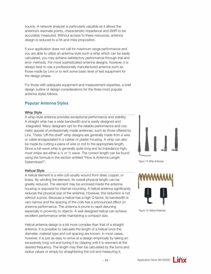
Whip StyleA whip-style antenna provides exceptional performance and stability. A straight whip has a wide bandwidth and is easily designed and integrated. Many designers opt for the reliable performance and cos-metic appeal of professionally made antennas, such as those offered by Linx. These “off-the-shelf” whip designs are generally made from a wire or cable encapsulated in a rubber or plastic housing. A whip can also be made by cutting a piece of wire or rod to the appropriate length.Since a full-wave whip is generally quite long and its impedance high, most whips are either a ¼ or ½ wave. The correct length can be found using the formula in the section entitled “How is Antenna Length Determined?”.
Helical StyleA helical element is a wire coil usually wound from steel, copper, orbrass. By winding the element, its overall physical length can begreatly reduced. The element may be enclosed inside the antenna housing or exposed for internal mounting. A helical antenna significantlyreduces the physical size of the antenna. However, this reduction is not without a price. Because a helical has a high Q factor, its bandwidth is very narrow and the spacing of the coils has a pronounced effect on antenna performance. The antenna is prone to rapid detuning especially in proximity to objects. A well designed helical can achieve excellent performance while maintaining a compact size.
Helical antenna design is a bit more complex than that of a straight antenna. It is possible to calculate the length of a helical once the diameter, material type and coil spacing are known. In most cases, however, it is just as easy to arrive at a design empirically by taking an excessively long coil and tuning it by clipping until it is resonant at the desired frequency. The length may then be calculated by the turns and radius values or simply by straightening the coil and measuring it.
Figure 13: Whip Antennas
Figure 14: Helical Antennas
Application Note AN-00500
– 12 –
Loop Trace StyleThe last style of antenna we will discuss is the loop trace. This style is popular in low-cost applications since it can be easily concealed and adds little to overall product cost. The element is generally printed directly onto the product’s PCB and can be made self-resonant orexternally resonated with discrete components. The actual layout is usually product-specific. Despite its cost advantages, PCB antenna styles are generally inefficient and useful only for short-rangeapplications. A loop can be very difficult to tune and match and is also sensitive to changes in layout or substrate dielectric constant. This canintroduce consistency issues into the production process. In addition, printed styles are difficult to engineer, requiring the use of expensiveequipment, including a network analyzer. An improperly designed loop will have a high SWR at the desired frequency, which can introduceinstability. For these reasons loops are generally confined to low-cost transmitter devices such as garage door openers, car alarms, etc.
Linx offers several low-cost planar and chip antenna alternatives (Figure 16) to the often-problematic “printed” antenna. These tiny antennas mount directly to a product’s PCB and provide excellent performance in light of their compact size.
Attenuating Output PowerIn order to meet Part 15 requirements, many designers attempt to attenuate their fundamental output power by shortening or lengthening the antenna to shift its point of resonant efficiency away from the fundamental. This is not usually a good idea for two reasons. First, by raising the SWR and reducing an antenna’s efficiency at your intendedfundamental frequency you have potentially increased the output efficiency at a harmonic. Second, by creating such a mismatch, the RF stage may become unstable. Some Linx products allow power levels to adjusted via programming or an external resistor. In other cases, an attenuation T-pad should be used as described in Linx ApplicationNote AN-00150.
Putting It All TogetherIn the design process, the antenna should be viewed as a critical component in system performance. After reviewing this application note, we hope you have a better understanding of the basic considerations necessary to achieve optimum antenna function. At Linx, our business is to make the science of RF straightforward so you can concentrate on profitably bringing your product to market. In keeping with this objective, Linx offers a growing line of optimized antenna products. A complete listing is available on the Linx website at www.linxtechnologies.com.