AbstractWe propose a full processing pipeline to acquire anthropometric measurements from 3D measurements. The first stage of ourpipeline is a commercial point cloud scanner. In the second stage, a pre-defined body model is fitted to the captured pointcloud. We have generated one male and one female model from the SMPL library. The fitting process is based on non-rigiditerative closest point algorithm that minimizes overall energy of point distance and local stiffness energy terms. In the thirdstage, we measure multiple circumference paths on the fitted model surface and use a nonlinear regressor to provide thefinal estimates of anthropometric measurements. We scanned 194 male and 181 female subjects, and the proposed pipelineprovides mean absolute errors from 2.5 to 16.0 mm depending on the anthropometric measurement.
Keywords Anthropometric measurement · 3D body model · Non-rigid ICP
1 Introduction
Anthropometricmeasurements, such as chest andhip circum-ference or shoulder-to-shoulder distance, provide detailedinformation about the body shape. The body shape infor-mation is essential for industrial design [18], clothingdesign [8], medical sciences [16] and ergonomics [19].The measurements have traditionally been made man-ually from physical subject using a tape measure, butthe raise of online shopping and personalized tools setnew demand for computerized anthropometric measure-ments.
A standard pipeline for computerized anthropometricmeasurements is the following [3,7,10,25–27]: (1) a 2Dor 3D body scan producing a 3D point cloud or an ini-tial model, (2) fitting of a pre-defined model and (3)measurements from the fitted model. The main challengeis the step two which should provide an accurate andwatertight volumetric model of a subject so that impor-
1 Computing Sciences, Tampere University, Tampere, Finland
2 NOMO Technologies Ltd, Espoo, Finland
tant measurements can be made on the model surface.Challenges arise from different sensor modalities, posesand occluded regions. The proposed method in this workshares the main steps of the standard pipeline (Fig. 1),but instead of physiologically valid model fit, we adopt anon-rigid iterative closest point (ICP) registration betweenthe model and captured point clouds. Moreover, we do notmake anthropometric measurements directly from the fittedmodel surface, but extract a set of physiologically mean-ingful surface features (body circumferences) and use themto train a regressor that provides estimates of the physi-cal anthropometric measurements. Our main contributionsare:
– A full processing pipeline from 3D body scans to anthro-pometric measurements.
– The body model registration step using a non-rigid ICPto fit a pre-defined model to captured body scans.
– Nonlinear regression based anthropometricmeasurementestimation step from circumference based intermediatefeatures.
– A public benchmark dataset—NOMO3D—with anthro-pometric measurement ground truth.
Our pipeline is evaluated with the NOMO3D dataset of realmale and female subjects (194plus 181) forwhichweprovideaverage accuracy and percentage of subjects whose accuracyis below the thresholds in [9].
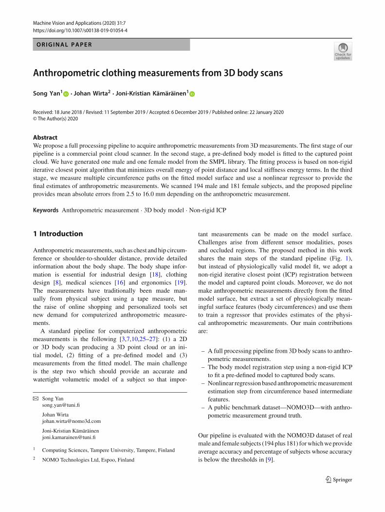
Registered meshRaw Measurement Results ti = { ti1, ti2 iC } PiC = { v1c, v2c mc}
Model Registration Surface Measurement RegressorBody Scan
f(Pi) : (t(1)i , . . . , t
(C)i ) ti
Fig. 1 The proposed pipeline for measuring anthropometric clothingmeasurements from 3D body scans. A 3D point cloud is produced bya set of depth sensors (body scanner). A body template is fitted (reg-istered) to the 3D point cloud (step-2); circumference measurements
are computed on the model surface (step-3); supervised regression isadopted to provide estimates of anthropometric measurements (step-4)
2 Related work
Anthropometric measurement datasets There have beenseveral campaigns to collect 3D body scans and anthro-pometry ground truth for them. For example, the UMTRIdataset was collected to find the safest sitting posture ofyoung children in cars [12]. ANSUR 88 (1988) and ANSUR2012 datasets contain 3D body scans and tape measuredanthropometric measurements of US Army Force soldiers.ANSUR 2012 contains 4082 male and 1986 female subjectsof varying age and 93 ground truth anthropometric measure-ments for each of them. Unfortunately, UMTRI and ANSURdatasets are not publicly available. CAESAR dataset [21] isa commercial counterpart of ANSUR and contains 3D scansof 2400 US & Canadian and 2000 European civilians withtape measured ground truth. CAESAR (http://store.sae.org/caesar/) has been used in various scientific works but hasnot been widely adopted in benchmarking due to its price.The main usage of UMTRI, ANSUR and CAESAR datasetsis to make “virtual tape measurements” on the point cloudsurface. In the follow-up work of the CAESAR, Robinetteand Daanen [20] compared virtual tape measurements overtwo different scanners and scanning teams and showed thatmeasurements are highly reproducible within the US Armydefined error limits (cf. ANSURexperiments). Reproducibil-ity error in their experiments was less than ±5 mm for themost measurements. However, these were relative accuraciesover repeated tests. Simmons and Istook [23] noted that there
is substantial variation in available softwares how to mea-sure anthropometric measurements from 3D data. Paquetteet al. [17] demonstrated much larger errors for 3D mea-surements as compared to manual tape measurements. Theyreported systematic errors of up to 30–40mmdespite the factthat standard measurement procedures were implemented tothe softwares (ISO-8559 and US Army).
3DHuman bodymodels The early works following the datacampaigns abovewere based on “virtual tapemeasurements”where the anthropometric measurements were made manu-ally with the help of 3D measurement software. If this stepneeds to be automated, then 3D scan data need to be alignedwith a model for which the measurement paths can be pre-defined using 3D model vertex ids. However, first a good 3Dhuman body model needs to be devised. The model shouldcontain intuitive parameterization for shape and pose andprovide realistic body shapes. There are several options forscientific work. The most popular parametric body model isMakeHuman which is an open source project (http://www.makehuman.org/) based on an artistic body model and aim-ing at high quality rendering for games and movies.
However, better models are based on statistics of realhuman data. These require a single artist made initial pointmodel which is iteratively matched to scanned point cloudsin a normalized pose. Principal component analysis (PCA)over the matched model points provides natural parameteri-zation for the shape. The pose can be intuitively defined by
Anthropometric clothing measurements from 3D body scans Page 3 of 11 7
a skeleton joint model, but the final quality depends on howwell the model can represent pose-specific shape deforma-tions. One of the first attempts to create a 3D human bodyfromPCA shape and skeleton pose is the SCAPEbodymodelby Anguelov et al. [2]. Hirshberg et al. [11] proposed a betterparametric bodymodel for SCAPEand introduced theBlend-SCAPE model. Other attempts are by Baek and Lee [3] andmore recently the SMPL model by Loper et al. [15]. SMPLprovides high-quality models where the shape is dividedto pose invariant and pose-dependent deformations and themodel parameters are optimized using a combination of theirown dataset of 1786 scans and 3800 scans from CAESAR.For this work, we adopt the SMPL model due to its goodoverall quality.
Computerized anthropometric measurements There havebeen several attempts to infer 3D bodymodels from 2DRGBimages. For example, Guan et al. [10] proposed amethod andcompared their measurements to the ground truth. However,for many industrial and commercial applications, the accu-racy of 2D measurements is insufficient. For better accuracy,3D scans are needed.
Weiss et al. [26] propose a Kinect-based 3D body scanmethod that uses the SCAPE body model. The methodrequires manual pose initialization and then optimizes themodel mesh using a standard ICP. Tsoli et al. [25] proposea pipeline that is similar to ours. They use the BlendSCAPEmodel to register a 3D scan, and then, they compute vari-ous local and global features which are used in regression. Adifferent approach was proposed by Zuffi et al. [32] in their“stitched puppet” model where the body model is divided tolocal templates where “local PCA” matching is performedand then the local parts are globally aligned in the next opti-mization step.Wuhrer et al. [27] introduce an inverse problemof ours where a 3D body model is estimated from the given1D anthropometric measurements.
The above works particularly address the problem ofunknown pose. However, we believe that a fixed pose canbe assumed for many applications since customers can beassumed co-operative. Therefore, the process can be drasti-cally simplified and provide accurate results.
3 3D body scanning
Recently, novel single depth sensor-based body scanningapproaches have been proposed, for example, BodyFu-sion [28] and DoubleFusion [29], but since 3D scanningis out of the scope of this work, a commercial 3D bodyscanner was used. Our dataset was collected using a com-mercial TC2 body scanner (https://www.tc2.com) that usesoff-the-shelf depth sensors (Intel RealSense R200). Insidethe scanner, subjects were instructed to step on the rotating
Fig. 2 A 3D body scan (point cloud) captured by TC2 body scanner.The scanner covers most of the body surface and missing parts occuronly in the head and feet regions
platform and take a standing pose with the feet at aroundtheir shoulder width apart and the arms slightly raised tocreate a gap between the arms and torso. The platform thenrotates around once, during which three depth sensors pro-duce a raw 3D scan of the customer, and the process takesa few seconds (Fig. 2). The test subjects wore tight fittingunderwear-like sport costumes. The scanner outputs a tri-angulated mesh structure in the regular OBJ file format.Each triangulated mesh contains on average 57,000 verticesand around 113,000 faces. For our experimental studies, wescanned 194 men and 181 women. Scanned persons wereinstructed to wear tight underwear.
4 Model registration
4.1 SMPL bodymodel
The popular 3D human body models MakeHuman, SCAPE[2],BlendSCAPE[11] andSMPL[15] (seeSect. 2 for details)share similar model parameterization {T ,S, θ} where T isthe initialmodel in a “canonical shape” and “canonical pose,”S defines the shape deformation and θ defines the pose. Poseparameterization is intuitive and typically based on a skeletonrig of K skeleton joints. A pose is encoded to the 3D rotationangles of K joints in θ . Each vertex location in T is relativeto a specific skeleton part or parts, and therefore, the wholepoint cloud deforms. Parameterization of the shape is moredifficult to model since parameters need to capture shapestatistics of the human population. The standard approach isto use principal component analysis (PCA) where principalcomponents represent the most important axes of variationin the population. In the PCA space, any shape can be recon-structed by linearly adding |β| principal directions to a meanshape T (the zero shape):
Fig. 3 We adopted the skinned multi-person linear model (SMPL) [15]for our framework since it provides intuitive model parameterizationand high-quality models. A SMPL model in its canonical (zero-pose)position (left) and the model in the initial position that corresponds tothe instructed pose in our body scans (right)
T + B(β) = T +|β|∑
n=1
βnSn . (1)
Often as few as |β| = 10, principal component vectors pro-vide sufficient accuracy for applications where subtle detailsare not important. For our work, we selected the skinnedmulti-person linear model (SMPL) by Loper et al. [15] sinceit provides very competitive accuracy and the original imple-mentation is publicly available.
SMPL mesh model contains N = 6890 vertices (13,766faces) and K = 23 skeleton joints. The mesh has the sametopology for men and women, spatially varying resolution,a clean quad structure, segmentation into parts, initial blendweights and a skeletal rig. A particular detail that makesSMPL registration more accurate than its competitors is thatit divides the shape deformation to pose-independent defor-mation BS(β) and pose-specific deformation BP(θ) whichare summed to define the final shape. Notably, the shapedeformation parameters are also used to predict the rotationsof the K = 23 skeleton joints J (β) : R
|β| → R3K . We
re-defined the SMPL zero-pose to correspond to the posesubjects were instructed to take (Fig. 3).
4.2 Non-rigid ICP registration
The goal of the body model registration to the scannedpoint cloud is to provide “skin-level registration” where thetwo surfaces, themodel and the scan, overlay almost perfectly(Fig. 4). This is a challenging task since (a) points containmeasurement noise, (b) large point regions may be missingand (c) the model points do not exactly match the scan pointlocations. To make the final anthropometric measurementsaccurate in the next processing stage, we need a registration
Fig. 4 A scanned point cloud contains holes and measurement noise,but registration of the 3D body model (red) is robust to these distortionsand achieves an accurate—“skin level”—registration which is essentialfor accurate anthropometricmeasurements in the next stage (color figureonline)
method that is accurate and robust to the aforementionednon-idealities.
A core component in constructing the SCAPE, Blend-SCAPE and SMPL datasets is an artistic-generated pointmodel and an algorithm to register the model to real humanscans.However, these algorithmsperformcomplexoptimiza-tion and must be manually initialized. Therefore, the artisticmodels and special algorithms have not been used outsidebody model generation. However, the final body models,SCAPE, BlendSCAPE and SMPL, provide intuitive param-eterization as discussed in Sect. 4.1 and registration can bedefined as an optimization problem where a few pose andshape parameters {S, θ} are optimized to minimize a regis-tration error. Skin-level registration requires a large numberof PCA components for the shape, and therefore, we take analternative approach from the generic point cloud matchingliterature.
Several comparison of generic registration methods exist.For example, Bogo et al. [4] introduced the FAUST datasetfor comparing non-rigid registration methods. In their exper-iments, several popular methods, e.g., generalized multi-dimensional scaling (GMDS) [5], Möbius voting [14] andblended intrinsic maps (BIM) [13], did not perform wellsince these methods assume that both inputs are watertightand have the same topology. However, the baseline pointcloud matching method, iterative closest point (ICP), doesnot require such assumptions.
123
Anthropometric clothing measurements from 3D body scans Page 5 of 11 7
There are two extensions of the baseline ICP that are suit-able for human body point clouds: Amberg et al. [1] andSchneider et al. [22]. Since the 3D scans often contain holes(Fig. 2),we adopted theAmberg et al. approach that explicitlyhandles missing points. The challenge is twofold—we wantto retain the global convergence properties of ICP while stillallow local deformations to the skin level. Local deforma-tions make this ICP non-rigid.
The starting point of our algorithm is a pre-aligned modeldefined by {T , βi , θk}i=1,...,|β|,k=1,...,K that brings the SMPLtemplate to approximate correspondence with the obtainedscan point cloud Tscan. A simple procedure for pre-alignmentis described in Sect. 4.3. If we define the pre-alignedmodel asV , then the problem is to find optimal values for the alignmentparameters X so that V(X ) registers the template points tothe surface points Tscan.
To solve the optimal parameters X , an energy function ofthree terms is defined [1]:
E(X ) = Ed(X ) + αEs(X ) + βEl(X ) . (2)
Ed is the standard ICP distance term between the model andscan points
Ed(X ) =∑
vi∈Vwidist
2 (Tscan,Xivi ) (3)
where Xi is a linear mapping of a single model vertex vi tocorrespondence in Tscan. wi defines whether a model pointhas a correspondence in scan (wi = 1) or not (wi = 0). Es
is a local stiffness term
Es(X ) =∑
i∈N j
‖(Xi − X j )diag(1, 1, 1, γ )‖2F (4)
where ‖·‖2F is the matrix Frobenius norm. The stiffness termenforces similar transformations between neighbor verticesN j of the model vertex v j . γ is used to weight differencesin the rotational and skew part of the deformation against thetranslations part of the deformation (γ = 1 in the experi-ments). The third energy term is a landmark term
El(X ) =∑
vi ,l∈L‖Xivi − l‖2 . (5)
The landmarks L are pre-defined and important positionsin the model and this term enforces them to be registeredaccurately. The landmark term improves registration signif-icantly, but requires manual labeling of selected keypointsand is therefore omitted in our experiments.
The algorithm in [1] uses locally affine regularizationwhich assigns an affine transformation to each vertex and
minimizes the difference in the transformation of neighbor-ing vertices. The deformation parameters X , which wouldbe applied on source vertices to generate the target surfacedeformation, are obtained by minimizing the cost functionin Eq. 6 directly and exactly.
E(X ) =∥∥∥∥∥∥
⎡
⎣αM ⊗ GWDβDL
⎤
⎦X −⎡
⎣0
WUU L
⎤
⎦
∥∥∥∥∥∥
2
F
= ‖AX − B‖2F
. (6)
The cost function E(X ) takes its minimum at X =(ATA−1)ATB. In the above equation, M is the node-arc incidence matrix of the template mesh topology, andG := diag(1, 1, 1, γ ) is a weighting matrix, W :=diag(w1, . . . , wn) represents the weighting matrix in whichwi = 0 if template vertices vi corresponds to missing datain the target mesh and n represents the number of templatevertices, D is the sparse matrix of template vertices mappingthe 4n × 3 deformation parameters X , U is the matrix of thecorrespondence points on the target mesh, DL and U L arethe pre-defined landmarks on the template mesh and theircorrespondence points on the target mesh, respectively, theKronecker product is denoted by ⊗. α and β are the penaltyterms that balance the two corresponding energy functionswith respect to the standard ICP term Ed .
The whole registration process consists of two loops.In the outer loop, a series of deformations of the tem-plate are performed for each stiffness αi ∈ {α1, . . . , αn},where αi > αi+1. These α values guarantee the registra-tion process from a global deformation to more localizedones. In our experiments, α values are set to from 100 to1 by step size 1. In the inner loop, a deformation X for afixed stiffness term αi and preliminary correspondences isfound. Preliminary correspondences are found by a nearestpoint search. The optimal deformationX is determined until||X j − X j−1|| < ε, where ε is the threshold.
4.3 Pre-alignment and initialization procedures
A simple pre-alignment procedure is performed beforenon-rigid ICP registration. Generally, the mis-alignment ofregistration is partly raised bywrong scales, face orientations,the different center points of subjects. To depreciate it, first,we scale all scans into the same unit of measurement (meter)as the SMPLmodel meshes; we then rotate all scans to makesure that they face the same direction. Compared to the pre-vious works which adopt the mean coordinate of vertices asthe center points and align all meshes into the same centerpoint, we additionally align all samples into the same lowestpoint (Z -axis). The center points change dramatically sincethe missing parts on scans and bring negative effects on reg-
123
7 Page 6 of 11 S. Yan et al.
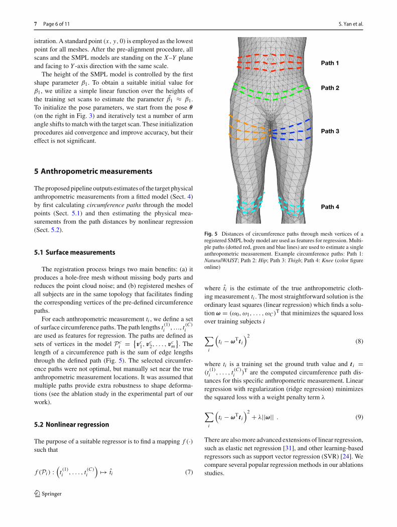
istration. A standard point (x, y, 0) is employed as the lowestpoint for all meshes. After the pre-alignment procedure, allscans and the SMPL models are standing on the X–Y planeand facing to Y -axis direction with the same scale.
The height of the SMPL model is controlled by the firstshape parameter β1. To obtain a suitable initial value forβ1, we utilize a simple linear function over the heights ofthe training set scans to estimate the parameter β1 ≈ β1.To initialize the pose parameters, we start from the pose θ
(on the right in Fig. 3) and iteratively test a number of armangle shifts to match with the target scan. These initializationprocedures aid convergence and improve accuracy, but theireffect is not significant.
5 Anthropometric measurements
Theproposedpipeline outputs estimates of the target physicalanthropometric measurements from a fitted model (Sect. 4)by first calculating circumference paths through the modelpoints (Sect. 5.1) and then estimating the physical mea-surements from the path distances by nonlinear regression(Sect. 5.2).
5.1 Surfacemeasurements
The registration process brings two main benefits: (a) itproduces a hole-free mesh without missing body parts andreduces the point cloud noise; and (b) registered meshes ofall subjects are in the same topology that facilitates findingthe corresponding vertices of the pre-defined circumferencepaths.
For each anthropometric measurement ti , we define a setof surface circumference paths. The path lengths t (1)i ,…, t (C)
iare used as features for regression. The paths are defined assets of vertices in the model Pc
i = {vc1, v
c2, . . . , v
cm
}. The
length of a circumference path is the sum of edge lengthsthrough the defined path (Fig. 5). The selected circumfer-ence paths were not optimal, but manually set near the trueanthropometric measurement locations. It was assumed thatmultiple paths provide extra robustness to shape deforma-tions (see the ablation study in the experimental part of ourwork).
5.2 Nonlinear regression
The purpose of a suitable regressor is to find a mapping f (·)such that
f (Pi ) :(t (1)i , . . . , t (C)
i
)�→ ti (7)
Path 1
Path 2
Path 3
Path 4
Fig. 5 Distances of circumference paths through mesh vertices of aregistered SMPL body model are used as features for regression. Multi-ple paths (dotted red, green and blue lines) are used to estimate a singleanthropometric measurement. Example circumference paths: Path 1:NaturalWAIST; Path 2: Hip; Path 3: Thigh; Path 4: Knee (color figureonline)
where ti is the estimate of the true anthropometric cloth-ing measurement ti . The most straightforward solution is theordinary least squares (linear regression) which finds a solu-tion ω = (ω0, ω1, . . . , ωC )T that minimizes the squared lossover training subjects i
∑
i
(ti − ωT t i
)2(8)
where ti is a training set the ground truth value and t i =(t (1)i , . . . , t (C)
i )T are the computed circumference path dis-tances for this specific anthropometric measurement. Linearregression with regularization (ridge regression) minimizesthe squared loss with a weight penalty term λ
∑
i
(ti − ωT t i
)2 + λ||ω|| . (9)
There are alsomore advanced extensions of linear regression,such as elastic net regression [31], and other learning-basedregressors such as support vector regression (SVR) [24]. Wecompare several popular regression methods in our ablationsstudies.
123
Anthropometric clothing measurements from 3D body scans Page 7 of 11 7
6 Experiments
6.1 Dataset and settings
We collected a set of 3D scans using the commercial scanner(Sect. 3). The dataset—NOMO3D—consists of 194male and181 female scans. For each subject, a clothing expert (tailor)made the actual anthropometric measurements (15 male and19 female). All results are average performance over fivefoldcross-validation.
Method evaluation We employ the mean absolute error(MAE) as the error metric between the ground truth and esti-mated anthropometricmeasurements. For eachmeasurementi , mean absolute error εi , over all subjects j was obtained as
εi = 1
| j || j |∑
j=1
∣∣∣t ( j)i − t ( j)i
∣∣∣ . (10)
In addition to themeasurement-specificMAEs, we also com-puted the averageMAEs over allmeasures.All numbersweremeasured in millimeters (mm). Moreover, for each measure-ment, we also report the proportion of the test samples forwhich the accuracy was below the defined error limits in [9]as Success rate.
Computational complexity The most time-consuming partis the non-rigid ICP registration. Matlab code was adaptedfrom [1] and it runs approximately 2min on each scan. Thepre-alignment and initialization procedures are very fast, lessthan a second, as well as the regression which is also com-putationally fast.
6.2 Results
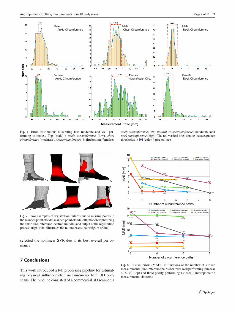
The average fivefold errors for each anthropometric mea-surement and their accuracy thresholds and success rates areshown inTable 1. In all cases, the number of surfacemeasure-ments were optimized for each anthropometric measurementand the best performing regressor (nonlinear SVR) was used.For the both male and female subjects the best performingmeasurement was neck circumference with 93% test casesbelow the threshold (6 mm) for men and 81% for women.The worst performing measure was ankle circumference forwhich only 28% of male 24% of female success rates wereachieved.The error distributions for themale and female neckand ankle circumferences and male chest and female naturalwaist circumferences are shown in Fig. 6. The distributionsreveal that there exists a small amount of test samples witha large error. It turned out that the main source of large esti-
mation errors yields from the body scanner that often missescertain body parts. For example, feet regions often lack pointcloud pointswhichmakes the registration fail in these regions(Fig. 7).
6.3 Ablation study
Number of circumference paths In the first ablationstudy, we investigated the effect of adding multiple surfacemeasurements (circumference paths) to the anthropometricregression. The results for three well and three poorly per-forming measurements for the both male and female areshown in Fig. 8. Results are for nonlinear SVR regressorwith fivefold cross-validation. The most important findingsare that additional paths always improve the accuracy anddepending on the measurement the results saturate at 3–9 surface circumference paths. In particular, paths close tothe physical anthropometric measurement location stronglycontribute to the estimation accuracy. The best single paths(C = 1) were also selected using cross-validation and theresultswith andwithout SVRregression are shown inTable 1.These results indicate that (i) the multi-path regression issuperior to single path regression and (ii) SVR significantlyimproves the estimation performance.
Non-rigid ICP To validate the importance of non-rigid ICP,we conducted an experiment where the SMPL model wasdirectly fitted to the point clouds. SMPL parameter optimiza-tion was done using the popular L-BFGS-B optimizer [30].Similar to the non-rigid ICP, the distance term Ed with thenormal direction constraints was used as the target function.The stop criterion was set to 10−6 to keep the computationtimes reasonable, and the same pre-alignment procedure wasadopted. The results are shown inTable 1 and are clearly infe-rior to the proposed non-rigid ICP registration.
Regression methods We compared a number of publiclyavailable regression methods for the regression step. Thestandard linear regressors were linear regression, stepwiselinear regression and ridge regression, and more recentregression methods are elastic net linear regression, Gaus-sian process regression (GPR), binary regression decisiontree (BRDT), linear support vector regression (SVR) andNonlinear SVR. The mean accuracy and success rates forthese methods are shown in Table 2. The results showthat even the basic linear regressors (linear regression,ridge regression and stepwise linear regression) performwell indicating that the proposed registration step performswell. Nonlinear SVR and Gaussian process regression alsoperformwell. They are all safe choices for regressing anthro-pometric measurements from surface measurements, but we
123
7 Page 8 of 11 S. Yan et al.
Table 1 Average fivefold (80% for training and 20% for testing) performance (mean absolute error) and success rate (a proportion of the testsamples within the error limits in [9]) of anthropometric measurements
Measure Best single (C = 1) Best single+SVR L-BFGS-B+SVR Multiple paths+SVR Limit [9]
MAE (mm) % MAE (mm) % C MAE (mm) % C MAE (mm) % (mm)
Bold denote the best result among several methods“C” denotes the number of circumference paths used in estimation. “best single” is the best single path performance. ”+SVR” uses SVR regressionfor the estimates. “L-BFGS-B+SVR” uses the SMPL model fitted by the L-BFGS-B optimizer
123
Anthropometric clothing measurements from 3D body scans Page 9 of 11 7
Measurement Error [mm]
Num
ber
sMale : Ankle Circumference
Male : Neck Circumference
Male : Chest Circumference
Female : Ankle Circumference
Female : Neck Circumference
Female : NaturalWaist Circ.
Fig. 6 Error distributions illustrating low, moderate and well per-forming estimates. Top (male) : ankle circumference (low), chestcircumference (moderate), neck circumference (high); bottom (female) :
ankle circumference (low), natural waist circumference (moderate) andneck circumference (high). The red vertical lines denote the acceptancethresholds in [9] (color figure online)
Fig. 7 Two examples of registration failures due to missing points inthe scanned point clouds: scanned point cloud (left),model emphasizingthe ankle circumference location (middle) and output of the registrationprocess (right) that illustrates the failure cases (color figure online)
selected the nonlinear SVR due to its best overall perfor-mance.
7 Conclusions
This work introduced a full processing pipeline for estimat-ing physical anthropometric measurements from 3D bodyscans. The pipeline consisted of a commercial 3D scanner, a
Fig. 8 Test set errors (MAEs) as functions of the number of surfacemeasurements (circumference paths) for threewell performing (success> 50%) (top) and three poorly performing (< 50%) anthropometricmeasurements (bottom)
123
7 Page 10 of 11 S. Yan et al.
Table 2 Average MAEs and success rates of several regression methods
Non-lin SVR Ridge reg. Lin reg. Stepw. reg. GPR ElasticNet BRDT Lin SVR
deformable SMPL body model, non-rigid ICP-based modelregistration, computation of circumference path featuresand nonlinear regression for anthropometric measurementestimation.Depending on themeasurement, our pipeline pro-vided success rates from 28% to 93% for male and from 24to 82% for female subjects. The proposed pipeline works inpractice and shows that an affordable scanning system canbe built for clothing industry.
In the future work, we will further investigate and refineeach step of the pipeline. For example, selection of bettersurface features in addition to the circumference paths, fast-to-compute alternatives for the slow ICPalgorithm (e.g.Chenet al. [6]) and better scanners and scanning procedures.
Open Access This article is licensed under a Creative CommonsAttribution 4.0 International License, which permits use, sharing, adap-tation, distribution and reproduction in any medium or format, aslong as you give appropriate credit to the original author(s) and thesource, provide a link to the Creative Commons licence, and indi-cate if changes were made. The images or other third party materialin this article are included in the article’s Creative Commons licence,unless indicated otherwise in a credit line to the material. If materialis not included in the article’s Creative Commons licence and yourintended use is not permitted by statutory regulation or exceeds thepermitted use, youwill need to obtain permission directly from the copy-right holder. To view a copy of this licence, visit http://creativecommons.org/licenses/by/4.0/.
References
1. Amberg, B., Romdhani, S., Vetter, T.: Optimal step nonrigid ICPalgorithms for surface registration. In: CVPR (2007)
2. Anguelov, D., Srinivasan, P., Koller, D., Thrun, S., Rodgers, J.,Davis, J.: SCAPE: shape completion and animation of people. In:SIGGRAPH (2005)
7. Chen, Y., Robertson, D.P., Cipolla, R.: A practical system for mod-elling body shapes from single view measurements. In: BMVC(2011)
8. Daanen, H., Hong, S.A.: Made-to-measure pattern developmentbased on 3D whole body scans. Int. J. Cloth. Sci. Technol. 20(1),15–25 (2008)
9. Gordon, C.C., Churchill, T., Clauser, C.E., Bradtmiller, B.,McConville, J.T., Tebbetts, I., Walker, R.A.: Anthropometric sur-vey of us army personnel: summary statistics, interim reportfor 1988. Tech. rep, Anthropology Research Project Inc, YellowSprings, OH (1989)
10. Guan, P., Weiss, A., Balan, A.O., Black, M.J.: Estimating humanshape and pose from a single image. In: ICCV (2009)
11. Hirshberg, D.A., Loper, M., Rachlin, E., Black, M.J.: Coregistra-tion: simultaneous alignment andmodeling of articulated 3Dshape.In: ECCV (2012)
12. Kim, K., Jones, M., Ebert, S., Malik, L., Manary, M., Reed, M.,Klinich, K.: Development of virtual toddler fit models for childsafety restraint design. Tech. Rep. UMTRI-2015-38, University ofMichigan Transportation Research Institute (2015)
13. Kim, V., Lipman, Y., Funkhouser, T.: Blended intrinsic maps. In:SIGGRAPH (2011)
14. Lipman, Y., Funkhouser, T.: Möbius voting for surface correspon-dence. In: SIGGRAPH (2009)
15. Loper, M., Mahmood, N., Romero, J., Pons-Moll, G., Black, M.J.:SMPL: a skinned multi-person linear model. ACM Trans. Graph.(Proc. SIGGRAPH Asia) 34(6), 248:1–248:16 (2015)
16. Ogden, C., Fryar, C., Carroll, M., Flegal, K.: Mean body weight,height, and body mass index, United States 1960–2002. Examina-tion Surveys 347, Division of Health and Nutrition (2004)
17. Paquette, S., Brantley, J.D., Corner, B.D., Li, P., Oliver, T.: Auto-mated extraction of anthropometric data from 3D images. In:Proceedings of theHumanFactors andErgonomics SocietyAnnualMeeting, vol. 44, pp. 727–730. SAGE Publications, Los Angeles(2000)
18. Park, B.K.D., Ebert, S., Reed, M.: A parametric model of childbody shape in seated postures. Traffic Inj. Prev. 18(5), 533–536(2017)
19. Pheasant, S., Haslegrave, C.: Bodyspace: Anthropometry,Ergonomics and the Design of Work, 3rd edn. Taylor & Francis,New York (2005)
20. Robinette, K., Daanen, H.: Precision of the CAESAR scan-extracted measurements. Appl. Ergon. 37, 259–265 (2006)
21. Robinette, K.M., Blackwell, S., Daanen, H., Boehmer, M., Flem-ing, S.: Civilian American and European surface anthropometryresource (CAESAR) final report. Tech. Rep. AFRL-HE-WP-TR-2002-0169, US Air Force Research Laboratory (2002)
22. Schneider, D.C., Eisert, P.: Fast nonrigid mesh registration with adata-driven deformation prior. In: ICCV Workshop (2009)
23. Simmons, K., Istook, C.: Body measurement techniques: compar-ing 3D body-scanning and anthropometric methods for apparelapplications. J. Fash. Mark. Manag. Int. J. 7, 306–332 (2003)
24. Vladimir, V., Golowich, S.E., Smola, A.J.: Support vector methodfor function approximation, regression estimation and signal pro-cessing. In: Proceedings of the 9th International Conference onNeural Information Processing, pp. 281–287 (1997)
31. Zou, H., Hastie, T.: Regularization and variable selection via theelastic net. J. R. Stat. Soc. 67, 301–320 (2005)
32. Zuffi, S., Black, M.: The stitched puppet: a graphical model of 3Dhuman shape and pose. In: CVPR (2015)
Publisher’s Note Springer Nature remains neutral with regard to juris-dictional claims in published maps and institutional affiliations.
Song Yan is a second-year PhD student at Department of Comput-ing, Tampere University, under the supervision of Associate ProfessorJoni-Kristian Kämäräinen at the Computer Vision Group. He receivedBE degree from Department of Software Engineering, Sichuan Uni-versity, in June 2015 and masters degree from Department of Infor-mation Technology, Communication Systems and Networks, TampereUniversity of Technology, in August 2017. As an enthusiasticresearcher, his goal is to combine state-of-the-art deep learning algo-rithms with real-life industrial problems. He is currently solving prob-lems of human body reconstruction, pose and shape estimation.
JohanWirta is the CEO and Founder of NOMO Technologies Ltd whohas 12 years of experience in various positions in the retail businessand 10 years of international experience. He participated in severalinformation system development projects.
Joni-Kristian Kämäräinen is an associate professor at Computing Sci-ences Department at Tampere University where he is part of the VisionGroup. He did his post-doc in Center of Vision, Speech and SignalProcessing, University of Surrey, with Josef Kittler. After the post-doc,he spent five years in the Faculty of the LUT School of EngineeringScience, LUT University, after which he was selected to the currenttenure-track position in 2012.