1
CXT/800
Anti-Collision and Zone Protection System for Tower Cranes
Instructions for Installation & Operation
CHENGDU HI-TECH CRANE SAFETY CO., LTD.
Add.: CI/13F, Diamond Building, No. 36, East Linjiang Road, Chengdu, China
Tel.: 86 28 85483791 85483792 85483793
Fax: 86 28 85483795
Zip Code: 610021
Http: www.cranesafety-china.com
E-mail: [email protected]
2
CONTENT
I CXT/800 System Purpose…………………………………………………………………………………….1
II System Composition & Basic Purpose……………………………………………………………………..2
III CXT/800 Anti-collision System Characteristics……………………………………………………………3
IV How CXT/800 System Performs the Anti-collision Functions……………………………………………4
V Zone Protection & Fixed Obstacle Anti-collision……………………………………………………………7
VI Divided Zone Protection…………………………………………………………………………………….. 8
VII Single System Composition……………………………………………………………………………….. 9
VIII Central Control/Data Input System Composition & Graphic Representation………………………..13
IX CXT/800 System Hardware Installation………………………………………………………………….. 14
X Data Input, Install, Wireless Upload & Adjustment of CXT/800 System………………………………..15
XI Notice of Operation CXT/800 System……………………………………………………………………..25
XII System Maintenance……………………………………………………………………………………..25
XIII Fault Analysis & Remedies……………………………………………………………………………..26
XIV Technical Support & Service…………………………………………………………………………...27
3
I CXT/800 System Purpose
How to prevent the risk of collision in crane “interference” areas and inhibit over-flying of sensitive areas
such as streets, highways, schools, public areas and power lines is the noticeable safety problem in the
construction field, which will be brought into the strict construction safety management gradually. The
relevant regulations and standards thereby have been made for guaranteeing the safety in construction.
However, it is unavoidable that such accidents as interference and over- flying have happened. There are
some reasons as follows:
1. Just paying more attention to the heavy loads, the operator may overlook controlling the position of the
tower cranes nearby before he starts to operate the tower crane.
2. The operator hardly sees the counter-jib of the tower crane he operates.
3. The operator can’t see the fine sling of other tower crane entering into his working scope due to the strong
sunshine.
4. The operator may be wrong in judging the distance between the jib head (some is up to 80M) and other
tower crane or building.
5. The operator seldom notices some protection zones outside the construction projects.
So how to deal with the above-mentioned problems is brought into the construction agenda.
The main purpose of this system is to control and deal with construction on-site problems simultaneously by
computer: interference between tower cranes in a multi-crane site and the protection of prohibited zones. The
system can provide real-time supervision and monitoring for up to 20 tower cranes in one single site, as well
as saving records in case of tracking and checking.
The system contributes to productivity on site by allowing operators to work at maximum safe speed and
optimizing the use of cranes. It continuously calculates the relative locations of jib-arms and trolleys of the
tower crane within the network that might interfere with each other. Upon detecting that there are possibilities
of tower cranes interfering or even colliding with another one or the tower crane hook(or jib) overstepping
into the prohibited “sensitive”(protected)zones, such as streets, highways, schools, public areas, and power
lines, the system will give pre-alarm first till the operating system of the tower crane works and stop the
operation, thus keep the possibilities of accidents from happening due to negligence or misjudgment by the
operator and guaranteeing safe operation of the tower crane.
Note: CXT/800 anti-collision and zone protection system is only an auxiliary controlling device. It can
provide useful operation information for tower cranes, and it can brake safely if necessary, but it can’t
directly replace commands from the operator.
4
II System Composition & Basic Purpose
The whole system mainly consists of two parts.
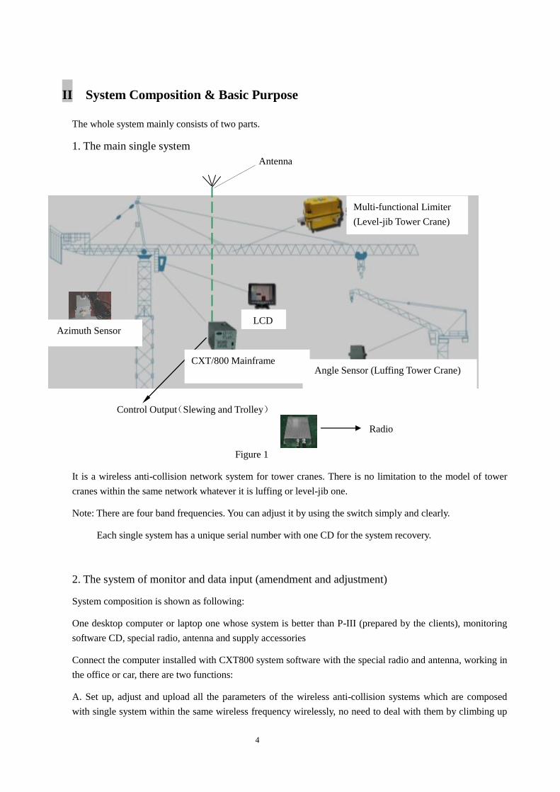
1. The main single system
The above-mentioned main single system with the same wireless band frequency on one single site
Figure 1
It is a wireless anti-collision network system for tower cranes. There is no limitation to the model of tower
cranes within the same network whatever it is luffing or level-jib one.
Note: There are four band frequencies. You can adjust it by using the switch simply and clearly.
Each single system has a unique serial number with one CD for the system recovery.
2. The system of monitor and data input (amendment and adjustment)
System composition is shown as following:
One desktop computer or laptop one whose system is better than P-III (prepared by the clients), monitoring
software CD, special radio, antenna and supply accessories
Connect the computer installed with CXT800 system software with the special radio and antenna, working in
the office or car, there are two functions:
A. Set up, adjust and upload all the parameters of the wireless anti-collision systems which are composed
with single system within the same wireless frequency wirelessly, no need to deal with them by climbing up
Control Output(Slewing and Trolley)
Antenna
Multi-functional Limiter
(Level-jib Tower Crane)
9
9
Angle Sensor (Luffing Tower Crane) CXT/800 Mainframe
Azimuth Sensor
Radio
LCD
5
the tower crane.
The parameters are shown as below:
XY coordinate points (showing construction site range) ; the distributing series numbers of the tower cranes
on site; corresponding single system series numbers; XY coordinate values, height, max/min hook amplitude,
counter-jib length, anti-collision data of each tower crane etc.
When the system is in normal running, if one of the tower cranes needs to rise, the system can manage the
height amendment and upload it wirelessly.
Another tower crane can be added to this working network or taken off from the network.
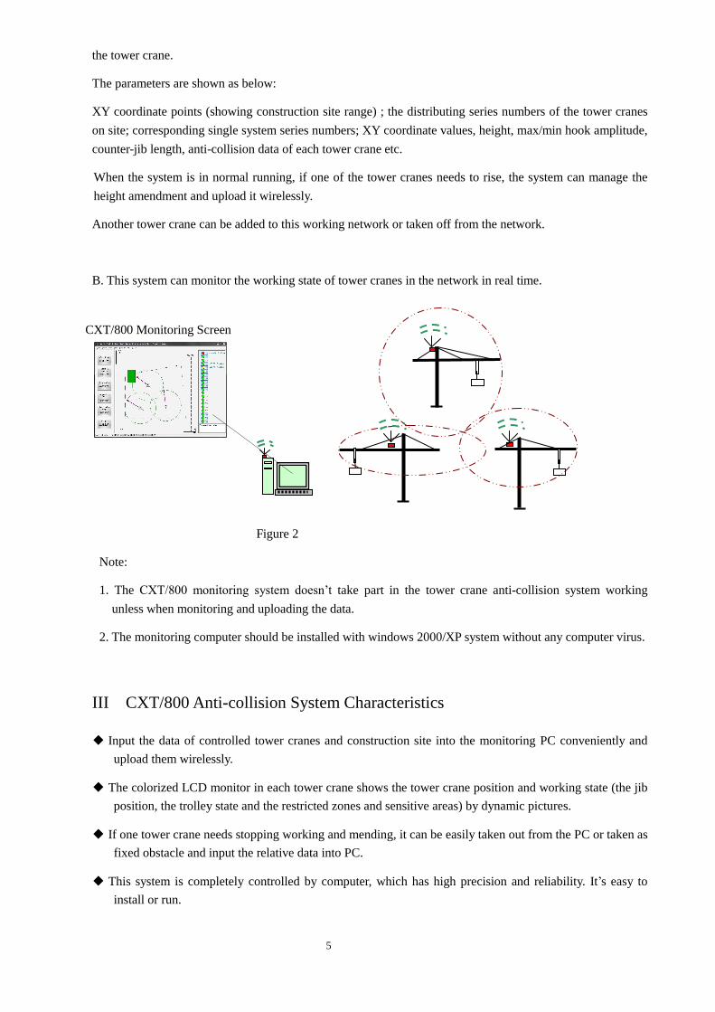
B. This system can monitor the working state of tower cranes in the network in real time.
Figure 2
Note:
1. The CXT/800 monitoring system doesn’t take part in the tower crane anti-collision system working
unless when monitoring and uploading the data.
2. The monitoring computer should be installed with windows 2000/XP system without any computer virus.
III CXT/800 Anti-collision System Characteristics
◆ Input the data of controlled tower cranes and construction site into the monitoring PC conveniently and
upload them wirelessly.
◆ The colorized LCD monitor in each tower crane shows the tower crane position and working state (the jib
position, the trolley state and the restricted zones and sensitive areas) by dynamic pictures.
◆ If one tower crane needs stopping working and mending, it can be easily taken out from the PC or taken as
fixed obstacle and input the relative data into PC.
◆ This system is completely controlled by computer, which has high precision and reliability. It’s easy to
install or run.
CXT/800 Monitoring Screen
6
◆ The single system keeps permanent anti-collision records for checking
◆ It adapts to different tower cranes by changing the single anti-collision parameters.
IV How CXT/800 System Performs the Anti-collision Functions
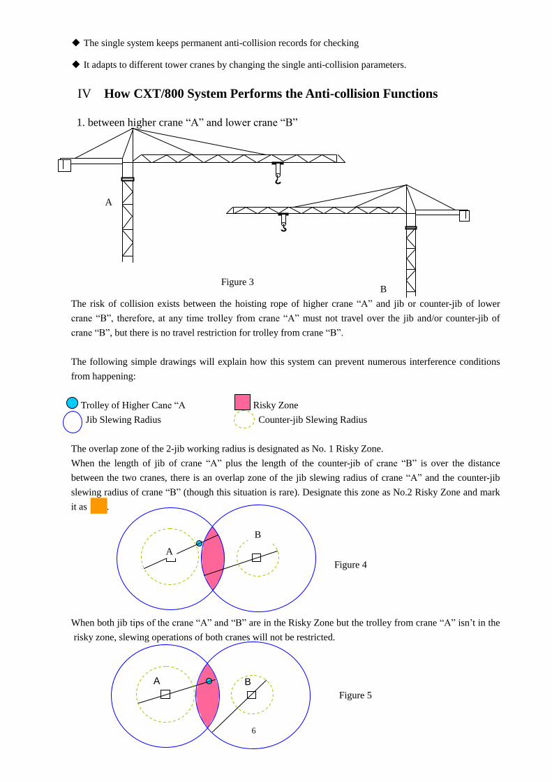
1. between higher crane “A” and lower crane “B”
A
B
The risk of collision exists between the hoisting rope of higher crane “A” and jib or counter-jib of lower
crane “B”, therefore, at any time trolley from crane “A” must not travel over the jib and/or counter-jib of
crane “B”, but there is no travel restriction for trolley from crane “B”.
The following simple drawings will explain how this system can prevent numerous interference conditions
from happening:
Trolley of Higher Cane “A Risky Zone
Jib Slewing Radius Counter-jib Slewing Radius
The overlap zone of the 2-jib working radius is designated as No. 1 Risky Zone.
When the length of jib of crane “A” plus the length of the counter-jib of crane “B” is over the distance
between the two cranes, there is an overlap zone of the jib slewing radius of crane “A” and the counter-jib
slewing radius of crane “B” (though this situation is rare). Designate this zone as No.2 Risky Zone and mark
it as .
Figure 4
When both jib tips of the crane “A” and “B” are in the Risky Zone but the trolley from crane “A” isn’t in the
risky zone, slewing operations of both cranes will not be restricted.
Figure 5
Figure 3
A B
A
B
7
When the trolley of crane “A” and the jib of crane “B” approach or enter into the Risky Zone, the system will
automatically start calculating the distance between the trolley of crane “A” and the jib of crane “B”. When
the distance reaches the pre-set Safety Value, the system will alarm and restrict the slewing operation. If
necessary, it will automatically trigger the slewing braking mechanism.
Figure 6
When the jib from crane “A” and jib from crane “B” overlap and the trolley of crane “A” is approaching the
crossing point , the system will automatically restrict trolley of crane “A” moving outward(Figure 5)and
inwards (Figure 6). It will simultaneously restrict jib of crane “B” moving leftward (Figure 6) and rightward
(Figure 7).
Figure 4 to Figure7 show No.1 Risky Zone only.
Figure 8 and Figure 9 indicate there is a circumstance of No.2 Risky Zone existing, restrictions to No.1 Risky
Zone wills the same which is shown in Figure 4 to Figure 7.
Figure 7
When the counter-jib tip of the crane “B” enters No.2 Risky Zone first, this Risky Zone immediately becomes
the Prohibited Zone where the trolley of crane “A” cannot enter (either restricting its moving outward and/or
restricting the slewing of the second slewing angle of crane “A”).
Figure 8
When the trolley of crane “A” enters No. 2 Risky Zone first, this Risky Zone immediately becomes the
Prohibited Zone where the counter-jib of crane “B” cannot enter (restricting the slewing of the second
slewing angle of crane “B”).
A B A B
A B
A B
8
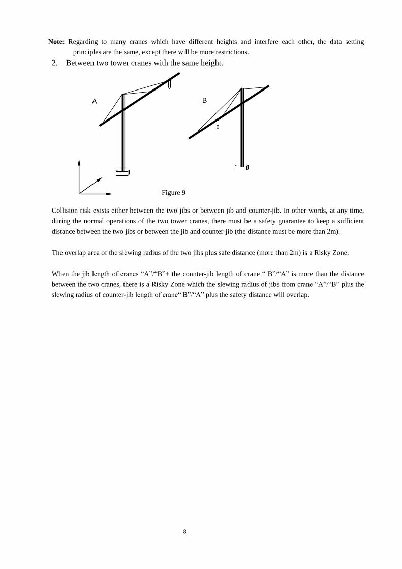
Note: Regarding to many cranes which have different heights and interfere each other, the data setting
principles are the same, except there will be more restrictions.
2. Between two tower cranes with the same height.
Collision risk exists either between the two jibs or between jib and counter-jib. In other words, at any time,
during the normal operations of the two tower cranes, there must be a safety guarantee to keep a sufficient
distance between the two jibs or between the jib and counter-jib (the distance must be more than 2m).
The overlap area of the slewing radius of the two jibs plus safe distance (more than 2m) is a Risky Zone.
When the jib length of cranes “A”/“B”+ the counter-jib length of crane “ B”/“A” is more than the distance
between the two cranes, there is a Risky Zone which the slewing radius of jibs from crane “A”/“B” plus the
slewing radius of counter-jib length of crane“ B”/“A” plus the safety distance will overlap.
A B
Figure 9
9
The pre-set minimum acceptable safe distance for system to alarm and reduce speed can be amended based on
the actual parameter of the jib length and the slewing speed (the default value is respectively 20m and 10m).
This system has the functions of judging the jib slewing distance, pre-alarming and speed reducing
automatically.
The possible collision risk will happen between the jib and the counter-jib, shown as above, and about the
preventive measures, please refer to above too.
Note: the height difference between two tower cranes is not more than 10m (including 10m), the system will
judge it as the same height.
V Zone Protection & Fixed Obstacle Anti-collision
Zone protection means preventing hook (or jib) from flying over sensitive (protected) zones, such as streets,
roads, highways, school, public areas, railway tracks, power lines. Fixed obstacles mean the existing fixed
objects with certain height at construction site. After installing CXT/800 system on site, input the parameters
at initial setting. These parameters are data from several turning points of the protected zones (they may form
several close zones) that constitute on-site axis values(X1, Y1), inputting the height data of fixed obstacles
which should be higher than tower crane.
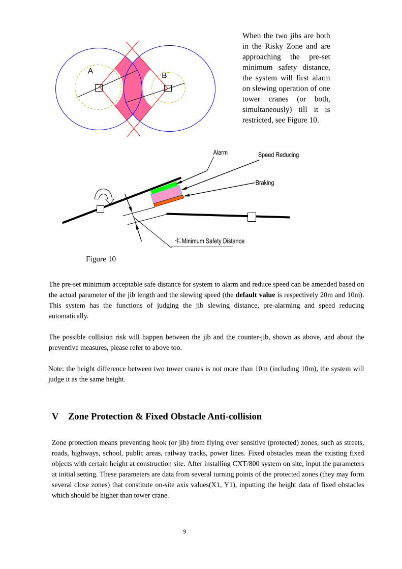
A B
Alarm Speed Reducing
Braking
≮Minimum Safety Distance
Figure 10
When the two jibs are both
in the Risky Zone and are
approaching the pre-set
minimum safety distance,
the system will first alarm
on slewing operation of one
tower cranes (or both,
simultaneously) till it is
restricted, see Figure 10.
10
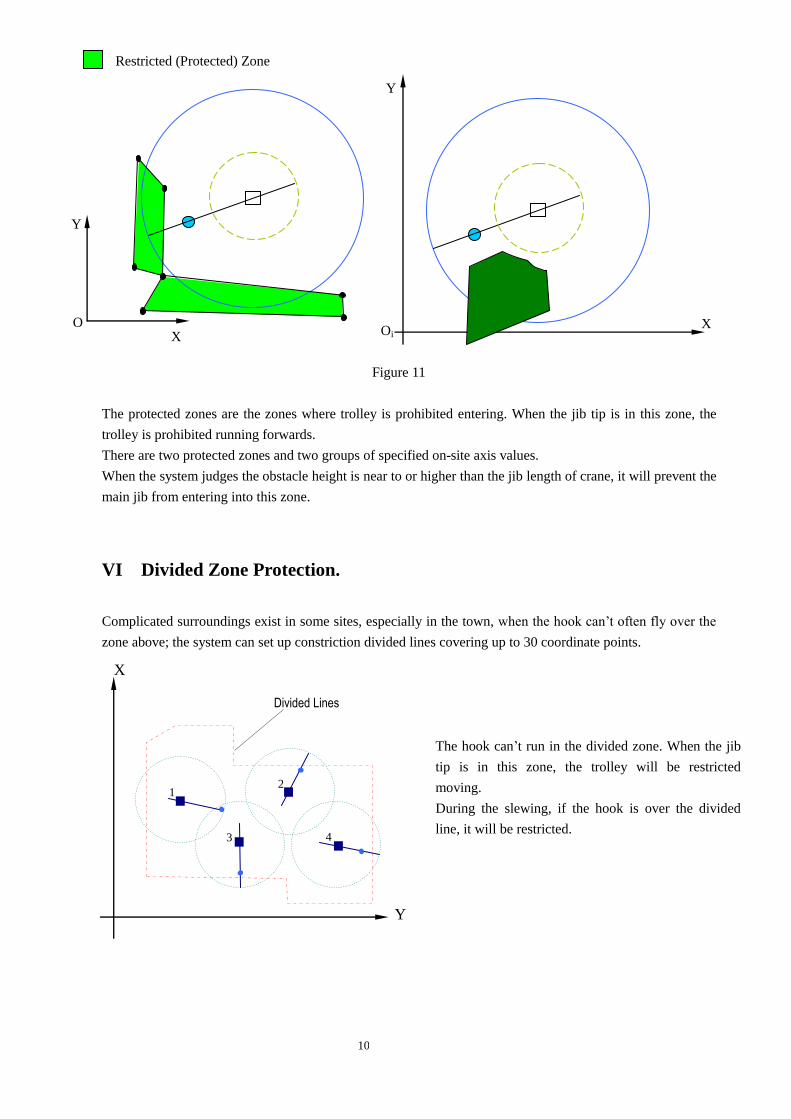
Restricted (Protected) Zone
Figure 11
The protected zones are the zones where trolley is prohibited entering. When the jib tip is in this zone, the
trolley is prohibited running forwards.
There are two protected zones and two groups of specified on-site axis values.
When the system judges the obstacle height is near to or higher than the jib length of crane, it will prevent the
main jib from entering into this zone.
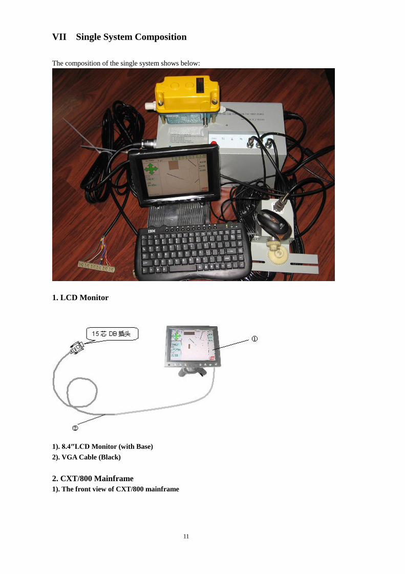
VI Divided Zone Protection.
Complicated surroundings exist in some sites, especially in the town, when the hook can’t often fly over the
zone above; the system can set up constriction divided lines covering up to 30 coordinate points.
X
Y
Oi
The hook can’t run in the divided zone. When the jib
tip is in this zone, the trolley will be restricted
moving.
During the slewing, if the hook is over the divided
line, it will be restricted.
1 2
3 4
X
Y
Divided Lines
O
Y
X
11
VII Single System Composition
The composition of the single system shows below:
1. LCD Monitor
1). 8.4″LCD Monitor (with Base)
2). VGA Cable (Black)
2. CXT/800 Mainframe
1). The front view of CXT/800 mainframe
12
2). The side view of the CXT/800 mainframe
Relay Running Indicator Light
Control Output Interface 1
Control Output Interface 2
Slewing Setting Switch
Amplitude Setting Switch
USB Interface
Power Switch Slewing Signal Input (7-Pin)
Radius Signal Input (5-Pin)
VGA Plug
Power Plug
Wireless
Data Input
(5-Pin)
System Running Indicator Light
13
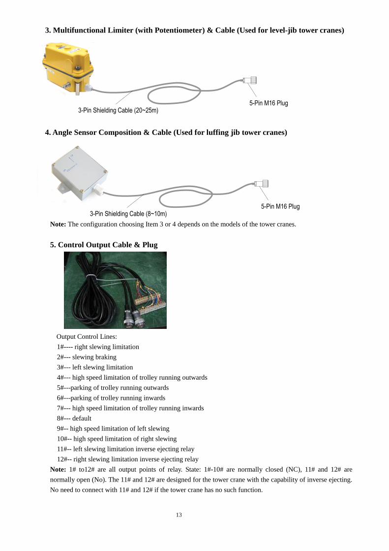
3. Multifunctional Limiter (with Potentiometer) & Cable (Used for level-jib tower cranes)
4. Angle Sensor Composition & Cable (Used for luffing jib tower cranes)
For luffing tower crane
Note: The configuration choosing Item 3 or 4 depends on the models of the tower cranes.
5. Control Output Cable & Plug
Output Control Lines:
1#---- right slewing limitation
2#--- slewing braking
3#--- left slewing limitation
4#--- high speed limitation of trolley running outwards
5#---parking of trolley running outwards
6#---parking of trolley running inwards
7#--- high speed limitation of trolley running inwards
8#--- default
9#-- high speed limitation of left slewing
10#-- high speed limitation of right slewing
11#-- left slewing limitation inverse ejecting relay
12#-- right slewing limitation inverse ejecting relay
Note: 1# to12# are all output points of relay. State: 1#-10# are normally closed (NC), 11# and 12# are
normally open (No). The 11# and 12# are designed for the tower crane with the capability of inverse ejecting.
No need to connect with 11# and 12# if the tower crane has no such function.
5-Pin M16 Plug 3-Pin Shielding Cable (20~25m)
5-Pin M16 Plug
3-Pin Shielding Cable (8~10m)
14
The slewing braking mode of the default system is braking when power-off while adjustment of the wire end
is needed if slewing mode of the tower crane is braking by power supply
6. Wireless Data Transmission Radio
7. Antenna & Feeder
8. Slewing Angle Sensor
15
9. The Accessories for the System
One system recovery CD with a unique serial number
One photoelectric mouse with USB interface
One keyboard with USB interface
VIII Central Control/Data Input System Composition & Graphic Representation
1. Computer: desktop or laptop one (the clients prepare it by themselves)
2. CXT/800 System Monitoring CD
3. Wireless Data Transmission Radio
4. Antenna & Feeder
5. Radio Data Wire & USB TO RS232 Adaptor
6. Radio AC220/DC12V Power Adapter
16
7. The Switch Lines Supported by Auto DC12V
8. USB Disc Driver
Note: It’s used for CXT800/800 single system recovery if necessary
IX CXT/800 System Hardware Installation
Note: It must not connect the plug into the mainframe socket before finishing the complete installation.
This mainframe series numbers and the tower crane number should be in line with the preparative
materials, see” tower crane setup”
For example: 2# tower crane corresponds to No.C8015, make sure C8015 mainframe is connected
with 2# while installation.
1. Mainframe Installation
Put the mainframe into the driver’s cabin of the tower crane in a proper position. Keep dry.
2. LCD Monitor Installation
1). Put the LCD monitor base into the driver’s cabin of the tower crane in a proper position.
2). Insert the VGA cable into the plug at the side.
3. Antenna Assembly & Radio Installation
1). Connect the antenna with the feeder and tighten it, then use a clip to fix the antenna on the top of driver’s
cabin outside, and then lead the feeder into the cabin, inserting the plug into the antenna port which lies in
the right position of the radio and screwing it down.
2). Put the radio into the driver’s cabin.
3). Insert the 5-pin plug into the plug port which lies in the left of radio and screw it down.
4). Insert the other end of 5-pin plug into the wireless data plug port which lies in the mainframe and screen it
down.
4. Installation of Limiters & Cable (for level-jib tower cranes)
1). Take down the original trolley travel limiter of tower crane, and replace the CXT800-3 limiter provided
with the system. The electrician will finish connecting the relative control wires.
2). Lead the cable of limiter into the cabin along the main jib’s top mechanism, then connect the 5-pin plug
with the radius signal socket marked with in the mainframe, and then screw it down.
Remark: If the original limiter size of tower crane is not in line with that of CXT800-3, clients can change
and install it on the spot according to the actual trolley mechanism conditions.
5. Installation of Angle Sensor Composition & Cable (for luffing tower cranes)
1). Choose the proper position on the left side of the main jib tip mechanism, drill 2-M5 hole according to the
holes on the angle sensor shell on the spot, fix the shell here, see the Figure as following:
17
2). Lead the cable of angle sensor into the cabin, then connect the 5-pin plug with the radius signal socket
marked as in the mainframe and then screw it down.
6. Slewing Angle Sensor Installation.
1). Connect the rotary axis of the slewing travel limiter and the rotary axis of the slewing angle sensor
(CXT800-8) by gear.
2). Lead the cable of slewing angle sensor into the cabin, then connect the 7-pin plug with the radius signal
socket marked as in the mainframe, and then screw it down.
Remark: If the original limiter size of tower crane is not in line with that of CXT800-8, clients can change
and install it on the spot according to the actual slewing mechanism conditions, making sure the slewing of
tower crane is accordance with the slewing angle sensor.
7. Inspection
Check all installation accessories, cables and power access etc., making sure it is right, then run the CXT/800
system automatically by pressing the power on/off button, observing the LCD screen, it is ok if there is data
behind “ ” “ ” ,turn it off after finishing checking.
X Data Input, Install, Wireless Upload & Adjustment of CXT/800 System
1.Preparation
1). Compile on-site fundamental parameters
A. Confirmation of coordinate system on site: According to the detailed drawing of construction, set up X
and Y axis on coordinate system, rectangular scope on site has four coordinate values (X1,Y1) (X2,Y2)
(X3,Y3) (X4,Y4), Y axis on coordinate system is relative to deflection angle of N direction of north magnetic
pole on earth ( clockwise is “+” while anti-clockwise is”_”).
B. Actual quantity of tower cranes needing to install with CXT/800 system on site and the numbers, numbers
can only be chosen between 1~20, the number are not allowed to repeated in the same site. For example, if
there are five sets. They can be named 1, 2, 3, 4, 5; it can also named 1, 3, 5, 6, 8.
C. The corresponding coordinates (Xi, Yi) for the numbered tower cranes, types of tower crane (level-jib or
luffing), the fundamental parameter of tower crane: level-jib tower crane-----height(the main jib or counte-
jib), minimum amplitude, maximal amplitude, length of counter-jib; luffing tower crane----height(of
counter-jib ), maximal amplitude, maximal/minimum elevation of the jib, length of counter-jib、structural
parameter a0 (distance between main jib and the slewing center)
2—M5 bolt fixed
Jib arrow mark
points to the jib tip
along the main jib.
18
D. Check whether there is data of protection area and dividing line or not
E. Pre-set the parameters of unified anti-collision and control data
2). Install the central monitoring/data input system software
We suggest installing the software in the laptop computer, which is suitable for working on site or in the car.
And the computer system shall be Win2000/XP.
A. Software installation
a. Insert the USB/RS232 adaptor into the USB interface of the computer;
b. Install the drive system of USB/RS232 adaptor;
c. Install the CXT/800 system monitoring program.
B. Data input
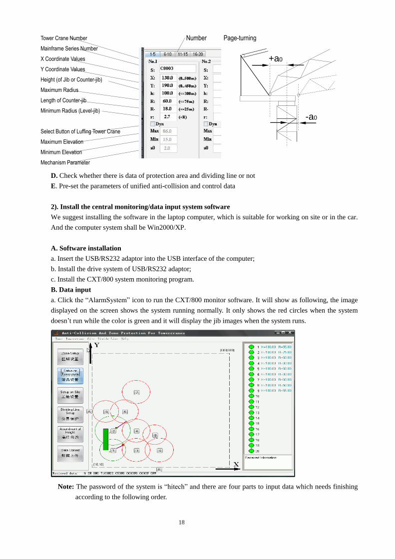
a. Click the “AlarmSystem” icon to run the CXT/800 monitor software. It will show as following, the image
displayed on the screen shows the system running normally. It only shows the red circles when the system
doesn’t run while the color is green and it will display the jib images when the system runs.
Note: The password of the system is “hitech” and there are four parts to input data which needs finishing
according to the following order.
Tower Crane Number
Mainframe Series Number
X Coordinate Values
Y Coordinate Values
Height (of Jib or Counter-jib)
Maximum Radius
Length of Counter-jib
Minimum Radius (Level-jib)
Select Button of Luffing Tower Crane
Maximum Elevation
Minimum Elevation
Mechanism Parameter
Number Page-turning
r page turing
+a0
-a0
19
1) 2)
3) 4)
1) and 2) are the most important parts, making sure all the data are correct. You can set up the 3)and 4)when
necessary, they can exist at the same time.
b. Setup on site: Click , Site window pops up, then click Modify, there is a small
window of Password, input “hitech”, and then click OK.
Procedure interface and parameter meaning show below:
Input and amend the data according to the prepared on-site parameters, then click OK.
Note: The reference points of slewing calibration are coordinates when the slewing angle sensor begins to
calibrate.
c. Setup on tower crane: click , Setup on Towercrane window pops up, then click Modify,
a small window of Password comes up, input “hitech”, then click OK, and then input or amend the data of
tower cranes.
Setup on Site
工地设置
Setup on Tower crane
塔吊设置
Zone Setup
区域设置
Dividing Line Setup
分界保护
Setup on Site
工地设置
XY Coordinate Values of Four Points on Rectangle of
Construction Site
Deflection angle from coordinate axis Y to earth N
Trolley Stop Low-speed Distance
Trolley Stop High-peed Distance
Distance of Slewing
Brarking
Distance of Slewing
Parking
Distance of Slewing
Pre-alarm
Inertia Angle
Setup on Tower crane
塔吊设置
20
Prepare the mainframe according to actual need on site; plan, arrange and record the information on which
the tower crane numbers are in line with mainframe series number, input data one by one, then confirm by
clicking OK.
Note: If it is luffing tower crane, data of “r” may be not input, it is necessary to input the next three items
after clicking of “Dyn” button.
d. Zone setup: If there are protected zones or obstacles on site, this setting is needed. Click “ ”
button, input “Password”, then input the data according to the inflexion coordinate of actual zones. The system
can support setting up of ten zones, which will be displayed with color on interface.
Note: The parameter “H” is height value of zone which has to be input. A smaller value can be input in the
protected zones while a bigger value is needed to input in the obstacles (bigger than the height of tower crane).
e. Divided line setup: It’s necessary to set up divided line if there are too many protected zones (the hook can’t
over cross), which are shown as dashed lines on the interface. Click “ ” button, input
“Password”, then come into the window to input the data of each inflexion coordinate of boundary, then input
one by one. The last value must be the same as the first value. The system can input 30 points at most.
After finishing inputting or updating or the data on site, it’s necessary to back up all the data to prevent losing the
former data if there are more construction sites.
Method: Set up a file on the table of computer, copy the file which is in “C:\Program Files\Towercrane\DataFile\” to
it. When need it, just copy it back.
3). Preparation work before installing the mainframe on the tower cranes
Upload data of each system in the workshop before going to the construction site, complete this one by one.
a. Prepare all the parts of monitoring PC and monitoring system and connect them well, then choose the right
frequency of radio (1-4), inserting the power supply of radio (AC220V or auto DC12V), and then turn on computer
and run CXT/800 monitoring program.
Power Supply
USB Port
USB/RS232 Adaptor
Radio Data Wire
Radio
Zone Setup
区域设置
Dividing Line Setup
分界保护
21
b. Take a mainframe which is well-prepared, choose the right frequency of radio, connect it with the monitor
(azimuth and radius signal plugs may not be connected), then connect the mainframe power supply (AC200V), and
then press “Power” button to turn on (startup/shut down) CXT/800 system. Several minutes later, it comes into a
stable system working interface automatically, waiting for the data uploading;
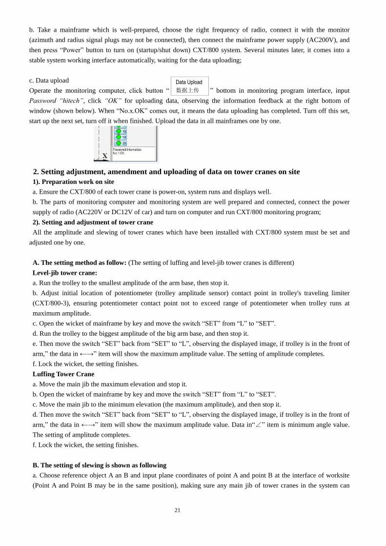
c. Data upload
Operate the monitoring computer, click button “ ” bottom in monitoring program interface, input
Password “hitech”, click “OK” for uploading data, observing the information feedback at the right bottom of
window (shown below). When “No.x.OK” comes out, it means the data uploading has completed. Turn off this set,
start up the next set, turn off it when finished. Upload the data in all mainframes one by one.
2. Setting adjustment, amendment and uploading of data on tower cranes on site
1). Preparation work on site
a. Ensure the CXT/800 of each tower crane is power-on, system runs and displays well.
b. The parts of monitoring computer and monitoring system are well prepared and connected, connect the power
supply of radio (AC220V or DC12V of car) and turn on computer and run CXT/800 monitoring program;
2). Setting and adjustment of tower crane
All the amplitude and slewing of tower cranes which have been installed with CXT/800 system must be set and
adjusted one by one.
A. The setting method as follow: (The setting of luffing and level-jib tower cranes is different)
Level-jib tower crane:
a. Run the trolley to the smallest amplitude of the arm base, then stop it.
b. Adjust initial location of potentiometer (trolley amplitude sensor) contact point in trolley's traveling limiter
(CXT/800-3), ensuring potentiometer contact point not to exceed range of potentiometer when trolley runs at
maximum amplitude.
c. Open the wicket of mainframe by key and move the switch “SET” from “L” to “SET”.
d. Run the trolley to the biggest amplitude of the big arm base, and then stop it.
e. Then move the switch “SET” back from “SET” to “L”, observing the displayed image, if trolley is in the front of
arm,” the data in ←→” item will show the maximum amplitude value. The setting of amplitude completes.
f. Lock the wicket, the setting finishes.
Luffing Tower Crane
a. Move the main jib the maximum elevation and stop it.
b. Open the wicket of mainframe by key and move the switch “SET” from “L” to “SET”.
c. Move the main jib to the minimum elevation (the maximum amplitude), and then stop it.
d. Then move the switch “SET” back from “SET” to “L”, observing the displayed image, if trolley is in the front of
arm,” the data in ←→” item will show the maximum amplitude value. Data in“∠” item is minimum angle value.
The setting of amplitude completes.
f. Lock the wicket, the setting finishes.
B. The setting of slewing is shown as following
a. Choose reference object A an B and input plane coordinates of point A and point B at the interface of worksite
(Point A and Point B may be in the same position), making sure any main jib of tower cranes in the system can
Data Upload
数据上传
22
move from A to B anti-clockwise. It is suggested to choose any two points which are 1 meter far from the tower
crane. If the tower crane can not rotate 360°, the point A and point B should be separated.
b. Point the main jib directly to point A.
c. Open the wicket of mainframe by key and move the switch “SET” from “R” to “SET”.
d. Rotate the main jib directly to point A anti-clockwise.
e. Then move the switch “SET” back from “SET” to “R”, observing the displayed image, the main jib should point
to point B directly. If it is, the slewing setting is ok.
f. Lock the wicket, the setting finishes.
Note: The keyboard settings will be introduced later, but we sincerely advise to set the parameters by using the
above-mentioned methods.
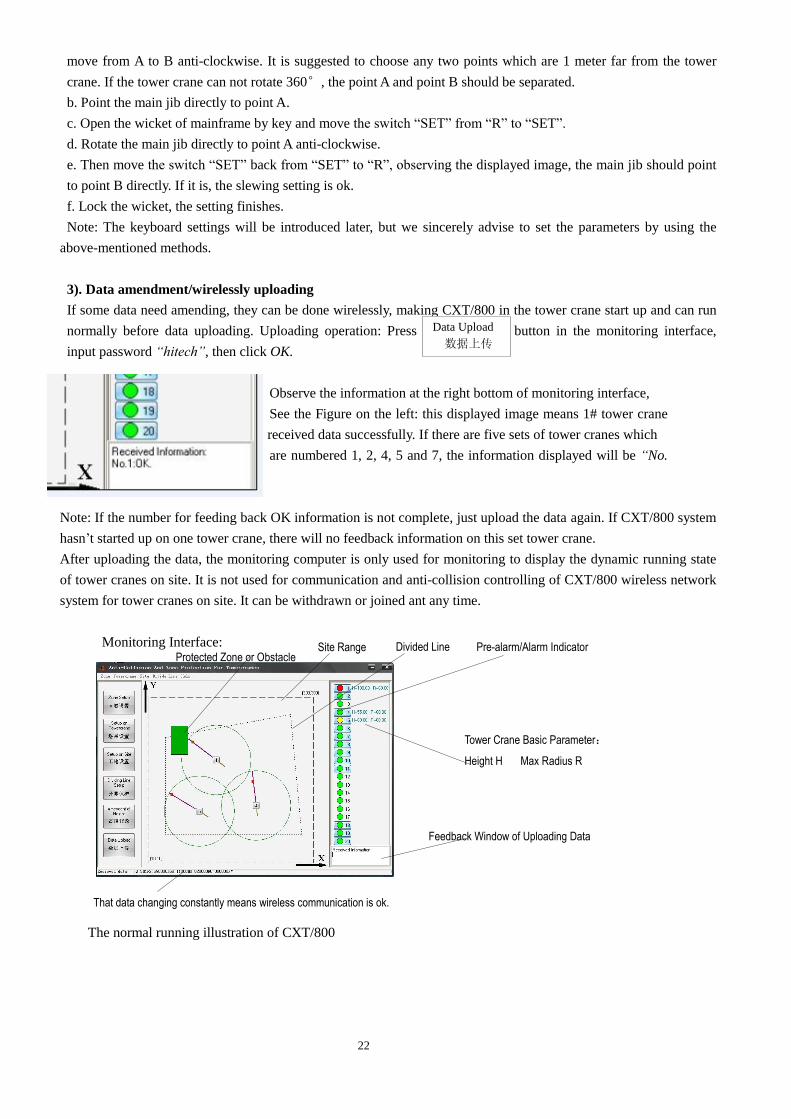
3). Data amendment/wirelessly uploading
If some data need amending, they can be done wirelessly, making CXT/800 in the tower crane start up and can run
normally before data uploading. Uploading operation: Press button in the monitoring interface,
input password “hitech”, then click OK.
Observe the information at the right bottom of monitoring interface,
See the Figure on the left: this displayed image means 1# tower crane
has received data successfully. If there are five sets of tower cranes which
are numbered 1, 2, 4, 5 and 7, the information displayed will be “No.
1.2.4.5.7.OK “.
Note: If the number for feeding back OK information is not complete, just upload the data again. If CXT/800 system
hasn’t started up on one tower crane, there will no feedback information on this set tower crane.
After uploading the data, the monitoring computer is only used for monitoring to display the dynamic running state
of tower cranes on site. It is not used for communication and anti-collision controlling of CXT/800 wireless network
system for tower cranes on site. It can be withdrawn or joined ant any time.
Monitoring Interface:
The normal running illustration of CXT/800
Data Upload
数据上传
Protected Zone or Obstacle Site Range Divided Line
Tower Crane Basic Parameter:
Height H Max Radius R
Pre-alarm/Alarm Indicator
Feedback Window of Uploading Data
That data changing constantly means wireless communication is ok.
23
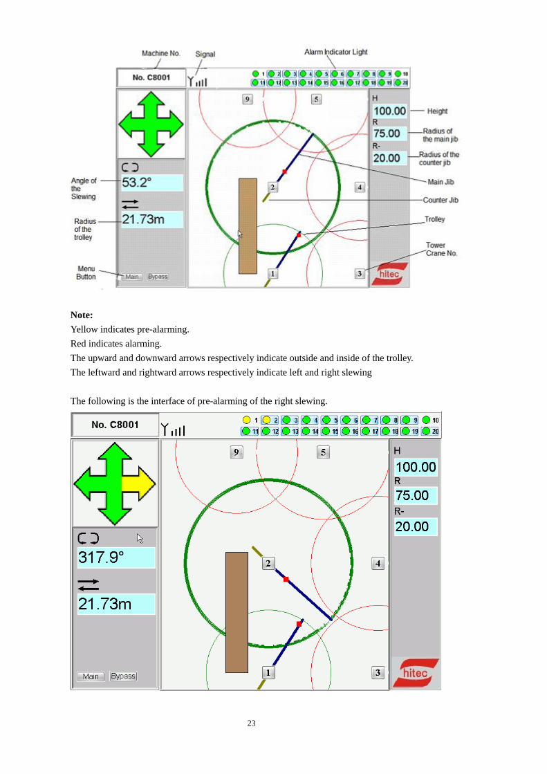
Note:
Yellow indicates pre-alarming.
Red indicates alarming.
The upward and downward arrows respectively indicate outside and inside of the trolley.
The leftward and rightward arrows respectively indicate left and right slewing
The following is the interface of pre-alarming of the right slewing.
24
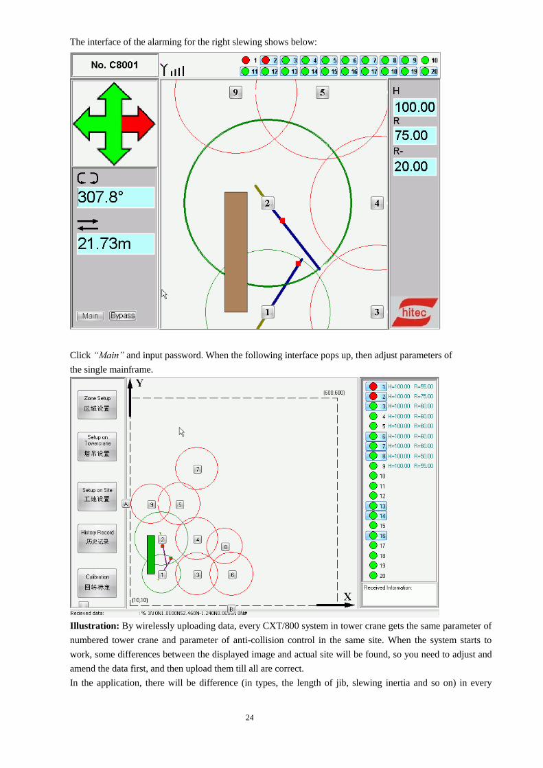
The interface of the alarming for the right slewing shows below:
Click “Main” and input password. When the following interface pops up, then adjust parameters of
the single mainframe.
Illustration: By wirelessly uploading data, every CXT/800 system in tower crane gets the same parameter of
numbered tower crane and parameter of anti-collision control in the same site. When the system starts to
work, some differences between the displayed image and actual site will be found, so you need to adjust and
amend the data first, and then upload them till all are correct.
In the application, there will be difference (in types, the length of jib, slewing inertia and so on) in every
25
tower crane, the uniform parameter of anti-collision control is not suitable, especially when luffing crane and
level-jib crane are used in the same site, so anti-collision parameter of some tower cranes need setting up
respectively. CXT/800 system has this function, but it can not perform the function by wireless uploading
(the same parameter), it needs setting-up one bye one
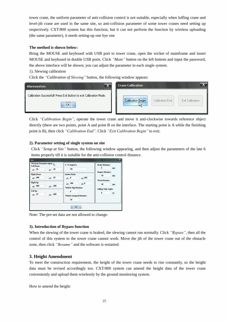
The method is shown below:
Bring the MOUSE and keyboard with USB port to tower crane, open the wicket of mainframe and insert
MOUSE and keyboard in double USB ports. Click “Main” button on the left bottom and input the password,
the above interface will be shown; you can adjust the parameter in each single system.
1). Slewing calibration
Click the “Calibration of Slewing” button, the following window appears
Click “Calibration Begin”, operate the tower crane and move it anti-clockwise towards reference object
directly (there are two points, point A and point B on the interface. The starting point is A while the finishing
point is B), then click “Calibration End”. Click “Exit Calibration Begin” to exit.
2). Parameter setting of single system on site
Click “Setup at Site” button, the following window appearing, and then adjust the parameters of the late 6
items properly till it is suitable for the anti-collision control distance.
Note: The pre-set data are not allowed to change.
3). Introduction of Bypass function
When the slewing of the tower crane is braked, the slewing cannot run normally. Click “Bypass”, then all the
control of this system to the tower crane cannot work. Move the jib of the tower crane out of the obstacle
zone, then click “Resume” and the software is restarted.
3. Height Amendment
To meet the construction requirement, the height of the tower crane needs to rise constantly, so the height
data must be revised accordingly too. CXT/800 system can amend the height data of the tower crane
conveniently and upload them wirelessly by the ground monitoring system.
How to amend the height:
26
Press button on the monitoring interface, it pops up the following window.
Click “Password’ button, import “hitech”, and then click OK, it will pop up the following window.
Note: When amending the height, make sure all CXT/800 system must run normally, otherwise it will not
display “OK” information on the interface.
4. Operation
After all the date have been input, set and adjusted, the system can be operated normally. The button of turn
on/off is the same one which locates besides the antenna socket at the bottom of the mainframe, marked as
red “Power” bottom; meanwhile, it is a power indicator light.
Any tower crane can join the network or withdraw from it anytime, which won’t affect the other systems
working state, however, it should avoid that some systems withdraw at the same time, or it will cause the
confusion of network and the system will halt, then you have to restart system.
The working state of system can be observed from the monitoring computer. The red circle indicates the
offline system and there is no image of jib of tower crane, while green circle indicate the online sytem.
5. Check the alarming record of the system
Connect mainframe with mouse, click “Main” button at the left bottom of the interface, press“ →” and then
click menu of “History” item, the alarming record window pops up, you can check all the records which
are saved permanently in the system.
Amendment of Height
高度修改
Choose the worksite number which
needs to amend height of tower crane.
Figure on the left shows 1# tower crane,
input the needed height data; confirm it
is ok, hen click Modify to upload. It will
show OK window if it finishes, then click
Close to exit, and then backup the data.
27
XI Notice of Operation CXT/800 System
1. The computer which installed in supervisory control system can’t bear any virus.
2. Exit the system in thunderstorm weather, pull out antenna plug and pull out the plug of mainframe to
prevent lightning.
3. Don’t start the system before the cable of monitor and mainframe box are not connected well, or it will be
turned black screen.
4. Select different radio frequency range when the systems are used at the same time apart in 5km.
5. The monitor and the mainframe can’t get wet and get sweat, keep the screen away from the hard thing in
case of damage.
6. The operators of the tower crane must start and exit the system in time normally when on duty.
7. The communication of the system adapts to mainframe mode. The first turned on is the mainframe, and the
mainframe is not allowed to power off during the work time, otherwise the communication won’t work.
XII System Maintenance
1. Mainframe and Monitor
●Often check the fixation and connection between mainframe and monitor. Keep them firm, stable and free
of loose status.
●Regularly check power supply cable whether is broken or the sheath is damaged. Check if the connection
is firm and stable on the grounding.
●Check if the lead-out cable, plugs and sockets are loose. Do not insert or draw the cable improperly, or it
may cause poor contact.
●Do not clean the panel with chemical solvent. Wipe it with semi-wet towel.
●Keep the mainframe and monitor from rain and avoid exposing to sunlight directly.
●Do not open the rear cover of case randomly.
2. Signal Cables and Sensors:
●Regularly check arrangement of all sensor cables to avoid occurrence of crushing, bending or damage at
some locations.
●Regularly check if installation of the azimuth sensor base is firm and if its shell installation is ok.
●Make sure the installation of trolley limiter (angle sensor) fixed is firm.
28
XIII Fault Analysis & Remedies
Faults Reasons Methods
Mainframe doesn’t work
after power-on
Power line is broken Check the circuit and connection of
mainframe.
Fault is caused by
power supply of
mainframe
Contact manufacturer.
Mainframe can start up but
the indicator of monitor is
off.
Monitor disconnects
with mainframe.
1. Reconnect them firmly.
2. Connect keyboard, then press
Ctrl + Alt + F1 , displaying in 3 sec.
Mainframe can start up and
the indicator of monitor is
on, but monitor is in black.
Poor connection
between monitor and
mainframe.
Same as above.
Displayed data changes
unstably or screening down.
Poor connection of
grounding or it is
broken.
Check the grounding circuit, making sure
it is connected reliably.
Radius data changes too
big or too small, the
trolley’s position changes
abnormally in image.
Haven’t set up radius
data. Set up radius data
Radius data doesn’t change. Signal transmission
ends.
Check signal cable and plug.
Check the connection in the mainframe.
Check the connection between trolley
limiter and rotary axis.
Azimuth data doesn’t
change or it is zero, the
image doesn’t change when
slewing.
No signal inputs. Check the connection of signal cable and
plug, making sure they connect well.
Azimuth sensor is
broken. Contact manufacturer
Mainframe can start up and
the monitor can display, but
the system cannot run
normally.
Mainframe system
software is damaged
or the relative
software is damaged.
Use recovery disc of CXT/800 system to
recover the system, making sure the
series number must be line with that of
the recovery disc.
1. Connect driver and keyboard with
mainframe.
2. Put recovery disc into the mainframe,
choose disc startup item, it will recover
the system automatically, and then take
out the disc.
3. Restart the mainframe,re-upload and
reset all the data.
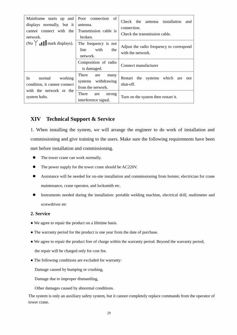
29
Mainframe starts up and
displays normally, but it
cannot connect with the
network.
(No mark displays).
Poor connection of
antenna.
Transmission cable is
broken.
Check the antenna installation and
connection.
Check the transmission cable.
The frequency is not
line with the
network.
Adjust the radio frequency to correspond
with the network.
Composition of radio
is damaged. Connect manufacturer
In normal working
condition, it cannot connect
with the network or the
system halts.
There are many
systems withdrawing
from the network.
Restart the systems which are not
shut-off.
There are strong
interference signal. Turn on the system then restart it.
XIV Technical Support & Service
1. When installing the system, we will arrange the engineer to do work of installation and
commissioning and give training to the users. Make sure the following requirements have been
met before installation and commissioning.
The tower crane can work normally.
The power supply for the tower crane should be AC220V.
Assistance will be needed for on-site installation and commissioning from hoister, electrician for crane
maintenance, crane operator, and locksmith etc.
Instruments needed during the installation: portable welding machine, electrical drill, multimeter and
screwdriver etc
2. Service
● We agree to repair the product on a lifetime basis.
● The warranty period for the product is one year from the date of purchase.
● We agree to repair the product free of charge within the warranty period. Beyond the warranty period,
the repair will be charged only for cost fee.
● The following conditions are excluded for warranty:
Damage caused by bumping or crushing,
Damage due to improper dismantling,
Other damages caused by abnormal conditions.
The system is only an auxiliary safety system, but it cannot completely replace commands from the operator of
tower crane.