Page 1
40 | P a g e
ANTI COLLISION ENHANCEMENT OF SHA-1 USING
AES ENCRYPTION
Nalina H D1, Shruthi T M
2, Spoorthi .Y
3, Thilagavathy R
4
1,3, 4Electronics & Communication, GSSSIETW Mysuru,(India)
2Electronics & Communication, GMIT Mandya, (India)
ABSTRACT
The SHA-1 hash function used in many fields of security system such as digital Signature, tamper detection,
password protection and so on.SHA-1 is very important algorithm for integrity and authentication
realization,SHA-1 is a one way algorithm to Produce hash code of any message with 160 random hash bits,
which cannot be reversible. AES with SHA-1 algorithm produce encrypted code that can be reversible to
achieve confidentiality.
From the implementation and simulation results of AES based on SHA-1 algorithm obtained in VHDL project
show simplicity in modeling hash function algorithm generating hash codes encrypted by AES method.
Keywords—Secure Hash Algorithm (SHA), Advanced Encryption Standard (AES), S-Box
(Substitute Box)
I. INTRODUCTION
Security has become an increasingly important feature with the growth of electronic communication. The
Symmetric in which the same key value is used in both the encryption and decryption calculations are becoming
more popular. The AES algorithm is capable of using cryptographic keys of 128, 192, and 256 bits to encrypt
and decrypt data in blocks of 128 bits. This standard is based on the Rijndael algorithm. The SHA-1 and AES
implemented by using VHDL, first the original message is processed via SHA-1 algorithm then the code
generated by SHA-1 is processed via AES algorithm to give a Very secure code that cannot be breakable easily.
AES the hash function itself is not achieve confidentiality, just obtain authentication and integrity. To make the
hash more secure there is a need to merge the hash code that produced with any encryption method.
The AES algorithm is implemented in VHDL to realize the confidentiality property to support the security of the
system. The original message that processed by SHA-1 algorithm first, represent the plaintext. The hash code
that produced via SHA-1 represents the key or the password of AES algorithm to generate another code which is
very difficult to break the original message entered to SHA-1 to pass under the whole system operations to give
SHA1 data which represent the hash code. This code then enters to AES encryption block to give the cipher text.
The cipher text which is generated from the encrypted hash by AES then entered to AES decryption block to
return the plaintext which is the original message. Nowadays cryptography has a main role in embedded systems
design. As the number of devices and applications which send and receive data are increasing rapidly, the data
Page 2
41 | P a g e
transfer rates are becoming higher. In many applications, this data requires a secured connection which is
usually achieved by cryptography. Cryptography is divided in two categories first is symmetric key
cryptography (sender and receiver shares the same key) and the second one is asymmetric key cryptography
(sender and receiver shares different keys). Here we are concerned about symmetric key cryptography due to its
use in military application, embedded system design, financial and legal files, medical reports, and bank services
via Internet, telephone conversations, and e-commerce transactions etc. Many symmetric key cryptographic
algorithms were proposed, such as the Data Encryption Standard (DES), the Elliptic Curve Cryptography
(ECC), the Advanced Encryption Standard (AES) and other algorithms.
The National Institute of Standards and Technology (NIST) has initiated a process to develop a Federal
information Processing Standard (FIPS) for the Advanced Encryption Standard (AES), specifying an Advanced
Encryption Algorithm to replace the Data Encryption standard(DES) the Expired in 1998. The Rijndael
Algorithm was chosen since it had the best overall scores in security, performance, efficiency, implementation
ability and flexibility. The Rijndael algorithm is a symmetric block cipher that can process data blocks of 128
bits through the use of cipher keys with lengths of 128, 192, and 256 bits. The AES algorithm as Rijndael is also
a symmetric block cipher that can encrypt (encipher) and decrypt (decipher) information. Encryption converts
data to an unintelligible form called cipher text. Decryption of the cipher-text converts thedata back into its
original form, which is called plaintext. The number of rounds is depends upon the key length.
II. RELATED WORKS AND CONTRIBUTIONS
The AES algorithm implemented in VHDL to realize the confidentiality property to support the security of the
system. The original message that processed by SHA-1 algorithm first, represent the plaintext. The hash code
that produced via SHA-1 represents the key or the password of AES algorithm to generate another code which is
very difficult to break. The SHA-1 and AES implemented by using VHDL , first the original message is
processed via SHA-1 algorithm then the code generated by SHA-1 is processed via AES algorithm to give a
very secure code that cannot be breakable easily.
A) SHA-1 Algorithm
Fig 1 shows the steps involved in the SHA-1 Algorithm
Page 3
42 | P a g e
The algorithm processing includes the following steps
Padding
Appending Length
Process message in 16-word blocks
Initializing the SHA-1 buffer
Padding
The purpose of message padding is to make the total length of a padded message congruent to 448 modulo
512(length = 448 mod 512). The number of padding bits should be between 1 and 512. Padding consists of
single 1-bit followed by the necessary number of 0-bits.
Given an m-bit message, a single bit 1 is appended as the m + 1th bit and then (448 (m + 1)) mod 512 (between
0 and 511) zero bits are appended. As a result, the message becomes 64-bit short of being a multiple of 512 bits
long.
Appending Length
A 64-bits binary representation of the original length of the message is appended to the end of the message.
Initializing the SHA-1 buffer
The 160-bits buffer is represented by five four-word buffers (A, B, C,D, and E) used to store the middle or final
results of the message digest for SHA-I functions. They are initialized to the following values in hexadecimal.
Low-order bytes are put first.
The result is divided into 512-bit blocks, denoted by M1, M2, M3`.The internal state of SHA-1 is composed of
five 32-bit words A, B, C, D and E, used to keep the 160-bit chaining value high.
Word A: 67 45 23 01;
Word B: EF CD AB 89;
Word C: 98 BA DC EF;
Word D: 10 32 54 16;
Word E: C3 D2 El F0;
Process message in 16-word blocks
The heart of the algorithm is a module that consists of four rounds of processing 20 steps each. The four rounds
have a similar structure, but each uses a different primitive logical function. These logical functions are defined
as follows
These rounds take as input the current 512-bits block and the 160-bits buffer value (A, B, C, D, E), and then
update these buffers.
F (t; B, C, D) = (B AND C) OR ((NOT B) AND D) (0 <= t <= 19);
F (t; B, C, D) = B XOR C XOR D (20 <= t <= 39);
F (t; B, C, D) = (B AND C) OR (B AND D) OR (C AND D) (40 <= t
<= 59);
Page 4
43 | P a g e
F (t; B, C, D) = B XOR C XOR D (60 <= t <= 79).
Each round also makes use of an additive constant K (t). In hex the
values are shown below.
K (t) = 5A827999 (0 <= t <= 19);
K (t) = 6ED9EBA1 (20 <= t <= 39);
K (t) = 8F1BBCDC (40 <= t <= 59);
K (t) = CA62C1D6 (60 <= t <= 79);
II. AES Algorithm
The Encryption process of Advanced Encryption Standard algorithm is presented below, in Figure 2. This block
diagram is generic for AES specifications. It consists of a number of different transformations applied
consecutively over the data block bits, in a fixed number of iterations, called rounds. The number of rounds
depends on the length of the key used for the encryption process.
Figure 2: AES Algorithm
Page 5
44 | P a g e
AES Algorithm consists of following steps
Sub Bytes
Shift Rows
Mix Columns
Add Round key
Sub Bytes
The bytes substitution transformation Byte sub (state) is a non-linear substitution of bytes that operates
independently on each byte of the State using a substitution table (Sbox) presented in figure 3.
Figure 3: Application of S-box to the Each Byte of the State
The Substitute bytes stage uses an S-box to perform a byte-by-byte substitution of the block. There is a single
8-bit wide S-box used on every byte. This S-box is a permutation of all 256 8-bit values, constructed using a
transformation which treats the values as polynomials in however it is fixed.
The each byte of the state is replaced by byte indexed by row and column. The S-box used in the Sub Bytes
transformation is presented in hexadecimal Called an s-box. This matrix consists of all the possible
combinations of an 8 bit sequence (28= 16x16 = 256). However, the s-box is not just a random permutation of
these values and there is a well defined method for creating the s-box tables.
This S-box which is invertible, is constructed by composing two transformations
1. Take the multiplicative inverse in the finite field GF (28);
2. Apply the following affine transformation (over GF (2))
The S-box used in the Sub Bytes transformation is presented in hexadecimal form in figure 4.
Page 6
45 | P a g e
Figure 4: S-box values for all 256 combinations in hexadecimal format
For example, if =S1,1= 53, then the substitution value would be determined by the intersection of the row with
index 5 and the column with index 3 in figure 4. This would result in S'1, 1 having a value of ed.
Rijndael was designed to have the following characteristics
Resistance against all known attacks.
Speed and code compactness on a wide range of platforms.
Design Simplicity
Shift Row
In the Shift Rows transformation Shift Rows, the bytes in the last three rows of the State are cyclically shifted
over different numbers of bytes the number a row is shifted can’t be the same as shown in figure 5. The Shift
Rows stage provides a simple permutation of the data, whereas the other steps involve substitutions. Further,
since the state is treated as a block of columns, it is this step which provides for diffusion of values between
columns. It performs a circular rotate on each row of 0, 1, 2 3 places for respective rows.
It works as follows
The first row of state is not altered.
The second row is shifted 1 bytes to the left in a circular manner.
The third row is shifted 2 bytes to the left in a circular manner
The fourth row is shifted 3 bytes to the left in a circular manner
Page 7
46 | P a g e
Figure 5: shift row block
Mix Columns
This transformation is based on Galois Field multiplication. Each byte of a column is replaced with another
value that is a function of all four bytes in the given column. The Mix Columns ( ) transformation operates on
the State column-by-column, treating each column as a four-term polynomial. Each column is processed
separately. The columns are considered as polynomials over GF (28) and multiplied modulo x4 + 1 with a fixed
polynomial.
a(x) = 03x3 + 01x2 + 01x + 02.
S' (x) = a(x) S(x).
This stage (known as Mix Column) is basically a substitution but it makes use of arithmetic of GF (28). Each
column is operated on individually. Each byte of a column is mapped into a new value that is a function of all
four bytes in the column. The transformation can be determined by the following matrix multiplication on state
(see figure 6):
Each element of the product matrix is the sum of products of elements of one row and one column. In this case
the individual additions and multiplications are performed in GF (28). The Mix Columns transformation of a
single column j (0 <j<3) of state can be expressed as:
Page 8
47 | P a g e
Figure 6: Mix column block
Add Round Key
The Add Round Key stage, which likes Byte Substitution, operates on each byte of State independently as
shown in figure 7. The Add Round Key transformation is self inverting. It maps a 128-bit input state to a 128-bit
output state by XOR ing the input state with a 128-bit round key.
Figure 7: Add around key block
Figure 8: Add around key block example
Page 9
48 | P a g e
As shown in the figure 8, in this stage (known as AddRoundKey) the 128 bits of state are bitwise XORed with
the 128 bits of the round key. The operation is viewed as a column wise operation between the 4 bytes of a state
column and one word of the round key. This transformation is as simple as possible which helps in efficiency
but it also affects every bit of state. The AddRoundKey transformation is self inverting .It maps a 128-bit input
state to a 128-bit output state by XORing the input state with a 128-bit round key.
Key Schedule Generation
Each round key is a 4-word (128-bit) array generated as a product of the previous round key, a constant that
changes each round, and a series of S-Box ( figure 2) lookup values for each 32-bit word of the key. The first
round key is the same as the original user input. Each byte (w0 - w3) of initial key is XORd with a constant that
depends on the current round, and the result of the S-Box lookup for wi, to form the next round key.
The Key schedule Expansion generates a total of Nb (Nr + 1) words: the algorithm requires an initial set of Nb
words, and each of the Nr rounds requires Nb words of key data. The resulting key schedule consists of a linear
array of 4-byte words, denoted [WI], with i in the range 0 i < Nb (Nr + 1).
III. RESULTS AND DISCUSSION
From the implementation of cryptography hash function in VHDL test the execution of all steps in SHA-1
algorithm in different types of plaintext such as English, Arabic, symbols, and numbers to produce fixed 160
bits hash code. After generating of the 160 bits hash code, these bits entered to AES algorithm which is 128 bits
key to both encryption and decryption to give a very strong code which is very difficult to break. The encrypted
hash code gives the confidentiality to the data.
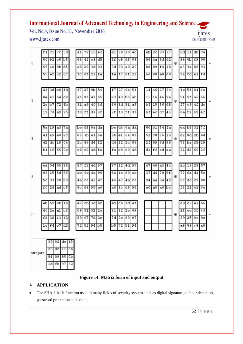
The following diagram shows the values in the State array as the Encryption Progresses for a block length and a
Key length of 16 bytes each (i.e., Nb = 4 and Nk =4).
Input = 32 43 f6 a8 88 5a 30 8d 31 31 98 a2 e0 37 07 34
Cipher Key = 2b 7e 15 16 28 ae d2 a6 ab f7 15 88 09 cf 4f 3c
Page 10
49 | P a g e
Figure 9: Create the module and open it in the editor
In the simulation process, first step is to create the project with the new HDL Module as shown in figure 9.
Figure 11; generating the constraints
Page 11
50 | P a g e
Next step is to creating constraints and generating the programming file as shown in figure 11.The final
simulation for encryption is shown in figure 12 & 13.
Figure 12; Simulator for encryption
Figure 13: Encryption bit wise
Page 13
52 | P a g e
Figure 14: Matrix form of input and output
APPLICATION
The SHA-1 hash function used in many fields of security system such as digital signature, tamper detection,
password protection and so on.
Page 14
53 | P a g e
Data storage: - The original data will be present in the data storage even if the data is in digest form.
Software distribution:-This application is applicable in recharge cards to give them the sequence.
Recharge cards:-In this cards SHA-1 algorithm is usedto produce a digest message. Digest message is
nothing but the secret number present in the recharge card.
Electronic money transfer
V.CONCLUSION
The Advanced Encryption Technique was implemented successfully using VHDL language. Various data
messages were encrypted using different keys and varying key sizes. The original data was properly retrieved
via decryption of the cipher text.
The modifications brought about in the code was tested and proved to be accurately encrypting and decrypting
the data messages with even higher security and immunity against the unauthorized users.
In this paper, we are presented a SHA-1 implementation of the encryption algorithm AES under VHDL utilizing
high performance Mix-column which uses Properties Of the binary calculation VHDL is used as the hardware
description language because of the flexibility to exchange among environments.
REFERENCE
[1] Chan, X., Liu, G. (2007). Discussion of One Improved Hash Algorithm Based on MD5 and SHA1. San
Francisco, USA: World
[2] Cngress on Engineering and Computer Science (WCECS).Construction of Stream Ciphers from Block
Ciphers and their Security. (2014). International Journal of Computer Science and Mobile Computing,
703- 714.
[3] Danda, M. K. (2007). DESIGN AND ANALYSIS OF HASH FUNCTIONS.
[4] Dworkin, M. (2001). COMPUTER SECURITY. Computer Security Division Information Technology
Laboratory National Institute of
[5] Standards and Technology Gaithersburg, MD 20899-8930.
[6] Eastlake, D., Jones, P. (2001). US Secure Hash Algorithm 1 (SHA1). NetworkWorking Group, 3rd
Motorola, Cisco System. Retrieved from
[7] RFC 3174 - US Secure Hash Algorithm 1 (SHA1) Forouzan, B. (2010).
[8] Chapter 7 the Advanced Encryption Standard (AES). In B. Forouzan,
[9] Cryptography and Network Security (pp. 58-73). The McGraw-Hill Companies.
[10] Ge, F., Jain, P., Choi, K. (2009). Ultra-Low power and High Speed Design and Implementation of AES
and SHA1 Hardware cores in 65 Nanometer CMOS. Electro/Information Technology, 2009. Eit'09. IEEE
International Conference (pp. 405-410) Electro/Information Technology, 2009. Eit '09. IEEE
International Conference: IEEE
[11] International conference on IEEE explores. Huang, K.-T., Chiu, JH., Shen, S.-S. (2013). A NOVEL
Page 15
54 | P a g e
[12] STRUCTURE WITH DYNAMIC OPERATION MODE FOR SYMMETRIC-KEY BLOCK.
International Journal of Network Security Its Applications (IJNSA),
[13] Ibrahim, R., Husain, A., Kadhim, R. (2015). IMPLEMENTATION OF SECURE HASH ALGORITHM
SHA-1 BY LABVIEW. International Journal of Computer Science and Mobile Computing, 61-67.


![[Apriva ISS, LLC.] - Common Criteria...o AES-GCM (Cert #2983) OpenSSL FIPS Object Module v2.0.5 (FIPS 140-2 Cert #1747) o AES (Cert #2484) o SHA-1, 224, 256, 384, 512 (Cert #1526)](https://static.documents.pub/doc/80x56/5fce446f8c1c8a1aba0b2c05/apriva-iss-llc-common-criteria-o-aes-gcm-cert-2983-openssl-fips-object.jpg)
![Speeding up detection of SHA-1 collision attacks using ... · a 76-step freestart collision [12] (cost 250 SHA-1) and more recently a freestart collision for full SHA-1 [26]. ...](https://static.documents.pub/doc/80x56/5ad47f377f8b9aff228beaba/speeding-up-detection-of-sha-1-collision-attacks-using-76-step-freestart-collision.jpg)


![Practical Collision Attacks against Round-Reduced SHA-3The Keccak hash function [3] was a submission to the SHA-3 competition [22] in 2008. After four years of intensive evaluation,](https://static.documents.pub/doc/80x56/6015db24e354c42e3621d1a9/practical-collision-attacks-against-round-reduced-sha-3-the-keccak-hash-function.jpg)