ANTÓNIO P. S. S. BRAGA HUGO J. R. PINTO JOANA P. TEIXEIRA ALVARO F. M. AZEVEDO Design of a Pedestrian Bridge in a Historical Spot FootBridge2008 – Third International Conference FEUP - Porto - Portugal July 2008
Transcript
ANTÓNIO P. S. S. BRAGA
HUGO J. R. PINTO
JOANA P. TEIXEIRA
ALVARO F. M. AZEVEDO
Design of a Pedestrian Bridge in a Historical Spot
FootBridge2008 – Third International Conference
FEUP - Porto - Portugal
July 2008
1
DESIGN OF A PEDESTRIAN BRIDGE IN A HISTORICAL SPOT
António BRAGA Civil Engineer afaconsult Porto, Portugal
Hugo PINTO Civil Engineer SE2P Porto, Portugal
Joana TEIXEIRA Civil Engineer afaconsult Porto, Portugal
Alvaro AZEVEDO Civil Engineer, Assistant Professor University of Porto, Faculty of Engineering Porto, Portugal
Summary
The present paper describes the conception of a suspension footbridge linking both Douro riverbanks, in the city of Porto, Portugal. The location of the proposed bridge coincides with that of the old Pensil Bridge, which was demolished in the XIXth century. The columns of the old bridge remained in the northern riverbank and are to be reutilized in the proposed solution. These columns must be reproduced on the other bank of the river. Due to the proximity to the Luiz I Bridge, the new structure should be as transparent as possible, being this requirement the main motivation for the selection of glass, for the bridge deck, and a carbon fiber reinforced polymer for the suspension cables. With these materials and structural solution it is believed that the proposed construction is very light and does not obstruct the sight of the historical Luiz I Bridge. In the design of the new Pensil Bridge, inverted cables located below the deck are added to the main structure in order to reduce vibrations, thus improving the comfort and safety perception of the pedestrians.
The design of a footbridge must take into consideration other factors than just a calculation of the resistance of its components and an assessment of its dynamic behavior. Since it is located in an urban area, key factors such as visual and environmental impact, historical surroundings, comfort and aesthetics are also very important, so that the majority of the population can accept the presence of the new structure.
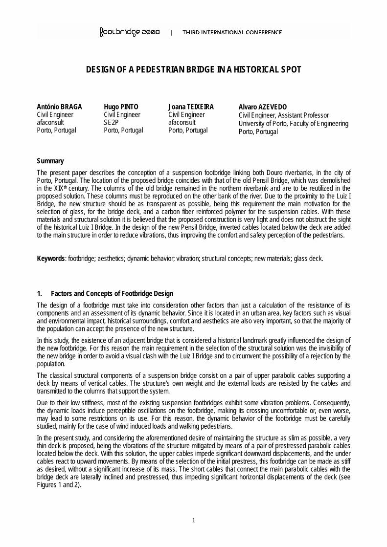
In this study, the existence of an adjacent bridge that is considered a historical landmark greatly influenced the design of the new footbridge. For this reason the main requirement in the selection of the structural solution was the invisibility of the new bridge in order to avoid a visual clash with the Luiz I Bridge and to circumvent the possibility of a rejection by the population.
The classical structural components of a suspension bridge consist on a pair of upper parabolic cables supporting a deck by means of vertical cables. The structure's own weight and the external loads are resisted by the cables and transmitted to the columns that support the system.
Due to their low stiffness, most of the existing suspension footbridges exhibit some vibration problems. Consequently, the dynamic loads induce perceptible oscillations on the footbridge, making its crossing uncomfortable or, even worse, may lead to some restrictions on its use. For this reason, the dynamic behavior of the footbridge must be carefully studied, mainly for the case of wind induced loads and walking pedestrians.
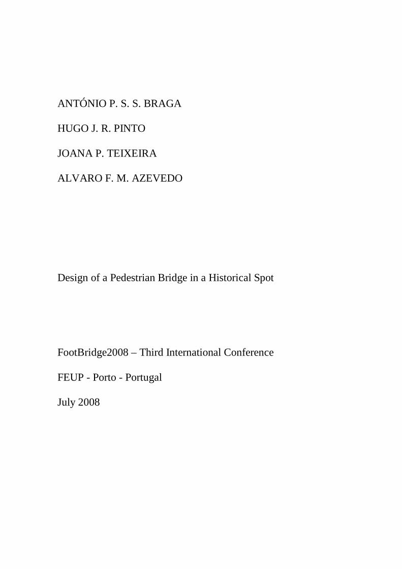
In the present study, and considering the aforementioned desire of maintaining the structure as slim as possible, a very thin deck is proposed, being the vibrations of the structure mitigated by means of a pair of prestressed parabolic cables located below the deck. With this solution, the upper cables impede significant downward displacements, and the under cables react to upward movements. By means of the selection of the initial prestress, this footbridge can be made as stiff as desired, without a significant increase of its mass. The short cables that connect the main parabolic cables with the bridge deck are laterally inclined and prestressed, thus impeding significant horizontal displacements of the deck (see Figures 1 and 2).
2
Fig. 1 - Original sketch of the proposed footbridge
Fig. 2 – Photomontage showing the new Pensil Bridge and its impact on the ancient Luiz I Bridge
2. Structural Design
The solution proposed in this paper is the result of an evolving process that comprised several steps. The present structural solution combines the results of static and dynamic analyses of several types of cable systems, thus attaining the dynamic efficiency and static resistance required for a footbridge. Throughout this process, it could be assessed that prestressed main cables in conjunction with a system of vertical cables is the ideal solution for the case of static loads, and a combination of the prestressed main cables with a set of diagonal cables significantly improves the dynamic behavior of the bridge. By adopting a superposition of both these cable layouts a very good solution could be obtained, accompanied with a reduction of the diameter of the cables, when compared to each of the previously considered solutions. In the adopted design, the diameter of the upper cables is 15.0 cm, the diameter of the under cables is 15.0 cm and the diameter of the shorter cables of the vertical-diagonal system is 3.0 cm. This structure exhibits truss behavior, with displacements and natural frequencies in observance of the code requirements, without compromising an attractive and innovative architectural design.
3
3. Structural Analysis
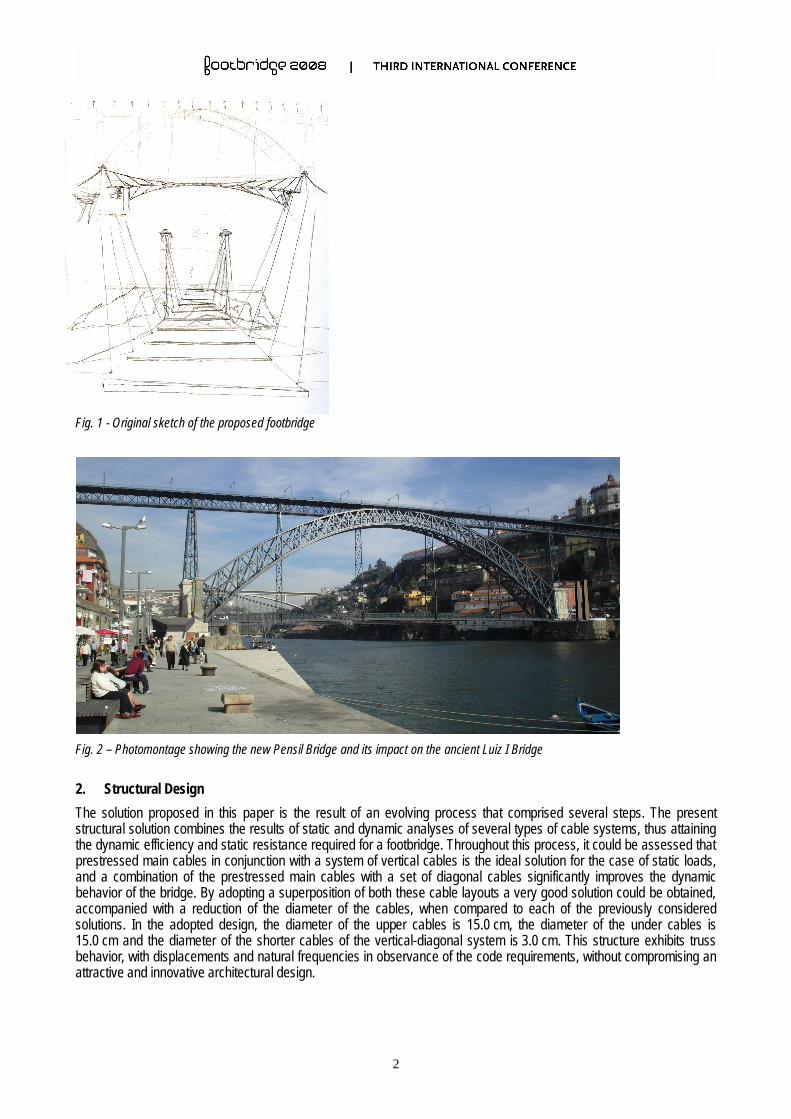
In the evaluation of the global behavior of the structure a nonlinear analysis software package was used (Robot Millennium V.17). The cable/deck structural system was separated from the granite towers, since their deflections at the top can be considered as negligible when compared with those of the superstructure.
The structural analysis is based on a three-dimensional model of the bridge (see Figure 3). This model comprises the upper parabolic cables, the lower parabolic cables, the vertical and diagonal hangers connecting the parabolic cables with the deck, and the deck itself, which is composed of S355 steel equal-leg angles. The support conditions that are considered in the model consist of pinned supports at the main cable extremities and at the north side of the deck, being the south side of the deck connected to the abutment by means of sliding supports to allow length variations of the deck.
Fig. 3 - Structural analysis model of the new Pensil Bridge
3.1 Loads
The loads applied to the model comprise the weight of the structural members, the glass slab self-weight (2.5 kN/m2), the live load imposed by the Portuguese code (4.0 kN/m2), wind load, flood load and temperature load.
The wind load is simplistically considered as the dynamic pressure of the wind for a speed of 25 m/s. The more appropriate evaluation of this load would imply the construction of an aero-elastic model and its wind tunnel testing. Since this study could not be carried out in the context of the present work, a dynamic pressure coefficient of 0.38 kN/m2, according to the Portuguese RSAEEP code, is considered. The force coefficient for the cables is 1.1 and for the angles of the deck is 1.8.
The initial tension of the cable system is included in the numerical model by means of a negative temperature variation of the upper and lower parabolic cables. The amount of pre-tension significantly influences both the static and the dynamic behavior of the bridge. By increasing its initial tension the structure becomes stiffer, thus improving its dynamic behavior. However, this increase implies the presence of higher static forces in the structure. By analyzing the results of both types of analyses, a temperature variation of 500ºC for the upper cables and of 250ºC for the lower cables was adopted. This leads to a tensile force of 2200 kN in the upper cables and of 1140 kN in the lower cables, considering only the permanent loads.
3.2 Global Analysis Results
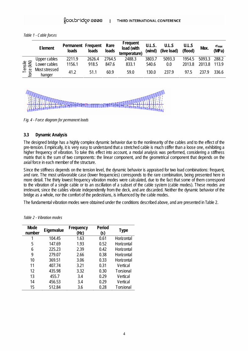
For all the load cases and combinations taken into consideration, the maximum stress in the upper cables is 288 MPa, in the lower cables is 114 MPa, and in the hangers is 337 MPa. Due to a certain lack of code standards related to structures made of carbon fiber reinforced polymers, in this particular application the obtained safety factors are not fully supported by the structural regulations, but are considered to be satisfactory.
For the serviceability limit states the calculated deflections are very small, due to the high stiffness of the structure. The maximum obtained deflection is 7.6 cm for the rare combination of load cases.
The designed bridge has a highly complex dynamic behavior due to the nonlinearity of the cables and to the effect of the pre-tension. Empirically, it is very easy to understand that a stretched cable is much stiffer than a loose one, exhibiting a higher frequency of vibration. To take this effect into account, a modal analysis was performed, considering a stiffness matrix that is the sum of two components: the linear component, and the geometrical component that depends on the axial force in each member of the structure.
Since the stiffness depends on the tension level, the dynamic behavior is appraised for two load combinations: frequent, and rare. The most unfavorable case (lower frequencies) corresponds to the rare combination, being presented here in more detail. The thirty lowest frequency vibration modes were calculated, due to the fact that some of them correspond to the vibration of a single cable or to an oscillation of a subset of the cable system (cable modes). These modes are irrelevant, since the cables vibrate independently from the deck, and are discarded. Neither the dynamic behavior of the bridge as a whole, nor the comfort of the pedestrians, is influenced by the cable modes.
The fundamental vibration modes were obtained under the conditions described above, and are presented in Table 2.
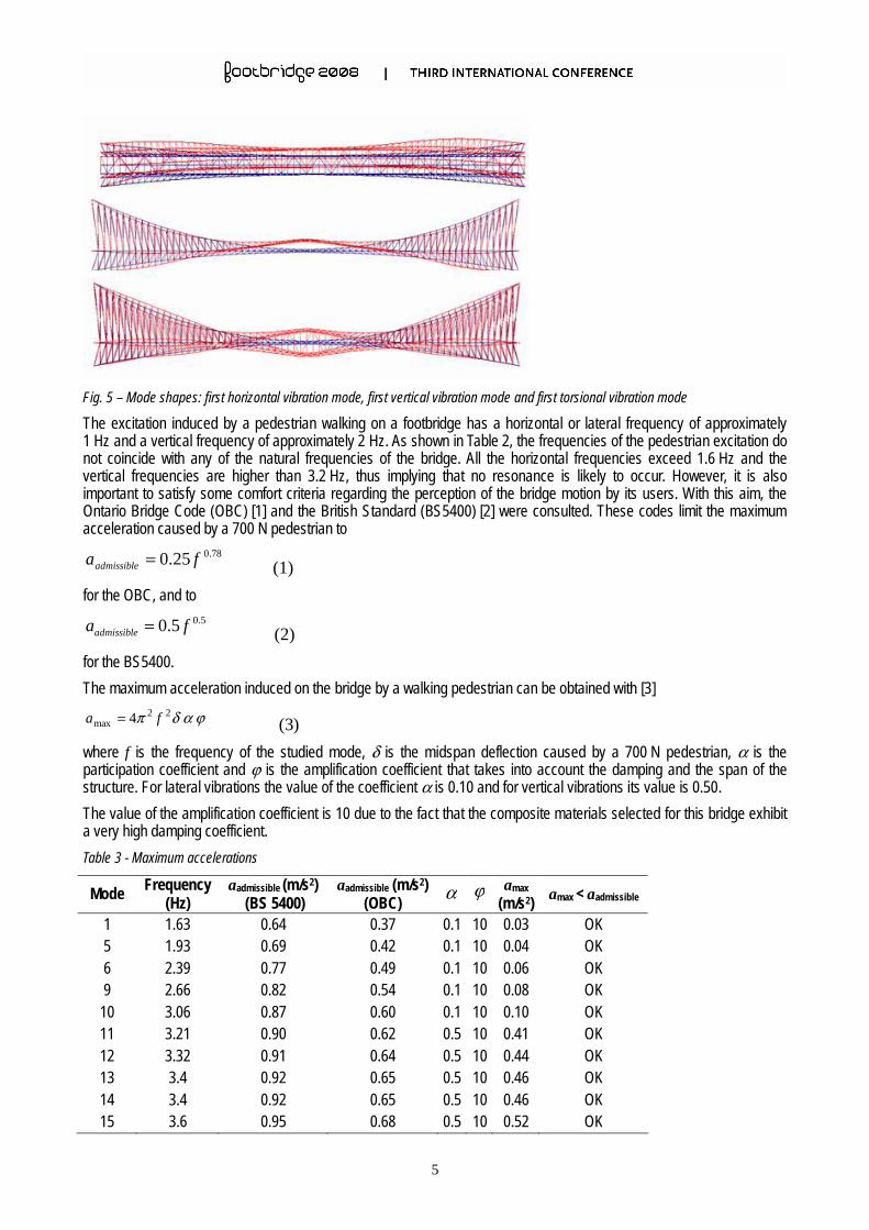
Fig. 5 – Mode shapes: first horizontal vibration mode, first vertical vibration mode and first torsional vibration mode
The excitation induced by a pedestrian walking on a footbridge has a horizontal or lateral frequency of approximately 1 Hz and a vertical frequency of approximately 2 Hz. As shown in Table 2, the frequencies of the pedestrian excitation do not coincide with any of the natural frequencies of the bridge. All the horizontal frequencies exceed 1.6 Hz and the vertical frequencies are higher than 3.2 Hz, thus implying that no resonance is likely to occur. However, it is also important to satisfy some comfort criteria regarding the perception of the bridge motion by its users. With this aim, the Ontario Bridge Code (OBC) [1] and the British Standard (BS5400) [2] were consulted. These codes limit the maximum acceleration caused by a 700 N pedestrian to
78.025.0 faadmissible = (1)
for the OBC, and to 5.05.0 faadmissible = (2)
for the BS5400.
The maximum acceleration induced on the bridge by a walking pedestrian can be obtained with [3]
ϕαδπ 4 22max fa = (3)
where f is the frequency of the studied mode, δ is the midspan deflection caused by a 700 N pedestrian, α is the participation coefficient and ϕ is the amplification coefficient that takes into account the damping and the span of the structure. For lateral vibrations the value of the coefficient α is 0.10 and for vertical vibrations its value is 0.50.
The value of the amplification coefficient is 10 due to the fact that the composite materials selected for this bridge exhibit a very high damping coefficient.
Table 3 - Maximum accelerations
Mode Frequency (Hz)
aadmissible (m/s2) (BS 5400)
aadmissible (m/s2) (OBC)
α ϕ amax
(m/s2) amax < aadmissible
1 1.63 0.64 0.37 0.1 10 0.03 OK 5 1.93 0.69 0.42 0.1 10 0.04 OK 6 2.39 0.77 0.49 0.1 10 0.06 OK 9 2.66 0.82 0.54 0.1 10 0.08 OK
10 3.06 0.87 0.60 0.1 10 0.10 OK 11 3.21 0.90 0.62 0.5 10 0.41 OK 12 3.32 0.91 0.64 0.5 10 0.44 OK 13 3.4 0.92 0.65 0.5 10 0.46 OK 14 3.4 0.92 0.65 0.5 10 0.46 OK 15 3.6 0.95 0.68 0.5 10 0.52 OK
6
As shown in Table 3, the proposed bridge satisfies the limits imposed by both codes, thus implying that its oscillations are very unlikely to become uncomfortable to the pedestrians.
It is also important to emphasize that it is possible to tune the cable system in the future, i.e., additional prestress can be applied to the bridge in the occurrence of significant losses that might reduce the quality of the bridge in terms of vibration perception by the pedestrians. An eventual increase of the installed forces is admissible, since the structural system is not stressed to its limit in terms of static loads, being the diameter of the cables imposed by the dynamic behavior requirements.
3.4 Design of the Glass Deck
Transparency was the main criterion for the selection of the material to be used in the floor of the bridge deck. For this reason the obvious choice was a fully transparent laminated glass, whose characteristics were obtained in [4]. According to the Portuguese structural code, RSAEEP, the live load in floors to be exclusively used by pedestrians consists on a uniform load, whose characteristic value is 4 kN/m2. This live load and the dead load of each rectangular panel are used in the design formula (4) to calculate the thickness of each of the four glass sheets.
σβ
n
lpec
2
= (4)
This design formula [4] depends on
n = number of glass sheets
ec = thickness of each glass sheet [mm]
en = nominal thickness of each glass sheet [mm]
eu = nominal thickness of the anti-slip component [mm]
g = 24.5 (n en + eu) = self weight of the floor [Pa]
q = live load [Pa]
p = q + g = total uniformly distributed load [Pa]
l = short span of the rectangular panel [m]
σ = allowable stress [MPa]
β = coefficient of Timoshenko depending on the ratio between length and width
In the calculation of the deflection of each glass floor panel, the participation of the intermediate components in the force distribution is omitted. For aesthetical and psychological reasons, the deflection at the center of the panel should not exceed 1/200 of its short side and must be smaller than 10 mm. These requirements must be satisfied for the combined action of dead and live loads. The maximum deflection at the center of the panel can be calculated with the following formula
3
4
nen
lpf
α= (5)
α = coefficient of Timoshenko depending on the ratio between length and width
The results of the design of the glass panels are included in Table 5.
7
Table 5 - Glass design results p (Pa) σadm
(MPa) l
(m) n β en (mm) q g
ec Deflection
(mm) Verification Thickness (mm)
10 2.0 4 0.3809 19 5000 1862 18.67 4.059 OK 20 2.0 4 0.3809 19 5000 1862 13.19 4.059 OK 40 2.0 4 0.3809 10 5000 980 8.713 3.537 OK
76 76 40
The glass floor has a total thickness of 10 cm, including mastique, silicone, anti-slip and PVB layers. The installation sequence of each laminated glass panel is the following:
- apply a silicone layer at the supports;
- apply a layer of PVB between each pair of glass sheets;
- and, finally, apply an anti-slip coating at the top surface.
3.5 Glass Panel Support Design
The stiffness of the supports of the glass panels must be such that the ratio between its deflection and its length is smaller than 1/500. The width of the support must equal or be greater than 1.5 times the thickness of the floor. However, when the floor thickness is larger than 30 mm, the width should at least be equal to the floor thickness.
3.6 Railings
The spacing of the vertical bars of the bridge railings is 2.5 m (see Figure 6). These railings are calculated for a normal horizontal load of 3500 N and for a longitudinal load of 1750 N. The top horizontal beams are calculated for a normal horizontal load of 1400 N/m.
Fig. 6 - Railings and deck grillage
4. Construction Method
The historical location of the proposed suspension bridge demands strong aesthetic and environmental concerns. Due to the visibility and impact of the new construction, a profound scientific study is mandatory. According to the above described proposal the following construction phases are suggested.
1. Rehabilitation of the existing towers
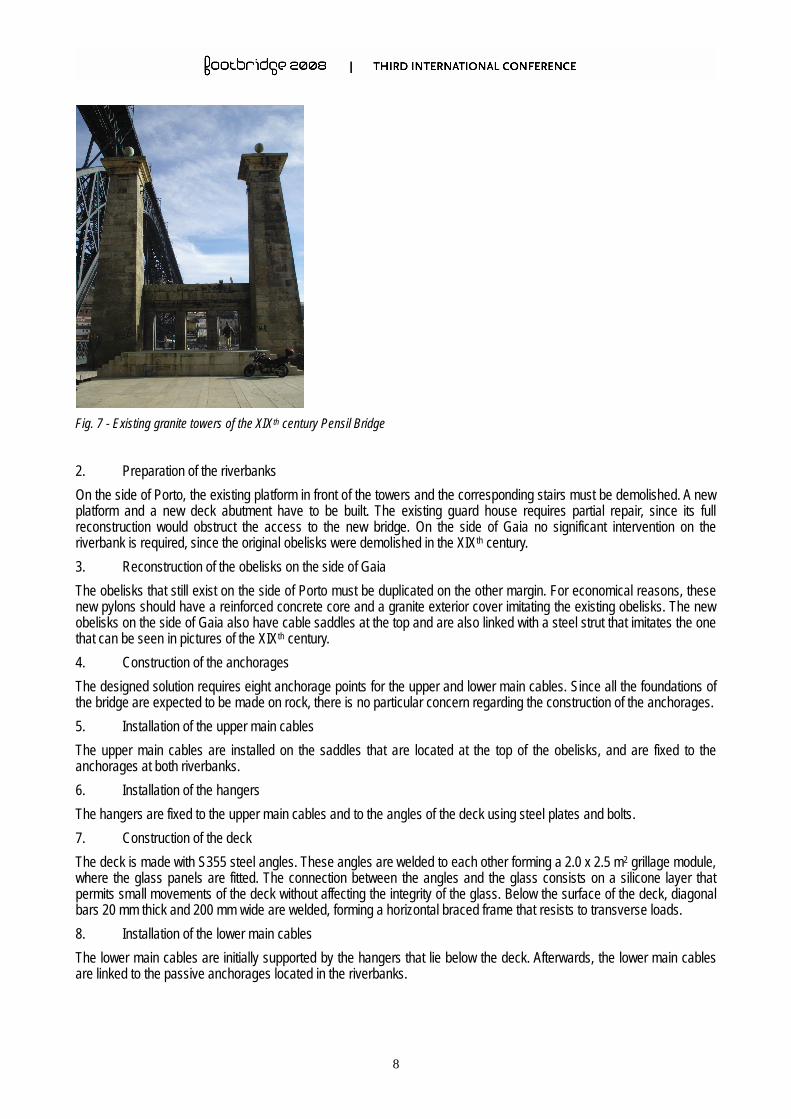
The existing towers, classified as UNESCO World Heritage, are to be rehabilitated and used as structural components of the new bridge (see Figure 7). The main tasks consist of stone cleaning, installation of cable saddles at the top and reconstruction of the top strut, which was present in the XIXth century version of the bridge. Since no detailed evaluation of the condition of the existing obelisks was performed, some preliminary calculations suggest that they can withstand the forces applied by the main cables of the new bridge.
8
Fig. 7 - Existing granite towers of the XIXth century Pensil Bridge
2. Preparation of the riverbanks
On the side of Porto, the existing platform in front of the towers and the corresponding stairs must be demolished. A new platform and a new deck abutment have to be built. The existing guard house requires partial repair, since its full reconstruction would obstruct the access to the new bridge. On the side of Gaia no significant intervention on the riverbank is required, since the original obelisks were demolished in the XIXth century.
3. Reconstruction of the obelisks on the side of Gaia
The obelisks that still exist on the side of Porto must be duplicated on the other margin. For economical reasons, these new pylons should have a reinforced concrete core and a granite exterior cover imitating the existing obelisks. The new obelisks on the side of Gaia also have cable saddles at the top and are also linked with a steel strut that imitates the one that can be seen in pictures of the XIXth century.
4. Construction of the anchorages
The designed solution requires eight anchorage points for the upper and lower main cables. Since all the foundations of the bridge are expected to be made on rock, there is no particular concern regarding the construction of the anchorages.
5. Installation of the upper main cables
The upper main cables are installed on the saddles that are located at the top of the obelisks, and are fixed to the anchorages at both riverbanks.
6. Installation of the hangers
The hangers are fixed to the upper main cables and to the angles of the deck using steel plates and bolts.
7. Construction of the deck
The deck is made with S355 steel angles. These angles are welded to each other forming a 2.0 x 2.5 m2 grillage module, where the glass panels are fitted. The connection between the angles and the glass consists on a silicone layer that permits small movements of the deck without affecting the integrity of the glass. Below the surface of the deck, diagonal bars 20 mm thick and 200 mm wide are welded, forming a horizontal braced frame that resists to transverse loads.
8. Installation of the lower main cables
The lower main cables are initially supported by the hangers that lie below the deck. Afterwards, the lower main cables are linked to the passive anchorages located in the riverbanks.
9
9. Application of the prestress
In order to improve the dynamic behavior of the bridge, and to avoid flutter caused by the wind load, a global stressing of the bridge is required. This prestress can be applied by lifting the saddles that are located at the top of the obelisks, and by simultaneously adjusting the displacement at the anchorages of the upper main cables.
5. Closing Notes
The construction of the proposed footbridge would solve most restrictions regarding pedestrian traffic between both margins of the Douro River, close to the historical centers of Porto and Gaia. Presently, pedestrians share the lower deck of the Luiz I Bridge with motorized traffic, which is a dangerous, unpleasant and ineffective experience.
Due to its location and to the characteristics of its transparent deck, the new Pensil Bridge would certainly become another landmark in the Douro landscape, and would contribute to an increased tourist attraction to the region.
The eventual controversy regarding the obfuscation of the old Luiz I Bridge is overcome by means of a very transparent solution and an adequate integration of the new idea into the existing landscape. The new Pensil Bridge can even be regarded as the reconstruction of a monument that shouldn't have been demolished in the XIXth century.
Further information related to the new Pensil Bridge can be found in [5].
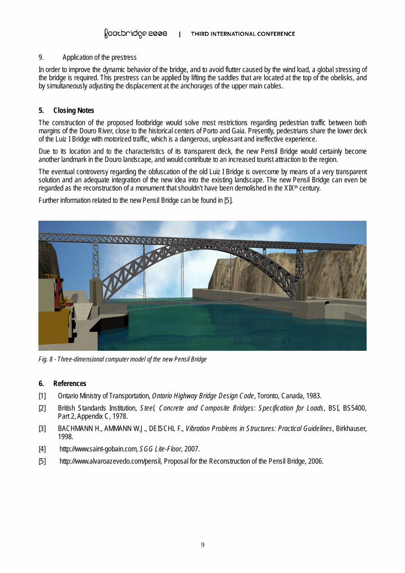
Fig. 8 - Three-dimensional computer model of the new Pensil Bridge