401

Frankfort Public Service District Water Improvement Project FWAT-16-06 Wiley Ford, West Virginia Water Storage Tank – Contract 6
Rummel, Klepper & Kahl, LLP Consulting Engineers
ALL DOCUMENTS INCLUDING DRAWINGS AND SPECIFICATIONS FURNISHED BY THE ENGINEER PURSUANT TO THIS AGREEMENT ARE INSTRUMENTS OF HIS SERVICES IN RESPECT OF THE PROJECT. THEY ARE NOT INTENDED OR REPRESENTED TO BE SUITABLE FOR REUSE BY THE OWNER OR OTHERS ON EXTENSIONS OF THE PROJECT OR ON ANY OTHER PROJECT. ANY REUSE WITHOUT SPECIFIC WRITTEN VERIFICATION OR ADAPTATION BY THE ENGINEER WILL BE AT OWNER’S SOLE RISK AND WITHOUT LIABILITY OR LEGAL EXPOSURE TO ENGINEER, AND OWNER SHALL INDEMNIFY AND HOLD HARMLESS ENGINEER FROM ALL CLAIMS, DAMAGES, LOSSES AND EXPENSES INCLUDING ATTORNEYS’ FEES ARISING OUT OF OR RESULTING THEREFROM. ANY SUCH VERIFICATION OR ADAPTATION PERFORMED BY THE ENGINEER AT THE OWNER’S REQUEST WILL ENTITLE ENGINEER TO FURTHER COMPENSATION AT RATES TO BE AGREED UPON BY OWNER AND ENGINEER. NOTE: REFER TO DRAWINGS PRIOR TO CONSTRUCTION. PLANS AND SPECIFICATIONS MUST BE READ TOGETHER TO UNDERSTAND FULLY WHAT MUST BE BUILT.

Frankfort Public Service District Water Improvement Project FWAT-16-06 Wiley Ford, West Virginia Water Storage Tank – Contract 6
Rummel, Klepper & Kahl, LLP Consulting Engineers
THIS PAGE LEFT BLANK

Frankfort Public Service District Water Improvements Project Contract FWAT-16-06 Wiley Ford, West Virginia Water Storage Tank – Contract 6
Rummel, Klepper & Kahl, LLP Consulting Engineers i
TABLE OF CONTENTS
SECTION IV TECHNICAL SPECIFICATIONS
DIVISION 1 – GENERAL REQUIREMENTS 01010 GENERAL REQUIREMENTS 01015 PROPOSAL AND BIDDING REQUIREMENTS 01020 CONTRACT CONDITIONS 01027 APPLICATION FOR PAYMENT 01070 ABBREVIATIONS OF TERMS AND ORGANIZATIONS 01151 MEASUREMENT AND PAYMENT 01170 SPECIAL PROVISIONS 01200 PROJECT MEETINGS 01300 SUBMITTALS 01500 TEMPORARY FACILITIES 01600 MATERIAL AND EQUIPMENT 01700 PROJECT CLOSEOUT DIVISION 2 – SITE WORK 02040 AUDIO-VIDEO COLOR TAPING
02230 CLEARING AND GRUBBING 02240 DEWATERING
02300 EARTHWORK 02310 SITE GRADING 02311 FINISH GRADING AND SEEDING 02315 TRENCHING, BACKFILLING, and COMPACTING 02316 ROADWAY EXCAVATION, BACKFILLING, AND COMPACTING 02370 EROSION CONTROL DURING CONSTRUCTION 02505 UTILITY RELOCATION 02510 WATER MAIN AND APPURTENANCES 02512 SITE PIPING 02535 PIPE AND PIPE FITTINGS 02610 SITE DRAINAGE 02740 PAVING AND SURFACING 02820 CHAIN LINK FENCE DIVISION 3 – CONCRETE 03300 CAST-IN-PLACE CONCRETE 03400 PRECAST CONCRETE STRUCTURES 03600 GROUT DIVISION 4 – MASONRY NOT USED

Frankfort Public Service District Water Improvements Project Contract FWAT-16-06 Wiley Ford, West Virginia Water Storage Tank – Contract 6
Rummel, Klepper & Kahl, LLP Consulting Engineers ii
DIVISION 5 – METALS NOT USED DIVISION 6 – WOOD AND PLASTICS NOT USED DIVISION 7 – THERMAL AND MOISTURE 07100 WATERPROOFING DAMPROOFING DIVISION 8 – DOORS AND WINDOWS NOT USED DIVISION 9 – FINISHES 09900 PAINTING DIVISION 10 – SPECIALTIES NOT USED DIVISION 11 – EQUIPMENT NOT USED DIVISION 12 – FURNISHINGS NOT USED DIVISION 13 – SPECIAL CONSTRUCTION 13110 CATHODIC PROTECTION
13205 STORAGE TANK, GLASS COATED, BOLTED 13208 STORAGE TANK, WELDED STEEL WITH SELF SUPPORTING ROOF DIVISION 14 – CONVEYING SYSTEMS NOT USED DIVISION 15 – MECHANICAL 15060 INTERIOR PROCESS PIPING 15080 VALVES AND PIPE SPECIALTIES 15950 TESTING PIPING SYSTEMS DIVISION 16 – ELECTRICAL NOT USED

Frankfort Public Service District Water Improvements Project Contract FWAT-16-06 Wiley Ford, West Virginia Water Storage Tank – Contract 6
Rummel, Klepper & Kahl, LLP Consulting Engineers iii
APPENDIX APPENDIX A WV BUREAU OF HEALTH WATER PERMIT WV/NPDES GENERAL PERMIT CONSTRUCTION STORM WATER WV DIVISION OF HIGHWAYS ENTRANCE PERMIT

Frankfort Public Service District Water Improvements Project Contract FWAT-16-06 Wiley Ford, West Virginia Water Storage Tank – Contract 6
Rummel, Klepper & Kahl, LLP Consulting Engineers iv
THIS PAGE LEFT BLANK

Frankfort Public Service District Water Improvement Project FWAT-16-06 Wiley Ford, West Virginia Water Storage Tank – Contract 6
Rummel, Klepper & Kahl, LLP Consulting Engineers
01010 - 1
SECTION 01010
GENERAL REQUIREMENTS
PART 1 - GENERAL
1.01 LOCATION
Work shall be performed at the site location indicated on the Plans. The site is situated within the water service area of the Frankfort Public Service District in Mineral County, West Virginia.
1.02 CONTRACT DOCUMENTS
A. The work under this contract shall be performed in accordance with and subject to all terms, conditions and provisions of the following:
1. Project Manual
2. Contract Drawings
3. Standard Specifications and Standard Details
4. Any other Contract Documents so defined in the Standard Specifications.
B. In the event there are conflicting requirements in these documents, the contractor shall follow the more stringent requirements. In interpreting these requirements, the interpretation of the Engineer shall be final.
C. Project Manual
1. The Project Manual contains the Advertisement for Bids, Information for Bidders, Bid, Bid Bond, Performance Bond, Payment Bond, Notice of Award, Notice to Proceed, Agreement, General Conditions, Supplemental General Conditions, Equal Employment Opportunity Contract Compliance Notices, Wage Rates – Federal, General Requirements and Specifications.
D. Contract Drawings
1. Frankfort Public Service District, Water Improvement Project, Contract FWAT-16-06-Water Storage Tank.
Bids are for furnishing all labor, materials, equipment, and performance of work for the Frankfort Public Service District, Water Improvement Project Contract 6, Water Storage Tank and other work necessary to complete the project as more fully shown in the Plans and Specifications prepared by Rummel, Klepper & Kahl, LLP.
2. The Contract Drawings consists of 22” X 34" sheets which indicate plans, profiles, sections, details, and notes for

Frankfort Public Service District Water Improvement Project FWAT-16-06 Wiley Ford, West Virginia Water Storage Tank – Contract 6
Rummel, Klepper & Kahl, LLP Consulting Engineers
01010 - 2
completing the work under this Contract. Due to the small scale of the Plans, it is not possible to indicate all fittings, accessories, or incidentals required to complete the work. However, this does not relieve the Contractor of his obligation to provide such fittings, accessories, or incidentals in order to complete the Contract in every respect.
3. It is not intended that the Plans be scaled to determine dimensions or elevations. The Contractor shall conduct his work in accordance with the survey data, dimensions, and elevations specifically noted on the Drawings.
4. The ENGINEER will furnish the Contractor 3 sets of plans and specifications at no cost. If additional copies are requested, they will be furnished for the cost of reproduction.
1.03 SCOPE
The Contractor shall provide labor, materials, equipment and services, and perform all operations required for completion of Work of this Contract as specified and as indicated on the Contract Drawings.
1.04 REFERENCED STANDARDS AND SPECIFICATIONS
A. SEE SECTION 01070 – ABBREVIATIONS OF TERMS AND ORGANIZATIONS
1.05 PERMITS (AND CERTIFICATES)
A. Such permits, licenses, insurance policies, as may be required to comply with Federal, State and local laws in conducting the work, shall be provided by the Contractor at his own expense, except as herein provided. The Contractor shall include in his bid all costs relating to permits, licenses, insurance premiums, administrative and inspection costs.
B. The Owner has or will obtain a permit for any work within State Roads and the Contractor shall perform all work in accordance with the requirements of this permit.
C. The Owner has or will obtain all of the necessary waterway construction permits for construction of the proposed work. The Contractor shall perform all work in accordance with the requirements of this permit.
D. The Owner has or will obtain a permit for the work from the Department of Environmental Protection. The Contractor shall perform all work in accordance with the requirements of this permit.
E. All permits obtained by the Owner are included in the appendix.
1.06 COMPLIANCE WITH LAWS, ORDINANCES CURRENTLY IN EFFECT
A. The Contractor shall at all times observe and comply with all Federal, State and/or local laws, ordinances, rules and regulations in any manner affecting the conduct of the work, and all such orders or decrees as exist at present and those which may be enacted later, by bodies or tribunals that have any jurisdiction or authority over the work, and shall indemnify and save harmless the Owners and

Frankfort Public Service District Water Improvement Project FWAT-16-06 Wiley Ford, West Virginia Water Storage Tank – Contract 6
Rummel, Klepper & Kahl, LLP Consulting Engineers
01010 - 3
their agents, against any claims or liability arising from or based upon violations of any such law, ordinance, regulation, order or decrees, whether by himself or by his employees.
B. Should the Contractor elect to ignore the conditions stipulated in paragraph 1.05 (A) above and proceed with the work or variance with any applicable ordinances or code, the Contractor shall remove such work without cost to the Owner and proceed with the work in a manner as specified by the Engineer.
C. The Contractor's attention is specifically directed to the fact that the paragraph above shall be taken to include all applicable requirements of the Occupational Safety and Health Act and that it shall be the Contractor's complete and entire responsibility to determine, observe and comply with all such requirements without direction of the Engineer.
D. Contractor shall comply with applicable laws and ordinances governing the disposal of surplus excavation, materials, debris and rubbish on or off the project and commit no trespass on any public or private property in any operation due to or connected with the work.
E. The Contractor shall schedule his earthwork, paving and trenching operations, subject to approval by the Engineer, to insure that the land areas thereby exposed to increased erosion will not be exposed more than the briefest period of time possible. Graded areas shall be seeded and mulched immediately after topsoil is placed to finished elevations. Turf areas shall not be disturbed beyond the limits of excavations and graded areas.
F. Use of Explosives – The use of explosives will not be permitted adjacent to or on any existing structures unless authorized in writing by the Engineer. Such authorization shall not relieve the Contractor of full responsibility for damages which may occur. When the use of explosives is permitted, the Contractor shall exercise utmost care not to endanger life or property, and whenever necessary, the number of charges and sizes of the charge shall be reduced. Only expert powder men, approved in advance by the Engineer, shall handle and use explosives; all explosives shall be securely stored in conformity with the provision of all statutes, laws, ordinances and regulations in force at the time of construction. All storage places shall be clearly marked "DANGER - EXPLOSIVES".
G. Watchmen, Barricades, Danger and Detour Signs
1. The Contractor shall place sufficient red or flashing lights on or near the work and keep them burning from sunset to sunrise; he shall erect suitable railings, barricades, detour signs, danger signals or signs, fences or other protection about open trenches, materials or supplies after delivery, and shall provide watchmen on the work by day or night, all as necessary for the public safety, and for the prevention of accidents during and after the delivery of materials and supplies, and shall at all times take necessary precautions to avoid accident or injury to persons or property. The Contractor shall, upon verbal notice from the Engineer that he has not satisfactorily complied with the foregoing requirements, immediately take such measures to comply therewith as the Engineer may direct, but the Contractor shall not be relieved of his obligations under the Contract by any such notice or directions given by the Engineer, or by his neglect, failure or refusal to give such notice or
Frankfort Public Service District Water Improvement Project FWAT-16-06 Wiley Ford, West Virginia Water Storage Tank – Contract 6
Rummel, Klepper & Kahl, LLP Consulting Engineers
01010 - 4
directions. Highways closed to traffic shall be protected by effective barricades on which shall be placed acceptable warning signs.
2. The Contractor shall request permission from the entity having control of the street or road, for any street or highway to be closed due to his work. Upon receipt of such permission, the Contractor shall send notice to the Engineer of the times and places where barricades and other protective devices will be placed. Contractor shall notify 911 Center in advance of all road closings.
1.07 PROGRESS SCHEDULE
Within 10 days after receipt of the Notice to Proceed, the Contractor shall prepare and submit to the Engineer for approval, a construction progress schedule in the critical path format. The schedule shall show the Contractor's proposed sequence of work and the time and dates required for completion of each activity of the work, with sub-schedules of related activities which are essential to its progress.
The Contractor shall revise the progress schedule monthly during the course of the Contract and resubmit three (3) copies of the revised progress schedule to the Engineer at the regularly scheduled progress meetings. The Engineer will review the revised schedule and return any comments within 10 days. If required by the Engineer, the Contractor shall resubmit a revised schedule within 7 days after receipt of any comments. The detail of information to be included in the construction progress schedule shall include, but not necessarily be limited to, activities related to procurement of materials, submission of working drawings, approvals, fabrication and delivery of materials and equipment to the site, on site or construction operations, including acceptance and testing for work of the Contractor and his subcontractors. The anticipated size of working crews shall also be furnished.
The construction progress schedule shall depict the following:
1. Component activities.
2 Sequential relationship of performance of the activities.
3. Time required to perform each activity.
4. Cost associated with related activities.
The information depicted shall be transformed into a printed schedule which shall indicate for each activity the following information:
1. Activity description.
2. Duration required to perform each activity.
3. Earliest date on which activity may be started.
4. Latest date on which activity can be completed without delaying project completion.
5. Slack or float time that exists for performance of this activity.
Frankfort Public Service District Water Improvement Project FWAT-16-06 Wiley Ford, West Virginia Water Storage Tank – Contract 6
Rummel, Klepper & Kahl, LLP Consulting Engineers
01010 - 5
When and if subsequent analyses indicate the necessity of revision in order to meet Contract time limitations, the Contractor shall supply information and indicate the action to be taken to revise the schedule to accomplish the Contract requirements. The Owner will have the right to withhold payments due the Contractor until such schedule revisions are accomplished.
1.08 DAILY LOG
The Contractor shall submit weekly, to the resident project representative, daily logs outlining the number of people working and their classification, major equipment, and summary of work performed.
1.09 INSTALLATION CERTIFICATES
A. Provide as required by individual Technical Specifications prior to testing equipment or placing equipment into service.
B. When required, obtain and provide the Owner with an Installation Certificate signed by the manufacturer’s field representative attesting that the equipment has been properly installed and is ready for testing and operation.
C. The Contractor shall confer and verify with other contractors as to locations and extent of their work, to the end that interferences and deletions between trades are prevented and embedded or required items are installed in conjunction with the work under this contract. Interconnections between work of other contracts shall be made by the contractor whose work is erected last unless otherwise specifically stated in the Contract Documents, required by the Engineer, or necessitated by the nature or extent of the work.
D. The Contractor hereby guarantees all of the work performed under this contract for a period of twelve (12) months after the approval of the substantial completion, by the Owner as follows:
1. Against all faulty or imperfect materials and against all imperfect and careless and/or unskilled workmanship.
2. That all pipe lines, tanks and structures shall be water tight and that leakage shall not exceed the limits set forth in the Standard Specifications.
3. The Contractor shall, upon receipt of written notice from the Owner, replace with proper workmanship and materials and to re-execute, correct or repair without cost to the Owner, any work which may be found to be improper or imperfect and to restore and maintain all roads, ditches and slope areas.
4. No use or acceptance by the Owner of the work or any part thereof, nor any failure to use the same, nor any repairs, adjustments, replacements or corrections made by the Owner, due to the Contractor's failure to comply with any of his obligations under the Contract Documents shall impair, in any way, the guarantee obligations, assumed by the Contractor under these Contract Documents.
5. That the entire equipment and each and every part thereof, shall operate (with proper care and attention) in a satisfactory and efficient manner, and in accordance with the requirements of the Contract Documents.

Frankfort Public Service District Water Improvement Project FWAT-16-06 Wiley Ford, West Virginia Water Storage Tank – Contract 6
Rummel, Klepper & Kahl, LLP Consulting Engineers
01010 - 6
6. The maintenance period obligations assumed by the Contractor under these Contract Documents shall not be held or taken to be in any way impaired because of the Specifications, indication or approval by or on behalf of the Owner of any articles, materials, means, combinations or things used or to be used in the construction, performance and completion of the work, or any part thereof.
7. In case the Contractor neglects to make such repairs required during the maintenance period, the Engineer may cause such damage to be repaired and made good, at the cost and expense of the Contractor.
8. Maintenance work during the guarantee period shall not include routine maintenance work such as lubrication of equipment, changing of light bulbs, fuses, and routine paint repairs. The Contractor shall turn over to the Owner a maintenance log for all equipment furnished under this Contract prior to receiving conditional acceptance of the Contract work.
9. If other sections of these specifications require a more stringent guarantee, then that requirement shall supersede this section.
1.10 DIRECTION OF WORK
A. The work shall be done under the direction of the Engineer. While it is intended that the Contractor be allowed to carry on the work in accordance with such general plan as may appear to him most desirable, the Engineer, at his discretion, may from time to time direct the order in which, and at points which, the work shall be prosecuted; he may exercise such general control over the conduct of the work, at any time or place as in his judgment shall be required to comply with the intent of the Contract Documents or to safeguard the interest of the Owner and the public, and the Contractor shall have no claim for damages or extra compensation on account of such control, or the necessity to carry on the work in different sequence from that which the Contractor may have contemplated. The Contractor shall immediately comply with any and all orders and instructions given by the Engineer, but nothing herein shall be considered as such assumption of control over the work by the Engineer as to relieve the Contractor of any of his obligations or liabilities under the Contract.
B. The Contractor shall supervise and direct the work efficiently, using his best skill and attention. He shall be solely responsible for the techniques and sequences of construction. The work shall be prosecuted by the Contractor in such a manner, and with sufficient materials, equipment and labor to insure completion on or before the time specified.
C. The Contractor shall keep on the work at all times during its progress, a competent superintendent, authorized to receive orders and act for him, together with the necessary supervisory staff, all satisfactory to the Engineer. The superintendent shall not be changed except with the consent of the Engineer.
D. The Engineer will not be responsible for acts or omissions of the Contractor, any subcontractor, or any of his or their superintendents or employees.

Frankfort Public Service District Water Improvement Project FWAT-16-06 Wiley Ford, West Virginia Water Storage Tank – Contract 6
Rummel, Klepper & Kahl, LLP Consulting Engineers
01010 - 7
1.11 CONTRACTOR’S USE OF PREMISES
A. The Contractor shall confine construction equipment, the storage of materials and equipment, and operations of workmen to within the limits of construction as shown on the Drawings.
B. The Contractor shall assume full responsibility for materials stored on site including materials for which the Owner has made payment. The Contractor shall purchase and maintain such additional amounts of insurance as are necessary to provide coverage against loss or damage to the materials. The Contractor shall take all measures necessary to secure and protect stored materials from vandalism, theft and weather degradation.
C. The Contractor shall transport materials remaining at the completion of the project for which the Owner has made payment to a storage area designated on site by the Owner.
D. The Contractor shall perform his work in a neat manner and, upon completion, shall remove from the site all excess materials, trash and appurtenances not required to be incorporated in the finish work. The Contractor shall be required to effectively protect the portions of the existing facilities to remain; any resultant damage to existing remaining portions of structures, piping systems or equipment thereof shall be restored to conditions existing prior to execution of his work.
1.12 ORDER OF WORK
A. Contractor shall make himself familiar with all alteration and renovation notes on Drawings and actual site conditions. The Contractor shall become familiar with any special conditions or requirements as listed in contract documents or plans or setforth in pre-construction meeting.
B. It shall be the Contractor’s responsibility to arrange with the Engineer a schedule of operation, so as not to inconvenience the operation of the Owner’s program.
C. The Contractor shall be responsible for the protection of the Owner’s building, facilities and improvements within the areas where the work is being performed. Any disturbance or damage to the work being performed by the Contractor, a separate contractor, or to the existing building, improvements or equipment, or any other impairment of the Owner’s facilities resulting from the Contractor’s performance shall be promptly restored, repaired or replaced by the Contractor at no extra cost to the Owner.
D. Contractor shall be responsible for performing his work in such manner so as to maintain essential ingress and egress for visitors and occupants to the Owner’s building and facilities and to continuously maintain all required emergency exits from the circulation between existing facilities. Passageways for emergency exits shall be kept continuously open and free from debris, construction equipment, tools, materials or other hazards. The Contractor shall provide all temporary work which may be required to obtain and maintain all such ingress, egress and circulation requirements; temporary work shall be removed when no longer required.
E. Contractor shall commence the work and so schedule his work, through the Engineer, to avoid interference with the Owner’s operations. Unavoidable interference with the Owner’s operations shall not be carried out without the

Frankfort Public Service District Water Improvement Project FWAT-16-06 Wiley Ford, West Virginia Water Storage Tank – Contract 6
Rummel, Klepper & Kahl, LLP Consulting Engineers
01010 - 8
Owner’s approval obtained not less than forty-eight (48) hours prior to the anticipated interference.
F. Where existing building utilities such as gas, water, electricity or other facilities are required to be curtailed for making connections, extensions of services or other required work, all such work shall be scheduled with and approved by the Owner. All such work shall be scheduled so that it shall not interfere with the Owner’s programs and may be done on weekends, after regular hours or as agreed upon by the Owner. All efforts and construction shall be coordinated so that any curtailment is held to a minimum. In the event any building services are interrupted for a period of time longer than two (2) hours, the Contractor shall, at his expense, provide a suitable temporary bypass to conduct his work and to maintain necessary building services.
G. To insure non-interference with the Owner’s operations during the performance of the work, the Contractor shall remove from the building, facilities and improvements where the work is being performed all trash, combustible materials and debris of all kind being created during the performance of the work and upon completion of the work. This obligation shall also include all debris created by any subcontractors or material men engaged by the Contractor in performing the work. Such debris shall be disposed of to facilities furnished by the Contractor.
1.13 WORK BY OTHERS
A. The Owner may perform additional work related to the project by himself, or he may let other direct contracts therefore which shall contain general conditions similar to these. The Contractor will afford the other contractors who are parties to such direct contacts (or the Owner, if he is performing the additional Work himself) reasonable opportunity for the introduction and storage of materials and equipment and the execution of work, and shall properly connect and coordinate his work with theirs.
B. It is hereby agreed that the Contractor will conduct his work in such a manner and on such a schedule that the respective work of the Contractor and separate contractors shall be carried on simultaneously and in such manner as not to retard the work of one another or the progress of the project. Nothing in the Contract Documents shall be construed to create a contract or third party beneficiary relationship between the Contractor and any separate contractor.
C. If any part of the Contractor’s work depends for proper execution or results upon the work of any such other Contractor (or the Owner), the Contractor will inspect and promptly report to the Engineer in writing any defects or deficiencies in such Work that render it unsuitable for such proper execution and results. His failure so to report shall constitute an acceptance of the other work as fit and proper for the relationship of his work except as to defects and deficiencies which may appear in the other work after the execution of his work.
D. If the performance of additional work by other contractors or the Owner is not noted in the Contract Documents prior to the execution of the contract, written notice thereof shall be given to the Contractor prior to starting any such additional work. If the Contractor believes that the performance of such additional work by the Owner or others causes an additional expense or entitles him to an extension of the Contract Time, the Contractor may submit a claim.

Frankfort Public Service District Water Improvement Project FWAT-16-06 Wiley Ford, West Virginia Water Storage Tank – Contract 6
Rummel, Klepper & Kahl, LLP Consulting Engineers
01010 - 9
1.14 CLEANING UP
A. The Contractor shall continuously keep the work, the site and adjacent properties free from accumulations of waste materials, excess excavation, rubbish and windblown debris resulting from construction operations. Waste materials, excess excavation, debris and rubbish shall be removed from the site periodically and disposed of at legal disposal areas away from the project site. Surplus excavation shall be handled as defined in section 02220, paragraph 3.09.
B. The Contractor shall remove grease, mastics, adhesives, dust, dirt, stains, fingerprints, labels, and other foreign materials from site-exposed interior and exterior surfaces of structures; broom clean exterior paved surfaces; rake clean other surfaces of the grounds; restore areas disturbed by construction; provide continuous dust control during construction; and maintain temporary paving areas during the period prior to permanent paving.
C. At the completion of the work, or each major portion thereof, the Contractor shall remove surplus materials, tools, construction equipment and machinery, and leave the site clean and ready for occupancy by the Owner. Upon completion of construction, the Contractor shall clean and flush existing storm drains in the area of construction.
D. The Contractor shall maintain his area of work. If clean-up is not complied with, 10% of the succeeding progress payments, in addition to the normal contract retainage, will be withheld from the Contractor until such clean-up is performed.
E. The Contractor shall be responsible for providing dumpsters for the collection and disposal of waste and debris, except for hazardous or unsanitary waste materials which shall be handled by Contractor producing such waste. Dumpsters shall be approved by Engineer. Contractor shall comply with NFPA 241 for removal of combustible materials. Hazardous materials shall be containerized for removal from site.
F. Final cleaning shall be as specified in Section 01700 - Project Closeout.
1.15 CUTTING AND PATCHING
A. The Contractor shall be responsible for cutting, fitting or patching required to complete the work or to make its parts fit together properly.
B. The Contractor shall be responsible for cutting and patching required in existing areas during the execution of the Work.
C. The Contractor shall not damage or endanger a portion of the work or fully or partially completed construction of the Owner’s own forces or of separate Contractors by cutting, patching, excavating or otherwise altering such construction. The Contractor shall not cut or otherwise alter such construction by separate Contractors or by the Owner’s own forces except with written consent of the Engineer, Owner and such separate Contractors; such consent shall not be unreasonably withheld. The Contractor shall not unreasonably withhold, from the separate Contractors or the Owner, the Contractor’s consent to cutting or otherwise altering the Work.
D. Final finish of cut and patch areas (i.e., painting, flooring, etc.) shall be performed by the Contractor.
Frankfort Public Service District Water Improvement Project FWAT-16-06 Wiley Ford, West Virginia Water Storage Tank – Contract 6
Rummel, Klepper & Kahl, LLP Consulting Engineers
01010 - 10
1.16 HISTORICAL/ARCHAEOLOGICAL FINDS
If during the course of construction, evidence of deposits of historical or archaeological interest is found, work affecting the find shall be ceased and the Engineer notified. Do not disturb deposits until written notice from Engineer is given to proceed. Compensation for lost time or changes in construction to avoid the find will be made based upon normal change order procedures.
1.17 CONSTRUCTION STAGING AREA
Area location for Contractor’s field office, equipment storage, fabrication, vehicle parking, and Engineer’s field office and parking will be responsibility of Contractor.
1.18 SOIL EROSION AND SEDIMENT CONTROL PLAN
A. This work shall consist of the application of temporary and permanent measures throughout the life of the project in order to control erosion and to minimize the siltation of rivers, streams, lakes and reservoirs. Such measures shall include, but are not limited to, the use of berms, dikes, dams, sediment basins, fiber mats, netting, gravel or crushed stone, mulch, grasses, silt fence, slope drains and other methods whether shown on plans or not.
Erosion and sediment control measures shall comply with all applicable Federal, State and Local laws and regulations concerning environmental pollution control and abatement.
Any conventional sediment and erosion procedures which would normally be expected to be required shall be implemented by Contractor whether shown on plans or not with all associated cost to incidental to other bid prices.
B. The erosion and sediment control features installed by the Contractor shall be acceptably maintained by the Contractor for the duration of the Contract.
C. The Contractor shall source of all borrow material, and the disposal site for excess material. The off-site locations for disposal and borrow shall be approved. Federal, State or Local agencies having jurisdiction. Contractor shall acquire all required permits.
D. The Contractor shall not pollute streams with fuels, oils, bitumens, calcium chloride, acids or harmful materials. It is the responsibility of the Contractor to investigate and comply with all applicable Federal, State and Municipal laws concerning pollution of rivers and streams. All work under this Contract shall be performed in such a manner that objectionable conditions will not be created in rivers, streams, reservoirs, or ponds in or through or adjacent to the project areas.
E. Surface drainage from cuts and fills within the construction limits, whether or not completed, and from borrow and waste disposal areas, shall be held in suitable sedimentation ponds or shall be graded to control erosion within acceptable limits. Temporary erosion and sediment control measures, such as berms, dikes, silt fences, drains or sedimentation basins, if required to meet the above standards, shall be provided and maintained until permanent drainage and erosion control facilities are completed and operative. The area of bare soil exposed at any one time by construction operations shall be held to a minimum. Fills and waste areas shall be constructed by selective placement of materials to

Frankfort Public Service District Water Improvement Project FWAT-16-06 Wiley Ford, West Virginia Water Storage Tank – Contract 6
Rummel, Klepper & Kahl, LLP Consulting Engineers
01010 - 11
eliminate silts or clays on the surface that will erode and contaminate adjacent rivers, streams, lakes or ponds. Further protection of any excavation, storage area, waste area, or fill area shall be provided by the Contractor by the installation and maintenance of a silt fence around the down slope perimeter of such areas.
F. The cost for any excavation and/or fill involved in connection with the construction of erosion, sediment and pollution control devices required for this project shall be included in the other prices bid.
1.19 WATERTIGHTNESS OF STRUCTURES
A. The Contractor shall provide all labor, materials, tools, equipment and devices for testing the water-tightness of new structures, constructed under this Contract. Testing shall be performed prior to the acceptance or placing the structure in operation, but in the case of concrete structures, after the concrete is at least seven days old. All structures, both water holding and dry, are meant to be watertight and free from discernible infiltration and exfiltration.
B. Structures Designed To Contain Liquid
1. Structures designed to contain liquid shall be thoroughly cleaned prior to the introduction of water for test purposes. Before testing a structure all pipelines connecting to the structure shall have been tested and approved for leakage. All structures shall be tested for leakage by filling them to the normal operating level and observing the water level at the end of a five day period. The drop in water level after adjustment for evaporation and rainfall shall not exceed one inch.
2. If any structure fails to meet the above requirements for water tightness, then the Contractor shall drain the structure, locate and repair all leaks and retest the structure as many times as is necessary to obtain a watertight structure as defined herein, all to the satisfaction of the Engineer and at no extra cost to the Owner.
C. Structures designed to be dry shall have the interior thoroughly cleaned below finished grade and pumped dry if necessary. Openings below grade shall be bulkheaded and made tight. After a period of 5 days, interior surfaces will be inspected for accumulation of moisture and any excess accumulation indicative of defects in the structure in the judgment of the Engineer shall be repaired by the Contractor at no cost to the Owner and to the satisfaction of the Engineer.
D. All leaks and defects in structures shall be repaired or remedied without additional compensation at whatever time during the course of the Contract they become apparent.
E. Potable water shall be used for filling structures for leakage tests. There is NOT sufficient potable water supply on site. It shall be the contractor’s responsibility to furnish all water needed for the leak testing of structures.
F. No separate payment will be made for testing structures neither for water tightness nor for the cost of the water used. The cost thereof shall be considered as included in the lump sum and unit prices bid for this Contract.

Frankfort Public Service District Water Improvement Project FWAT-16-06 Wiley Ford, West Virginia Water Storage Tank – Contract 6
Rummel, Klepper & Kahl, LLP Consulting Engineers
01010 - 12
1.20 GENERAL WORKING HOURS
Unless otherwise specified or directed by the Engineer, the regular working day shall begin no earlier than 7:00 A.M.
1.21 INSPECTORS OVERTIME REIMBURSEMENT
Any work necessary to be performed after regular hours, on Saturday(s), Sunday(s) or Legal Holiday(s), shall be performed without additional expense to the Owner. Should the Contractor elect at any time, or from time to time, to conduct his operations on any regular shift of more than forty (40) hours in any week, or on any Saturday(s), Sunday(s) or Legal Holiday(s) and in the opinion of the Engineer, it is necessary for a Resident Project Representative(s), as a consequence thereof, to work more than forty (40) hours in any week, the Contractor shall be responsible for, bear and pay the costs of any overtime earned by the Resident Project Representative(s). The minimum charge for overtime for a Resident Project Representative(s) on Saturday(s), Sunday(s) or Legal Holiday(s) shall be eight (8) hours. Observations of work on Saturday(s), Sunday(s) or Legal Holiday(s), requested by or made necessary by the actions of the Contractor, shall be scheduled and/or approved by the Owner or his representative forty-eight (48) hours in advance. The Contractor shall bear all costs of inspections after the expiration of Contract Time and if an extension of Contract Time is granted by the Owner at the Contractor’s request. However, if the Owner approves an extension of Contract Time related to an increase in the Scope of Work, the Owner shall bear any related cost of Inspection. For purposes of this section, the following Holidays are observed by the Owner: New Years Day – January 1st Good Friday - Day before Easter Memorial Day – Last Monday in May Independence Day – July 4th Labor Day – First Monday in September Thanksgiving Day – Last Thursday in November Christmas Eve - December 24th Christmas Day – December 25th
1.22 PROJECT SIGN
A. This project will require the installation of signs as specified in the Supplementary General Conditions.
B. Each sign shall be adequately supported as site conditions may require. Each sign shall be mounted at a proper distance above grade to permit public viewing, unless otherwise required.
C. Each sign shall be built of ¾-inch exterior type high density-overlay plywood in accordance with agency requirements.
D. The signs shall be installed prior to the start of any construction work. Cost will be included in mobilization.
E. It shall be the responsibility of the Contractor to protect and maintain the signs in good condition throughout the life of the project.
END OF SECTION

Frankfort Public Service District Water Improvement Project FWAT-16-06 Wiley Ford, West Virginia Water Storage Tank – Contract 6
Rummel, Klepper & Kahl, LLP Consulting Engineers
01015 - 1
SECTION 01015
PROPOSAL AND BIDDING REQUIREMENTS
PART 1 - GENERAL
1.01 PROPOSAL REQUIREMENTS AND CONDITIONS
A. The Bidder shall submit his BID upon the blank bid forms which are provided by the engineer. The Bidder shall specify a lump sum price or a unit price, as may be required, in dollars and cents, in the format shown for each pay item given.
B. The bid forms shall be filled out in ink or typewritten. The bid, if submitted by an individual, shall be signed by the individual in full; if submitted by a partnership, shall be signed by such member or members of the partnership as have authority to bind the partnership; if submitted by a corporation, shall be signed in the name of such corporation by some authorized officer, or agent thereof, who shall subscribe his name and office and affix the corporate seal. If not signed by an officer there must be attached a copy of that portion of the by-laws, or a copy of a Board resolution, duly certified by the Secretary, showing the authority of the person so signed on behalf of the corporation. Post office address, county and state, and telephone number must be given after the signature of the person signing the Bid.
C. Bidders must be prepared to present satisfactory evidence and references as to responsibility and experience in the character of the work which they propose to do, and demonstrate that they are fully prepared with the necessary capital, material and machinery to conduct the work for which they propose to contract, to the satisfaction of the Engineer, and to begin promptly within ten (10) days after notice to do so.
1.02 BIDDER QUALIFICATION AND LICENSES
A. The Frankfort Public Service District may make such investigations as deemed necessary to determine the ability of the bidder to perform the work, and the bidder shall furnish the Owner all such information and data for this purpose as the Owner may request. The Owner reserves the right to reject any bid if the evidence submitted by, or investigation of, such bidder fails to satisfy the Owner that such Bidder is properly qualified to carry out the obligations of the Agreement and to complete the work contemplated therein.
B. Bidders must be licensed prior to bid opening as required by the State of West Virginia.
1.03 EXAMINATION OF PLANS, SPECIFICATIONS AND SITE
A. Bidders shall make a personal examination of the location of the proposed work and of the surroundings thereof, and shall thoroughly acquaint themselves with the details of the work to be done and all the conditions and obstacles likely to be encountered in the performance and completion of the work. Bidders shall inform themselves as to the facilities for the transportation, handling and storage of equipment and materials, shall carefully study the plans, specifications and other contract documents to satisfy themselves concerning the conditions under which the work is to be done and the character, qualities and quantities of work to be performed and materials to be furnished; and to be prepared to execute a

Frankfort Public Service District Water Improvement Project FWAT-16-06 Wiley Ford, West Virginia Water Storage Tank – Contract 6
Rummel, Klepper & Kahl, LLP Consulting Engineers
01015 - 2
finished job in every particular.
Bidder is responsible to determine existing site conditions, including but not limited to depth and type of street or road pavements requiring excavation, type of trench material to be encountered during excavation, presence and extent of groundwater and any other conditions affecting cost of unit bid work. Bidder shall request permission from entities controlling streets or roads to perform testing as deemed necessary. Test pits may be performed with permission of land owner. Failure of bidder to adequately investigate existing site conditions shall not constitute reason for a changed condition request.
B. Should the bidder find discrepancies in the plans, specifications or Contract Documents or should he be in doubt as to the meaning or intent of any part thereof, he must, prior to bid submission, request clarification from the Engineer who will issue an addendum or otherwise clarify the matter. Every request for such interpretation should be in writing addressed to RUMMEL, KLEPPER & KAHL, LLP, and marked "Request for Clarification – Frankfort Public Service District, Water System Improvement, Contract FWAT-16-06, Water Storage Tank". The request must be received at least seven (7) working days prior to the date fixed for the opening of bids. Any and all such interpretations, and any supplemental instructions will be mailed by certified mail with return receipt requested to all prospective bidders (at the respective addresses furnished for such purposes), not later than five (5) working days prior to the date fixed for the opening of bids. Failure to request such clarification is a waiver to any claim by the bidder for expense made necessary by reason of later interpretation of the Contract Documents. All addenda issued during the time for bidding shall form a part of the Contract requirements and shall be considered by the bidders in preparing their bids. Failure of any bidder to receive any addendum of interpretation shall not relieve such bidder from any obligation under his bid as submitted. A bidder's exception to the specifications does not obligate the owner to change the specifications. Verbal explanations or interpretations of the contract documents will not be made.
C. The failure of any Contractor to examine any form, instrument or document shall in no way relieve the Contractor from any obligation in respect to his bid.
1.04 BID BOND
Each bid must be accompanied by a Bid Bond of the character and amount indicated in the Information For Bidders section, made payable to the Owner.
1.05 DELIVERY OF BIDS
A Bid shall be submitted no later than the date and time prescribed and at the place indicated in the Advertisement or Invitation to Bid. The two envelope system will be used for bidding this project.
1.06 WITHDRAWAL OF BIDS
Bid may be withdrawn after it has been deposited with the Owner, provided the Bidder makes his request in writing to the Owner and prior to the time of opening of the Bid. Withdrawn Bids will be returned to the Bidder unopened and unread.
Frankfort Public Service District Water Improvement Project FWAT-16-06 Wiley Ford, West Virginia Water Storage Tank – Contract 6
Rummel, Klepper & Kahl, LLP Consulting Engineers
01015 - 3
1.07 PUBLIC OPENING OF BIDS
Bids will be opened publicly and read at the time and date set in the advertisement or other notice to contractors, at the location. Bidders or their authorized agents are invited to be present.
1.08 DISQUALIFICATION OF BIDDERS
A. The following causes will be considered sufficient to disqualify any bidder, either prior or subsequent to opening of bids, and no bids from disqualified bidders will be considered for contract awards:
1. Interest by the same individual, partnership, firm or corporation in more than one bid on a contract except that any individual, partnership, firm or corporation may have an interest in a contract as a bidder and also be named in proposals with other bidders as a subcontractor.
2. Collusion among or between bidders.
3. Unbalanced proposals; i.e., proposals in which the prices bid for some items are, in the judgment of the Engineer, out of all reasonable proportion to those bid for other items.
4. Lack of responsibility on the part of bidders.
5. Incomplete work which, in the judgment of the Engineer, might hinder or prevent the prompt completion of the subject work if awarded.
6. A history of failure to pay or satisfactorily settle all reasonable and just bills due for labor and materials on former contracts.
1.09 PRE-BID CONFERENCE
A pre-bid conference will be conducted by the Engineer at place and time specified in the Information for Bidders. ATTENDANCE IS MANDATORY.
1.10 CONSIDERATION OF BIDS
A. After the bids have been publicly opened and read, the bids will be canvassed by the Engineer and the apparent low Bidder announced. The Owner reserves the right to reject any or all bids, or to advertise for new bids, to proceed to do the work otherwise, or to abandon the work, as the best interests of the Owner may require.
B. In the event of a discrepancy between the unit bid price and the extensions, (product of quantity and unit price) the unit price will govern. In case of a discrepancy between prices written in words and those written in figures, the prices written in figures will govern.

Frankfort Public Service District Water Improvement Project FWAT-16-06 Wiley Ford, West Virginia Water Storage Tank – Contract 6
Rummel, Klepper & Kahl, LLP Consulting Engineers
01015 - 4
1.11 RETURN OF BID BOND
The Owner will hold the bid bond of the successful low bidder until the execution and delivery of the contract documents, whereupon it shall be returned. All other bid bonds will be returned as soon as award is made.
END OF SECTION

Frankfort Public Service District Water Improvement Project FWAT-16-06 Wiley Ford, West Virginia Water Storage Tank – Contract 6
Rummel, Klepper & Kahl, LLP Consulting Engineers
01020 - 1
SECTION 01020
CONTRACT CONDITIONS
PART 1 - GENERAL
1.01 CONTRACT BOND REQUIREMENTS
The successful Bidder shall, at the time of the execution of the contract, furnish individual performance and payment bonds, each in a sum equal to the full amount of the contract, according to the Performance Bond and Payment Bond sections.
1.02 EXECUTION OF CONTRACT
The contract shall be signed by the successful Bidder and returned together with satisfactory performance and payment bonds within fifteen (15) days after he has received notice of award. In case of failure on the part of the Contractor to enter into contract and furnish satisfactory bond as required in the Information for Bidder section, the guarantee accompanying his bid will become forfeited to the Owner, not as a penalty, but in liquidation of damages sustained. Award may then be made to the next lowest responsible bidder, or the work will be re-advertised, or the Owner may proceed in any lawful manner deemed advisable to accomplish the work.
1.03 SERVICE OF NOTICE
The mailing, in a United States post office box, of a written communication, notice or order, addressed to the Contractor at the business address filed with the Owner, or to his office at the site of the work, shall be considered as sufficient service upon the Contractor of such communication, notice or order and the date of said service shall be the date of such mailing.
1.04 INTENT OF CONTRACT DOCUMENTS
The intent is to prescribe the complete work which the Contractor undertakes to do in full compliance with the contract documents. The Contractor shall perform work in accordance with the lines, grades, cross sections and dimensions shown on the plans. The Contractor shall furnish all materials, implements, machinery, equipment, tools, supplies, transportation, and labor necessary for the prosecution and completion of the work in every detail.
1.05 EXISTING UTILITIES SHOWN ON DRAWINGS
Water mains, storm drains, sanitary sewers, gas mains, and other utilities are shown on the drawings in accordance with the best information available, for the information of the Contractor. The Owner expressly disclaims responsibility for accuracy or completeness of information shown. Existing mains and services shall be carefully protected and any damage to them caused by the work shall be immediately repaired by the Contractor at his expense, using materials of the kinds damaged, to the satisfaction of the Engineer and the Owner of the Utility.
When working around existing utilities, damages and breaks to those utilities will occur from time to time and are to be expected. Contractor shall repair such breaks in accordance with and upon approval of entity owning the damaged utility and Engineer, the cost of which shall be considered incidental and included in other item costs. When existing utilities require significant relocation to allow the performance of the work and

Frankfort Public Service District Water Improvement Project FWAT-16-06 Wiley Ford, West Virginia Water Storage Tank – Contract 6
Rummel, Klepper & Kahl, LLP Consulting Engineers
01020 - 2
with Engineers approval of such location, the Contractor shall submit request for compensation by change order.
1.06 OWNER MAY INCREASE OR DECREASE QUANTITIES
The Owner reserves the right to make such alterations in the plans or in the quantities stated in the bid as may be considered necessary. For unit price items, compensation for such alterations shall be made at the unit prices bid. For lump sum contracts, compensation shall be made as hereinafter stipulated in Sub-section 1.07 Extra Work.
1.07 EXTRA WORK
A. The Contractor shall do such extra work as may be ordered by the Engineer, in writing, and no claim for extra work shall be considered or allowed unless the said work has been so ordered. The extra work will be paid for, either on the basis of lump sum or unit prices mutually agreed upon by the Contractor and the Owner, or as follows:
B. Separate itemized statements and itemized bills, covering the extra work done in each month on each order for extra work, shall be delivered to the Engineer. To all such bills shall be attached vouchers showing the cost of materials, supplied by the Contractor, that have been actually incorporated into such extra work. The Contractor shall permit such examination of his books, vouchers and accounts as the Engineer may require in checking bills for extra work. The amount to be paid the Contractor for extra work shall be made up of the following items:
1. Wages of necessary day laborers, mechanics, and foremen actually employed on extra work for such time, as they are so employed, plus percentage to cover the Contractor's overhead and profit as set forth in Article 12 of Standard General Conditions and Supplements thereto.
2. Expenditures for Workmen's Compensation Insurance, Public Liability Insurance, Social Security taxes, Unemployment Compensation, subsistence and travel allowances, health and welfare benefits, pension fund benefits and any other payroll taxes or benefits required by law or collective bargaining agreement.
3. Actual purchase price, as paid by the Contractor for materials actually incorporated into the extra work plus taxes and percentage to cover the Contractor's overhead and profit as set forth in Article 12 of Standard General Conditions and Supplements thereto.
4. For any machinery or special equipment (other than small tools), whose use has been authorized by the Engineer, a rental rate equal to 80% of the current rates recommended by the Associated Equipment Distributors, which rate includes necessary fuel and lubricants, but excludes operator's wages. Rental shall be paid only for the time equipment is in operation on the work, as follows:
a. For time of use 3 days or less, 1/8 daily rate times hours in operation of the work.
Frankfort Public Service District Water Improvement Project FWAT-16-06 Wiley Ford, West Virginia Water Storage Tank – Contract 6
Rummel, Klepper & Kahl, LLP Consulting Engineers
01020 - 3
b. For time of use more than 3 days but less than 3 weeks, 1/40 weekly rate times hours in operation on the work.
c. For time of use 3 weeks or more, 1/176 monthly rate times hours in operation on the work.
5. Any increase in the cost of the bond incurred as a direct result of the extra work.
6. On extra work performed by an approved subcontractor, an allowance of percentage of the subcontractor's invoice amount to cover the Contractor's overhead and profit as setforth in Article 12 of Standard General Conditions and Supplements thereto. The subcontractor's invoice shall be prepared in accordance with all clauses in this section of the specifications. This percentage allowance shall not apply if the subcontractor is a subsidiary of the contractor or the contractor is the parent company of the subcontractor.
C. Payment for extra work shall include no allowance for the time of superintendents, timekeepers, water boys, or of any workmen or foremen not employed upon the extra work for a definite and easily ascertainable period, nor for the use, maintenance, or repair of tools, nor for maintenance, operation, or repair of machinery, nor office accounting, engineering, or administrative expenses, nor any rent, transportation, interest, or depreciation cost, nor any other overhead, collateral, estimated expense or profit other than the allowances specified herein.
D. All extra work shall be done as economically and expeditiously as possible, and under sufficient but not disproportionate supervision. Labor shall be furnished at current rates and materials charged at the lowest market prices. The Owner may, at his option, furnish any materials, machinery, or equipment required for extra work, and the Contractor shall not be entitled to any allowance or percentage on materials, machinery, or equipment so furnished.
E. The decision of the Engineer shall be final and binding upon all questions relating to extra work. If he deems that any extra work bill is unreasonable or improperly made up in any particular, he shall be empowered to require its revision and adjustment in accordance with such terms as he judges to be fair and reasonable.
F. The Engineer will certify to the Owner for payment, proper bills made out as herein provided upon each written order for extra work. Payment, as approved for the work order completed during any month, will be made upon the current estimate for work completed under the contract during that month, and shall be subject to all the provisions of the contract relating to the payment of current estimates. Unless specifically stipulated, partial payments for extra work under construction will not be made. The Contractor shall not be entitled to any claim for interest on any bill for extra work on account of delay in its approval.
G. All extra work shall be considered a part of the contract, subject to all the provisions thereof.
H. If the Contractor neglects or refuses to perform any required extra work, or to make satisfactory progress in its execution, the Contractor shall not interfere with the prosecution of such work by the Owner.
Frankfort Public Service District Water Improvement Project FWAT-16-06 Wiley Ford, West Virginia Water Storage Tank – Contract 6
Rummel, Klepper & Kahl, LLP Consulting Engineers
01020 - 4
I. During the progress of extra work, the Contractor shall carry forward any or all parts of the work under the contract, or shall suspend any part of the work that may be necessary or required and no claim by the Contractor for extra compensation therefore shall be allowed. The Contractor, however, shall be entitled to an extension of time, to the extent that the Engineer shall certify that the work under the contract has been delayed by the performance of such extra work, provided that a claim for such extension shall be submitted within the time specified for such claims.
1.08 OMITTED ITEMS
Should any items contained in the bid be found unnecessary for the proper completion of the work, the Engineer may, upon written order to the Contractor, delete such items from the contract; such action shall in no way invalidate the contract, and no allowance will be made for items so deleted in making final payment to the Contractor, except for such actual work as may have been done, materials actually purchased, and actual equipment costs incurred, prior to notification of deletion of such items.
1.09 UNAUTHORIZED WORK
Work done beyond the lines and grades shown on the plans, or any extra work done without written authority, is unauthorized and at the expense of the Contractor, and will neither be measured nor paid for by the Owner. Work so done may be ordered removed and replaced at the Contractor's expense.
1.10 DEFECTIVE WORK
Neither inspection nor failure to inspect, nor the presence of any employees of the Owner during the execution of the work, nor approval or acceptance of any part of the work or materials and equipment used therein shall relieve the Contractor of any of his obligations under the Contract, or shall prevent the rejection of said work, materials and equipment, in whole or in part, at any time, thereafter, should said work, materials and equipment be found by the Engineer to be defective or not in accordance with the requirements of the Contract Documents.
1.11 FAILURE TO REMOVE AND RENEW DEFECTIVE MATERIALS AND WORK
A. Should the Contractor fail or refuse to remove and renew any defective material used, or work performed previously, or to make any necessary repairs in an acceptable manner and in accordance with the requirements of the Contract Documents, within the time indicated in writing, the Engineer shall have authority to cause the unacceptable or defective materials or work to be removed and renewed or such repairs to be made or defects corrected at the Contractor's expense.
B. Continued failure or refusal by the Contractor to make any or all necessary repairs promptly, fully, and in an acceptable manner, shall be sufficient cause for the Owner to declare the contract forfeited, in which case the Owner, at his option may purchase materials, tools, and equipment, and employ labor or may contract with any other individual, firm or corporation to perform the work. Any and all costs or expense incurred by the Owner in making such removals, renewals, or repairs, which the Contractor has failed or refused to make, shall be charged against the Contractor and the amount thereof deducted from any monies due or which may become due him under the Contract. Work so performed shall not relieve the Contractor of responsibility for the work performed by him.

Frankfort Public Service District Water Improvement Project FWAT-16-06 Wiley Ford, West Virginia Water Storage Tank – Contract 6
Rummel, Klepper & Kahl, LLP Consulting Engineers
01020 - 5
1.12 SUSPENSION OF WORK
The Owner may suspend the whole or any part of the work under the Contract, if in his judgment such action is necessary or advisable.
1.13 INTERPRETATIONS BY ENGINEER
A. The Engineer will make all necessary interpretations as to the meaning and intent of the specifications and plans and shall give all advice and assistance as contemplated therein or thereby, or in every case in which a difficult or unforeseen condition arises during the prosecution of the work. Should there be any misunderstanding arise to the importance of anything contained in the plans and specifications, the interpretation of the Engineer shall be final and binding. Any errors or omissions on the plans or in the specifications may be corrected by the Engineer when such corrections are necessary for the proper fulfillment of their intent.
B. The Engineer shall in all cases determine the amount, quality, and acceptability of the work to be paid for under the Contract, and shall decide all questions relative to said work. His decision and estimate shall be final and conclusive, and in case any question shall arise between the parties to the contract, such decision and estimate shall be a condition precedent to the right of the Contractor to receive payment under that part of the contract which is in dispute.
C. Interpretations will be rendered by the Engineer as promptly as possible but should delay occur for any reason, the Contractor shall have thereby no claim for damages or extra compensation.
1.14 ALTERATIONS OF PLANS OR OF CHARACTER OF WORK
The Engineer reserves the right to change the alignment, grade, form, length, dimensions, or materials of the work under the Contract, whenever any conditions or obstructions are met that render such changes desirable or necessary. All such alterations shall be paid for, or credit to the Owner determined, on the basis of unit prices bid for such work, or, in the absence of applicable unit prices, on the basis of a lump sum mutually agreed upon by the Contractor and the Owner. Where such alterations reflect a reduction in work, the Contractor shall have no claim for damages or for anticipated profits on the work deleted.
1.15 COORDINATION OF DRAWINGS, STANDARD SPECIFICATIONS, AND SUPPLEMENTAL SPECIFICATIONS
These specifications, the accompanying drawings, supplemental specifications and all supplementary documents are essential parts of the Contract documents. They are intended to be mutually supplementary and to describe and provide for a complete work. In case of discrepancy, figure dimensions shall govern over scale dimensions; supplemental specifications shall govern over both specifications, and drawings and conflicting provisions of this contract.
1.16 COOPERATION OF CONTRACTOR REQUIRED
The Contractor will be supplied with three copies of the plans and specifications, and he shall have available on the work, at all times during its prosecution, one copy each of said plans and specifications. The Contractor shall give the work his constant attention to facilitate its progress and shall give full cooperation to the Engineer.
Frankfort Public Service District Water Improvement Project FWAT-16-06 Wiley Ford, West Virginia Water Storage Tank – Contract 6
Rummel, Klepper & Kahl, LLP Consulting Engineers
01020 - 6
1.17 RELATIONS WITH SUBCONTRACTORS
A. The Contractor agrees to bind each of his subcontractors by the terms of the contract documents as applicable to the work sublet, but no such engagement shall create any contractual relation between the Owner and any subcontractor. All proposed subcontractors must receive prior approval by the Engineer.
B. All suppliers and sub-contractors, including these listed as approved sources, must comply with all requirements as setforth in plans and specifications
1.18 MUTUAL RESPONSIBILITY OF CONTRACTORS
If, through negligence on the part of one Contractor, any other Contractor or any subcontractor suffers loss or damage on the work, the negligent Contractor shall settle with such other Contractor or subcontractor by agreement or arbitration, and shall indemnify and save harmless the Owner against any claim which may arise there from.
1.19 CLAIMS FOR DAMAGE
In any case where the Contractor claims extra compensation is due for work or materials not clearly covered in the Contract Documents, or not ordered by the Engineer as extra work as defined herein, or for any other cause, the Contractor shall notify the Engineer, in writing, of his intention to make claim for such extra compensation before work begins on which the claim is based. If such notification is not given, or the Engineer has not been afforded proper facilities by the Contractor for keeping strict account of actual quantities and cost, any subsequent claim related thereto will be denied. Such notice by the Contractor, and the fact that the Engineer has kept account of quantities and cost thereof, shall not in any way be construed as proof of validity of the claim. If the claim is found to be just, it will be allowed and paid as provided herein for Extra Work.
1.20 PUBLIC CONVENIENCE AND SAFETY
A. The Contractor shall conduct all work in a manner to insure minimum obstruction to traffic and to the convenience and services of the general public. The Contractor shall, unless otherwise specified, provide and maintain in passable condition such temporary highways and bridges as may be necessary to accommodate the traffic diverted from the area affected by the construction, and shall provide and maintain in a safe condition temporary approaches to, and crossing of, intersecting highways. Fire hydrants on or adjacent to the work shall be kept accessible to fire apparatus at all times, and no material or obstruction shall be placed within fifteen (15) feet of any such hydrant. Obstruction of footways, gutters, sewer inlets and portions of highways adjoining the work under construction shall be limited to the extent permitted by the Engineer. Existing mailboxes shall be maintained or reset in positions accessible to the public and to mail deliveries during construction, and subsequent to construction, reset in their final location in satisfactory condition. Work closed down for the winter and at all other times shall be left entirely accessible at all points to fire apparatus. Detour routes over existing public roads will be marked and maintained by the Contractor.
B. Occupational safety laws adopted by the state and local government shall govern all construction and operation of facilities under the Contract.
Frankfort Public Service District Water Improvement Project FWAT-16-06 Wiley Ford, West Virginia Water Storage Tank – Contract 6
Rummel, Klepper & Kahl, LLP Consulting Engineers
01020 - 7
1.21 USE OF EXPLOSIVES
The use of explosives will not be permitted adjacent to or on any existing structures unless authorized in writing by the Engineer. Such authorization shall not relieve the Contractor of full responsibility for damages which may occur. When the use of explosives is permitted, the Contractor shall exercise utmost care not to endanger life or property, and whenever necessary, the number of charges and sizes of the charge shall be reduced. Only expert powder men, approved in advance by the Engineer, shall handle and use explosives; all explosives shall be securely stored in conformity with the provision of all statutes, laws, ordinances and regulations in force at the time of construction. All storage places shall be clearly marked "DANGER - EXPLOSIVES".
1.22 WATCHMEN, BARRICADES, DANGER AND DETOUR SIGNS
A. The Contractor shall place sufficient red or flashing lights on or near the work and keep them burning from sunset to sunrise; he shall erect suitable railings, barricades, detour signs, danger signals or signs, fences or other protection about open trenches, materials or supplies after delivery, and shall provide watchmen on the work by day or night, all as necessary for the public safety, and for the prevention of accidents during and after the delivery of materials and supplies, and shall at all times take necessary precautions to avoid accident or injury to persons or property. The Contractor shall, upon verbal notice from the Engineer that he has not satisfactorily complied with the foregoing requirements, immediately take such measures to comply therewith as the Engineer may direct, but the Contractor shall not be relieved of his obligations under the Contract by any such notice or directions given by the Engineer, or by his neglect, failure or refusal to give such notice or directions. Highways closed to traffic shall be protected by effective barricades on which shall be placed acceptable warning signs.
B. The Contractor shall request permission from the entity having control of street or road, for any street or highway to be closed due to his work. Upon receipt of such permission, the Contractor shall send notice to the Engineer of the times and places where barricades and other protective devices will be placed. The 911 Center shall be immediately notified of any planned or emergency road closing.
1.23 INDEMNIFICATION OF OWNERS
The Contractor shall indemnify and save harmless the Owner from all suits, actions, damages, or costs, of every nature and description, to which the Owner may be subjected or put by reason of injury to persons or property as a result of the work, whether caused by negligence or carelessness on the part of the Contractor, his servants or agents, or to other causes; and so much of the monies due or to become due the Contractor under the contract, as may be considered necessary by the Owner, shall be retained until such suit or claims for damages shall have been settled or otherwise disposed, and satisfactory evidence to that effect furnished to the Owner.
1.24 WAIVER OF CONTRACT
Neither the acceptance of the whole or any part of the work by the Engineer or the Owner, nor any order, measurement or certificate by the Engineer, nor any order by the Owner for the payment of money, nor any payment by the Owner for the whole or any part of the work, nor any extension of time, nor any possession taken by the Owner shall operate as a waiver of any portion of the Contract or any power therein reserved to the
Frankfort Public Service District Water Improvement Project FWAT-16-06 Wiley Ford, West Virginia Water Storage Tank – Contract 6
Rummel, Klepper & Kahl, LLP Consulting Engineers
01020 - 8
Owner, or any right to damages therein provided, nor shall any waiver of any breach of the Contract be held to be a waiver of any other or subsequent breach.
1.25 RESPONSIBILITY FOR PAYMENT OF TAXES
The Contractor is responsible for and shall pay all retail sales, income, real estate, sales and use, transportation and special taxes applicable to and assessable against any materials, equipment, processes and operations incident to or involved in the project unless the Owner is exempt from such taxes. Reference is given to SC 6.10 of the Supplementary General Conditions identifying the Owner’s tax exempt status.
1.26 EMERGENCY WORK
In case of any emergency which threatens loss or injury of property, and/or safety of life, the Contractor will be allowed to act, without previous instructions from the Engineer. He shall notify the Engineer immediately thereafter. Any compensation claimed by the Contractor due to such extra work shall be submitted to the Engineer for consideration.
1.27 TIME OF BEGINNING AND COMPLETION
A. The specified contract time shall begin the day stipulated in the "Notice to Proceed". No work shall be started before receipt of the "Notice to Proceed". Upon commencement of operations the Contractor shall diligently prosecute the work so that is shall be fully completed within the number of days or the completion date stated in the Agreement. Failure to commence work within fifteen (15) days of such notification may be construed by the Owner as just cause for annulment of the Contract.
B. The Owner reserves the right to award adjacent and related work not included in the Contract to another contractor for performance during the progress of the Contract, or to perform such work by Owner forces, and the Contractor for this contract shall cooperate and so conduct his operations as to minimize interference with such adjacent and related work.
1.28 PROSECUTION OF WORK
A. The Contractor shall begin work promptly within the time specified by the Engineer and shall notify the Engineer at least 48 hours before starting work.
B. After the work has been started, it shall be prosecuted continuously on all acceptable working days without stoppage until the entire contract is completed, and the rate of progress shall be at least such as to provide a reasonable basis for expecting the work to be completed within the allotted time.
C. Should the prosecution of work for any reason be discontinued by the Contractor with the consent of the Engineer, he shall notify the Engineer at least twenty-four hours before again resuming operations.
1.29 LIMITATIONS OF OPERATIONS
A. The Contractor shall begin work at such points as may be specified in the Contract, and shall thereafter prosecute the work at such points and in such order as may be prescribed therein.

Frankfort Public Service District Water Improvement Project FWAT-16-06 Wiley Ford, West Virginia Water Storage Tank – Contract 6
Rummel, Klepper & Kahl, LLP Consulting Engineers
01020 - 9
B. No night, Sunday or Holiday work requiring the presence of an Engineer or Inspector will be permitted, except in case of an emergency and/or with written permission of the Engineer. To encourage better utilization of time during the normal 5 day work week, the Contractor shall pay the cost of all engineering and inspection required for Saturday, Sunday, Holiday or night work. The cost of this engineering or inspection will be deducted by the Owner from the Contractor's monthly estimates for work performed and completed as they come due.
C. The Contractor shall notify the Engineer in writing at least two (2) days in advance of such Holiday, Sunday or night that he desires to work, stating the place where said work will be conducted.
1.30 CONTRACT TIME EXTENSION
A. The Contractor shall complete the work in a manner acceptable to the Owner within the time stated in the Contract.
B. The Number of days allowed for the completion of the work included in the contract has been fixed by the Owner, and is stated in the Agreement and Notice to Proceed.
C. In the event of unusual or changed conditions which affect or delay the prosecution and completion of the work, the Engineer will, upon written request from the Contractor, authorize such extension of time as in his judgment, is fair and reasonable.
1.31 DEFAULT OR FAILURE TO COMPLETE WORK ON TIME
Should the Contractor fail to complete the work in full accordance with the contract documents, the Engineer shall determine the number of days that the Contractor is in default in completing the work under the contract, and shall certify the same to the Owner in writing. For each day so certified, the Contractor shall pay to the Owner the sum stipulated in the contract documents for each and every day thereafter, until and including the day when the said work is complete in full accordance with the contract documents, which sum is agreed upon, not as a penalty, but as liquidated damages which the Owner suffers by reason of such default; however, the Owner may, as hereinbefore provided, extend the time for the completion of the work beyond the contract time. The Owner shall be fully authorized and empowered to deduct and retain the amount of such damages. The permitting of the Contractor to finish the work after the time fixed for its completion or after the date to which the time for completion may have been extended, shall not in any way operate as a waiver on the part of the Owner of any rights under the Contract.
1.32 CONTRACTOR'S RIGHT TO STOP WORK OR TERMINATE CONTRACT
If the work should be stopped by court order for a considerable period through no act or fault of the Contractor or if the Owner fails to pay the Contractor within a reasonable time, any sum certified by the Engineer, or commits a substantial violation of the Contract, the Contractor, upon seven (7) days written notice to the Owner and the Engineer, may stop work or terminate the Contract, and recover from the Owner payment for all work executed, any loss sustained upon any equipment or material, and any other reasonable damages.

Frankfort Public Service District Water Improvement Project FWAT-16-06 Wiley Ford, West Virginia Water Storage Tank – Contract 6
Rummel, Klepper & Kahl, LLP Consulting Engineers
01020 - 10
1.33 ABANDONMENT OF OR DELAY IN WORK
If the work under the Contract is abandoned by the Contractor, or if at any time the Engineer is of the opinion, and so certifies in writing to the Owner, that the performance of the Contract is unnecessarily or unreasonably delayed, or that the Contractor is violating any of the provisions of the Contract, or is executing the same in bad faith, or if the work be not fully completed within the time named for its completion, together with such extensions of time as may have been granted, the Owner, by written notice, may order the Contractor to discontinue all work there under, or any part thereof, and thereupon the Contractor shall discontinue the work, or such part thereof, and the Owner may complete said work and deduct the entire cost thereof from any monies due or to become due the Contractor under the Contract. For such completion of the work, the Owner or his contractor may take possession of and use or cause to be used any or all materials, machinery and appliances found on the line of the work. When any part of the Contract is being carried on by the Owner as herein provided, the Contractor shall continue the remainder of the work in conformity with the terms of the contract documents and shall not interfere with the workmen employed by the Owner.
1.34 SUB-LETTING AND ASSIGNMENT
The Contractor shall give his personal attention to the Contract and shall keep the same under his own control, and shall not sublet, sell, transfer, assign or otherwise dispose of, the Contract, or any portion thereof, or of the work provided for therein, or of his right, title, or interest therein, to any person, firm or corporation, without written consent of the Owner. The Contractor shall not, either legally or equitably, assign any monies payable under the Contract, or his claim thereto, except with the consent of the Owner. Written consent by the Owner to subcontract, sublet or assign any portion of the Contract shall not be construed as relieving the Contractor or Surety of any responsibility for the fulfillment of the entire Contract. The Contractor shall not award work to subcontractors in excess of 50 percent of the contract price.
1.35 WORKMANSHIP
A. Only first-class work shall be performed and all materials furnished in carrying out the contract shall be of the character and quality required by the Specifications. Where no standard is specified for such work or materials, they shall be the best of their respective kinds. Any unsatisfactory work done or materials furnished, at whatever time they may be discovered, shall be immediately removed and satisfactorily replaced by the Contractor, when so directed by the Engineer. If the Contractor neglects or refuses to remove such unsatisfactory work or materials within forty-eight hours after the receipt of such notice, or if he makes unsatisfactory progress in doing so, the Engineer may cause said work or material to be removed and satisfactorily replaced, by contract, or otherwise, and the expense thereof will be charged to the Contractor. Such expense shall be deducted from any monies due or to become due the Contractor under the Contract. Upon the completion of the Contract, the entire work shall be delivered to the Owner perfect and complete, in satisfactory working condition.
B. Work and materials which are necessary in the construction, but which are not specifically referred to in the specifications or shown on the drawings, but implied by the Contract, shall be furnished by the Contractor at his own cost and expense and shall correspond with the general character of the work as determined by the Engineer, whose decision as to the necessity for, and character of, such work and materials shall be final and conclusive.

Frankfort Public Service District Water Improvement Project FWAT-16-06 Wiley Ford, West Virginia Water Storage Tank – Contract 6
Rummel, Klepper & Kahl, LLP Consulting Engineers
01020 - 11
1.36 ONLY COMPETENT LABOR SHALL BE USED
A. Only competent labor shall be used. Any employee of the Contractor who uses profane or abusive language to the Inspector or other employees of the Owner, or is otherwise disorderly and interferes with him in the performance of his duties, or who is careless and incompetent, or who shall disobey or evade his instructions, shall be discharged on the request of the Engineer and shall not again be employed except with the Engineer's consent.
B. Gambling or drinking of alcoholic beverages or use of hallucinogenic drugs on or about the site of the work is prohibited and violators shall be summarily discharged at the order of the Engineer.
END OF SECTION

Frankfort Public Service District Water Improvement Project FWAT-16-06 Wiley Ford, West Virginia Water Storage Tank – Contract 6
Rummel, Klepper & Kahl, LLP Consulting Engineers
01020 - 12
THIS PAGE LEFT BLANK

Frankfort Public Service District Water Improvement Project FWAT-16-06 Wiley Ford, West Virginia Water Storage Tank – Contract 6
Rummel, Klepper & Kahl, LLP Consulting Engineers
01027 - 1
SECTION 01027
APPLICATION FOR PAYMENT
PART 1 - GENERAL
1.01 SUMMARY
A. This Section specifies administrative and procedural requirements governing the Contractor’s Applications for Payment.
1. Coordinate the Schedule of Values and Application for Payment with the Construction Schedule, List of Subcontracts, and Submittal Schedule.
1.02 SCHEDULE OF VALUES
A. Coordinate preparation of the Schedule of Values with preparation of the Construction Schedule.
1. Correlate line items in the Schedule of Values with other required administrative schedules and forms, including.
a. Construction Schedule
b. Application for Payment form
c. List of subcontractors
d. List of products
e. List of principal suppliers and fabricators
f. Schedule of submittals.
B. Submit the Schedule of Values to the Engineer at the earliest feasible date, but in no case later than ten (10) days before the date scheduled for submittal of the Contractor’s initial Application for Payment. The Engineer and Owner shall review and approve the proposed Schedule of Values.
C. Format and Content: Use the Project Manual Table of Contents as a guide to establish the format for the Schedule of Values.
1. Identification: Include the following Project identification on the Schedule of Values:
a. Project Name:
b. Engineer Name:
c. Project Number:
d. Owner’s Name:
Frankfort Public Service District Water Improvement Project FWAT-16-06 Wiley Ford, West Virginia Water Storage Tank – Contract 6
Rummel, Klepper & Kahl, LLP Consulting Engineers
01027 - 2
e. Contract Number ; Contract Name: ______________
f. Contractor’s Name and Address:
g. Date of Submittal:
D. Arrange the Schedule of Values in a tabular form with separate columns to indicate the following for each item listed:
1. Generic name
2. Related Specification Section
3. Name of subcontractor
4. Name of manufacturer or fabricator
5. Name of supplier
6. Change Orders (numbers) that have affected value
7. Dollar value
8. Percentage of Contract Sum to the nearest one-hundredth percent, adjusted to total 100 percent.
E. Provide a breakdown of the Contract Sum in sufficient detail to facilitate continued evaluation of Applications for Payment and progress reports. Break principal subcontract amounts down into several line items.
F. Round amounts off to the nearest whole dollar; the total shall equal the Contract Sum.
G. For each part of the work where an Application for Payment may include materials or equipment, purchased or fabricated and stored, but not yet installed, provide separate line items on the Schedule of Values for initial cost of the materials, for each subsequent state of completion, and for total installed value of that part of the work.
H. Schedule Updating: Update and resubmit the Schedule of Values when Change Orders or Construction Change Directives result in a change in the Contract Sum.
1.03 APPLICATIONS FOR PAYMENT
A. Each Application for Payment shall be consistent with previous applications and payments as certified by the Engineer and paid by the Owner.
1. The initial Application for Payment, the Application for Payment at time of Substantial Completion, and the final Application of Payment involve additional requirements.
B. Payment Application Times: Each progress payment date is as indicated in the Agreement or as specified at pre-construction meeting. The period of

Frankfort Public Service District Water Improvement Project FWAT-16-06 Wiley Ford, West Virginia Water Storage Tank – Contract 6
Rummel, Klepper & Kahl, LLP Consulting Engineers
01027 - 3
construction work covered by each Application for Payment is the period indicated in the Agreement or as specified at pre-construction meeting.
C. Application Preparation: Complete every entry on the form, including notarization and execution by person authorized to sign legal documents on behalf of the Owner. Incomplete applications will be returned without action.
1. Entries shall match data on the Schedule of Values and Contractor’s Construction Schedule. Use updated schedules if revisions have been made.
2. Include amounts of Change Orders and Construction Change Directives issued prior to the last day of the construction period covered by the application.
D. Transmittal: Submit six (6) executed copies of each Application for Payment to the Engineer by means ensuring receipt within 24 hours; one copy shall be complete.
1. Transmit each copy with a transmittal form listing attachments and recording appropriate information related to the application in a manner acceptable to the Engineer.
E. Initial Application for Payment: Administrative actions and submittals that must precede or coincide with submittal of the first Application for Payment include the following:
1. Schedule of Values
2. Submittal Schedule (preliminary if not final)
3. List of Contractor’s staff assignments.
4. List of Contractor’s principal consultants
5. Initial progress report.
F. Progress Payments: Monthly applications submitted by the date of the month agreed upon at the preconstruction meeting for the completed value of the work and the value of the work to be completed by that date of the month will be paid by the Owner within forty-five (45) days in the amount recommended by the Engineer.
G. Application for Payment at Substantial Completion: Following issuance of the Certificate of Substantial Completion, submit an Application for Payment; this application shall reflect any Certificates of Partial Substantial Completion issued previously for Owner occupancy or designated portions of the work. The following administrative actions and submittals shall precede or coincide with this application.
1. Occupancy permits and similar approvals.
2. Warranties (guarantees) and maintenance agreements

Frankfort Public Service District Water Improvement Project FWAT-16-06 Wiley Ford, West Virginia Water Storage Tank – Contract 6
Rummel, Klepper & Kahl, LLP Consulting Engineers
01027 - 4
3. Test/adjust/balance records
4. Maintenance instructions
5. Meter readings
6. Start-up performance reports
7. Change-over information related to Owner’s occupancy, use, operation and maintenance
8. Final cleaning
9. Application for reduction of retainage and consent of surety
10. Advice on shifting insurance coverages
11. List of incomplete work; recognized as exceptions to Engineer’s Certificate of Substantial Completion.
H. Final Payment Application: Administrative actions and submittals which must precede or coincide with submittal of the Final Application for Payment include the following.
1. Completion of Project closeout requirements
2. Completion of items specified for completion after Substantial Completion
3. Assurance that unsettled claims will be settled
4. Transmittal of required Project construction records to Owner
5. Proof that taxes, fees and similar obligations have been paid
6. Removal of temporary facilities and services
7. Removal of surplus materials, rubbish and similar elements
1.04 PAYMENT FOR EQUIPMENT AND MATERIALS STORED ON SITE
A. Payment for the following major equipment and materials stored on site shall be made subject to the terms and conditions as defined below.
$ Pipe and fittings
$ Manholes
$ Clean-out
$ Other pay item material
1. Payment will be made for equipment and materials stored on the site, if approved by the Engineer, and under the following conditions:

Frankfort Public Service District Water Improvement Project FWAT-16-06 Wiley Ford, West Virginia Water Storage Tank – Contract 6
Rummel, Klepper & Kahl, LLP Consulting Engineers
01027 - 5
a. Payment will be made for the value of equipment or material only, not installed.
b. For equipment items stored on site, the Contractor may request payment by submitting an invoice which identifies the cost of the equipment with the monthly Application for Payment. If approved for payment, the Engineer will recommend payment to the Owner. The Contractor must then submit to the Engineer proof of payment to the equipment supplier in the form of a certified paid invoice within 30 days of the receipt of payment to the Contractor from the Owner. In addition, the Contractor will certify at that time, that the item stored on site has been paid for, is free and clear of all liens and encumbrances, and that title for such item shall pass to the Owner. If proof of payment to the supplier and the above certification are not received within 30 days, the value of the equipment will be deducted from the subsequent Application for Payment. By requesting payment for these items, the Contractor agrees to incorporate these items into the construction of the project within 120 days of the payment request. If approved for payment, the Engineer will recommend payment to the Owner. No payments will be made for materials stored off site.
c. Equipment storage requirements will remain unchanged as follows:
The Contractor shall follow equipment storage requirements outlined hereinbefore. The Contractor will be responsible to establish a system and provide for identification of items for which payment is made while stored on site subject to the approval of the Engineer. The Contractor shall provide documentation described above prior to requesting payment.
d. Insurance requirements will remain unchanged as follows:
The Contractor shall retain responsibility for material stored on or off site and shall purchase and maintain insurance in the full value of the material stored on or off site in the name of the Owner. Such insurance will insure against loss and/or damage on an all-risk basis. Proof of insurance must be submitted prior to requesting payment.
e. Method of calculating percentage of completion of work will remain unchanged as follows:
Payment made to Contractor for materials and equipment stored at the site, but not yet incorporated into the work, shall not be included in any computation to determine the percentage of completion of the work for the purpose of retained percentage.
f. Payments will not be made for materials stored off site.
END OF SECTION

Frankfort Public Service District Water Improvement Project FWAT-16-06 Wiley Ford, West Virginia Water Storage Tank – Contract 6
Rummel, Klepper & Kahl, LLP Consulting Engineers
01027 - 6
THIS PAGE LEFT BLANK
Frankfort Public Service District Water Improvement Project FWAT-16-06 Wiley Ford, West Virginia Water Storage Tank – Contract 6
Rummel, Klepper & Kahl, LLP Consulting Engineers
01070 - 1
SECTION 01070
ABBREVIATIONS OF TERMS AND ORGANIZATIONS
PART 1 - GENERAL
1.01 LIST OF ABBREVIATIONS
A. Applicable Codes, Specifications and Standards: All references to codes, specifications and standards in the Contract Documents shall mean, and are intended to be, the latest edition, amendment and/or revision of reference standards in effect as of the date of bid opening for this Contract
B. The Contractor shall maintain on the site copies of permits, local codes governing and applicable to the Contract work, including Department of Highways Standard Specifications for Roads and Bridges.
C. Where the publications, standards, codes or other material referenced in the specification are not required to be on site as specified in 1.03 (B) of Section 01010, the Contractor shall, when requested by the Owner or Engineer, produce a copy of the standard, code, or specification within four (4) hours from the time of request.
D. The Specification format as bound herein for the technical requirements of the work, in general, follows the arrangement of work suggested by the Construction Specifications Institute. The arrangement and grouping of items within the various Division and Section of the Specifications are for the purpose of associating work items of similar nature for the convenience of the bidders and shall not constitutes the imposition of a sub-contract upon the prime bidding Contractors who, alone, shall be responsible for the general direction and administration of the Contract.
E. Where the following or any other standards, codes, or specifications are referred to in these Contract Specifications, the reference is to the particular standard code, or specifications, together with all amendments and errata applicable at the time the Bids are taken and shall apply except to the extent that said standards, and/or requirements may be in conflict with applicable laws ordinances.
AA Aluminum Association AABC Associated Air Balance Council AAMA Architectural Aluminum Manufacturers Association AASHTO American Association of State Highway and Transportation Officials ABMA American Boiler Manufacturers Association ACI American Concrete Institute ACPA American Concrete Pipe Association AEIC Association of Edison Illuminating Companies AFBMA Antifriction Bearing Manufacturers Association AFPA American Forest & Paper Association AGA American Gas Association AGMA American Gear Manufacturers Association AHA American Hardboard Association AISC American Institute of Steel Construction AISI American Iron and Steel Institute AITC American Institute of Timber Construction AMCA Air Moving and Conditioning Association

Frankfort Public Service District Water Improvement Project FWAT-16-06 Wiley Ford, West Virginia Water Storage Tank – Contract 6
Rummel, Klepper & Kahl, LLP Consulting Engineers
01070 - 2
ANSI American National Standards Institute APA American Plywood Association API American Petroleum Institute AREMA American Railway Engineers and Maintenance-of-Way Association ARI American Refrigeration Institute ASAHC American Society of Architectural Hardware Consultants ASCE American Society of Civil Engineers ASHRAE American Society of Heating, Refrigerating, and Air-Conditioning
Engineers ASME American Society of Mechanical Engineers ASSE American Society of Sanitary Engineers ASTM American Society for Testing and Materials AVATI See RTI AWG American Wire Gage AWI Architectural Woodwork Institute AWPA American Wood-Preservers’ Association AWPB American Wood Preservers Bureau AWS American Welding Society AWWA American Water Works Association BHMA Builders Hardware Manufacturers Association BIA Brick Institute of America (formerly SCPI) CBA The Certified Ballast Manufacturers Association CDA Copper Development Association CISPI Cast Iron Soil Pipe Institute CMAA Crane Manufacturers Association of America CRA California Redwood Association CRSI Concrete Reinforcing Steel Institute CS Commercial Standard (U.S. Department of Commerce)
DHI Door and Hardware Institute DIPRA Ductile Iron Pipe Research Association EEI Edison Electric Institute EJCDC Engineers’ Joint Contract Documents Committee EPA Environmental Protection Agency ETL Electrical Testing Laboratories, Inc FCC Federal Communications Commission FCI Fluid Controls Institute Fed Spec Federal Specification FGMA Flat Glass Marketing Association FHWA Federal Highway Administration FIA Factory Insurance Association FM Factory Mutual FSA Fluid Sealing Association FTI Facing Tile Institute HEI Heat Exchange Institute HMI Hoist Manufacturers Institute HPMA Hardwood Plywood Manufacturers Association HTI Hand Tools Institute I-B-R Institute of Boiler and Radiator Manufacturers

Frankfort Public Service District Water Improvement Project FWAT-16-06 Wiley Ford, West Virginia Water Storage Tank – Contract 6
Rummel, Klepper & Kahl, LLP Consulting Engineers
01070 - 3
IEEE Institute of Electrical and Electronics Engineers IBC International Building Code IES Illuminating Engineering Society IFI Industrial Fasteners Institute IPCEA Insulated Power Cable Engineers Association IRI Industrial Risk Insurers ISA Instrumentation, Systems, and Automation Society JIC Joint Industry Conference
MHI Materials Handling Institute MIL Military Specification MMA Monorail Manufacturers Association MSS Manufacturers Standardization Society of Valve and Fitting Industry NAAMM National Association of Architectural Metals Manufacturers NACE NACE International NBBPVI National Board of Boiler and Pressure Vessel Inspectors NBFU National Board of Fire Underwriters NBHA National Builders Hardware Association NBS National Bureau of Standards NCSPA National Corrugated Steel Pipe Association NEBB National Environmental Balancing Bureau NEC National Electrical Code NECA National Electrical Contractors Association NEMA National Electrical Manufacturers Association NEMI National Elevator Manufacturing Industry NFPA National Fire Protection Association NIST National Institute of Standards and Technology (formerly NBS) NLA National Lime Association NPC National Plumbing Code NPT National Pipe Thread NRMCA National Ready Mix Concrete Association NSC National Safety Council NSF NSF International (formerly Nation Sanitation Foundation) NTMA National Woodwork Manufacturers Association OSHA Occupational Safety and Health Administration PCA Portland Cement Association PCI Prestressed Concrete Institute PS Product Standard RIS Redwood Inspection Service RLM Reflector and Lamp Manufactures Institute, Inc RTI Resilient Tile Institute (formerly AVATI) SAE Society of Automotive Engineers SCPRF Structural Clay Products Research Foundation SDI Steel Door Institute SFPA Southern Forest Projects Association SI Systeme International des Unites (International System of Units) SIGMA Sealed Insulating Glass Manufacturers Association SJI Steel Joist Institute SMA Screen Manufacturers Association

Frankfort Public Service District Water Improvement Project FWAT-16-06 Wiley Ford, West Virginia Water Storage Tank – Contract 6
Rummel, Klepper & Kahl, LLP Consulting Engineers
01070 - 4
SMACNA Sheet Metal and Air Conditioning Contractors National Association SPFA Steel Plate Fabricators Association SPI Society of the Plastics Industry SPTA Southern Pressure Treaters Association SSI Scaffolding and Shoring Institute SSPC SSPC: The Society for Protective Coatings TEMA Tubular Exchanger Manufacturers Association UL Underwriters’ Laboratories USBR U.S. Bureau of Reclamation WEF Water Environment Federation WVDEP West Virginia Department of Environmental Protection WVDOH West Virginia Division of Highways
END OF SECTION

Frankfort Public Service District Water Improvement Project FWAT-16-06 Wiley Ford, West Virginia Water Storage Tank – Contract 6
Rummel, Klepper & Kahl, LLP Consulting Engineers 01151 - 1
SECTION 01151
MEASUREMENT AND PAYMENT
PART 1 - SCHEDULE OF VALUES
A. LUMP SUM ITEMS
When a Lump Sum Bid or bid items exists, the Contractor shall submit a Schedule of Values for the lump sum work, including quantities and unit prices aggregating the Lump Sum Price, for approval in accordance with the General Conditions. The Schedule of Values shall show component work and associated price of lump sum items in sufficient detail to allow evaluation of partial payment applications and must be approved by Engineer.
If any unit price in the approved Schedule of Values requires that the said unit price cover and be considered compensation for certain work or material essential to the item, this same work or material will not also be measured or paid for under any other pay item which may appear elsewhere in the Specifications.
B. UNIT PRICE ITEMS
When bid is per unit price, a Schedule of Values shall not be required since the scope of work and materials to be provided are adequately setforth in this measurement and payment section under respective bid item to allow evaluation of partial payment applications.
PART 2 - MEASUREMENT OF QUANTITIES
A. GENERAL
1. Payment for the work completed under this Contract will be made at the lump sum and unit prices bid, which lump sum and unit prices shall include the furnishing of all labor, tools, equipment, materials, overhead, profit, insurance, and the performance of all work required to complete the project as indicated and specified in accordance with all requirements of the Contract Documents and to the entire satisfaction of the Engineer.
2. All incidental minor and miscellaneous items, work, and materials for which no specific lump sum or unit price bid item is shown and which are necessary to complete the work and to maintain and/or repair the work, shall be done and furnished by the Contractor without extra charge.
3. It is intended that all work shown and stipulated in the Contract Documents is to be measured and paid for under the items listed in the Bid Form. The absence of specifically described or shown items from the Bid shall be interpreted as meaning that the quantity and cost of any such work contemplated by the Contract Documents shall be included in related items which are listed in the Bid Form. The Contractor shall not be entitled to receive additional compensation for anything furnished or done except as provided for in the General Conditions and Supplemental General Conditions.
4. Lump Sum items will not be measured.
Frankfort Public Service District Water Improvement Project FWAT-16-06 Wiley Ford, West Virginia Water Storage Tank – Contract 6
Rummel, Klepper & Kahl, LLP Consulting Engineers 01151 - 2
B. MEASUREMENT
1. Square Yard: In figuring quantities for payment under the applicable items, the payment widths will be taken as not more than a width equal to the "specified pavement removal limits where additional pavement cut back is specified. Shoulder restoration will be measured to the limits specified and established by the Engineer.
2. Ton: In figuring quantities for payment of material placed in trenches, the payment widths will be taken as actual trench width not to exceed the "specified maximum trench width" where no cut back is specified or the specified pavement removal limits where additional pavement cut back is specified, the thickness of the material installed and a length measured horizontally along the centerline of the trench. The tonnage will be the product of the volume and the weight per cubic foot. The tonnage will be determined by duplicate certified weight slips furnished to the Engineer or his representative at the time of each truck delivery to the area of work. Engineer may compute tonnage in lieu of weight tickets, if so, tickets cannot be used to verify tonnage, using the following densities:
a. Bituminous Concrete Base and Surface Material: 148 pounds per cubic foot (13.5 cubic feet per ton).
b. Gravel for driveway trench or aggregate for streets: 125 pounds per cubic foot in place (16 cubic feet per ton).
3. Cubic Yard: In figuring quantities for payment under the applicable items, the payment widths will be taken as not more than a width equal to the specified maximum trench width as specified on the drawings. The depth will be the thickness installed and a length measured horizontally along the centerline of the trench.
4. Linear Foot: In figuring quantities for payment under the applicable items, measurement shall be along the centerline of the item as installed and measured in place by the Engineer.
C. PAYMENT
1. No separate or additional payment will be made for removing existing pavement, whether asphalt or concrete. The Contractor shall, prior to bidding, perform tests and inspections as necessary to determine depth and type of existing pavement to be removed and include cost of same in unit bid price of other items.
2. Where the actual width of the existing pavement removed is less than the maximum payment width specified, payment will only be made for the actual quantity of pavement replaced.
3. No separate or additional payment will be made for removing and maintaining temporary paving required on paved roadways and pavement shoulders of roads and streets or for performing any additional excavation or any other work required to prepare the subgrade to receive the specified permanent pavement.
4. No separate or additional payment will be made for dust control.
5. The prices herein bid for the performance of the work shown and as specified shall be inclusive; that is, the said prices shall include not only the doing the work, but
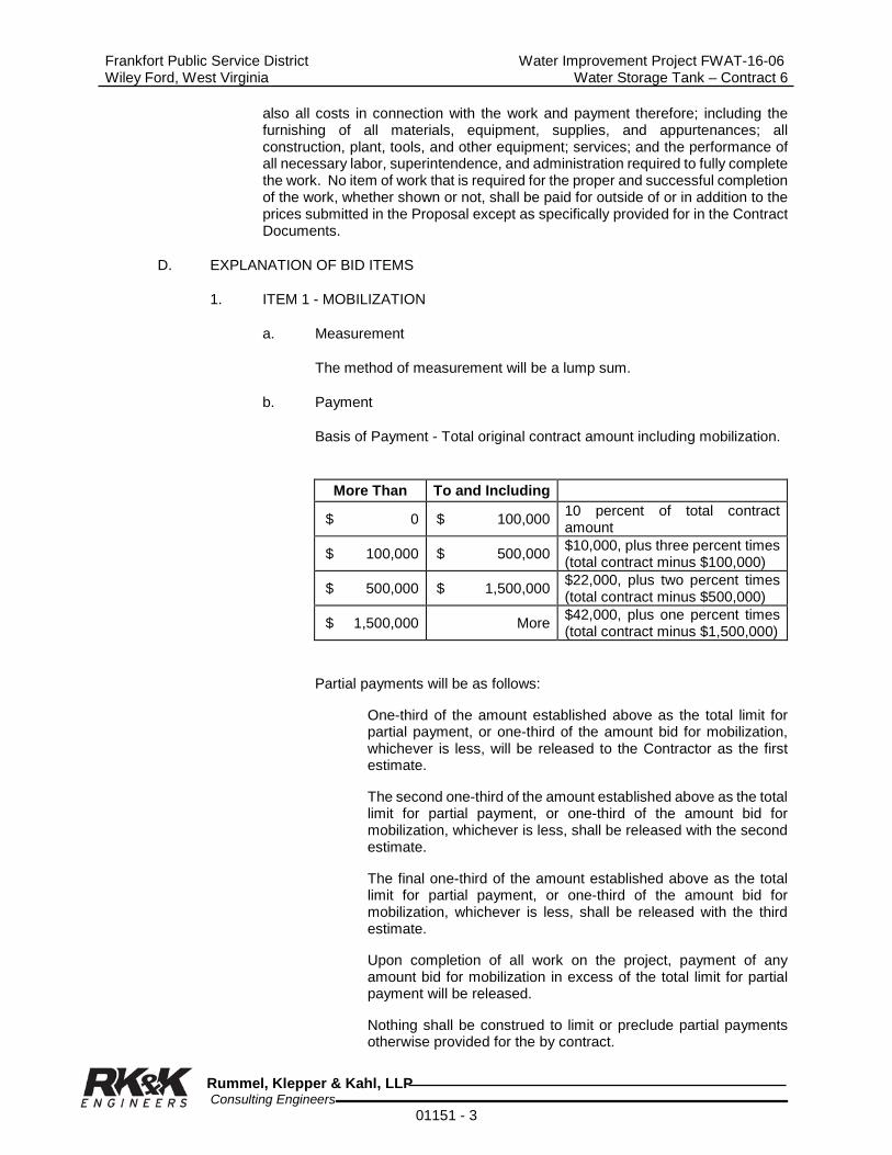
Frankfort Public Service District Water Improvement Project FWAT-16-06 Wiley Ford, West Virginia Water Storage Tank – Contract 6
Rummel, Klepper & Kahl, LLP Consulting Engineers 01151 - 3
also all costs in connection with the work and payment therefore; including the furnishing of all materials, equipment, supplies, and appurtenances; all construction, plant, tools, and other equipment; services; and the performance of all necessary labor, superintendence, and administration required to fully complete the work. No item of work that is required for the proper and successful completion of the work, whether shown or not, shall be paid for outside of or in addition to the prices submitted in the Proposal except as specifically provided for in the Contract Documents.
D. EXPLANATION OF BID ITEMS
1. ITEM 1 - MOBILIZATION
a. Measurement
The method of measurement will be a lump sum.
b. Payment
Basis of Payment - Total original contract amount including mobilization.
Partial payments will be as follows:
One-third of the amount established above as the total limit for partial payment, or one-third of the amount bid for mobilization, whichever is less, will be released to the Contractor as the first estimate.
The second one-third of the amount established above as the total limit for partial payment, or one-third of the amount bid for mobilization, whichever is less, shall be released with the second estimate.
The final one-third of the amount established above as the total limit for partial payment, or one-third of the amount bid for mobilization, whichever is less, shall be released with the third estimate.
Upon completion of all work on the project, payment of any amount bid for mobilization in excess of the total limit for partial payment will be released.
Nothing shall be construed to limit or preclude partial payments otherwise provided for the by contract.
More Than To and Including
$ 0 $ 100,000 10 percent of total contract amount
$ 100,000 $ 500,000 $10,000, plus three percent times (total contract minus $100,000)
$ 500,000 $ 1,500,000 $22,000, plus two percent times (total contract minus $500,000)
$ 1,500,000 More $42,000, plus one percent times (total contract minus $1,500,000)

Frankfort Public Service District Water Improvement Project FWAT-16-06 Wiley Ford, West Virginia Water Storage Tank – Contract 6
Rummel, Klepper & Kahl, LLP Consulting Engineers 01151 - 4
No deduction will be made, nor will any increase be made, in the lump sum mobilization item amount regardless of decreases or increases in the final total contract amount or for any other cause.
2. ITEM 2 – ACCESS ROAD AND TANK SITE PREPARATION
a. Measurement
No measurement for this lump sum item will be made.
b. Payment
Payment for these items will be made at lump sum price which will include labor, supervision, tools, equipment, and materials necessary to construct access road complete and prepare tank site complete per plans and specifications, which shall include clearing and grubbing, excavation, handling and disposal of excess material, grading, filter fabric, crusher run limestone, graded limestone, diversion ditches with rip rap lining, overflow drain, underdrain, ditches, stone check dams, rip-rap, spreader, furnish and place stone on site, culverts and outlet protection, sediment and erosion control, seeding and mulching, and all incidentals necessary for construction of access road and preparation of tank site per plans and specifications.
3. ITEM 3 – YARD PIPING
a. Measurement
No measurement for this lump sum item will be made.
b. Payment
Payment for this item will be made at lump sum price which will include all labor, supervision, tools, equipment, and materials necessary for yard piping including connection to existing pipeline, excavation, backfill, bedding, valve vault and drain, water line, valves, installation of tank drain lines, valves and connection to tank, cleaning pipe, testing, disinfection, concrete flume from tank to outlet, and all incidentals necessary for yard piping per plans and specifications.
4. ITEM 4 –WATER STORAGE TANK
a. Measurement
No measurement for this lump sum item will be made.
b. Payment
Payment will be for either glass coated, bolted tank or welded steel tank with self-supporting roof and shall include painting and foundation preparation per plans and specifications as required for respective tank. Payment for this item will be made at the lump sum price which will include all labor, tools, material, and equipment necessary to construct a steel water storage tank including, excavation for foundation, construction of foundation and overflow flume, concrete foundation, concrete floor, gravel

Frankfort Public Service District Water Improvement Project FWAT-16-06 Wiley Ford, West Virginia Water Storage Tank – Contract 6
Rummel, Klepper & Kahl, LLP Consulting Engineers 01151 - 5
floor sub-base, expansion material and sealant, installation of tank, installation of tank appurtenances, sealing around base, connection of tank to piping, testing, cleaning and disinfection of tank, and placing it in service.
5. ITEM 5 – CATHODIC PROTECTION SYSTEM
a. Measurement
No measurement for this lump sum item will be made.
b. Payment
Payment for this item will be made at lump sum price which will include all labor, supervision, tools, equipment, and materials necessary to install a water tank cathodic protection system in accordance with the specification.
6. ITEM 6 – ROCK RIP RAP
a. Measurement
Riprap shall be measured on a cubic yard basis for the dimensions shown on the plans or approved by the Engineer. At the direction of Engineer, cubic yards may be computed from tonnage weight tickets using 90 pcf for in place density of rip-rap.
b. Payment
Payment for furnishing or placing the rip rap at the unit price bid shall include labor, equipment, and material for grading, filter fabric, furnishing and placing rip rap, and necessary work to complete the item as shown on the drawings or approved by the Engineer. Specific size of rip-rap shall be approved by Engineer.
7. ITEM 7 – 6’ HIGH CHAIN LINK FENCE W/ 3 STRAND BARBED WIRE (6 ft.)
a. Measurement
Measurement for this item shall be per linear foot of fence installed, excluding gates.
b. Payment
Payment for this item shall be at the unit price per linear foot of fence installed which shall include all labor, tools, materials, equipment, excavation, and concrete required to install the fence as described in plans and specifications.
8. ITEM 8 – 14’ CHAIN LINK GATE W/3 STRAND BARBED WIRE
a. Measurement
No measurement for this lump sum item will be required.
b. Payment

Frankfort Public Service District Water Improvement Project FWAT-16-06 Wiley Ford, West Virginia Water Storage Tank – Contract 6
Rummel, Klepper & Kahl, LLP Consulting Engineers 01151 - 6
Basis of payment will be at lump sum price which shall include all labor, tools, equipment and materials to install the gate per specifications and plans, which shall consist of two 7’ gates for an opening width of 14 ft. with all appurtenances as shown on plans and specifications.
END OF SESSION

Frankfort Public Service District Water Improvement Project FWAT-16-06 Wiley Ford, West Virginia Water Storage Tank – Contract 6
Rummel, Klepper & Kahl, LLP Consulting Engineers
01170 - 1
SECTION 01170
SPECIAL PROVISIONS
PART 1 - GENERAL
1.01 GENERAL OBLIGATIONS OF THE CONTRACTOR
A. General obligations of the Contractor shall be as set forth in the Bid Documents. All incidental work and expense in connection with the completion of work under the Contract will be considered a subsidiary obligation of the Contractor and all such costs shall be included in the appropriate items in the Fee Schedule in connection with which the costs are incurred.
1.02 SITE INVESTIGATION
A. The Contractor shall satisfy himself as to the conditions existing within the project area; the type of equipment required to perform the work; the character, quality and quantity of the subsurface materials, solids and grit to be encountered insofar as this information is reasonably ascertainable from an inspection of the site, as well as from information presented by the Drawings and related Sections. Any failure of the Contractor to acquaint himself with the available information will not relieve him from the responsibility for estimating properly the difficulty or cost of successfully performing the work. The Owner assumes no responsibility for any conclusions or interpretation made by the Contractor on the basis of the information made available by the Owner.
1.03 COORDINATION WITH LOCAL AGENCIES
A. Supply the Local Law Enforcement, Fire Department(s), School Board and the Public Service District with the following information.
1. A list of streets and intersections where work will be in progress to be supplied at intervals as required by the Engineer.
2. Areas where approved detours and street closings are in effect.
3. Immediate notification of any sewer or appurtenant breaks.
1.04 PUBLIC UTILITIES AND STRUCTURES
A. Notify utility companies of any damage to their utilities resulting from inspection and cleaning operations.
B. If, during the course of the work, the Contractor for whatever reason causes the existing utilities in the area to fail, the Contractor shall restore service in the shortest possible time, working around the clock if necessary. The Contractor will complete repairs to the satisfaction of the utility owner and will cooperate with the owner in supplying emergency service to local residents.
C. Assume full responsibility for the protection of all buildings, structures, and utilities, public or private, including poles, signs, services to buildings, utilities in the street, gas pipes, water pipes, hydrants, sewers, drains and electric and telephone cables, whether or not they are shown on the Drawings. Carefully support and protect all such structures and utilities from injury of any kind.

Frankfort Public Service District Water Improvement Project FWAT-16-06 Wiley Ford, West Virginia Water Storage Tank – Contract 6
Rummel, Klepper & Kahl, LLP Consulting Engineers
01170 - 2
Immediately repair, at no additional expense to the Owner, property owner or utility, any damage resulting from the operations.
D. Assistance will be given the Contractor in determining the location of existing services. The Contractor, however, shall bear full responsibility for obtaining all locations of underground sewers and appurtenances. Maintain services to buildings and pay costs or charges resulting from damage thereto.
1.05 PROGRESS SCHEDULE
A. Submit a progress schedule before starting any work, as specified herein.
B. Review the progress schedule with the Engineer on a monthly basis or more frequently as required by the Engineer. The progress schedule shall be adjusted as required.
1.06 ENVIRONMENTAL PROTECTION, CLEANUP AND DISPOSAL
A. Provide for the flow of sewers interrupted during the progress of the work, and immediately cart away and remove all offensive matter. Discuss the entire procedure of maintaining existing flow with the Engineer well in advance of the interruption of any flow. Take sufficient precautions during operations to minimize the run-off of polluting substances such as spoils, grit, debris, wastewater, fuels and oils into the supplies and surface waters of the State.
B. During the course of the work, keep the site of operations as clean and neat as possible. Dispose of all residues resulting from the inspection work and, at the conclusion of the work, remove and haul away any temporary structures and any other refuse remaining from the operations and leave the entire site of the work in a neat and orderly condition.
C. In order to prevent environmental pollution arising from the activities related to the performance of this Contract, comply with all applicable Federal, State and local laws and regulations concerning waste material disposal, as well as the specific requirements stated in this Section and in other related Sections. The Contractor shall also be required to comply with the requirements and regulations of the debris disposal facility.
D. Disposal of waste material and other debris removed during cleaning operations in wetlands, stream corridors and plains is strictly prohibited even if the permission of the property owner is obtained. Any violation of this restriction by the Contractor, his subcontractors or any person employed by these companies, will be brought to the immediate attention of the responsible regulatory agencies, with a request that appropriate action be taken against the offending parties. The Contractor will be required to remove the fill and restore the area impacted at no increase in the Contract Price.
E. The Contractor shall immediately remove from the site and legally dispose all debris removed from existing sewers and appurtenances cleaned and inspected under this Contract. At no time shall these materials be stacked around the access port or surrounding area. Such material should be considered non-hazardous and the costs for disposing of it shall be included in the unit pricing for sewer cleaning, testing and disposal bid by the Contractor.
Frankfort Public Service District Water Improvement Project FWAT-16-06 Wiley Ford, West Virginia Water Storage Tank – Contract 6
Rummel, Klepper & Kahl, LLP Consulting Engineers
01170 - 3
F. The Engineer will notify the Contractor in writing of any non-compliance with the foregoing provisions or of any environmentally objectionable acts and corrective action to be taken. State or local agencies responsible for verification of certain aspects of the environmental protection requirements shall notify the Contractor in writing, through the Engineer, of any non-compliance with State or local requirements. After receipt of such notice from the Engineer or from the regulatory agency through the Engineer, immediately take corrective action. Such notice, when delivered to the Contractor or his authorized representative at the site of the work, shall be deemed sufficient for the purpose. If the Contractor fails or refuses to comply promptly, the Engineer may issue an order stopping all or part of the work until satisfactory corrective action has been taken. No part of the time lost due to any such stop orders shall be made the subject of a claim for extension of time or for excess costs or damages by the Contractor unless it is later determined that the Contractor was in compliance.
1.07 PERMITS AND NOTIFICATIONS
A. Obtain all necessary permits required for proper execution of the project. Fill out all forms and furnish all drawings required to obtain the permits. A copy of each permit shall be submitted to the Engineer. All fees associated with these permits shall be paid by the Contractor as part of the work. Work shall not commence on any phase of the work requiring a permit until the permit is obtained.
B. The Contractor shall be responsible for notifying local agencies of their intent to conduct inspection operations. The Contractor should coordinate work with these entities to ensure the owner is aware that work will be taking place near these facilities and to identify any facilities of concern that may not have been identified above.
C. The Contractor will also be responsible for contacting local businesses and individuals when encroaching onto private property.
1.08 NOTICE TO PROPERTY OWNERS
A. Do not enter or occupy private land outside of rights-of-way, except by permission of the landowner or supervising authority.
1.09 CARE AND PROTECTION OF PROPERTY AND WORK
A. Be responsible for the preservation of all public and private property and use every precaution necessary to prevent damage thereto. If any direct or indirect damage is done to public or private property by or on account of any act, omission, neglect, or misconduct in the execution of the work on the part of the Contractor, restore such property to a condition similar or equal to that existing before the damage was done, or make good the damage in other manner acceptable to the Engineer at no additional cost to the Owner.
B. From the commencement of the work until its completion and acceptance by the Owner, the Contractor shall be solely responsible for the care of the work, and all injury or damage to the same, from whatever cause, shall be repaired by him at his own expense, before the final estimate is made. The Contractor shall provide suitable means of protection for all materials intended to be used in the work in progress, as well as for completed work.

Frankfort Public Service District Water Improvement Project FWAT-16-06 Wiley Ford, West Virginia Water Storage Tank – Contract 6
Rummel, Klepper & Kahl, LLP Consulting Engineers
01170 - 4
1.10 OPEN SEWERS
A. Adequately safeguard all open openings and other access points by providing temporary barricades, caution signs, lights and other means to prevent accidents to persons and damage to property. The size of the opening will be according to the particular feature. If the opening becomes a hazard, or if it excessively restricts traffic at any point, the Engineer may require special inspection procedures such as limiting the hours of operation or installing alternate traffic control measures.
B. Take precautions to prevent injury to the public due to open access ports and manholes. Provide adequate light at all openings, equipment, or other obstacles that could be dangerous to the public at all times. No access opening to the sewer system will be left unsupervised by the Contractor.
1.11 COOPERATION WITHIN THIS CONTRACT
A. All firms or persons authorized to perform any work under this Contract shall cooperate with the Contractor and Subcontractors or trades and assist in incorporating the work of other trades where necessary or required.
1.12 WATER FOR OPERATIONS
A. In locations where public water supply is available, the Contractor may be allowed to use water without charge for cleaning purposes with approval of Frankfort PSD.
B. The express approval of the Frankfort PSD shall be obtained before water is used. Waste of water shall be sufficient cause for withdrawing the privilege of unrestricted use. Hydrants shall only be operated under the supervision of the PSD's personnel.
C. If water restrictions are in force, the Contractor shall supply his own source of water that shall be acceptable to the Engineer.
D. When drawing water for cleaning purposes, the Contractor shall use caution at all times so as to prevent potential contamination of the Owner's water supply and distribution system. The PSD may require that a backflow preventer be utilized.
E. The Contractor shall supply a working reduced pressure backflow preventer and flow meter for each hydrant utilized during work. At the end of the work, the Contractor shall furnish a tabulation of the total gallons of water utilized each month during the course of the Contract.
F. The Contractor must exercise extreme care when opening and closing PSD hydrants. All hydrants must be opened and closed SLOWLY to prevent damage.
G. Prior to the start of work on any sewer segment, the Contractor shall submit a water use plan for approval by the Engineer. The plan shall detail the location of hydrants to be utilized, the routing of hoses across sidewalks and roadways, and the means to be used to protect hoses from traffic and pedestrians from tripping hazards as well as to minimize the occurrence of water hammer.

Frankfort Public Service District Water Improvement Project FWAT-16-06 Wiley Ford, West Virginia Water Storage Tank – Contract 6
Rummel, Klepper & Kahl, LLP Consulting Engineers
01170 - 5
1.13 TEMPORARY FACILITIES
A. Furnish temporary light and power, complete with wiring, lamps and similar equipment as required to adequately light all work areas and with sufficient power capacity to meet the reasonable needs to complete work during evening hours.
B. Provide self-contained, single occupant toilet units of the chemical, aerated recirculation, or combustion type, properly vented and fully enclosed in a fiberglass or other approved non-absorbent shell.
C. Completely remove all temporary materials and facilities when their use is no longer required. Clean and repair damage caused by temporary installations or use of temporary facilities.
PART 2 - PRODUCTS (NOT USED)
PART 3 - EXECUTION
3.01 PROTECTION OF STREAMS AND SURFACE WATERS
A. Take all precautions to prevent, or reduce to a minimum, any damage to any stream or surface water from pollution by debris, sediment or other material, or from the manipulation of equipment and/or materials in or near such streams. Water that has been used for washing or cleaning, or that contains oils or sediments that will reduce the quality of the water in the stream, shall not be returned to the stream.
B. Do not discharge waters from cleaning operations directly into any live or intermittent stream, channel, wetlands, surface water or any storm sewer.
C. Take all preventative measures to avoid spillage of solid and liquid materials removed from the sewer system. In the event of any spillage, prompt remedial action shall be taken in accordance with the West Virginia Department of Environmental Protection. The Contractor shall be liable for any penalties or fines for discharges or occurrences related to contract work.
3.02 PROTECTION OF LAND RESOURCES
A. Restore land resources within the project boundaries and outside the limits of permanent work to a condition, after completion of work that will appear to be natural or matches the conditions existing prior to the start of work. Confine all activities to the general areas shown on the Drawings.
B. Do not deface, injure, or destroy trees or shrubs, nor remove or cut them without prior approval. No ropes, cables, or guys shall be fastened to or attached to any existing nearby trees for anchorage unless specifically authorized by the Engineer. Where such special emergency use is permitted, first wrap the trunk with a sufficient thickness of burlap or rags over which softwood cleats shall be tied before any rope, cable, or wire is placed. The Contractor shall in any event be responsible for any damage resulting from such use.
C. Before beginning operations near them, protect trees that may possibly be defaced, bruised, injured, or otherwise damaged by equipment, by placing

Frankfort Public Service District Water Improvement Project FWAT-16-06 Wiley Ford, West Virginia Water Storage Tank – Contract 6
Rummel, Klepper & Kahl, LLP Consulting Engineers
01170 - 6
boards, planks, or poles around them. Monuments and markers shall be protected similarly.
D. Any trees or other landscape features scarred or damaged by the Contractor's equipment or operations shall be restored as nearly as possible to their original condition. The Engineer will decide the method of restoration to be used and whether damaged trees shall be treated and healed or removed, disposed of and replaced in kind.
1. All scars made on trees by equipment or during operations shall be coated as soon as possible with an approved tree wound dressing.
E. Unless specifically shown on plans, no arrangements will be made for any means of access to the right-of-ways or construction strips by the Owner. The Contractor shall therefore be required to make his own arrangements for access to the work within these points and copy of these arrangements shall be furnished to the Owner.
3.03 PROTECTION OF AIR QUALITY
A. Burning - The use of burning at the project site for the disposal of refuse and debris will not be permitted.
3.04 NOISE CONTROL
A. Make every effort to minimize noises caused by the operations. Equipment shall be equipped with silencers or mufflers designed to operate with the least possible noise in compliance with Federal and State regulations.
3.05 MAINTENANCE OF POLLUTION CONTROL FACILITIES DURING CONSTRUCTION
A. Maintain all facilities constructed for pollution control as long as the operations creating the particular pollutant are being carried out or until the material concerned has become stabilized to the extent that pollution is no longer being created.
3.06 LINES GRADES AND ELEVATIONS
A. The Contractor shall furnish the field stakeout of all necessary lines, grades, and elevations to complete the work as shown on the plans and specifications. Horizontal and vertical control data will be furnished by the Engineer. Such stakeouts must be approved by the Engineer, and corrected if and as necessary, before the Contractor proceeds with construction. The Contractor shall have no claims for damages or extra compensation due to delays originating from unapproved stakeouts and/or necessary corrections thereto.
B. The Contractor shall preserve and maintain in proper condition all stakes, grade-boards and lines until authorized to remove same.
C. Cut sheets for all utility lines shall be provided by the Contractor for the
Engineer's approval before the start of any excavation for utility lines. The cut sheets shall include profile information along the existing ground, along the centerline of the utility at intervals not exceeding 50 feet and at the location of all proposed structures. The cut sheets shall also include elevations of the finished utility invert and the cut from proposed invert grade of the utility to the existing ground line.
3.07 INSPECTION
Frankfort Public Service District Water Improvement Project FWAT-16-06 Wiley Ford, West Virginia Water Storage Tank – Contract 6
Rummel, Klepper & Kahl, LLP Consulting Engineers
01170 - 7
A. The Engineer will appoint such persons, contingent upon approval of Owner and Funding Agency, as he may deem necessary to inspect the materials furnished or to be furnished, and the work done under the Contract, and to see that the same is proceeding in accordance with the Contract Documents. Work and material will be inspected promptly, but, if for any reason, delay should occur, the Contractor shall have thereby no claim for damages or extra compensation.
B. The Inspector is authorized to direct the attention of the Contractor to any failure of work or materials to conform to the requirements of the Contract Documents. The Inspector is authorized to reject materials, or suspend the work until any questions at issue can be referred to and decided by the Engineer.
C. The Inspector is not authorized to revoke, alter or waive any requirements of the
Contract, nor to direct the Contractor to undertake extra work which is beyond the scope of the Contract or for which the Contractor may subsequently claim extra compensation or extensions of time, nor to approve or accept any portion of the completed work.
D. The Inspector shall in no case act as foreman or perform other duties for the
Contractor, nor interfere with the management of the work. Advice which the Inspector may offer the Contractor shall not bind the Engineer in any way, nor release the Contractor from fulfilling all of the terms of the Contract.
E. Any disagreement between the Contractor and Inspector will be immediately
directed by the Inspector to the Engineer for decision. The Engineer will render his decision promptly, and should the Contractor refuse to comply, the Engineer will suspend the work, and direct the Inspector to leave the site. Any work performed by the Contractor during the Inspector's absence will be neither accepted nor paid for.
F. The Contractor shall furnish the Engineer with every reasonable facility for
ascertaining whether or not the work performed and materials used are in accordance with the requirements and intent of the Contract Documents. If the Engineer so requests, the Contractor shall, at any time before acceptance of the work, remove or uncover such portions of the finished work as may be directed. After examination, the Contractor shall restore said portions of the work to the standard required by the Specifications. Should the work thus exposed or examined prove acceptable, the cost of uncovering, or removing, and the replacing of the covering or making good of the parts removed will be paid as extra work, but should the work so exposed or examined prove unacceptable, the cost of uncovering or removing, and the replacing of the covering or making good of the parts removed, shall be the Contractor's sole expense.
G. The Contractor shall pay for all necessary inspection costs incurred by any other
agency than the Owner, such as public service utility company, governmental agency, or other agency whose jurisdiction affects the work in any manner, unless otherwise specified herein.
END OF SECTION

Frankfort Public Service District Water Improvement Project FWAT-16-06 Wiley Ford, West Virginia Water Storage Tank – Contract 6
Rummel, Klepper & Kahl, LLP Consulting Engineers
01170 - 8
THIS PAGE LEFT BLANK
Frankfort Public Service District Water Improvement Project FWAT-16-06 Wiley Ford, West Virginia Water Storage Tank – Contract 6
Rummel, Klepper & Kahl, LLP Consulting Engineers
01200 - 1
SECTION 01200
PROJECT MEETINGS
PART 1 - GENERAL
1.01 SUMMARY
A. Section Includes:
1. Preconstruction Conference
2. Progress Meetings
3. Pre-Installation Meeting
4. Coordination Meetings
B. Related Requirements
1. Section 01700 - Project Closeout
1.02 PRECONSTRUCTION CONFERENCE
A. Engineer will schedule and administer preconstruction conference.
B. Engineer will administer site mobilization conference at Project site for clarification of Owner and Contractor responsibilities in use of site and for review of administrative procedures.
C. Agenda: Discuss items of significance that could affect progress including such topics as:
1. Tentative construction schedule
2. Critical work sequencing
3. Designation of responsible personnel
4. Procedures for processing field decisions and Change Orders
5. Procedures for processing Applications for Payment
6. Distribution of Contract Documents
7. Submittal of Shop Drawings, Product Data and Samples
8. Preparation of record documents
9. Use of the premises
10. Office, work and storage areas
11. Equipment deliveries and priorities
12. Safety procedures
13. First aid

Frankfort Public Service District Water Improvement Project FWAT-16-06 Wiley Ford, West Virginia Water Storage Tank – Contract 6
Rummel, Klepper & Kahl, LLP Consulting Engineers
01200 - 2
14. Security
15. Housekeeping
16. Working hours
17. Procedures for testing
18. Requirements for start-up of equipment
1.03 SUPERINTENDENT’S MEETINGS
A superintendent’s meeting will be held at beginning of every week by Contractor which shall cover planned work for upcoming week stressing any unusual aspects of planned work as well as safety. The Engineer and representatives of any utilities to be affected shall be invited to the meeting.
1.04 PROGRESS MEETINGS
A. Engineer will schedule and administer Progress meetings throughout progress of the work at least once a month or as deemed necessary by Engineer. Times and dates shall be agreed upon by the Engineer, Owner and Contractor.
B. Project meetings shall be held at Engineer’s Project Office.
C. Attendance: Contractors’ Project Manager and Job Superintendent, Owner and Engineer as appropriate to agenda topics for each meeting. Major subcontractors and suppliers shall attend when requested by the Engineer.
D. The first progress meeting shall be held soon after start of work. The Contractor, having previously carefully examined Drawings and Specifications, shall present to Engineer any questions that have arisen.
E. Agenda
1. Review and correct or approve minutes of the previous progress meeting.
2. Review other items of significance that could affect progress.
3. Include topics for discussion as appropriate to the current status of the Project.
4. Construction Schedule: Review progress since the last meeting. Determine where each activity is in relation to the Construction Schedule, whether on time or ahead or behind schedule. Determine how construction behind schedule will be expedited; secure commitments from parties involved to do so. Discuss whether schedule revisions are required to ensure that current and subsequent activities shall be completed within the Contract Time.
5. Review the present and future needs of each entity present, including such items as:
a. Interface requirements
Frankfort Public Service District Water Improvement Project FWAT-16-06 Wiley Ford, West Virginia Water Storage Tank – Contract 6
Rummel, Klepper & Kahl, LLP Consulting Engineers
01200 - 3
b. Time
c. Sequences
d. Deliveries
e. Off-site fabrication problems
f. Access
g. Site utilization
h. Temporary facilities and services
i. Hours of work
j. Hazards and risks
k. Housekeeping
l. Quality and work standards
m. Change orders
n. Documentation of information for payment requests
1.05 PRE-INSTALLATION CONFERENCE
A. When required in individual Specification Sections, convene a pre-installation conference prior to commencing work of the Section.
B. Require attendance of entities directly affecting, or affected by, work of the Section.
C. Review conditions of installation, preparation and installation procedures, and coordination with related work.
D. Review the progress of other construction activities and preparations for the particular activity under consideration at each pre-installation conference, including requirements for:
1. Contract Documents
2. Options
3. Related Change Orders
4. Purchases
5. Deliveries
6. Shop Drawings, Product Data and quality control samples
7. Possible conflicts
8. Compatibility problems
9. Time schedules
10. Weather limitations
11. Manufacturer’s recommendations

Frankfort Public Service District Water Improvement Project FWAT-16-06 Wiley Ford, West Virginia Water Storage Tank – Contract 6
Rummel, Klepper & Kahl, LLP Consulting Engineers
01200 - 4
12. Compatibility of materials
13. Acceptability of substrates
14. Temporary facilities
15. Space and access limitations
16. Governing regulations
17. Safety
18. Inspection and testing requirements
19. Required performance results
20. Recording requirements
21. Protection
1.06 ADMINISTERING MEETINGS
The Engineer will schedule, administer, record and report all meetings. Minutes will be distributed within five business days after each meeting.
1.07 COORDINATION MEETINGS
It is strongly suggested that the General Contractor hold weekly meetings, every Monday morning, with the sub-contractors to coordinate up-coming work and to review progress.
PART 2 - PRODUCTS
Not Used
PART 3 - EXECUTION
Not used.
END OF SECTION

Frankfort Public Service District Water Improvement Project FWAT-16-06 Wiley Ford, West Virginia Water Storage Tank – Contract 6
Rummel, Klepper & Kahl, LLP Consulting Engineers
01300 - 1
SECTION 01300
SUBMITTALS
PART 1 - GENERAL
1.01 SUMMARY
A. Section Includes
1. Administrative Submittals
2. Shop Drawings (submit 8)
3. Product data
4. Samples
5. Manufacturer’s equipment certification
6. Construction photographs (minimum of six 8”x10”’s monthly)
7. Submittal procedures
B. Related Requirements
1. Section 01010 - General Requirements
2. Section 01027 - Applications for Payment
3. Section 01600 - Material and Equipment
4. Section 01700 - Project Closeout
1.02 PREPARATION OF SUBMITTAL
A. Provide a permanent label, title block or transmittal letter for each submittal for identification. Indicate the name of the entity that prepared each submittal on the label or title block.
B. Include the following information on the label or transmittal letter for processing and recording action taken (see form attached to the back of this section):
1. Project Title:
2. Date:
3. Rummel, Klepper & Kahl, LLP, Engineer, 159 Plaza Drive, Keyser, West Virginia 26726
4. Name and address of Contractor
5. Name and address of subcontractor
6. Name and address of supplier

Frankfort Public Service District Water Improvement Project FWAT-16-06 Wiley Ford, West Virginia Water Storage Tank – Contract 6
Rummel, Klepper & Kahl, LLP Consulting Engineers
01300 - 2
7. Name of manufacturer
8. Number and title of appropriate Specification Section
9. Drawing and title of appropriate Specification Section
10. Contract Name:
C. Provide a space approximately 4" x 4" on the label or beside the title block on Shop Drawings to record the Contractor’s review and approval prior to submitting to the Engineer. Also provide 4” x 4” space for Engineers approval.
D. Submittals that fail to conform to these requirements may be cause for being returned without any action for correction by the Contractor. No extension of Contract Time will be authorized because of submittals being returned without action because of failure to comply with these regulations.
E. Package each submittal appropriately for transmitting and handling.
F. Identify Project, Contractor, subcontractor, major supplier; identify pertinent Drawing sheet and detail number, and Specification Section number; identify deviations from Contract Documents. Provide space for Contractor and Engineer review stamps.
1.03 COORDINATION AND SCHEDULING
A. Schedule: Within twenty-one (21) working days of Execution of the Contract, submit a schedule for all submittals; indicate the date of submittals and date of return. The first application for payment will not be approved until an acceptable schedule is received by the Engineer.
B. Coordination: Coordinate preparation and processing of submittals with performance of construction activities. Transmit each submittal sufficiently in advance of performance of related construction activities to avoid delay.
C. Coordinate each submittal with fabrication, purchasing, testing, delivery, other submittals and related activities that require sequential activity.
D. Coordinate transmittal of different types of submittals for related elements of the work so processing will not be delayed by the need to review submittal concurrently for coordination.
E. Schedule a minimum of three (3) weeks for handling and review for each submittal. Schedule additional time for review if submittal must be coordinated with subsequent submittals.
F. Schedule a minimum of ten (10) working days for review of each submittal by the Engineer. If the submittal must be delayed for coordination, the Engineer will inform the Contractor within the ten (10) working days scheduled for review.
G. No extension of Contract Time will be permitted because of failure to transmit submittals sufficiently in advance to permit processing on a timely basis.
1.04 ADMINISTRATIVE SUBMITTALS
A. Refer to other Division 1 Sections and other Contract Documents for

Frankfort Public Service District Water Improvement Project FWAT-16-06 Wiley Ford, West Virginia Water Storage Tank – Contract 6
Rummel, Klepper & Kahl, LLP Consulting Engineers
01300 - 3
requirements for administrative submittals. Such submittals include, but are not limited to:
1. Permits
2. Applications
3. Performance and payment bonds
4. Insurance certificates
5. List of subcontractors
6. Schedules
7. Daily construction reports
8. Statement by Contractor and Employees (Act 34)
9. Installation certificates
B. The Schedule of Values submittal is included in Section “Applications for Payment”.
1.05 SHOP DRAWINGS
A. The Contractor shall submit to the Engineer shop drawings and properly completed equipment certification forms as required. The Engineer may elect not to review shop drawings for equipment until a properly completed certification form has been received for that piece of equipment.
B. At the time of submission, the Contractor shall call to the Engineer’s attention, in writing, any deviations that the shop drawings may have from the requirements of the Drawings and Specifications.
C. If more than one resubmittal of a shop drawing is required due to the Contractor’s submission of products that do not meet the contract requirements, the Owner reserves the right to be compensated by the Contractor for costs incurred to perform additional reviews.
D. The Contractor shall submit the shop drawings marked as either “Submitted as Specified” or “Submitted as Equal to Specified”.
1. Where any article is specified by trade name or name of manufacturer with the clause “or equal”, it is intended to establish the quality of the article. If the Contractor proposes to use material or equipment of another manufacturer as an “or equal” to the specified material or equipment, all shop drawings shall conform to the following requirements, conditions and procedures:
a. Substitution of equipment or materials other than those specified will be permitted, providing, in the opinion of the Engineer, such equipment or material is equal to or better than that specified. The decision of the Engineer with respect to approval or disapproval of any material or equipment proposed to be substituted as an “or equal” is final. The Contractor shall have no claim of any sort by reason of such decision.

Frankfort Public Service District Water Improvement Project FWAT-16-06 Wiley Ford, West Virginia Water Storage Tank – Contract 6
Rummel, Klepper & Kahl, LLP Consulting Engineers
01300 - 4
b. If the Contractor proposes to substitute materials or equipment as “or equal” to those specified, it shall be his responsibility to furnish complete, specific, detailed information from the manufacturer or supplier of the material or equipment he proposes to furnish, in which the requirements of the Contract Specifications are shown to be met. This shall consist of a point by point comparison of the Contract Specification requirements with the material or equipment proposed to be furnished. In the event the Contract Specifications mention a model number or other designation and manufacturer in lieu of the detailed description and manufacturer, a point by point comparison of the equipment specified under the Contract and that proposed to be substituted shall be furnished. The burden of responsibility to furnish this information is with the Contractor. If incomplete or irrelevant data is submitted as evidence of compliance with the Contract Specifications, the data will be returned and the request for approval will be denied.
c. All suppliers and sub-contractors, including those listed as approved sources, must comply with all requirements as setforth in plans and specifications.
E. All shop drawing information must be submitted in a timely fashion to allow a thorough review by the Engineer and to ensure that delivery of the equipment coincides with the construction schedule. Failure of the shop drawings to comply with the specifications, requiring subsequent resubmittals, may adversely affect the construction schedule. Any such delays are solely the responsibility of the Contractor. The Owner and Engineer will not entertain or approve any claims by the Contractor for additional costs or extensions of contract time based on failure to obtain shop drawing approvals.
F. The Engineer’s comments will include specific details as to what or where the shop drawings do not comply with the Drawings or Contract Specifications. The Engineer shall review only such data and details as are transmitted to him by the Contractor. The Contractor shall coordinate between all suppliers and subcontractors.
G. Copies of the approved shop drawings will be included in operation and maintenance manuals.
H. The Engineer will retain two copies of each shop drawing.
I. The Contractor’s attention is specifically directed to the fact that no items shall be fabricated, nor equipment or materials ordered, nor any construction performed prior to approval by the Engineer of shop drawings applicable thereto.
1.06 PRODUCT DATA
A. Submit only pages which are pertinent; mark each copy of standard printed data to identify pertinent products, referenced to Specification section and article number. Show reference standards, performance characteristics and capacities, wiring and piping diagrams and controls, component parts, finishes, dimensions, and required clearances.
B. Modify manufacturers’ standard schematic drawings and diagrams to supplement standard information and to provide information specifically applicable to the work. Delete information not applicable.

Frankfort Public Service District Water Improvement Project FWAT-16-06 Wiley Ford, West Virginia Water Storage Tank – Contract 6
Rummel, Klepper & Kahl, LLP Consulting Engineers
01300 - 5
C. Manufacturers’ Instructions: When required in individual Specification Sections, submit manufacturers’ printed instructions for delivery, storage, assembly, installation, start-up, adjusting and finishing in quantities specified for product data.
1.07 SAMPLES
A. Submit full range of manufacturers’ standard finishes except when more restrictive requirements are specified, indicating colors, textures and patterns, for Engineer selection.
B. Submit samples to illustrate functional characteristics of products, including parts and attachments.
C. Approved samples which may be used in the work are indicated in the Specification Sections.
D. Label each sample with identification required for transmittal letter.
E. Provide field samples of finishes at Project, at location acceptable to Engineer, as required by individual Specification Sections. Install each sample complete and finished. Acceptable finishes in place may be retained in completed work.
1.08 MANUFACTURERS’ EQUIPMENT CERTIFICATION
A. A list of equipment for which the manufacturers’ certification is required is included in this specification section.
B. At the time of submitting Shop Drawings, submit a certification in the form provided at the end of this section or as provided at the end of each specific equipment or system specification section, from each manufacturer of the equipment or system listed below attesting that the manufacturer has examined the Contract Drawings and Specifications and that the proposed equipment, component, or system meets or exceeds Contract Specifications, is suitable for its intended purpose and installation, and will provide satisfactory performance at the design criteria specified.
C. Applicable Equipment:
1. NONE REQUIRED
1.09 CONSTRUCTION PHOTOGRAPHS
A. The Contractor shall submit monthly to the Engineer a minimum of six 8"x10" color photographs, with negatives, taken on or about the first of each month showing the actual construction progress of the work. Two prints of each negative are necessary, but the negatives should be sufficient in number to properly record the work. If acceptable to Funding Agency and Owner, digital photos will suffice.
B. Photographs shall be taken using a good quality camera and lens. Film size shall be 35 mm or larger. Prints shall be color, in focus, and of good color resolution; rejected photographs shall be re-shot.
C. The Engineer may require additional photographs, if, in his judgment, any submittal does not cover the total current project.
Frankfort Public Service District Water Improvement Project FWAT-16-06 Wiley Ford, West Virginia Water Storage Tank – Contract 6
Rummel, Klepper & Kahl, LLP Consulting Engineers
01300 - 6
D. Provide a standard hard cover, 3-ring binder with clear plastic print-holder inserts. Label the cover including Owner’s name, project title, number and location, name of design firm, name of Contractor, and Start-Work date. Provide additional binders and inserts as necessary.
E. Identify each print on the back listing the name of the project, contract number, Plan Sheet No., date and time of exposure, and orientation of view.
F. Costs of construction photographs shall be included in contract price.
PART 2 - PRODUCTS
Not Used
PART 3 - EXECUTION
3.01 CONTRACTOR REVIEW
A. Review submittals prior to transmittal; determine and verify Engineer’s dimensions, field measurements, field construction criteria, manufacturers’ catalog numbers and conformance of submittal with requirements of Contract Documents.
B. Coordinate submittals with requirements of work and of Contract Documents.
C. Sign or initial each sheet of shop drawings and product data and each sample label to certify compliance with requirements of Contract Documents. Notify Engineer in writing, (on the transmittal or separate letter) at time of submittal, of any deviations from requirements of Contract Documents.
D. Do not fabricate products or begin work which requires submittals until return of submittal with Engineer acceptance.
3.02 SUBMITTAL REQUIREMENTS
A. Transmit submittals in accordance with approved progress schedule.
B. Quantities: Submittal shall be made in the following quantities unless additional quantities are indicated in the material specification section.
1. Shop Drawings: 8 copies
2. Product Data: 6 copies
3. Samples
a. Full Size: One
b. Product Variation Limitation: Samples as required to indicate variation in color, texture, pattern, or other characteristics.
C. Apply Contractor’s stamp, signed or initialed, certifying Contractor’s review of submittal; verification of products, field dimensions and field construction criteria; and coordination of information with requirements of work and Contract Documents.

Frankfort Public Service District Water Improvement Project FWAT-16-06 Wiley Ford, West Virginia Water Storage Tank – Contract 6
Rummel, Klepper & Kahl, LLP Consulting Engineers
01300 - 7
D. Coordinate submittals into logical groupings to facilitate interrelation of the several items:
1. Finishes which involve Engineer selection of colors, textures or patterns.
2. Associated items which require correlation for efficient function or for installation.
3.03 ENGINEER’S ACTION
A. The Engineer will review and stamp the shop drawings in one of the following ways:
1. Approved
2. Approved As Noted
3. Re-Submit
4. Disapproved
B. Shop drawings returned to the Contractor stamped as “Approved” shall not be returned to Engineer. However, all notations made on shop drawings stamped “Approved As Noted” shall be followed by the Contractor in using that product in the project. The Engineer may, at his discretion, require re-submittal of “ Approved As Noted” Submittals.
C. The Engineer will review a maximum of two shop drawing submittals for each piece of equipment. If additional submittals are required, the Contractor shall be responsible for the costs incurred by the Engineer to review the additional submittals. The Owner will be reimbursed by the Contractor for this additional engineering cost by a credit Change Order.
3.04 OPERATING AND MAINTENANCE MANUAL
A. Upon completion of the work, and at least twenty days prior to the date set for final inspection and equipment operation the Contractor shall furnish for the Engineer’s review one set of Operating and Maintenance Manuals for each facility in the project. This submittal is required before 90% payment to the Contractor is released.
B. Manuals shall include operating and maintenance information on all systems and items of equipment. The data shall consist of catalogs, brochures, bulletins, charts, schedules, working drawings corrected to as-built conditions and assembly drawings and wiring diagrams describing location, operation, maintenance, lubrication, operating weight, lubrication chart showing manufacturer-recommended lubricants for each rotating or reciprocating unit, and other information necessary for the Engineer to establish an effective operating and maintenance program. The following data shall also be included:
1. Title page giving name and location of facility.
2. Four eight-inch by ten-inch color pictures of the facility, views as directed by the Engineer.
3. Photographs (color) of each piece of equipment in place.

Frankfort Public Service District Water Improvement Project FWAT-16-06 Wiley Ford, West Virginia Water Storage Tank – Contract 6
Rummel, Klepper & Kahl, LLP Consulting Engineers
01300 - 8
4. “Name Plate” data of all equipment.
5. Performance curves for all pumps installed.
6. Approved working drawings of each piece of equipment.
7. Manufacturers’ cuts and dimension drawings of each piece of equipment and details of all replacement parts.
8. Manufacturers’ erection, operation, and lubrication instructions for all equipment and apparatus.
9. Complete wiring diagrams of all individual pieces of equipment and systems including one line diagram; schematic or elementary diagrams; and interconnection and terminal board identification diagrams.
10. Complete piping and ductwork layout and interconnecting drawings.
11. A copy of all submittals shall be included in manual with tables and table of contents to properly organize submittals in sections.
C. All items noted in paragraph B that are of sheet size of 8-1/2 inches by 11 inches shall be bound in loose leaf 3-ring type binders with black plastic-coated or blue canvas covers. Binders shall be Vernon Line Royal Number R-6372 or Number R-372.
D. Working drawings 24-inches by 36-inches or similar in size shall be folded such that they can be bound into the 3-ring binder, their title block is exposed, and they can be folded out without being removed from the binder. Alternatively, they may be folded as described and placed in clear pockets which are bound in the manual. Drawings descriptive of a single item of equipment shall be grouped together.
E. All working drawings included in the binders shall be those copies previously submitted for review and approval and shall bear the Engineer’s stamp of approval and comments as originally noted thereon.
F. Subsequent to the Engineer’s approval and return of the initial manual the Contractor shall submit four complete sets of manuals for distribution by the Engineer.
G. Final inspection and/or beneficial occupancy will positively not be undertaken until approved Operating and Maintenance Manuals have been submitted. Partial approvals will not be made.
3.05 AS-BUILT DRAWINGS
A. The Contractor shall keep one copy of all Contract Documents, including working drawings, at the site, in good order, and annotated to show all changes made during the construction process. These as-built drawings shall be available to the Engineer, kept current during the project, and shall be delivered to him upon completion of the project. If the Contractor fails to maintain the as-built drawings as required herein, progress payments will be withheld until proper as-built drawings have been revised and approved as current by the Engineer, or the Owner may at its option, contract for independent correction of working drawings to as-built conditions, and the cost of such contracted services will be deducted

Frankfort Public Service District Water Improvement Project FWAT-16-06 Wiley Ford, West Virginia Water Storage Tank – Contract 6
Rummel, Klepper & Kahl, LLP Consulting Engineers
01300 - 9
from monies retained under the provisions of the Contract Documents.
B. As-built drawings shall include, at a minimum:
1. Sewer Lines
a. Elevations of sewer manhole rim, invert of line in, and invert of line out.
b. Distance from manhole to service lateral connections.
c. For new systems, locations of the end of all installed lateral with reference ties as needed to assure ability to relocate.
d. Distances between manholes and reference ties to manholes as needed.
e. Length of service lateral installed.
f. Location of clean-outs with reference ties as needed.
g. Location, size, type and length of casing pipe.
h. Location, size and type of pipe installed.
i. Location, size, type and invert elevation of mainline clean-out with reference ties as needed.
2. Water Lines
a. Location of all hydrants, valves and meters with reference ties as needed.
b. Location of all water line with reference ties as needed.
c. Length, size and type of all water line installed.
d. Location, size and type of all house connections, tees and angles with reference ties as needed.
3. Utility Lines
a. Location, size and type of all lines installed with reference ties as needed.
b. Location, size and type of all pedestals, junction boxes, vaults, and pull boxes with reference ties as needed.
4. Roadways
a. Location and elevation of centerline of roadway,
b. Width and cross-slope of roadway.
c. Location, size, type and slope of all culverts.
Frankfort Public Service District Water Improvement Project FWAT-16-06 Wiley Ford, West Virginia Water Storage Tank – Contract 6
Rummel, Klepper & Kahl, LLP Consulting Engineers
01300 - 10
5. Water Tanks, Pump Stations, Treatment Plants, Basins, etc.
a. All information necessary to describe location, configuration and composition of facility including utilities, equipment, drains, fencing, roadways and other related items.
6. Existing Utilities Encountered
a. Location, size and type of utility encountered with reference ties as needed.
b. Note any repairs made to damaged utilities.
c. Location, size and type for any relocated utilities with reference ties as needed.
NOTE: Location must be established by shown distances, reference ties, or co-ordinates and not by physical placement on a map alone.
3.06 NAMEPLATES
A. All component parts of each item of equipment or device shall bear the manufacturer’s nameplate, giving name of manufacturer, description, size, type, serial number, model number, electrical characteristics, and other data to facilitate maintenance or replacement. The nameplate of a subcontractor or distributor will not be acceptable. In addition to the manufacturer’s nameplates, all equipment, including items such as heating units, fans, pumps, compressors, and tanks shall be permanently identified by name and number corresponding to the as-built drawings with nameplates which shall be engraved laminated white on black finish phenolic nameplates. Data and installation shall be approved by the Engineer. Nameplate letter shall be minimum ¼ inch high etched white letters and beveled white trim. Nameplates for control center, and control and metering or instrument panels shall be provided with 3/8-inch high letters. Motors shall be identified by the same number as the driven unit. Identifying characters shall be not less than 2-inches high and shall be painted. Decals, Rotex, or Dymo field applied labels will not be acceptable. All nameplate data shall be reproduced in the Operating and Maintenance Manual.
B. Valve tags shall be provided, one for each valve, for identification, and the tag numbers shall agree with the valve numbers, on the as-built drawings. Valve tags shall be brass, 1-1/2 inches in diameter, with depressed black filled numbers not less than ¼ inch high. Tags shall be secured to valves with approved brass chain or S-hooks, to be easily read.
C. All exposed piping shall be identified by stenciling or pre-printed pipe markers at all control points, junction points and along each change of direction five feet or longer in length. The direction of flow and medium carried shall be labeled after all piping has been tested, approved, covered and painted.

Frankfort Public Service District Water Improvement Project FWAT-16-06 Wiley Ford, West Virginia Water Storage Tank – Contract 6
Rummel, Klepper & Kahl, LLP Consulting Engineers
01300 - 11
EQUIPMENT WARRANTY AND CERTIFICATION FORM
REFERENCE: __________________________________________________ Project Name
__________________________________________________ Equipment
__________________________________________________ Project Customer
THE UNDERSIGNED HEREBY ATTESTS THAT ALL THE REFERENCED PROJECT DRAWINGS AND SPECIFICATIONS HAVE BEEN EXAMINED AND HEREBY WARRANTS AND CERTIFIES THAT THE EQUIPMENT REFERENCED IN THIS FORM AND ALL OTHER ASSOCIATED EQUIPMENT PROPOSED TO BE FURNISHED AND DELIVERED MEET OR EXCEED CONTRACT SPECIFICATIONS, ARE SUITABLE FOR THE INTENDED PURPOSE AND INSTALLATION, AND WILL PROVIDE SATISFACTORY PERFORMANCE AT THE DESIGN CRITERIA SPECIFIED. THIS WARRANTY SHALL BE IN ADDITION TO AND NOT IN LIEU OF ALL OTHER WARRANTIES, EXPRESSED OR IMPLIED. EQUIPMENT: __________________________________________________ MANUFACTURER: _________________________________________ ADDRESS: ____________________________________
____________________________________ BY: _________________________________________________ (Typed Name and Title)
______________________________ ______________________ (SEAL) (Signature) (Date)
Equipment Warranty and Certification must be signed by a Principle Person (i.e. President, Vice-President, etc.) of the equipment manufacturer. In the event the manufacturer is not the Supplier then a Principal Person of the Supplier must also sign this form. SUPPLIER: __________________________________________________________ ADDRESS: ____________________________________
____________________________________ BY: ________________________________________________ (Typed Name and Title)
______________________________ ______________________ (SEAL) (Signature) (Date) Note: Refer to Section 01300-1.08-D of the project manual for a list of equipment requiring completion of this form.

Frankfort Public Service District Water Improvement Project FWAT-16-06 Wiley Ford, West Virginia Water Storage Tank – Contract 6
Rummel, Klepper & Kahl, LLP Consulting Engineers
01300 - 12
THIS PAGE LEFT BLANK
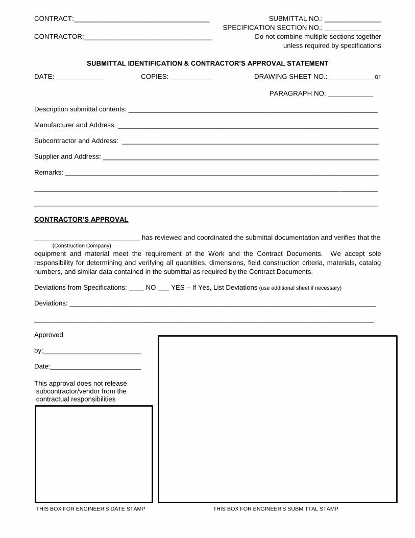
CONTRACT:____________________________________ SUBMITTAL NO.: _______________
SPECIFICATION SECTION NO.: _______________
CONTRACTOR:__________________________________ Do not combine multiple sections together
unless required by specifications
SUBMITTAL IDENTIFICATION & CONTRACTOR’S APPROVAL STATEMENT
DATE: _____________ COPIES: ___________ DRAWING SHEET NO.:____________ or
PARAGRAPH NO: ____________
Description submittal contents: __________________________________________________________________
Manufacturer and Address: _____________________________________________________________________
Subcontractor and Address: ____________________________________________________________________
Supplier and Address: _________________________________________________________________________
Remarks: ___________________________________________________________________________________
___________________________________________________________________________________________
___________________________________________________________________________________________
CONTRACTOR’S APPROVAL
____________________________ has reviewed and coordinated the submittal documentation and verifies that the (Construction Company)
equipment and material meet the requirement of the Work and the Contract Documents. We accept sole
responsibility for determining and verifying all quantities, dimensions, field construction criteria, materials, catalog
numbers, and similar data contained in the submittal as required by the Contract Documents.
Deviations from Specifications: ____ NO ___ YES – If Yes, List Deviations (use additional sheet if necessary)
Deviations: _________________________________________________________________________________
__________________________________________________________________________________________
Approved
by:__________________________
Date:________________________
This approval does not release subcontractor/vendor from the contractual responsibilities
THIS BOX FOR ENGINEER'S DATE STAMP THIS BOX FOR ENGINEER'S SUBMITTAL STAMP

THIS PAGE LEFT BLANK

Frankfort Public Service District Water Improvement Project FWAT-16-06 Wiley Ford, West Virginia Water Storage Tank – Contract 6
Rummel, Klepper & Kahl, LLP Consulting Engineers
01500 - 1
SECTION 01500
TEMPORARY FACILITIES
PART 1 - GENERAL
1.01 SUMMARY
A. Section Includes:
1. This Section specifies requirements for temporary services and facilities, including utilities, construction and support facilities, security, and protection for this Project.
2. Temporary construction and support facilities: Including installation, maintenance and removal are to be handled by the Contractor.
1.02 RESPONSIBILITIES
A. Contractor shall provide the following temporary construction, utilities, facilities, and controls for the use by the Engineer.
1. Sanitary facilities including drinking water
2. Rodent and pest control.
3. Environmental Protection.
4. Project Identification Sign.
B. Contractor shall be responsible for the implementation of safety programs and initiatives. These documents do not intend to define any Contractor’s responsibility to safety. It is expected that the Contractor will perform their activities in a safe manner and in accordance to industry regulations including those imposed by OSHA. Similarly, these Specifications shall not be construed as defining security measures.
1.03 SUBMITTALS
A. Temporary Utilities: Submit reports of tests, inspections, meter readings and similar procedures performed on temporary utilities.
B. Implementation and Termination Schedule: Submit a schedule indicating implementation and termination of each temporary utility within 15 days of the date established for commencement of the work.
1.04 QUALITY ASSURANCE
A. Regulations: Comply with industry standards and applicable laws and regulations of authorities having jurisdiction, including but not limited to:
1. Building code requirements.
Frankfort Public Service District Water Improvement Project FWAT-16-06 Wiley Ford, West Virginia Water Storage Tank – Contract 6
Rummel, Klepper & Kahl, LLP Consulting Engineers
01500 - 2
2. Health and safety regulations.
3. Utility company regulations.
4. Police, fire department and rescue squad rules.
5. Environmental protection requirements.
B. If the Contract Documents, laws, ordinances, rules, regulations or orders of any public authority having jurisdiction require any Work to be inspected, tested or approved, the Contractor shall give the Engineer timely notice of its readiness and of the date arranged, so the Engineer may observe such inspection, testing or approval. The Contractor shall bear all costs of such inspections, test and approvals unless otherwise provided.
C. If, after commencement of the Work, the Engineer determines that any work requires special testing, he will, upon written authorization from the Owner, instruct the Contractor to order such special testing. If such special testing reveals a failure of the work to comply (1) with the requirements of the Contract Documents, or (2) with respect to the performance of the work with laws, ordinances, rules, regulations or orders of any public authority having jurisdiction, the Contractor shall bear all costs thereof, including Engineer’s additional services made necessary by such failure; otherwise, the Owner shall bear such costs, and an appropriate supplement shall be issued.
D. Required certificates of inspection, testing or approval shall be secured by the Contractor and promptly delivered by him to the Engineer.
E. Neither the observations of the Engineer nor inspections, tests or approvals by persons other than the Contractor shall relieve the Contractor from his obligations to perform the work in accordance with the Contract Documents.
1.05 PROJECT CONDITIONS
A. Temporary Utilities: Prepare a schedule indicating dates for implementation and termination of each temporary utility. At the earliest feasible time, when acceptable to the Owner, change over from use of temporary service to use of the permanent service.
B. Conditions of Use: Keep temporary services and facilities clean and neat in appearance. Operate in a safe and efficient manner. Take necessary fire prevention measures. Do not overload facilities or permit them to interfere with progress. Do not allow hazardous, dangerous or unsanitary conditions, or public nuisances to develop or persist on the site.
PART 2 - PRODUCTS
2.01 ROADWAYS
A. Existing Roadways: The Contractor shall maintain and clean, regularly, roadways, drives and parking areas within the site. Any damage caused by the use of these areas for construction purposes shall be repaired by the Contractor at his expense.

Frankfort Public Service District Water Improvement Project FWAT-16-06 Wiley Ford, West Virginia Water Storage Tank – Contract 6
Rummel, Klepper & Kahl, LLP Consulting Engineers
01500 - 3
B. Temporary Roadways: The Contractor shall construct and maintain roadways and parking areas within the site, as required, in order to provide proper access to building or structure(s). The roadways and parking areas shall be constructed in accordance with base course specified and shall be kept in a usable condition throughout the period of construction. Location(s) shall be coordinated with the Owner.
2.02 FIELD OFFICE
Not Applicable
2.03 TEMPORARY TELEPHONE
Not Applicable
2.04 SANITARY PROVISIONS
Contractor shall provide and maintain, in a neat and sanitary condition, suitable toilet accommodations for the use of persons on the Project, complying with the requirements or regulations of the governing body having jurisdiction thereof.
2.05 TEMPORARY UTILITIES AND FACILITIES
A. Use of electric service shall be arranged and maintained by Contractor.
B. The Contractor shall provide extension cords and hoses for extending the existing services as required for his own use.
2.06 TEMPORARY WATER SUPPLY
A. The Contractor shall, at his own cost and expense, provide, protect and maintain an adequate non-potable water supply, for construction use on the Project during the period of construction, either by means of the permanent water supply line or by the installation of a temporary water supply.
B. If there is a charge for water, said charge shall be paid by the Contractor.
2.07 TEMPORARY ELECTRICAL LIGHT AND POWER
A. The Contractor shall, at his own cost and expense, install, operate, protect, have inspected and maintain a temporary electric service for construction light and power.
B. The service to be provided, unless otherwise specifically provided, shall be a minimum 200 Amp service, single phase, three wire, 120/240 volts with fused safety switch protection and the necessary disturbing facilities and meter, if required.
1. Provide electric service required for building heat during dry-in.
2. All 120-volt, single phase, 15 Amp and 20 Amp receptacle outlets shall have ground fault circuit interrupter protection.
Frankfort Public Service District Water Improvement Project FWAT-16-06 Wiley Ford, West Virginia Water Storage Tank – Contract 6
Rummel, Klepper & Kahl, LLP Consulting Engineers
01500 - 4
C. The Contractor, at all times, shall provide and pay for all maintenance, servicing, operation and supervision of the service and distributing facilities necessary for maintaining temporary heat and ventilation, after same is required in the building.
2.08 TEMPORARY HEAT AND VENTILATION
Not Applicable
2.09 ADDITIONAL VENTILATION IN OCCUPIED AREAS
Not Applicable
2.10 PROJECT IDENTIFICATION SIGNS
A. The Contractor shall provide and maintain project identification signs. The signs shall be erected at a location of high public visibility as directed by the Engineer. The Contractor shall obtain all necessary permits at no additional cost.
B. Project identification sign shall be approved by Engineer for construction, graphic design, colors, and lettering and shall include:
1. Title of Project
2. Name of Owner
3. Engineer
4. Contractors
C. Restriction of Signs: No advertising signs may be installed anywhere on the site. The Contractor’s name and other information will be placed on the job sign.
D. Remove signs upon completion of construction.
E. The Contractor shall provide sign(s) as specified in the Contract Manual and as required by funding agency.
PART 3 - EXECUTION
3.01 INSTALLATION
A. Use qualified personnel for installation of temporary facilities. Locate facilities where they shall serve the Project adequately and result in minimum interference with performance of the Work. Relocate and modify facilities as required when requested by the Engineer.
B. Provide each facility ready for use when needed to avoid delay. Maintain and modify as required. Do not remove until facilities are no longer needed or are replaced by authorized use of completed permanent facilities.
3.02 TEMPORARY UTILITIES
The Contractor shall furnish and install all equipment, wiring, accessories, etc. to maintain all temporary electric, telephone, gas, water and sewer utilities required for general construction, start-up, and initial operation of the plant improvements including those temporary utilities required for temporary offices of the Owner and Engineer and

Frankfort Public Service District Water Improvement Project FWAT-16-06 Wiley Ford, West Virginia Water Storage Tank – Contract 6
Rummel, Klepper & Kahl, LLP Consulting Engineers
01500 - 5
temporary facilities to keep the existing treatment plant in operation. Temporary utilities shall be provided throughout the construction period until Substantial Completion of the entire project. All costs for providing temporary utilities required for the general construction shall be paid by the Contractor and included in the Contract Price. The Owner will pay all utility costs associated with keeping the existing treatment plant facilities in operation during the construction period.
3.03 TEMPORARY UTILITY INSTALLATION
A. General: Engage the appropriate local utility company to install temporary service or connect to existing service. Where the company provides only part of the service, provide the remainder with matching, compatible materials and equipment; comply with the company’s recommendations.
1. Arrange with the company and existing users for a time when service can be interrupted, where necessary, to make connections for temporary services.
2. Provide adequate capacity at each stage of construction. Prior to temporary utility availability, provide trucked-in services.
3. Obtain easements to bring temporary utilities to the site, where the Owner’s easements cannot be used for that purpose.
4. Use Charges: Costs or use charges for temporary facilities are not chargeable to the Owner or Engineer, and will not be accepted as a basis of claims for a Change Order.
B. Water Service: Install water service and distribution piping of sizes and pressures adequate for construction until permanent water service is in use. Installation, maintenance and removal are by the Contractor.
1. Disinfection: Disinfect temporary water piping prior to use.
C. Temporary Electric Power Service: Provide waterproof, grounded electric power service and distribution system of sufficient size, capacity, and power characteristics during construction period. Include meters, transformers, overload protected disconnects, automatic ground fault interrupters and main distribution switch gear. Installation, maintenance and removal, including any fees, are by the Contractor. The Contractor shall be responsible for the monthly usage costs.
D. Temporary Lighting: Wherever overhead floor or roof deck has been installed, provide temporary lighting with local switching. Installation, maintenance and removal are by the Contractor.
1. Install, maintain, and operate temporary lighting that shall fulfill security and protection requirements, without operating the entire system, and shall provide adequate illumination for construction operations and traffic conditions.
E. Sewers and Drainage: If sewers are available, provide temporary connections to remove effluent that can be discharged lawfully. If sewers are not available or cannot be used, provide drainage ditches, dry wells, stabilization ponds and similar facilities. If neither sewers nor drainage facilities can be lawfully used for
Frankfort Public Service District Water Improvement Project FWAT-16-06 Wiley Ford, West Virginia Water Storage Tank – Contract 6
Rummel, Klepper & Kahl, LLP Consulting Engineers
01500 - 6
discharge of effluent, provide containers to remove and dispose of effluent off the site in a lawful manner. Installation, maintenance and removal are by the Contractor, including any installation fees.
1. Filter out excessive amounts of soil, construction debris, chemicals, oils and similar contaminants that might clog sewers or pollute waterways before discharge.
2. Connect temporary sewers to the municipal system as directed by the sewer department officials.
3. Maintain temporary sewers and drainage facilities in a clean, sanitary condition. Following heavy use, restore normal conditions promptly.
F. Provide earthen embankments and similar barriers in and around excavations and subgrade construction, sufficient to prevent flooding by runoff of storm water from heavy rains.
3.04 TEMPORARY CONSTRUCTION AND SUPPORT FACILITIES INSTALLATION
A. Locate field offices, storage sheds, sanitary facilities, and other temporary construction and support facilities for easy access.
1. Maintain temporary construction and support facilities until near Substantial Completion. Remove prior to Substantial Completion. Personnel remaining after Substantial Completion will be permitted to use permanent facilities, under conditions acceptable to the Owner.
B. Provide incombustible construction for offices, shops and sheds located within the construction area or within 30 feet of building lines. Comply with requirements of NFPA 241.
C. Temporary Heat: Provide temporary heat required by construction activities, for curing or drying of completed installations or protection of installed construction from adverse effects of low temperatures or high humidity; select safe equipment that will not have a harmful effect on completed installations or elements being installed. Coordinate ventilation requirements to produce the ambient condition required and minimize consumption of energy.
D. Heating Facilities: Except where use of the permanent system is authorized, Contractor shall provide vented self-contained LP gas or fuel oil heaters with individual space thermostatic control. All heaters must be acceptable to the Fire Marshal.
1. Use of gasoline-burning space heaters, open flame, or salamander type heating units is prohibited.
E. Change, Storage and Fabrication Sheds: Install change, storage and fabrication sheds, sized, furnished and equipped to accommodate materials and equipment involved, including temporary utility service. Sheds may be open shelters or fully enclosed spaces within the building or elsewhere on the site.
F. Sanitary facilities include temporary toilets, wash facilities and drinking water fixtures. Comply with regulations and health codes for the type, number, location, operation and maintenance of fixtures and facilities. Install where
Frankfort Public Service District Water Improvement Project FWAT-16-06 Wiley Ford, West Virginia Water Storage Tank – Contract 6
Rummel, Klepper & Kahl, LLP Consulting Engineers
01500 - 7
facilities will best service the Project’s needs. Use of pit-type toilets will not be permitted.
1. Provide toilet tissue, paper towels, paper cups and similar disposable materials for each facility. Provide covered waste containers for used material.
G. Wash Facilities: Contractor shall install wash facilities supplied with potable water at convenient locations for personnel involved in handling materials that require wash-up for a healthy and sanitary condition. Dispose of drainage properly. Supply cleaning compounds appropriate for each condition, except asbestos removal.
1. Provide safety showers, eye-wash fountains and similar facilities for convenience, safety and sanitation of personnel.
H. Temporary Enclosures: Provide temporary enclosure for protection of construction and existing building from exposure to inclement weather.
1. Where heat is needed and the permanent building enclosure is not complete, provide temporary enclosures where there is no other provision for containment of heat. Coordinate enclosure with ventilating and material drying or curing requirements to avoid dangerous conditions and effects.
2. Install tarpaulins securely with incombustible wood framing and other materials.
3. Close openings through floor or roof decks and horizontal surfaces with load-bearing wood framed construction.
4. Where temporary wood or plywood enclosure exceeds 100 square feet in area, use UL-labeled fire retardant treated material for framing and main sheathing.
I. Temporary Lifts, Hoists, and Scaffolding: Contractor shall assume responsibility for hoisting materials and employees. Truck cranes and similar devices used for hoisting materials are considered “tools and equipment” and not temporary facilities. Coordinate placement and use.
J. Project Identification and Temporary Signs: Prepare temporary signs of the size required; install signs where indicated to inform the public and persons seeking entrance to the Project. Support on posts or framing of preservative treated wood. Do not permit installation of unauthorized signs.
1. Temporary Signs: Prepare signs to provide directional information to construction personnel and visitors.
K. Collection and Disposal of Waste: Collect waste from the site daily. Comply with requirements of NFPA 241 for removal of combustible waste material and debris. Enforce requirements strictly. Do not hold materials more than 7 days during normal weather or 3 days when the temperature is expected to rise above 80oF (27oC). Handle hazardous, dangerous, or unsanitary waste materials separately from other waste by containerizing properly. Dispose of material in a lawful manner. Dumpster shall be placed in locations directed by the Engineer.

Frankfort Public Service District Water Improvement Project FWAT-16-06 Wiley Ford, West Virginia Water Storage Tank – Contract 6
Rummel, Klepper & Kahl, LLP Consulting Engineers
01500 - 8
3.05 PARKING AND TRAILER LOCATION
A. All construction traffic, including employee traffic, trucking, and delivery of materials and equipment, shall be controlled by the Contractor and shall enter the site only by routes prescribed by the Contractor. Access to the site by other routes will be prohibited.
B. The Contractor shall take all precautions to prevent tracking of mud and debris onto the highways and streets.
3.06 SECURITY AND PROTECTION FACILITIES INSTALLATION
A. Except for use of permanent fire protection as soon as available, do not change over from use of temporary security and protection facilities to permanent facilities until Substantial Completion.
B. Temporary Fire Protection: Until fire protection needs are supplied by permanent facilities, install and maintain temporary fire protection facilities of the types needed to protect against predictable and controllable fire losses.
1. Locate fire extinguishers where convenient and effective for their intended purpose.
2. Store combustible materials in fire-safe locations.
3. Maintain unobstructed access to fire extinguishers, fire hydrants, temporary fire protection facilities, stairways and other access routes for fighting fires. Prohibit smoking in hazardous fire exposure areas.
4. Provide supervision of welding operations, combustion type temporary heating units, and similar sources of fire ignition.
C. Permanent Fire Protection: At the earliest feasible date in each area of the Project, complete installation of the permanent fire protection facility, including connected services, and place into operation and use. Instruct key personnel on use of facilities.
D. Barricades, Warning Signs and Lights: Comply with standards and code requirements for erection of structurally adequate barricades. Paint with appropriate colors, graphics and warning signs to inform personnel and the public of the hazard being protected against. Where appropriate and needed, provide lighting, including flashing red or amber lights.
E. Security Enclosure and Lockup: Contractor shall provide protection against vandalism, theft and similar violations of security; Owner shall not be responsible for costs associated with these occurrences.
F. Environmental Protection: Provide protection, operate temporary facilities and conduct construction in ways and by means that comply with environmental regulations, and minimize the possibility that air, waterways and subsoil might be contaminated or polluted, or that other undesirable effects might result. Avoid use of tools and equipment which product harmful noise. Restrict use of noise making tools and equipment to hours that will minimize complaints.

Frankfort Public Service District Water Improvement Project FWAT-16-06 Wiley Ford, West Virginia Water Storage Tank – Contract 6
Rummel, Klepper & Kahl, LLP Consulting Engineers
01500 - 9
3.07 OPERATION, TERMINATION AND REMOVAL
A. Supervision: Enforce strict discipline in use of temporary facilities. Limit availability of temporary facilities to essential and intended uses to minimize waste and abuse.
B. Maintenance: Maintain facilities in good operating condition until removal. Protect from damage by freezing temperatures and similar elements.
1. Maintain operation of temporary enclosures, heating, cooling, humidity control, ventilation and similar facilities on a 24-hour day basis where required to achieve indicated results and to avoid possibility of damage.
2. Protection: Prevent water filled piping from freezing. Maintain markers for underground lines. Protect from damage during excavation operations.
C. Termination and Removal: Unless the Contractor or Engineer requires that it be maintained longer, remove each temporary facility when the need has ended, or when replaced by authorized use of a permanent facility, or no later than Substantial Completion. Complete or, if necessary, restore permanent construction that may have been delayed because of interference with the temporary facility. Repair damaged work, clean exposed surfaces and replace construction that cannot be satisfactorily repaired.
1. Materials and facilities that constitute temporary facilities are property of the party furnishing the facility
2. At Substantial Completion, clean and renovate permanent facilities that have been used during the construction period, including but not limited to:
a. Replace air filters, and clean inside of ductwork and housings.
b. Replace lamps that are burned out or noticeably dimmed by substantial hours of use.
END OF SECTION
Frankfort Public Service District Water Improvement Project FWAT-16-06 Wiley Ford, West Virginia Water Storage Tank – Contract 6
Rummel, Klepper & Kahl, LLP Consulting Engineers
01500 - 10
THIS PAGE LEFT BLANK
Frankfort Public Service District Water Improvement Project FWAT-16-06 Wiley Ford, West Virginia Water Storage Tank – Contract 6
Rummel, Klepper & Kahl, LLP Consulting Engineers
01600 - 1
SECTION 01600
MATERIAL AND EQUIPMENT
PART 1 - GENERAL
1.01 SUMMARY
A. Section Includes
1. Products
2. Substitutions
3. Transportation and Handling
4. Storage and Protection
5. Testing of Equipment
6. Product Contamination
B. Related Requirements
1. General Conditions
2. Section 01010 - General Requirements
3. Section 01700 - Project Closeout
1.02 PRODUCTS (STANDARDS OF QUALITY)
A. Products include material, equipment, and systems.
B. Comply with Specifications and referenced standards as minimum requirements.
C. The materials, articles, devices, products, fixtures, form or type of construction in these Specifications are specified by trade name, manufacturer’s name, catalog reference or by description, to establish the standard and quality and design desired, and shall not be interpreted as limiting competition.
D. Design, arrangement, details, utility requirements and dimensions shown on Drawings and included in Schedules and Specifications have been determined and established, after considerable study and planning, based on the criteria of the first named manufacturer. Other manufacturers named or substitutes are considered to be able to perform the same function but not necessarily have same design, arrangement, details, utility requirements and dimensions. Therefore, if a Contractor desires to use a manufacturer or product other than first named, he shall assume the responsibility of coordination and all costs or extra charges, including costs in connection with Work of other trades or separate Contracts, necessitated by their use.

Frankfort Public Service District Water Improvement Project FWAT-16-06 Wiley Ford, West Virginia Water Storage Tank – Contract 6
Rummel, Klepper & Kahl, LLP Consulting Engineers
01600 - 2
E. Colors: Where indicated or specified as “color to be selected” or “color selected by the Engineer” the color will be selected from the full range of standard colors of the first named manufacturer or an equivalent color of other manufacturers.
1.03 SOURCE OF SUPPLY AND QUALITY OF MATERIALS
A. The source of supply of each of the materials must be approved in writing by the Engineer before delivery is started. Representative preliminary samples of the character and quantity prescribed shall be submitted by the Contractor, said samples being taken under the observation of the Engineer, for examination, and tested in accordance with the methods referred to herein. Only materials conforming to the requirements of these specifications and approved by the Engineer shall be used in the work. No materials, which, after approval, have in any way become unfit for use, shall be used. The Contractor shall notify the Engineer where and when he purchases fabricated or manufactured materials for the Contract, and such notice shall be given the Engineer in sufficient time to allow for inspection of such materials at the point of manufacture.
B. Unless a material has a satisfactory record of performance, the Engineer reserves the right to withhold approval of a new source of supply, even though it meets the specification requirements, until its qualities have been verified and proved in actual service.
C. Tests of all materials specified will be made in accordance with the latest official approved methods, effective as of the date of Contract, described in the Contract Documents. Where ASTM, AASHTO, ANSI, AWWA, or similar standards of national repute are stipulated, the reference shall be construed to be the latest effective specification.
D. The Contract drawings, specifications, and/or supplemental specifications indicate the name of manufacturer, trade name, model number or type of equipment or materials to be used as a standard for the Bidder's proposal. All bids shall be based on the equipment and materials specified. Reference to model number or catalog number is not intended to supersede the basic duty and performance requirements specified or indicated on the drawings. References made to a particular product or model of the manufacturer are made to identify a particular design quality, construction, arrangement or style.
E. The low Bidder shall submit, within ten (10) working days after opening of bids, a complete statement of the origin, composition and manufacture including manufacturer's name and catalog numbers of all materials and equipment to be used in the work to be performed under this contract. Submission and/or approval of this list of materials and equipment shall not, however, relieve the Contractor of submitting detailed working drawings on all equipment for approval nor shall it constitute prior approval of any specific item of equipment before the final detailed working drawings are submitted.
F. Failure of the Contractor to submit the list of materials within the ten (10) working day period shall forfeit the Contractor's right to make any change or substitution from the exact equipment specified and the Engineer shall have the right to select the material and equipment to be furnished.
G. Where a Contractor proposes to use a substitute item, the installation of which will require any redesign of the structure, partitions, foundations, piping, ductwork, wiring, controls, or of any other part of the project, all such redesign,

Frankfort Public Service District Water Improvement Project FWAT-16-06 Wiley Ford, West Virginia Water Storage Tank – Contract 6
Rummel, Klepper & Kahl, LLP Consulting Engineers
01600 - 3
and all new drawings and detailing required therefore shall be prepared by a Registered Professional Engineer licensed to practice in Maryland for the Contractor at the Contractor's expense for the approval of the Engineer. Where the substitution of any item or items requires a different quantity and arrangement of ductwork, piping, wiring, conduit, and equipment from that specified or indicated on the contract drawings, the Contractor shall include the total cost of such changes in his bid. Later requests for additional compensation for substitutes will not be considered. All equipment and materials named shall be furnished in full accordance with the contract drawings and specifications.
H. If the Contractor proposes to substitute materials or equipment as "equal" to those specified, it shall be the Contractor's responsibility to furnish complete, specific, detailed information from the manufacturer or supplier of the materials or equipment he proposes to furnish, in which the requirements of the contract specifications are shown to be met. This shall consist of a point-by-point comparison of the contract specification requirements with the material or equipment proposed to be furnished. In the event the contract specifications mention a model number and manufacturer in lieu of a detailed description and manufacturer, a point-by-point comparison of the equipment specified under the contract and that proposed to be substituted shall be furnished by the Contractor. The burden of responsibility in furnishing this information is with the Contractor. If incomplete or irrelevant data is submitted as evidence of compliance with this section of the specifications, the data will be returned to the Contractor and the request for approval will be denied.
I. All materials and equipment required for the work shall be new, of first-class quality, and shall be furnished, delivered, erected, connected, and finished in every detail, and shall be so erected and arranged as to fit properly into the building spaces. Where no specific kind of quality or material is given, a first-class standard article approved by the Engineer shall be furnished.
J. In cases where material, a device, or part of the equipment is referred to in the singular number, it is intended that such reference shall apply to as many items of materials, devices, or parts of the equipment as are required to complete the installation.
K. The Contractor shall submit written evidence from each equipment manufacturer showing the availability of factory authorized servicemen within a distance of 200 miles from the project site for all equipment to be provided.
L. When a material has been approved, no change in brand or make will be permitted unless:
1. The manufacturer cannot make satisfactory delivery; or
2. The material delivered fails to comply with the Contract requirements.
1.04 DEFECTIVE MATERIALS
All materials not conforming to the requirements of these Specifications will be deemed defective, and all such materials, whether in place or not, shall be removed immediately from the site of the work, unless otherwise permitted by the Engineer. No rejected material, the defects of which having been subsequently corrected, shall be used until approval has been given. Should the Contractor fail to comply with any order of the Engineer made under the provisions of this article, the Engineer shall have the authority
Frankfort Public Service District Water Improvement Project FWAT-16-06 Wiley Ford, West Virginia Water Storage Tank – Contract 6
Rummel, Klepper & Kahl, LLP Consulting Engineers
01600 - 4
to remove and replace defective materials, and to deduct the cost of removal and replacement from any monies due or to become due the Contractor.
1.05 ADDITIONAL COSTS RESULTING FROM SUBSTITUTE MATERIAL OR EQUIPMENT
The Contractor shall comply with General Conditions regarding substitute material or equipment. Additional costs resulting from installation of approved substitute material or equipment including alterations in connecting piping or conduit, changes or alteration to foundations, anchor bolts, control systems, or other additional costs attributed to use of the substitute material or equipment shall be the sole responsibility of the Contractor.
1.06 TRANSPORTATION AND HANDLING
A. Transport products by methods to avoid product damage; deliver in undamaged condition in manufacturer’s unopened containers or packaging, dry.
B. Provide equipment and personnel to handle products by methods to prevent soiling or damage.
C. Promptly inspect shipments to assure that products comply with requirements, quantities are correct, and products are undamaged.
1.07 CONTRACTOR STORAGE AREA
A. The Contractor's storage area, for the placing of equipment, materials, inspector's and contractor's offices, and any additional space required for storage, shall be located by the Contractor at his expense.
B. The Contractor shall adhere to all state and local laws and regulations concerning environmental pollution control and abatement.
1.08 STORAGE AND PROTECTION
A. Store products in accordance with manufacturer’s instructions, with seals and labels intact and legible. Store sensitive products in weather-tight enclosures; maintain within temperature and humidity ranges required by manufacturer’s instructions.
B. For exterior storage of fabricated products, place on sloped supports aboveground. Cover products subject to deterioration with impervious sheet covering; provide ventilation to avoid condensation.
C. Store loose granular materials on solid surfaces in a well-drained area; prevent mixing with foreign matter.
D. Arrange storage to provide access for inspection. Periodically inspect to assure products are undamaged and are maintained under required conditions.
1.09 EQUIPMENT STORAGE
A. The Contractor is required to provide a covered storage area for equipment delivered to the site. Electrical and instrumentation equipment shall be stored in a closed, conditioned storage area. All equipment delivered and stored on the
Frankfort Public Service District Water Improvement Project FWAT-16-06 Wiley Ford, West Virginia Water Storage Tank – Contract 6
Rummel, Klepper & Kahl, LLP Consulting Engineers
01600 - 5
project site shall be in strict accordance with the equipment supplier’s storage procedures.
B. The Contractor shall submit along with the shop drawing submittal for each piece of equipment the equipment manufacturer’s recommended short term and long term storage maintenance procedures. These procedures are to be implemented fully by the Contractor. Using the information submitted by the manufacturer, the Contractor shall prepare and submit for approval a schedule listing maintenance tasks and schedule dates for each task for each piece of equipment. The Owner’s Representative will verify that the recommended procedures are being performed, and he along with the Contractor’s representative will initial a log sheet when the maintenance task is completed. These storage maintenance procedures shall be performed from the time the equipment arrives on site until the equipment is placed into operation.
C. Motors with condensate heaters delivered to the site which are not installed within 30 days or motors installed but not operational within 30 days shall be wired to provide full operation use of the condensate heaters.
D. Lubricant drain piping, valves, end plugs and associated components required for servicing equipment including lubricants for storage, start-up and normal operation and desiccant bags for moisture protection of motors, actuators, and panels shall be furnished by the Contractor.
1.10 TESTING OF EQUIPMENT
A. After permanent heating, plumbing or electrical system and equipment have been installed, it shall be the responsibility of the Contractor installing such system and equipment to operate it for a satisfactory period of time as required by Engineer for proper testing and instruction of operating personnel.
B. Fuel, electricity and water, required for proper testing of permanent equipment and for the period of instructing personnel, shall be supplied by the Contractor performing the test or instruction.
1.11 START-UP AND PERFORMANCE TESTING
A. All utilities, supplies and materials required in connection with start-up and performance testing shall be provided and paid for by the Contractor. Laboratory testing services will be performed by a testing laboratory engaged and paid for by the Contractor and approved by the Engineer.
B. Potable water is available from the Owner’s existing potable water distribution system. The cost associated with providing the potable water connection and the potable water including the cost for metered service throughout the construction period to Substantial Completion of the entire project shall be paid by the Contractor and included in the Contract Price bid.
C. The Contractor is responsible to fill tanks, sumps, and pits with clean water as required to fulfill performance testing requirements for pumps, aerators, mixers, blowers, etc.
Frankfort Public Service District Water Improvement Project FWAT-16-06 Wiley Ford, West Virginia Water Storage Tank – Contract 6
Rummel, Klepper & Kahl, LLP Consulting Engineers
01600 - 6
1.12 VIBRATION AND INFRARED TESTING
A. Vibration and infrared testing shall be performed by an independent testing agency engaged and paid for by the Contractor and approved by the Engineer. The Contractor will be responsible for the vibration testing and infrared testing for that equipment provided under this Contract. All costs for the initial testing and re-testing (if required) shall be included in the lump sum price for this Contract. Acceptable testing limits will be the limits submitted as part of the shop drawing submittal by the equipment suppliers. Testing limits which are submitted and do not meet the minimum standard of the industry for that piece of equipment will not be accepted, and the standard of the industry will be used as the allowable limit for testing. The Contractor providing the equipment shall assume all costs in the event that the equipment fails to meet the requirements of the test. These costs include costs for additional vibration testing, additional infrared analysis, additional utilities, etc., for test reruns when such test reruns were caused by faults properly the responsibility of the Contractor. The Contractor will provide the Owner with all test data in report form. If equipment fails the vibration or infrared analysis, the Contractor will, within three weeks from the initial test date, perform the required corrective measures and/or provide evidence of substantial effort to bring the equipment within acceptable testing limits.
B. All vibration and infrared testing will be performed in the field at the job site. Items for vibration testing should include all drive motors and drive shafts. Tests should be done when the equipment is installed and operating under load. Test points should include all support points and shaft axial end points.
C. Perform vibration testing for the following equipment:
(Confirm that Factory vibration testing was performed on pumps greater than 2HP)
1. Pumps greater than 2 HP
2. Aerators
3. Mixers
4. Emergency Generator
D. Perform an infrared scan test on all electrical connections to control panels, junction boxes, motors, and electrical components furnished under this Contract. Furnish a thermograph (infrared photo) to the Engineer of all problems areas with the temperature rise and location noted.
1.13 PRODUCT CONTAMINATION
A. All products provided for this Project shall be completely free of asbestos and polychlorinated biphenyl (PCB).
B. Potable water systems and products accessible to public such as paint coatings shall be lead free.
C. Materials and adhesives shall be formaldehyde free.

Frankfort Public Service District Water Improvement Project FWAT-16-06 Wiley Ford, West Virginia Water Storage Tank – Contract 6
Rummel, Klepper & Kahl, LLP Consulting Engineers
01600 - 7
D. The Contractor shall submit a certificate on company letterhead singed by the Project Superintendent and a Vice President indicating that materials provided for the Project are not contaminated by asbestos, polychlorinated biphenyl (PCB), lead or formaldehyde.
E. When required by specification sections, submit 6 copies of a “Certificate of Non-Contamination”. Certificate shall be prepared on the manufacturer’s letterhead, signed by a Vice President, and indicate that materials provided for the Project are not contaminated by asbestos.
F. Material Safety Certifications: The Contractor shall submit 6 copies of a letter from the manufacturer of each product used on this Project, stating that, at the time of its use and installation in the Project, the product posed no known health hazard to the occupant of the building as a result of exposure to the product.
PART 2 - PRODUCTS
NOT USED
PART 3 - EXECUTION
NOT USED.
END OF SECTION

Frankfort Public Service District Water Improvement Project FWAT-16-06 Wiley Ford, West Virginia Water Storage Tank – Contract 6
Rummel, Klepper & Kahl, LLP Consulting Engineers
01600 - 8
THIS PAGE LEFT BLANK

Frankfort Public Service District Water Improvement Project FWAT-16-06 Wiley Ford, West Virginia Water Storage Tank – Contract 6
Rummel, Klepper & Kahl, LLP Consulting Engineers
01700 - 1
SECTION 01700
PROJECT CLOSEOUT
PART 1 - GENERAL
1.01 SUMMARY
A. This Section specifies administrative and procedural requirements for project closeout, including but not limited to:
1. Inspection procedures.
2. Project record document submittals. (As-built Drawings)
3. Operating and maintenance manual submittal
4. Release of liens.
5. Submittal of warranties.
6. Final cleaning.
7. Letter of Acceptance from Division of Highways, if applicable.
8. Consent of Surety for final payments.
9. Release from West Virginia Department of Tax and Revenue.
10. Statement from Engineer that work has been inspected and completed in accordance with approved contract documents.
11. Final adjusting Change Order.
1.02 REQUIREMENTS OF REGULATORY AGENCIES
Conduct cleaning and disposal operation to comply with codes, ordinances, regulation, and anti-pollution laws.
1.03 SUBSTANTIAL COMPLETION
A. Preliminary Procedures: Before requesting inspection for certification of Substantial Completion, complete the following. List exceptions in the request.
1. In the Application for Payment that coincides with, or first follows, the date Substantial Completion is claimed, show 100 percent completion for the portion of the work claimed as substantially complete. Include supporting documents for completion as indicated in these Contract Documents and a statement showing an accounting of changes to the Contract Sum.
2. If 100 percent completion cannot be shown, include a list of incomplete items, the value of incomplete construction, and reasons the Work is not complete.
3. Advise the Owner of pending insurance change-over requirements.

Frankfort Public Service District Water Improvement Project FWAT-16-06 Wiley Ford, West Virginia Water Storage Tank – Contract 6
Rummel, Klepper & Kahl, LLP Consulting Engineers
01700 - 2
4. Submit to the Engineer specific warranties, workmanship bonds, maintenance agreements, final certifications and similar documents.
5. Obtain and submit releases enabling the Owner unrestricted use of the work and access to services and utilities; include occupancy permits, operating certificates and similar releases.
6. Submit to the Engineer record drawings, maintenance manuals, and similar final record information.
7. Deliver spare parts, extra stock, and similar items to the Owner via the Engineer.
8. Complete start-up testing of systems, and instruction of the Owner’s operating and maintenance personnel. Discontinue or change-over and remove temporary facilities from the site, along with construction tools, mock-ups, and similar elements.
9. Complete final clean up requirements, including touch-up painting. Touch-up and otherwise repair and restore marred exposed finishes.
1.04 FINAL ACCEPTANCE
A. Preliminary Procedures: Before requesting final inspection for certification of final acceptance and final payment, complete the following. List exceptions in the request.
1. Submit the final payment request with releases and supporting documentation not previously submitted and accepted. Include certificates of insurance for products and completed operations where required.
2. Submit an updated final statement, accounting for final additional changes to the Contract Sum.
3. Submit a certified copy of the Engineer’s final inspection list of items to be completed or corrected, stating that each item has been completed or otherwise resolved for acceptance, and the list has been endorsed and dated by the Engineer.
4. Submit consent of surety to final payment.
B. Re-inspection Procedure: The Engineer will re-inspect the work upon receipt of notice that the work, including inspection list items from earlier inspections, has been completed, except items whose completion has been delayed because of circumstances acceptable to the Engineer.
1.05 RECORD DRAWINGS
A. The Contractor is required to keep an up-to-date set of Record Drawings (As-Constructed Drawings) for the project. In addition, the Contractor shall identify the location of all new piping installed, existing piping to remain and existing piping to be abandoned as it is installed or uncovered during the construction period. No trenching for piping shall be backfilled until the piping has been located by the Contractor. The Contractor shall also identify the location of all

Frankfort Public Service District Water Improvement Project FWAT-16-06 Wiley Ford, West Virginia Water Storage Tank – Contract 6
Rummel, Klepper & Kahl, LLP Consulting Engineers
01700 - 3
buried or embedded conduits and duct banks including new work and existing to remain or to be abandoned as it is installed or uncovered during the construction. Up-to-date is defined as containing modifications for work performed within the past 30 days. The record drawing information shall include but not be limited to the following:
1. All dimensional changes. Degree of dimensioning shall equal that of the original drawing except for the yard piping and site electrical drawings. The Record Drawing dimensioning for the yard piping and site electrical (buried or embedded conduits and duct banks) drawings shall include as a minimum both horizontal locational dimensioning from above grade permanent structure and elevation at each location where the process piping and electrical work enters or leaves a structure and at each change in direction. In addition, where the buried process piping and electrical work parallels the wall of a structure, horizontal dimension from the structure and elevation shall be provided at a minimum of two locations.
2. Electrical breaker designations for each circuit such as receptacles, lights, heaters, etc.
3. All internal piping valve and fitting modifications. Degree of detail shall be equal to that of the original drawing.
4. All structural reinforcement modifications.
5. All electrical conduit size and routing wire size and wiring quantity modifications, wiring number and tagging assignments.
6. All site work modifications such as roadways, sidewalks, grading, etc.
B. The Engineer will review the status of the Contractor’s record drawings on a monthly basis. If the record drawings do not meet the requirements stated above, 10% of the succeeding progress payments, in addition to the normal contract retaining, will be withheld until such time as the record drawings are brought into compliance.
C. The Contractor shall make the record drawings available to the Engineer whenever requested for reproduction by the Engineer so that he can begin preparation of the final record drawings to be supplied to the Owner.
D. At the end of the project, the Contractor’s record drawing set shall be turned over to the Engineer.
1.06 RECORD DOCUMENT SUBMITTALS
A. General: Do not use record documents for construction purposes; protect from deterioration and loss in a secure, fire-resistive location; provide access to record documents for the Engineer’s reference during normal working hours.
B. Record Drawings: A clean, undamaged set of blue or black line prints of Contract Drawings will be maintained by the Contractor. The Contractor shall mark the set to show the actual installation where the installation varies from the work as originally shown. Mark whichever drawing is most capable of showing conditions fully and accurately. Where Shop Drawings are used, record a cross-reference
Frankfort Public Service District Water Improvement Project FWAT-16-06 Wiley Ford, West Virginia Water Storage Tank – Contract 6
Rummel, Klepper & Kahl, LLP Consulting Engineers
01700 - 4
at the corresponding location on the Record Drawings. Give particular attention to concealed elements that would be difficult to measure and record at a later date.
1. Mark record sets with red erasable pencil; use other colors to distinguish between variations in separate categories of the work.
2. Mark new information that is important to the Owner but was not shown on Contract Drawings or Shop Drawings.
3. Note related Change Order numbers where applicable.
4. Organize Record Drawing sheets into manageable sets, bind with durable paper cover sheets, and print suitable titles, dates and other identification on the cover of each set. Upon completion of the work, submit Record Drawings to the Engineer for the Owner’s records.
C. Miscellaneous Record Submittals: Refer to other Specification Sections for requirements of miscellaneous record-keeping and submittals in connection with actual performance of the work. Immediately prior to the date or dates of Substantial Completion, complete miscellaneous records and place in good order, properly identified and bound or filed, ready for continued use and reference. Submit to the Engineer for the Owner’s records.
1.07 GUARANTEES, CERTIFICATES, OPERATION AND MAINTENANCE MANUALS
A. During the course of the work and within 6 weeks after approval of Shop Drawings, Contractor shall collect and assemble six (6) copies each of the guarantees, manufacturers’ specification sheets and/or working drawings, operation and maintenance instructions, parts list including exploded views, recommended safety procedures, and recommended list of spare parts. The Contractor shall submit all copies, with an itemized listing, to the Engineer.
B. Operation and Maintenance Manuals shall include all mechanical and electrical equipment specified herein including heating, ventilation, air conditioning and lighting equipment.
C. Operation and Maintenance Manuals shall include all electronically operated features of the building and all equipment specified in these Specifications.
D. The Operation and Maintenance Manuals shall be assigned a value of 10% of the equipment cost, and this assigned amount will be retained from progress payments until the manuals are submitted to and approved by the Engineer and the equipment is delivered to the site.
E. Furnish Operation and Maintenance Manuals on 8-1/2" x 11" sheets or booklets, loose bound in 3-ring binders with front and back page lifters, with binder contents indicated on the front and spine of the binder cover. All loose sheets shall be in vinyl page protectors with reinforced binding edge. Furnish drawings included in the manuals on 11" x 17" sheets laminated and folded to 8-1/2" x 11" or folded and placed in vinyl “envelope pockets” incorporated into the binder. All materials in manuals shall be original print quality manufacturer’s literature. Photo static copies of printed materials are not acceptable. Provide an index of the contents of each manual or a master index for a system consisting of several manuals. Provide printed and laminated, reinforced index tabs for each manual.
Frankfort Public Service District Water Improvement Project FWAT-16-06 Wiley Ford, West Virginia Water Storage Tank – Contract 6
Rummel, Klepper & Kahl, LLP Consulting Engineers
01700 - 5
Indexed sections to include Installation, Start-up, Operation, Troubleshooting, Maintenance, Parts List, Recommended Spare Parts and Miscellaneous Components. Submit no less than four (4) copies.
F. Include a detailed description of function of each principal component, procedures for starting, operation, overhaul and maintenance. Include safety precautions, test procedures and a catalog cross-reference to commercially available parts.
G. Submit a Preventive Maintenance and Lubrication Schedule for the equipment furnished which specifically explains the duties to be fulfilled by the Owner during the guarantee period. Manufacturer’s recommended lubricant plus two equal substitutes for all material, shall be included in the O&M Manuals.
1.08 RELEASE OF LIENS
A. The Contractor shall deliver to the Engineer a blanket release of liens covering all work performed under this Contract, including that of subcontractors, sub-subcontractors, vendors, and other suppliers of materials and labor. Execute the release of liens on documents similar to AIA Document G706, “Contractor’s Affidavit of Payment of Debtors and Claims”, and AIA Document G706A., “Contractor’s Affidavit of Release of Liens”.
B. The forms shall be executed by the authorized officer and notarized. All required attachments shall be included as noted on AIA Document G706. If exceptions are listed in either AIA Document G706 or Document G706A, the Contractor shall furnish bond satisfactory to the Owner for each exception.
1.09 PROJECT CLOSEOUT SUBMITTALS
A. Submit two copies of Project Closeout submittals bound in three-ring binders, clearly labeled to the type of submittal. Provide pocket folders for folded information.
B. Submittals shall be submitted within ten days of Substantial Completion and prior to final Application for Payment.
1. Exception: Operation and Maintenance Manuals shall be submitted within six weeks after approval of shop drawings or within ten days of Substantial Completion, whichever is earlier.
2. Refer to Sub-section 1.07.
C. Warranties and Bonds
1. Obtain warranties and bonds, executed in duplicate by responsible subcontractors, suppliers, and manufacturers.
2. Except for items put into use with the Owner’s permission, leave date of beginning of time of warranty until the date of Substantial Completion is determined.
3. Table of Contents: Neatly typed, in the sequence of the Table of Contents of the Project Manual; identify the number and title of the Specification Section in which product is specified.

Frankfort Public Service District Water Improvement Project FWAT-16-06 Wiley Ford, West Virginia Water Storage Tank – Contract 6
Rummel, Klepper & Kahl, LLP Consulting Engineers
01700 - 6
4. Separate each warranty or bond with index tab sheets keyed to Table of Contents. List subcontractor, supplier, and manufacturer, with name, address and telephone number of responsible principal.
PART 2 - PRODUCTS
2.01 CLEANING MATERIALS
A. Use only those materials which will not create hazards to health or property, and which will not damage finishes and surfaces.
B. Use only materials and methods recommended by manufacturer of material being cleaned.
PART 3 - EXECUTION
3.01 CLOSEOUT PROCEDURES
A. Operating and Maintenance Instructions: Each installer of equipment that requires regular maintenance shall arrange to meet with the Owner’s personnel to provide instruction in proper operation and maintenance. If installers are not experienced in procedures, provide instruction by manufacturer’s representatives. Include a detailed review of the following items.
1. Operation and maintenance manuals
2. Record documents
3. Spare parts and materials
4. Tools
5. Lubricants
6. Fuels
7. Identification systems
8. Control sequences
9. Hazards
10. Cleaning
11. Warranties and bonds
12. Maintenance agreements and similar continuing commitments.
B. As part of instruction for operating equipment, demonstrate the following procedures:
1. Start-up
2. Shutdown
3. Emergency operations
4. Noise and vibration adjustments
5. Safety procedures
Frankfort Public Service District Water Improvement Project FWAT-16-06 Wiley Ford, West Virginia Water Storage Tank – Contract 6
Rummel, Klepper & Kahl, LLP Consulting Engineers
01700 - 7
6. Economy and efficiency adjustments
7. Effective energy utilization
C. Training by factory representatives shall be videotaped by the Contractor in a VHS format, and the tapes then turned over to the Engineer upon completion of training.
3.02 INITIAL OPERATION
The Contractor shall place the completed Project, equipment and systems into initial operation. The schedule and sequence of the initial operation procedures shall be included in the Project Schedule. Coordinate the initial operation procedures with the Owner’s operating personnel.
3.03 FINAL CLEANING
A. All final cleaning shall be performed by the Contractor, unless otherwise specified.
B. Remove temporary protection and labels not required to remain.
C. Clean surfaces free of grease, mastic, adhesives, dust, dirt, stains, fingerprints, labels, and other foreign materials from sight-exposed interior and exterior surfaces, bringing them to a state or readiness for Owner occupancy.
D. Clean transparent glossy materials to a polished condition; remove foreign substances. Polish reflective surfaces to a clear shine.
E. Vacuum clean carpeted and similar soft surfaces as specified.
F. Clean, wash, and polish resilient and hard-surfaced floor as specified.
G. Clean surfaces of equipment; remove excess lubrication.
H. Clean plumbing fixtures, food service equipment, hospital equipment, and similar equipment to a sanitary condition.
I. Electrical Devices and Lighting:
1. Clean light fixtures, lamps and lenses.
2. Clean the faces of all electrical devices and cover plates for same, including power receptacles, switches, computer outlets, computer and TV outlets, TV outlets, telephones, communication speakers, fire alarm speakers, fire alarm pull stations, fire alarm flashing lights, smoke detectors, clocks, speaker volume control switches, security system motion detectors, and fire alarm horns.
3. Clean the fronts of all electrical panelboards and the main distribution switchboard.
J. Remove waste, foreign matter and debris from roofs, gutters, areaways and drainage systems.
Frankfort Public Service District Water Improvement Project FWAT-16-06 Wiley Ford, West Virginia Water Storage Tank – Contract 6
Rummel, Klepper & Kahl, LLP Consulting Engineers
01700 - 8
K. Remove waste, debris, and surplus materials from site. Clean grounds; remove stains, spills, and foreign substances from paved areas and sweep. Rake clean other exterior surfaces.
L. Clean permanent filters of ventilating equipment and replace disposable filters when units have been operated during construction; in addition, vacuum clean ducts, blowers and coils for every three months’ use; replace or clean strainers, dirt legs, etc.
3.04 TERMINAL INSPECTION
A. Two months prior to expiration of the one year guarantee period, the Contractor shall make an inspection of the work in the company of the Engineer and the Owner. The Engineer and the Owner shall be given no less than five days’ notice prior to the anticipated date of terminal inspection.
B. Where any portion of the work has proven to be defective and requires replacement, repair or adjustment, the Contractor shall immediately provide materials and labor necessary to remedy such defective work and shall execute such work without delay until completed to the satisfaction of the Engineer and the Owner, even though the date of completion of the corrective work may extend beyond the expiration date of the guarantee period.
C. The Contractor shall not be responsible for correction of work which has been damaged because of neglect or abuse by the Owner nor the replacement of parts necessitated by normal wear in use.
END OF SECTION

Frankfort Public Service District Water Improvement Project FWAT-16-06 Wiley Ford, West Virginia Water Storage Tank – Contract 6
Rummel, Klepper & Kahl, LLP Consulting Engineers
02040 - 1
SECTION 02040
AUDIO-VIDEO COLOR TAPING
PART 1 - GENERAL
1.01 SCOPE OF WORK
A. Furnish all labor, materials and equipment to furnish color audio video recording of the project site as specified herein.
B. Furnish to the Engineer an original and one copy of a continuous color audio video recording of the entire area within fifty (50) feet of the construction area. The recording shall be taken prior to any construction activity.
C. The Engineer reserves the right to reject the audio video recording because of poor quality, unintelligible audio or uncontrolled pan or zoom. Any recording rejected by the Engineer shall be rerecorded at no cost to the Owner. Under no circumstances shall construction begin until the Engineer has received and accepted the audio video DVD(s) by written acknowledgement.
D. The recording shall be performed by a qualified, established audio video recording firm knowledgeable in construction practices which has a minimum of one year of experience in the implementation of established inspection procedures.
E. The audio video recording firm shall submit three letters of recommendation from municipalities, and/or engineering firms indicating previous experience and ability to perform the work described in this contract. Data substantiating qualifications must be submitted and accepted prior to performing the survey.
PART 2 - PRODUCTS
(NOT USED)
PART 3 - EXECUTION
3.01 COLOR AUDIO VIDEO SURVEY
A. Furnish a continuous color audio-video recording of the entire area within fifty (50) feet of construction.
B. Complete coverage shall include all surface features within 50' of the work area to be utilized by Contractor and shall be supported by appropriate audio description made simultaneously with video coverage. Such coverage shall include, but not be limited to, all existing driveways, sidewalks, curbs, ditches, roadways, landscaping, trees, culverts, headwalls, and retaining walls, equipment, structures, pavements, manholes, vaults, handrails, etc. located within the aforementioned work zone. Video coverage shall extend to the maximum height of all structures within this zone.
C. All recording shall be done during times of good visibility. No recording shall be done during periods of visible precipitation, or when more than ten percent of the ground area is covered with standing water, unless otherwise authorized by Owner.
Frankfort Public Service District Water Improvement Project FWAT-16-06 Wiley Ford, West Virginia Water Storage Tank – Contract 6
Rummel, Klepper & Kahl, LLP Consulting Engineers
02040 - 2
D. Audio video over six (6) months old before start of construction shall be re-performed unless specifically waived in writing by Engineer.
3.02 AUDIO AND VIDEO
A. Contractor shall furnish continuous color, audio-video DVD(s) of professional quality.
B. Each DVD shall begin with the Owner's name, Contract name and number, Contractor's name, date and location information such as street name, direction of travel, viewing side, etc.
C. Information appearing on the DVD must be continuous and run simultaneously by computer generated transparent digital information. No editing or overlaying of information at a later date will be acceptable.
D. Digital information to appear in the upper left corner shall be as follows:
1. Name of Contractor
2. Day, date and time
3. Name of Project & Specification Number
E. Time must be accurate and continuously generated.
F. Written documentation must coincide with the information on the DVD so as to make easy retrieval of locations sought for at a later date.
G. The video system shall have the capability to transfer individual frames of video electronically into hard copy prints or photographic negatives.
H. Audio shall be recorded at the same time as the video recording and shall have the same information as on the viewing screen. Special commentary shall be given for unusual conditions of buildings, sidewalks and curbing, foundations, trees and shrubbery, structures, equipment, pavement, etc.
Audio shall refer to plan sheet numbers for easy reference.
I. All DVDs and boxes shall bear labels with the following information:
1. DVD Number
2. Owner's Name
3. Date of Recording
4. Project Name and Number
5. Location and Standing Limit of DVD
J. Prior to commencement of audio video recording, Contractor shall notify the Engineer in writing when and where the audio video recording will begin. The Engineer may provide a designated representative to accompany and oversee coverage of all recording operations. Audio video recording completed without an Engineering representative present will be unacceptable unless specifically authorized by the Engineer.
END OF SECTION
Frankfort Public Service District Water Improvement Project FWAT-16-06 Wiley Ford, West Virginia Water Storage Tank – Contract 6
Rummel, Klepper & Kahl, LLP Consulting Engineers
02230 - 1
SECTION 02230
CLEARING AND GRUBBING
PART 1 - GENERAL
1.01 DESCRIPTION
A. The Work of This Section Includes, But Is Not Limited To:
1. Clearing
2. Grubbing
3. Stripping and stockpiling topsoil
4. Debris disposal
B. Related Work Specified Elsewhere
1. Section 02300 - Earthwork
2. Section 02311 - Finish Grading and Seeding
3. Section 02315 - Trenching, Backfilling & Compacting
C. Definitions
1. Clearing is defined as the removal of trees, brush, down timber, rotten wood, rubbish, trash, any other vegetation, and objectionable material at or above original ground elevation not designated to be saved; clearing also includes removal of fences, walls, guard posts, guard rail, signs, and other obstructions interfering with the proposed work.
2. Grubbing is defined as the removal from below the surface of the natural ground of stumps, roots and stubs, brush, organic materials, and debris.
1.02 JOB CONDITIONS
A. The Contractor may clear all obstructions within the property except those specifically indicated on the Contract Drawings or specified to be saved or restored.
B. Obstructions specifically designated to be saved or restored will be marked by the Engineer.
1.03 SUBMITTALS
A. Burning Permits: Submit two copies of each on-site burning permit if such permits are required by local jurisdictional authorities.
B. Permits for Disposal of Debris
1. Arrange for disposal of debris resulting from clearing and grubbing to

Frankfort Public Service District Water Improvement Project FWAT-16-06 Wiley Ford, West Virginia Water Storage Tank – Contract 6
Rummel, Klepper & Kahl, LLP Consulting Engineers
02230 - 2
locations outside the Owner’s property and obtain written agreements with the owners of the property where the debris will be deposited.
2. Submit two copies of the agreement with each property owner releasing the Owner from responsibility in connection with the disposal of the debris.
PART 2- PRODUCTS
2.01 MATERIALS
A. Temporary Fencing
1. Undamaged picket snow fence, 4' high, formed of wooden slats, tightly woven with wire cable or other plastic fencing as approved by Engineer.
2. Soil-set fence posts, stubbed “T” type, 6' high.
PART 3 - EXECUTION
3.01 PREPARATION
A. Mark areas to be cleared, the areas to be grubbed, and items to be saved with stakes, flags, paint or plastic colored ribbon for the approval of the Engineer.
B. Protect benchmarks, property corners, utilities, existing trees, shrubs and other landscape features designated for preservation with temporary fencing or barricades satisfactory to the Engineer.
C. No material shall be stored or construction operation carried on within 4 feet of any tree to be saved or within the tree protection fencing.
3.02 UTILITY RELOCATIONS
Inform utility companies, individuals and others owning or controlling facilities or structures within the limits of the work which have to be relocated, adjusted or reconstructed in sufficient time for the utility to organize and perform such work in conjunction with or in advance of the Contractor’s operations.
3.03 CLEARING
A. Confine clearing to within the property.
B. Fell trees in a manner that will avoid damage to other trees, shrubs, and other installations which are to be retained.
C. Where stumps are not required to be grubbed, flush-cut to the ground elevation.
3.04 GRUBBING
A. Grub areas within the construction limits to remove roots and other objectionable material to a minimum depth of 12".
B. Remove all stumps within the cleared areas except those designated to be saved as indicated on the Plans.
Frankfort Public Service District Water Improvement Project FWAT-16-06 Wiley Ford, West Virginia Water Storage Tank – Contract 6
Rummel, Klepper & Kahl, LLP Consulting Engineers
02230 - 3
3.05 STRIPPING AND STOCKPILING TOPSOIL
A. Strip topsoil to whatever depth it may occur from areas to be excavated, filled, or graded and stockpile at a location approved by the Engineer for use in finish grading.
B. The topsoil is the property of the Owner and shall not be used as backfill. Topsoil shall not be removed from the site unless otherwise authorized by the Engineer.
3.06 DEBRIS DISPOSAL
A. Trees, logs, branches, brush, stumps, trash, rubbish, and other debris resulting from clearing and grubbing operations shall become the property of the Contractor unless specified otherwise on plans or by Engineer and shall be legally disposed of.
B. Do not deposit or bury on the site debris, resulting from the clearing and grubbing work.
C. Debris may be burned on-site if local ordinances allow open-air burning, if required permits are obtained, and if burning operations are conducted in compliance with local ordinances and regulations.
3.07 RESTORATION
A. Repair all injuries to bark, trunk, limbs, and roots of remaining plants by properly dressing, cutting, tracing and painting, using approved arboricultural practices and materials.
B. Replace trees, shrubs and plants designated to be saved which are permanently injured or die during the life of the Contract as a result of construction operations with like species acceptable to the project Owner.
C. Remove protective fences, enclosures and guards upon the completion of the project.
D. Restore guard posts, guard rail, signs and other interferences to the condition equal to that existing before construction operations.
END OF SECTION
Frankfort Public Service District Water Improvement Project FWAT-16-06 Wiley Ford, West Virginia Water Storage Tank – Contract 6
Rummel, Klepper & Kahl, LLP Consulting Engineers
02230 - 4
THIS PAGE LEFT BLANK

Frankfort Public Service District Water Improvement Project FWAT-16-06 Wiley Ford, West Virginia Water Storage Tank – Contract 6
Rummel, Klepper & Kahl, LLP Consulting Engineers
02240-1
SECTION 02240
DEWATERING
PART 1 - GENERAL
1.01 DESCRIPTION
A. Scope
1. Work consists of all necessary provisions for designing, furnishing, installing, maintaining, operating and removing temporary dewatering systems as required to lower and control water levels and hydrostatic pressures during construction; disposing of pumped water; constructing, maintaining, observing and, except where indicated or required to remain in place, removing of observation wells; and instrumentation for control of the system.
2. Dewatering includes lowering the water table and intersecting seepage which would otherwise emerge from the slopes or bottom of the excavation; increasing the stability of excavated slopes; preventing loss of material from beneath the slopes or bottom of the excavation; reducing lateral loads on sheeting and bracing; improving the excavation and hauling characteristics of sandy soil; and preventing rupture or heaving of the bottom of an excavation.
3. All dewatering measures are to be designed as to not impact the water table or the existing environmental conditions outside the limits of the project site. Professional services, such as soil or geotechnical licensed engineers, shall be utilized by Contractor as warranted and cost of such services shall be incidental to project.
4. Instrumentation for control of the dewatering system includes required design by professional furnishing, installing and operating piezometers as well as reading and logging of water levels in the observation wells.
B. Related Work Specified Elsewhere May Include But Is Not Limited To:
1. Section 02300: Earthwork
2. Section 02315: Trenching, Backfilling and Compacting
1.02 QUALITY ASSURANCE
A. Codes, Regulations, Reference Standards and Specifications
1. Codes and regulations of the jurisdictional authorities.
2. ASTM: C33, D1785, D2466, D2564, and D3653.
B. Design a dewatering system which will:
1. Effectively reduce the hydrostatic pressure and lower the groundwater levels below excavation;
Frankfort Public Service District Water Improvement Project FWAT-16-06 Wiley Ford, West Virginia Water Storage Tank – Contract 6
Rummel, Klepper & Kahl, LLP Consulting Engineers
02240-2
2. Develop a substantially dry and stable subgrade for the prosecution of subsequent operations;
3. Not result in damage to adjacent properties, building, structures, utilities and other work (any damage shall be the responsibility of the contractor and contractor shall pay for all repairs); and
4. Assure that after initial pumping, no soil particles will be present in the discharge.
C. Methods may include trenching, sump pumping, single or multiple stage well point systems, eductor and ejector type systems, deep wells, and combinations thereof.
D. Locate dewatering facilities only where they will not interfere with utilities and construction work to be done by others. Locate dewatering wells not less than 5 or more than 20-feet from the first observation well. Sumps shall be located outside of areas that will support structures.
E. Modify dewatering procedures, which cause, or threaten to cause, damage to new or existing facilities, so as to prevent further damage. The Contractor is responsible for determining the modifications to be made, which shall be at no additional expense to the Owner.
F. Comply with the requirements of Sediment Control promulgated by jurisdictions having authority. When water is to be diverted into a storm drain, provide settling basins or other approved apparatus as required to reduce the amount of fine particles, which may be carried into the drain. If a storm drain becomes blocked or its capacity restricted due to dewatering operations, make arrangements with the jurisdictional agency and clean the drain at no additional expense to the Owner.
1.03 SUBMITTALS
Submit the following for the approval by the Engineer in accordance with Section 01300 and with the additional requirements as follows, prior to installation of the system.
A. Certification: Signed and sealed by Professional Engineer licensed in the State of West Virginia specializing in this type of design, certifying that dewatering operations as designed and installed are in compliance with requirements of Contract Documents and governing codes. Professional Engineer shall schedule sufficient number of visits to the site to enable verification that the system as installed meets the requirements of the Contract Documents.
B. The proposed type of dewatering system, including relief of hydrostatic head and maintenance of the excavation in a dewatered and in a hydrostatically relieve condition.
C. Arrangement, location and depths of the components of the system.
D. A complete description of equipment to be used, with installation, operation, and maintenance procedures.
E. Standby equipment and power supply.

Frankfort Public Service District Water Improvement Project FWAT-16-06 Wiley Ford, West Virginia Water Storage Tank – Contract 6
Rummel, Klepper & Kahl, LLP Consulting Engineers
02240-3
F. Location, details, and size of berms, dikes, observation wells/ piezometers, sumps and discharge lines, including their relation to water disposal ditches.
G. Types and sizes of filters.
H. Location, types, details and depths of well points if needed.
I. Signed and sealed design calculations demonstrating adequacy of the selected system and equipment.
PART 2 - PRODUCTS
2.01 MATERIALS
A. Materials and Techniques: Contractor’s option, as approved.
PART 3 - EXECUTION
3.01 DEWATERING
A. Accomplish dewatering in accordance with approved working drawings. Keep the Engineer advised of any changes made to accommodate field conditions and, on completion of the dewatering system installation, revise and resubmit working drawings.
B. Organize dewatering operations to lower the groundwater level in excavations as required for prosecution of the work, and to provide a stable, dry subgrade for the prosecution of subsequent operations. Remove ground water including water from such sources as springs, seepage, leakage, perched water and surface water from such sources as rain, snow, run-off, accident spillage and liquid mud, from whatever source.
C. Maintain the water level at such lower elevations until no danger to the structure can occur because of buildup of excessive hydrostatic pressure, and in any event maintain the water level a minimum of 2-feet below the bottom of the excavation, unless otherwise permitted by the Engineer. If “quick” condition destroys bearing capacity of soil strata, lower foundations and other building elements as needed and as directed by the Geotechnical Engineer to obtain suitable soil bearing strata at no additional cost to the owner.
D. If approved by the Engineer, the extent of dewatering may be reduced, for units designed to withstand uplift pressure, to maintain the water level a minimum of five feet below the prevailing level of backfill as it is being placed, provided such water level does not result in uplift pressures in excess of 80 percent of the downward pressure produced by the weight of the structure and backfill in place.
E. If required the Contractor will be required to construct temporary dikes that will surround open excavations to prevent inundation during precipitation events.
F. Pumps: Maintained in continuous operating condition with additional stand by equipment in event of malfunction or increased water conditions.
1. Pump discharge from dewatering operations shall be filtered through a portable sediment tank or other acceptable filtering method.

Frankfort Public Service District Water Improvement Project FWAT-16-06 Wiley Ford, West Virginia Water Storage Tank – Contract 6
Rummel, Klepper & Kahl, LLP Consulting Engineers
02240-4
2. The pumped water from the excavation site area shall be disposed off the site at no additional cost to the owner.
3.02 OBSERVATION WELLS/ PIEZOMETERS
A. Observation wells maybe used as primary basis for determining compliance with the dewatering requirements of this section.
B. Install observation wells of the types shown on the approved work drawings at the locations, and to the depths, approved or required by the Engineer.
C. Drill holes for observation wells of the size and depth indicated, and case with temporary casing. Use water as the drilling fluid. Make a log of the soils encountered during drilling and deliver it to the Engineer.
D. Flush all cased holes with clean water through an approved bit. Flush until the discharge water is free of soil particles.
E. Maintenance of observation wells is the responsibility of the Contractor.
F. Replace damaged or destroyed observation wells within 48 hours, unless otherwise approved by the Engineer, at no additional expense to the Owner.
G. Expose and cut off observation wells within the excavation area as excavation proceeds, but continue to maintain them as specified.
H. Removal of Observation Wells
1. Remove observation wells only when so required by the Engineer.
2. Remove observation wells outside the excavation area to an elevation five feet below finished surface grade. Backfill voids and restore the surface to a condition approved by the Engineer.
3. Remove observation wells inside the excavation area to the subgrade and seal the hole with grout.
3.03 RECORDS
A. Observe and record the average flow rate and time of operation of each pump used in the dewatering system.
Where necessary provide appropriate devices, such as flow meters, for observing the flow rates. Submit the data, on a form furnished by the Engineer, during the period that the dewatering system is in operation.
B. Observe and record the elevation of groundwater in piezometers and previously installed observation wells on a form furnished by the Engineer, during the period that the dewatering system is in operation. Sound the depth to the bottom of each piezometer and observation well on a monthly basis to assure that fine soil particles are not penetrating the screen to build up in the standpipe. Submit observation records within 24 hours of reading, on a regular basis as required by the Engineer.

Frankfort Public Service District Water Improvement Project FWAT-16-06 Wiley Ford, West Virginia Water Storage Tank – Contract 6
Rummel, Klepper & Kahl, LLP Consulting Engineers
02240-5
C. During initial period of the dewatering, make required observations on a daily basis. If, after a period, dewatering operations have stabilized, reduce observations to longer intervals as approved by the Engineer.
END OF SECTION

Frankfort Public Service District Water Improvement Project FWAT-16-06 Wiley Ford, West Virginia Water Storage Tank – Contract 6
Rummel, Klepper & Kahl, LLP Consulting Engineers
02240-6
THIS PAGE LEFT BLANK

Frankfort Public Service District Water Improvement Project FWAT-16-06 Wiley Ford, West Virginia Water Storage Tank – Contract 6
Rummel, Klepper & Kahl, LLP Consulting Engineers 02300-1
SECTION 02300
EARTHWORK
PART 1 - GENERAL
1.01 DESCRIPTION
A. The work to be performed under this section includes, but is not limited to, the furnishing of all materials, labor, tools, and equipment necessary to complete excavation, including blasting, and backfilling for structures, site backfilling, select backfill, installation of geotextile fabric, stripping, shoring, benching, and placing topsoil necessary for the complete and satisfactory completion of this item of work.
B. Related Work Specified Elsewhere
1. Section 01300 - Submittals
2. Section 02230 - Clearing and Grubbing
3. Section 02315 - Trenching, Backfilling & Compacting
4. Section 02240 - Dewatering
5. Section 02311 - Finish Grading and Seeding
C. Classification of Excavation
All excavation work under this Contract shall be unclassified, and includes excavation and removal of all soil, rock, fill, and all other materials encountered of whatever nature.
D. Controlled blasting is a method used to remove rock in which the various elements of the blast, hole size, depth spacing, burden, charge size, explosive charge weight per delay, distribution, and delay sequence, are carefully balanced and controlled to provide a distribution of the charge that will fracture the rock so it may be excavated to the required contours and minimize over-break and fracturing of the rock beyond the contour line. Smooth wall blasting, pre-splitting, cushion blasting and line drill are examples of operations included in the term “controlled blasting”.
E. Test boring information if available is included in Appendix A – Test Boring Logs contained in the Contract 1 Specifications for review. Contractor shall place no reliance on this information for new construction, and shall verify existing subsurface conditions to his own satisfaction.
1.02 QUALITY ASSURANCE
A. Testing Agency: In-situ density testing will be performed by an independent soils testing laboratory engaged and paid for by the Contractor and approved by the Engineer.

Frankfort Public Service District Water Improvement Project FWAT-16-06 Wiley Ford, West Virginia Water Storage Tank – Contract 6
Rummel, Klepper & Kahl, LLP Consulting Engineers 02300-2
B. Referenced Standards
1. American Society for Testing and Materials (ASTM)
a. D1557 Test Method for Laboratory Compaction Characteristics of Soil Using Modified Effort
b. D2487 Standard Practice for Classification of Soils for Engineering Purposes (USCS)
c. D698 Test Method for Laboratory Compaction Characteristics of Soil Using Standard Effort
d. D1556 Test Method for density and Unit Weight of Soil in Place by the Sand Cone Method
e. D2922 Test Method for Density of Soil and Soil Aggregate in Place by Nuclear Methods
2. OSHA Standards for Trench Safety Standards
C. Density Testing
1. Conduct density test at locations as directed by the Engineer during backfilling operations.
2. Determine density by ASTM D1556 or ASTM D2922
1.03 JOB CONDITIONS
A. The locations shown for utilities are approximate. Proceed with caution in the areas of existing utilities and expose them by hand or other excavation methods acceptable to the utility owner.
B. Erect sheeting, shoring, and bracing as necessary for protection of persons, improvements, and excavations.
C. Furnish and maintain barricades, signs and markings for excavated areas.
D. Select and install a system of dewatering to accomplish groundwater control in excavations.
E. Preserve, protect and maintain operable existing drainage ways, drains and utilities.
F. Determine safe slopes of excavations for the earth materials encountered.
G. Maintain bench marks, monuments, and other reference points. Replace any disturbed or destroyed bench marks.
H. Storage and Transport of Explosives
Proper building or magazines, with separate compartments for detonators in suitable positions for the storage of explosives in the manner and quantities to be approved, shall be provided by the Contractor. Separate vehicles or vessels for

Frankfort Public Service District Water Improvement Project FWAT-16-06 Wiley Ford, West Virginia Water Storage Tank – Contract 6
Rummel, Klepper & Kahl, LLP Consulting Engineers 02300-3
detonators shall also be used for the transportation of explosives. All explosives shall be delivered to the site in vehicles that are in compliance with state and local codes and regulations. The prevention of any unauthorized use or improper use of any explosives brought onto the site shall be the responsibility of the Contractor and only experienced licensed shot firers shall be employed to handle the explosives for the purposes of the Work.
The relevant security regulations dealing with the storage, handling, and transport of explosives shall comply with all applicable federal, state, and local codes.
The quantity of explosives on the job site shall at all time be limited to that required to complete one day’s work. All explosives on the job site shall be stored in locked, heavy, shockproof containers. Detonators and explosives shall be inventoried at the end of each work day. Any missing items shall be immediately reported to the proper authorities and to the Engineer.
1.04 SUBMITTALS
A. General: Submit in accordance with Section 01300.
B. Certificates
1. Submit a Certificate of Compliance, together with supporting data, from the materials supplier attesting that the composition analysis of backfill materials meets specification requirements.
2. Compaction Equipment List: Submit a list of all equipment to be utilized for compacting, including the equipment manufacturer’s lift thickness limitations.
3. Material Test Reports: From a qualified testing agency indicating and interpreting test results for compliance of the following with requirements indicated:
a. Classification according to ASTM D 2487 of each on-site and borrow soil material proposed for fill and backfill.
b. Laboratory compaction curve according to ASTM D 1157 for each on-site and borrow soil material proposed for fill and backfill.
C. Submit signed and sealed Shop Drawing and Calculations for Sheeting and Shoring for review and approval of the Engineer. The sheeting and shoring shall be designed by a structural engineer licensed in the State of West Virginia who has a minimum of 5-years of experience with the design of similar support of excavation structures. This submittal should also include the Contractor’s sequence of construction.
D. The Contractor shall appoint qualified and competent licensed shot firers for the planning and design of a Master Blasting Plan, geotechnical matters, and use of explosives. The staff shall be appointed to specified positions to be responsible for the duties necessary to carry out excavation by the method of blasting. Blasting Contractor Documentation shall be submitted to the Engineer for approval documenting that the Blasting Contractor has at least 5-years of
Frankfort Public Service District Water Improvement Project FWAT-16-06 Wiley Ford, West Virginia Water Storage Tank – Contract 6
Rummel, Klepper & Kahl, LLP Consulting Engineers 02300-4
experience and evidence of the satisfactory completion of at least five blasting programs or operations comparable in scope to this work. The Blasting Contractor shall submit documentation of licensing required by County, State, Federal or other regulatory authorities having jurisdiction. The Blasting Contractor shall apply for and obtain all required blasting permits, and shall submit documentation to the Engineer.
The staff shall be full time on site and each appointed personnel shall work exclusively on duties relating to their position.
The appointed staff shall be responsible for taking possession of explosives on site, having pre-blast surveys performed as required, compiling of the Master Blasting Plan, preparation of the design for the blast holes drilling pattern, supervision of the drilling, establishing the explosive design, preparation of the wiring and firing sequence plan and supervision of the loading, wiring, and firing of all blasts.
The appointed staff shall also undertake accurate recording of all information regarding the drilling and blasting o a “Drilling and Blasting Record Sheet” and the explosive type, weight, and delay on a “Load Record Report.” The format of said record sheets and reporting shall be to the approval of the Engineer.
The appointed staff shall attend each month or at more frequent intervals as required by the Engineer, a meeting on safety and other relevant aspects of the excavation works by blasting which will also be attended by the Engineer’s Representative. The first meeting shall be held prior to and within 1-week of the first blasting, minutes of each meeting shall be maintained and submitted to the Engineer’s representative within 24-hours.
The Contractor shall submit in writing his blasting proposals to the Engineer’s Representative for approval at least 1-week before an initial blast and at least 48-hours before any subsequent blasts.
E. Blasting Data and Reports
Before using explosives obtain written permission form the Engineer and submit a rock removal plan including working drawings and data ten working days in advance of proposed blasting, for information only, showing blasting design and monitoring thereof, prepared and certified by a Professional Engineer registered in the State of West Virginia experienced in blasting operations.
PART 2 - PRODUCTS
2.01 MATERIALS - GENERAL
A. On site or imported natural soils as approved by Engineer.
B Suitable fill material is defined as earth fill or rock fill required materials necessary to raise the grade from an existing elevation or prepared foundation elevation to the finished elevation indicated in the Contract documents. Suitable fill materials shall meet the following:
Site FILL:
USCS Classification of: CL, ML, CL-ML, SM, SC, SP, SW, GM, GC, GP, or GW

Frankfort Public Service District Water Improvement Project FWAT-16-06 Wiley Ford, West Virginia Water Storage Tank – Contract 6
Rummel, Klepper & Kahl, LLP Consulting Engineers 02300-5
Free from topsoil, organic matter, debris, cinders, or frozen material
Total content of gravel or rock fragments larger than ½” shall not exceed 30-percent by weight of the mass
Select FILL:
USCS Classification of: SM, SC, SP, SW, GC, GP, or GW
Liquid Limit less than or equal to 40
Plastic Index less than or equal to 10
Free from topsoil, organic matter, debris, cinders, or frozen material
Total content of gravel or rock fragments larger than ½-inch shall not exceed 30-percent by weight of the mass
2.02 PERVIOUS MATERIAL/ SELECT STONE FILL
A. Compacted stone at locations indicated in the Contract Documents.
B. Stone shall be granular material and shall comply with AASHTO #57.
2.03 GEOTEXTILE FABRIC
Geotextile fabric, also referred to as filter cloth, is to be installed under and around pervious material, or as directed by the Engineer. The filter cloth shall be placed over the newly exposed subgrade, prior to placement of pervious material, and shall conform to the following requirements:
Fabric Property Test Method Minimum Value
Grab tensile strength ASTM D4632 300 lb
Grab tensile elongation ASTM D4632 15%
Trapezoidal tear strength ASTM D4533 110 lb.
Puncture strength ASTM D4833 110 lb.
Permittivity ASTM D4491 0.05 sec-1
Apparent Opening Size ASTM D4751 0.15 mm
2.04 SOURCE OF MATERIALS
A. Use materials for fill which were excavated for the construction of structures or utilities on the project site if they meet the material requirements specified in Section 2.01. If sufficient material meeting these requirements is not available from required excavation, obtain requisite material from other sources.
B. Use only material which has been approved as to quality, location of source and zone of placement in the fill.
C. The Engineer has the right to reject material at the job site by visual inspection, pending sampling and testing.

Frankfort Public Service District Water Improvement Project FWAT-16-06 Wiley Ford, West Virginia Water Storage Tank – Contract 6
Rummel, Klepper & Kahl, LLP Consulting Engineers 02300-6
2.05 SHORING MATERIALS
Props, shores, jacks, needles, braces, sheeting, cribbing, tie backs, and similar items of proper size, and in good serviceable condition. Do not use materials that are unsuitable for indicated purposes, or which are severely damaged.
PART 3 - EXECUTION
3.01 PREPARATION AND LAYOUT
A. Establish and identify required lines, levels, contours and datum.
B. Maintain bench marks, monuments and other reference points.
C. Protect trees, shrubs, lawns and other features remaining as portion of final landscaping.
D. Construct and implement sediment and erosion control procedures including upstream diversions.
E. Stripped topsoil from the project site should be stockpiled for reuse and temporarily seeded and mulched if not used within seven days and immediately install sediment and erosion protection as required.
3.02 ROUGH GRADING
A. Rough grade to uniform contours; form foundations for embankments and load bearing fills.
B. Construct the finished subgrade to vary not more than 1-inch above or below the elevation shown.
C. Rough grade to prevent ponding of water in any area; install temporary swales if necessary to improve surface drainage.
D. Complete embankment slopes to vary not more than 6-inches from the slope line shown.
E. In situ areas indicating sponginess and instability during earth moving operations shall be excavated and prepared to receive acceptable fill materials as specified; material excavated due to unsuitability shall be removed from site.
F. Excavated subsoil materials to be used for fill materials shall be approved by Engineer; materials rejected by Engineer shall be removed from the site.
3.03 FOUNDATION PREPARATION OF LOAD BEARING AREAS
A. A load bearing area is defined as an area supporting loads of a structure or pavement area subject to motor traffic.
B. The entire exposed natural soil of the load bearing area shall be proof-rolled with no less than 5 complete coverages of vibratory compaction equipment (minimum of (1) 10,000-lb. smooth drum roller capable of a combined active and passive pressure of 30,000-lbs); all soft spots or irregularities within the natural soil, disclosed as the proof-rolling progresses, shall be excavated to sound material

Frankfort Public Service District Water Improvement Project FWAT-16-06 Wiley Ford, West Virginia Water Storage Tank – Contract 6
Rummel, Klepper & Kahl, LLP Consulting Engineers 02300-7
and then backfilled or leveled to grade as hereinafter specified; Project Engineer shall be so advised by Contractor that additional excavation is necessary to achieve satisfactory proof-rolling; additional excavation required will be paid for by a Change Order.
C. All backfill shall be compacted to 95% of maximum dry density at +2% optimum moisture as determined by ASTM D1557 in areas to support floor slabs and footings and within 2(H):1(V) of the building foundation. All other areas should be backfilled to 92% of maximum density at +2% optimum moisture as determined by ASTM D1557.
3.04 SHORING, SHEETING AND BRACING
A. The design of sheeting and shoring shall be the responsibility of the Contractor. Responsibility for the performance of shoring methods and devices, including slopes, if any, shall lie entirely with the Contractor. Correction of settlement and damage to persons and property due to settlement shall be the responsibility of the Contractor.
Any damage to persons, property, roads, and utilities, due to settlement, movement, or other conditions caused by inadequate support work, shall be made good by the Contractor as directed by the Engineer at no additional cost to the owner.
B. Install shoring, sheeting and bracing to comply with Federal, State and local code requirements. Responsibility for the safety of the work, personnel and structures rests solely with the Contractor.
C. Place bottom of excavation support system deep enough to allow for subsequent excavations of footings, structural elements, and pits, without affecting stability of support system or causing detrimental effect to subgrade of above.
D. Follow the excavation closely with sheeting and shoring placement.
E. Perform excavation for the installation of sheeting carefully to minimize the foundation of voids.
F. If unstable material is encountered during excavation, take measures to contain it in place and prevent ground displacement.
G. Have sufficient quantity of material on hand at all times for sheeting, shoring, bracing and other operations for the protection of the work and for use in case of accident or emergency.
H. Leave sheeting and shoring in place as long as possible, compatible with the placing and compacting of backfill.
I. Optional Methods
1. Change methods of support, if approved by the Engineer, to accommodate unforeseen conditions.
2. Any suggestions that the Contractor may have to expedite work of this Section to promote greater safety, or insure more practical or efficient installation, will be considered for approval.
3. The Contractor shall be responsible for entire work,

Frankfort Public Service District Water Improvement Project FWAT-16-06 Wiley Ford, West Virginia Water Storage Tank – Contract 6
Rummel, Klepper & Kahl, LLP Consulting Engineers 02300-8
regardless of methods specified or used. Take practical precautions to insure complete safety and sufficiency of work under this section and of related or adjacent work.
3.05 EXCAVATION - GENERAL
A. Excavate to the neat lines or setback lines for mixed face conditions and grades indicated on the Contract Drawings. Material excavated will be unclassified.
B. Excavate in sequence and stages which will not subject permanent or temporary structures, installations, or surfaces to unstable conditions.
C. Excavate as required to provide sufficient working space to permit placing, inspection, and completion of the structures.
D. Shape excavations accurately to the cross-sections and grades indicated.
E. Support the sides of excavations as specified or required.
F. Keep excavations free from water.
G. Where excess excavation is required to remove unsuitable material at bottom of foundation or structure excavations, fill to foundation/structure bearing or bottom of pervious material elevation with select stone fill material; properly compact select stone fill by methods acceptable to the Engineer to 95% of the maximum dry density at +2% of the optimum moisture as determined by modified Proctor test (ASTM D1557).
H. If rock is exposed at design footing grades, the rock shall be over-cut one foot and replaced with select stone fill.
I. Fill all openings and fractures in the excavation bottom and sides with cement grout. Obtain Engineer’s written approval of the foundation excavation before placing any foundation stone bedding or concrete.
J. The Contractor’s failure to maintain dewatering operations for structure excavations shall not be a basis for payment for removal and replacement of unsuitable materials.
3.06 ROCK EXCAVATION
A. Use of Explosives
1. The use of explosives will be permitted for rock excavation only under conditions herein. Rock outcrops may be blasted only with the written approval of the Engineer.
2. The Contractor shall notify the Engineer 72-hours prior to starting blasting operations. Any public or private companies must be notified sufficiently in advance to enable the companies to take such steps, as they may deem necessary to protect their property from damage.
3. When the use of explosives is necessary for the prosecution of the work, the Contractor shall use extraordinary care so as not to endanger life or property.
Frankfort Public Service District Water Improvement Project FWAT-16-06 Wiley Ford, West Virginia Water Storage Tank – Contract 6
Rummel, Klepper & Kahl, LLP Consulting Engineers 02300-9
B. Rock Excavation Requirements
1. Rock excavation employing methods other than the use of explosives shall be submitted to the Engineer for approval. A detailed description of the means, methods, equipment, and materials used, and methods for limiting ground motion and airblast shall be submitted to the Engineer. Regardless of the methods for rock excavation, the Contractor shall conform to the requirements for the use of explosives or blasting, as described herein.
2. Prior to drilling and blasting, the Contractor shall meet the requirements of all submittals. Submittals to the Engineer of the Blasting Schedule, of the Blasting Plans, of all blasting operations, and of blasting products,
and compliance by the Contractor with provisions for protection of life and property shall not relieve the Contractor of the responsibility or liability for the safety of persons and property.
The Contractor is responsible for blasting in a safe manner, for producing smooth and sound rock surfaces at the lines of excavation; and for controlling damage and vibration. The Contractor’s submittals to the Engineer shall not constitute nor shall they be construed to be a guarantee by the Engineer that the desired results will be achieved. Submittals to the Engineer shall not relieve the Contractor from the responsibility complying with the requirements of these specifications.
3. Where rock removal is necessary, the Contractor shall engage the services of a Vibration Consultant, who shall be approved by the Engineer, to advise on explosive charge weights per delay and to analyze results from seismographic recordings. The Vibration Consultant representative should be a licensed professional engineer or geologist with a minimum of 5 years of experience and have managed similar types of blasting activities for a minimum of 5 projects. The Contractor shall submit the credentials of the qualified Vibration Consultant 30-days prior to any blasting activities to the Engineer for approval. The Contractor shall employ only personnel qualified by training and experience to perform vertical wall trenching by blasting in high damage potential areas, close to, above and below ground structures, including pipelines and utilities. All individual blasts shall be kept to a practical minimum as determined by seismograph recordings analyzed by the Vibration Consultant. The Contractor shall maintain close supervision of the blasting personnel and ensure that all Federal, State and local blasting regulations, explosive manufacturer’s instructions and requirements of the Vibration Consultant are complied with.
C. Blasting Plan
In each distinct individual blasting area where pertinent factors affecting blasting vibrations and their effects in the area remain the same, the Contractor shall submit a blasting plan of the initial blasts to the Engineer for approval. The plan must consist of hole size, depth, spacing, burden, type of explosive, type of delays, delay sequence, maximum amount of explosive on any one delay period, depth of rock, and depth of overburden if any. Maximum hole diameter on any blast shall not exceed 2 ½-inches; no more than one hole can be fired on the
Frankfort Public Service District Water Improvement Project FWAT-16-06 Wiley Ford, West Virginia Water Storage Tank – Contract 6
Rummel, Klepper & Kahl, LLP Consulting Engineers 02300-10
same delay period; explosives with minimum propagating characteristics shall be used; and all blasts shall be initiated at the hole having the most relief.
The Contractor shall monitor the existing vibrations in the area of blasting during normal business hours when blasting will be used for a minimum of 2-hours per day for 1-week prior to blasting to determine the existing noise within the area to be monitored.
The blasting plan shall contain complete details on the drilling blasting patterns and controls to be used, including the following information as a minimum:
1. Station limits a plan location of proposed shot
2. Plan and section views of proposed drill pattern, including blasthole spacing, blasthole diameters, blasthole angles, lift height, and subdrill depth
3. Loading diagram showing type and amount of explosives, primers, initiators, and location depth of stemming
4. Initiation sequence of blastholes, including delay times and delay system
5. Manufacturer's data sheets for all explosives, primers, and initiators to be employed
6. Location of all blasting zones signs
7. Type of monitoring used to ensure no one enters the blasting area
8. Public alert and warning system
9. Proposed location of seismic instruments and sound level meters
10. Anticipated blasting schedule, indicating days of week and time of day
11. Planned use of blasting mats and other protective measures
12. Additional information, as needed and appropriate
D. Blasting Schedule
The Blasting Contractor shall develop a Blasting Schedule detailing the date, time and location or proposed blasts. The Blasting Schedule shall be published in a local newspaper and submitted to the Engineer for information and record purposes at least 10-days, but not more than 20-days, before the start of the blasting program.
Should a change occur to the schedule, it shall be re-published and re-distributed. The Blasting Contractor shall also provide a Blasting Schedule to any public utilities, private residence, or others possibly affected. Blasting operations shall be restricted to between the hours of 8:00 AM. and 5:00 PM., Monday through Friday. The Engineer must approve any variation to this restriction in writing.
Frankfort Public Service District Water Improvement Project FWAT-16-06 Wiley Ford, West Virginia Water Storage Tank – Contract 6
Rummel, Klepper & Kahl, LLP Consulting Engineers 02300-11
E. Pre-Construction Meeting
The Engineer will review the required submittals for conformance with the Contractor Drawings and Specifications. Within 30-days after receipt of the submittals, the Engineer will notify the Contractor of any additional information required and/or changes necessary to meet the contract requirements. Any parts of the submittals that are unacceptable will be rejected and the Contractor shall resubmit changes for re-evaluation. All procedural approvals given by the Engineer shall be subject to trial in the field and shall not relieve the Contractor of the responsibility to satisfactorily complete the work in this specification. Prior to construction, the Contractor shall arrange a pre-construction meeting with the Engineer to discuss rock excavation procedures for this project.
F. Test Blasts
Design and conduct a test blasting program with the objective of establishing the type and weight of charge, spacing and delays, etc., which will avoid overbreak of the excavation face and which are commensurate with the peak allowable particle velocity and sound level. Conduct a test blasting program at the beginning of the operation, and when material of different characteristics is encountered. Become familiar with the stratigraphic sequence of rocks that will be exposed in each cut. Match the sonic velocity of rock with the velocity of detonation of the explosive used to create the desired rock fragmentation.
Upon completion of test blasting, expose the test area for the Engineer to examine and evaluate the results and for the blasting Contractor to determine the spacing and cartridge strength to be used for the full-scale blasting operation.
The Engineer's acceptance or approval of the test blasting program and techniques and procedures associated with the test blasting program or production blasting will not relieve the Contractor of his responsibilities to employ appropriate safety measures, and exercise proper supervision of the blasting operations. The contractor is solely responsible for damage or injury to persons, property, or utilities as a result of the use of explosives. Perform all necessary repairs in a satisfactory manner, to roadway, dwellings, utilities, or any property damage as a result of blasting at no cost to the Owner.
For existing utilities, monitor particle velocities at the edge of the right-of-way nearest the blast.
After each test blast, review the particle velocities and sound levels documented and evaluate rock breakage. Make adjustments to the blasting procedures, and conduct subsequent test blasts until the desired rock breakage occurs within allowable values of peak particle velocity. Establish the relationship of the scale distance concept with respect to peak particle velocity to control ground vibration. If any test blast results in damage or injury to property, person or utility, immediately cease all blasting activity until written permission to resume is received from the owner.
G. Prevention of ‘Flyrock’
All blasts shall be designed to prevent ‘flyrock’. The Contractor shall use adequate, good quality stemming materials. Wherever necessary, as determined by the Engineer, the covering of blasts, with blasting mats or adequate dirt cover will be required.

Frankfort Public Service District Water Improvement Project FWAT-16-06 Wiley Ford, West Virginia Water Storage Tank – Contract 6
Rummel, Klepper & Kahl, LLP Consulting Engineers 02300-12
The Engineer reserves the right at any time to reduce explosive amounts, change blasting patterns on any blasting, or eliminate blasting in certain areas should conditions warrant. Nothing presented herein in any way relieves the Contractor of any responsibility of any damage to the existing pipelines or other structures or utilities in the area of blasting.
H. Seismograph, Blasting Records, and Pre-blast Surveys
The Contractor shall provide a minimum of one seismograph to measure and record ground motion caused by each subsequent blast detonated under the Contract. The seismograph shall be attached or located immediately adjacent to the nearest structure or dwelling, or on top of the nearest pipeline, as approved by the Engineer. The seismograph equipment shall be an Instantel Blastmate DS 677, or equivalent, capable of producing a permanent record of the three components of the ground motion in terms of particle velocity and the air blast in decibels. The instrument shall be capable of internal dynamic calibration. The record of each blast shall consist of the seismograph records identified by instrument number, location of the instrument positively identified, date, time and location of the blast, amount of explosive used, maximum explosive charge weight per delay period and all other data necessary to control the blasting operations. These records, as a formal report, shall be made available to the Engineer as required. Preliminary records of blasting and vibrations shall be submitted within 24-hours of blasting. Pre-blasting surveys be provided as required by applicable law at no additional cost to the Owner.
I. Rock Excavation Vibration Limits
All blasting operations should be monitored in accordance with the Office of Surface Mining (OSM) Method 3 and the following figure.
Modification of the blasting method and reduction of the explosive weight per delay shall be used to ensure that the above limits are met.

Frankfort Public Service District Water Improvement Project FWAT-16-06 Wiley Ford, West Virginia Water Storage Tank – Contract 6
Rummel, Klepper & Kahl, LLP Consulting Engineers 02300-13
Even though there might be buildings, pipelines or other structures closer to the blast than the monitoring location (for example, a dwelling foundation), the Contractor will not be relieved of responsibility for any damage sustained to the buildings, pipelines or structures.
J. Crossing under Existing Pipelines
If rock removal is required when crossing under existing pipelines, a rigid steel or wood beam shall be provided to support the pipeline and the bearing points of
this beam should be outside the 45 influence line from the nearest point of the blast. A wood buffer shall be placed below the existing pipeline (in addition to conventional blasting mats) in order to prevent damage to the pipeline by flyrock.
K. Blasting Adjacent to Utilities
Blasting shall not be performed closer than 10-feet to existing water, gas, sewer or conduit utilities unless such facilities have been completely exposed, definitely located, and then backfilled prior to the blast. In any case, blasting shall be no closer than 2-feet from accurately located existing utilities, 10-inch or smaller diameter and no closer than 5-feet from utilities larger than 10-inch diameter.
L. Pre- and Post-Construction Surveys
1. Prior to starting and subsequent to completing any work, the Contractor shall retain the services of a qualified Professional Engineer licensed in the state of West Virginia to make a detailed inspection of all buildings, structures, roadways, landscaping and related surface improvements within 150-feet of all blasting.
2. The inspection shall include notes, measurements, photographs, and a DVD (with audio sound track) of all facilities prior to the start of construction. The audio description of the inspection shall include the date, time, weather conditions, address/stationing/location, brief description of the facility and description of physical conditions encountered. The inspection should also include documentation of existing damage and other factors (both inside and outside) which could be affected by blasting.
3. With the owner’s permission, install crack monitors such as Avongard or approved equal in areas of existing cracks in structures as directed by the Engineer. Upon installation of crack monitors, obtain three baseline readings. The Contractor should monitor all crack monitors installed for a minimum of 1 week prior to all blasting operations and daily during blasting operations.
4. The Contractor shall notify and obtain written permission from the property owner(s) to enter upon said properties for the purpose of making these survey inspections. In the event that access for the purpose of determining the condition of the property is refused by the owner, the Contractor shall notify the Engineer in writing and may be relieved of the responsibility for making said survey inspections with respect to the property to which access is denied.

Frankfort Public Service District Water Improvement Project FWAT-16-06 Wiley Ford, West Virginia Water Storage Tank – Contract 6
Rummel, Klepper & Kahl, LLP Consulting Engineers 02300-14
5. A copy of all notes, measurements, photographs, DVD, reports and data relative to existing conditions of each respective property as found by the pre-construction survey, shall be forwarded to each property owner. Two identical copies shall be submitted to the Engineer.
6. The maximum allowable noise level at any inhabited building may not exceed 110-decibels peak when measured by an approved instrument having a flat frequency response over the range of 6 to 200-Hertz. The maximum allowable noise limit at any uninhabited building may not exceed 120-decibels. When blasting is of a continuous nature, 124 to 130-decibels shall be within the caution range. When the noise levels are consistently within the caution range, the rock removal procedures shall be changed to reduce the decibel level on the next rock removal procedure.
M. Safety
The Contractor shall provide an approved system of warning and preparing the general public and all site personnel of an impending blast by both audible and visual means and shall ensure that the blasting area is cleared of all personnel immediately prior to blasting. This system shall comply with all statutory requirements. The Contractor’s attention is drawn to the need to devise adequate system for warning and clearing the public from specified areas during blasting operations and to prevent persons entering the blasting area.
Automotive and pedestrian traffic within at least 150-feet. is to be stopped just prior to firing. This operation is to be carried out in close cooperation with the Police Department and in such a way as to cause minimum traffic delay.
Traffic warning and signage shall be in accordance with MUTCD requirements.
All operations involving explosives shall be suspended on the approach of a thunderstorm and shall not be resumed until the storm has clearly passed.
Blasting screens shall be erected to conform with the permit conditions. Public roads, private roads and property adjacent to the site and services within the site area shall be protected by rock fall fences which will be subjected to the Engineer’s approval.
In all such cases particular attention should be paid to the requirements stated above and the effects on these structures and installations shall be closely monitored and the quantities of explosives limited accordingly.
Drilling rigs for shot holes shall be of the hydraulic type fitted with efficient silencers and with means of dust suppression.
N. Slurry Explosives
The pump truck from which any explosives are dispensed into the drilled holes shall be equipped with an accurate flow meter or similar measuring/recording device in order to accuracy monitor and control the volume of explosives dispensed at each position.
Milli-second delay detonators shall be used in all blasting locations. The use of long second delay detonators shall be limited. Sequential timers may be used only on the direction of the Blasting Engineer and with the approval of the

Frankfort Public Service District Water Improvement Project FWAT-16-06 Wiley Ford, West Virginia Water Storage Tank – Contract 6
Rummel, Klepper & Kahl, LLP Consulting Engineers 02300-15
Engineer and then only by persons suitably qualified and under the control of the Contractor’s Engineer.
After a charge has been wired and tested, gunny sacks shall be placed over the charged holes: blasting mats shall then be placed on top of the charge and sand bags placed on the blasting mats.
O. Scaling and Stabilization
Rock on the cut face that is loose, hanging, or creates a potentially dangerous situation during or upon completion of the excavation in each lift shall be removed or stabilized. No drilling for the next lift shall be carried out until this work is completed.
Slopes throughout the span of the contract shall be scaled at such frequency as required to remove all hazardous loose rock or overhangs. Stabilization shall be performed at Contractor’s own expense if caused by the Contractor’ blasting operations.
3.07 EXCAVATION WITHIN LOAD BEARING FILL AREAS
A. After completion of the fill placement and compaction specified under this Specification and as approved by the Project Engineer, footing excavation can begin.
B. Footing Inspections: The Engineer shall inspect the footing excavations for the building foundations; and shall verify that the design bearing pressures are available and that no loose pockets exist beneath the bearing surfaces of the footing excavations.
C. Backfilling:
1. Any excavation (such as for utilities, walls, footings, etc.) done within the select fill area shall be backfilled with select fill material with placement and compaction as described in this Section.
2. Where select backfill is placed against walls, either (1) the difference in elevation of the top of the controlled fill on either side of the wall shall not be allowed to exceed 1-foot or (2) the wall shall be adequately braced.
3.08 BACKFILL STRUCTURES
A. Do not commence backfilling around any structure until such structure has been examined and approved by the Engineer.
B. Do not place backfill until the requirements for concrete curing and waterproofing have been complied with and, if required, until the test cylinders for the particular structure indicate that the concrete has attained the compressive strength specified.
C. When backfilling against structures and where applicable, place backfill material in equal lifts and to similar elevations on opposite sides of structures in order to equalize opposing horizontal pressures. Place material in uniform increments over fill area.

Frankfort Public Service District Water Improvement Project FWAT-16-06 Wiley Ford, West Virginia Water Storage Tank – Contract 6
Rummel, Klepper & Kahl, LLP Consulting Engineers 02300-16
D. Protect structures from damage by construction activity, equipment, and vehicles. Repair or replace damaged structures to the satisfaction of the Owner.
E. See Section 3.03.D for compaction.
3.09 BENCHING
When fill is to be placed against the sides of the excavation the slopes on which the fill is to be placed shall be continuously benched at right angles to the ground surface. The benching operation shall be done as the embankment is brought up in layers. Benching shall be a minimum width of 5 feet. Each horizontal cut shall begin at the intersection of the original ground and the vertical sides of the previous excavation. Material conforming to backfill requirements cut from the benches shall be compacted along with the new fill material.
3.10 DISPOSAL OF EXCAVATED MATERIAL
Surplus excavated materials shall become the property of the Contractor and be removed from the project site. Surplus excavated materials is defined as: 1. Excess excavated unsuitable materials, and/or 2. Excess excavated suitable materials.
3.11 MOISTURE CONTROL
A. Control moisture content of fill materials to +2% of the optimum moisture content as determined by ASTM D1577; material that is too wet may be spread and scarified on the fill surface and permitted to dry, until the moisture content is within specified limits; when fill material is too dry, sprinkle each layer of the fill and work moisture into the material until a uniform distribution within the specified limits is obtained; if, in the opinion of the Project Engineer, the top surface of a partial fill section becomes too dry to permit a suitable bond, scarify loosen the dried surface, dampen the loosened material and compact the moistened material.
B. Keep the top plane of load bearing fill areas under construction sloped for drainage; when rain or inclement weather is expected, flat roll the top of embankment to seal it.
3.12 SURFACE DRAINAGE
A. Intercept and divert surface drainage away from the excavation by the use of dikes, curb walls, ditches, pipes, sumps or other means.
B. Design surface drainage systems so that they do not cause erosion on or off the site, or cause unwanted flow of water.
C. Remove the surface drainage system when no longer required.
D. Remove debris and restore the site or sites or original condition.
3.13 DRAINAGE AND DEWATERING OF EXCAVATED AREAS
A. Dewatering of excavations shall be done in accordance with Section 02140
B. Provide and maintain ditches to collect surface water and seepage which may enter the excavations and divert.
Frankfort Public Service District Water Improvement Project FWAT-16-06 Wiley Ford, West Virginia Water Storage Tank – Contract 6
Rummel, Klepper & Kahl, LLP Consulting Engineers 02300-17
C. Dispose of precipitation and subsurface water clear of the work. Comply with provisions of the Sediment and Erosion Control Plan.
E. Backfill drainage ditches and sumps when no longer required with granular material or other material as approved by the Project Engineer.
3.14 FINISHING
A. On completion of the work, clean ditches and channels and finish the site in a neat and presentable condition. Slope areas to provide positive drainage.
B. Place topsoil and seed all areas disturbed by construction as specified in Section 02485, Finish Grading and Seeding, unless otherwise indicated.
3.15 PLACEMENT OF PERVIOUS MATERIAL
A. Grade pervious material smooth and even, free of voids, compacted, and to required thickness and elevation; provide final grades within a tolerance of ½-inch when tested with a 10-foot straightedge.
B. Compaction shall continue until all compaction marks are eliminated and the course is thoroughly and properly compacted.
C. The Geo-textile Fabric shall be placed in accordance with manufacturers specifications.
3.16 TESTING AND INSPECTION
A. Inspect and test construction of embankments, fills, backfill, and subgrades and certify to the Owner conformance in all particulars relating to specification requirements.
B. Scheduling
1. Inspection Agency shall be on site at all times when operations are scheduled and no Earthwork will be permitted in their absence.
2. Contractor to provide at least 48-hours notice of scheduled work.
C. Responsibility of Inspection Agency
1. Certification of subgrade preparation and suitability.
2. Moisture content and field density test on all layers of material placed.
3. Certification of degree of compaction attained in material placed.
4. Verification of subgrade capacity.
5. Approval of all materials used.
D. Make results available to the Owner and the Engineer within 24-hours upon completion of testing.
E. Prior to final payment to the Contractor, the Inspection Agency shall certify that all Work has been performed in accordance with the Specifications.
Frankfort Public Service District Water Improvement Project FWAT-16-06 Wiley Ford, West Virginia Water Storage Tank – Contract 6
Rummel, Klepper & Kahl, LLP Consulting Engineers 02300-18
END OF SECTION

Frankfort Public Service District Water Improvement Project FWAT-16-06 Wiley Ford, West Virginia Water Storage Tank – Contract 6
Rummel, Klepper & Kahl, LLP Consulting Engineers
02310- 1
SECTION 02310
SITE GRADING
PART 1 - GENERAL
1.01 RELATED WORK
A. Roadway Excavation, Backfill and Compaction
B. Finish Grading
C. Definitions:
1. Subgrade: Prepared earth surfaces on or over which additional materials will be placed or work is to be performed.
1.02 JOB CONDITIONS
A. Classification of Excavated Materials: No consideration will be given to the nature of materials encountered in site grading operations. Therefore, as unclassified excavation, no additional payment will be made for difficulties occurring in excavating and handling of materials.
B. Environmental Requirements:
1. Do not perform grading when soil or weather conditions are unsuitable. Unsuitable conditions include moisture saturated or frozen in place soil and precipitation of any kind present on the soil or occurring during the Work.
2. Exercise the necessary means and methods to control dust on the site as well as in the off site work areas where excavation and grading are required.
3. Do not leave the site in a dusty condition following the work of this Section. If necessary, employ a watering schedule to control the dust.
4. Do not use-frozen material in performing the work or place materials on frozen surfaces.
5. When it is necessary to haul soft or wet soil material over roadways, use suitable tight vehicles to prevent spillage. Clear away spillage of materials on roadways caused by hauling at no expense to the Owner. Dewatering of such material prior to hauling over roadways may be necessary.
6. Plan work so as to provide adequate protection during storms with provisions available at all times for preventing flood damage.
C. Protection: Assume all risks attending the presence or proximity of overhead or underground public utility and private lines, pipes, conduits and support work for same, also existing structures and property of whatever nature, in or over excavations or adjacent to such excavations. Complete responsibility for

Frankfort Public Service District Water Improvement Project FWAT-16-06 Wiley Ford, West Virginia Water Storage Tank – Contract 6
Rummel, Klepper & Kahl, LLP Consulting Engineers
02310- 2
replacement and restitution work of whatever nature to the above, as damaged or destroyed by work of this Contract, rests solely with the Contractor and at no expense to the Owner.
1. Outside Limit of Work: Take necessary precautions to protect trees, shrubs, lawns and such other landscaping from damage. Restitution work for damages rests solely with the Contractor and at no expense to the Owner.
2. Temporary Protective Construction: Erect and maintain at Contractor’s expense, substantial barricades to exclude pedestrians or vehicles as necessary to protect the public.
D. Accommodation of Traffic: Do not obstruct streets, roads and highways, unless the Engineer authorizes in writing the complete closing of the street, road or highway. Employ such measures, at no expense to the Owner, as may be necessary to keep the street, road or highway open and safe for traffic. Maintain a straight and continuous passageway on sidewalks and over crosswalks, at least three feet wide and free from obstructions.
E. Explosives and Blasting are not permitted in performance of site grading work.
F. Excess Materials: No right of property in materials is granted the Contractor of excess on site materials prior to completion of Site Work. This provision does not relieve the Contractor of his responsibility to remove surplus excavated materials. Unsuitable material such as sod, trash, rubbish, stumps and spongy soil as well as excess rock shall become the property of the Contractor and shall be disposed of legally off-site. Excess suitable materials shall be stockpiled on site where directed by the Engineer.
PART 2 - PRODUCTS
2.01 MATERIALS
A. Backfill: On-site excavated soil or soil-rock mixed materials free of topsoil, plant life, lumber, metal, refuse and rock or similar hard objects larger than six inches in any dimension.
PART 3 - EXECUTION
3.01 PREPARATION
A. Salvaged Topsoil: Within the areas indicated for grading strip turf and topsoil to the depth of suitable topsoil material and stock pile for subsequent topsoiling operations.
1. Topsoiling: Performed as work of Finish Grading as specified in this Division.
B. Stockpiling: Place topsoil storage piles within the limits of the project, on well-drained land and at locations not interfering with the prosecution of Work. Storage piles of topsoil shall be temporarily seeded and mulched if stored for longer than seven days.
3.02 PERFORMANCE

Frankfort Public Service District Water Improvement Project FWAT-16-06 Wiley Ford, West Virginia Water Storage Tank – Contract 6
Rummel, Klepper & Kahl, LLP Consulting Engineers
02310- 3
A. Erosion Control: Implement erosion control measures during performance of work of this Section as specified and required by the Contract Documents and the State of West Virginia whether explicitly shown on plans or not.
B. Overlot Grading: Perform rough grading over the site within the areas to be graded as indicated on the Drawings.
1. Topsoiled areas: Not more than 0.15 feet above or below indicated grade less specified topsoil depths.
C. Vehicle Traffic Area Grading: As specified in Roadway Excavation, Backfill and Compaction.
3.03 FIELD QUALITY CONTROL
A. Surface Tolerance: Check finished subgrade for smoothness and elevation in accordance with the following:
1. Use an approved template shaped to conform to the design requirement indicated on the Drawings for checking crown and contour of roadways.
2. Use an approved ten-foot straightedge to check for longitudinal irregularities in the subgrade.
3. Use string lines for controlling the finished elevation of roadway subgrade. Maintain such lines until surface irregularities have been satisfactorily corrected.
END OF SECTION

Frankfort Public Service District Water Improvement Project FWAT-16-06 Wiley Ford, West Virginia Water Storage Tank – Contract 6
Rummel, Klepper & Kahl, LLP Consulting Engineers
02310- 4
THIS PAGE LEFT BLANK

Frankfort Public Service District Water Improvement Project FWAT-16-06 Wiley Ford, West Virginia Water Storage Tank – Contract 6
Rummel, Klepper & Kahl, LLP Consulting Engineers
02311 - 1
SECTION 02311
FINISH GRADING AND SEEDING
PART 1 – GENERAL
1.01 DESCRIPTION
A. The Work of This Section Includes, But Is Not Limited To:
1. Placing topsoil
2. Soil conditioning
3. Finish grading
4. Seeding
5. Maintenance
6. Termite Control
B. The “Seeding Restoration Table” shown on the Contract Drawings lists specified seeding restoration requirements.
C. Related Work Specified Elsewhere
1. Section 02230 - Clearing and Grubbing
2. Section 02300 - Earthwork
3. Section 02315 - Trenching, Backfilling & Compacting
1.01 QUALITY ASSURANCE
A. Source Quality Control:
1. Packaged Products shall indicate the manufacturer's guaranteed analysis on each package and arrive on site as originally packaged and unopened.
1.03 REFERENCES
A. American Society for Testing and Materials, ASTM C 602, Specification for Agricultural Liming Materials.
B. American Association of State Highways and Transportation Officials, AASHTO M 140, Emulsified Asphalt.
1.04 SUBMITTALS
A. Test Reports: Submit laboratory test reports of the soil analysis and supplement recommendations to the Engineer for approval prior to adding any soil supplements to the topsoil.

Frankfort Public Service District Water Improvement Project FWAT-16-06 Wiley Ford, West Virginia Water Storage Tank – Contract 6
Rummel, Klepper & Kahl, LLP Consulting Engineers
02311 - 2
1. Laboratory reports shall recommend both grade and application rates of fertilizer and such other soil supplements as required.
2. Take sufficient quantity of topsoil samples to give a representative analysis of on-site topsoil and topsoil from outside sources, if any.
B. Soil Supplement Product Certification: Submit certificates certifying such products to have a guaranteed analysis in conformity with the Engineer approved laboratory soil supplement recommendations report.
C. Seed Certification: Submit certificates or certifying tags indicating lawn seed mixture, seed purity percentage, seed germination percentage and weed seed content percentage to certify conformity with the Specifications.
1.05 DELIVERY, STORAGE AND HANDLING
A. Deliver packaged products to the site in unopened containers with labels intact and legible.
B. Store packaged products in such a manner to prevent moisture damage and other forms of contamination.
1.06 SITE CONDITIONS
A. Environmental Requirements: Do not perform Work of this Section when soil or weather conditions are unsuitable. Unsuitable conditions include moisture saturated or frozen in place soil and precipitation present or occurring during the Work.
B. Seeding Dates: The following dates shall govern except when environmental conditions warrant, the Engineer may extend the seeding dates.
1. Spring: March first to June first.
2. Fall: August first to October first.
C. Existing Conditions: Following performance of related construction and prior to Finish Grading do such debris removal and site leveling as necessary in preparation for Finish Grading. Dispose of such debris in a lawful manner off site.
D. Dust Control: Exercise the necessary means and methods to control dust on the site as well as in the off-site work areas where Top-soiling and Finish Grading are required.
PART 2 – PRODUCTS
2.01 MATERIALS
A. Topsoil: Use fertile, friable, natural, productive surface soil such as is available on site. Use topsoil free of subsoil, clay, stones or similar hard objects larger than two inches in greatest dimension and partially disintegrated debris and materials toxic or harmful to growth.
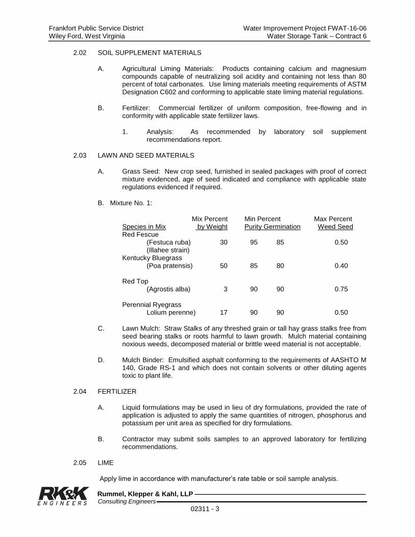
Frankfort Public Service District Water Improvement Project FWAT-16-06 Wiley Ford, West Virginia Water Storage Tank – Contract 6
Rummel, Klepper & Kahl, LLP Consulting Engineers
02311 - 3
2.02 SOIL SUPPLEMENT MATERIALS
A. Agricultural Liming Materials: Products containing calcium and magnesium compounds capable of neutralizing soil acidity and containing not less than 80 percent of total carbonates. Use liming materials meeting requirements of ASTM Designation C602 and conforming to applicable state liming material regulations.
B. Fertilizer: Commercial fertilizer of uniform composition, free-flowing and in conformity with applicable state fertilizer laws.
1. Analysis: As recommended by laboratory soil supplement recommendations report.
2.03 LAWN AND SEED MATERIALS
A. Grass Seed: New crop seed, furnished in sealed packages with proof of correct mixture evidenced, age of seed indicated and compliance with applicable state regulations evidenced if required.
B. Mixture No. 1:
Mix Percent Min Percent Max Percent Species in Mix by Weight Purity Germination Weed Seed
Red Fescue (Festuca ruba) 30 95 85 0.50 (Illahee strain)
Kentucky Bluegrass (Poa pratensis) 50 85 80 0.40 Red Top (Agrostis alba) 3 90 90 0.75 Perennial Ryegrass Lolium perenne) 17 90 90 0.50
C. Lawn Mulch: Straw Stalks of any threshed grain or tall hay grass stalks free from seed bearing stalks or roots harmful to lawn growth. Mulch material containing noxious weeds, decomposed material or brittle weed material is not acceptable.
D. Mulch Binder: Emulsified asphalt conforming to the requirements of AASHTO M 140, Grade RS-1 and which does not contain solvents or other diluting agents toxic to plant life.
2.04 FERTILIZER
A. Liquid formulations may be used in lieu of dry formulations, provided the rate of application is adjusted to apply the same quantities of nitrogen, phosphorus and potassium per unit area as specified for dry formulations.
B. Contractor may submit soils samples to an approved laboratory for fertilizing recommendations.
2.05 LIME
Apply lime in accordance with manufacturer’s rate table or soil sample analysis.

Frankfort Public Service District Water Improvement Project FWAT-16-06 Wiley Ford, West Virginia Water Storage Tank – Contract 6
Rummel, Klepper & Kahl, LLP Consulting Engineers
02311 - 4
2.06 INOCULANT
A. Inoculate leguminous seed before seeding with nitrogen fixing bacteria culture prepared specifically for the species.
B. Do not use inoculant later than the date indicated by the manufacturer.
C. Protect inoculated seed from prolonged exposure to sunlight prior to sowing.
D. Reinoculate seed not sown within 24 hours following initial inoculation.
2.07 EROSION CONTROL FABRIC
A. Shall be a knitted construction of yarn with uniform openings interwoven with strips of biodegradable paper, furnished in rolls with 4-mil opaque polyethylene base as protection for outdoor storage.
B. Fabric 0.2 pound per square yard.
2.08 JUTE MATTING
Shall be heavy weight, minimum 0.9 pound per square yard, jute mesh with 1" opening.
2.09 FABRIC/MATTING ANCHORS
Staples for fastening fabric to ground shall be minimum 11 gauge wire, “U” shaped, with a 1" crown and 6" legs.
2.10 MULCHING MATERIALS
A. Mulches for seeded areas shall be one, or a combination, of the following:
1. Timothy hay or mixed clover and timothy hay, or wheat, or oat straw; thoroughly threshed.
a. Cured to less than 20% moisture content by weight.
b. Containing no stems of tobacco, soybeans, or other coarse or woody material, free of mature seed bearing stalks or roots of prohibited or noxious weeds.
2. Wood Cellulose
a. Containing no growth or germination-inhibiting substances.
b. Green-dyed and air-dried.
c. Packages not exceeding 100 pounds.
d. Moisture Content: 12% + 3%
e. Organic Matter (Dry oven basis) 98.6% + 0.2%
f. Ash Content: 1.4% + 0.2%
g. Minimum Water-Holding Capacity: 100%

Frankfort Public Service District Water Improvement Project FWAT-16-06 Wiley Ford, West Virginia Water Storage Tank – Contract 6
Rummel, Klepper & Kahl, LLP Consulting Engineers
02311 - 5
3. Mushroom Manure:
a. Organic origin, free of foreign material larger than 2" and substances toxic to plant growth.
b. Organic Matter: 20% minimum
c. Water-Holding Capacity: 120% minimum
d. pH: 6.0
B. Mulch Binders
1. Emulsified Asphalt AASHTO M140, Grade SS-1.
2. Cut Back Asphalt AASHTO M81, RC 250.
3. Nonasphaltic Emulsion - Natural Vegetable Gum Blended with Gelling and Hardening Agents
4. Polyvinyl Acetate Emulsion Resin, Containing 60% (+ 1%) total Solids by Weight.
2.11 SOIL TREATMENT MATERIALS
A. Chemicals
1. Soil treatment chemicals shall be one of or equal to the following:
a. Dursban TC: To be used at a concentration of 1.0%, applied in water emulsion.
b. Dragnet TC: To be used at a concentration of 0.5%, applied in water emulsion.
c. Pryfon 6: To be used at a concentration of 0.75% applied in water emulsion.
2. Soil treatment chemicals used shall be mixed in the following proportions or as recommended by manufacture:
a. Dursban TC: 1.0% water emulsion, 2 gallons of Dursban TC per 98 gallons of water.
b. Dragnet TC: 0.5% water emulsion, 1.25 gallons of Dragnet TC per 98.75 gallons of water.
c. Pryfon 6: 0.75% water emulsion, 1 gallon of Pryfon 6 with 96 gallons of water.
PART 3 – EXECUTION
3.01 PREPARATION
A. Prepare subsoil surface for finish grading by dressing and shaping to provide for the uniform placement of topsoil.

Frankfort Public Service District Water Improvement Project FWAT-16-06 Wiley Ford, West Virginia Water Storage Tank – Contract 6
Rummel, Klepper & Kahl, LLP Consulting Engineers
02311 - 6
B. Prepare subsoil surface for top-soiling by loosening to a depth of four inches and dressing and shaping to provide for the uniform placement of topsoil.
C. Remove surface rock or other foreign objects exceeding 3/4 - inches in greatest dimension. Dispose of such rock and debris in a lawful manner off site.
3.02 PERFORMANCE
A. Placement: Place topsoil over areas indicated for new grading contours. However, before topsoil placement, construction work in top-soiled areas shall have been completed. Observe precautions as follows:
1. Do not place topsoil over areas indicated to receive paving or walkways.
2. Do not work topsoil while frozen or wet. Do not work topsoil in a dusting condition but moisten same to prevent a dust nuisance.
3. Scarify subsoil to a depth of two inches for bonding topsoil with subsoil.
4. On sloped areas, work topsoil into subsoil to blend so as to eliminate slip-planing between the two soils; but leave a sufficient cover of topsoil to insure seed germination. Perform such blending of soils by ridging or serrating the subsoil on the slopes.
5. Place topsoil as needed for dressing-up minor depressions due to settling and erosion and to eliminate other minor irregularities.
B. Finished Elevations and Lines: Grade top-soiled areas of the site to within a tolerance of plus or minus one-tenth of a foot of the elevations and lines indicated and in accordance with the following:
1. Grade a uniform longitudinal fall in swales and other surface drainage areas to provide a drainage flow line that can easily be maintained and traversed with normal lawn maintenance equipment.
2. Establish finish grade of topsoil 1/2 to 3/4 inch below top of abutting walks or paving to provide positive drainage of same.
3. Do not finish grade topsoil to a depth less than six inches nor greater than 12 inches.
4. Leave finish grade surfaces free of objectionable material larger than 3/4 - inches in greatest dimension. Dispose of such objectionable material in a legal disposal area off site.
C. Compaction: Compact finish grades as the final operation using a light roller weighing not over 120 pounds per foot-width of roller.
D. Tillage: Till finish graded soil over areas indicated for lawn regardless of type of lawn work performed. Use equipment and methods common to such work, and till soil to a two inch depth minimum.
E. Soil Supplement Addition: The soil supplements for lawn areas, as required according to the Engineer approved laboratory test reports, may be incorporated into the soil during tillage operations.

Frankfort Public Service District Water Improvement Project FWAT-16-06 Wiley Ford, West Virginia Water Storage Tank – Contract 6
Rummel, Klepper & Kahl, LLP Consulting Engineers
02311 - 7
F. Seeding: Sow seed mixtures when air current is low and not more than five days after soil supplements have been applied. Sow seeds in two applications using either mechanical power seeders or mechanical hand seeders. Sow one-half of the seed mixture in one direction over designated areas and the remainder at right angles to the first sowing. Seeding rates as follows:
1. Grass Seed Mixture: Five pounds per 1,000 sq. ft. area.
G. Seed Cover: Imbed seed mixtures into topsoil 1/4 inch using a light drag or rake and moving in directions parallel to the contour lines. Immediately after dragging or raking, compact seeded areas using a cultipacker or similar design lawn roller, weighing 60 to 90 pounds per linear foot of roller, and roll at right angles to existing slopes.
H. Contractor Option: Seeding and soil supplement application may be performed by the hydroseeding method. However, rates of application, methods and equipment shall receive Engineer's prior approval.
I. Lawn Mulching: Evenly apply mulch over seeded areas not more than 48 hours after seeding. Start mulching at windward side of relatively flat areas, or at the upper part of slopes. Spread mulch in a total coverage at a depth not less than 1-1/2 inches nor more than three inches.
I. Mulch Binding: Immediately following mulch spreading, apply mulch binder to anchor mulch to the soil. The number of passes over the mulch as needed to secure it firmly shall not exceed three passes with maximum applied binder not exceeding 10.0 gallons per 1,000 square feet.
3.03 MAINTENANCE
A. Maintenance operations shall begin immediately after seeding and shall continue throughout the construction time and guarantee period.
1. Seeded Areas: Keep seed moist continually for proper germination and water thereafter as necessary to prevent drying out or burning. Reseed areas not showing a prompt catch of grass, correct depressions and irregularities and reseed; repeat until a complete coverage is obtained. Cut seeded areas at required intervals to maintain grass at a maximum height of 2 1/2 inches.
B. At conclusion of maintenance period, the Engineer shall make an inspection of the lawn work to determine condition of acceptance. Make such additional repairs as required by the Engineer. Perform such work at no expense to the Owner.
END OF SECTION
Frankfort Public Service District Water Improvement Project FWAT-16-06 Wiley Ford, West Virginia Water Storage Tank – Contract 6
Rummel, Klepper & Kahl, LLP Consulting Engineers
02311 - 8
THIS PAGE LEFT BLANK

Frankfort Public Service District Water Improvement Project FWAT-16-06 Wiley Ford, West Virginia Water Storage Tank – Contract 6
Rummel, Klepper & Kahl, LLP Consulting Engineers
02315 - 1
SECTION 02315
TRENCHING, BACKFILLING, AND COMPACTING
PART 1 - GENERAL
1.01 DESCRIPTION
A. The Work of This Section Includes, But Is Not Limited To
1. Trench excavation, backfill and compaction
2. Support of excavation
3. Pipe bedding requirements
4. Control of excavated material
5. Restoration of unpaved surfaces
B. Related Work Specified Elsewhere
1. Section 02230 - Clearing and Grubbing
2. Section 02300 - Earthwork
3. Section 02311 - Finish Grading and Seeding
4. Section 02740 – Paving and Surfacing
5. Section 02535 - Pipe and Pipe Fittings
C. Applicable Standard Details
1. Pipe Bedding Details
2. Pipe Trench Detail
3. Concrete Cradle and Encasement Details
4. Thrust Block for Vertical Bends
5. Thrust Block for Bends, Tees, and Caps
1.02 QUALITY ASSURANCE
A. Testing Agency: Density testing shall be performed by an independent soils testing laboratory engaged and paid for by the Contractor and approved by the Engineer.
B. Referenced Standards
1. American Society for Testing and Materials (ASTM)
a. D698 Test Method for Laboratory Compaction Characteristics of Soil Using Standard Effort
b. D1556 Test Method for Density and Unit Weight of Soil in Place by the Sand Cone Method

Frankfort Public Service District Water Improvement Project FWAT-16-06 Wiley Ford, West Virginia Water Storage Tank – Contract 6
Rummel, Klepper & Kahl, LLP Consulting Engineers
02315 - 2
c. D1557 Test Method for Laboratory Compaction Characteristics of Soil Using Modified Effort
d. D2922 Test Methods for Density of Soil and Soil Aggregate in Place by Nuclear Methods
C. Density Testing
1. Conduct one test for each 1,000 linear feet of pipeline. Conduct density tests at locations as directed by the Engineer during backfilling operations.
2. Determine density by ASTM D1556 or ASTM D2922 in areas other than State Highways and Shoulders.
1.03 SUBMITTALS
A. General: Submit in accordance with Section 01300.
B. Certificates
1. Submit, prior to delivery of the material to the job site, a Statement of Compliance from the materials supplier, together with supporting data, attesting that the composition analysis of pipe bedding and select material stone backfill materials meets specification requirements. Should a change in source of materials be made during construction, submit a new Statement of Compliance from the new source for approval before the material is delivered to the job site.
2. Submit certified density testing results from the soils testing laboratory.
C. Compaction Equipment List: Submit a list of all equipment to be utilized for compacting, including the equipment manufacturer’s lift thickness limitations.
D. Agreements with Property Owners: Prior to storing or disposing of excavated materials on private property, submit a copy of the written agreement with the property owner.
1.04 JOB CONDITIONS
A. Classification of Excavation: All excavation work performed under this contract is unclassified, and includes excavation and removal of all soil, shale, rock boulders, fill, and all other materials encountered of whatever nature.
B. Protection of Existing Utilities and Structures:
1. Take all precautions and utilize all facilities required to protect existing utilities and structures. Advise each Utility at least 3 working days in advance of intent to excavate, do demolition work and give the location of the job site. Request cooperative steps of the Utility and suggestions for procedures to avoid damage to its lines.
2. Advise each person in physical control of powered equipment used in excavation or demolition work of the type and location of utility lines at
Frankfort Public Service District Water Improvement Project FWAT-16-06 Wiley Ford, West Virginia Water Storage Tank – Contract 6
Rummel, Klepper & Kahl, LLP Consulting Engineers
02315 - 3
the job site, the Utility assistance to expect and procedures to follow to prevent damage.
3. Immediately report to the Utility and the Engineer any break, leak or other damage to the lines or protective coatings made or discovered during the work and immediately alert the occupants of premises of any emergency created or discovered.
4. Allow free access to Utility personnel at all times for purposes of maintenance, repair and inspection.
PART 2 - PRODUCTS
2.01 PIPE BEDDING MATERIAL
Bedding Material: Clean granular material meeting the requirements of AASHTO M 43 size No. 8 on detail or as approved by the Engineer.
2.02 BACKFILL MATERIAL
A. Granular material conforming to the Uniform Soil Classification Groups GW, GP, SW or SP that will completely pass a (1 1/2") sieve and that will compact readily when the usual methods of tamping are used. It shall conform to the requirements of AASHTO M 43, size number 57 and have a maximum Los Angeles Abrasion (LA) test (AASHTO T-96) of 50%.
B. Suitable Backfill Material
1. From top of pipe bedding material to 24" over top of pipe
a. Material excavated from the trench if free of stones larger than 2" in size and free of wet, frozen, or organic materials.
2. From 24" above pipe bedding to subgrade elevation
a. Material excavated from the trench if free of stones larger than 6" in size and free of wet, frozen, or organic materials.
C. Unsuitable Backfill Material: where the Engineer deems backfill material to be unsuitable and rejects all or part thereof due to conditions prevailing at the time of construction, remove the unsuitable material and replace with select material stone backfill as specified in paragraph 2.02A or suitable foreign backfill material.
PART 3 - EXECUTION
3.01 MAINTENANCE AND PROTECTION OF TRAFFIC
A. Coordinate the work to ensure the least inconvenience to traffic and maintain traffic in one or more unobstructed lanes unless closing the street is authorized.
B. Maintain access to all streets and private drives.
C. Provide and maintain signs, flashing warning lights, barricades, markers, and other protective devices as required to conform to construction operations and to keep traffic flowing with minimum restrictions.

Frankfort Public Service District Water Improvement Project FWAT-16-06 Wiley Ford, West Virginia Water Storage Tank – Contract 6
Rummel, Klepper & Kahl, LLP Consulting Engineers
02315 - 4
D. Comply with State and local codes, permits and regulations.
3.02 CUTTING PAVED SURFACES
A. Where excavation includes breaking a paved surface, make cuts in a neat uniform fashion forming straight lines parallel with the centerline of the trench. Cut offsets at right angles to the centerline of the trench. Saw cut concrete surfaces; saw cut other hard surfaces or make straight cuts with jackhammer. No paving shall be broken except that which has been previously cut.
B. Protect edges of cut pavement during excavation to prevent raveling or breaking; square edges prior to pavement replacement.
3.03 BLASTING
No blasting will be permitted without prior written approval of Engineer
3.04 TRENCH EXCAVATION
A. Topsoil Stripping and Stockpiling: Strip topsoil encountered during trench excavation to its full depth and stockpile for reuse.
B. Depth of Excavation
1. Gravity Pipelines: Excavate trenches to the depth and grade shown on the profile drawings for the invert of the pipe plus that excavation necessary for placement of pipe bedding material.
2. Pressure Pipelines:
a. Excavate trenches to the minimum depth necessary to place required pipe bedding material and to provide 4' from the top of the pipe to the finish ground elevation, except where specific depths are otherwise indicated on the Contract Drawings.
b. Where unsuitable bearing material is encountered in the trench bottom, continue excavation until the unsuitable material is removed, solid bearing is obtained or can be established, or concrete cradle can be placed. If no concrete cradle is to be installed, refill the trench to required pipeline grade with pipe bedding material or other material approved by Engineer.
c. Where the Contractor, by error or intent, excavated beyond the minimum required depth, backfill the trench to the required pipeline grade with pipe bedding material or crusher run as directed by Engineer.
C. Width of Excavation
1. Excavate trenches to a width necessary for placing and jointing the pipe and for placing and compacting bedding and backfill around the pipe.
2. Shape trench walls completely vertical from trench bottom to at least 24" above the top of pipe.

Frankfort Public Service District Water Improvement Project FWAT-16-06 Wiley Ford, West Virginia Water Storage Tank – Contract 6
Rummel, Klepper & Kahl, LLP Consulting Engineers
02315 - 5
3. For pressure pipeline fittings, excavate trenches to a width that will permit placement of concrete thrust blocks. Provide original earth surfaces for thrust blocks that are perpendicular to the direction of thrust and are free of loose or soft material.
4. Where rock is encountered in the sides of the trench, remove the rock to provide a minimum clearance between the pipe and rock of 6".
D. Length of Open Trench: Do not advance trenching operations more than 50' ahead of completed pipeline. No open trench shall be left overnight without approval of Engineer and adequate safety safeguards.
3.05 SUPPORT OF EXCAVATION
A. Support excavations with sheeting, shoring, and bracing or a “trench box” as required to comply with Federal and State laws and codes. Install adequate excavation supports to prevent ground movement or settlement to adjacent structures, pipelines or utilities. Damage due to settlement because of failure to provide support or through negligence or fault of the Contractor in any other manner shall be repaired at the Contractor’s expense.
B. Withdraw shoring, bracing, and sheeting as backfilling proceeds unless otherwise directed by the Engineer.
3.06 CONTROL OF EXCAVATED MATERIAL
A. Keep the ground surface within a minimum of 2' of both sides of the excavation free of excavated material.
B. In areas where pipelines parallel or cross streams, ensure that no material slides, is washed, or dumped into the stream course. Remove cofferdams immediately upon completion of pipeline construction.
C. Where crossing wetlands, as shown on plans, top one (1) foot of excavated material shall be segregated and used to backfill the final one (1) foot of the ditch. Contractor shall use care when crossing wetlands to prevent construction of French drains allowing the wetlands to dewater. For additional requirements on crossing wetlands refer to Army Corp of Engineers and PLC Permit in Appendix C.
D. Maintain accessibility to all fire hydrants, valve pit covers, valve boxes, curb boxes and other utility controls at all times. Keep gutters clear or provide other satisfactory facilities for street drainage. Do not obstruct natural watercourses. Where necessary, provide temporary channels to allow the flow of water either along or across the site of the work.
E. Provide temporary barricades to prevent excavated material from encroaching on private property, walks, gutters, and storm drains.

Frankfort Public Service District Water Improvement Project FWAT-16-06 Wiley Ford, West Virginia Water Storage Tank – Contract 6
Rummel, Klepper & Kahl, LLP Consulting Engineers
02315 - 6
3.07 DEWATERING
A. Keep excavations dry and free of water. Dispose of precipitation and subsurface water so as to not disrupt or re-saturate the work area.
B. Maintain pipe trenches dry until pipe has been jointed, inspected, and backfilled, and concrete work has been completed. Prevent trench water from entering pipelines under construction.
C. Intercept and divert surface drainage away from excavations. Maintain storm drainage facilities, gutters, and natural surface watercourses open and in operation. Provide and install temporary facilities to maintain excavations free of water as required. Design surface drainage systems so as to not cause erosion on or off the site, or cause unwanted flow of water. When mechanical equipment is utilized to control water conditions, provide and maintain sufficient standby units onsite.
D. Comply with Federal and State requirements for dewatering to any watercourse, prevention of stream degradation, and erosion and sediment control. Comply with the Sediment and Erosion Control Plan whether required control and prevention methods are explicitly shown on plans or not.
3.08 PIPE BEDDING REQUIREMENTS
Refer to Drawings.
3.09 PIPE LAYING
Lay pipe as specified in the appropriate Section of these Specifications for pipeline construction.
3.10 THRUST RESTRAINT
Provide pressure pipe with concrete thrust blocking or use restrained joint fittings at all bends, tees, valves, and changes in direction, in accordance with the Specifications, Contract Drawings, Standard Details, and pipe manufacturer recommendations.
3.11 BACKFILLING TRENCHES
A. After pipe installation and inspection, backfill trenches from trench bottom or from the top of pipe bedding material, whichever is greater, to 12" above the crown of the pipe with specified backfill material hand placed and carefully compacted with hand-operated mechanical tampers in layers of suitable thickness to provide specified density around and under the haunches of the pipe. Backfill and compact the remainder of the trench with specified backfill material.
B. Lift thickness Limitations
1. In no case shall maximum lift thickness placed exceed the maximum limits specified by the pipe manufacturer’s recommendations. However, if the Contractor’ equipment manufacturer’s lift thickness recommendation is followed and the specified density is not obtained, the Contractor shall, at his own expense, remove, replace, and retest as many times as is required to obtain the specified density.
Frankfort Public Service District Water Improvement Project FWAT-16-06 Wiley Ford, West Virginia Water Storage Tank – Contract 6
Rummel, Klepper & Kahl, LLP Consulting Engineers
02315 - 7
2. Compact each layer of material to 95% of the maximum density at + two percent (+2%) of the optimum moisture content as determined by ASTM D698.
3. Notwithstanding the specified requirements for trench backfill compaction, trenches that settle below the surrounding grade prior to final completion shall be filled to surrounding grade level with appropriate materials.
3.12 UTILITY MARKING TAPE
Install detectable utility marking tape as specified in Section 15060 above all plastic pipelines, 12"-18" below final grade.
3.13 DISPOSAL OF EXCAVATED MATERIAL
Excavated material remaining after completion of backfilling shall remain the property of the Contractor, removed from the construction area and legally disposed.
3.14 RESTORATION OF UNPAVED AREAS
A. Restore unpaved surfaces disturbed by construction to match the final grade shown on the Contract Drawings.
B. Restore grassed areas in accordance with Section 02485, Finish Grading and Seeding.
END OF SECTION

Frankfort Public Service District Water Improvement Project FWAT-16-06 Wiley Ford, West Virginia Water Storage Tank – Contract 6
Rummel, Klepper & Kahl, LLP Consulting Engineers
02315 - 8
THIS PAGE LEFT BLANK

Frankfort Public Service District Water Improvement Project FWAT-16-06 Wiley Ford, West Virginia Water Storage Tank – Contract 6
Rummel, Klepper & Kahl, LLP Consulting Engineers
02316 - 1
SECTION 02316
ROADWAY EXCAVATION, BACKFILLING, AND COMPACTING
PART 1 - GENERAL
1.01 DESCRIPTION
A. The Work of This Section Includes, But Is Not Limited To
1. Roadway Subgrade: The prepared earth surfaces on or over which additional roadway materials will be placed or work is to be performed.
B. Related Work Specified Elsewhere
1. Section 02230 - Clearing and Grubbing
2. Section 02300 - Earthwork
3. Section 02311 - Finish Grading and Seeding
4. Section 02740 - Paving and Surfacing
1.02 QUALITY ASSURANCE
A. Testing Agency: Density testing shall be performed by an independent soils testing laboratory engaged and paid for by the Contractor and approved by the Engineer.
B. Referenced Standards
1. American Society for Testing and Materials (ASTM)
a. AASHTO T-99, Moisture-Density Relations of Soils and Soil-Aggregate Mixtures, Using a 5.5 lb. Rammer and a 12 in. Drop.
b. AASHTO T-180, Moisture-Density Relations of Soils and Soil-Aggregate Mixtures, Using a 10 lb. Rammer and an 18 in. Drop.
c. ASTM D 1556, Density of Soil In-Place by the Sand Cone Method.
d. ASTM D 2922, Density of Soil and Soil Aggregate in Place by Nuclear Methods (Shallow Depth).
e. ASTM D 3017, Moisture Content of Soil and Soil-Aggregate in Place by Nuclear Methods (Shallow Depth).
f. AASHTO T-96, Los Angeles Abrasion test for aggregates.
C. West Virginia Department of Transportation, Division of Highways (WVDOH) Standard Specifications and all supplements thereto.
Frankfort Public Service District Water Improvement Project FWAT-16-06 Wiley Ford, West Virginia Water Storage Tank – Contract 6
Rummel, Klepper & Kahl, LLP Consulting Engineers
02316 - 2
1.03 SUBMITTALS
A. General: Submit in accordance with Section 01300.
B. Samples: Submit aggregate samples to the Engineer's Field Office. Make such other required submissions to the Engineer's Business Office street address.
1. Aggregates: Submit four (4) 25 pound samples, packaged in container of suitable strength, for Engineer's verification and certification for submission to testing laboratory. One set of samples shall be submitted for West Virginia Division of Highways materials and one set of samples shall be submitted for materials.
C. Test Reports:
1. Submit testing laboratory aggregate test reports based on requirements stated in Source Quality Control for West Virginia.
2. Compaction density test reports based on method of density determination as specified in Reference Standards and the method as approved by the Engineer.
3. Contractor’s submittal shall include test results from a certified laboratory that documents the crushed stone bedding backfill is non-corrosive to metal pipe by means of “corrosivtivity test”.
D. Certificates: Submit certificate from aggregate supplier based on requirements stated in Source Quality Control.
E. Geosynthetic Materials: Refer to Section on Geosynthetics for requirements of materials to be used herein.
1.04 SITE CONDITIONS
A. Environmental Requirements: Do not perform roadway excavation, backfill and compaction when soil or weather conditions are unsuitable. Unsuitable conditions include moisture saturated or frozen in place soil and precipitation present on the soil or occurring during the Work.
B. Dust Control: Exercise the necessary means and methods to control dust on the site during the roadway excavation, backfill and compaction work.
C. Excess Materials: No right of property in materials is granted the Contractor of excess on site materials prior to completion of Site Grading Work. This provision does not relieve the Contractor of his responsibility to remove and dispose of surplus excavated materials. Materials unsuitable for roadway subgrade and not suitable for other uses on-site shall become the property of the Contractor and shall be disposed of in a lawful manner off-site.
D. Contractor shall pay strict attention to location of work being accomplished (ie. State Highway Administration Right of way) to ensure that work being accomplished is in accordance with proper standard specifications for Roads and Bridges.

Frankfort Public Service District Water Improvement Project FWAT-16-06 Wiley Ford, West Virginia Water Storage Tank – Contract 6
Rummel, Klepper & Kahl, LLP Consulting Engineers
02316 - 3
PART 2 - PRODUCTS
2.01 MATERIALS
A. Backfill: Use crushed stone aggregate conforming to the following requirements:
1. West Virginia Department of Transportation, Division of Highways (WVDOH) Standard Specifications and all supplements thereto.
B. The sieve analysis of the above shall be in accordance with State standard for material selected.
PART 3 - EXECUTION
3.01 PERFORMANCE
A. Perform soil erosion control work in accordance with requirements as specified.
B. Roadway Excavation: Excavate or otherwise remove and satisfactorily dispose of materials located within the limits indicated on the Drawings.
1. Excavate to roadway subgrade depths required, and cut drainage channels and waterways as detailed.
2. Remove rock encountered in roadway excavation to a depth six inches below finished subgrade elevations.
3. Excavate subgrade material determined unsatisfactory in the opinion of the Engineer. Refill such areas to required elevation with Backfill as specified herein, placed in loose lifts no more than 6 inches thick and compact to 95 percent of the maximum dry density according to AASHTO T-180 at its optimum moisture content plus or minus 2 percentage points.
C. Roadway Grading: Shape subgrade of roadways, intersections, approaches, entrances and adjoining pedestrian walkways to no more than 0.10 foot above or below the elevations indicated on the Drawings or required to match existing adjacent roadway surface elevations.
D. Roadways Embankments: Construct embankments for roadways as specified.
E. Compaction: Compact subgrade material to a minimum final density of not less than 95 percent of the maximum dry weight density according to AASHTO T-180 at its optimum moisture content plus or minus 5 percentage points. Perform proof rolling on roadway subgrade just prior to installation of aggregate base course to ensure correct compaction percentage prior to proceeding with base course. Density and compaction tests required by the Engineer will be at the Contractor's expense.
F. Roadway Base Course Construction: Final subgrade preparation and roadway base course construction as specified.
Frankfort Public Service District Water Improvement Project FWAT-16-06 Wiley Ford, West Virginia Water Storage Tank – Contract 6
Rummel, Klepper & Kahl, LLP Consulting Engineers
02316 - 4
3.02 FIELD QUALITY CONTROL
A. Surface Tolerance: Check finished subgrade surface for smoothness and elevation in accordance with the following:
1. Use an approved template shaped to conform to the design requirement indicated on the Drawings for checking crown and contour of roadways.
2. Use an approved ten foot straightedge to check for longitudinal irregularities in the subgrade.
3. Use string lines for controlling the finished elevation of roadway subgrade. Maintain such lines until surface irregularities have been satisfactorily corrected.
B. Corrections: Correct surface irregularities exceeding previously specified limits to the Engineer's satisfaction either by removing or adding material as required, followed by rolling until satisfactorily compacted.
END OF SECTION

Frankfort Public Service District Water Improvement Project FWAT-16-06 Wiley Ford, West Virginia Water Storage Tank – Contract 6
Rummel, Klepper & Kahl, LLP Consulting Engineers
02370 - 1
SECTION 02370
EROSION CONTROL DURING CONSTRUCTION
PART 1 - GENERAL
1.01 RELATED DOCUMENTS
A. General
Drawings and general provisions of the Contract, including General and Supplementary conditions and Division 1 specification sections, apply to this section.
B. Referenced Sections
1. Grading and Seeding.
1.02 DESCRIPTION OF WORK
The contractor shall provide the soil erosion controls as specified herein. The cost of all erosion control measures shall be included in the appropriate Bid Items described in the Prices to Include. The Owner shall be responsible for obtaining the necessary NPDES Permit(s) for construction of the erosion and sediment control during construction. Contractor is responsible for securing and permitting off-site waste and borrow areas.
1.03 QUALITY ASSURANCE
A. Scheduling
Where erosion is likely to be a problem, clearing and grubbing operations should be so scheduled and performed that grading operations and permanent erosion control features can follow immediately thereafter if the project conditions permit; otherwise temporary erosion control measures will be required between successive construction stages. These erosion control measures shall be maintained in effective operating condition during construction until final grading and seeding occurs. Special attention must be given to dewatering activities to minimize release of silt-laden water off-site. The sediment free flows shall only be released into storm sewers, stream channels, or other stabilized drainage receptors and not onto exposed soils or any other site where flows could cause further erosion.
B. Dust Control.
Dust generation shall be minimized, including wetting down of paved and unpaved areas during the construction activities.
C. Operation Limits
The Engineer will delineate the area of excavation and backfilling operations in progress commensurate with the Contractor's capability and progress in keeping the finished grading, mulching, seeding, and other such temporary or permanent control measures current in accordance with the specifications. Should seasonal
Frankfort Public Service District Water Improvement Project FWAT-16-06 Wiley Ford, West Virginia Water Storage Tank – Contract 6
Rummel, Klepper & Kahl, LLP Consulting Engineers
02370 - 2
limitations make permanent control measures unrealistic, temporary erosion control measures including seeding and mulching shall be taken immediately. Surplus excavated material and equipment storage is prohibited within 200 feet of any stream bank, in wooded areas, or in other environmentally sensitive areas. Surplus excavated materials shall be disposed of at site approved by the Owner.
D. Site containment
Site access will be limited and protected by the Contractor to prevent off-site tracking of soil and sediment by construction traffic. Any off-site tracking of soil and sediment will be cleaned up immediately to prevent any sedimentation escaping off-site.
E. Conflicts
1, In the event of conflict between these requirements and pollution control laws, rules, or regulations of other Federal or State or local agencies, the more restrictive laws, rules, or regulations shall apply.
2. Notes or specific requirements listed on plans shall govern if more restrictive than these specifications.
F. Reference Standards
1. WV DEP – West Virginia Department of Environmental Protection
2. WVDOH – West Virginia Department of Transportation, Division of Highways
3. Soil Conservation Service (Natural Resources Conservation Service)
1.04 SUBMITTALS
Not used.
1.05 JOB CONDITIONS
A. General
The contractor shall limit the surface area of erodible earth material exposed by the clearing and grubbing, excavation, and backfill operations and provide permanent or temporary control measures to prevent contamination of adjacent streams or other water courses, lakes, ponds, or other areas of water impoundment. Such work will involve the use of temporary and/or permanent mulches, mats, seeding or other control and contain devices or methods necessary to control erosion and sedimentation. If work is suspended for any reason, the Contractor shall maintain the soil erosion and sedimentation controls in good operating condition during the suspension of the work. Also, when the suspension of work is expected to exceed a period of 7 days, the Contractor shall temporary seed, fertilize, and mulch all disturbed areas left exposed when the work is stopped.
B. Permanent Erosion control
The Contractor shall incorporate all permanent erosion control features into the
Frankfort Public Service District Water Improvement Project FWAT-16-06 Wiley Ford, West Virginia Water Storage Tank – Contract 6
Rummel, Klepper & Kahl, LLP Consulting Engineers
02370 - 3
project at the earliest practicable time. Except where future construction operations will damage slopes, the Contractor shall perform the permanent fertilizing, seeding and mulching as soon as substantial areas can be made available. This will require the establishing of final grades and application of fertilizer, seeding and mulching. No areas where construction is completed shall be left for longer than 7 days without, as a minimum, temporary fertilizer seeding and mulching. Any disturbed area that will not be actively under construction for a period of 7 days or more shall be temporarily stabilized immediately by fertilizer, seeding and mulching.
1.06 DELIVERY, STORAGE, AND HANDLING
Not used.
1.07 SPECIAL WARRANTY
Not used.
PART 2 - PRODUCTS
2.01 FERTILIZER, SEED AND MULCH
A. General
All products utilized for erosion control purposes shall be provided in accordance with the requirements of specifications.
PART 3 - EXECUTION
3.01 FERTILIZER, SEED AND MULCH
A. General
All erosion control work shall be executed in accordance with specifications.
3.02 SEDIMENT BARRIERS
A. Filter Barriers (FB)
The filter barrier may be constructed using burlap or standard strength synthetic filter fabric. It is designed for low or moderate flows not exceeding 1 cfs.
1. The height of a filter barrier shall be a minimum of 15 inches and shall not exceed 18 inches.
2. Burlap or standard strength synthetic filter fabric shall be purchased in a continuous roll and cut to the length of the barrier to avoid the use of joints (and thus improve the strength and efficiency of the barrier).
3. The stakes shall be spaced a maximum of 3 feet apart at the barrier location and driven securely into the ground (minimum of 8 inches).
4. A trench shall be excavated approximately 4 inches wide and 4 inches deep along the line of stakes and upslope from the barrier.
Frankfort Public Service District Water Improvement Project FWAT-16-06 Wiley Ford, West Virginia Water Storage Tank – Contract 6
Rummel, Klepper & Kahl, LLP Consulting Engineers
02370 - 4
5. The filter material shall be stapled to the wooden stakes, and 8 inches of the fabric shall be extended into the trench. Heavy-duty wire staples at least 1/2 inch shall be used. Filter material shall not be stapled to existing trees.
6. The trench shall be backfilled and the soil compacted over the filter material.
7. If a filter barrier is to be constructed across a ditch line or swale, the barrier shall be of sufficient length to eliminate end flow, and the plan configuration shall resemble an arc or horseshoe with the ends oriented upslope.
8. Filter barriers shall be removed when they have served their useful purpose, but not before the upslope area has been permanently stabilized.
B. Silt Fence (SF)
The silt fence uses a standard strength or extra strength synthetic filter fabrics. It is designed for situations in which only sheet or overland flows are expected.
1. The height of a silt fence shall not exceed 36 inches (higher fences may impound volumes of water sufficient to cause failure of the structure).
2. The filter fabric shall be purchased in a continuous roll cut to the length of the barrier to avoid the use of joints. When joints are necessary, filter cloth shall be spliced together only at a support post, with a minimum 6-inch overlap, and securely sealed.
3. Posts shall be spaced a minimum of 10 feet apart at the barrier location and driven securely into the ground (minimum of 12 inches). When extra strength fabric is used without the wire support fence, post spacing shall not exceed 6 feet.
4. A trench shall be excavated approximately 4 inches wide and 4 inches deep along the line of posts and upslope from the barrier.
5. When standard strength filter fabric is used, a wire mesh support fence shall be fastened securely to the upslope side of the posts using heavy duty wire staples at least 1 inch line, tie wires or hog rings. The wire shall extend into the trench a minimum of 2 inches and shall not extend more that 36 inches above the original ground surface.
6. The standard strength filter fabric shall be stapled or wired to the fence, and 8 inches of the fabric shall be extended into the trench. The fabric shall not extend more than 36 inches above the original ground surface. Filter fabric shall not be stapled to existing trees.
7. When extra strength filter fabric and closer post spacing are used, the wire mesh support fence may be eliminated. In such a case, the filter fabric is stapled or wired directly to the posts with all other provisions of item No. 6 applying.
8. The trench shall be backfilled and soil compacted over the filter fabric.

Frankfort Public Service District Water Improvement Project FWAT-16-06 Wiley Ford, West Virginia Water Storage Tank – Contract 6
Rummel, Klepper & Kahl, LLP Consulting Engineers
02370 - 5
9. Silt fences shall be removed when they have served their useful purpose, but not before the upslope area has been permanently stabilized.
C. Maintenance
1. Silt fences and filter barriers shall be inspected immediately after each rainfall and at least daily during prolonged rainfall. Any required repairs shall be made immediately.
2. Should the fabric on a silt fence or filter barrier decompose or become ineffective prior to the end of the expected useable life and the barrier is still necessary, the fabric shall be replaced promptly.
3. Sediment deposits should be removed after each storm event. They must be removed when deposits reach approximately one-half the height of the barrier.
4. Any sediment deposit remaining in place after the silt fence or filter barrier is no longer required shall be dressed to conform with the existing grade, prepared and seeded.
3.03 MATTING
Matting shall be provided on all final slopes 3:1 or greater and bottom of drainage ditches.
3.04 TOP SOIL STOCKPILES –
The Contractor may stockpile topsoil in accordance with these plans and specifications. The Contractor shall provide temporary drainage diversion of runoff around the stockpile to control soil erosion and in accordance with MDSHA Standard Construction Drawings. Stockpiled topsoil shall be protected through the use of temporary seeding and mulching or covering such as with anchored straw mulch. Silt barriers shall be installed down gradient of these areas on contour and with their ends up slope of the contour to prevent silt-laden runoff from entering waterways or storm sewers. Within 7 days of completion of construction, any remaining soil shall either be removed or permanently stabilized.
3.05 STREAM BANKS
If construction results in the disturbance of a stream bank, it shall be restored, graded, seeded and mulched in accordance with the specifications immediately upon completion of the work crossing the stream.
END OF SECTION

Frankfort Public Service District Water Improvement Project FWAT-16-06 Wiley Ford, West Virginia Water Storage Tank – Contract 6
Rummel, Klepper & Kahl, LLP Consulting Engineers
02370 - 6
THIS PAGE LEFT BLANK
Frankfort Public Service District Water Improvement Project FWAT-16-06 Wiley Ford, West Virginia Water Storage Tank – Contract 6
Rummel, Klepper & Kahl, LLP Consulting Engineering
02505 - 1
SECTION 02505
UTILITY RELOCATION
PART 1 - GENERAL
1.01 DESCRIPTION
A. Work Included:
1. Utilities are those services, as listed immediately following, which are located near enough to the Project site that construction operations may require relocation or temporary supporting of the utility. Utility relocations shall be incidental to other items.
a. Water Service
b. Wastewater Sewer Service
c. Telephone Service
d. Electric Service
e. Natural Gas
f. Storm Drain Culverts
1.02 RELATED WORK
A. 02315 - Trenching, Backfilling and Compacting
B. Division 3 - Concrete
1.03 QUALITY ASSURANCE
A. Source Quality Control: Use products of companies having established reputations in the manufacture of the particular materials, equipment, or apparatus specified. Such products may be of their own make, or products of others for which they assume full responsibility when used in said outfits (which are not manufactured completely by them), and with replacement parts available.
B. Requirements of Regulatory Agencies:
1. General Requirement: comply with construction requirements of State, County, or other political subdivision, which requirements exceed these specifications.
2. Service interruptions are to be kept to a minimum and are to be at all times directed by the Owner of the utility. In order to keep the down time to a minimum, the Contractor shall complete as much of the work as possible prior to the interruption.
3. Certificates and Permits: Upon completion of work, and prior to final payment, furnish formal certification of final inspections to the Engineer

Frankfort Public Service District Water Improvement Project FWAT-16-06 Wiley Ford, West Virginia Water Storage Tank – Contract 6
Rummel, Klepper & Kahl, LLP Consulting Engineering
02505 - 2
from authorities having jurisdiction and secure required permits or certificates (if any) from such authorities. Additionally, prepare detailed diagrams and drawings which may be required by those authorities having jurisdiction.
1.04 SUBMITTALS
A. Shop Drawings and Product Data:
1. Manufacturer's published detail drawings, modified to suit design conditions if required, and Contractor prepared drawings as applicable.
2. Manufacturer's descriptive literature and specifications covering the product required. Include installation information.
1.05 SITE CONDITIONS
A. Environmental Requirements:
1. Keep trenches dewatered until pipe joints have been made and concrete work, if any, has cured.
2. Under no circumstances lay pipe (or conduit) in water or on bedding containing frost.
3. Do not lay pipe (or conduit) when weather conditions are unsuitable, as determined by the Engineer, for pipe (or conduit) laying work.
B. Protection:
1. Exercise care during utility uncovering and connecting work to confine operations to the facilities as indicated on the Drawings. The physical means and methods used for protection are at the Contractor's option. However, the Contractor will be completely responsible for replacement and restitution work of whatever nature to adjacent structures and construction.
2. Exercise every precaution against flotation of both existing and new pipe (or conduit) and in-line or on-line structures. Correct damage from flotation to the satisfaction of the Engineer.
PART 2 – PRODUCTS
2.01 MATERIALS
A. Provide materials and equipment (Products) for incorporation in the work that are new and unused standard products of recognized reputable manufacturers.
1. For each category of Products, provide Products of the same manufacturer and type.
2. Provide Products that match existing materials and are suitable for the type of service required.

Frankfort Public Service District Water Improvement Project FWAT-16-06 Wiley Ford, West Virginia Water Storage Tank – Contract 6
Rummel, Klepper & Kahl, LLP Consulting Engineering
02505 - 3
B. Trenching and Backfilling Materials: Conforming to requirements of Section 02315.
PART 3 - EXECUTION
3.01 INSPECTION
A. Inspect each section or length of pipe (and conduit), and each fitting, before laying for defects that would affect performance.
B. Promptly remove rejected Products from the Project site.
3.02 PREPARATION
A. Field Measurement:
1. The Drawings are in general indicative of the Work with symbols and notations for clarity. However, the Drawings are not an exact representation of all conditions involved, therefore, layout piping to suit actual field measurements. No extra compensation will be made for Work due to differences between indicated and actual dimensions.
2. Submit details of proposed departures necessitated by field conditions or other causes to Engineer for approval.
B. Earthwork: Perform earthwork for buried piping (and conduit) as specified in Trenching, Backfilling and Compaction, Section 02315:
1. Rest each section of pipe on pipe bedding for the full length of its barrel, with recesses excavated for pipe joints so joints can easily be made.
2. Backfill recesses with bedding material immediately following pipe joining operations.
3.03 RELOCATION
A. General Requirements:
1. Use only the proper and suitable tools and apparatus for proper and safe handling, lowering into trench and laying of pipes (and conduit).
2. Clean piping (and conduit) interior prior to installation and following installation. Keep open ends of piping (and conduit) attachment openings on equipment capped or plugged until actual connection.
3. Construct piping (and conduit) from full lengths of pipe (and conduit) using short sections only for runs of less than full pipe (and conduit) length.
4. Use reducing fittings where reduction in pipe sizes is necessary. Bushings will not be accepted.
5. Take up and relay pipe that is not laid true to required alignment or grade or has its joints disturbed after laying. No deviation from the required line and grade permitted, except with approval of the Engineer.
Frankfort Public Service District Water Improvement Project FWAT-16-06 Wiley Ford, West Virginia Water Storage Tank – Contract 6
Rummel, Klepper & Kahl, LLP Consulting Engineering
02505 - 4
6. Pipe Joining: Exercise care when making the pipe joints and make joints in accordance with the pipe material manufacturer's recommendations and the following requirements. In each instance of pipe joining, those portions of pipes involved must be absolutely clean just prior to assembly. If a joint is extremely difficult to assemble or sealing is not effected, disassemble the joint and correct the difficulty if possible. Remake the joint using new materials when necessary.
END OF SECTION
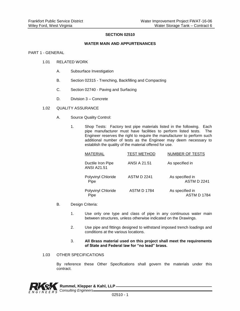
Frankfort Public Service District Water Improvement Project FWAT-16-06 Wiley Ford, West Virginia Water Storage Tank – Contract 6
Rummel, Klepper & Kahl, LLP Consulting Engineers
02510 - 1
SECTION 02510
WATER MAIN AND APPURTENANCES PART 1 - GENERAL
1.01 RELATED WORK
A. Subsurface Investigation
B. Section 02315 - Trenching, Backfilling and Compacting
C. Section 02740 - Paving and Surfacing
D. Division 3 – Concrete
1.02 QUALITY ASSURANCE
A. Source Quality Control:
1. Shop Tests: Factory test pipe materials listed in the following. Each pipe manufacturer must have facilities to perform listed tests. The Engineer reserves the right to require the manufacturer to perform such additional number of tests as the Engineer may deem necessary to establish the quality of the material offered for use.
MATERIAL TEST METHOD NUMBER OF TESTS
Ductile Iron Pipe ANSI A 21.51 As specified in ANSI A21.51
Polyvinyl Chloride ASTM D 2241 As specified in Pipe ASTM D 2241
Polyvinyl Chloride ASTM D 1784 As specified in Pipe ASTM D 1784
B. Design Criteria:
1. Use only one type and class of pipe in any continuous water main between structures, unless otherwise indicated on the Drawings.
2. Use pipe and fittings designed to withstand imposed trench loadings and conditions at the various locations.
3. All Brass material used on this project shall meet the requirements of State and Federal law for “no lead” brass.
1.03 OTHER SPECIFICATIONS
By reference these Other Specifications shall govern the materials under this contract.
Frankfort Public Service District Water Improvement Project FWAT-16-06 Wiley Ford, West Virginia Water Storage Tank – Contract 6
Rummel, Klepper & Kahl, LLP Consulting Engineers
02510 - 2
A. American National Standards Institute:
1. ANSI A21.4, Cement-Mortar Lining for Cast-Iron and Ductile-Iron Pipe and Fittings for Water
2. ANSI A21.10, Gray-Iron and Ductile-Iron Fittings, 3 through 48 in., for Water and Other Liquids
3. ANSI A21.11, Rubber Gasket Joints for Cast Iron and Ductile Pressure Pipe and Fittings
4. ANSI A21.50, Thickness Design of Ductile-Iron Pipe
5. ANSI A21.51, Ductile-Iron Pipe, Centrifugally Cast, in Metal Molds or Sand-Lined Molds for Water or Other Liquid
6. ANSI B16.21, Nonmetallic Gaskets for Pipe Flanges
7. ANSI A21.5, Polyethylene Encasement for Ductile Iron Pipe
8. ANSI A21.15, Flanged Ductile Iron Pipe
9. ANSI A21.53, Ductile Iron Compact Fittings
10. ANSI B18.2.1, Square and Hex Bolts and Screws, Including Askew head Bolts, Hex Cap Screws, and Lag Screws
11. ANSI B18.2.2, Square and Hex Nuts
B. American Water Works Association:
C502-85* AWWA Standard for Dry-Barrel Fire Hydrants
C504-87* AWWA Standard for Rubber-Seated Butterfly Valves
C508-82* AWWA Standard for Swing-Check Valves for Waterworks Service, 2 In. Through 24 In. NPS
C515.99 AWWA Standard for Resilient-Seated Gate Valves for Water and Sewerage Systems
C510-92* AWWA Standard for Double Check Valve Backflow-Prevention Assembly
C511-92* AWWA Standard for Reduced-Pressure Principle Backflow-Prevention Assembly
C512-92* AWWA Standard for Air-Release, Air/Vacuum and Combination Air Valves for Waterworks Service
C550-90* AWWA Standard for Protective Epoxy Interior Coatings for Valves and Hydrants

Frankfort Public Service District Water Improvement Project FWAT-16-06 Wiley Ford, West Virginia Water Storage Tank – Contract 6
Rummel, Klepper & Kahl, LLP Consulting Engineers
02510 - 3
C600-87* AWWA Standard for Installation of Ductile-Iron Water Mains and their Appurtenances
C602-89* AWWA Standard for Cement-Mortar Lining of Water Pipelines 4 In. (100 mm) and Larger In Place
C651-92* AWWA Standard for Disinfecting Water Mains
C652-92* AWWA Standard for Disinfection of Water-Storage Facilities
C700-90* AWWA Standard for Cold-Water Meters - Displacement Type Bronze Main Case (Includes addendum C700a-91)
C702-92* AWWA Standard for Cold-Water Meters - Compound Type
C703-86* AWWA Standard for Cold-Water Meters - Fire Service Type
C707-82(R92)* AWWA Standard for Encoder-Type Remote-Registration Systems for Cold-Water Meters
C800-89* AWWA Standard for Underground Service Line Valves and Fittings
C900 AWWA Standard for Polyvinyl chloride (PVC) Pressure Pipe and Fabricated Fittings, 4-inch through 12-inch, for Water Transmission and Distribution.
C909 AWWA Standard for Molecularly Oriented Polyvinyl Chloride (PVCO) Pressure Pipe, 4-inch through 24-inch for Water, Wastewater, and Reclaimed Water Service.
C. American Society for Testing and Materials:
1. ASTM D 1784, Specification for Rigid Poly Vinyl Chloride (PVC) Compounds and Chlorinated Poly Vinyl Chlorinde (PVC) Compounds.
2. ASTM D 1785, Specification for Poly Vinyl Chloride (PVC) Plastic Pipe Schedules 40, 80, and 120.
3. ASTM D 2241, Specification for Poly Vinyl Chloride (PVC) Pressure Rated Pipe (SDR Series).
4. ASTM D 2466, Specification for Socket Type Poly Vinyl Chloride (PVC) Plastic Pipe Fittings Schedule 40.
5. ASTM D 2564, Specification for Solvent Cements for Poly Vinyl Chloride (PVC) Plastic Pipe and Fittings.
6. ASTM D 2774, Recommended Practice for Underground Installation of Thermoplastic Pressure Piping.
7. ASTM D 2855, Recommended Practice for Making Solvent-Cemented Joints with Poly Vinyl Chloride (PVC) Pipe and Fittings.

Frankfort Public Service District Water Improvement Project FWAT-16-06 Wiley Ford, West Virginia Water Storage Tank – Contract 6
Rummel, Klepper & Kahl, LLP Consulting Engineers
02510 - 4
8. ASTM D 3139, Specification for Joints for Plastic Pressure Pipes Using Flexible Elastomeric Seals.
9. ASTM E 84, Test Method for surface Burning Characteristics of Building Materials.
10. ASTM F 477, Specification for Elastomeric Seals (Gaskets) for Joining Plastic Pipe.
1.04 SUBMITTALS
A. Shop Drawings and Product Data: Furnish completely dimensioned shop drawings, cuts or other data as required to provide a complete description of pipe and piping specialties.
B. Certificates: Manufacturer's sworn certification that pipe will be manufactured in accordance with specified reference standards for each pipe type.
C. The Contractor shall submit to the Engineer for approval a detailed procedure and schedule for the disinfection of water mains and the disposal of waste water.
1.05 PRODUCT DELIVERY, STORAGE AND HANDLING
Transport, handle, and store pipe materials and other Products specified herein in a manner recommended by the respective manufacturers of such.
1.06 SITE CONDITIONS
A. Environmental Requirements:
1. Keep trenches dewatered until pipe joints have been made and concrete cradle, encasement and reaction blocking, if any have cured.
2. Under no circumstances lay pipe in water or on bedding containing frost.
3. Do not lay pipe when weather conditions are unsuitable, as determined by the Engineer, for pipe laying work.
PART 2 - PRODUCTS
2.01 PIPE AND PIPE FITTINGS
A. Ductile Iron (DIP):
1. Pipe: ANSI A21.50 and ANSI A21.51, 350 psi working pressure (to 20 inch diameter).
2. Wall Thickness Class (Buried): Class 51 except as noted otherwise on drawings.
3. Wall Thickness Class (Exposed): Class 53 except as noted otherwise on Drawings.

Frankfort Public Service District Water Improvement Project FWAT-16-06 Wiley Ford, West Virginia Water Storage Tank – Contract 6
Rummel, Klepper & Kahl, LLP Consulting Engineers
02510 - 5
4. Fittings: Ductile iron AWWA C153, rated for 350 psi working pressure, mechanical joint.
5. Joints:
a. Rubber-Gasket Joints (Buried): ANSI A21.11.
1) For buried pipe installation, provide either push-on or mechanical joints except where other types of joints are indicated on the Drawings or required by the Specifications.
2) Provide rubber gaskets suitable for conveying potable water.
b. Flanged Joints (Exposed): ANSI A21.15.
1) Unless indicated otherwise on the Drawings, use flanged joints for pipe and fittings installed inside of structures.
2) Gaskets: 1/8 in. thick rubber full face type conforming to ANSI A21.11.
3) Bolts: ANSI B18.2.1.
4) Nuts: ANSI B18.2.2.
6. Pipe and Fittings Lining: All ductile iron pipe and fittings shall be cement lined double thickness in accordance with ANSI/AWWA C104/A21.4.
7. Pipe and Fittings Coating: Factory coated exterior with an asphaltic coating; minimum 1 mil dry film thickness. Coating material and application conforming to AWWA C110, C115 and C151.
8. Pipe and fittings must be by the same manufacturing group.
B. Polyvinyl Chloride Pipe and Fittings (PVC):
1. Pipe: ASTM D 2241, ASTM D 1784, AWWA C900, AWWA C909, AWWA C111, UNI-B-1. Must meet U.L. and F.M. Standards.
a. Pressure Class 235 psi.
b. Pipe Joints: Push-on or compression type, joint performance ASTM D 3139, rubber gasket suitable for potable water service ASTM F 477.
c. Each joint of pipe shall be hydrostatically tested at the factory before shipment.
d. Mechanical joint fittings in sizes 4" through 24" shall meet the requirements of AWWA C153.
Frankfort Public Service District Water Improvement Project FWAT-16-06 Wiley Ford, West Virginia Water Storage Tank – Contract 6
Rummel, Klepper & Kahl, LLP Consulting Engineers
02510 - 6
e. Cement lining - all fittings shall be cement lined double thickness in accordance with ANSI A21.4. AWWA C111 - Latest revision.
f. Pipe shall have a four to one safety factor for pressure.
g. Certifications of Compliance of the above specifications and standards shall be required from the manufacturer before acceptance of delivery or award of contract.
h. 2" SDR 13.5 315 PSI gasketed water pipe.
i. 2" ductile iron push joint fittings as manufactured by Harco Corp., or approved equal.
C. Tapping Sleeves:
1. Mechanical Joint Tapping Sleeves
a. Tapping sleeves shall be the split type mechanical joint ductile iron with side and end gaskets and be rated for 250 PSI. Sleeves shall conform to all applicable requirements of ANSI/AWWA C110 A21.10, ANSI/AWWA C111 A21.11, and ANSI B16.11 Class 125 Flange.
b. Sleeves shall be for application on cast or ductile iron as required.
c. When sleeves are to be installed on pipe that is larger than 12", field verification of existing pipes outside diameter shall be required by the contractor before ordering said sleeve.
d. Sleeves shall be similar to those manufactured by American Flow Control, or approved equal.
e. All exposed bolts shall be stainless steel.
2. Stainless Steel Tapping Sleeves
a. Stainless Steel tapping sleeves shall be manufactured of 304 heavy gauge stainless steel.
b. Sleeve shall be a split type tig welded and fully passivated. It shall have a two-piece design featuring tig welded 304 S.S. 4/8 N.C. thread and heavy hex nuts and bolts.
c. Bolt threads shall be coated to prevent galling, and be tig welded to prevent loss. Sleeve shall have a S.S. lifter bar allowing a positive locking hold and easy assembly.
d. Sleeves shall incorporate a full circumferential gasket seal for positive pressure sealing. The gasket shall be of virgin SBR compound for water service.

Frankfort Public Service District Water Improvement Project FWAT-16-06 Wiley Ford, West Virginia Water Storage Tank – Contract 6
Rummel, Klepper & Kahl, LLP Consulting Engineers
02510 - 7
e. Sleeve shall be applicable for installation on A.C., PVC SDR sizes, PVC C909 sizes, ductile iron, or cast iron piping systems.
f. A 3/4 N.P.T. test plug for test shall be incorporated in each sleeve.
g. Flanges shall be manufactured of carbon steel.
h. Stainless steel sleeves shall not be permitted on size on size taps, only mechanical joint tapping sleeves will be allowed for size on size applications
i. Sleeves shall be as manufactured by Ford Meter Box Co., Fast Series, or approved equal.
D. Water Main Gate Valves:
1. Ductile Iron AWWA C515
a. Design working water pressure at 250 psi.
b. Valves shall be non-rising stem, open left, unless indicated otherwise.
c. Manufactured in conformance with AWWA C-515, latest revision, ductile iron.
d. Valves shall be manufactured by American Flow Control, or equal. All exposed bolts shall be stainless steel.
e. The contractor shall supply at no cost to the owner three (3) valve keys for the average depth of bury such that approximately 3 feet of the key extends above ground when engaged on the valve operating nut.
f. Gate Valve extension stems - All valves buried in excess of 5'0" shall have extension stems extending to within approximately one foot of finished grade.
1) Valve extension stems shall be factory assembled using a .875" diameter hot rolled steel rod meeting ASTM A-36-84A. The top and bottom piece shall be 2" squared to accommodate the valve and the valve operating wrench.
2) These pieces shall be of high tensile ductile iron, factory pinned, and welded in place.
3) Stems shall be furnished with open left, open right drop in indicator to fit top piece. Bottom piece shall be furnished with two stainless steel set screws to lock on valves.
Frankfort Public Service District Water Improvement Project FWAT-16-06 Wiley Ford, West Virginia Water Storage Tank – Contract 6
Rummel, Klepper & Kahl, LLP Consulting Engineers
02510 - 8
4) The stem shall also be fitted with a steel alignment ring to position the stem in the center of the valve box. This ring shall be positioned approximately 10" from the top of the stem.
5) Stems shall be coated with asphaltum paint.
2. Vault Valves
a. Gate valves shall meet or exceed AWWA C515. Valves in vaults shall have flange ends and hand wheel operators. Underground valves shall have mechanical joint ends. Gate valves shall be ductile iron, 250 psi, AFC-2500, or approved equal.
b. Check valves shall be flanged iron body, bronze mounted, full opening swing type in accordance with AWWA standard C-508. Valve shall be Style 50 Line as manufactured by American Darling. High service pumps to have check valves with weighted lever.
c. Provide an AWWA extension tee wrench suitable for valve operation. Wrench handle shall extend 4 feet above finish grade.
3. Tapping Valve:
a. Resilient seated.
b. Raised male face on flanged end for bolting to sleeve.
c. Mechanical joint with slotted holes for bolting to tapping machine.
4. Valve Boxes: Cast iron extension roadway type, construction, and of screw adjustment design.
a. Boxes shall have 5 1/4 inch minimum shaft diameter and cover marked WATER.
b. Boxes hot coated inside and out with a tar or asphalt compound.
c. Manufacturers: Tyler Pipe, or equal.
E. Service Line:
1. Installed Underground
a. Tubing: ASTM B88 type K annealed.
b. Joints: Compression.
c. Fittings: Compression - Cast Copper Alloy Compression Tube

Frankfort Public Service District Water Improvement Project FWAT-16-06 Wiley Ford, West Virginia Water Storage Tank – Contract 6
Rummel, Klepper & Kahl, LLP Consulting Engineers
02510 - 9
Fittings ANSI B16.26.
2. Installed Underground – PE Pipe
a. Service tubing in sizes ¾” through 1 ½” shall be polyethylene tubing, conforming to all applicable requirements in the latest revision of the following standards:
1) Polyethylene extrusion compound from which the tubing is extruded shall comply with the applicable requirements for PE-3408 high molecular weight polyethylene material as described in ASTM D1248.
2) Polyethylene tubing shall be rated for use with water at 73.4 degrees Fahrenheit at a hydrostatic design stress of 800 psi and a maximum working pressure of 200 psi, SDR-9 copper tube size (CTS-OD) ASTM D3035.
3) The tubing shall be homogeneous throughout and free of visible cracks, holes, foreign inclusions or other defects. It shall be uniform in color, opacity, density and other physical properties.
4) Each bidder must be able to furnish a certification from the manufacturer of the tubing that the manufacturer is fully competent and capable of extruding PE tubing of uniform texture and strength that will fully comply with the properties specified herein.
5) Tubing shall be manufactured with consistent outside diameters to insure the compatibility of AWWA C800 service line fittings.
6) Tubing intended for water service should be buried at least 12” below the maximum expected frost penetration.
7) Backfill materials with particle size recommended in ASTM-D2774 should be used and compacted per that standard.
8) Tubing shall be as manufactured by Oil Creek or approved equal.
9) Wherever feasible, service lines shall be one continuous piece from the corporation stop to the meter setting.
10) Service lines crossing roads shall be installed in PVC sleeves.
a) ¾” through 1” in 2” PVC sleeve.
b) 1 ½” through 2” in 4” PVC sleeve.
b. Service line fittings shall conform to AWWA C800. All Brass

Frankfort Public Service District Water Improvement Project FWAT-16-06 Wiley Ford, West Virginia Water Storage Tank – Contract 6
Rummel, Klepper & Kahl, LLP Consulting Engineers
02510 - 10
material used on this project shall meet the requirements of State and Federal law for “no lead” brass.
1) For copper tubing, fittings shall be compression pack joint type.
2) For galvanized steel pipe, they shall be compression type. Compression nuts for galvanized steel pipe will not be grooved, but shall be tapped for a stainless steel set screw.
3) For copper tube size (CTS) and iron pipe size (IPS) poly tubing they shall be compression type.
4) Compression joint shall consist of a compression nut sealed by a beveled Buna-n-gasket locked in place by a stainless steel set screw.
5) Compression nut for CTS, IPS, and copper tubing shall be machined with grooves in a split-clamping device for gripping tubing and tapped for a stainless steel slotted set screw.
6) All fittings shall be so designed as to permit full continuity on metal tubing or galvanized pipe.
7) When poly tubing is installed, stainless steel insert stiffeners shall be used.
8). Refer to service tubing specifications and or plans for type and size of service lines required.
9) Certifications of compliance with AWWA C800 shall be required on all service line equipment. All Brass material used on this project shall meet the requirements of State and Federal law for “no lead” brass.
10) Fittings shall be similar to those manufactured by the Ford Meter Box Co., Inc.
F. Corporation Stop: Ball valve type designed for installation in either a dry main or a main under pressure with a standard tapping machine. Inlet thread and material of manufacture shall conform to AWWA C800. Outlet shall be adapted for compression copper connection. Corporation stop shall be Ballcorp, Type FB1000, by Ford Meter Co., or equal. All Brass material used on this project shall meet the requirements of State and Federal law for “no lead” brass.
G. Locator/Marker Tape: Manufactured of plastic material with 0.5 mil thick metallic core suitable for burial. Tape shall be 6 inches wide, 4 mil thick, and have the imprint “Caution Buried Water Line Below.” The tape shall not rely on an unbroken electrical circuit for locating and shall be easily detected with standard pipe/cable locators. The tape shall be Markline as manufactured by the Allen Systems Inc., or equal.
Frankfort Public Service District Water Improvement Project FWAT-16-06 Wiley Ford, West Virginia Water Storage Tank – Contract 6
Rummel, Klepper & Kahl, LLP Consulting Engineers
02510 - 11
H. Mechanical Joint Restraints
1. Mechanical Joint Restraint for ductile iron fittings and pipe shall be incorporated in the design of the follower gland. Said gland shall include a restraining mechanism which, when actuated, imparts multiple wedging action against the pipe which increases its resistance as pressure increases.
a. Glands shall be designed to allow flexibility of pipe joints after installation and backfill and shall be manufactured of ductile iron, conforming to ASTM 36-80.
b. Restraining devices shall be of ductile iron, heat-treated to a minimum hardness of 370 BHN.
c. Dimensions of gland shall be such that it can be used with the standardized mechanical joint bell with tee-head bolts conforming to ANSI/AWWA A21-11, and ANSI/AWWA C153/A21.53 latest revision.
d. The design shall incorporate twist-off nuts to insure proper torque upon installation, leaving hex head nut for disassembly if required.
e. The mechanical joint restraining device in sizes 3" through 16" shall have a working pressure of 350 psi, with a safety factor of two to one.
f. In sizes 18" through 48", the working pressure shall be 250 psi with a two to one safety factor.
g. Glands shall have U.L. listing through 24" in size, and factory material approval through 12".
h. Restraining glands shall be as manufactured by EBAA Iron Mega Lugs, 2000 or 1100 Series, or Ford Meter Box Series 1400.
i. All ductile iron pipe installed in stream crossings and within steel casing pipe shall be mechanical joint pipe with mechanical joint restraint.
2. Mechanical Joint Restraint for PVC Pipe, using mechanical joint fittings, shall be incorporated in the design of the follower gland.
a. The restraint mechanism shall consist of a plurality of individually activated gripping surfaces to maximize restraint capability.
b. Glands shall be manufactured of ductile iron conforming to ASTM A536-80.
c. Dimensions of the glands shall be such that it can be used with standardized mechanical joint bell and tee head bolts conforming to ANSI/AWWA A21.11/C111 and ANSI AWWA A21.53/C153 of latest revision.

Frankfort Public Service District Water Improvement Project FWAT-16-06 Wiley Ford, West Virginia Water Storage Tank – Contract 6
Rummel, Klepper & Kahl, LLP Consulting Engineers
02510 - 12
d. The design shall incorporate twist-off nuts to insure proper torque upon installation, leaving hex head nut for disassembly if required.
e. The mechanical joint restraining device in sizes 4" through 14" shall have a working pressure of 150 PSI with a two to one safety factor.
f. In sizes 16" through 24" the working pressure shall be 100 PSI with a two to one safety factor.
g. Restraining glands shall have a pressure rating equal to that of the PVC pipe on which it is used and shall be EBAA iron, Inc. mega lug 2000 or 1100 Series, or Ford Meter Box 1500 AND 1300 Series. Length of restraints required will be in accordance with manufacturer’s recommendations for conditions encountered.
I. Service Fittings
1. Service line fittings shall conform to AWWA C800. All Brass material used on this project shall meet the requirements of State and Federal law for “no lead” brass.
2. For copper tubing, fittings shall be compression type.
3. Compression joint shall consist of a compression nut sealed by a beveled Buna-N Gasket locked in place by a stainless steel set screw.
4. Compression nut for C.T.S., I.P.S., and copper tubing shall be machined with grooves in a split clamping device for gripping tubing and tapped for a stainless steel slotted set screw.
5. All fittings shall be so designed as to permit full continuity on metal tubing or galvanized pipe.
6. Refer to service tubing specifications and or plans for type and size of service lines required.
7. Certifications of compliance with AWWA C800 shall be required on all service line equipment.
8. Fittings shall be manufactured by Ford Meter Box Co., Inc., or equal.
J. Service Saddles
1. Brass Service saddles for PVC pipe shall conform to AWWA C800. All Brass material used on this project shall meet the requirements of State and Federal law for “no lead” brass. Service saddles are exempt from “no lead” requirements due to negligible contact with water.
2. They shall be machined to rigid specifications and allow ample width to
Frankfort Public Service District Water Improvement Project FWAT-16-06 Wiley Ford, West Virginia Water Storage Tank – Contract 6
Rummel, Klepper & Kahl, LLP Consulting Engineers
02510 - 13
provide greater distribution of clamping pressure to avoid deforming of the pipe.
3. Bronze saddles in sizes 4" through 8" shall be designed as a single unit with the upper and lower casting permanently hinged together with a silicon bronze pin. The tightening device of the saddle shall be a slotted hex head silicon bronze bolt as to prevent over-torque with the lower casting being tapped.
4. Bronze saddles in sizes 10" through 12" shall be designed as a two piece unit with the upper and lower castings bolted together using silicon bronze bolts with the lower casting tapped for bolting.
5. Outlet taps shall be 3/4" through 2" having AWWA type threads.
6. For PVC pipe 2" through 12" S 90 Series saddles as manufactured by Ford Meter Box Co., Inc. or equal. S70 Series for 2", S90 Series for 4" through 12".
K. VAULTS
A. Vaults shall be precast concrete vaults as specified in Section 03400.
B. Waterproofing shall be as specified in Section 07100.
2.02 WATER METER ASSEMBLY
A. Water meter assemblies shall be constructed as shown on the Drawings and specified herein.
B. Pressure Reducing Valve: Pressure regulators shall have a bronze body. Valves shall be pressure rated to 400 PSI. Spring shall be set at factory to 60 psi with a spring range from 15 to 150 psi. Integral strainer made from stainless steel. Valve shall be designed with a built-in thermal by-pass. Designed for hot
valve shall be tapped and plugged on the bottom side of the body for test gauge. Valve bonnet shall be manufactured of a reinforced plastic to minimize possible freeze damage to regulator body. Valve shall be equipped with a dial field adjustment feature that provides for field adjustment of pressure without the need for pressure gauge hook-ups. Each valve shall have a replaceable cartridge, field replaceable. When regulators are to be used in a tandem meter setter, the inlet and outlet shall be female iron pipe threads with no union. Regulator to meter adapters shall be supplied with the copper setters. Twelve (12) additional pressure regulators shall be supplied to the owner at no additional cost. Regulators shall be Honeywell Braukmann DSO5 Series for 3/4" and 1" meters and DS06 Series for 1 ½" and 2" meters, or approved equal. All Brass material used on this project shall meet the requirements of State and Federal law for “no lead” brass. Water meter shall be Neptune (T10) ProRead Pit and R900i interface or equal.
C. Meter box cover: Heavy Duty Cast Iron Lid
1. Cover shall be 4” in depth with a 15” lid opening as per Ford Meter Box Co., No. C52T, or equal, suitable for touch read meter receptacle.

Frankfort Public Service District Water Improvement Project FWAT-16-06 Wiley Ford, West Virginia Water Storage Tank – Contract 6
Rummel, Klepper & Kahl, LLP Consulting Engineers
02510 - 14
Contractor shall supply three (3) meter box keys, catalog number Key-3-36.
2. Extension Rings - Meter box cover extension rings, for use with 30” diameter water meter boxes shall be made of cast iron.
a. Standard meter box frames and covers hall be used in conjunction with extension rings to extend the diameter of meter boxes to accommodate meter setting requirements.
b. Extension Rings shall be No. 3 by Ford Meter Box Co., Inc., or approved equal.
3. Monitor Covers - Meter box covers for 1 ½" and 2" meter settings shall be manufactured of cast iron.
a. Each cover shall consist of a flange casting to fit on the meter box, a ring which is entered in place on the flange by a circular bead, and a top lid with a lifter worm lock with a standard pentagon bolt.
b. Lids shall be installed in non-traffic settings only.
c. The clear opening of the lid shall be 20” and shall be provided with a pro-read hole for electronic meters.
d. Meter box cover shall be 36” diameter. Monitor covers shall be as manufactured by Ford Meter Box, or approved equal.
D. Copper setters:
1. 5/8" and 3/4" Copper setters
a. Setters shall be furnished with a saddle nut inlet ball valve with padlock wings. The outlet shall have a saddle nut dual cartridge check valve.
b. Optional features of bracing eye, seal holes, and padlock wings shall be furnished on each setter.
c. The height of the setter shall be 15" or below ground level at least 16”.
d. Setters shall have tubing sized to allow a full flow to and from the meter 13/16 O.D. with .058 walls and .6965 I.D. Type K.
e. Inlet connection shall be compression with an outlet connection of double purpose with a 16" extension.
f. Copper setters shall be 15W Height Ford 90 series tandom as manufactured by Ford Meter Box Co., Inc.
2. 1" Copper setters: 1" Copper setters shall be TVBHC94-15W, 41-44 H-

Frankfort Public Service District Water Improvement Project FWAT-16-06 Wiley Ford, West Virginia Water Storage Tank – Contract 6
Rummel, Klepper & Kahl, LLP Consulting Engineers
02510 - 15
With 15" extension as manufactured by Ford Meter Box Co.
3. 1 ½" and 2" Copper setters
a. Custom meter setters for 1 ½" and 2" meters shall be equipped with the following features:
b. Setters shall be provided with a ball valve with padlock wings. The outlet shall have a dual check valve.
c. Optional features of bracing eye, seal holes, padlock wings, and meter support brackets shall be furnished on each setter. The height of the setter shall be 24".
d. Setters shall have tubing sized to allow a full flow to and from the meter Type K.
e. The inlet connection shall be F.I.P. with an outlet connection of F.I.P.
f. Each setter shall have a built-in by-pass valve and piping located at the base of each setter. The valve shall be a ball valve equipped with padlock wings, and a dual check valve.
g. Two inch setter shall be B-95189-07-B-HC, and one and on-half setter shall be A-95189-011-B-HC as manufactured by Ford Meter Box Co., Inc., or approved equal. Approved setter must be at least 18” below ground level to preclude freezing.
4. Dual Cartridge Check Valves
a. Angle dual cartridge style check valves for use in meter setting equipment must have the following design characteristics:
b. Valve design shall consist of two independent cartridge check valves mounted in line for maximum protection of backflow and ease of maintenance.
c. Each valve must carry the ASSE 1024-1988 Approval.
d. The manufacturer must be able to provide a full range of 3/4" and 1" dual cartridge style checks for meter settings.
e. Each valve must be manufactured by the same manufacturer as the setter or yoke.
f. Valve bodies must conform to C800 water works brass. All brass material used on this project shall meet the requirements of State and Federal law for “no lead” brass.
g. Valves must be able to attach directly to the outlet of specified water meter.

Frankfort Public Service District Water Improvement Project FWAT-16-06 Wiley Ford, West Virginia Water Storage Tank – Contract 6
Rummel, Klepper & Kahl, LLP Consulting Engineers
02510 - 16
h. Cartridges shall be removable for inspection and replacement through the top of the dual check, accessible via a removable sealed O-Ring threaded cap.
i. The design must facilitate the removal of each cartridge without the need for special tools.
j. Each cartridge shall be identical in design to allow interchanging of checks and dismiss the possibility of faulty installation.
k. There shall be an O-Ring seal between the outside of each check cartridge to seal against the inside of the valve body.
l. Cartridge check assemblies shall be manufactured of acetal plastic with stainless steel springs.
m. For 3/4" valves the PSI drop must be no more than 7.5 PSI at 15 GPM.
n. For 1" valves the PSI drop must be no more than 5 PSI at 15 GPM.
o. The manufacturer must, upon request, submit a notarized certification of conformance to the above material standards.
E. Polyethylene Meter Boxes
1. Meter boxes shall be a one piece molded construction manufactured from a three layered polyethylene
a. Top of the box shall be tapered such that the maximum inside diameter starts 6” below the top.
2. Minimum wall thickness shall be 0.550
3. Meter boxes shall support a minimum free standing vertical load of 25,000 lbs and a minimum horizontal load of 180 lbs.
4. Meter box shall have an insulation layer molded into the wall. The minimum thermal transfer shall have in value of 4 in accordance with ASTM C171.
5. Meter box shall have a flange for frame and cover seating and a bottom flange to minimize settling. The box shall also contain a top lip shelf to facilitate the use of an insulating disc.
6. The interior of box shall be bright white and the outside shall be black to retard UV degradation.
7. Meter box manufacturer shall have available compatible grade adjustment rings including tapered risers for sloped ground.
8. Meter box sizes for various meter sizes:

Frankfort Public Service District Water Improvement Project FWAT-16-06 Wiley Ford, West Virginia Water Storage Tank – Contract 6
Rummel, Klepper & Kahl, LLP Consulting Engineers
02510 - 17
Meter Size Meter Box
5/8” & ¾” 18x22x30
1” 20x24x30
1 ½ & 2” 36” x 36”
9. Meter boxes shall be Heavy Wall Max Series Meter Boxes manufactured by Carson Industries, LLC or approved equals.
F. Meter interface unit to upgrade meters to radio-read capacity shall be Model R900I Pit MIU as manufactured by Neptune.
2.03 METER READING SYSTEM
This Section Omitted
2.04 ABSOLUTE ENCODER REGISTER SPECIFICATIONS
This Section Omitted
2.05 COLD WATER METERS/DISPLACEMENT TYPE MAGNETIC DRIVE
This Section Omitted
2.06 COMBINATION AIR VALVE AND VAULT
A. Combination air, release air and vacuum valves shall be manufactured of cast iron per ASTM A48 Class 35. Leverage frame seat and float shall be of stainless steel per ASTM A240. Valve shall be designed to release air from the line automatically during filling and operation, and to allow air into lines to prevent a vacuum. Valve shall meet AWWA C512 Standard. Valve construction as follows:
1. Valve Bodies and Covers: Cast iron, ASTM A 126, Class B.
2. Inlet Sizes: 1 inch.
3. Outlet Size: 1 inch, NPT.
4. Maximum Working Pressure: 150 psi.
5. Orifice Button: Stainless Steel and Buna-N, Nitrile Rubber ASTM SB 800.
6. Valve Floats: Stainless Steel, ASTM A 240.
7. Valve Orifice Seat: Buna-N, Nitrile Rubber, ASTM SB 800.
8. Float arm and retainer and guide shaft: Stainless Steel, ASTM A 276.

Frankfort Public Service District Water Improvement Project FWAT-16-06 Wiley Ford, West Virginia Water Storage Tank – Contract 6
Rummel, Klepper & Kahl, LLP Consulting Engineers
02510 - 18
9. Acceptable Manufacturers: Val-Matic Valve and Manufacturing Corp.; Model No. 201C or equal.
B. Combination Air Valve Vault: Pre-cast Reinforced Manhole Components: Conforming to requirements specified in Division 3- Manholes.
2.07 MASTER WATER METER
This Section Omitted
2.08 VALVES
A. General:
1. Provide valves of the same type by same manufacturer; suitable for the intended service.
2. Markings shall be cast on the bonnet or body of the valve indicating manufacturer's name or mark, the year the valve casting was made, the size of the valve, designation of working water pressure, and material of manufacturer.
3. Pressure temperature ratings of valve shall be not less than the design criteria applicable to the system components.
4. Valve shall open to the left (counterclockwise). Valve shall be operated by hand wheel or operating nut as indicated on the Drawings. Operating wheel shall have cast thereon an arrow indicating the direction of opening.
B. Gate Valves - Ductile Iron
Gate Valves in sizes 2" through 30" shall be manufactured to meet, and or exceed, all the requirements of AWWA C515 for resilient seated ductile iron gate valves.
Valves shall include the following specific design criteria:
1. Valve body shall be manufactured of ductile iron and have a working pressure of 250 PSI in all sizes.
2. All ferrous components shall be ductile iron, body, wrench nut, stuffing box, and valve wedge.
3. The words “DI” or “Ductile Iron” shall be cast into the valve body along with “250W” or 250 PSI”.
4. The valve wedge shall be ductile iron, encapsulated with nitrile rubber, in sizes 2" through 12", SBR rubber sized 14" through 24", and EDPM in 30". The wedge shall be symmetrical and seal equally well with flow in either direction.
5. Valves shall have a fusion bonded epoxy coating inside and out for
Frankfort Public Service District Water Improvement Project FWAT-16-06 Wiley Ford, West Virginia Water Storage Tank – Contract 6
Rummel, Klepper & Kahl, LLP Consulting Engineers
02510 - 19
maximum corrosion resistance, complying with ANSI/AWWA C550 applied electro-statically prior to assembly.
6. The valve shall have a smooth full diameter waterway with no recesses to trap debris or obstruct flow.
7. Valve stem shall be high strength corrosion resistant bronze. Stem shall be sealed by three O-rings. The top two O-rings shall be replaceable with valve fully open and while subject to full rated working pressure. O-rings set in a cartridge shall not be allowed.
8. Sealing gaskets shall be pressure energized O-rings.
9. Torque minimizing thrust washers located with (1) above and (1) below the thrust collar, assuring trouble free operation of the valve.
10. Gate valves in sizes 4" through 12" shall conform to U.L. Underwriters laboratories, and F.M. Factory Mutual Research Corporation.
11. Valves shall be NSF standard G1 Certified.
12. Bolting materials shall develop the physical strength requirements of ASTM A307, and may have either regular square or hexagonal heads with dimensions conforming to ANSI B18.2.1. Metric size socket head cap screws therefore are not allowed. All bolts and nuts shall be stainless steel.
13. Operating nut shall have four flats at stem connection to assure even input torque to the stem.
14. Flanged valves in sizes 3" through 12" shall be O S & Y 125 LB. Flanges. Manufacturer shall be able to furnish 250 LB. Flanges if required.
15. Valves 16" and larger shall have an enclosed gear case. Design shall be of the bevel or spur gear types, dependent upon the depth of bury and installation conditions of the valve.
16. Valves and hydrants shall be of the same manufacturer.
a. In addition to all the above requirements, the pressure ratings and specifics of the above conditions must be published in the manufacturer’s catalogs. The manufacturer must have been in the valve manufacturing business for a period of at least twenty (20) years, and have a ten (10) year warranty against defective material and workmanship.
b. Valves shall be American Flow Control, Series 2500 Ductile Iron Resilient Wedge Gate Valves, or approved equal.
2.09 FIRE HYDRANTS
A. All fire hydrants shall conform to AWWA C502-85 for Dry Barrel Fire Hydrants as
Frankfort Public Service District Water Improvement Project FWAT-16-06 Wiley Ford, West Virginia Water Storage Tank – Contract 6
Rummel, Klepper & Kahl, LLP Consulting Engineers
02510 - 20
stated in an Affidavit of Compliance to be furnished by the hydrant manufacturer. Hydrants shall have two 2 ½" and one 4 ½" nozzles with standard threads conforming to NFPA No. 194. Operating valve shall be 6" nominal diameter with bronze to bronze valve seats. "O" ring seals shall completely isolate valve stem threads from hydrant barrel area. Hydrant main valve and movable parts of drain valve shall be accessible without excavation. Hydrant shall be painted red in color and open left.
B. All fire hydrants shall be 4' bury. No variation in water main depth shall be allowed to accomplish proper setting of fire hydrants. The contractor shall be responsible for the proper height of all fire hydrants by installing appropriate extensions.
C. Hydrants shall be dry barrel, compression type, traffic model of break-a-way design.
D. The main valve closure shall be of the compression type, opening against the pressure and closing with the pressure.
E. Traffic feature to be designed so that the nozzle section of the hydrant can be rotated (by degree) to full 360 degrees circle during field installations if necessary.
F. The main valve opening shall not be less than 6" and be designed so that removal of seat, drain valve mechanism, internal rod, and all working parts can be removed through top of hydrant, without disturbing the ground line joint or the nozzle section of the hydrant.
G. Bronze to Bronze. The bronze seat shall be threaded into mating threads of bronze for easy field removal.
H. The draining system of the hydrant shall be bronze, and activated by the main stem without the use of auxiliary rods, toggles, pins, etc. The drain mechanism shall be completely closed after no more than three turns of the operating nut in the opening direction, allowing throttling of hydrants as needed. A minimum of two inside ports and four drain port outlets to the exterior of the hydrant, insuring positive drain when closed. Drain shut-offs shall be by direct compression closure.
I. The operating nut, main stem, coupling, and main valve assembly shall be capable of withstanding input torque of 200 ft/lbs in opening or closing directions.
J. Dry Top. There shall be an internal top housing with triple 0-rings to seal operating threads from the waterway and accommodate an anti-friction washer.
K. Nozzle section of hydrants shall be designed to permit field replacement of damaged threads without special tools, excavation, or disturbing the ground line joint. Bronze nozzles are to be locked into the hydrant barrel with locking lugs, and be sealed by heavy-duty O-rings. Threading of hose and pumper nozzles shall conform to NST Specifications. Operating nut shall conform to NST Specifications.
L. Hydrants shall comply with both Factory Mutual Research Corporation, and Underwriters Laboratories U.L. 246 standards.

Frankfort Public Service District Water Improvement Project FWAT-16-06 Wiley Ford, West Virginia Water Storage Tank – Contract 6
Rummel, Klepper & Kahl, LLP Consulting Engineers
02510 - 21
M. Friction loss through hydrant shall not exceed 2.0 PSI at 1000 GPM through the pumper nozzle. Above flow test and certification of this feature shall be conducted by an independent testing laboratory and be in accordance with AWWA C502, latest revision.
N. All below ground portions of hydrants (barrel & shoe) shall be manufactured of ductile iron. Ground line extensions shall be available in 6" increments through 36".
O. Hydrants shall be B-84-B as manufactured by American Flow Control, to match hydrants on remainder of water system. Valves and Hydrants must be of the same manufacture. All connector bolts and nuts shall be stainless steel.
P. Ground line joint shall be set 0.25 feet above finished grade.
PART 3 - EXECUTION
3.01 INSPECTION
A. Inspect each section of pipe and each pipe fitting before laying in conformance with the inspection requirements of the appropriate referenced standard.
B. Remove rejected pipe from the Project.
3.02 PREPARATION
A. General:
1. Clean piping interior prior to laying pipe and following pipe laying.
2. Keep open ends of piping and pipe attachment openings capped or plugged until actual connection or actual pipe testing.
B. Earthwork: Perform earthwork for water main installation as specified in Trenching, Backfilling, and Compacting.
3.03 WATER MAIN CONSTRUCTION METHODS
A. General Requirements: Use proper and suitable tools and appliances for the proper and safe handling, lowering into trench and laying of pipes.
1. Lay pipe proceeding upgrade true to line and grades given. Lay bell and spigot pipe with bell end upgrade.
2. No wedging or blocking permitted in laying pipe unless by written order of Engineer.
3. Unless indicated otherwise, piping shall be installed with not less than 4'-0" of cover.
4. Construct piping from full lengths of pipe using short sections only for runs of less than full pipe length.

Frankfort Public Service District Water Improvement Project FWAT-16-06 Wiley Ford, West Virginia Water Storage Tank – Contract 6
Rummel, Klepper & Kahl, LLP Consulting Engineers
02510 - 22
5. Cutting of pipe in the field shall be limited to only one piece per run of pipe and this shall be for closure purposes only. Field cut pipe shall not spill back from the cut section, greater than 1/8". There shall be no fish scaling or crazing beyond this point. Pipe shall be beveled after cutting. All cutting shall follow the recommendations of the manufacturer.
6. Keep trenches dewatered until pipe joints have been made and concrete bedding and blocking, if any, have hardened. Under no circumstances lay pipe in water or on subgrade containing frost.
7. Keep interior of pipe free of trench water at all times.
8. Dig bell holes sufficiently large to permit proper joint making and to insure pipe is firmly bedded full length of its barrel.
9. Walking or working on completed pipe line, except as necessary in tamping and backfilling, not permitted until trench is backfilled one-foot deep over top of pipes.
10. Take up and relay pipe having disturbed joints after laying.
11. Take up and replace with new, such in-place pipe sections found to be defective. Replacement work at Contractor's expense.
12. Bedding materials and concrete work for pipe bedding as specified.
13. Marker tape shall be placed 12-18 inches below the ground surface for all piping.
B. Joints: Make joints in joining of pipe materials in strict accordance with manufacturer installation instructions and such included reference standards.
1. Make joints absolutely watertight and immediately repair detected leaks and defects. Methods of repair subject to Engineer's approval.
C. Joint Restraints: Install on buried lines at changes in direction of the water main.
1. Reaction or Thrust-Blocking:
a. Use 3,000 psi (Class B) concrete placed between solid undisturbed ground and fitting to be anchored. Perform concrete work as specified hereinafter under Cast-In-Place Concrete: Division 3.
b. Minimum area bearing on pipe and on the ground shall be as indicated on Drawings.
D. Setting Valves and Boxes:
1. Unless otherwise directed by the Engineer, set valves and boxes truly vertical.
Frankfort Public Service District Water Improvement Project FWAT-16-06 Wiley Ford, West Virginia Water Storage Tank – Contract 6
Rummel, Klepper & Kahl, LLP Consulting Engineers
02510 - 23
2. Set valve boxes neatly to grade and in such a way that the box does not transfer shock or stress to the valve. Exercise care to center the box over the wrench nut of the valve.
3.04 Field Quality Control
A. General Requirements: Conduct tests specified herein so that the main installed in the Project is tested to the Engineer's satisfaction.
1. Provide tools, materials (including water), apparatus and instruments necessary for water main testing.
2. Conduct tests of every kind in the presence of and to the satisfaction of the Engineer.
3. Provide an extra pressure gauge of known accuracy to frequently check test equipment and apparatus.
4. Hydrostatic testing equipment and associated testing apparatus subject to Engineer's approval.
5. Prior to testing, allow those installed sections of water piping protected by concrete reaction blocking to stand undisturbed for at least seven days from concrete pour. Provide temporary blocking as required.
6. The Contractor may, at his option, completely backfill the trench or partially backfill the trench over the center section of each pipe prior to performing the pressure test.
7. Fill the section of installed water piping being tested with water a minimum of 24 hours prior to testing. During filling insure the piping is free of air.
B. Cleaning Prior to Tests: Before tests are conducted, clean piping by a method acceptable to the Engineer.
C. Line Acceptance Test:
1. After the water main is constructed, backfilled, and successfully cleaned, perform a hydrostatic "Line Acceptance Test" as follows:
a. Isolate test section.
b. Fill water main with clear water.
c. Raise hydrostatic pressure to 150% of working pressure or 150 psi, whichever is greater.
d. A preliminary test period for the removal of air from the lines before measuring the leakage will be permitted.
e. Maintain test pressure for a period of not less than 2 hours.
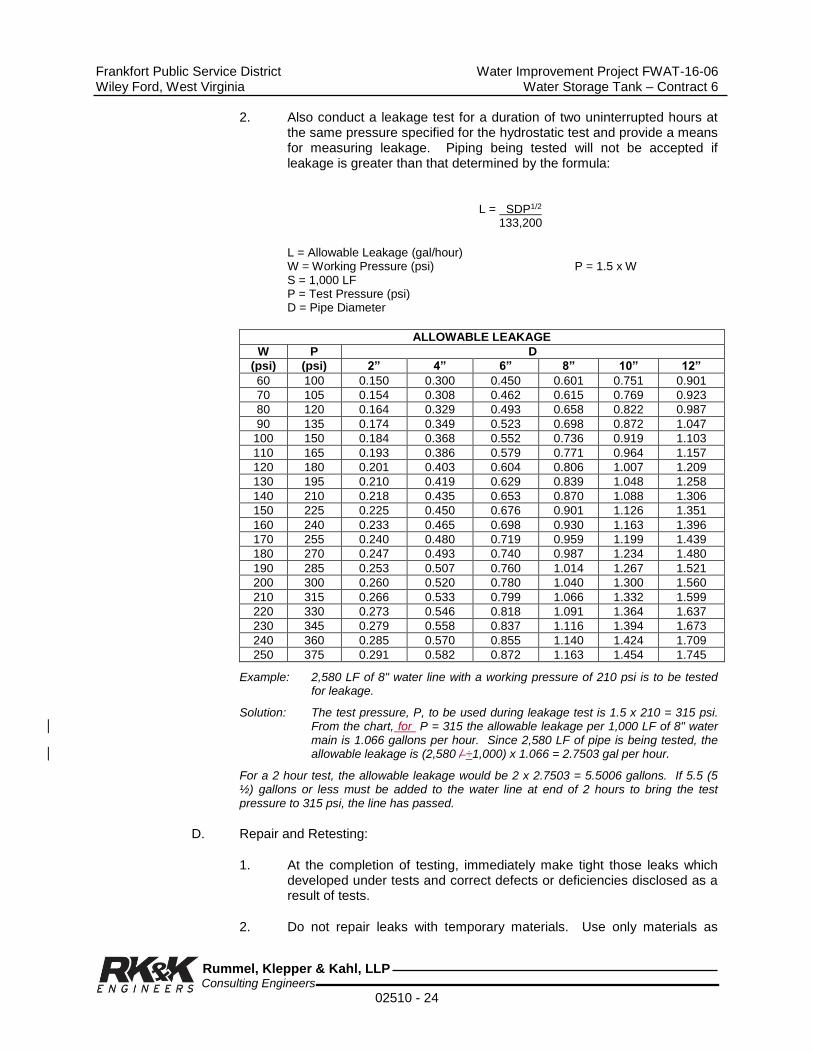
Frankfort Public Service District Water Improvement Project FWAT-16-06 Wiley Ford, West Virginia Water Storage Tank – Contract 6
Rummel, Klepper & Kahl, LLP Consulting Engineers
02510 - 24
2. Also conduct a leakage test for a duration of two uninterrupted hours at the same pressure specified for the hydrostatic test and provide a means for measuring leakage. Piping being tested will not be accepted if leakage is greater than that determined by the formula:
L = SDP1/2
133,200
L = Allowable Leakage (gal/hour) W = Working Pressure (psi) P = 1.5 x W S = 1,000 LF P = Test Pressure (psi) D = Pipe Diameter
ALLOWABLE LEAKAGE
W P D
(psi) (psi) 2” 4” 6” 8” 10” 12”
60 100 0.150 0.300 0.450 0.601 0.751 0.901
70 105 0.154 0.308 0.462 0.615 0.769 0.923
80 120 0.164 0.329 0.493 0.658 0.822 0.987
90 135 0.174 0.349 0.523 0.698 0.872 1.047
100 150 0.184 0.368 0.552 0.736 0.919 1.103
110 165 0.193 0.386 0.579 0.771 0.964 1.157
120 180 0.201 0.403 0.604 0.806 1.007 1.209
130 195 0.210 0.419 0.629 0.839 1.048 1.258
140 210 0.218 0.435 0.653 0.870 1.088 1.306
150 225 0.225 0.450 0.676 0.901 1.126 1.351
160 240 0.233 0.465 0.698 0.930 1.163 1.396
170 255 0.240 0.480 0.719 0.959 1.199 1.439
180 270 0.247 0.493 0.740 0.987 1.234 1.480
190 285 0.253 0.507 0.760 1.014 1.267 1.521
200 300 0.260 0.520 0.780 1.040 1.300 1.560
210 315 0.266 0.533 0.799 1.066 1.332 1.599
220 330 0.273 0.546 0.818 1.091 1.364 1.637
230 345 0.279 0.558 0.837 1.116 1.394 1.673
240 360 0.285 0.570 0.855 1.140 1.424 1.709
250 375 0.291 0.582 0.872 1.163 1.454 1.745
Example: 2,580 LF of 8" water line with a working pressure of 210 psi is to be tested for leakage.
Solution: The test pressure, P, to be used during leakage test is 1.5 x 210 = 315 psi. From the chart, for P = 315 the allowable leakage per 1,000 LF of 8" water main is 1.066 gallons per hour. Since 2,580 LF of pipe is being tested, the allowable leakage is (2,580 / ÷1,000) x 1.066 = 2.7503 gal per hour.
For a 2 hour test, the allowable leakage would be 2 x 2.7503 = 5.5006 gallons. If 5.5 (5 ½) gallons or less must be added to the water line at end of 2 hours to bring the test pressure to 315 psi, the line has passed.
D. Repair and Retesting:
1. At the completion of testing, immediately make tight those leaks which developed under tests and correct defects or deficiencies disclosed as a result of tests.
2. Do not repair leaks with temporary materials. Use only materials as
Frankfort Public Service District Water Improvement Project FWAT-16-06 Wiley Ford, West Virginia Water Storage Tank – Contract 6
Rummel, Klepper & Kahl, LLP Consulting Engineers
02510 - 25
specified for joint making.
3. Repeat tests until test requirements are fully complied with.
E. Disinfection of Water Mains:
1. Before being placed in service, all water pipe installed under this Contract will be disinfected by chlorination.
2. Disinfection of water mains shall be in accordance with AWWA Standard C 651, Disinfecting Water Mains, latest edition.
3. Prior to initiating disinfection operations, the Contractor shall submit to the Engineer for approval a detailed procedure and schedule of the disinfection program to be implemented. The Contractors program shall also describe the proposed method of disposal of water used in the disinfection procedure.
END OF SECTION
Frankfort Public Service District Water Improvement Project FWAT-16-06 Wiley Ford, West Virginia Water Storage Tank – Contract 6
Rummel, Klepper & Kahl, LLP Consulting Engineers
02510 - 26
THIS PAGE LEFT BLANK

Frankfort Public Service District Water Improvement Project FWAT-16-06 Wiley Ford, West Virginia Water Storage Tank – Contract 6
Rummel, Klepper & Kahl, LLP Consulting Engineers
02512 - 1
SECTION 02512
SITE PIPING
PART 1 - GENERAL
1.01 DESCRIPTION
Work performed under this section includes but is not limited to furnishing and installing all outside water piping, drain piping, effluent piping, valves, culverts, fittings, vaults and appurtenances necessary for the complete and satisfactory installation of the outside piping as shown and as specified.
1.02 Standard Specifications
Comply with the Standard Specifications except as modified herein.
PART 2 - MATERIALS
2.01 WATER, RAW WATER, EFFLUENT AND DRAIN PIPING
Water, effluent and drain line piping shall be Class 50 mechanical or slip-on joint ductile iron pipe and fittings conforming to standard specifications.
2.02 PROCESS WATER
Process water pipe shall be seamless copper service type suitable for underground service. Pipe shall be type K in accordance with Standard Specifications.
2.03 WATER METER AND TOTALIZER
This section omitted
2.04 ELECTRICAL CONDUIT
Electrical conduit shall be direct burial DB60 or Schedule 40 meeting requirements of ASTM F512.
2.05 VALVES
A. Gate valves shall meet or exceed AWWA C509. Valves in vaults shall have flange ends and hand-wheel operators. Underground valves shall have mechanical joint ends. Gate valves shall be ductile iron, 250 psi, AFC-2500, or approved equal.
B. Check valves shall be flanged iron body, bronze mounted, full opening swing type in accordance with AWWA standard C-508. Valve shall be style 50 Line as manufactured by American Darling. High service pumps to have check valves with weighted lever.
C. Provide an AWWA extension tee wrench suitable for valve operation. Wrench handle shall extend 4 feet above finish grade.
Frankfort Public Service District Water Improvement Project FWAT-16-06 Wiley Ford, West Virginia Water Storage Tank – Contract 6
Rummel, Klepper & Kahl, LLP Consulting Engineers
02512 - 2
2.06 VALVE BOX
Valve box shall be adjustable screw type with drop lid marked water or sewer appropriately. Valve box shall be as manufactured by Tyler Pipe or equal.
2.07 VAULTS
A. Vaults shall be precast concrete vaults as specified in Section 03400.
B. Vault piping and fittings shall be as specified in Section 02510.
C. Waterproofing shall be as specified in Section 07100.
2.08 METALLIC DETECTION TAPE - WATER
Metallic detection tape shall be 0.004 inch thick by 6 inches wide, blue metallic core type with "CAUTION - BURIED WATER BELOW" message. Metallic detection tape shall be as manufactured by Allen Systems, or equal.
PART 3 - CONSTRUCTION
3.01 PIPING
A. No pipework shall be started until all materials, layout schedules, stakeout and cut sheets have been approved by the Engineer in writing.
B. Proper and suitable tools and equipment for the safe and convenient handling and laying of the pipe and fittings shall be used in accordance with manufacturer's standards. Pipe and fittings shall be carefully handled and lowered into the trench.
C. Whenever a pipe requires cutting to fit in the line or to bring it to the required location, the work shall be done without extra compensation, in a satisfactory manner so as to leave a smooth end perpendicular to the axis of the pipe. The cut end shall be beveled or tapered for push on or mechanical joints.
D. All laying, jointing, testing for defects and for leakage and disinfection shall be performed in the presence of the Engineer. All defects in workmanship rejected by the Engineer shall be promptly corrected by the Contractor and defective material removed from the project.
E. No wedging or blocking will be permitted in laying any pipe unless by written order from the Engineer.
F. All open ends of pipe lines to be abandoned shall have their openings plugged with a two (2) foot minimum thickness of concrete.
G. The Contractor shall verify the location and inverts of all existing utilities at the various points of connection and/or crossing prior to starting any work. Any discrepancies in locations or inverts shall be brought to the attention of the Engineer in order that the designs may be adjusted accordingly. Damages suffered or additional costs incurred by the Contractor as a result of his failure to conform to the requirements of this paragraph shall be the sole responsibility of the Contractor.
Frankfort Public Service District Water Improvement Project FWAT-16-06 Wiley Ford, West Virginia Water Storage Tank – Contract 6
Rummel, Klepper & Kahl, LLP Consulting Engineers
02512 - 3
H. Connections to existing utilities shall be made by the Contractor at such time and in a manner as the Engineer may direct, and the cost shall be borne by the Contractor. No valve, switch, hydrant or other control on existing utility system shall be operated for any purpose by the Contractor without written approval of the Engineer and the utility. All customers affected by such operations shall be notified before the operation and advised of the probable time and length of service disruption.
I. The Contractor shall provide whatever materials, equipment, labor and construction methods, including the making of templates of the existing pipe that are necessary to ensure a watertight connection to existing pipe lines.
J. Roadway valve boxes shall be installed over all buried valves and curb valves.
K. Fire hydrants shall be installed in accordance with the Standard Specifications.
L. Piping systems shall be tested and disinfected in accordance with Section 15950.
M. Metallic detection tape shall be installed over plastic piping or conduit in accordance with the manufacturer's recommended installation instructions.
END OF SESSION
Frankfort Public Service District Water Improvement Project FWAT-16-06 Wiley Ford, West Virginia Water Storage Tank – Contract 6
Rummel, Klepper & Kahl, LLP Consulting Engineers
02512 - 4
THIS PAGE LEFT BLANK

Frankfort Public Service District Water Improvement Project FWAT-16-06 Wiley Ford, West Virginia Water Storage Tank – Contract 6
Rummel, Klepper & Kahl, LLP Consulting Engineers
02535 - 1
SECTION 02535
PIPE AND PIPE FITTINGS
PART 1 - GENERAL
1.01 DESCRIPTION
A. The work of this section includes, but is not limited to
1. Gravity Flow Piping
2. Pressure Flow Piping
B. Related work specified elsewhere
1. Section 02315 - Trenching, Backfilling and Compacting
2. Section 02610 - Site Drainage
3. Section 15080 - Valves and Piping Specialties
4. Section 15950 – Adjusting Balancing Gravity Pipe-Flow Pressure Testing
C. Applicable Standard Details
1. R.C.P Load Table
2. Pipe Bedding Details
3. Concrete Cradle and Encasement Detail
4. Thrust Block for Vertical Bends
5. Thrust Block for Bends, Tees and Caps
D. Pipe and pipe fitting products used for each service shall be as shown on the scheduled included in this Section.
1.02 QUALITY ASSURANCE
A. Install piping to meet the requirements of state and local building codes.
B. Materials contaminated with gasoline, lubricating oil, liquid or gaseous fuels, aromatic compounds, paint solvent, paint thinner, or acid solder will be rejected.
1.03 SUBMITTALS
A. Submit in accordance with Section 01300.
B. Shop Drawings and Product Data: Submit shop drawings and manufacturer’s catalog information for pipe materials, including but not limited to:
1. Piping layout

Frankfort Public Service District Water Improvement Project FWAT-16-06 Wiley Ford, West Virginia Water Storage Tank – Contract 6
Rummel, Klepper & Kahl, LLP Consulting Engineers
02535 - 2
2. Pipe hangers, supports, guides and anchors
3. Pipe wall sleeves and seals
4. Pipe coupling adapters
C. Ductile Iron Pipe
1. Where restrained joints are utilized in lieu of thrust blocking, submit restrained joint calculations in conformance with DIPRA Standards establishing lengths of restrained joint piping required.
2. Submit restrained joint details and materials being utilized.
3. Submit layout drawings showing piece numbers and locations. Also, indicate restrained joint locations.
D. Manufacturer’s Instructions: Submit manufacturer’s instructions for installation of adapters and assembly of mechanical and push-on joints, including the manufacturer’s maximum recommended deflection per joint.
E. Certificates: Submit certification from each product manufacturer attesting that the pipe, pipe fittings, joints, joint gaskets and lubricants meet or exceed specification requirements.
1.04 PRODUCT DELIVERY, STORAGE AND HANDLING
A. During loading, transporting, unloading, and storage on site, exercise care to prevent damage to piping materials.
B. Do not drop pipe or fittings.
C. Store materials on site in enclosures or under protective coverings.
D. Assure that materials are kept clean and dry; do not store materials directly on the ground.
PART 2 - PRODUCTS
2.01 DUCTILE IRON PIPE
A. Pipe, ANSI/AWWA C151/A21.50; standard cement mortar lining, ANSI/AWWA C104/A21.4, outside coated.
1. Pipe -3" to 12": Pressure Class - 350 psi
2. Pipe - 14": Pressure Class - 250 psi
3. Pipe - 16": Pressure Class - 250 psi
B. Ductile Iron Fittings
1. ANSI/AWWA C110/A21.10; with pressure rating equal to pressure ratings of pipe.
2. Fittings to be cement mortar lined and outside coated as for ductile iron pipe.

Frankfort Public Service District Water Improvement Project FWAT-16-06 Wiley Ford, West Virginia Water Storage Tank – Contract 6
Rummel, Klepper & Kahl, LLP Consulting Engineers
02535 - 3
C. Joints
1. Interior piping: Flanged, ANSI/AWWA C110/A21.10.
2. Yard piping: Mechanical joint or push-on joint, ANSI/AWWA C111/A21.11.
2.02 STEEL PROCESS PIPE
A. Pipe
1. ASTM A134, straight seam, electric fusion arc-welded. (pipe larger than 16").
2. ASTM A135, electric resistance welded pipe, Grade (A) (B). *Grade A (Flanging and Bending) (pipe size 2" - 30").
3. ASTM A139, electric fusion (arc) welded steel pipe, Grade B. (size 4" and over).
B. Fittings
1. ASTM A105, forging, carbon steel, for piping components.
2. ASTM A 181, forgings, carbon steel, for general purpose piping, Class 70.
C. Shop Coatings - Pipe, Fittings and Flanges: Minimum SSPC-SP6 with SSPC-Paint 20, type II, organic zinc-rich primer.
2.03 BLACK AND GALVANIZED STEEL PIPE (GENERAL USE)
A. Pipe: ASTM A53, Seamless. Schedule 40, unless otherwise indicated on the contract drawings.
B. Fittings
1. Threaded: Malleable Iron, ANSI B16.3, 150# Class
2. Flanged: Cast Iron, ANSI B16.1, 125# Class
3. Socket Welded: Forged Steel, ANSI B16.11.
C. Flanges: AWWA C 207.
D. Unions: Threaded, Forged Carbon Steel, MSS SP-83.
2.04 COPPER PIPE
A. Pipe: ASTM B42, Seamless, Regular Weight, Temper H80
1. H80 - Hard Drawn, 1/8" - 2" dia.
B. Tubing: ASTM B88, Seamless, Temper H, Type K

Frankfort Public Service District Water Improvement Project FWAT-16-06 Wiley Ford, West Virginia Water Storage Tank – Contract 6
Rummel, Klepper & Kahl, LLP Consulting Engineers
02535 - 4
C. Fittings
1. Wrought Copper and Bronze, Solder Joint: ANSI B16.22
2. Cast Bronze, Solder Joint, Pressure: ANSI B16.18
3. Cast Bronze, Threaded: ANSI B16.15, 125# Class
4. Bronze Flanges/Flange Fittings ANSI B16.24, 150# Class
5. Cast Bronze, for Flared Copper Tube: ANSI B16.26
D. Brazing Filler Material: AWS 5.8.
E. Brazing Flux: Federal Specification O-F-499, Type B.
F. Soldering Flux: Federal Specification O-F-506, Type I.
G. Joints in copper tubing or pipe shall be made using 95-5 tin-antimony solder conforming to ASTM B32.
2.05 POLYVINYL CHLORIDE (PVC) PROCESS PIPE (12" NOMINAL PIPE SIZE AND SMALLER)
A. ASTM D2241, PVC 1120 (12454-B) or PVC 1220 (12454-C) or PVC 2120 (14333-D); SDR- 26, 160 psi.
B. ASTM D1785, Schedule 80, with fittings conforming to ASTM D2467
C. AWWA C900, Class 12454-A or 12454-B; DR 18, 150 psi; with C.I./I.P.S. equivalent outside diameter.
D. Push-on Joints Using Flexible Elastromeric Seals: ASTM D3139
E. Elastromeric Seals (Gaskets) : ASTM F477
2.06 POLYVINYL CHLORIDE (PVC) PROCESS PIPE (LARGER THAN 12" NOMINAL PIPE SIZE)
A. Gravity Sewer Pipe and Fittings
1. Pipe 15" Diameter and Smaller: ASTM D3034, SDR-35.
2. Pipe 18" to 27" Diameter: ASTM F679, SDR-35
3. Flexible Elastomeric Seals: ASTM D3212
4. Seal Material: ASTM F477
2.07 POLYETHYLENE (PE) PROCESS PIPE
A. Pipe: ASTM D1248, Type III, Category 5, Class C, PE3408 SDR 11 or as shown on plans.
B. Fittings: ASTM D3261, PE3408 SDR 11, Butt Heat Fusion Polyethylene Plastic Fittings.

Frankfort Public Service District Water Improvement Project FWAT-16-06 Wiley Ford, West Virginia Water Storage Tank – Contract 6
Rummel, Klepper & Kahl, LLP Consulting Engineers
02535 - 5
2.08 CAST IRON SOIL PIPE
A. Pipe and Fittings: ASTM A74, Service Class. Hub and Spigot or Double-Hub.
B. Joints: Lead Caulked or Double-Seal Compression Gaskets
1. Gaskets: ASTM C564
2. Jute Packing: Federal Specification HH-P-117, Type II
3. Lead: Federal Specification QQ-C-40, Type 1
2.09 PIPE ACCESSORIES
A. Wall Sleeves and Wall Pipes
1. Cast Iron: ASTM A48, Class 30B
2. Ductile Iron: ASTM A536, Grade 60-40-18
3. Mechanical Joint, ANSI/AWWA C111/A21.11
4. Integral cast intermediate wall collar
B. Wall Seals
1. Assembly of synthetic rubber links connected with corrosion resistant bolts; when the bolts are tightened, Delrin plastic pressure plates compress the rubber links to fill the annular space between the pipe and the wall sleeve to form a watertight seal.
2. All wall seals located in penetrations through new walls that are below grade shall be installed in a cast iron wall sleeve that conforms to the requirements of this specification section or installed in a steel wall sleeve. This steel wall sleeve shall consist of a piece of standard weight steel pipe with an integral steel anchoring collar. This anchoring collar shall be 1/4" thick, shall project 3" beyond the pipe outer wall and shall be welded to the pipe around its entire periphery. No sleeves are required if hole is core drilled through a new or existing concrete wall.
C. Flange Adapters
1. For connecting plain-end pipe to flanged valves, fittings and pumps, constructed of ductile iron with 125 lb. flange drilling; anchor to plain-end pipe by means of setscrews conforming to ANSI B16.1. Provide with Buna-N gasket. Temperature range -20oF to 150oF; working pressure as follows:
a. 2" to 12" - 175 psi
b. 14" to 24" - 150 psi
2. Setscrews shall prevent pullout up to working pressure specified plus 100 psi surge pressure.

Frankfort Public Service District Water Improvement Project FWAT-16-06 Wiley Ford, West Virginia Water Storage Tank – Contract 6
Rummel, Klepper & Kahl, LLP Consulting Engineers
02535 - 6
D. Flange Coupling Adapters
1. For joining plain-end pipe to flanged valves, fittings and pumps.
2. Mechanical Joint, ANSI/AWWA C111/A21.11. Provide all flanged coupling adapters with anchor studs.
E. Coupling Adapters
1. Factory pre-assembled couplings for plain-end pipe.
2. Double-ring, steel followers, rubber compounded wedge-gasketed, steel flared middle ring type mechanical joint, ANSI/AWWA C111/A21.11.
F. Transition Couplings
1. To connect pipes of different outside diameters.
2. High-grade steel middle ring with ductile iron follower flanges with rubber compounded wedge section gaskets. Mechanical Joint, ANSI/AWWA C111/A21.11.
2.10 DETECTABLE UNDERGROUND UTILITY MARKING TAPE
A. Tape shall consist of a minimum 5-mil (0.005") overall thickness, with no less than a 35 gauge (0.00035") solid aluminum foil core. The foil must be visible from BOTH sides. The layers shall be laminated together with the extrusion lamination process, not adhesives. Further, there shall be NO inks or printing extending to the edges of the tape. The adhesive will NOT contain any dilutants, pigments or contaminants and is specially formulated to resist degradation by elements normally encountered in the soil. All printing shall be encased to avoid ink rub-off.
B. Test Data:
Property
Method
Value
Thickness
ASTM D2103
5.0 mils
Tensile strength
ASTM D 882
25 lbs/inch (5500 psi)
Elongation
ASTM D 882-88
<50% at break
Printability
ASTM D 2578
>50 dynes/cm2
Flexibility
ASTM D 671-81
Pliable hand
Inks
Mfg. specs.
Heat set Mylex
Message repeat
Mfg. specs.
Every 20"
Foil
Mfg. specs.
Dead soft/annealed
Top layer
Mfg. specs.
Virgin PET
Bottom layer
Mfg. specs.
Virgin LDPE
Adhesives
Mfg. specs.
>30%, solid 1.5#/R

Frankfort Public Service District Water Improvement Project FWAT-16-06 Wiley Ford, West Virginia Water Storage Tank – Contract 6
Rummel, Klepper & Kahl, LLP Consulting Engineers
02535 - 7
Bond strength Boiling H2O @ 100oC 5 hours w/o peel Colors
APWA code
See below
C. Color code shall be as follows:
1. Safety Red: Electric power, distribution and transmission and municipal electric systems.
2. High Visibility Safety Yellow: Gas and oil distribution and transmission, dangerous materials, product and steam.
3. Safety Alert Orange: Telephone and telegraph systems, police and fire communications, and cable television.
4. Safety Precaution Blue: Water systems and slurry pipelines.
5. Safety Green: Sanitary and storm sewer systems.
6. Safety Brown: Force mains, reclaimed water lines and effluent reuse lines.
7. Alert Purple: Reclaimed non-potable water lines.
PART 3 - EXECUTION
3.01 PREPARATION
A. Perform trench excavation to the line and grade indicated on the Contract Drawings and as specified in Section 02221, TRENCHING, BACKFILLING AND COMPACTING.
B. Unless otherwise indicated on the Drawings, provide a minimum cover of 3'-0" above the top of piping laid in trenches.
C. Provide pipe bedding as specified in Section 02315 for each type of pipe used.
D. Provide bedding for all PVC and other plastic pipe or shown on drawings or approved by Engineer. Place aggregate in a manner to avoid segregation, and compact to the maximum practical density so that the pipe can be laid to the required tolerances.
3.02 LAYING PIPE IN TRENCHES
A. Give ample notice to the Engineer in advance of pipe laying operations.
B. Use laser alignment equipment during pipe laying operations.
C. Lower pipe to trench using handling equipment designed for the purpose to assure safety of personnel and to avoid damage to the pipe; do not drop pipe.
D. Lay pipe proceeding upgrade with the bell or groove pointing upstream.
E. Lay to a uniform line with the barrel of the pipe resting solidly in bedding material throughout its length; excavate recesses in bedding material to accommodate joints, fittings and appurtenances; do not subject pipe to a blow or shock to achieve solid bedding or grade.

Frankfort Public Service District Water Improvement Project FWAT-16-06 Wiley Ford, West Virginia Water Storage Tank – Contract 6
Rummel, Klepper & Kahl, LLP Consulting Engineers
02535 - 8
F. Lay each section of pipe in such a manner as to form a close concentric joint with the adjoining section and to avoid offsets in the flow line.
G. Pipe Joining
1. Clean and inspect each pipe and fitting before joining; assemble to provide tight, flexible joints that permit movement caused by expansion, contraction and ground movement.
2. Use lubricant recommended by the pipe or fitting manufacturer for making joints.
3. If unusual joining resistance is encountered or if the pipe cannot be fully inserted into the bell, disassemble joint, inspect for damage, re-clean joint components, and reassemble joint.
H. Assemble mechanical joints in accordance with ANSI/AWWA C111/A21.11, Appendix A; if satisfactory seating of the joint is not obtained at maximum torque, disassemble the joint, re-clean, and reassemble using a new gasket.
I. Push-On Joints
1. Assemble push-on joints in accordance with the recommendations of the pipe manufacturer.
2. On field-cut pipe, file or grind the spigot to resemble the pipe as manufactured so that the spigot end will slip into the socket intact without hindrance or cause gasket damage.
3. Install spigot end to full depth of socket.
4. Prior to installation, mark the spigot end of field-cut pipe with the insertion depth.
J. Check each pipe installed as to line and grade in place; correct deviation from grade immediately; deviation from the required designed grade and alignment will be cause for rejection.
K. Do not deflect joints in pressure piping more than the maximum recommended by the pipe manufacturer.
L. Place sufficient backfill on each section of pipe, as it is laid, to hold pipe firmly in place.
M. Clean the interior of the pipe as the work progresses; where cleaning after laying is difficult because of small pipe size, use a suitable swab or drag in the pipe and pull forward past each joint immediately after joining has been completed.
N. Keep trenches and excavations free of water during construction.
O. When the work is not in progress, and at the end of each workday, securely plug ends of pipe and fittings to prevent trench water, earth or other substances from entering the pipe or fittings.
Frankfort Public Service District Water Improvement Project FWAT-16-06 Wiley Ford, West Virginia Water Storage Tank – Contract 6
Rummel, Klepper & Kahl, LLP Consulting Engineers
02535 - 9
3.03 THRUST RESTRAINT
Provide pressure pipeline and restrained joints or concrete thrust blocking at all bends, tees, and changes in direction; construction concrete thrust blocking in accordance with Standard Details. If restrained joints are utilized, submit design calculations showing determination of restrained lengths and submit joint restraint details. Method of joint restraint shall utilize devices specifically designed for the application for which manufacturer’s data is available for the application. Submit manufacturer’s literature for approval.
3.04 CRADLES AND ENCASEMENT
Provide concrete cradle and encasement for pipeline where approved by Engineer; construct in accordance with Standard Detail.
3.05 BACKFILLING TRENCHES
A. Backfill pipeline trenches only after examination of pipe laying by the Engineer.
B. Backfill trenches as specified in Section 02221, Trenching, Backfilling and Compacting.
C. Install detectable utility marking tape above all plastic pressure pipeline, 12" to 18" below final grade.
3.06 INTERIOR PROCESS PIPING INSTALLATION
A. Pipe Layout in Building
1. Coordinate work to prevent interference between architectural, structural, electrical and mechanical features; the Contract Drawings are generally diagrammatic due to their small scale.
2. Provide such offsets, fittings and other items as may be required to suit conditions.
3. Do not place joints or fittings over switchboards, panels, motors or other electrical equipment.
4. The completed installation shall present a neat, orderly appearance; do not block openings or passageways; run piping parallel to the walls of buildings or structures.
5. Provide clearance between piping, walls, floors, machinery and equipment to prevent the transmission of noise and vibration.
6. Orient handwheels, levers, valve operators and other valve actuators for convenience of operation; set gate valves with the stem above the horizontal.
7. Cut pipe to measurements established at the site and install without springing or forcing; make changes in direction with fittings.
8. Connect ferrous piping to non-ferrous piping with dielectric couplings.

Frankfort Public Service District Water Improvement Project FWAT-16-06 Wiley Ford, West Virginia Water Storage Tank – Contract 6
Rummel, Klepper & Kahl, LLP Consulting Engineers
02535 - 10
B. Equipment Connections
1. Make connections to pumps and other equipment in a manner to eliminate strains on piping and equipment.
2. Install unions or flanges adjacent to equipment and wherever their use will facilitate removal of equipment.
C. Wall Sleeves and Wall Pipes
1. Provide pipes passing through concrete construction with wall sleeves or wall pipes having an integral cast or welded intermediate wall collar, as indicated on the contract drawings.
2. Set wall sleeves and wall pipes of the required size during construction of the wall, foundation or slab.
D. Wall Seals
1. Provide watertight wall seals between pipe and wall sleeve where pipes penetrate building walls, foundations or slabs.
2. Annular space between pipe and wall sleeve shall be sealed with mechanical seal consisting of interlocking synthetic rubber links shaped to fill the space and assembled with bolts and a pressure plate under each bolt head and nut, and when squeezed the rubber links shall form a watertight seal with the pipe sleeve.
E. Flanged Joints
1. Tighten flange bolts so that the gasket is uniformly compressed and sealed; do not distort flanges; do not exceed manufacturer’s recommended maximum torque.
2. Leave flange bolts with ends projected 1/8" to 1/4" beyond the face of the nut after tightening.
F. Flange Adapters and Flange Coupling Adapters
1. Flange Adapters: Tighten flange adapter setscrew with torque wrench to manufacturer’s recommended tightening torque.
2. Flange Coupling Adapters: Drill hole in plain-end of process pipe at each anchor stud location. Tighten anchor stud fully so that anchor stud protrudes into drilled hole, thereby preventing lateral movement of the pipe.
G. Threaded Joints: ANSI B2.1, NPT
Cut threads full and clean with sharp dies; ream ends of pipe after threading and before assembly to remove burrs; leave not more than three pipe threads exposed at each connection; use joint compound or thread tape on the male thread only.

Frankfort Public Service District Water Improvement Project FWAT-16-06 Wiley Ford, West Virginia Water Storage Tank – Contract 6
Rummel, Klepper & Kahl, LLP Consulting Engineers
02535 - 11
H. Solder Joints
1. Ream or file pipe to remove burrs; clean and polish contact surfaces of joints.
2. Apply flux to both male and female end; insert end of tube into fittings full depth of socket.
3. Bring joint to soldering temperature, in as short a time as possible, forming continuous solder bead around entire circumference of joint.
I. Solvent Cemented Joints (PVC): Make joints in pipe and fittings in accordance with the procedures and techniques in ASTM D2855.
J. Fusion Welded Joints (PE): Make joints in pipe and fittings in accordance with the procedures and techniques in ASTM D2657 or ASTM D3261 as applicable.
3.07 PIPE SUPPORTS
A. Support piping from structural construction using pipe hangers, pipe riser clamps and pipe clamp hangers in conjunction with beam clamps, brackets or other equipment as dictated by structure construction.
B. Trapeze hangers approved by the Engineer may be used where several horizontal pipes run closely parallel; secure pipes on trapeze hangers to prevent sideway motion.
C. Install supports for piping 2-1/2" and greater in diameter in accordance with manufacturers recommendations or specifications contained herein, whichever is more stringent; support piping under 2-1/2" diameter as specified herein.
D. Vertical Piping
1. Secure at sufficiently close intervals to keep pipe in alignment and to support weight of pipe and its contents.
2. Support vertical iron and steel pipe on maximum 5'-0" centers with steel pipe riser clamps.
3. Support vertical copper tubing at no more than 10'-0" spacing, using plastic coated steel pipe riser clamps or pipe clamp hangers at end of runs and at intermediate points as installation dictates.
4. Support vertical plastic pipe at 4'-0" centers, using plastic coated pipe riser clamps or pipe clamp hangers at end of runs and at intermediate points as installation dictates.
E. Horizontal Piping
1. Support at sufficiently close intervals to prevent sagging, thrust restraint, and vibration.
2. Install hangers or supports at ends of runs or branches and at each change of direction or alignment.
Frankfort Public Service District Water Improvement Project FWAT-16-06 Wiley Ford, West Virginia Water Storage Tank – Contract 6
Rummel, Klepper & Kahl, LLP Consulting Engineers
02535 - 12
3. Install steel clevis-type pipe hangers for horizontal iron and steel pipe on maximum 10'-0" centers.
4. Install steel clevis-type pipe hangers for copper tubing on 6'-0" centers for 1-1/4" size and smaller, and on 10'-0" centers for copper tubing larger than 1-1/4" size.
5. Install plastic coated ring-type pipe hangers for horizontal plastic pipe on maximum 4'-0" centers, close to every joint, at ends of each branch, and at each change in direction or elevation; hangers shall not compress, distort, cut or abrade plastic piping and shall permit free movement of the pipe.
F. Pipe Bracing: The Contractor is responsible for properly bracing piping against lateral movement or sway. The Engineer shall review with the Contractor and approve method of bracing of piping at each location prior to Contractor proceeding with the installation of the bracing. Bracing shall be installed at all locations where sway is anticipated and as directed by the Engineer.
3.08 CUTTING AND PATCHING
A. Do not cut and patch existing structures without prior permission from the Engineer.
B. Perform cutting and patching where indicated in the contract drawings. Patch to match adjacent finishes.
3.09 TESTING
Test piping systems as specified in Section 15190.
END OF SECTION

Frankfort Public Service District Water Improvement Project FWAT-16-06 Wiley Ford, West Virginia Water Storage Tank – Contract 6
Rummel, Klepper & Kahl, LLP Consulting Engineers
02610 - 1
SECTION 02610
SITE DRAINAGE
PART 1 - GENERAL
1.01 DESCRIPTION
A. The Work of This Section Includes, But Is Not Limited To
1. Storm Drainage Piping
2. Headwalls and Endwalls
3. Inlets
4. Drainage Channels and Swales
5. Riprap
6. Double Face Concrete Barrier
B. Related Work Specified Elsewhere
1. Section 02300 - Earthwork
2. Section 02315 - Trenching, Backfilling & Compacting
1.02 REFERENCES
A. American Association of State Highway and Transportation Officials (AASHTO)
B. Standard Specifications for Construction and Materials, West Virginia Division of Highways latest edition of Standard Specifications Roads and Bridges, and Supplemental Specifications as of date of bid opening.
1.03 SUBMITTALS
Submit certification attesting that materials meet or exceed the specification requirements.
1.04 PRODUCT DELIVERY, STORAGE AND HANDLING
A. PVC Units
1. Transport the units to the job site. Protect until required for installation.
2. Handle to avoid damage to surfaces, edges and corners of units.

Frankfort Public Service District Water Improvement Project FWAT-16-06 Wiley Ford, West Virginia Water Storage Tank – Contract 6
Rummel, Klepper & Kahl, LLP Consulting Engineers
02610 - 2
PART 2 - PRODUCTS
2.01 STORM DRAIN PIPE
HDPE pipe of the sizes indicated on the Contract Drawings and conforming to West Virginia Division of Highways latest edition of Standard Specifications Roads and Bridges.
2.02 SUBBASE AGGREGATE
Conform to the requirements specified in Section 02315.
2.03 RIPRAP STONE
A. Field stone or rough unhewn quarry stone of approximate rectangular shape, hard and angular, and of such quality that it will not disintegrate on exposure to water or weathering.
B. 9" minimum thickness, measured perpendicular to face, with no face dimension less than the thickness of the stone.
C. Not less than 70% of the individual pieces weighing minimum of 150 lbs.; not more than 10% of the individual pieces weighing less than 100 lbs.
2.04 CONCRETE:
Conform to the requirements specified in Section 03300
2.05 ENDWALLS, HEADWALLS AND INLETS
A. Locations and sizes as indicated on the Contract Drawings.
B. PVC surface drainage inlets shall include the drain basin type as indicated on the contract drawing and referenced within the contract specifications. The ductile iron grates (12” and 15” frames are cast iron) for each of these fittings are to be considered an integral part of the surface drainage inlet and shall be furnished by the same manufacturer.
C. The surface drainage inlets shall be as manufactured by Nyloplast a division of Advanced Drainage Systems, Inc., or prior approved equal.
D. The drain basins required for this contract shall be manufactured from PVC pipe stock, utilizing a thermo-molding process to reform the pipe stock to the specified configuration. The drainage pipe connection stubs shall be manufactured from PVC pipe stock and formed to provide a watertight connection with the specified pipe system. This joint tightness shall conform to ASTM D3212 for joints for drain and sewer plastic pipe using flexible elastomeric seals. The pipe bell spigot shall be joined to the main body of the drain basin or catch basin. The pipe stock used to manufacture the main body and pipe stubs of the surface drainage inlets shall meet the mechanical property requirements for fabricated fittings as described by ASTM D3034, Standard for Sewer PVC Pipe and Fittings; ASTM F1336F, Standard for PVC Gasketed Sewer Fittings.

Frankfort Public Service District Water Improvement Project FWAT-16-06 Wiley Ford, West Virginia Water Storage Tank – Contract 6
Rummel, Klepper & Kahl, LLP Consulting Engineers
02610 - 3
E. The grates furnished for all surface drainage inlets shall be ductile iron grates for sizes 8”, 10”, 12”, 15”, 18”, 24”, and 30” (12” and 15” frames are cast iron) and shall be made specifically for each basin so as to provide a round bottom flange that closely matches the diameter of the surface drainage inlet. Grates for drain basins shall be capable of supporting H-25 wheel loading for heavy-duty traffic or H-10 loading for pedestrian traffic. 12” and 15” grates will be hinged to the frame using pins. Metal used in the manufacture of the castings shall conform to ASTM A536 grade 70-50-05 for ductile iron and ASTM A-48-83 class 30B for 12” and 15” cast iron frames. Grates shall be provided painted black.
F. The drain basin body will be cut at the time of the final grade so as to maintain a one piece, leak proof structure. No brick, stone or concrete block will be used to set the grate to the final grade height.
2.06 DOUBLE FACE CONCRETE BARRIER
Provide temporary precast concrete barrier, double face, where indicated on the Contract Drawings in accordance with West Virginia Division of Highways latest edition of Standard Specifications Roads and Bridges, and Supplemental Specifications latest edition as of date of bid opening.
PART 3 - EXECUTION
3.01 TRENCHING, BEDDING, AND BACKFILL
Conform to the requirements specified in Section 02315.
3.02 PIPE LAYING
A. Clean and inspect pipe before lowering into the trench; start pipe laying at the low end and proceed upgrade, unless otherwise approved by the Engineer; bed the pipe for its full length.
B. Fit corrugated metal pipe connecting bands to the corrugations with bolts drawn tight.
C. Replace broken or otherwise damaged pipe, and keep pipe clean of deposits and debris; piping, as laid, shall be approved by the Engineer before the trench is backfilled.
3.03 CONSTRUCTION
A. Locate inlets and endwalls as indicated on the Contract Drawings; perform excavation as specified in Section 02315.
B. Construct endwalls as indicated on Contract Drawings.
Rub-finish exposed surfaces of headwalls and endwalls to meet the approval of the Engineer.
D. Construct drainage channels and swales to the lines and grades and cross-sections indicated on the Contract Drawings.

Frankfort Public Service District Water Improvement Project FWAT-16-06 Wiley Ford, West Virginia Water Storage Tank – Contract 6
Rummel, Klepper & Kahl, LLP Consulting Engineers
02610 - 4
E. Where riprap slope protection and ditch lining is indicated on the Contract Drawings, construct to the lines and grades indicated and in accordance with West Virginia Division of Highway’s latest edition of Standard Specifications Roads and Bridges, and Supplemental Specifications latest edition as of date of bid opening.
3.04 BACKFILLING
A. Backfill structures only after examination by the Engineer.
B. The backfill material used around the PVC inlets shall be crushed stone or other granular material meeting the requirements of class 1 or 2 material as defined in ASTM D2321. The surface drainage inlets shall be bedded and back-filled uniformly in accordance with ASTM D2321. For H-25 load rated installations, an 8” to 10” thick concrete ring will be poured under the grate and frame as recommended by details provided from the manufacturer.
C. Perform backfilling and compaction as specified in Section 02315.
END OF SECTION
Frankfort Public Service District Water Improvement Project FWAT-16-06 Wiley Ford, West Virginia Water Storage Tank – Contract 6
Rummel, Klepper & Kahl, LLP Consulting Engineers
02740 - 1
SECTION 02740
PAVING AND SURFACING
PART 1 – GENERAL
1.01 RELATED WORK
A. Section 02310 - Site Grading
B. Section 02315 - Trenching, Backfilling and Compaction
1.02 QUALITY ASSURANCE
A. Source Quality Control:
1. Maintain the quality or work by using the products of a qualified hot mix asphalt producer and qualified plant operating workmen.
2. Use products of a bulk producer regularly engaged in production of hot-mix asphalt conforming to the standards referenced herein.
3. Use materials conforming to the following requirements: Contract Specific
a. West Virginia Division of Highways Standard Specifications and all supplements thereto (latest edition as of date of bid opening).
B. Workmen Qualifications:
1. Provide at least one person thoroughly trained and experienced in the skills required who readily understands the design and is completely familiar with the application of hot mix asphalt paving concrete paving work and to direct the performance of said work.
2. For actual finishing of hot mix asphalt surfaces and operation of the equipment, use only personnel thoroughly trained and experienced in the skills required.
1.03 REFERENCES:
A. West Virginia Division of Highways Standard Specifications and all supplements thereto (latest edition as of date of bid opening).
B. American Society for Testing and Materials:
1. ASTM D 698, Moisture Density Relations of Soils and Soil Aggregates Mixtures using 5.5 lb Rammer and 12-inch drop.
2. ASTM D 1556, Density of Soil in Place by the Sand Cone Method.
3. ASTM D 3922, Density of Soil and Soil Aggregate in Place by Nuclear Methods (Shallow Depth).
4. ASTM D 3017, Moisture Content of Soil and Soil Aggregate in Place by Nuclear Methods (Shallow Depth).

Frankfort Public Service District Water Improvement Project FWAT-16-06 Wiley Ford, West Virginia Water Storage Tank – Contract 6
Rummel, Klepper & Kahl, LLP Consulting Engineers
02740 - 2
5. ASTM D 2050-82, Density of Bituminous Concrete in Place by Nuclear Method, Standard Test Method for.
1.04 PROJECT CONDITIONS:
A. Environmental Requirements:
1. Do not install aggregate courses when ambient temperature is below or is expected to fall below freezing.
2. Do not use aggregate containing frost nor place aggregate courses on frozen subgrade.
3. Terminate placement of bituminous concrete surface courses of permanent pavement between November fifteen to thirtieth, and do not resume placement prior to April first to fifteenth, interim days between date limits may be used for placement as determined by the Engineer depending on the weather conditions.
4. Do not place bituminous concrete surface courses of permanent pavement when the ambient temperature is 40 degrees F. or lower; not when the temperature of the pavement, base or binder on which it is to be placed is 40 degrees F. or lower. Adhere to manufacturer’s data on air and surface temperature limits and relative humidity during application and curing of coatings.
5. Spread and compact hot-mixed, hot-laid bituminous mixtures in accordance with the West Virginia Division of Highways and all supplements thereto (latest edition as of date of bid opening).
B. Protection:
1. Protect and maintain cut pavement edges until permanent replacement paving is placed.
2. Protect paved surfaces outside of the pavement removal limits. Repair pavement outside removal limits damaged by construction operations at no additional expense to the Owner.
3. Use such means as necessary to protect and maintain pavement materials before, during, and after installation to protect the installed work and materials of other trades.
4. In the event of damage or failure of the work of this section within the Guarantee Period, immediately make repairs and replacements. Upon failure to perform maintenance or repairs within three days after receiving written notice from the Owner or Engineer, the Owner may perform such maintenance or repairs and deduct the cost thereof from any moneys due to become due the Contractor under the Contract.
5. Assume responsibility for any injury or damage resulting from lack of required maintenance or repairs during the Guarantee Period. Indemnify and save harmless the Owner and Engineer from loss by reason of suit or action at law, based upon occurrence or omission occurring during this period.

Frankfort Public Service District Water Improvement Project FWAT-16-06 Wiley Ford, West Virginia Water Storage Tank – Contract 6
Rummel, Klepper & Kahl, LLP Consulting Engineers
02740 - 3
C. Completion Certificate will not be issued until work of this section is completed.
PART 2 – PRODUCTS
2.01 MATERIALS
A. Sub-base:
1. Graded Aggregate: Material conforming to the following requirements:
a. West Virginia Division of Highways Standard Specifications and all supplements thereto (latest edition as of date of bid opening).
B. Hot Mix Asphalt Materials and Pavements
1. Hot Mix Asphalt Base Course
2. Hot Mix Asphalt Leveling Course
3. Hot Mix Asphalt Surface Course
4. Chip Seal Surface Coarse
5. For the above listed items use materials conforming to West Virginia Division of Highways Standard Specifications and all supplements thereto (latest edition as of date of bid opening).
C. Guide Rail: Traffic Barrier W Beam, conforming to West Virginia Division of Highways Standards Specifications and all supplements thereto (latest edition as of date of bid opening).
D. Cement Concrete
1. For curbs and gutters, Class A conforming to Section 03300 – Cast-in-Place Concrete.
2.02 PAVEMENT MIXES
A. Composition of Mixtures: Hot Mix Asphalt Base Course, surface course, and double chip seal surface treatment mixture composition shall conform to the following requirements:
1. West Virginia Division of Highways Standards Specifications and all supplements thereto (latest edition as of date of bid opening).
PART 3 – EXECUTION
3.01 PREPARATION
A. Subsurface Preparation: Perform roadway grading and finish proof rolling to 95% compaction in accordance with AASHTO T-180 just prior to sub-base installation.

Frankfort Public Service District Water Improvement Project FWAT-16-06 Wiley Ford, West Virginia Water Storage Tank – Contract 6
Rummel, Klepper & Kahl, LLP Consulting Engineers
02740 - 4
B. Pavement Removal:
1. Cut existing pavement to neat lines equidistant from the centerline of the trench.
2. Cut pavement with a mechanical saw.
3. Remove pavement to a width equal to the specified maximum trench width plus two feet and not less than one foot on each side of the trench width as excavated.
4. If pavement is removed or disturbed for a greater width without written authorization of the Engineer, the Owner will require the Contractor to replace such pavement without compensation.
C. Subgrade: Backfill and compact trenches as specified in Section 02221.
D. Perform paving only after site grading, trenching, etc. have been completed, the road properly cleaned by sweeping, and accepted by the Engineer.
E. The moisture content of the subgrade material at the time of compaction shall be not more than five percentage points above or below the optimum moisture content.
F. At joints between existing pavements and new paving work, the edges of existing pavements shall be cut and neatly trimmed as approved by the Engineer. An application of Class AC-20 petroleum asphalt shall be provided at the locations where new bituminous paving joins existing bituminous paving.
G. At the end of overlay section the new pavement shall be “healed in” to the existing pavement.
3.02 INSTALLATION
A. Install graded aggregate sub-base, bituminous concrete base coarse, and bituminous concrete surface coarse to after compaction thickness indicated on drawings in accordance with the following requirements:
1. West Virginia Division of Highways Standard Specifications and all supplements thereto.
B. Trenches are to be fully protected (covered or filled) at the end of each work day.
C. Any backfill and pavement construction within West Virginia Division of Highways right-of-way can be monitored by West Virginia Division of Highways construction personnel.
3.03 MAINTENANCE
A. Maintain without additional compensation, such work of this Section done under this Contract for a period of 12 months after the date of the Owner’s approval of the Completion Certificate issued by the Engineer, including the repair or removal and replacement of such work which has failed or has been damaged or wherever surface depressions have been developed. Materials and methods

Frankfort Public Service District Water Improvement Project FWAT-16-06 Wiley Ford, West Virginia Water Storage Tank – Contract 6
Rummel, Klepper & Kahl, LLP Consulting Engineers
02740 - 5
used to repair or replace such work to conform to the applicable requirements of this Section.
B. Should the Contractor fail to perform required maintenance or repairs within three days after receiving written notice from the Owner or Engineer, the Owner may perform such maintenance or repairs and deduct the cost thereof from any monies due or to become due the Contractor.
END OF SECTION

Frankfort Public Service District Water Improvement Project FWAT-16-06 Wiley Ford, West Virginia Water Storage Tank – Contract 6
Rummel, Klepper & Kahl, LLP Consulting Engineers
02740 - 6
THIS PAGE LEFT BLANK
Frankfort Public Service District Water Improvement Project FWAT-16-06 Wiley Ford, West Virginia Water Storage Tank – Contract 6
Rummel, Klepper & Kahl, LLP Consulting Engineers
02820 - 1
SECTION 02820
CHAIN LINK FENCE AND GATES
PART 1 - GENERAL
1.01 DESCRIPTION
Work performed under this section shall include, but is not limited to, furnishing and installing chain link fencing, gates, and accessories necessary for the complete and satisfactory installation of chain link fence systems as shown and as specified.
1.02 REFERENCES
A. ASTM A121 Specification for Metallic-Coated Carbon Steel Barbed Wire
B. ASTM A392 Specification for Zinc-Coated Steel Chain-Link Fence Fabric
C. ASTM A491 Specification for Aluminum-Coated Chain-Link Fabric
D. ASTM A780 Standard Practice for Repair of Damaged and Uncoated Areas of Hot Dip Galvanized Coatings
E. ASTM A817 Specification for Metallic-Coated Steel Wire for Chain Link Fence Fabric and Marcelled Tension Wire
F. ASTM A824 Specification for Metallic-Coated Steel Marcelled Tension Wire for Use with Chain Link
G. ASTM F552 Standard Terminology Relating to Chain Link Fencing
H. ASTM F567 Standard Practice for Installation of Chain Link Fence
I. ASTM F626 Specification for Fence Fittings
J. ASTM F900 Specification for Industrial and Commercial Swing Gates
M. ASTM F1043 Specification for Strength and Protective Coatings of Metal Industrial Fence Framework
N. ASTM F1184 Specification for Industrial and Commercial Horizontal Slide Gates
O. ASTM F1345 Specification for Zinc-5% Aluminum-Mischmetal Alloy-Coated Steel Chain-Link Fence Fabric
T. ASTM F2200 Specification for Automated Vehicular Gate Construction
U. ASTM F2611 Guide for Design and Construction of Chain Link Security Fencing
V. Chain Link Manufacturers Institute
W NFPA 70e Handbook for Electrical Safety in the Workplace
X. UL325 Automatic operators: Door, Drapery, Gate, Louver and Window

Frankfort Public Service District Water Improvement Project FWAT-16-06 Wiley Ford, West Virginia Water Storage Tank – Contract 6
Rummel, Klepper & Kahl, LLP Consulting Engineers
02820 - 2
1.03 SUBMITTALS
Submit the following working drawing information:
A. Cross sectional dimensions of posts, braces, rails, fittings, accessories and gate frames; design of gates; and details of gate hardware.
B. Spacing of posts and location of gates; abrupt changes in grade; and corner,
gate, anchor, end and pull post.
1.04 QUALITY ASSURANCE
A. Manufacturer: Company headquartered in the United States, having U.S. manufacturing facility/facilities specializing in manufacturing chain link fence products experience; comply with Section 01300.
B. Fence contractor: Company with demonstrated successful experience installing similar project and products in accordance with ASTM F567.
C. Tolerances: Current published edition of ASTM specifications tolerances apply. ASTM specification tolerances supersede any conflicting tolerance.
PART 2 – PRODUCTS
2.01 STEEL CHAIN LINK FABRIC
A. Zinc-Coated Steel Fabric: ASTM A392 hot dipped galvanized before or after weaving.
1. Class 2 – 2.0 oz. /ft²
2.02 ROUND STEEL PIPE FENCE FRAMEWORK
A. Round steel pipe and rail: Round steel pipe and rail to be cold-rolled electric-resistance welded pipe in accordance with ASTM F1043 Materials Design Group IC, minimum steel yield strength 50,000 psi. Type B external coating, hot dip galvanized zinc 1.0 oz./ft² with a clear polymeric overcoat, Type D interior 90% by weight zinc-rich coating having a minimum thickness of .-30 mils. 1. Line post (2-inches O.D.)
2. End, Corner, Pull post (3-inches O.D.)
3. Top rail, brace rail, bottom and intermediate rails, (1 5/8 inches O.D.)
2.03 TENSION WIRE
A. Metallic Coated Steel Marcelled Tension Wire: 7 gauge Marcelled wire complying with ASTM A824
1. Type II Zinc-Coated, ASTM A817 Class 5 – 2.0 oz. /ft²
2.04 BARBED WIRE
A. Metallic Coated Steel Barbed Wire: Comply with ASTM A121, double 12-1/2
Frankfort Public Service District Water Improvement Project FWAT-16-06 Wiley Ford, West Virginia Water Storage Tank – Contract 6
Rummel, Klepper & Kahl, LLP Consulting Engineers
02820 - 3
gauge twisted strand wire, with 4 point 14 gauge round barbs spaced 5 inches on center. Match coating type to that of the chain link fabric. High Security barb spacing is 3” on center.
B. Coating:
1. Coating Type Z – Zinc-coated: Strand wire coating Type Z, Class 3, 0.80 oz./ft², barb coating 0.70 oz./ft²
2.05 FITTINGS
A. Tension and Brace Bans: Galvanized pressed steel complying with ASTM F626, minimum steel thickness of 12 gauge, minimum width of ¾ in. and minimum zinc coating of 1.20 oz./ft².
B. Terminal Post Caps, Line Post Loop Tops, Rail and Brace Ends, Boulevard
Clamps, Rail Sleeves: In compliance to ASTM F626, pressed steel galvanized after fabrication having a minimum zinc coating of 1.20 oz. /ft².
C. Truss Rod Assembly: In compliance with ASTM F626, 3/8 in. diameter steel
truss rod with a pressed steel tightener, minimum zinc coating of 1.2 oz./ft², assembly capable of withstanding a tension of 2,000 lbs.
D. Tension Bars: In compliance with ASTM F626. Galvanized steel one-piece
length (2 in. 50mm) less than the fabric height. Minimum zinc coating 1.2 oz. /ft². (Bars are to be sized in accordance to the size mesh of the chain link)
E. Barbed Wire Arms: In compliance with ASTM F626, pressed steel galvanized
after fabrication, minimum zinc coating of 1.20 oz. /ft², capable of supporting a vertical 250 lb. load.
2.06 TIE WIRE and HOG RINGS
A. Tie Wire and Hog Rings:
1. Aluminum alloy ties and hog rings per ASTM F626. 9 gauge
2.07 SWING GATES Galvanized steel welded fabrication in compliance with ASTM F900. Gate frame
members 1.900 in. OD (48.3 mm). ASTM F1043 Group IC 40 galvanized steel pipe. Frame members spaced no greater than 8 ft. apart vertically and horizontally. Welded joints protected by applying zinc-rich pain in accordance with ASTM Practice A780. Positive locking gate latch, pressed steel galvanized after fabrication. Galvanized malleable iron or heavy gauge pressed steel post and frame hinges. Match gate fabric to that of the fence system. Gateposts, F1043 Group IC galvanized steel pipe (3 inch O.D., 15/ft). Electrically operated gates must comply with ASTM F2200 and UL325.
PART 3 – EXECUTION
3.01 FRAMEWORK INSTALLATION
A. Posts: Posts shall be set plumb in concrete footings in accordance with ASTM F567. Minimum footing depth, 24 in. plus an additional 3 in. for each 1 ft. increase in the fence height over 4 ft. Minimum footing diameter four times the
Frankfort Public Service District Water Improvement Project FWAT-16-06 Wiley Ford, West Virginia Water Storage Tank – Contract 6
Rummel, Klepper & Kahl, LLP Consulting Engineers
02820 - 4
largest cross section of the post up to 4.00” and three times the largest cross section of post 4.00”, and greater. (Site soil conditions, local frost depth, fence height and wind load may require larger diameter or deeper footings). Top of concrete footing to 6 inches below grade to allow for additional surface coating, crowned to shed water away from the post. Line posts installed at intervals not exceeding 10 ft. on center.
B. Top rail: When specified, install 21 ft. lengths of rail continuous thru the line post
or barb arm loop top. Splice rail using top rail sleeves minimum 6 in. long. Rail shall be secured to the terminal post by a brace band and rail end. Bottom rail or intermediate rail shall be field cut and secured to the line posts using boulevard clamps or brace band with rail end. Fences 12 feet high or higher require mid rail.
C. Terminal posts: End, corner, pull and gate posts shall be braced and trussed for
fence 6 ft. and higher and for fences 5 ft. in height not having a top rail. The horizontal brace rail and diagonal truss rod shall be installed in accordance ASTM F567. Truss rod is not required when center rail is used. For fences without top rail an additional brace is required at the top of the chain link between the first line post and the terminal post.
D. Tension wire: Shall be installed 2 in. up from the bottom of the fabric. Fences without top rail shall have a tension wire installed 2 in. down from the top of the fabric. Tension wire to be stretched taut, independently and prior to the fabric, between the terminal posts and secured to the terminal post using a brace band. Secure the tension wire to each line post with a tie wire. Install the top tension wire through the barb arm loop for fences having barbed wire and no top rail.
3.02 CHAIN LINK FABRIC INSTALLATION
Chain Link Fabric: Install fabric to outside of the secured area. Attached fabric to the terminal post by threading the tension bar through the fabric; secure the tension bar to the terminal post with tension bands and 5/16 in. carriage bolts spaced no greater than 12 inches on center. Small mesh fabric less than 1 in., attach to terminal post by sandwiching the mesh between the post and a vertical 2 in. wide by 3/16 in. galvanized steel strap using carriage bolts, bolted thru the bar, mesh and post spaced 15 in. on center. Chain link fabric to be stretched taut free of sag. Fabric to be secured to the line post with tie wires spaced no greater than 12 inches on center and to rail spaced no greater than 18 inches on center. Secure fabric to the tension wire with hog rings spaced no greater than 18 inches apart. Aluminum or steel tie wires shall be wrapped around the post or rail and attached to the fabric wire picket on each side by twisting the tie wire around the fabric wire picket two full turns. Excess wire shall be cut off and bent over to prevent injury. The installed fabric shall have a ground clearance of no more 2 inches or as shown on drawing. Chain link should set on finished surface on tennis courts or rat walls.
3.03 BARBED WIRE INSTALLATION
Barbed Wire: Stretched taut between terminal posts and secured in the slots provided on the line post barb arms. Attach each strand of barbed wire to the terminal post using a brace band.
3.04 GATE INSTALLATION
Frankfort Public Service District Water Improvement Project FWAT-16-06 Wiley Ford, West Virginia Water Storage Tank – Contract 6
Rummel, Klepper & Kahl, LLP Consulting Engineers
02820 - 5
A. Swing Gates: Installation of swing gates and gateposts in compliance with ASTM F567. Direction of swing shall be inward. Gates shall be plumb in the closed position having a bottom clearance of 3 inches in the closed position. Double gate drop bar receivers shall be set in a concrete footing minimum 6 in. diameter 24 in. deep. Gate leaf holdbacks shall be installed for all double gates. Electrically operated gates must be manufactured and installed in compliance with ASTM F2200, UL 325 and NFPA 70e.
3.05 NUTS AND BOLTS
Bolts: Carriage bolts used for fittings shall be installed with the head on the secure side of the fence. All bolts shall be peened over to prevent removal of the nut.
3.06 CLEAN UP
Clean Up: The area of the fence line shall be left neat and free of any debris caused by installation of the fence to the satisfaction of the owner.
END OF SECTION

Frankfort Public Service District Water Improvement Project FWAT-16-06 Wiley Ford, West Virginia Water Storage Tank – Contract 6
Rummel, Klepper & Kahl, LLP Consulting Engineers
02820 - 6
THIS SECTION LEFT BLANK
Frankfort Public Service District Water Improvement Project FWAT-16-06 Wiley Ford, West Virginia Water Storage Tank – Contract 6
Rummel, Klepper & Kahl, LLP Consulting Engineers
03300 - 1
SECTION 03300
CAST-IN-PLACE CONCRETE
PART 1 - GENERAL
1.01 DESCRIPTION
A. The Work of This Section Includes, But Is Not Limited To
1. Concrete Reinforcement
2. Concrete Formwork
3. Concrete accessories.
4. Concrete material
B. Related Work Specified Elsewhere
1. Section 03600 - Grout
1.02 REFERENCED STANDARDS AND SPECIFICATIONS
A. American Concrete Institute (ACI)
1. 117 Standard Specifications for Tolerances for Concrete Construction and Materials
2. 201 Guide for Making a Condition Summary of Concrete In Service
3. 301 Specifications for Structural Concrete for Buildings
4. 304 Recommended Practice for Measuring, Mixing, Transporting, and Placing Concrete
5. 305R Hot Weather Concreting
6. 306R Cold Weather Concreting
7. 309 Recommended Practice for Consolidation of Concrete
8. 315 Manual of Standard Practice for Detailing Reinforcing Concrete Structures
9. 318 Building Code Requirements for Reinforced Concrete
10. 347 Recommended Practice for Concrete Formwork
11. 350R Concrete Sanitary Engineering Structures
B. American Society for Testing and Materials (ASTM)

Frankfort Public Service District Water Improvement Project FWAT-16-06 Wiley Ford, West Virginia Water Storage Tank – Contract 6
Rummel, Klepper & Kahl, LLP Consulting Engineers
03300 - 2
1. A185 Specification for Welded Steel Wire Fabric for Concrete Reinforcement
2. A615 Specification for Deformed and Plain Billet-Steel Bars for Concrete Reinforcement
3. C31 Making and Curing Concrete Test Specimens in the Field
4. C33 Specifications for Concrete Aggregate
5. C39 Test for Compressive Strength of Cylindrical Concrete Specimens
6. C42 Obtaining and Testing Drilled Cores and Sawed Beams of Concrete
7. C94 Specification for Ready-Mixed Concrete
8. C138 Standard Test Method for Density (Unit Weight), Yield, and Air Content (Gravimetric) of Concrete
9. C143 Test for Slump of Portland Cement Concrete
10. C150 Specification for Portland Cement
11. C171 Specification for Sheet Materials for Curing Concrete
12. C172 Sampling Fresh Concrete
13. C173 Test for Air Content of Freshly Mixed Concrete by the Volumetric Method
14. C231 Test for Air Content of Freshly Mixed Concrete by the Pressure Method
15. C260 Specification for Air-Entraining Admixtures for Concrete
16. C309 Specification for Liquid Membrane-forming Compounds for Curing Concrete
17. C494 Specification for Chemical Admixtures for Concrete
18. C881 Specification for Epoxy-Resin-Base Bonding Systems for Concrete
19. D1752 Specification for Preformed Sponge Rubber and Cork Expansion Joint Fillers for Concrete Construction
20. D2103 Standard Specification for Polyethylene Film and Sheeting
21. E154 Standard Test Methods for Water Vapor Retarders used in Contact with Earth Under Concrete Slabs, on Walls, or as Ground Cover.
C. American Welding Society (AWS)

Frankfort Public Service District Water Improvement Project FWAT-16-06 Wiley Ford, West Virginia Water Storage Tank – Contract 6
Rummel, Klepper & Kahl, LLP Consulting Engineers
03300 - 3
1. D12.1 Welding Reinforcing Steel Metal Inserts and Connections in Reinforced Concrete Construction
D. Corps of Engineers
1. CRD C572 Specification for Polyvinyl Chloride Waterstop
2. CRD C621 Specification for Nonshrink Grout
E. American Association Of State Highway and Transportation Officials (AASHTO)
1. M182 Burlap Cloth Made From Jute or Kenaf
F. West Virginia Division of Highways
1. Standard Specifications Roads and Bridges (latest edition as of date of bid).
1.03 QUALITY ASSURANCE
A. Design Criteria
1. Design each required concrete group to meet the physical properties specified in Table I of this Section.
2. In addition to structural strength and stability requirements, design and construct concrete in structures to ensure:
a. Maximum density and impermeability - these quantities are achieved with low water cement ratios and a slow, moist cure.
b. Maximum resistance to reaction of chemicals, alternate wetting and drying, and exposure to the elements.
c. Well-formed and smooth surfaces to minimize resistance to flow.
B. Testing Agency: Concrete testing for slump, compressive strength, and air content shall be performed by a testing laboratory engaged and paid by the Contractor and approved by the Engineer. No concrete shall be poured unless the testing agency is on-site.
C. Concrete Testing:
1. Perform compressive strength, slump, and air content tests for each 50 cubic yards of concrete placed, or any portion thereof, for each structure. Cast at least 5 cylindrical strength test specimens for each batch. Test 2 cylinders at 7 days; test 2 cylinders at 28 days. Hold the remaining cylinder for testing in the event that any of the other cylinders are damaged prior to testing.
2. Determine concrete strength from standard test specimens made and cured according to ASTM C31 and ASTM C172, and tested in accordance with ASTM C39. Perform core drilling and testing in accordance with ASTM C42. Compute and evaluate in accordance with ASTM C94.

Frankfort Public Service District Water Improvement Project FWAT-16-06 Wiley Ford, West Virginia Water Storage Tank – Contract 6
Rummel, Klepper & Kahl, LLP Consulting Engineers
03300 - 4
3. Determine air content in accordance with ASTM C231 or ASTM C173, as applicable.
4. Determine slump in accordance with ASTM C143.
5. Keep a slump cone and an air meter in close proximity to all concrete placements.
1.04 SUBMITTALS
A. Shop Drawings: Submit detailed reinforcing drawings prepared in accordance with ACI 315, including bar schedule with bar marks and bends indicated.
B. Design Mix
1. Prior to start of placing concrete, submit design mix for each group of concrete, indicating that the concrete ingredients and proportions will result in a concrete mix meeting the physical requirements for each concrete group specified in Table II of this Section.
2. Do not vary proportions of the ingredients or source of material of the approved mix without submitting corresponding test result documentation to the Engineer for approval.
C. Certificates
1. Submit a certification attesting that reinforcing steel meets the requirements of ASTM A615 including Supplementary Requirement S1, and that welded steel wire fabric meets the requirements of ASTM A185.
2. Submit, with the concrete mix design, laboratory test reports and manufacturer’s certificates attesting the conformance of ingredients with these specifications (ASTM C94, paragraph 5.3.2).
3. Submit a certification or delivery ticket from the concrete supplier for each batch delivered to the site (ASTM C94, Section 15). The delivery ticket shall list: name of ready-mix batch plant, serial number of ticket, date and truck number, name of contractor, specific designation of job, batch number, amount of concrete, time loaded or of first mixing of cement and aggregates, number of revolutions, water added by receiver of concrete and receivers initials, type and name of admixtures and amount of same, type and brand of cement, amount of cement, total water content by producer, maximum size of aggregate, weights of fine and coarse aggregate, and indication that ingredients are as previously certified or approved.
D. Test Reports: Submit four (4) copies of required slump tests, air content tests, and strength tests.
E. Pour Schedules: Submit concurrently with the steel reinforcing drawings six (6) copies of concrete pour schedules showing sequence of pours and all contraction, expansion and construction joints.

Frankfort Public Service District Water Improvement Project FWAT-16-06 Wiley Ford, West Virginia Water Storage Tank – Contract 6
Rummel, Klepper & Kahl, LLP Consulting Engineers
03300 - 5
1.05 PRODUCT DELIVERY, STORAGE AND HANDLING
A. Reinforcing Steel
1. For reinforcing steel fabricated on-site, ship from the mill in bundles, limited to one size and length, tagged with a waterproof tag showing the name of the mill, heat number, grade and size of the bars, and identifying number.
2. For reinforcing steel fabricated off-site, deliver in bundles identified as to structure and shop drawing number. Identify each individual bar with a waterproof tag showing the grade, size and bar mark from the approved bar schedule.
B. Concrete Ingredients: Handle, control and store concrete materials in accordance with ACI 304, Chapter 2.
PART 2 – PRODUCTS
2.01 FORM MATERIALS
A. Forms for Exposed Finish Concrete: Plywood, metal, metal-framed plywood faced, or other acceptable panel-type materials, to provide continuous, straight, smooth, exposed surfaces. Furnish in largest practicable sizes to minimize number of joints and to conform to joint system shown on drawings.
1. Use plywood complying with US Product Standard PS-1 “B-B (Concrete Form) Plywood”, Class I, Exterior Grade or better, mill-oiled and edge-sealed, with each piece bearing legible inspection trademark.
2. Forms for Unexposed Finish Concrete: Plywood, lumber, metal, or other acceptable material. Provide lumber dressed on at least two edges and one side for tight fit.
3. Form Coatings: Provide commercial formulation form-coating compounds that will not bond with, stain, nor adversely affect concrete surfaces, and will not impair subsequent treatments of concrete surfaces.
4. Form Ties: Factory-fabricated, adjustable-length, removable or snap off metal form ties, designed to prevent form deflection and to prevent spalling concrete upon removal. Provide units that will leave no metal closer than 1-1/2 in. to surface.
5. Provide ties which, when removed, will leave holes not larger than 1 in. diameter in concrete surface.
B. Earth cuts shall not be used as forms for vertical surfaces unless approved by Engineer.
2.02 REINFORCING MATERIALS
A. Reinforcing Bars: ASTM A- 615, Grade 60, deformed.
B. Welded Wire Fabric: ASTM A-185 welded steel wire fabric.
Frankfort Public Service District Water Improvement Project FWAT-16-06 Wiley Ford, West Virginia Water Storage Tank – Contract 6
Rummel, Klepper & Kahl, LLP Consulting Engineers
03300 - 6
C. Supports for Reinforcement: Bolsters, chairs, spacers, and other devices for spacing, supporting, and fastening reinforcing bars and welded wire fabric in place. Use wire bar type supports complying with CRSI specifications.
1. For slabs-on-grade, use supports with sand plates or horizontal runners where base material will not support chair legs.
2. For exposed-to-view concrete surfaces, where legs of supports are in contact with forms, provide supports with legs which are plastic protected (CRSI, Class 1) or stainless steel protected (CRSI, Class 2).
2.03 CONCRETE MATERIALS
A. Portland Cement: ASTM C 150, Type II or Type IIA
1. Use one brand of cement from one manufacturing source and mill throughout project, unless otherwise acceptable to Engineer.
B. Normal Weight Aggregates: ASTM C 33, and as herein specified. Provide aggregates from a single source for exposed concrete.
1. Fine Aggregate shall be clean, sharp, natural or manufactured sand, free from loam, clay lumps, or other deleterious substance within allowable standards.
2. Coarse Aggregate shall be clean, uncoated, graded aggregate, containing no clay, mud, loam or foreign matter and free of excessively flat or elongated pieces.
a. Maximum size of course aggregate shall not exceed:
(1) 1/5 narrowest dimension between forms.
(2) ¾ minimum clear spacing between reinforcing.
(3) 1/3 thickness of slab.
C. Water: Potable
D. Admixtures 1. General: Total Chloride ions from admixtures and other measures shall be no greater than 0.1 percent by weight of cement in the concrete mix immediately prior to service exposure.
2. Admixtures containing calcium chloride or soluble chlorides shall not be used in concrete containing aluminum and or subject to alkali-aggregate reaction.
E. Air-Entraining Admixture: ASTM C 260, certified by manufacturer to be compatible with other required admixtures.
1. Available Products: Subject to compliance with requirements, products that may be incorporated in the work include, but are not limited to, the following:

Frankfort Public Service District Water Improvement Project FWAT-16-06 Wiley Ford, West Virginia Water Storage Tank – Contract 6
Rummel, Klepper & Kahl, LLP Consulting Engineers
03300 - 7
a. “Sika Aer”; Sika Corp.
b. “MB-VR or MB-AE”; Master Builders
c. “Darex AEA” or “Daravair”; W. R. Grace
d. Or Equal
F. Water-Reducing Admixture: ASTM C 494, Type A, and containing not more than 0.1 percent chloride ions.
1. Available Products: Subject to compliance with requirements, products which may be incorporated in the work include, but are not limited to, the following:
a. “WRDA Hycol”; W.R. Grace.
b. “Pozzolith Normal”; Master Builders.
c. “Plastocrete 160”; Sika Chemical Corp.
d. Or Equal
G. High Range Water Reducing Admixture (Super Plasticizer): ASTM C 494, Type F or Type G and containing not more than 0.1 percent chloride ions.
1. Available Products: Subject to compliance with requirements, products which may be incorporated in the work include, but are not limited to, the following:
a. “WRDA 19” or Daracem”; W. R. Grace.
b. “Sikament”; Sika Chemical Corp.
c. “Rheobuild”; Master Builders.
d. Or Equal
H. Water Reducing, Non Chloride Accelerator Admixture: ASTM C 494, Type E, and containing not more than 0.1 percent chloride ions.
1. Available Products: Subject to compliance with requirements, products which may be incorporated in the work include, but are not limited to, the following:
a. “Accelguard 80”; Euclid Chemical Co.
b. “Pozzolith High Early”; Master Builders.
c. “Gilco Accelerator”; Gifford-Hill/ American Admixtures.
d. Or Equal
I. Water Reducing, Retarding Admixture: ASTM C 494, Type D, and containing not more than 0.1 percent chloride ions.

Frankfort Public Service District Water Improvement Project FWAT-16-06 Wiley Ford, West Virginia Water Storage Tank – Contract 6
Rummel, Klepper & Kahl, LLP Consulting Engineers
03300 - 8
1. Available Products: Subject to compliance with requirements, products which may be incorporated in the work include, but are not limited to, the following:
a. “Pozzolith Retarder”; Master Builders.
b. “Eucon Retarder 75”; Euclid Chemical Co.
c. “Daratard”, W. R. Grace.
d. Or Equal
J. Prohibited Admixtures: Calcium chloride thyocyanates or admixtures containing more than 0.1 percent chloride ions are not permitted.
2.04 RELATED MATERIALS
A. Waterstops.
1. Provide flat, dumbbell-type or centerbulb-type waterstops at all construction, contraction and expansion joints and at other joints as indicated on the Contract Drawings or needed.
a. Material: Polyvinyl Chloride: Corps of Engineers CRD-C 572.
b. Provide 9-inch wide by 3/8 in. thick unless noted otherwise on the Contract Drawings.
c. Manufacturers:
(1) Paul Murphy Plastics Company; Wirestop®
(2) W.R. Meadows, Inc.
(3) Greenstreak
(4) Or Equal
2. Adhesive Waterstop.
a. Material: Compounded bentonite and butyl material specifically manufactured for use in cold joints, which swells upon hydration to form a self-healing compression seal.
b. Adhere to cold surface using synthetic rubber/resin based solvent adhesive and concrete cut nails.
c. Minimum section shall be 1 in. x 3/4 in., placed per manufacturer’s instructions.
d. Manufacturers:
(1) Volclay Waterstop-RX by American Colloid Company.
(2) Or Equal.
Frankfort Public Service District Water Improvement Project FWAT-16-06 Wiley Ford, West Virginia Water Storage Tank – Contract 6
Rummel, Klepper & Kahl, LLP Consulting Engineers
03300 - 9
B. Vapor Retarder: Provide vapor retarder cover over prepared base material where indicated below slabs on grade. Use only materials, which are resistant to decay when tested in accordance with ASTM E 154, as follows:
1. ASTM D2103, Polyethylene sheet not less than 8 mils thick.
C. Absorptive Cover: Burlap cloth made from jute or kenaf, weighing approximately 9 oz. per square yard, complying with AASHTO M 182, Class 2.
D. Moisture Retaining Cover: One of the following, complying with ASTM C 171.
1. Polyethylene film.
E. Liquid Membrane Forming Curing Compound: Liquid type membrane forming curing compound complying with ASTM C 309, Type I, Class A. Moisture loss not more than 0.055 gr./sq. cm. when applied at 200 sq. ft./gal.
1. Available Products: Subject to compliance with requirements, products which may be incorporated in the work include, but are not limited to, the following:
a. “Masterseal”; Master Builders.
b. “Ecocure”; Euclid Chemical Co.
c. “Spartan-Cote”; The Burke Co.
d. Or Equal
G. Bonding Compound: Polyvinyl acetate or acrylic base.
1. Available Products: Subject to compliance with requirements, products which may be incorporated in the work include, but are not limited to, the following:
2. Acrylic or Styrene Butadiene:
a. “Acrylic Bondcrete”; The Burke Co.
b. “SBR Latex”; Euclid Chemical Co.
c. “Daraweld C”; W. R. Grace.
d. Or Equal
H. Epoxy Adhesive: ASTM C 881, two-component material suitable for use on dry or damp surfaces. Provide material “Type”, “Grade”, and “Class” to suit project requirements.
1. Available Products: Subject to compliance with requirements, products which may be incorporated in the work include, but are not limited to, the following:
a. “Thiopoxy”; W. R. Grace.

Frankfort Public Service District Water Improvement Project FWAT-16-06 Wiley Ford, West Virginia Water Storage Tank – Contract 6
Rummel, Klepper & Kahl, LLP Consulting Engineers
03300 - 10
b. “Sikadur Hi-Mod”; Sika Chemical Corp.
c. “Patch and Bond Epoxy”; The Burke Co.
d. Or Equal
I. Fasteners
1. Fasteners and Anchors shall be of the type and size shown on the Drawings, and are specified as follows:
a. Anchor Bolts.
(1) 304 Stainless Steel, unless noted otherwise on the Drawings.
(2) Size and configuration as shown on the Drawings.
b. Mechanically Fastened Anchors.
(1) Expansion anchors shall be wedge type anchors capable of withstanding the tensile and shear forces shown on the drawings.
(a) 304 Stainless Steel unless noted otherwise on the Drawings.
(b) Acceptable manufacturers.
-“S-7 Concrete Anchor” by Williams Form Engineering C.
-“Kwik Bolt 3” by Hilti Fastening Systems.
-“Rawl Bolt” by the Rawlplug Company, Inc.
- Or Equal
2. Substitution of the anchor types shown on the Drawings shall not be permitted without approval of the Engineer.
J. Pre-molded Joint Fillers.
1. Pre-molded Joint Fillers, Joint Sealing Compounds and Bond Breakers: Unless otherwise noted on the Drawings, the materials shall conform to the following:
a. Pre-formed Non-extruding Filler: ASTM Designation D1752, Type III, unless noted.
b. Joint sealing compound shall be a 2 part Polysulfide base, synthetic rubber sealant, non-sagging and non-staining.
c. Manufactured clear adhesive tape to break bond between sealant and joint filler.

Frankfort Public Service District Water Improvement Project FWAT-16-06 Wiley Ford, West Virginia Water Storage Tank – Contract 6
Rummel, Klepper & Kahl, LLP Consulting Engineers
03300 - 11
K. Vapor Barrier: ASTM D 2103, 6 mil polyethylene sheeting.
L. Bond Breaker: Non-staining liquid product which imparts a waterproof film to prevent adhesion of concrete and will not leave a paint-impeding coating on the face of the concrete.
2.05 PROPORTIONING AND DESIGN OF MIXES
A. Prepare design mixes for each type and strength of concrete by either laboratory trial batch or field experience methods as specified in ACI 301. If trial batch method is used, use an independent testing facility acceptable to Engineer for preparing and reporting proposed mix designs. The testing facility shall not be the same as used for field quality control testing. Prepare design mixes for the following minimum 28 day compressive strengths and applications:
1. 2500 psi air entrained use for all pipe encasements and reaction backings, where specified in other Sections and as indicated on the Contract Drawings.
2. 3000 psi air entrained use for Fill Concrete and Structural Foundation Backfill.
3. 4500 psi use for all structural concrete unless otherwise noted. Submit separate mixes for each condition i.e., air entrained non-air entrained, pumped.
B. Submit design mixes and proof of performances for each type and strength of concrete in accordance with ACI 301 and ACI 318.
1. When field test are available, follow the Field Experience design method per ACI 301.
a. Provide thirty (30) consecutive tests (or two groups of the same design mix totaling 30 or more), and compute the standard deviation per ACI 301, Section 3.9.1.1.
b. When only 15 to 29 test are available, compute the increased standard deviation per ACI 301, Section 3.9.1.2.
2. When field tests are not available, supplier shall supply the trial mix design following the restrictions of ACI 301, Section 3.9.3.3.
Trial mixtures shall be tested by an independent testing facility and shall not be the same at the facility used or field quality control testing.
3. Upon written approval by the Engineer, where field test records for trial data are not available, the concrete mix design may follow the Empirical Method of ACI 301, Section 3.10.
4. When permitted by Engineer, materials certificates in lieu of materials laboratory test reports can be submitted. Materials certificates shall be signed by manufacturer and Contractor, certifying that each material item complies with or exceeds specified requirements.
5. Provide certification from admixture manufacturers that chloride content
Frankfort Public Service District Water Improvement Project FWAT-16-06 Wiley Ford, West Virginia Water Storage Tank – Contract 6
Rummel, Klepper & Kahl, LLP Consulting Engineers
03300 - 12
complies with specification requirements.
C. Submit written reports to Engineer of each proposed mix for each class of concrete at least 15 days prior to start of work. Do not begin concrete production until mixes have been reviewed and approved by Engineer.
D. Adjustment to Concrete Mixes: Mix design adjustments may be requested by Contractor when characteristics of materials, job conditions, weather, test results, or other circumstances warrant; at no additional cost to Owner and as accepted by Engineer. Laboratory test data for revised mix design and strength results must be submitted to and accepted by Engineer before using in work.
E. Admixtures:
1. Use water-reducing admixture or high range water-reducing admixture (super plasticizer) in concrete as required for placement and workability.
2. Use non-chloride accelerating admixture in concrete slabs placed at ambient temperatures below 50 degrees F (10 degrees C).
3. Use air-entraining admixture in exterior exposed concrete, unless otherwise indicated. Add air-entraining admixture at manufacturer’s prescribed rate to result in concrete at point of placement having total air content with a tolerance of plus or minus 1-1/2 percent within following limits:
a. Concrete structures and slabs exposed to freezing and thawing, deicer chemicals, or hydraulic pressure.
(1) 4.5 percent (moderate exposure); 5.5 percent (severe exposure) 1-1/2-in. max. aggregate.
(2) 4.5 percent (moderate exposure); 6.0 percent (severe exposure) 1 in. max. aggregate.
(3) 5.0 percent (moderate exposure); 6.0 percent (severe exposure) 3/4-in. max. aggregate.
b. Other concrete (not exposed to freezing, thawing, or hydraulic pressure) or to receive a surface hardener: 2 percent to 4 percent air.
c. Use admixtures for water reduction and set control in strict compliance with manufacturer's directions.
F. Cement Content: Provide concrete for following conditions with maximum water-cement (W/C) ratios, by weight, as follows:
1. All 4,500 psi concrete mixes shall have a max: W/C 0.42.
2. All other concrete mixes shall have a max W/C 0.45.
3. The cement factor shall not be less than:
a. 515 lb/yd3 of concrete with 1-1/2-in. max. aggregate.
Frankfort Public Service District Water Improvement Project FWAT-16-06 Wiley Ford, West Virginia Water Storage Tank – Contract 6
Rummel, Klepper & Kahl, LLP Consulting Engineers
03300 - 13
b. 535 lb/yd3 of concrete with 1-in. max. aggregate.
c. 560 lb/yd3 of concrete with 3/4-in. max. aggregate.
G. Slump Limits: Proportion and design mixes to result in concrete slump at point of placement as follows:
1. Maximum slump.
a. Reinforced concrete foundation slabs and substructure walls - 3 in.
b. Reinforced concrete, slabs, beams, walls, columns - 4 in.
c. Pipe encasements - 4 in.
d. Structural foundation backfill - 6 in.
2. Minimum slump for all concrete shall be 1 in.
3. Use admixtures for water-reducing and set control in strict compliance with manufacturer's directions.
4. Slump Limits: Proportion and design mixes to result in concrete slump at point of placement as follows:
a. Ramps, slabs, and sloping surfaces: not more that 3 in.
b. Reinforced foundation systems: Not less that 1 in, and not more than 3 in.
c. Concrete containing HRWR admixture (super-plasticizer): Not more than 8 in. after addition of HRWR to site-verified 2 in. – 3 in. slump concrete.
d. Other concrete: Not less than 1 in. or more than 4 in.
5. Slump may be increased for workability by adding High Range water reducing admixture.
2.06 CONCRETE MIXING
A. Job Site Mixing: Mix materials for concrete in appropriate drum type batch machine mixer. For mixers of one cubic yard, or smaller capacity, continue mixing at least 1-1/2 minutes, but not more than five minutes after ingredients are in mixer, before any part of batch is released. For mixers of capacity larger than one cubic yard, increase minimum 1-1/2 minutes of mixing time by 15 seconds for each additional cubic yard, or fraction thereof. Job site mixing is limited to small quantities with approval of the Engineer.
B. Provide batch ticket for each batch discharged and used in work, indicating project identification name and number, date, mix type, mix time, quantity, and amount of water introduced.
C. Ready Mix Concrete: Comply with requirements of ASTM C 94, ACI 304, and as specified.

Frankfort Public Service District Water Improvement Project FWAT-16-06 Wiley Ford, West Virginia Water Storage Tank – Contract 6
Rummel, Klepper & Kahl, LLP Consulting Engineers
03300 - 14
1. When air temperature is between 85 degrees F. (30 degrees C) and 90 degrees F. (32" C), reduce mixing and delivery time from 1-1/2 hours to 75 minutes, and when air temperature is above 90 degrees F (32 degrees C), reduce mixing and delivery time to 60 minutes.
2. Plant Equipment and facilities shall conform to the "Checklist for Certification of Ready Mixed Concrete Production Facilities" of the National Ready-Mixed Concrete Association.
3. During hot weather, or under conditions contributing to rapid setting of concrete, a shorter mixing time than specified in ASTM C 94 may be required.
PART 3 - EXECUTION
3.01 GENERAL
A. Unless otherwise specified, conform to ACI 304, 305, and 306 for concrete installation requirements, such as preparation, mixing, conveying, depositing, curing, and cold and hot weather requirements. Consolidate concrete in accordance with ACI 309.
B. Concrete not placed within 90 minutes or 300 revolutions, whichever occurs first, after the first mixing of the cement and aggregates will be rejected.
3.02 COORDINATION
Examine the drawings and specifications for work of other sections or other contractors and coordinate such work with the requirements of this Section. Make provisions for installation of such items as sleeves, pipes, conduits, inserts and hangers in a manner that will not impair or weaken concrete construction.
3.03 REINFORCEMENT
A. Cleaning and Bending
1. Reinforcing bars shall be fabricated in accordance with the standard fabricating tolerances in Fig. 8 and 9 of ACI 315.
2. Reinforcement shall be placed to the tolerances indicated in ACI 301, Section 3.3.
3. When it is necessary to move bars to avoid interference with the reinforcement, conduits, or embedded items exceeding the specified placing tolerances, the resulting arrangement of bars shall be subject to acceptance by the Engineer.
4. All reinforcement shall be bent cold. Perform all reinforcement bending and cutting operations in the shop. Do not bend or straighten bars in a manner that will damage the reinforcement.
5. All reinforcement, at the time it is placed, shall be free of mud, oil, or other materials that may adversely affect or reduce the bond. Reinforcement with rust, mill scale, or a combination of both shall be considered satisfactory provided the minimum dimensions, weight, and height of deformations of a hand-wire-brushed test specimen conforms to the requirements of ASTM A615.

Frankfort Public Service District Water Improvement Project FWAT-16-06 Wiley Ford, West Virginia Water Storage Tank – Contract 6
Rummel, Klepper & Kahl, LLP Consulting Engineers
03300 - 15
B. Placement:
1. Arrange and place reinforcement in accordance with the approved shop drawings.
2. Reinforcement shall be placed to the tolerances indicated in ACI 301, Section 3.3.
3. All reinforcement shall be supported and fastened before concrete is placed and shall be secured against displacement.
4. Reinforcement supported from the ground shall rest on precast concrete blocks having a compressive strength equal to or greater than the specified compressive strength of the concrete being placed.
5. Reinforcement supported from formwork shall rest on bar supports made of concrete, metal, plastic, or other acceptable materials. Where the concrete surface will be exposed to the weather in the finished structure, the portions of all bar supports within ½-inch of the concrete surface shall be non-corrosive or protected against corrosion.
5. Templates shall be furnished for placement of all column dowels and anchor bolts.
6. All splices shall be as indicated on the Contract Drawings.
7. Bending or straightening of bars partially embedded in concrete shall not be permitted.
8. Welding of crossing bars (tack welding) for assembly of reinforcement is prohibited.
C. Splicing
1. Furnish reinforcing bars in full lengths as indicated on the Contract Drawings and approved shop drawings.
2. Do not splice bars unless indicated on the Contract Drawings or approved by the Engineer in writing.
3. When authorized, make splices in accordance with ACI 318 or ACI 350. Perform welding in accordance with AWS D12.1.
4. Lap mesh reinforcement not less than one mesh space plus 2", and tie.
D. Concrete Cover
1. Provide clearance and spacing indicated on the Contract Drawings.
2. Where no clearances are indicated, the thickness of concrete cover over reinforcement shall be:
a. 3" for concrete placed against ground without the use of forms.
b. 2" for concrete placed in forms that will be exposed to ground or
Frankfort Public Service District Water Improvement Project FWAT-16-06 Wiley Ford, West Virginia Water Storage Tank – Contract 6
Rummel, Klepper & Kahl, LLP Consulting Engineers
03300 - 16
weather.
c. 1-1/2" for formed concrete not exposed to ground or weather.
d. 1" for slabs not exposed to ground or weather
3.04 FORMWORK
A. Responsibility
1. The design and construction of formwork are the sole responsibility of the Contractor.
2. The Contractor shall remove and replace forms which no longer have smooth surfaces and/or are weak resulting in intrusions or extrusions in the concrete face.
B. Design Criteria
1. Design formwork system which is adequately braced and has strength and stability to insure finished concrete within the tolerances specified in ACI 347.
2. Provide formwork sufficiently tight to prevent leakage of mortar.
3. Chamfer external corners 3/4", unless noted otherwise in the Contract Documents.
4. Curved portions of walls shall not be formed in a segmented fashion. Curves shall be formed using flexible systems as manufactured by Symons ‘Flex-Form’, PERI Form Works or equal.
C. Coating Forms
1. Coat forms with bond breaker prior to the placement of reinforcing steel.
2. Do not allow excess form coating material to stand in puddles in the forms or to come in contact with concrete against which fresh concrete is to be placed.
3. Clean reinforcing steel that has become contaminated with bond breaker to the satisfaction of the Engineer prior to placing concrete.
D. Embedded Items
1. Clean items to be embedded in concrete free from oil or foreign matter that would weaken the bond of the concrete to these items.
2. Install in the formwork requisite inserts, anchors, sleeves, and other items specified under other sections of these specifications. Close ends of conduits, piping, and sleeves embedded in concrete with caps or plugs.
3. Embedded items shall be positioned accurately and supported against displacement.

Frankfort Public Service District Water Improvement Project FWAT-16-06 Wiley Ford, West Virginia Water Storage Tank – Contract 6
Rummel, Klepper & Kahl, LLP Consulting Engineers
03300 - 17
E. Joints
1. Make contraction, expansion, and construction joints where indicated on the Contract Drawings. Additional construction joints are subject to prior approval of the Engineer. Locate additional construction joints to least impair the strength of the structure.
2. Continue reinforcing steel and wire fabric across construction joints.
3. Install premolded joint filler at locations indicated. Extend filler from bottom of concrete.
4. Make splices in premolded filler in manner to preclude penetration of concrete between joint faces.
5. The surface of the concrete at all joints shall be thoroughly cleaned and all latency removed prior to placing adjoining concrete.
F. Waterstops
1. Install waterstops of the sizes and shapes indicated. Support and protect that portion of the waterstop, which extends beyond the bulkhead during placing of concrete and subsequent removal of forms.
2. Waterstops shall be continuous at construction, contraction and expansion joints to form a watertight compartment.
3. Minimum Width: 9 inches.
4. Make field splices by heat-sealing, maintaining the continuity of the ribs and bulbs, and allow the splice to cool before stressing. Field splice must be watertight. Repair damaged waterstops per manufacturer’s instructions.
5. Waterstop shall be installed in accordance with the manufacturer’s guidelines and recommendations.
3.05 PREPARATION OF EQUIPMENT AND PLACE OF DEPOSIT
A. Before placement, clean equipment for mixing and transporting the concrete. Remove debris and ice from the places to be occupied by the concrete. Clean reinforcement of dirt, loose rust, and mill scale, or other coatings.
B. Remove water from place of deposit before concrete is placed. Remove laitance and unsound material from hardened concrete before additional concrete is added.
C. Thoroughly wet the stone based on which slabs are to be placed where no vapor barrier is indicated.
3.06 MIXING
A. Mix and deliver ready-mixed concrete in accordance with ASTM C94. Plant equipment and facilities shall conform to “Certification of Ready-Mixed Concrete Production Facilities (Checklist with Instructions)” of the National Ready-Mixed

Frankfort Public Service District Water Improvement Project FWAT-16-06 Wiley Ford, West Virginia Water Storage Tank – Contract 6
Rummel, Klepper & Kahl, LLP Consulting Engineers
03300 - 18
Concrete Association.
B. Do not over-mix. Do not use concrete which is retained in mixers so long as to require additional water in excess of design mix water to permit satisfactory placing.
C. Use preparation methods capable of producing concrete with a temperature not more than 85oF, and not less than 55oF, at the time of placement.
D. Do not heat concrete ingredients to a temperature higher than that necessary to keep the temperature of the mixed concrete, as placed, within the specified temperatures.
E. Do not heat water in excess of 140oF.
F. Control of Admixtures:
1. Air-entraining admixtures and other required and/or approved admixtures shall be charged into the mixer as solutions and shall be measured by means of an acceptable mechanical dispensing device. The liquid shall be considered a part of the mixing water. Admixtures that cannot be added in solution may be weighed or may be measured by volume if so recommended by the manufacturer.
2. If two or more admixtures are used in the concrete, they shall be added separately to avoid possible interaction that might interfere with the efficiency of either admixture or adversely affect the concrete.
3. Addition of retarding admixtures shall be completed within 1 minute after addition of water to the cement has been completed, or prior to the beginning of the last three-quarters of the required mixing, whichever occurs first.
G. Tempering and Control of mixing water:
1. Concrete shall be mixed only in quantities for immediate use. Concrete, which has set, shall be discarded and shall not be re-tempered.
2. When concrete arrives at the project with slump below that suitable for placing, as indicated by the Specifications, water may be added only if either the maximum permissible water-cement ratio or the maximum slump is exceeded. The water shall be incorporated by additional mixing equal to at least half of the total mixing required. Discharge of the concrete shall be completed within 1-1/2 hours, or before the truck drum has revolved 300 revolutions, whichever comes first, after the introduction of the mixing water to the cement and aggregates or the introduction of the cement to the aggregates. Truck batch slips must include time of batching, total drum revolutions upon arrival at site, and quantity of water (in gallons) per cubic yard available to be added to attain the maximum design water-cement ratio.
H. Project-Site Mixing: Measure, batch, and mix concrete materials and concrete according to ASTM C 94. Mix concrete materials in appropriate drum-type batch machine mixer.

Frankfort Public Service District Water Improvement Project FWAT-16-06 Wiley Ford, West Virginia Water Storage Tank – Contract 6
Rummel, Klepper & Kahl, LLP Consulting Engineers
03300 - 19
1. For mixer capacity of 1 cu. yd. or smaller, continue mixing at least 1-1/2 minutes, but not more than 5 minutes after ingredients are in mixer, before any part of batch is released.
2. For mixer capacity larger than 1 cu. yd., increase mixing time by 15 seconds for each additional 1 cu. yd.
3. Provide batch ticket for each batch discharged and used in the Work, indicating Project identification name and number, date, mixture type, mixture time, quantity, and amount of water added. Record approximate location of final deposit in structure.
3.07 CONVEYING
Convey concrete from the mixer to the final deposit by methods that will prevent segregation or loss of materials.
A. Preparation Before Placing:
1. Hardened concrete and foreign materials shall be removed from the inner surfaces of the conveying equipment.
2. Formwork shall be completed; snow, ice and water shall be removed; reinforcement shall be secured in place; expansion joint material, anchors, waterstops and other embedded items shall be positioned; and the entire preparation shall be accepted.
3. Concrete shall not be placed on frozen ground.
B. Conveying:
1. Concrete shall be handled from the mixer to the place of final deposit as rapidly as practicable by methods which will prevent segregation or loss of ingredients and in a manner which will assure that the required quality of the concrete is maintained.
2. Conveying equipment shall be of a size and design such that detectable setting of concrete shall not occur before adjacent concrete is placed. Conveying equipment shall be cleaned at the end of each operation or workday. Conveying equipment and operations shall conform to the following additional requirements:
a. Truck mixers, agitators and non-agitating units and their manner of operation shall conform to the applicable requirements of ASTM C94.
b. Belt conveyors shall be horizontal or at a slope which will not cause excessive segregation or loss of ingredients. Concrete shall be protected against undue drying or rise in temperature. An acceptable arrangement shall be used at the discharge end to prevent segregation. Mortar shall not be allowed to adhere to the return length of the belt. Long runs shall be discharged into a hopper or through a baffle.

Frankfort Public Service District Water Improvement Project FWAT-16-06 Wiley Ford, West Virginia Water Storage Tank – Contract 6
Rummel, Klepper & Kahl, LLP Consulting Engineers
03300 - 20
c. Chutes shall be metal or metal-lined and shall have a slope not exceeding 1 vertical to 2 horizontal and not less than 1 vertical to 3 horizontal. Chutes more than 20 feet long and chutes not meeting the slope requirements may be used provided they discharge into a hopper before distribution.
d. Pumping or pneumatic conveying equipment shall be capable of pumping the specified mix with adequate pumping capacity. Pneumatic placement shall be controlled so that segregation is not apparent in the discharged concrete. The loss of slump in pumping or pneumatic conveying equipment shall not exceed 2 inches. Concrete shall not be conveyed through pipe made of aluminum or aluminum alloy.
3.08 CONCRETE PLACEMENT
A. Deposit concrete as nearly as practical in its final position to avoid segregation due to rehandling or flowing. Do not use vibrators to move concrete horizontally with the forms.
B. Do not use tempered concrete or concrete contaminated by foreign material.
C. Plan and conduct concrete placement to insure that the concrete is kept plastic and that the concrete is free of cold joints.
D. Where there is a time delay greater than 45 minutes between adjacent concrete placement, a bulkhead construction joint, complete with waterstops where required, must be installed.
E. Remove temporary spreaders in forms when concrete has reached an elevation rendering their service unnecessary.
F. Do not commence placing when the sun, heat, wind or limitations of facilities provided prevent proper finishing or curing.
G. Concrete shall be deposited continuously, or in layers of such thickness that no concrete will be deposited on concrete which has hardened sufficiently to cause the formation of seams or planes of weakness within the section. If a section cannot be placed continuously, construction joints shall be located as indicated on the Contract Drawings. Placing shall be carried on at such a rate that the concrete which is being integrated with fresh concrete is still plastic. Concrete which has partially hardened or has been contaminated by foreign materials shall not be deposited. Temporary spreaders in forms shall be removed when the concrete placing has reached an elevation rendering their service unnecessary. They may remain embedded in the concrete only if made of metal or concrete and if prior acceptance has been obtained.
H. Placing – Placing of concrete in supported elements shall not be started until the concrete previously placed in columns and walls is no longer plastic and has been in place at least two hours.
I. Segregation – Concrete shall be deposited as nearly as practicable in its final position to avoid segregation due to re-handling or flowing. Concrete shall not be subjected to any procedure, which will cause segregation.

Frankfort Public Service District Water Improvement Project FWAT-16-06 Wiley Ford, West Virginia Water Storage Tank – Contract 6
Rummel, Klepper & Kahl, LLP Consulting Engineers
03300 - 21
J. Where placing operations would involve dropping the concrete more than 5 feet, it shall be deposited through a tube made of sheet metal, canvas or other approved materials. Aluminum hoppers or tubes shall not be used. Lower ends shall be kept as close as possible to the newly placed concrete and not more than 3 feet above the concrete. All tubes shall have a minimum diameter of 6 inches unless otherwise directed by the Department.
3.09 CONSOLIDATION
A. All concrete shall be consolidated by vibration, spading, rodding or forking so that the concrete is thoroughly worked around the reinforcement, around embedded items, and into corners of forms, eliminating all air or stone pockets which may cause honeycombing, pitting, or planes of weakness. Internal vibrators used shall be the largest size and most powerful that can be properly used in the work. Competent workmen shall operate the vibrators. Use of vibrators to transport concrete within forms shall not be allowed. Vibrators shall be inserted and withdrawn at points approximately 18 inches apart. At each insertion, the duration shall be sufficient to consolidate the concrete but not sufficient to cause segregation, generally from 5 to 15 seconds. A spare vibrator shall be kept on the job site during all concrete placing operations. Where the concrete is to have an as-cast finish, a full surface of mortar shall be brought against the form by the vibration process, supplemented if necessary by spading to work the coarse aggregate back from the formed surface.
B. Consolidate concrete thoroughly as it is placed in order to secure a dense mass. Work concrete well around the reinforcement and embedded items and into the corners of the forms.
C. Use internal vibrators inserted vertically over the entire area of the placement.
D. Vibrate until voids are eliminated, coarse aggregate is suspended in mortar, and entrapped air bubbles begin to rise to the surface. Concrete should move back into the space vacated by the vibrator.
E. Space vibrator insertions such that the area visibly affected by the vibrator overlaps the adjacent just-vibrated area by a few inches.
F. Penetrate at least 6" into previously placed layers in order to bond between layers and avoid cold joints.
G. Form vibrators may not be used.
H. Take care not to over-vibrate air entrained concrete. Place vibrator to eliminate honeycombing but avoid excess vibrating that bleeds all entrapped air from the mix.
I. Do not use vibrators to transport concrete.
3.10 JOINTS AND KEYWAYS
A. Construct expansion, control, and isolation joints and keyways where indicated on the drawings and at additional locations approved by the Engineer as shown on the Standard Details.
B. Where the placing of concrete is discontinued, clean off laitance and other

Frankfort Public Service District Water Improvement Project FWAT-16-06 Wiley Ford, West Virginia Water Storage Tank – Contract 6
Rummel, Klepper & Kahl, LLP Consulting Engineers
03300 - 22
objectionable material to a sufficient depth to expose sound concrete as soon as concrete is firm enough to retain its form. Smooth the top surface of concrete adjacent to the forms with a trowel to minimize visible joints on exposed faces.
C. Immediately after the work of placing concrete is halted, remove accumulations splashed upon the reinforcement and the surfaces of the forms. Perform this removal before concrete takes its initial set. Clean reinforcing steel carefully to prevent damage to the concrete steel bond.
D. Do not halt work within 18" of the top of any face.
E. For bonded horizontal joint construction, roughen the surface and expose the aggregate. Clean the surface thoroughly by wet sandblasting, by cutting with high-pressure water jet or by other approved methods. Perform cleaning after the concrete has hardened to prevent raveling of the surface below the desired depth.
F. Before bonding concrete is placed, clean the surface of loose or soft particles or other objectionable materials and keep wet for a minimum period of 12 hours.
G. Cover the cleaned and saturated surface with a coating of neat cement grout and deposit new concrete before the grout has attained its initial set.
H. The hardened concrete of construction joints and of joints between footings and walls or columns, between walls or columns and beams or floors they support, joints in unexposed walls and all others not mentioned below shall be dampened (but not saturated) immediately prior to placing of fresh concrete.
I. The hardened concrete of horizontal construction joints in exposed work; horizontal construction joints in the middle of beams, girders, joists, and slabs; and horizontal construction joints in work designed to contain liquids shall be dampened (but not saturated) and then thoroughly covered with a coat of cement grout of similar proportions to the mortar in the concrete. The fresh concrete shall be placed before the grout has attained its initial set.
3.11 CONCRETE PROTECTION
A. Immediately after placement, protect concrete from premature drying, excessively hot or cold temperature and mechanical injury. Maintain with minimum moisture loss and relatively constant temperature for the period necessary for hydrant of the cement and hardening of the concrete.
B. After the concrete has hardened, loosen forms as soon as possible without damage to the concrete, and run curing water continuously down inside the form.
C. Unless adequate protection is provided, concrete shall not be placed during rain, sleet or snow.
D. Rainwater shall not be allowed to increase the mixing water or damage the surface finish.
E. The temperature of the concrete as placed shall not be so high as to cause difficulty from loss of slump, flash set, or cold joints and should not exceed 90 degrees F. When the temperature of the steel is greater than 120 degrees F, steel forms and reinforcement shall be sprayed with water just prior to placing the

Frankfort Public Service District Water Improvement Project FWAT-16-06 Wiley Ford, West Virginia Water Storage Tank – Contract 6
Rummel, Klepper & Kahl, LLP Consulting Engineers
03300 - 23
concrete.
F. Protection from Mechanical Injury - During the curing period, the concrete shall be protected from damaging mechanical disturbances, such as load stresses, heavy shock, and excessive vibration. All finished concrete surfaces shall be protected from damage by construction equipment, materials or methods, by application of curing procedures, and by rain or running water. Self-supporting structures shall not be loaded in such a way as to overstress the concrete.
Loads shall not be applied to the concrete structure until the Contractor has completed curing, removing forms and placed concrete has reached a minimum compressive strength of 85% of the 28-day compressive strength, f’c.
3.12 REMOVAL OF FORMS
A. Do not remove forms until members have acquired sufficient strength to support their own weight and imposed loads safely.
B. Forms for sides of beams, walls, columns, and other vertical faces which do not sustain loads may be removed after cumulatively curing at not less than 50 degrees F for 24 hours after the last portion of concrete in the section has been placed, if the concrete is hard enough to not be damaged by form-removal operations and curing and protection operations are maintained.
1. Leave formwork for beam soffits, joists, slabs and other structural elements that supports weight of concrete in place until concrete has achieved at least 70% of its 28-day design compressive strength.
2. Remove forms only if shores have been arranged to permit removal of forms without loosening or disturbing shores.
3. Schedule form removal to maintain surface appearances that matches approved work.
4. Cut off and grind glass-fiber-reinforced plastic form ties flush with surface of concrete.
C. In cold weather, all forms must remain in place for 5 days.
D. Notify the Engineer before forms are removed in order that an examination of the newly-stripped surfaces may be made prior to patching.
3.13 REPAIR OF SURFACE DEFECTS
A. Repair immediately after form removal.
B. Repair of Defective Areas:
1. All honeycombed and other defective concrete shall be removed down to sound concrete. If chipping is necessary the edges shall be perpendicular to the surface or slightly undercut. No featheredges will be permitted. The area to be patched and an area at least 6 inches wide surrounding it shall be dampened to prevent absorption of water from the patching mortar. A bonding grout shall be prepared using a mix of approximately 1 part cement to 1 part fine sand passing a No. 30 mesh
Frankfort Public Service District Water Improvement Project FWAT-16-06 Wiley Ford, West Virginia Water Storage Tank – Contract 6
Rummel, Klepper & Kahl, LLP Consulting Engineers
03300 - 24
sieve, mixed to the consistency of thick cream, and then well brushed into the surface.
2. The patching mixture shall be made of the same materials and of approximately the same proportions as used for the concrete, except that the course aggregate shall be omitted and the mortar shall consist of not more than 1 part cement to 2-1/2 parts sand by damp loose volume. White Portland cement shall be substituted for a part of the gray Portland cement on exposed concrete in order to produce a color matching the color of the surrounding concrete, as determined by a trial patch. The quantity of mixing water shall be no more than necessary for handling and placing. The patching mortar shall be mixed in advance and allowed to stand with frequent manipulation with a trowel, without addition of water, until it has reached the stiffest consistency that will permit placing.
3. After surface water has evaporated from the area to be patched, the bond coat shall be well brushed into the surface. When the bond coat begins to lose the water sheen, the pre-mixed patching mortar shall be applied. The mortar shall be thoroughly consolidated into place and struck off so as to leave the patch slightly higher than the surrounding surface. To permit initial shrinkage, it shall be left undisturbed for at least 1 hour before being finally finished. The patched area shall be kept damp for 7 days. Metal tools shall not be used in finishing a patch in a formed wall, which will be exposed.
C. Tie Holes - After being cleaned and thoroughly dampened, the tie holes shall be filled solid with patching mortar.
D. Proprietary Materials - if approved by the Engineer, proprietary compounds for adhesion or as patching ingredients may be used in lieu of or in addition to the foregoing patching procedures. Such compounds shall be used in accordance with the manufacturer's recommendations.
E. Perform patching before curing compound is applied.
F. Cure patched areas in the same way as adjacent concrete.
G. Make repairs uniform in color and finish with surrounding concrete.
3.14 CURING
A. Keep concrete moist for at least 7 curing days after placement.
B. A curing day is defined as 24-hour day when the concrete surfaces are kept moist and the uniform temperature of the concrete mass is between 55oF and 75oF.
C. Curing may be achieved by water curing or application of a liquid membrane-forming curing compound. Curing compounds may not be used on surfaces that are to receive additional concrete, paint or tile.
D. Water curing is the preferred method of protection. Cover exposed surfaces with a saturated material (burlap or cotton mats) and keep wet continuously with a soil soaker hose for 7 days. Leave covering in place, without wetting, for an additional 3 days.
Frankfort Public Service District Water Improvement Project FWAT-16-06 Wiley Ford, West Virginia Water Storage Tank – Contract 6
Rummel, Klepper & Kahl, LLP Consulting Engineers
03300 - 25
E. The use of curing compound (ASTM C309) is permissible. Keep surfaces moist after the forms are removed and the form tie holes repaired. After the surfaces are finished, apply the curing compound according to the manufacturer’s recommendations. Do not remove too much forming at one time.
F. Slabs: Immediately following slab finishing, apply liquid membrane-forming curing compound or begin water curing before the surface becomes dry.
G. Vertical Surfaces: When the forms are removed entirely, spray the surface with water and allow to reach a uniform damp appearance with no free water on the surface. Apply curing compound or begin water curing.
3.15 CONCRETE WALL FINISHES
A. Refer to Table II for type finish at each location.
B. Smooth Form Finish (SFF)
1. Use a form facing material that will produce a smooth, hard, uniform texture on the concrete.
2. Keep seams to a practical minimum.
3. Patch tie holes and defects.
4. Remove all fins.
3.16 CONCRETE SLAB FINISHING
A. Refer to Table II for type finish at each location.
B. Complete screeding and darbying slabs before excess moisture or bleeding water is present on the surface.
C. Do not begin subsequent finishing operations until surface water has disappeared and the concrete will sustain foot pressure with only approximately 1/4" indentation.
D. Float Finish (FF)
1. Consolidate concrete with a power-drive disc-type float or a combination floating-troweling machine with metal float shoes attached.
2. Machines which have a water attachment for wetting the concrete during the finishing operation are prohibited.
3. Unless otherwise indicated in Table II, check and level surface plane to a tolerance not exceeding 1/4" in 10 feet when tested with a 10-foot straightedge. Cut down high spots and fill low spots. Immediately after re-leveling, refloat surface to a uniform, smooth, granular texture.
4. Where slab drainage is indicated, take care to maintain accurate slopes for drainage.
E. Steel Troweling: After float finishing, steel trowel surface as specified in Table II
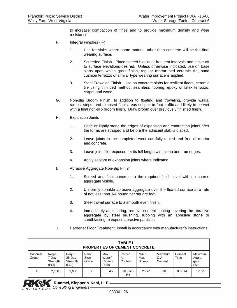
Frankfort Public Service District Water Improvement Project FWAT-16-06 Wiley Ford, West Virginia Water Storage Tank – Contract 6
Rummel, Klepper & Kahl, LLP Consulting Engineers
03300 - 26
to increase compaction of fines and to provide maximum density and wear resistance.
F. Integral Finishes (IF)
1. Use for slabs where some material other than concrete will be the final wearing surface.
2. Screeded Finish - Place screed blocks at frequent intervals and strike off to surface elevations desired. Unless otherwise indicated, use on base slabs upon which grout finish, regular mortar bed ceramic tile, sand cushion terrazzo or similar type wearing surface is applied.
3. Steel Troweled Finish - Use on concrete slabs for resilient floors, ceramic tile using thin bed method, seamless flooring, epoxy or latex terrazzo, carpet and wood.
G. Non-slip Broom Finish: In addition to floating and troweling, provide walks, ramps, steps, and exposed floor areas subject to foot traffic and likely to be wet with a final non-slip broom finish. Draw broom over previously finished finish.
H. Expansion Joints
1. Edge or lightly stone the edges of expansion and contraction joints after the forms are stripped and before the adjacent slab is placed.
2. Leave joints in the completed work carefully tooled and free of mortar and concrete.
3. Leave joint filler exposed for its full length with clean and true edges.
4. Apply sealant at expansion joints where indicated.
I. Abrasive Aggregate Non-slip Finish
1. Screed and float concrete to the required finish level with no coarse aggregate visible.
2. Uniformly sprinkle abrasive aggregate over the floated surface at a rate of not less than 1/4 pound per square foot.
3. Steel trowel surface to a smooth even finish.
4. Immediately after curing, remove cement coating covering the abrasive aggregate by steel brushing, rubbing with an abrasive stone or sandblasting to expose abrasive particles.
J. Hardener Floor Treatment: Install in accordance with manufacturer’s instructions.
TABLE I PROPERTIES OF CEMENT CONCRETE
Concrete Group
Req’d. 7-Day Strength (PSI)
Req’d. 28-Day Strength (PSI)
Reinf. Steel Grade
Max. Water/ Cement Ratio
Percent Air Content
Min./ Max. Slump
Maximum C3A Content
Cement Type
Maximum Aggre-gate Size
E 2,000 3,000 60 0.45 5% +or - 1%
2"- 4" 8% II or IIA 1-1/2"

Frankfort Public Service District Water Improvement Project FWAT-16-06 Wiley Ford, West Virginia Water Storage Tank – Contract 6
Rummel, Klepper & Kahl, LLP Consulting Engineers
03300 - 27
TABLE II CONCRETE FINISH SCHEDULE
Location Concrete Group Finish Remarks
Weir Footing E ST Surface
Weir Wall E SFF Vertical Wall Face
Weir Wall E NSBF Top Surface
Legend: SFF= Smooth Form Finish FF= Float Finish IF= Integral Finish
ST= Steel Trowel NSBF = Non-Slip Broom Finish
For precast structures see respective specifications for concrete finish.
3.17 HOT WEATHER REQUIREMENTS
A. Hot weather conditions are deemed to exist when the temperature in the forms is 75oF or above, or a combination of high air temperature, low relative humidity and wind velocity impairs the quality of fresh or hardened concrete. Take protective measures for mixing, transporting and placing concrete in accordance with ACI 305.
B. The temperature of the concrete at the place of discharge may not exceed 85oF.
1. If ice is used to lower temperature, place crushed, shaved or chipped ice directly into the mixer as part or all of the mixing water. Mix until ice is completely melted.
2. Record the concrete temperature at the time of discharge.
C. Do not add water that will cause the proportions to exceed the maximum water-cement ratio shown in Table I.
1. Notify the resident project representative before adding any water to the concrete mix.
2. Record the amount of water added to the concrete at the jobsite.
D. Discharge concrete within 45 minutes or 100 revolutions, whichever occurs first, after the first mixing of cement and aggregates.
E. Placing and Curing
1. Place concrete promptly upon arrival.
2. Provide at least one standby vibrator for each 3 vibrators in use.
a. Protect concrete from direct sunlight. Keep forms covered and moist by means of water sprinkling or the application of continuously wetted burlap or cotton mats for a minimum of 24 hours.
3. When forms are removed, provide wet cover to the newly exposed surfaces to avoid exposure to hot sun and wind.
4. Continue specified water curing methods for 10 days. Leave covering in
Frankfort Public Service District Water Improvement Project FWAT-16-06 Wiley Ford, West Virginia Water Storage Tank – Contract 6
Rummel, Klepper & Kahl, LLP Consulting Engineers
03300 - 28
place 4 additional days. Do not permit alternate wetting and drying cycles.
5. For slabs on grade, beam and deck concrete, and other horizontal placements, protect the surface between finishing operations using one or more of the following methods:
a. Careful use of a fog nozzle.
b. Spreading and removing polyethylene sheeting between finishing operations.
c. Application of monomolecular film after the strike off.
3.18 COLD WEATHER REQUIREMENTS
A. Cold weather is defined any time when the daily temperature is 40oF or lower during placement and the protection period.
B. Protect concrete surfaces from freezing for at least 24 hours after placement.
C. All surfaces in contact with newly-placed concrete including formwork, reinforcement and subgrade must be above 35oF.
D. Place concrete at a temperature of not less than 55oF. Mix concrete at a temperature between
1. 60oF and 70oF when outside air temperature is above 30oF.
2. 65oF and 75oF when outside air temperature is between 0oF and 30oF.
3. 70oF and 80oF when outside air temperature is below 0oF.
E. Follow concrete placement with tarpaulins or other readily movable coverings, so only a few feet of concrete is exposed to the outside air at any time.
F. Maintain the temperature and moisture conditions specified in all parts of the newly-placed concrete by covering, insulating, housing or heating. Arrange for protection methods in advance of placement.
G. Maintain concrete at a temperature of not less than 50oF nor more than 70oF for a period of 3 days after placement.
H. Do not remove forms during the initial protection period.
I. Protect insulation against wetting that will impair its insulating value using moisture-proof cover material. Keep insulation in close contact with concrete.
J. Construct enclosure to withstand wind and snow loads and be reasonably air-tight. Provide sufficient space between the concrete and enclosure to permit free circulation of heated air.
K. Use vented heaters. Do not permit heaters to heat or dry concrete locally.
L. Maintain relative humidity above 40% within heated enclosures before

Frankfort Public Service District Water Improvement Project FWAT-16-06 Wiley Ford, West Virginia Water Storage Tank – Contract 6
Rummel, Klepper & Kahl, LLP Consulting Engineers
03300 - 29
construction supports are removed.
M. Monitor temperature to insure concrete is kept within specified limits recording time and concrete temperature every 8 hours.
N. Assure concrete has developed necessary strength before removing forms. Provide additional test cylinders with the same protection as the structure they represent to verify concrete strength before construction supports are removed.
O. If water curing is used, terminate at least 12 hours before end of temperature protection period. Permit concrete to dry.
P. After the required protection period, gradually reduce the concrete temperature within an enclosure or insulation at a rate not to exceed 20o per day until the outside temperature has been reached.
Q. Apply membrane-forming curing compound to concrete surfaces during the first period of above-freezing temperatures after forms are stripped and before air temperature rises to 50o. Apply membrane-forming curing compound to slabs as soon as finishing operations are completed, except where live steam curing is used.
3.19 CURBING AND SIDEWALKS
A. Shall be installed using materials and practices set forth in these specifications.
B. Shall be as detailed on the contract documents.
3.20 TESTING
A. General - Concrete materials and operations will be tested and inspected as the work progresses. Failure to detect any defective work or material shall not in any way prevent later rejection when either such defect is discovered nor shall it obligate the Authority for final acceptance.
B. Testing Services - The following testing services shall be performed by the designated testing agency:
1. Perform compressive strength, slump and air content tests of the concrete during construction in accordance with the following procedures:
a. Secure composite samples in accordance with ASTM C172. Each sample shall be obtained from a different batch of concrete on a random basis, avoiding any selection of the test batch other than by a number selected at random before commencement of concrete placement.
b. Mold and cure three specimens from each sample in accordance with ASTM C31. Any deviations from the requirements of this standard shall be recorded in the test report.
c. Test specimens in accordance with ASTM C39. Test 2 cylinders at 7 days; test 2 cylinders at 28 days. Hold the remaining cylinder for testing in the event that any of the other cylinders are
Frankfort Public Service District Water Improvement Project FWAT-16-06 Wiley Ford, West Virginia Water Storage Tank – Contract 6
Rummel, Klepper & Kahl, LLP Consulting Engineers
03300 - 30
damaged prior to testing. The acceptance test results shall be the average of the strengths of the two cylinders tested at 28 days. If one cylinder in a test manifests evidence of improper sampling, molding or testing, it shall be discarded and the strength of the remaining cylinder shall be considered the test result. Should both cylinders in a test show any of the above defects, the entire test shall be discarded.
d. Make at least one strength test for each 50 cu. yd., or fraction thereof, of each mixture design of concrete placed in any 1 day. When the total quantity of concrete with a given mixture design is less than 20 cu. yd., the strength tests may be waived by the Engineer if, in the Engineer’s judgment, adequate evidence of satisfactory strength is provided, such as strength test results for the same kind of concrete supplied on the same day and under comparable conditions to other work or other projects.
2. Determine slump of the concrete sample for each strength test and whenever consistency of concrete appears to vary, using ASTM C143.
3. Determine air content of the concrete sample for each strength test in accordance with ASTM C231, ASTM C173, or ASTM C138.
4. Determine temperature of the concrete sample for each strength test.
C. Additional Services When Required - The following services shall be performed by the testing agency when required by the Owner at the Contractor's expense:
1. Inspect concrete batching, mixing and delivery operations to the extent
deemed necessary by the Owner.
2. Sample concrete at point of placement and perform required tests.
3. Review the manufacturer's report for each shipment of cement and reinforcing steel and conduct laboratory tests or spot checks of the materials as received for compliance with specifications.
4. Mold three specimens from each sample (in addition to those required in Section 3.19.B.1.b) in accordance with ASTM C31 and field cure in or on the structure providing the same method of cure for the specimens as that which the structure receives.
D. Other Services As Needed - The following services shall be performed by the testing agency at the Contractor's expense:
1. Additional testing and inspection required because of changes in materials or proportions requested by the Contractor.
2. Additional testing of materials or concrete occasioned by their failure by test or inspection to meet specification requirements.
E. Duties and Authorities of Designated Testing Agency:
1. Representatives of the agency shall inspect, sample and test the materials and the production of concrete as required by the Authority.

Frankfort Public Service District Water Improvement Project FWAT-16-06 Wiley Ford, West Virginia Water Storage Tank – Contract 6
Rummel, Klepper & Kahl, LLP Consulting Engineers
03300 - 31
When it appears that any material furnished or work performed by the Contractor fails to fulfill specification requirements, the testing agency shall report such deficiency to the Authority and the Contractor.
2. The agency shall report all test and inspection results to the Authority and Contractor immediately after they are performed. All test reports shall include the exact location in the work at which the batch represented by a test was deposited. Reports of strength tests shall include detailed information on storage and curing of specimens prior to testing.
3. The testing agency and its representatives are not authorized to revoke, alter, relax, enlarge or release any requirement of the Contract Documents, nor to approve or accept any portion of the work.
F. Responsibilities and Duties of Contractor:
1. The Contractor shall provide the necessary testing services for the following:
a. Qualification of proposed materials and the establishment of mixture designs.
b. Other testing services needed or required by the Contractor.
2. The use of testing services shall in no way relieve the Contractor of the responsibility to furnish materials and construction in full compliance with the Contract Documents.
3. The Contractor shall submit to the Authority the concrete materials and the concrete mix designs proposed for use with a written request for acceptance. This submittal shall include the results of all testing performed to qualify the materials and to establish the mix designs. No concrete shall be placed in the work until the Contractor has received such acceptance in writing.
4. To facilitate testing and inspection, the Contractor shall:
a. Furnish any necessary labor to assist the testing agency in obtaining and handling samples at the project or other sources of materials.
b. Advise the testing agency sufficiently in advance of operations to allow for completion of quality tests and for the assignment of personnel.
c. Provide and maintain for the sole use of the testing agency adequate facilities for safe storage and proper curing of concrete test specimens on the project site for the first 24 hours as required by ASTM C31.
3.21 EVALUATION AND ACCEPTANCE OF CONCRETE
A. Evaluation of Test Results:

Frankfort Public Service District Water Improvement Project FWAT-16-06 Wiley Ford, West Virginia Water Storage Tank – Contract 6
Rummel, Klepper & Kahl, LLP Consulting Engineers
03300 - 32
1. Test results for standard molded and standard cured test cylinders shall be evaluated separately for each specified concrete mixture design. Such evaluation shall be valid only if tests have been conducted in accordance with procedures specified in Section 3.19.
2. For evaluation, each specified mixture design shall be represented by at least five tests.
B. Acceptance of Concrete
1. Strength - The strength level of the concrete will be considered satisfactory so long as the averages of all sets of three consecutive strength test results equal or exceed the specified strength f’c, and no individual strength test result falls below the specified strength f’c by more than 500 psi.
2. Durability – The durability level of the concrete will be considered satisfactory so long as the requirements of ACI 301, Section 1.7.5 are met.
C. Testing of Concrete In Place:
1. Testing by impact hammer, sonoscope, or other nondestructive device may be permitted by the Owner to determine relative strengths at various locations in the structure as an aid in evaluating concrete strength in place or for selecting areas to be cored. Such tests, unless properly calibrated and correlated with other test data, shall not be used as a basis for acceptance or rejection.
2. Core tests
a. Where required, cores at least 2 in. in diameter shall be obtained and tested in accordance with ASTM C42. If the concrete in the structure will be dry under service conditions, the cores shall be air dried (temperature 60 degrees F to 80 degrees F, relative humidity less than 60 percent) for 7 days before testing and shall be tested dry. If the concrete in the structure will be more than superficially wet under service conditions, the cores shall be tested after moisture conditioning in accordance with ASTM C42.
b. At least three representative cores shall be taken from each member or area of concrete in place that is considered potentially deficient. The location of cores shall be determined by the Authority to least impair the strength of the structure. If, before testing, one or more of the cores shows evidence of having been damaged subsequent to or during removal from the structure, it shall be replaced with a new core.
c. The strength level of concrete in the area represented by a core test will be considered adequate if the average strength of the cores is equal to at least 85 percent of specified strength f’c and if no single core is less than 75 percent of the specified strength f’c.
Frankfort Public Service District Water Improvement Project FWAT-16-06 Wiley Ford, West Virginia Water Storage Tank – Contract 6
Rummel, Klepper & Kahl, LLP Consulting Engineers
03300 - 33
d. Core holes shall be filled with low slump concrete or mortar. See Section 3.13, Repair of Surface Defects.
3.22 ACCEPTANCE OF STRUCTURE
A. General:
1. Completed concrete work which meets all applicable requirements will be accepted without qualification.
2. Completed concrete work, which fails to meet one or more requirements, but which has been repaired to bring it into compliance will be accepted without qualification.
3. Completed concrete work which fails to meet one or more requirements and which cannot be brought into compliance may be accepted or rejected as provided in these Specifications or in the Contract Documents. In this event, modifications may be required to assure that the work complies with the design intent.
B. Dimensional Tolerances:
1. Formed surfaces resulting in concrete outlines smaller than permitted by the tolerances of ACI 117 shall be considered potentially deficient in strength and subject to the provisions of Section 3.21.D.
2. Formed surfaces resulting in concrete outlines larger than permitted by the tolerances of ACI 117 may be rejected and the excess material shall be subject to removal. If removal of the excess material is permitted, it shall be accomplished in such a manner as to maintain the strength of the section and to meet all other applicable requirements of function and appearance.
3. Concrete members cast in the wrong location may be rejected if the strength, appearance or function of the structure is adversely affected or misplaced items interfere with other construction.
4. Inaccurately formed concrete surfaces exceeding the limits of ACI 117, and which are exposed to view, may be rejected and shall be repaired or removed and replaced if required.
5. Finished slabs exceeding the tolerances of Section 3.16 may be repaired provided that strength or appearance is not adversely affected. High spots may be removed with terrazzo grinder, low spots filled with a patching compound, or other remedial measures performed as permitted.
C. Appearance:
1. Other concrete exposed to view with defects which adversely affect the appearance of the specified finish may be repaired only by acceptable methods.
2. Concrete not exposed to view is not subject to rejection for defective appearance.
Frankfort Public Service District Water Improvement Project FWAT-16-06 Wiley Ford, West Virginia Water Storage Tank – Contract 6
Rummel, Klepper & Kahl, LLP Consulting Engineers
03300 - 34
D. Strength of Structure:
1. The strength of the structure in place will be considered potentially deficient if it fails to comply with any requirements, which control the strength of the structure, including but not necessarily limited to the following conditions:
a. Low concrete strength as designated in Section 3.20
b. Reinforcing steel size, quantity, strength, position, or arrangement at variance with the requirements of Section 3.03, Reinforcement, or the Contact Drawings.
c. Concrete, which differs from the required dimensions or location in such a manner as to reduce the strength.
d. Curing less than that specified.
e. Inadequate protection of concrete from extremes of temperature during early stages of hardening and strength development.
f. Mechanical injury (as defined in Section 3.11.F), construction fires, accidents or premature removal of formwork likely to result in deficient strength.
g. Poor workmanship likely to result in deficient strength.
2. Structural analysis and/or additional testing may be required when the strength of the structure is considered potentially deficient.
3. Core tests in accordance with Section 3.20.C.2 may be required when the strength of the concrete in place is considered potentially deficient.
4. If core tests are inconclusive or impractical to obtain or if structural analysis does not confirm the safety of the structure, load tests may be required and there results evaluated in accordance with ACI 318.
5. Concrete work judged inadequate by structural analysis or by results of a load test shall be reinforced with additional construction if so directed by the Authority, or shall be replaced, at the Contractor’s expense.
6. The Contractor shall pay all costs incurred in providing the additional testing, analysis and/or engineering services required by this section.
E. Durability of Structure
The durability level of the structure will be considered satisfactory so long as the requirements of ACI 301, Section 1.7 are met.
END OF SECTION

Frankfort Public Service District Water Improvement Project FWAT-16-06 Wiley Ford, West Virginia Water Storage Tank – Contract 6
Rummel, Klepper & Kahl, LLP Consulting Engineers
03300 - 35

Frankfort Public Service District Water Improvement Project FWAT-16-06 Wiley Ford, West Virginia Water Storage Tank – Contract 6
Rummel, Klepper & Kahl, LLP Consulting Engineers
03300 - 36
THIS PAGE LEFT BLANK

Frankfort Public Service District Water Improvement Project FWAT-16-06 Wiley Ford, West Virginia Water Storage Tank – Contract 6
Rummel, Klepper & Kahl, LLP Consulting Engineers
03400 - 1
SECTION 03400
PRECAST CONCRETE STRUCTURES
PART 1 - GENERAL
1.01 DESCRIPTION
A. The work of this section includes, but is not limited to:
1. Valve Vaults
2. Meter Vaults
B. Related work specified elsewhere:
1. Section 02300 – Earthwork
2. Section 02535 - Pipe and Pipe Fittings
3. Section 03600 - Grout
4. Section 15950–Adjusting, Balancing Gravity Pipe Flow–Pressure Testing
1.02 QUALITY ASSURANCE
A. Design Criteria
1. Watertight precast reinforced air-entrained concrete structures designed to ASTM C890, A-16 live loading and installation conditions, and manufactured to conform to ASTM C913.
2. Minimum 28-day Compressive Strength: 5,000 psi.
3. Honeycombed or retempered concrete will not be acceptable.
B. Reference Standards
1. American Society for Testing and Materials (ASTM)
a. ASTM C858 - Underground Precast Concrete Utility Structures.
b. ASTM C890 - Standard Practice for Minimum Structural Design Loading for Monolithic or Sectional Precast Concrete Water and Wastewater Structures.
c. ASTM C891 - Practice for Installation of Underground Precast Concrete Utility Structures.
d. ASTM C913 - Specifications for Precast Concrete Water and Wastewater Structures.
1.03 SUBMITTALS

Frankfort Public Service District Water Improvement Project FWAT-16-06 Wiley Ford, West Virginia Water Storage Tank – Contract 6
Rummel, Klepper & Kahl, LLP Consulting Engineers
03400 - 2
A. Shop Drawings and Product Data
1. Submit detailed shop drawings to the Engineer for approval prior to fabrication.
2. Include details of reinforcing steel, joint design, concrete mix design, and design calculations.
B. Submit certification from the precast structures manufacturer attesting that the structures meet or exceed Contract Specifications.
1.04 PRODUCT DELIVERY, STORAGE AND HANDLING
A. Transport and handle precast concrete units with equipment designed to protect the units from damage.
B. Do not place units in position which will cause overstress, warp or twist.
C. Separate stacked members with battens across the full width of each bearing point.
D. Stack so that lifting devices are accessible and undamaged, and identification marks are discernible.
PART 2 - PRODUCTS
2.01 MATERIALS
A. Portland Cement: ASTM C150, Type II.
B. Coarse Aggregates: ASTM C33; Graded 1" to No. 4 Sieve.
C. Sand: ASTM C33; 2.35 fineness modulus.
D. Water: Potable; clean and free of injurious amounts of acids, alkalis, salts, organic materials, or other substances that may be incompatible with concrete or steel.
E. Air-Entraining Admixtures: ASTM C260.
F. Reinforced Steel
1. Deformed Bars: ASTM A615, Grade 60
2. Welded Wire Fabric: ASTM A185.
G. Joint Sealant: ASTM C990.
2.02 MIXES
Design concrete mix to produce the required concrete strength, air-entrainment, watertight properties, and loading requirements.
2.03 FABRICATION AND MANUFACTURE
Frankfort Public Service District Water Improvement Project FWAT-16-06 Wiley Ford, West Virginia Water Storage Tank – Contract 6
Rummel, Klepper & Kahl, LLP Consulting Engineers
03400 - 3
Fabricate precast reinforced concrete structures in accordance with ASTM C913, to the dimensions indicated on the Contract Drawings, and to the specified design criteria.
PART 3 - EXECUTION
3.01 INSTALLATION
A. Unless otherwise specified herein below, the precast units shall be installed in accordance with ASTM C891.
B. Install precast concrete units to the elevation and location indicated on the Contract Documents.
C. Install required pipe connections, valves, baffles and other appurtenances as indicated on the Contract Drawings.
3.02 BACKFILLING STRUCTURES
A. Do not backfill precast concrete structures until after examination and approval of the Engineer.
B. Backfill structures in accordance with Section 02300 - Earthwork.
END OF SECTION

Frankfort Public Service District Water Improvement Project FWAT-16-06 Wiley Ford, West Virginia Water Storage Tank – Contract 6
Rummel, Klepper & Kahl, LLP Consulting Engineers
03400 - 4
THIS PAGE LEFT BLANK
Frankfort Public Service District Water Improvement Project FWAT-16-06 Wiley Ford, West Virginia Water Storage Tank – Contract 6
Rummel, Klepper & Kahl, LLP Consulting Engineers
03600 - 1
SECTION 03600
GROUT
PART 1 - GENERAL
1.01 DESCRIPTION
A. The work of this section includes, but is not limited to:
1. Portland Cement Grout
2. Rapid-curing Epoxy Grout
3. Non-shrink Cementitious Grout
1.02 SUBMITTALS
A. Submit a Statement of Compliance, together with supporting data, from the materials suppliers attesting the conformance of products and ingredients with these specifications.
B. Submit manufacturer’s instructions for mixing, handling, surface preparation, and placing the epoxy type and the non-shrink type grouts.
PART 2 - PRODUCTS
2.01 PORTLAND CEMENT
A. ASTM C150, Type I and II.
2.02 WATER
A. Potable; containing no impurities, suspended particles, algae or dissolved natural salts in quantities that will cause:
1. Corrosion of steel,
2. Volume of change that will increase shrinkage cracking,
3. Efflorescence, or
4. Excess air entraining
2.03 FINE AGGREGATE
A. Washed natural sand.
B. Gradation in accordance with ASTM C33 and represented by a smooth granulometric curve within the required limits.
C. Free from injurious amounts of organic impurities as determined by ASTM C40.

Frankfort Public Service District Water Improvement Project FWAT-16-06 Wiley Ford, West Virginia Water Storage Tank – Contract 6
Rummel, Klepper & Kahl, LLP Consulting Engineers
03600 - 2
2.04 RAPID-CURING EPOXY GROUT
A. High strength, three component epoxy grout formulated with thermosetting resins and inert fillers.
B. Grout shall be rapid-curing, have high adhesion, and be resistant to ordinance chemicals, acids and alkalies.
C. Physical Properties Reference Spec.
Compressive Strength 12,000 psi (7-day) ASTM C579 Tensile Strength 2,000 psi minimum ASTM C307 Coefficient of Expansion 30x10-6 in/in/oF ASTM C531 Shrinkage None ASTM C827
2.05 NON-SHRINK CEMENTITIOUS GROUT
A. Pre-mixed ready for use formulation requiring only the addition of water; non-shrink, non-corrosive, non-metallic, non-gas forming, no chlorides.
B. Certified to maintain initial placement volume or expand after set and meet the following minimum properties when tested in accordance with Corps of Engineers Specification CRD-C621, or Type D non-shrink grout:
Setting Time: Initial 2 hours (Approx.) ASTM C191 Final 3 hours (Approx.) Expansion: 0.10% - 0.4% Maximum Compressive Strength: 1 day 4,000 psi CRD-C621 7 days 7,000 psi 28 days 10,000 psi - 10,800 psi.
PART 3 - EXECUTION
3.01 SURFACE PREPARATION
A. Remove defective concrete, laitance, dirt, oil, grease and other foreign material from concrete surfaces by brushing, hammering, chipping or other similar means until a sound, clean concrete surface is achieved.
B. Lightly roughen the concrete, but not enough to interfere with the proper placement of grout.
C. Remove foreign materials from metal surfaces in contact with grout.
D. Align, level and maintain final positioning of components to be grouted.
E. Task special precautions during period of extreme weather conditions in accordance with the manufacturer’s written instructions.
F. Saturate concrete surfaces with clean water; remove excess water, level none standing.

Frankfort Public Service District Water Improvement Project FWAT-16-06 Wiley Ford, West Virginia Water Storage Tank – Contract 6
Rummel, Klepper & Kahl, LLP Consulting Engineers
03600 - 3
3.02 FORMWORK
A. Construct leakproof forms anchored and shored to withstand grout pressures.
B. Provide clearance between the formwork and the area to be grouted to permit proper placement of grout.
3.03 MIXING
A. Portland Cement Grout
1. Prepare grout composed of Portland cement, sand and water; do not use ferrous aggregate or staining ingredients in grout mix.
2. Use proportions of 2 parts sand and 1 part cement, measured by volume.
3. Prepare grout with sufficient water to obtain consistency to permit placing and packing.
4. Mix water and grout in two steps; pre-mix using approximately 2/3 of the water; after partial mixing, add the remaining amount of water to bring mix to the desired placement consistency and continue mixing 2-3 minutes.
5. Mix only that quantity of grout that can be placed within 30 minutes after mixing.
6. After the grout has been mixed, do not add more water for any reason.
B. Epoxy Grout & Non-Shrink Cementitious Grout: Mix and prepare epoxy grout and non-shrink cementitious grout in strict accordance with the manufacturer’s instructions.
C. Mix grout components as close to the work area as possible and transport the mixture quickly and in a manner that does not permit segregation of materials.
3.04 PLACING
A. Place grout material quickly and continuously.
B. Do not use pneumatic-pressure or dry-packing methods.
C. Apply grout from one side only to avoid entrapping air.
D. Do not vibrate the placed grout mixture or permit it to be placed if the area is being vibrated by nearby equipment.
E. The final installation shall be thoroughly compacted and free of air pockets.
F. Do not remove leveling shims for at least 48 hours after grout has been placed.
3.05 CURING
Frankfort Public Service District Water Improvement Project FWAT-16-06 Wiley Ford, West Virginia Water Storage Tank – Contract 6
Rummel, Klepper & Kahl, LLP Consulting Engineers
03600 - 4
A. After grout has attained its initial set, keep damp for a minimum of 3 days.
B. Prevent rapid loss of water from the grout during the first 48 hours by the use of an approved membrane curing compound or with the use of the wet burlap method.
END OF SECTION
Frankfort Public Service District Water Improvement Project FWAT-16-06 Wiley Ford, West Virginia Water Storage Tank – Contract 6
Rummel, Klepper & Kahl, LLP Consulting Engineers
07100 - 1
SECTION 07100
WATERPROOFING AND DAMPPROOFING
PART 1 - GENERAL
1.01 DESCRIPTION
A. Work included: Provide materials, labor and equipment required to perform all waterproofing and dampproofing Work indicated on the drawings, as specified herein, and as needed for a complete and proper installation.
B. Related work: Documents affecting work of this Section include, but are not
necessarily limited to, General Conditions, Supplementary Conditions, and Sections in Division 1 of these Specifications.
1.02 QUALITY ASSURANCE
A. Use adequate numbers of skilled workmen who are thoroughly trained and experienced in the necessary crafts and who are completely familiar with the specified requirements and the methods needed for proper performance of the work of this Section.
B. Waterproofing membrane shall be compatible with waterproofing material and installed by methods approved by the membrane manufacturer.
1.03 PRODUCT HANDLING
A. Deliver the materials to the job site and store, in a safe are, out of the way of traffic and shored up off the ground surface, complying in all respects with product manufacturers recommendations.
B. Pallets of material shall be stored at job site on a level surface and protected from the weather. Membrane shall be left on pallets as received and not stacked more than one pallet high.
1.04 SUBMITTALS
A. Comply with pertinent provisions of Section 01300.
B. Product data: Within 21 calendar days after the Contractor has received the Owner's Notice to Proceed, submit:
1. Materials list of items proposed to be provided for all work under this Section;
2. Manufacturers' specifications and other data needed to prove compliance with the manufacturer’s recommended installation procedures which, when approved by the Engineer, will become the basis for accepting or rejecting actual installation procedures used on the Work.
1.05 CAUTIONS AND WARNINGS
A. Primers and mastics are solvent-based liquids. Prior to the use of any product,
Frankfort Public Service District Water Improvement Project FWAT-16-06 Wiley Ford, West Virginia Water Storage Tank – Contract 6
Rummel, Klepper & Kahl, LLP Consulting Engineers
07100 - 2
consult the manufacturer's product label for handling, use and storage instructions.
B. Adhere strictly to all manufacturer's cautions, warnings and product safety and handling instructions.
PART 2 - PRODUCTS
2.01 MEMBRANE WATERPROOFING
At foundation walls below grade, use Premoulded Membrane with Plasmatic Core as manufactured by W. R. Meadows, Inc., 2100 Monroe Street, York, PA 17405. Phone: (717) 792-2627, Fax: (717) 792-0151, or acceptable equivalent. Provide joint sealing strips, bonding agents and other materials required for a complete system as recommended by manufacturer.
2.02 COATING FOR MEMBRANE WATERPROOFING
The coating for membrane waterproofing shall consist of a prime coat, three mop coats, and two layers of fabric. Membrane waterproofing shall be applied to the face of construction joints as shown on the Contract Drawings for a width of 16-inches minimum centered on the joint.
2.03 WATERPROOFING MEMBRANE
The adhesive side of the membrane shall be protected with a special release paper that can be easily removed for installation. The membrane shall conform to the following requirements:
Test Property Test Method Specification Limit
Grab Tensile Strength ASTM D 5034 70
Pliability, 180-degree bend ASTM D 146 Unaffected
Resistance to Puncture ASTM E 154 40
Permeance, Permeabiltiy ASTM E 96 –B 0.1
Weight, oz/SY, Min. ASTM D 3776 40
2.04 DAMPPROOFING
Dampproofing material shall be asphaltic coatings and shall consist of two prime coats and one seal coat. Dampproofing shall be applied to concrete surfaces that will be below ground. Dampproofing asphalt shall be hot applied and shall conform to ASTM D449. The primer shall conform to ASTM D41.
2.05 OTHER MATERIALS
Provide other materials, not specifically described but required for a complete and proper installation, as selected by the Contractor subject to the acceptance of the Engineer.

Frankfort Public Service District Water Improvement Project FWAT-16-06 Wiley Ford, West Virginia Water Storage Tank – Contract 6
Rummel, Klepper & Kahl, LLP Consulting Engineers
07100 - 3
PART 3 - EXECUTION
3.01 DELIVERIES
Stockpile materials sufficiently in advance of need to assure their availability in a timely manner for this Work. Make as many trips to the job site as are needed to deliver materials of this Section in a timely manner to ensure orderly progress of the work.
3.02 COMPLIANCE
Do not permit materials not complying with the provisions of this Section to be brought onto or to be stored at the job site. Promptly remove non-complying materials from the job site and replace with materials meeting the requirements of this Section.
3.03 SURFACE CONDITIONS
Examine the areas and conditions under which work of this Section will be performed. Correct conditions detrimental to timely and proper completion of the Work. Do not proceed until unsatisfactory conditions are corrected.
3.04 INSTALLATION
A. Install entire waterproofing system in strict accordance with system manufacturer's written instructions.
1. The concrete surface to receive membrane must be smooth and free from all sharp projections, dirt, dust and loose materials. Repair all voids and holes.
2. At foundation walls, continue application over the footings and under perimeter drains.
a) Backfilling may be done as soon as installation is completed and should be done within 4 hour after material is applied to the wall. Backfilling can be done as installation progresses. Care shall be taken to ensure that backfilling does not disrupt the bond of the membrane to the walls.
3. At deck, install sheets in continuous bed of hot asphalt.
B. Materials shall be applied at a temperature above 40 degrees F., unless specifically listed for application below .40 degrees F. Do not apply materials when there is ice, frost or dampness visible on the surface to be waterproofed or damp proofed.
END OF SECTION

Frankfort Public Service District Water Improvement Project FWAT-16-06 Wiley Ford, West Virginia Water Storage Tank – Contract 6
Rummel, Klepper & Kahl, LLP Consulting Engineers
07100 - 4
THIS PAGE LEFT BLANK

Frankfort Public Service District Water Improvement Project FWAT-16-06 Wiley Ford, West Virginia Water Storage Tank – Contract 6
Rummel, Klepper & Kahl, LLP Consulting Engineers
09900 - 1
SECTION 09900
PAINTING
PART 1 - GENERAL
1.01 Description
A. Work Included:
The type of material to be used and the number of coats to be applied are listed in the "Painting Schedule" in Part 3.00 of this Section of these Specifications.
B. The term "paint", as used herein, includes enamels, paints, sealer, fillers, emulsions, and other coatings whether used as prime, intermediate, or finish coat.
1.02 Quality Assurance
A. Use only qualified journeymen painters for the mixing and application of paint on exposed surfaces; in the acceptance or rejection of installed painting, no allowances will be made for lack of skill on the part of painter.
B. Complying with all pertinent codes and regulation.
1.03 Submittals
In each case where material proposed is not the material specified or specifically described as an acceptable alternate in this Section of these Specifications, submit for the Engineer's review the current recommended method of application published by the manufacturer of the proposed material.
1.04 Product Handling
A. Deliver all paint materials to the job site in their original unopened containers with all labels intact and legible at time of use.
B. Store only the approved materials at the job site and store only on a suitable and designated area restricted to the storage of paint materials and related equipment.
1. Use all means necessary to ensure the safe storage and use of paint materials and the prompt and safe disposal of waste.
2. Use all means necessary to protect paint materials before, during and after application and to protect the installed work and materials of all other trades.
C. In the event of damage, immediately make all repairs and replacements necessary to the approval of the Engineer and at no additional cost to the Owner.

Frankfort Public Service District Water Improvement Project FWAT-16-06 Wiley Ford, West Virginia Water Storage Tank – Contract 6
Rummel, Klepper & Kahl, LLP Consulting Engineers
09900 - 2
1.05 Extra Stock
Upon completion of this portion of the Work, deliver to the Owner an extra stock of paint equaling approximately 10% of each color use in each coating material used, with all such extra stock tightly sealed in clearly labeled containers.
PART 2 - PRODUCTS
2.01 Paint Materials
A. Manufacturer:
1. All paint materials selected for coating systems for each type of surface shall be the product of a single manufacturer.
2. Pittsburgh Paint, Glidden, Devoe, or Sherwin Williams or equal will be accepted subject to painting systems approval.
B. Compatibility:
1. All paint materials and equipment shall be compatible in use: finish coats shall be compatible with prime coats; prime coats shall be compatible with the surface to be coated; all tools and equipment shall be compatible with the coating to be applied.
2. Any paint used over metal primer shall be compatible with that primer.
3. Thinners, when used, shall be only those thinners recommended for that purpose by the manufacturer of the material to be thinned.
4. The use of lead base paint is prohibited.
PART 3 - EXECUTION
3.01 Surface Condition
A. Prior to all work of this Section, carefully inspect the installed work of all other trades and verify that all such work is complete to a point where this installation may properly commence.
Verify that paint finishes may be applied in strict accordance with all pertinent codes and regulations and the requirements of these Specifications.
B. In the event of discrepancy, immediately notify the Engineer. Do not proceed with installation in areas of discrepancy until all such discrepancies have been fully resolved.
3.02 Preparation of Surfaces
A. General: Prior to all surface preparation and painting operations, completely mask, remove, or otherwise adequately protect all hardware, accessories, machined surfaces, plates, lighting fixtures, cabinets, and similar items in contact with painted surfaces but not scheduled to receive paint.

Frankfort Public Service District Water Improvement Project FWAT-16-06 Wiley Ford, West Virginia Water Storage Tank – Contract 6
Rummel, Klepper & Kahl, LLP Consulting Engineers
09900 - 3
B. Spot prime all exposed nails and other metals which are to be painted with emulsion paints, using a primer recommended by the manufacturer of the coating system.
C. Before applying paint or other surface treatment, thoroughly clean all surfaces involved. Schedule all cleaning and painting so that dust and other contaminants from the cleaning process will not fall on wet newly painted surfaces.
3.03 Preparation of Wood Surfaces
A. Clean all wood surfaces until they are free from dirt, oil, and all other foreign substance.
B. Unless specifically noted to be left rough, smooth all finished wood surfaces exposed to view, using the proper sandpaper.
3.04 Preparation of Metal Surfaces
Thoroughly clean all surfaces until they are completely free from dirt, oil and grease. Allow to dry thoroughly before application of paint.
3.05 Preparation of Concrete Block Surfaces
Thoroughly clean all surfaces until they are completely free from dirt, dust, oil, grease, and all other foreign substances.
3.06 Paint Application
A. Paint all surfaces except glass, flat concrete and similar items pre-finished and not called out as unfinished.
1. Paint all grills and other pre-finished items where the factory pre-finished is not in accordance with the Painting Schedule and color selection.
2. Allow sufficient drying time between coats.
3. Modify the period as recommended by the material manufacturer to suit adverse weather conditions.
B. Environmental Conditions:
1. Comply with the manufacturer's recommendations as to environmental conditions under which the coating systems may be applied.
2. Do not apply paint in areas where dust is being generated.
C. Moisture Content:
1. Use a moisture-meter approved by the Engineer to test surfaces.
2. Do not apply the initial coating until moisture- meter reading is within limits recommended by the paint materials manufacturer.

Frankfort Public Service District Water Improvement Project FWAT-16-06 Wiley Ford, West Virginia Water Storage Tank – Contract 6
Rummel, Klepper & Kahl, LLP Consulting Engineers
09900 - 4
D. Defects:
Sand and dust between coats to remove all defects visible to the unaided eye from a distance of five feet.
E. Color of Undercoats:
Slightly vary the color of succeeding coats.
3.07 Inspection
A. Do not apply additional coats until completed coat has been inspected and approved by the Engineer.
B. Only inspected and approved coats of paint will be considered in determining the number of coats applied.
3.08 Dry Mil Thickness
A. Apply all coatings to the dry mil thickness indicated in the "Painting Schedule".
B. Provide and use a "Tooke Dry Film Thickness Gauge", or other gage approved by the Engineer, to prove the dry mil thickness of paint applied.
3.09 Reinstallation of Removed Items
Following completion of painting in each space, promptly reinstall all items removed for painting using only workmen skilled in the particular trade.
3.10 Cleaning Up
A. During progress of the Work, do not allow the accumulation of empty containers or other excess items except in areas specifically set aside for that purpose.
Prevent accidental spilling of paint materials and, in event of such spill, immediately remove all spilled materials and the waste or other equipment used to clean up the spill, and wash the surfaces clean to their original undamaged condition, all at no cost to the Owner.
B. Upon completion of this portion of the Work, visually inspect all surfaces and remove all paint and traces of paint from surfaces not scheduled to be painted.
3.11 Painting Schedule
Apply the following finished to the areas designated:
A. Satin finish on gypsum wallboard
1. Intermediate coat: Flat Latex Enamel
2. Finish coat: Flat Latex Enamel

Frankfort Public Service District Water Improvement Project FWAT-16-06 Wiley Ford, West Virginia Water Storage Tank – Contract 6
Rummel, Klepper & Kahl, LLP Consulting Engineers
09900 - 5
B. Semi Gloss Finish on metal
1. Intermediate coat: Oil Base Enamel
2. Finish coat: Oil Base Enamel
C. Satin finish on masonry block
1. Intermediate coat: Flat Latex Enamel 2. Finish coat: Flat Latex Enamel
END OF SECTION

Frankfort Public Service District Water Improvement Project FWAT-16-06 Wiley Ford, West Virginia Water Storage Tank – Contract 6
Rummel, Klepper & Kahl, LLP Consulting Engineers
09900 - 6
THIS PAGE LEFT BLANK

Frankfort Public Service District Water Improvement Project FWAT-16-06 Wiley Ford, West Virginia Water Storage Tank – Contract 6
Rummel, Klepper & Kahl, LLP Consulting Engineers
13110 - 1
SECTION 13110
CATHODIC PROTECTION
PART 1 - GENERAL
1.01 WORK INCLUDED IN THIS SECTION
The WORK of this Section includes providing a description of materials, installation and
testing of cathodic protection equipment including magnesium and zinc anodes, anode
backfill, bond and test wires, test stations, reference electrodes, alumino-thermic welds,
insulating flange kits, and marker posts used in the construction of pipelines and
appurtenances.
1.02 SUBMITTALS
A. The following shall be submitted in compliance with Section 01300.
1. Shop Drawings
a. CONTRACTOR shall submit shop drawings before ordering or
supplying corrosion protection materials
2. Manufacturer's catalog data and descriptive literature.
a. Show dimensions and materials of construction by specification
reference and grade.
PART 2 - PRODUCTS
2.01 PREPACKAGED MAGNESIUM ANODES
A. Magnesium Anodes: Anodes shall be a prepackaged magnesium alloy ingot of
the following chemical composition:
1. Aluminum 0.010%
2. Manganese 0.50% to 1.30%
3. Copper 0.02% Max.
4. Nickel 0.001% Max.
5. Iron 0.03% Max.
6. Other 0.05% Each or 0.30% Max. Total
7. Magnesium Remainder
B. Anode Weight: Ingot weight of the prepackaged magnesium anode shall be 48
pounds.
Frankfort Public Service District Water Improvement Project FWAT-16-06 Wiley Ford, West Virginia Water Storage Tank – Contract 6
Rummel, Klepper & Kahl, LLP Consulting Engineers
13110 - 2
C. Anode Backfill: Each magnesium anode shall be prepackaged in a permeable
cloth bag with a backfill of the following composition:
1. Gypsum 75%
2. Powdered Bentonite 20%
3. Anhydrous Sodium Sulfate 5%
Backfill grains shall be capable of 100% passing through a 100 mesh screen.
The backfill shall be firmly packed around the anode by mechanical vibration to a
density which will maintain the magnesium ingot in the center of the cloth bag
and surrounded by at least one inch of backfill. The packaged weight of the 48-
pound (ingot weight) magnesium anode and backfill shall be approximately 96
pounds.
D. Steel Core: Anode shall be cast with a perforated galvanized steel core and
recessed at one end for lead wire connection.
E. Anode Lead Wire: Anode lead wire shall be AWG No. 10 stranded copper wire
with THWN insulation conforming to U.L. Standard 83. Wire shall be connected
to the core with silver solder. The connection will then be insulated by filling the
remainder of the recess with electrical potting compound. Anode lead wire shall
be of sufficient length to extend from the anode to the designated termination
point without a splice. Wires with cut or damaged insulation will not be accepted
and replacement of the entire lead will be required at the CONTRACTOR's
expense.
2.02 ZINC ANODES
A. Zinc Anodes: Anodes shall conform to ASTM B 418, Type II and shall be a
prepackaged zinc alloy ingot of the following chemical composition:
1. Aluminum 0.005% Max.
2. Cadmium 0.003% Max.
3. Iron 0.0014% Max.
4. Zinc Remainder
B. Anode Weight: Ingot weight of the prepackaged zinc anode shall be 30 pounds.
C. Anode Size: Dimensions of the anode ingot shall be 2 inches square by 30
inches long.
D. Anode Backfill: Each zinc anode shall be prepackaged in a permeable cloth bag
with a backfill of the following composition:
1. Gypsum 75%

Frankfort Public Service District Water Improvement Project FWAT-16-06 Wiley Ford, West Virginia Water Storage Tank – Contract 6
Rummel, Klepper & Kahl, LLP Consulting Engineers
13110 - 3
2. Powdered Bentonite 20%
3. Anhydrous Sodium Sulfate 5%
Backfill grains shall be capable of 100% passing through a 100 mesh screen.
The backfill shall be firmly packed around the anode by mechanical vibration to a
density which will maintain the zinc ingot in the center of the cloth bag and
surrounded by at least one inch of backfill. The packaged weight of the 30-pound
(ingot weight) zinc anode and backfill shall be approximately 70 pounds.
E. Steel Core: Anode shall be cast full length with an electro-galvanized 1/4inch
diameter steel core which shall be exposed at one end for connection of the
anode lead wire.
F. Anode Lead Wire: Anode lead wire shall be AWG No. 12 stranded copper wire
with THWN insulation conforming to U.L. Standard 83. Wire shall be attached to
the steel core with a copper crimp type mechanical connection and silver solder.
The connection shall be encapsulated in multiple layers of electrical insulation
putty, vinyl electrical tape and coated with an electrical sealing compound. Anode
lead wire shall be of sufficient length to extend from the anode to the designated
termination point without a splice. Wires with cut or damaged insulation will not
be accepted and replacement of the entire lead will be required at the
CONTRACTOR's expense.
2.03 REFERENCE ELECTRODES
Reference electrode shall be permanent copper-copper sulfate prepackaged electrodes,
sized 2" x 8" long, Schedule 80 PVC packaged in special backfill. Lead wire for reference
electrode shall be AWG No. 14 stranded copper wire with THWN insulation.
2.04 PIPE LEADS
Pipe leads shall be AWG No. 8 stranded copper wire with high molecular weight
polyethylene (HMW/PE) insulation specifically designed for cathodic protection service
and suitable for direct burial in corrosive soil or water. Polyethylene insulation shall
conform to ASTM D 1248, Type 3, Class C, Grade 5. Each pipe lead shall be of sufficient
length to extend from the attachment to the pipe to the test box or anode test box without
a splice. Wires with cut or damaged insulation will not be accepted and replacement of
the entire lead will be required at the CONTRACTOR's expense.
2.05 BOND WIRES
Bond wires shall be AWG No. 4 stranded copper wire with high molecular weight
polyethylene (HMW/PE) insulation specifically designed for cathodic protection service
and suitable for direct burial in corrosive soil or water. Polyethylene insulation shall
conform to ASTM D 1248, Type 3, Class C, Grade 5. Each bond wire shall not exceed 18
inches in length.
Frankfort Public Service District Water Improvement Project FWAT-16-06 Wiley Ford, West Virginia Water Storage Tank – Contract 6
Rummel, Klepper & Kahl, LLP Consulting Engineers
13110 - 4
2.06 ANODE TEST BOXES
A. Post Mounted Anode Test Boxes:
1. Enclosure: The enclosure for a post mounted shunt box shall be approximately 10" x 8" x 6" and suitable for mounting on a post. Enclosure shall be constructed of 16-gauge cold rolled steel, free of loose scale, finished with one coat of epoxy red oxide primer, and two coats of baked-on enamel. Prior to painting, thoroughly clean and treat the enclosure with phosphate to form a corrosion-resistant conversion film at the surface and to improve paint bonding. The bottom of the enclosure shall have a knockout for a two-inch conduit for anode and pipe lead wires. The enclosure shall have a hinged, raintight cover.
2. Components: The post mounted anode test box shall contain solderless, compression-type terminal connectors for AWG No. 10 stranded wire and panel mounted 0.01 ohm shunts. A total of five shunts can be installed per box each rated at six amperes minimum and accurate to plus or minus 1%. One shunt is required for each anode lead wire. A bus bar with a terminal common to shunts is required for the AWG No. 8 pipe lead. Isolated terminals are required for the other test pipe lead and reference electrode lead. See Standard Drawings for wiring configuration.
3. Panel: The mounting panel shall be micarta or laminated phenolic sheet cross-laminated for resistance to warpage and weathering. Minimum panel thickness shall be 3/16-inch. Panel shall be mounted to the back of the enclosure without shorting the terminal connections.
B. At-Grade Anode Test Boxes: The at-grade test box shall be a precast concrete traffic box measuring 12" x 13-3/4" with a cast iron lid. Cast on the lid the words "CP TEST." Precast box and cover shall be Brooks No. 4-TT, or approved equal. The at-grade anode test box shall contain an appropriately sized split bolt connector and shunt. See Standard Drawings for wiring configuration.
2.07 INSULATOR TEST BOXES
A. Post Mounted Insulator Test Boxes:
1 Enclosure: The enclosure of the post mounted insulator test box shall be the same as specified for the post mounted anode test box.
2 Components: The post mounted insulator test box shall contain separate solderless, compression-type terminal connectors for four AWG No. 8 stranded wire. See Standard Drawings for wiring configuration.
3 Panel: The mounting panel for the post mounted insulator test box shall be the same as specified for the post mounted anode test box.
B. At-Grade Insulator Test Box: The at-grade insulator test box shall be an 8-3/4
inch diameter precast concrete box with a cast iron lid designed for traffic
loading. Cast on the lid the word "CP TEST." Precast box and cover shall be
Brooks No. 1-RT, or approved equal.

Frankfort Public Service District Water Improvement Project FWAT-16-06 Wiley Ford, West Virginia Water Storage Tank – Contract 6
Rummel, Klepper & Kahl, LLP Consulting Engineers
13110 - 5
2.08 CASING TEST BOXES
A. Post Mounted Casing Test Boxes: The enclosure, components and mounting
panel for the post mounted casing test boxes shall conform to the enclosure,
components and mounting panels specified for the post mounted insulator test
boxes.
B. At-Grade Test Boxes: The at-grade casing test box shall conform to the at-grade
insulator test box.
2.09 TWO WIRE TEST BOXES
A. Post Mounted Two Wire Test Box: The enclosure for the post mounted two wire
test box shall be a 6" x 6" x 4" box constructed of 16 gauge steel with a hinged
cover and a quick release hasp. The bottom of the enclosure shall have a
knockout for a 1 inch conduit.
B. At-Grade Two Wire Test Box: The at-grade two wire test box shall be an 8-3/4
inch diameter precast, concrete box with a cast iron lid designed for traffic
loading. Cast on the lid the words "CP TEST." Precast box and cover shall be
Brooks No. 1-RT, or approved equal.
2.10 ALUMINO-THERMIC WELD KITS
Wire-to-pipe connections shall be made by the alumino-thermic welding process. Weld
charges and mold size shall be as specified by the manufacturer for various pipe sizes
and surface configurations. Weld charges for use on cast iron and ductile iron are
different from those used on steel. Care should be taken during installation to be sure
correct charges are used. Welding charges and molds shall be the product of a
manufacturer regularly engaged in the production of such materials. Weld charges for
steel pipelines have green caps. Weld charges for cast or ductile iron have orange caps.
2.11 WELD COATINGS
Coating for all alumino-thermic welds shall be a cold applied, fast drying mastic
consisting of 80 percent solids by volume and formulated from refined tar resins,
synthetic resins and solvent coatings. The mastic shall be Protector Wrap 160/160H
mastic, or approved equal.
2.12 INSULATING FLANGE KITS
Insulating flange kits shall contain fullface gaskets, full-length sleeves and double
washers (steel and phenolic) on each end. Insulation gaskets shall be dielectric
neoprene-faced phenolic. Insulation sleeves shall be phenolic and full length. Insulating
washers shall be phenolic. Steel washers shall be the same material as the bolts and
nuts and shall be either plain carbon steel or cadmium plated. All insulating material shall
be of the type designated by the manufacturer as suitable for the operating temperature
and pressure of the service.
Frankfort Public Service District Water Improvement Project FWAT-16-06 Wiley Ford, West Virginia Water Storage Tank – Contract 6
Rummel, Klepper & Kahl, LLP Consulting Engineers
13110 - 6
2.13 BURIED INSULATING FLANGE COATING
A. General: Buried insulating flange coating shall be a three part, cold-applied wax
tape coating system as described by NACE RP0375.
B. Primer: Primer shall be a blend of petrolatum’s, plasticizers and corrosion
inhibitors having a paste-like consistency. The primer shall have the following
properties:
1. Color Brown
2. Pour Point 100-110E F
3. Flash Point 350
4. Coverage One Gallon per each 100 feet
Primer shall be Trenton Wax-Tape Primer or approved equal.
C. Wax-Tape: Wax tape shall consist of a synthetic-fiber felt, saturated with a blend
of micro-crystalline wax, petrolatum’s, plasticizers, and corrosion inhibitors,
forming a tape coating that is easily formable over irregular surfaces. The tape
shall have the following properties:
1. Color Brown
2. Saturant Pour Point 115-120E F
3. Thickness 50-70 mils
4. Tape Width 6 inches
5. Dielectric Strength 100 volts/mil
Wax-Tape shall be Trenton #1 Wax-Tape or approved equal.
D. Plastic Wrapper: Wrapper shall be a polyvinylidene chloride plastic with three 50
gauge plies wound together as a single sheet. The wrapper shall have the
following properties:
1. Color Clear
2. Thickness 1.5 mils
3. Tape Width 6 inches
4. Water Absorption Negligible
Plastic wrapper shall be Trenton Poly-Ply or approved equal.

Frankfort Public Service District Water Improvement Project FWAT-16-06 Wiley Ford, West Virginia Water Storage Tank – Contract 6
Rummel, Klepper & Kahl, LLP Consulting Engineers
13110 - 7
2.14 ABOVE GROUND INSULATING FLANGE COATING
The tape coating for all above grade and in-vault insulated pipe flanges shall be a
minimum 14 mil thick general utility pipeline tape such as Polyken No. 900-12.
2.15 INTERNAL INSULATING FLANGE COATING
Coating for the interior lining of the pipeline at the insulating flange shall be a two-part,
smooth white, thixotropic liquid epoxy consisting of 100 percent solids. Coating shall be
Aquatapoxy Coating System A-5 as manufactured by Raven Linings Corporation, or
approved equal.
2.16 CONDUITS
Conduit for the post mounted anode test box and the post mounted insulator test box
shall be a 2-inch diameter galvanized steel conduit approximately 4 feet long. Conduit for
the post mounted two wire test box shall be a 1-inch diameter galvanized steel conduit
approximately 4 feet long.
2.17 BRASS IDENTIFICATION TAGS
Brass identification tags shall be 18 gauge brass and 1 inch in diameter. There shall be a
small hole in the tag for attachment to the wires in the various test boxes.
2.18 PLASTIC WARNING TAPES
Plastic warning tape to be run above each buried wire shall be 3 inches wide and shall
have a printed warning, "CAUTION: CATHODIC PROTECTION CABLE BURIED
BELOW."
2.19 SHUNTS
Shunts used in the anode test boxes shall be 0.01 ohms resistance and rated at 6
amperes minimum capacity and accurate to plus or minus 1%.
2.20 MORTAR
Mortar used to repair concrete coated pipe after attachment of the various bond or test
wires shall be fast drying, non-shrinkable type.
2.21 REDWOOD POSTS
Provide a post for each post-mounted test box. Use construction heart garden grade
redwood per Standard Specifications for Grades of California Redwood Lumber issued
by the Redwood Inspection Service. Provide seasoned redwood, 4" x 4", and surfaced on
four sides.

Frankfort Public Service District Water Improvement Project FWAT-16-06 Wiley Ford, West Virginia Water Storage Tank – Contract 6
Rummel, Klepper & Kahl, LLP Consulting Engineers
13110 - 8
2.22 PIPE CLAMPS
Pipe clamp used to attach the zinc anode lead wire to the above ground riser portion of
the copper water tubing shall be brass or copper and of a size to fit the tubing. The pipe
clamp shall have a screw terminal suitable for AWG No. 12 stranded copper wire.
2.23 INSULATING BLANKET
The insulating blanket shall be 1/8" thick neoprene or butyl rubber. The blanket shall be
cut square and shall be 24 inches larger than the largest diameter pipeline to be isolated.
2.24 CASING INSULATORS
The casing insulators to be used to isolate metallic carrier pipelines from steel casings
shall be manufactured from plastic or phenolic and shall fully encircle the carrier pipe.
The casing insulator shall be manufactured by PSI (Pipeline Seal & Insulator, Inc.) or
approved equal.
2.25 CASING END SEAL
The casing end seal shall be a heat shrinkable sleeve with a specially formulated sealant.
There shall also be a non-conductive support member to help make the transition
between the casing and the carrier pipe. End seals that utilize bands as fasteners are not
acceptable. The casing end seal shall be CASEAL as manufactured by Raychem or
approved equal.
SECTION 3 - EXECUTION
3.01 GENERAL
Cathodic protection installation shall conform to NACE Publication RP0169 (Current
Edition)--Recommended Practice, Control of External Corrosion on Underground and
Submerged Metallic Piping Systems, including but not limited to Section 8.4 Galvanic
Anodes; 8.4.2 Installing Anodes; 8.6 Corrosion Control Test Station, Connections and
Bonds.
3.02 INSTALLING MAGNESIUM ANODES
A. Each magnesium anode shall be installed horizontally or vertically in a hole a minimum of 3 inches larger than the prepackaged anode diameter. Anodes shall be installed at locations as shown on the Drawings. Care shall be taken to ensure that the cloth bag is not damaged and no backfill lost during installation. Each magnesium anode shall be centered in the cloth bag. It may be necessary to re-center the anode in the cloth bag by rolling it on the ground prior to installation. Each magnesium anode shall be placed vertically or horizontally in the bottom of the hole at a minimum depth of 10 feet as measured from the finish surface to the bottom of the anode. If the 10foot depth cannot be obtained, the OWNER’s Representative shall be notified for possible adjustment to the designed depth and position of anodes. There shall be a minimum of 10 feet of separation from the steel pipeline to the anodes and 15 feet of separation between adjacent anodes. Anode beds shall be located on the side of the pipe
Frankfort Public Service District Water Improvement Project FWAT-16-06 Wiley Ford, West Virginia Water Storage Tank – Contract 6
Rummel, Klepper & Kahl, LLP Consulting Engineers
13110 - 9
line as shown on the Drawings. At no time shall an anode be installed outside of the pipeline right-of-way. Each prepackaged anode shall be lowered into the hole using a sling or rope. Do not lower, transport, handle or lift the anode by the lead wire.
1. Backfilling: Once the prepackaged anode is in the hole, water shall be poured into the hole so that the anode is completely covered with water. Stone-free native soil shall then be used to backfill the anode hole. Do not use imported sand for backfilling. The anode hole shall be backfilled in stages and carefully tamped to ensure that no voids exist around the bag and that the bag and anode wire are not damaged. After backfill is level with the top of the anode, a minimum of 15 gallons of water shall be poured into the hole to completely saturate the soil backfill. More water shall be added if it is suspected that the backfill is not completely saturated. Care must be taken to avoid damage to the anode and anode lead wires.
2. Anode Lead Wire: Anode lead wires shall be long enough to reach from the anode to the anode test box without a splice. Anode wires shall be trenched a minimum of 36 inches deep and terminate individually in the appropriate anode test box.
3.03 INSTALLING ZINC ANODES
A. Each prepackaged zinc anode shall be installed horizontally in a hole a minimum
of 3 inches larger than the prepackaged anode diameter. The anode shall be
installed under any new copper water tubing, this includes service lines, blow-
offs, air releases and sample points. The anode shall be positioned midway
between the beginning of the copper water tubing and its termination point. There
shall be a minimum separation of 2 feet between the copper water tubing and the
zinc anode. Do not lower, transport, handle or lift the anode by the lead wire.
1. Backfilling: Backfilling shall be the same as specified for the magnesium anodes.
2. Anode Lead Wire: Anode lead wire shall run in the pipe trench to the end of the pipe run. At meter services, anode lead wire shall be coiled in the meter box and clamped to the pipe. At air releases and sample points, the anode lead wire shall run through the concrete pad in a 1/2inch diameter PVC conduit and be clamped to the riser. At blow-offs and manual air releases, anode lead wire shall be coiled in the valve box and clamped to the riser. After attachment of the wire to the riser, the entire clamp and exposed wire shall be coated with a three part, cold applied wax tape system.
3.04 INSTALLING REFERENCE ELECTRODES
The reference electrode shall be placed 6 inches below the pipe adjacent to each test
box along the pipeline. The reference electrodes shall be saturated with water prior to
backfilling.

Frankfort Public Service District Water Improvement Project FWAT-16-06 Wiley Ford, West Virginia Water Storage Tank – Contract 6
Rummel, Klepper & Kahl, LLP Consulting Engineers
13110 - 10
3.05 INSTALLING PIPE LEAD WIRES
A. Two AWG No. 8 wires with HMW/PE insulation shall be attached to the pipe and
terminate in a test box without a splice as shown on the Standard Drawings. A
minimum of 18 inches of slack wire from each lead shall remain in each test box.
1. Wire Connection: Connections of copper wire to the pipeline shall be
made with the alumino-thermic welding charges or braze welding.
Welding charges shall be the product of a manufacturer regularly
engaged in the manufacture of the material. Manufacturer's
recommended cartridge size and type shall be used. Only one wire may
be connected with each weld. Each completed weld shall be coated with
a bituminous compound. On mortar coated pipe, the bituminous
compound shall be dry prior to repairing the mortar coating.
a. Preparation of Wire: Use a cutter to prevent deforming wire ends. Remove only enough insulation from the wire to allow the weld connection to be made. Do not use a hacksaw for cutting.
b. Preparation of Metal: Remove all coating, dirt, grime and grease from the metal pipe at weld location by wire brushing and/or use of suitable safe solvents. Clean the pipe to a bright, shiny surface free of all serious pits and flaws by use of mechanical grinder or a file. The area of the pipe where the attachment is to be made must be absolutely dry. Failure to provide a dry surface for welding will result in a poor quality weld and could result in serious injury to the workman. Do not cut reinforcing rods when preparing metal surface for wire attachment.
c. Attachment of Wire to Pipe: The attachment of copper wire shall be made using an alumino-thermic weld as shown on the Standard Drawings. The wire is to be held at a 30 degree to 45 degree angle to the surface when welding. One wire only is to be attached with each weld. Wires shall be attached a minimum of 6 inches apart.
d. Testing of All Completed Welds: As soon as the weld has cooled, the weldment shall be tested for strength by striking a sharp blow with a two-pound hammer while pulling firmly on the wire. All unsound welds are to be rewelded and retested. All weld slag shall be removed from the weldment with a wire brush.
e. Coating of All Completed Welds: Thoroughly clean by wire brushing the area to be coated. The area must be completely dry. Apply bituminous mastic coating material in accordance with the manufacturer's recommendations. Completely coat the weld, all bare pipe surfaces around the weld and any exposed copper wire. Allow sufficient time to dry prior to repair of the mortar coating on steel pipe.
2. Wire Trench Backfilling: All buried wiring shall be installed at a minimum
depth of 36 inches. The bottom of the finished trench shall be sand or
stone-free earth. The first three inches of backfill material shall be

Frankfort Public Service District Water Improvement Project FWAT-16-06 Wiley Ford, West Virginia Water Storage Tank – Contract 6
Rummel, Klepper & Kahl, LLP Consulting Engineers
13110 - 11
placed directly on the cable. The remainder of the trench shall be
backfilled with stone-free earth and tamped to a compaction of 90%
conforming to ASTM D 1557. Care shall be taken when installing wire
and backfilling trench so that insulation is not broken, cut, nicked, or
bruised. If wire insulation is damaged during installation, it shall be
replaced completely at the CONTRACTOR's expense. Plastic warning
tape shall be installed approximately 12 inches above the wire.
3.06 INSTALLING BOND WIRES
Two bond wires shall be welded across each unwelded joint including valves, special
fittings and flanges except insulating flanges, as shown on the Standard Drawings. Three
bond wires are required for pipe diameters 18 inches and above. The same method of
attachment and subsequent coating shall be used for bond wires as is used for pipe lead
wires. Bond wires shall not be attached to valve bodies, but instead on the flange of the
valve.
3.07 INSTALLING ANODE TEST BOXES
A. Post Mounted Anode Test Box: Locate redwood post above the pipeline, if
possible, but not in a roadway. The post and test box shall not be positioned over
the buried anodes. Cut post to a 5 foot length. Paint post per Section 09900,
System No. 60. Excavate a 2 foot deep hole, set post plumb and backfill with
excavated material. Pour a concrete pad 6 inches thick by 2 feet square and
center around the post. Concrete shall be Class 450-C-2000 per Section 03300.
Connect 2 inch galvanized conduit to the anode test box with a threaded screw
connection. Attach test box to the redwood post using the mounting brackets and
threaded fasteners. Attach the conduit to the post with two conduit clamps and
threaded fasteners.
B. At-Grade anode Test Box: The at-grade anode test box shall be installed over
the pipeline or immediately adjacent to paved roadways behind the curb and out
of traffic lanes if the pipeline is in the roadway. Pour a concrete pad 8 inches
thick by 2 feet square around the test box. All wire shall be properly identified,
with approximately 18 inches of slack wire above finish grade and coiled inside
the test box. Keep the inside of the test box clear of all debris and other foreign
material so that contact may be made with the native soil in the bottom of the
box. Top of box shall be flush with finish grade.
3.08 INSTALLING INSULATOR TEST BOXES
A. Post Mounted Insulator Test Box: Post mounted insulator test box shall be
installed the same as specified for the Post Mounted Anode Test Box.
B. At-Grade Insulator Test Box: At-grade insulator test box shall be installed the
same as specified for the at-grade anode test box.
Frankfort Public Service District Water Improvement Project FWAT-16-06 Wiley Ford, West Virginia Water Storage Tank – Contract 6
Rummel, Klepper & Kahl, LLP Consulting Engineers
13110 - 12
3.09 INSTALLING TWO WIRE TEST BOX
A. Post Mounted Two Wire Test Box: Post mounted two wire test box shall be
installed the same as specified for the Post Mounted Anode Test Box.
B. At-Grade Two Wire Test Box: At-grade two wire test box shall be installed the
same as specified for the at-grade anode test box.
3.10 INSTALLING INSULATING FLANGE KITS
Insulating flange kit shall be installed as shown on the Standard Drawings, as
recommended by the manufacturer, and by NACE RP0286. Care must be taken to
prevent any moisture, soil or other foreign matter from contacting any portion of the
insulating joint prior to its being sealed. If moisture, soil or other foreign matter contacts
any portion of the insulating joint, the entire joint shall be disassembled, cleaned with a
suitable solvent and dried prior to re-assembly. Special attention shall be paid to the
manufacturer's recommendations regarding the torguing pattern of the bolts and the
amount of torque to the used when installing the insulating flange kit.
3.11 BURIED INSULATING FLANGE COATING
After testing, wrap the insulating flanges including all bolts, nuts, and washers, and
adjacent surfaces of the pipe or valve with wax tape coating.
3.12 ABOVE GROUND INSULATING FLANGE COATING
All above grade and in-vault insulating flanges shall be coated with two complete layers
of half-lapped general utility pipeline tape. The tape coating shall be applied by the
CONTRACTOR after all electrical effectiveness tests have been performed and approved
by the OWNER or it’s Representative.
3.13 INTERNAL COATING AT INSULATING FLANGE
A. The interior of the pipeline shall be coated with the two-part, smooth epoxy for a
distance of two pipe diameters in each direction away from the insulating flange.
At an insulating valve flange, interior of the pipeline shall be coated away from
the valve for a distance of two pipe diameters.
1. Surface Preparation: The surface preparation of the mortar lining shall consist of wire brushing to remove all loose mortar to provide a suitable surface for adhesion of the coating.
2. Mixing: The two-part epoxy paint shall be mixed per the manufacturer's recommendations. The two-part epoxy shall be mixed thoroughly for at least two minutes by hand or with a mechanical mixer before being applied by brush. The epoxy for a two-gallon mixture has a pot-life of 30 minutes.
3. Application: Application of undiluted coating shall be made by brushing until a minimum coating thickness of 20 mils is achieved. Each ensuing coat shall be applied before previous coat cures, usually within 3 to 6

Frankfort Public Service District Water Improvement Project FWAT-16-06 Wiley Ford, West Virginia Water Storage Tank – Contract 6
Rummel, Klepper & Kahl, LLP Consulting Engineers
13110 - 13
hours after previous coat has been applied. Coating shall be at the rate of 140 square feet per gallon. This would ordinarily produce the required coating with a total of two coats. However, the 20 mil minimum thickness shall be satisfied regardless of the number of applications necessary to provide it.
3.14 MORTAR REPAIRS
On mortar coated pipe, the mortar coating shall be repaired after the bituminous weld
coating has dried, using fast-setting, non-shrinkable mortar to restore the original outside
diameter of the pipe at each weld location.
3.15 INSTALLING IDENTIFICATION TAGS
Identification tags shall be securely attached to each of the wires in the test box. Tags
shall be stamped "P" for pipe, "A" for anode, and "E" for reference electrode to indicate to
which structure each wire is attached. Tags on wires in the test box at insulating flanges
shall be stamped "N", "S", "E", or "W" or North, South, East, or West and with the pipeline
diameter to indicate on which side of the insulating joint and to which pipeline the wires
are attached.
3.16 INSTALLING PLASTIC WARNINGS TAPES
Plastic warning tape shall be placed 12 inches above each buried wire.
3.17 INSTALLING INSULATING BLANKETS
An insulating blanket shall be installed whenever a metallic pipeline crosses or closely
parallels another metallic pipeline when the distance between the two pipelines is 18
inches or less. If there is a cathodic protection system protecting one of the structures
within 1500 feet of the crossing point, then an insulating blanket shall be installed when
the distance between the two structures is 36 inches or less.
3.18 INSTALLING CASING END SEALS
The heat shrinkable casing seal shall be installed according to the manufacturer's
recommendations. Care shall be taken that the annular space between the casing and
the carrier pipe is free of contaminants prior to installation of the end seal. At no time
shall organic materials be placed inside the casing. Also, care should be taken that no
wrinkles or holes are present that could allow water to penetrate the end seal after
installation.
3.19 CONTINUITY TESTS
A. The CONTRACTOR shall notify the OWNER's representative when continuity
bonding has been completed and all test boxes have been installed. A corrosion
engineer designated by the OWNER will test and measure the electrical
continuity of metallic pipelines at the CONTRACTORS expense, unless
otherwise indicated in the Special Provisions of the Contract Documents. The
pipeline shall be considered electrically continuous when the measured
Frankfort Public Service District Water Improvement Project FWAT-16-06 Wiley Ford, West Virginia Water Storage Tank – Contract 6
Rummel, Klepper & Kahl, LLP Consulting Engineers
13110 - 14
longitudinal resistance of the pipeline between each pair of adjacent test stations
is no greater than 20 percent higher than the theoretical resistance of that section
of pipeline.
B. If tests indicate that adequate electrical continuity has not been achieved, the
CONTRACTOR shall excavate to investigate and locate improperly bonded joints
at his expense until electrical continuity is achieved to the satisfaction of the
corrosion engineer.
3.20 CATHODIC PROTECTION TESTS
The CONTRACTOR shall notify the OWNER's representative when the anode test boxes and other test boxes are ready for hookup. The wires shall remain disconnected to facilitate testing. A corrosion engineer designated by the OWNER will conduct tests before anode hookup to check that none of the anodes or wires were damaged or broken during the installation, at the CONTRACTORS expense, unless otherwise indicated in the Special Provisions of the Contract Documents. If tests indicate damage, the entire wire and/or anode shall be replaced and retested at the CONTRACTOR's expense.
END OF SECTION

Frankfort Public Service District Water Improvement Project FWAT-16-06 Wiley Ford, West Virginia Water Storage Tank – Contract 6
Rummel, Klepper & Kahl, LLP Consulting Engineers
13205 - 1
SECTION 13205
STORAGE TANK, GLASS COATED, BOLTED
PART 1 - GENERAL
1.01 DESCRIPTION
Work under this section consists of site work, yard piping, foundations, valve vaults, construction of a ground storage reservoir and appurtenances. Work shall include all labor, materials, tools and equipment for the design, manufacture, delivery, erection, testing, and sterilizing of one (1) glass coated, bolted steel ground tank.
1.02 Comply with AWWA D103 standard for "Factory Coated Bolted Steel Tanks for Water Storage, latest revision, except as modified herein.
1.03 All required labor, materials and equipment shall be included.
1.04 The owner will accept either a glass coated, bolted steel water storage tank in accordance with this section, or a welded steel, painted tank in accordance with Section 2.19, as equal tanks.
1.05 TANK SUPPLIER
A. The Engineer's selection of factory applied glass-fused-to-steel bolt together tank construction for this facility has been predicated upon the design criteria, construction methods specified, and optimum coating for resistance to internal and external tank surface corrosion. Deviations from the specified design, construction or coating details, will not be permitted.
B. The bidder will offer a new tank structure designed and produced in the United States of America by a manufacturer specializing in the design, fabrication and erection of factory applied glass-fused -to -steel, bolt together tank systems. All steel used in the tank structure will be smelted and produced in the U.S.A.
C. Tank manufacturers who will be considered as meeting the requirements of this specification are: Aquastore Tank System as manufactured by Engineered Storage Products Company of Dekalb, Illinois: or pre-approved equal.
D. Any other tank construction contractor wishing to be considered will submit a written record of their experience in the design and construction of the type of tank and foundation proposed for this project including a list of ten (10) potable water storage tanks of like size and larger presently in service in the U.S. A. for a minimum of five years. The reference list will include the name and telephone number of the Owner and Engineer. Other information to be submitted for pre-qualification review will include:
1. Typical tank structure and foundation drawings.
2. Specifications for tank shell, appurtenances and coating.
E. Qualification data shall be submitted to the Engineer for his consideration at least 15 days prior to the date set for the receipt of bids. Any tank construction contractor considered acceptable for this project will be notified by registered letter by the Engineer. The contractor shall list on his bid proposal. "TANK

Frankfort Public Service District Water Improvement Project FWAT-16-06 Wiley Ford, West Virginia Water Storage Tank – Contract 6
Rummel, Klepper & Kahl, LLP Consulting Engineers
13205 - 2
MANUFACTURER", only such tank companies that are listed above, or that have received a letter of qualification from the Engineer. Bids from other companies will not be considered.
F. Alternate glass-fused-to-steel tank products, as provided by other manufacturers, will be considered for approval by the Engineer. Manufacturers lacking the experience requirements will be considered if the manufacturer provides a satisfactory 5-year 100% Performance Bond in lieu of evidence of experience and long term operation.
G. Strict adherence to the standards of design; fabrication; erection; product quality; and long term (30 year minimum) performance, established in this Specification will be required by the Owner and Engineer.
1. Tank or Dome substitutions which cause engineering and contract changes as shown on the plans and specified herein, is based on the equipment furnished by one manufacturer. A tank which is offered as a substitute to the specific requirements of these Specifications and which differs in detail and arrangement from that shown may require changes in design and construction. All costs which result from such changes in design and construction are to be borne entirely and unconditionally by the Contractor; said costs to included but not be limited to structural, piping, mechanical and electrical changes and all engineering costs incurred as a result of the substitution, in the revision of Plans and Specifications, review of design changes by others, preparation of change orders, and any other costs directly resulting from said substitution.
H. Tank suppliers shall submit the following to the Engineer/Owner with their bid:
1. Typical structure and foundation drawing(s).
2. List of tank materials, appurtenances and tank coating specs.
3. List of five (5) tanks presently in West Virginia or surrounding states providing potable water service, of size and character specified herein, operating satisfactorily for a minimum of five (5) years, including the name and telephone number of Owner and Engineer. The tanks listed shall have been manufactured in the production facility being proposed for this tank.
4. Certification from tank manufacturer that proposed tank meets all of the tank design standards of this specification and AWWA D-103-87 or latest revision.
1.06 SUBMITTALS
A. The Contractor shall submit with his bid, design sketches for both tank and foundation to include as a minimum, all roof, shell and bottom plate materials, plate thicknesses, the geometric layout, and all required accessories. Maximum wind or earthquake gross moment on shear on the foundation system shall be identified. Foundation sketch shall be sufficient to determine foundation dimensions and extent of protection option information shall also accompany the above information. The purpose of this information is to allow the Owner and Engineer sufficient information to determine the basis which the bid was prepared.

Frankfort Public Service District Water Improvement Project FWAT-16-06 Wiley Ford, West Virginia Water Storage Tank – Contract 6
Rummel, Klepper & Kahl, LLP Consulting Engineers
13205 - 3
B. Construction shall be governed by the Owner's drawings and specifications showing general dimensions and construction details, after written approval by the Engineer of detailed erection drawings prepared by the tank bidder. There shall be no deviation from the drawings and specifications, except upon written order from the Engineer.
C. The bidder is required to furnish, for the approval of the Engineer and at no increase in contract price, six (6) sets of complete specifications and construction drawings for all work not shown in complete detail on the bidding drawings. A complete set of structural calculations shall be provided for the tank structure and foundation. All such submissions shall be stamped by a Registered Professional Engineer licensed in West Virginia, as well as, by a Registered Professional Engineer employed on the tank manufacturer's engineering staff.
D. When appropriate, two (2) sets of such prints and submittal information will be returned to the bidder marked ”APPROVED FOR CONSTRUCTION” and these drawings will then govern for the work detailed thereon. The approval by the Engineer of the tank supplier's drawings shall be an approval relating only to their general conformity with the bidding drawings and specifications and shall not guarantee detail dimensions and quantities, which remains the bidder’s responsibility.
E. The tank manufacturer's erection manual shall be included with submittal information.
F. The tank manufacturer's standard published warranty shall be included with submittal information.
G. The tank manufacturer shall not display its name or any form of advertisement on the tank exterior, except on the information plate affixed to the exterior.
PART 2 PRODUCTS
2.01 DESIGN CRITERIA
A. Tank Size: As shown on the Drawings.
B. Tank Capacity: As shown on the Drawings.
C. Floor Elevation: As shown on the Drawings.
D. Tank Design Standards:
1. The materials, design, fabrication and erection of the bolt together tank, its appurtenances and its foundation system shall conform to the AWWA Standard for "Factory-Coated Bolted Steel Tanks for Water Storage" - ANSI/AWWA D 103, or latest revision.
2. The tank coating system shall conform solely to Section 10.4 of ANSI/AWWA D103, or latest revision. NOTE: Baked-on epoxy painted, galvanized, or stainless steel bolt-together tanks are not considered equal.
3. The vitreous coating on the tank, bolt head encapsulation material, and joint sealant shall have been approved for listing under ANSI/NSF Standard 61 for Indirect Additives.

Frankfort Public Service District Water Improvement Project FWAT-16-06 Wiley Ford, West Virginia Water Storage Tank – Contract 6
Rummel, Klepper & Kahl, LLP Consulting Engineers
13205 - 4
4. The tank manufacturer shall be ISO-9001 certified to assure product quality.
5. The tank manufacturer shall undergo an annual FM (Factory Mutual) inspection of their glass-coated, bolted-steel tank factory & provide written proof thereof to assure quality.
E. Design Loads:
1. Specific Gravity 1.0
2. Wind Force 100 mph
3. Shape Factor 0.6
4. Allowable Soil Bearing Capacity 2,000 psf
5. Roof Live Load 40 psf
6. Earthquake Seismic Zone AWWA D103-97
2.02 Materials Specifications
A. Plates and Sheets:
1. Plates and sheets used in the construction of the tank shell, tank floor and tank roof, shall comply with the minimum standards of AWWA D103, Section 2.4.
2. Design requirements for mild strength steel shall be ASTM A1011 Grade 30 with a maximum allowable tensile stress of 14,566 psi per AWWA D103.
3. Design requirements for high strength steel shall be ASTM A1011 Grade 50 with a maximum allowable tensile stress of 26,000 psi per AWWA D103.
4. The annealing effect created from the glass coated firing process shall be considered in determining ultimate steel strength. In no event shall a yield strength greater than 50,000 psi be utilized for calculations detailed in AWWA D103, Sections 3.4 and 3.5.
5. Multiple vertical bolt line sheets and plates of ASTM A1011 Grade 50 only shall be manufactured such that holes are staggered in the vertical bolt lines and that no two adjoining holes are in-line horizontally, except at the center of the sheet or plate.
a. Bolt seam design shall generally be in accordance with the requirements of AWWA D103 section 3.5.2; bolt spacing may be adjusted in the vertical bolt lines to increase the net section and improve joint efficiency to a maximum of 85%.
b. Double sheeting of tank panels shall not be permitted to achieve structural sidewall thickness requirements.
B. Rolled Structural Shapes: Material shall conform to minimum standards of ASTM A36 or ASTM A992.
Frankfort Public Service District Water Improvement Project FWAT-16-06 Wiley Ford, West Virginia Water Storage Tank – Contract 6
Rummel, Klepper & Kahl, LLP Consulting Engineers
13205 - 5
C. Horizontal Wind Stiffeners:
1. Design requirements for intermediate horizontal wind stiffeners shall be of the "web truss" design with extended tail to create multiple layers of stiffener, permitting wind load to transfer around tank.
2. Web truss stiffeners shall be of steel with hot dipped galvanized coating.
3. Rolled steel angle stiffeners are not permitted for intermediate stiffeners.
D. Bolt Fasteners:
1. Bolts used in tank lap joints shall be 1/2 - 13 UNC-2A rolled thread, and shall meet the minimum requirements of AWWA D 103, Section 2.2, and shall be zinc plated, electro-galvanized.
2. Bolt Material
a. SAE J429 (1” and 1-1/4” bolt length) heat treated to:
1) Tensile Strength - 120,000 psi Min.
2) Proof Load - 85,000 psi Min.
3) Allowable Shear Stress - 29,454 psi
b. SAE J429 (>1-1/4” bolt length) heat treated to:
1) Tensile Strength - 150,000 psi Min.
2) Proof Load - 120,000 psi Min.
3) Allowable Shear Stress - 36,818 psi
3. Bolt Finish
a. Zinc, mechanically deposited.
b. 2.0 mils minimum - under bolt head, on shank and treads
4. Bolt Head Encapsulation:
a. High impact polypropylene co-polymer encapsulation of entire bolt head up to the splines on the shank.
b. Bolt head encapsulation material shall have been tested and approved by NSF as meeting the requirements of ANSI/NSF Standard 61.
c. Natural resin with UV (ultraviolet) light inhibitor. Color to be black.
d. Tank shell bolts shall be installed such that the head portion is located inside the tank, and the washer and nut are on the exterior.
Frankfort Public Service District Water Improvement Project FWAT-16-06 Wiley Ford, West Virginia Water Storage Tank – Contract 6
Rummel, Klepper & Kahl, LLP Consulting Engineers
13205 - 6
e. All lap joint bolts shall be properly selected such that threaded portions will not be exposed in the "shear plane" between tank sheets. Also, bolt lengths shall be sized as to achieve a neat and uniform appearance. Excessive threads extending beyond the nut after torquing will not be permitted.
f. All lap joint bolts shall include a minimum of four (4) splines on the underside of the bolt head at the shank in order to resist rotation during torquing.
g. Polyethylene co-polymer caps and sealant shall be used to cover the bolts, nuts, and washers exposed on the exterior sidewall of the tank.
E. Sealants:
1. The lap joint sealant shall be a one component moisture cured polyurethane compound. The sealant shall be suitable for contact with potable water and meet applicable FDA Title 21 regulations, as well as ANSI/NSF Additives Standard 61 and local health department guidelines for such use.
2. The sealant shall be used to seal lap joints, bolt connections and sheet edges. The sealant shall cure to a rubber-like consistency, have excellent adhesion to the glass coating, have low shrinkage, be suitable for interior and exterior exposure, and a useful life of 20 years to exterior exposure.
3. The sealant shall be manually applied from cartridges at ambient temperatures between 20 deg. and 110 deg. F.
4. Sealant curing rate at 73 deg. F/50% relative humidity:
Tach free time: 6 - 8 hours
Final cure time: 10 - 12 days
5. The sealant shall be Engineered Storage Products, Inc. System Sealer No. 98, or approved equal.
6. Neoprene gaskets and tape type sealer shall not be used.
2.03 GLASS COATING SPECIFICATION
A. Surface Preparation:
1. Following the decoiling and shearing process, sheets shall be steel grit-blasted on both sides to the equivalent of SSPC-10. Sand blasting and chemical pickling of steel sheets is not acceptable.
2. The surface anchor pattern shall not be less than 1.0 mils.
3. These sheets shall be evenly oiled on both sides to protect them from corrosion during fabrication.
Frankfort Public Service District Water Improvement Project FWAT-16-06 Wiley Ford, West Virginia Water Storage Tank – Contract 6
Rummel, Klepper & Kahl, LLP Consulting Engineers
13205 - 7
B. Cleaning:
1. Sheet edges of sidewall and floor plates shall be mechanically rounded and the flame coated with 316 stainless steel prior to glass coating. Glass coating of the sheet edges shall be similar to the flat panel surfaces. The process shall be applied to all four sheet edges, and
shall be equal to EDGECOAT by Engineered Storage Products
Company.
2. After edgecoating and prior to application of the coating system, all sheets shall be thoroughly cleaned by a caustic wash and hot rinse process followed immediately by hot air drying.
3. Inspection of the sheets shall be made for traces of foreign matter or rust. Any such sheets shall be re-cleaned or grit-blasted to an acceptable level of quality.
C. Coating:
1. All sheets shall receive one coat of a catalytic nickel-oxide glass precoat to both sides and then air dried.
2. Another coat of milled cobalt blue glass shall be applied to both sides of the sheets and then dried.
3. A third coat of milled titanium dioxide white glass shall be applied to all wetted surfaces which must be an 18 to 22 percent titanium dioxide reinforced mixture. The specified coating shall be Aquastore Vitrium. An acceptable alternate three coat two fire system must be submitted for approval prior to the bid.
4. The sheets shall then be fired at a minimum temperature of 1500˚ F in strict accordance with the manufacturer’s ISO 9001 quality process control procedures, including firing time, furnace humidity, temperature control, etc.
5. The dry film interior coating thickness shall be 10.0 to 18.0 mils minimum. The finished inside color shall be white.
6. The dry film exterior coating thickness shall be 7.0 to 15.0 mils minimum. The finished exterior color shall be cobalt blue.
7. The same glass coating as applied to the sheet surfaces shall be applied to the exposed edges.
D. Factory Inspection
1. The manufacturer’s quality system shall be ISO 9001 certified.
2. Chemical Resistance of Glass Coating
a. Every batch of component frits shall be individually tested in accordance with PEI Test T-21 (Citric Acid at Room Temperature).

Frankfort Public Service District Water Improvement Project FWAT-16-06 Wiley Ford, West Virginia Water Storage Tank – Contract 6
Rummel, Klepper & Kahl, LLP Consulting Engineers
13205 - 8
3. Factory Holiday Test
a. A dry volt test using a minimum of 1100 volts is required.
b. Frequency of the test shall be every sheet. Any sheet registering a discontinuity shall be rejected
c. All inside sheet surfaces shall be holiday free.
4. Measurement of Glass Thickness
a. Glass thickness shall be measured using an electronic dry film thickness gage (magnetic induction type such as Mikrotest or equal). The thickness gage shall have a valid calibration record.
b. Frequency of the test shall be every sheet. The thickness of the glass shall be between 10.0 and 18.0 mils.
5. Measurement of Color
a. The exterior color of the sheets shall be measured using an electronic. The colorimeter shall have a valid calibration record.
b. Frequency of the test shall be every sheet. The color must fall within the tolerance specified by manufacturer otherwise the panel shall be rejected.
6. Impact Adherence Test
a. The adherence of the glass coating to the steel shall be tested in accordance with ASTM B916-01. Any sheet that has poor adherence shall be rejected.
b. Frequency of this test shall be one sheet per gage lot run minimum.
7. Fishscale Test
a. The glass coating shall be tested for fishscale by placing the full size production sheets in an oven at 400º F for one hour. The sheets will then be examined for signs of fishscale. Any sheet exhibiting fishscale shall be rejected and all sheets from that gage lot will be similarly tested.
b. Frequency of this test shall be one sheet per gage lot run minimum.
E. Packaging:
1. All approved sheets shall be protected from damage prior to packing for shipment.
2. Heavy paper or plastic foam sheets shall be placed between each panel to eliminate sheet-to-sheet abrasion during shipment.
Frankfort Public Service District Water Improvement Project FWAT-16-06 Wiley Ford, West Virginia Water Storage Tank – Contract 6
Rummel, Klepper & Kahl, LLP Consulting Engineers
13205 - 9
3. Individual stacks of panels will be wrapped in heavy mil black plastic and steel banded to special wood pallets built to the roll-radius of the tank panels. This procedure eliminates contact or movement of finished panels during shipment.
4. Shipment from the factory to the job site will be by truck, hauling the tank components exclusively. No common carrier, drop, or transfer shipments.
PART 3 - EXECUTION
3.01 ERECTION
A. Foundation:
1. The tank foundation is a part of this contract.
2. The tank foundation shall be designed by the manufacturer to safely sustain the structure and its live loads except that it shall meet the minimum dimensions shown on the drawings.
3. Tank footing design shall be based on 2,000 psf soil bearing capacity.
4. The concrete ringwalls shall be constructed to the tolerance and with the surface finish recommended in AWWA D 103, Section 11.6.
B. Concrete Floor:
1. The floor design is of reinforced concrete with an embedded glass coated steel starter sheet per AWWA D103-97 section 11.4.1.6 and the manufacturer's design, and is an integral element of the tank assembly; therefore the tank foundation and floor slab (performed in two separate pours) with embedded starter sheet shall be constructed by the tank supplier using manufacturer trained personnel regularly engaged in this type of tank construction.
2. Leveling of the starter ring shall be required and the maximum differential elevation within the ring shall not exceed one-eighth (1/8) inch, nor exceed one-sixteenth (1/16) inch within any ten (10) feet of length.
3. A leveling plate assembly (per Harvestore Products, Inc. - U.S. Patent No. 4,483,607), consisting of two 18" anchor rods (3/4" dia.) and a slotted plate (3 1/2" X 11" X 3/8" thk.) shall be used to secure the starter ring, prior to encasement in concrete. Installation of the starter ring on concrete blocks or bricks, using shims for adjustment, is not permitted. The foundation with anchor bolts/leveling plates shall be a separate pour from the concrete floor.
4. Two water stop seals made of a butyl rubber elastomer special for this application shall be placed on the inside surface of the starter ring below the concrete floor line. These materials shall be installed as specified by the tank manufacturer.
Frankfort Public Service District Water Improvement Project FWAT-16-06 Wiley Ford, West Virginia Water Storage Tank – Contract 6
Rummel, Klepper & Kahl, LLP Consulting Engineers
13205 - 10
C. Sidewall Structure:
1. Field erection of the glass-coated, bolted-steel tank shall be in strict accordance with the procedures outlined in the manufacturer's erection manual, and performed by an authorized dealer of the tank manufacturer, regularly engaged in erection of these tanks.
2. Specialized erection jacks and building equipment developed and supplied by the manufacturer shall be used to erect the tanks.
3. Particular care shall be taken in handling and bolting of the tank panels and members to avoid abrasion of the coating system. Prior to liquid test, all surface areas shall be visually inspected by the Engineer.
4. An electrical holiday test shall be performed during erection using a nine (9) volt holiday detection device. All electrical leak points found on the inside surface shall be repaired in accordance with manufacturer's published touch up procedure using urethane sealer.
5. The placement of sealant on each panel may be inspected prior to placement of adjacent panels. However, the Engineer's inspection shall not relieve the bidder from his responsibility for liquid tightness.
6. No backfill is to be placed against the tank sidewall unless prior written approval and design review and approved by the tank manufacturer. Any backfill shall be placed according to the strict instructions of the tank manufacturer.
D. Roof:
Roofs for tanks greater than 31 ft. diameter shall be constructed of non-corrugated triangular aluminum panels which are sealed and firmly clamped in an interlocking manner to a fully triangulated aluminum space truss system of wide flange extrusions, thus forming a spherical dome structure.
1. The dome shall be clear-span and designed to be self-supporting from the periphery structure with primary horizontal thrust contained by an integral tension ring. The dome dead weight shall not exceed 3 pounds per square foot of surface area.
2. The dome and tank shall be designed to act as an integral unit. The tank shall be designed to support an aluminum dome roof including all specified live loads.
3. Materials:
a. Triangulated space truss: 6061-T6 aluminum struts and gussets.
b. Triangular closure panels: .050"t 3003-H16 aluminum sheet.
c. Tension ring: 6061-T6 aluminum.
d. Fasteners: 7075-T73 anodized aluminum or series 300 stainless steel.
e. Sealant and gaskets: silicone rubber.
Frankfort Public Service District Water Improvement Project FWAT-16-06 Wiley Ford, West Virginia Water Storage Tank – Contract 6
Rummel, Klepper & Kahl, LLP Consulting Engineers
13205 - 11
f. Dormers, doors, vents and hatches: 6061-T6, 5086-H34 or 3003-H16 aluminum.
E. Roof Vent
1. A properly sized vent assembly in accordance with AWWA D103 shall be furnished and installed above the maximum water level of sufficient capacity so that at maximum possible rate of water fill or withdrawal, the resulting interior pressure or vacuum will not exceed 0.5" water column.
2. The overflow pipe shall not be considered to be a tank vent.
3. The vent shall be constructed of aluminum.
4. The vent shall be so designed in construction as to prevent the entrance of birds and/or animals by including an expanded aluminum screen (1/2 inch) opening. An insect screen of 23 to 25 mesh polyester monofilament shall be provided and designed to open should the screen become plugged by ice formation.
F. Appurtenances (Per AWWA D103, Section 5):
1. Pipe Connections:
a. Where pipe connections are shown to pass through tank panels, they shall be field located, saw cut, (acetylene torch cutting or welding is not permitted), and utilize an interior and exterior flange assembly. Engineered Storage Products Company Sealer No. 98 shall be applied on any cut panel edges or bolt connections.
b. Overflow piping shall be eight (8") inches diameter, Schedule 80 PVC with UV inhibitor as shown on contract drawings and shall have a stainless steel mesh screened end.
2. Outside Tank Ladder:
a. An outside ladder shall be furnished and installed as shown on the contract drawings;
b. Ladders shall be fabricated of aluminum and utilize grooved, skip-resistant rungs with ends sealed.
c. Safety cage and step-off platforms shall be fabricated of galvanized steel.
d. A hinged, lockable gate shall be installed at the base of the ladder safety cage to deter unauthorized access to the top of the tank. The owner shall provide and install the lock.
3. Sidewall Access Manway
a. One sidewall access manway shall be provided as shown on the contract drawings in accordance with AWWA D-103.
Frankfort Public Service District Water Improvement Project FWAT-16-06 Wiley Ford, West Virginia Water Storage Tank – Contract 6
Rummel, Klepper & Kahl, LLP Consulting Engineers
13205 - 12
b. Such manway shall be a minimum of 24 inches in diameter and shall include a properly designed reinforcing frame and cover plate. A davit to hold the cover plate, when opened, is required for tanks in excess of 38’ tall.
4. Identification Plate: A manufacturer's nameplate shall list the tank serial number, tank diameter and height, maximum design capacity, intended storage use, and date of installation. The nameplate shall be affixed to the tank exterior sidewall at a location approximately five (5') feet from the grade elevation in a position of unobstructed view.
5. Cathodic Protection
a. The Manufacturer will provide a cathodic protection system consisting of sacrificial magnesium anodes which provide corrosion protection for the portions of the structure immersed in liquid. The anodes are equally spaced (to the nearest vertical bolt line) around the structure, attached to the floor, and bolted through existing shell sheet bolt holes. In special cases where anodes may be spaced differently, a layout plan will be provided as part of the submittal package. Lead wires and buss bars are used to ensure continuity between anodes and structure shell sheets.
b. Electrical continuity between all tank sidewall panels shall be the responsibility of the tank manufacturer.
c. The design life shall be calculated at 10 years. The cathodic protection system shall be designed for protection of uncoated steel surfaces in the product zone, including rebar within an uncoated concrete tank floor.
3.02 FIELD TESTING
A. Hydrostatic:
1. Following completion of erection and cleaning of the tank, the structure shall be tested for liquid tightness by filling tank to its overflow elevation.
2. Any leaks disclosed by this test shall be corrected by the erector in accordance with the manufacturer's recommendations.
3. Water required for testing shall be furnished by the owner at the time of tank erection completion, and at no charge to the tank erector. Disposal of test water shall be the responsibility of the Contractor.
4. Labor and equipment necessary for tank testing is to be included in the price of the tank.
Frankfort Public Service District Water Improvement Project FWAT-16-06 Wiley Ford, West Virginia Water Storage Tank – Contract 6
Rummel, Klepper & Kahl, LLP Consulting Engineers
13205 - 13
3.03 DISINFECTION
A. Standards:
1. The tank structure shall be disinfected at the time of testing by chlorination in accordance with AWWA Specification C652, "Disinfection of Water Storage Facilities" or latest revision,
2. Disinfection shall not take place until tank sealant is fully cured (10 to 12 days at 73 deg F/50% relative humidity).
3. Water required for testing shall be furnished by the Owner.
4. Acceptable methods of chlorination per AWWA C652: Proposed method to be approved by the Engineer at least seven days prior to the start of the test.
3.04 WARRANTY
A. Structure:
If within a period of one (1) year from date of completion the water storage tank, or any part thereof, shall prove to be defective in material or workmanship, they shall be replaced or repaired by the Contractor in a manner acceptable to the Owner, at no additional cost to the Owner.
B. Glass Coating System:
If within a period of five (5) years from date of completion of the tank the coating on the tank chips, cracks, spalls, or under-cuts during normal water service, the manufacturer shall supply and the Contractor shall install an identical or substantially similar replacement part or otherwise repair in a manner acceptable to the Owner at no additional cost to the Owner.
C. Inspection:
On or near the one year anniversary date of initial use the manufacturer's authorized dealer in the accompany of the Owner and the Engineer, shall make a visual inspection of the tank interior coating and appurtenances: tank exterior coating and appurtenances; and the immediate area surrounding the tank. A written summary of this inspection will be filed with the tank owner and the tank manufacturer, and a copy will also be provided to the Engineer. Any defective materials or workmanship identified as a result of this inspection shall be corrected at no additional cost to the Owner and in accordance with the provisions contained herein.
END OF SECTION

Frankfort Public Service District Water Improvement Project FWAT-16-06 Wiley Ford, West Virginia Water Storage Tank – Contract 6
Rummel, Klepper & Kahl, LLP Consulting Engineers
13205 - 14
THIS PAGE LEFT BLANK
Frankfort Public Service District Water Improvement Project FWAT-16-06 Wiley Ford, West Virginia Water Storage Tank – Contract 6
Rummel, Klepper & Kahl, LLP Consulting Engineers
13208 - 1
SECTION 13208
STORAGE TANK, WELDED STEEL WITH SELF SUPPORTING ROOF
PART 1 - GENERAL
1.01 DESCRIPTION
Work under this section consists of site work, yard piping, foundations, valve vaults, construction of a ground storage reservoir and appurtenances to connect the new storage reservoir to the newly extended water system. Work shall include all labor, materials, tools and equipment for the design, manufacture, delivery, erection, testing, painting and sterilizing of one (1) all welded steel ground storage water tank.
1.02 Comply with AWWA D100 Standard for Welded Steel Tanks for Water Storage, latest revision, except as modified herein with AWWA Standard D102 Painting Steel Tanks for Water Storage.
1.03 All required labor, materials and equipment shall be included.
1.04 The owner will accept either a glass coated, bolted steel water tank in accordance with Section 13205, or a welded steel, painted tank in accordance with this section as equal tanks.
1.05 TANK SUPPLIER
Contractors and fabricators shall have a minimum of five years of experience in construction of welded steel water storage tanks with self-supporting dome roofs. If required by the Engineer, the Contractor shall furnish a list of tank locations and tank owners, including the size and year completed, for a minimum of five such installations to demonstrate experience requirements.
1.06 SUBMITTAL DRAWINGS AND SPECIFICATIONS
A. The Contractor shall submit with his bid design sketches for both tank and foundation to include as a minimum, all roof, shell and bottom plate materials, plate thicknesses, the geometric layout, and all required accessories. Maximum wind or earthquake gross moment on shear on the foundation system shall be identified. Foundation sketch shall be sufficient to determine foundation dimensions and extent of reinforcing. Interior and exterior coating information shall also accompany the above information. The purpose of this information is to allow the Owner and Engineer sufficient information to determine the basis upon which the bid was prepared.
B. The Contractor shall furnish, for the approval of the Engineer and at no cost increase, six (6) complete sets of structural calculations and detailed drawings for the tank structure and foundation. All such submissions shall be stamped by a Registered Professional Engineer licensed in the State of West Virginia, as well as, by a Registered Professional Engineer employed on the tank manufacturer's engineering staff.
C. The approval by the Engineer of the tank supplier's drawings shall be an approval relating only to their general conformity with the bidding drawings and specifications and shall not guarantee detail dimensions and quantities, which remains the Contractor's responsibility.

Frankfort Public Service District Water Improvement Project FWAT-16-06 Wiley Ford, West Virginia Water Storage Tank – Contract 6
Rummel, Klepper & Kahl, LLP Consulting Engineers
13208 - 2
D. The tank manufacturer's standard published warranty shall be included with submittal information.
1.07 REFERENCE STANDARDS
A. The latest edition of the following standards are incorporated by reference. They form a part of this specification to the extent specified herein. In any case of conflict, the requirements of this specification prevail.
1. API STD 650 - Welded Steel Tanks for Oil Storage.
2. ANSI B16.5 - Steel Pipe Flanges.
3. ASME - Boiler and Pressure Vessel Code, Section VIII, Division 1, Pressure Vessels, Appendix IV, Rounded Indications Charts, Acceptance Standard for Radiographically Determined Rounded Indications in Welds.
4. ASTM A20 - Specification for General Requirements for Steel Plates for Pressure Vessels.
5. ASTM A36 - Specification for Structural Steel.
6. ASTM A106 - Specification for Seamless Carbon Steel Pipe for high-Temperature Service.
7. ASTM A131 - Specifications for Structural Steel for Ships.
8. ASTM A283 - Specification for Low and Intermediate Tensile Strength Carbon Steel Plates, Shapes and Bars.
9. ASTM 333 - Specification for Seamless and Welded Steel Pipe for Low-Temperature Service.
10. ASTM A370 - Methods and Definitions for Mechanical Testing of Steel Products.
11. ASTM A442 - Specification for Pressure Vessel Plates, Carbon Steel, Improved Transition Properties.
12. ASTM A516 - Specification for Pressure Vessel Plates, Carbon Steel, for Moderate and Lower Temperature Services.
13. ASTM A517 - Specification for Pressure Vessel Plates, Alloy Steel, High-Strength, Quenched and Tempered.
14. ASTM A524 - Specification for Seamless Carbon Steel Pipe for Atmospheric and Lower Temperature.
15. ASTM A537 - Specification for Pressure Vessel Plates, Heat-treated, Carbon-Manganese-Silicone Steel.
16. ASTM A573 - Specification of structural Carbon Steel Plates of Improved Toughness.
17. ASTM A588 - Specification for High-Strength Low-Alloy Structural Steel with 50 ksi (345 MPS) Minimum Yield Point to 4 in. thick.
Frankfort Public Service District Water Improvement Project FWAT-16-06 Wiley Ford, West Virginia Water Storage Tank – Contract 6
Rummel, Klepper & Kahl, LLP Consulting Engineers
13208 - 3
18. ASTM A592 - Specification for High Strength Quenched and Tempered Low Alloy Steel Forged and Parts for Pressure Vessels.
19. ASTM A633 - Specification for Normalized High Strength Low Alloy Structural Steel.
20. ASTM A662 - Specification for Pressure Vessel Plates, Carbon-Manganese, for Moderate and Lower Temperature Services.
21. ASTM A678 - Specification for Quenched and Tempered Carbon Steel Plates for Structural Applications.
22. AWWA D100 - Standard for Welded Steel Tanks for Water Storage.
23. AWWA D105 - Standard for Disinfection of Water Storage Facilities.
24. AWWS A2.4 - Symbols for Welding and Nondestructive Testing Including Brazing.
25. AWS A3.0 - Welding Terms and Definitions Including Terms for Brazing, Soldering, Thermal Spraying, and Thermal Cutting.
26. AWS A5.1 - Specification for Covered Carbon Steel Arc Welding Electrodes.
27. AWS A5.5 - Specifications for Low Alloy Steel Covered Arc Welding Electrodes.
28. CSA G40.21 - Structural Quality Steels.
1.08 TANK CAPACITY
Tank capacity shall be as shown on the drawings.
1.09 TANK DESIGN STANDARDS
A. The materials, design, fabrication and erection of the welded tank shall conform to the AWWA Standard for Welded Steel Tanks for Water Storage - ANSI/AWWA D100, latest revision.
B. The tank coating system shall conform to ANSI/AWWA D102, Latest Revision.
C. The tank coating shall be certified and listed by the National Sanitation Foundation (NSF) to meet ANSI/NSF Additives Standard No. 61.
1.10 DESIGN LOADS
A. Specific gravity, min. design shall be 1.0.
B. Wind velocity, AWWA D100 Std. 100 mph.
C. Allowable Soil: 2000 psf
D. Roof snow load, 40 psf
Frankfort Public Service District Water Improvement Project FWAT-16-06 Wiley Ford, West Virginia Water Storage Tank – Contract 6
Rummel, Klepper & Kahl, LLP Consulting Engineers
13208 - 4
E. Earthquake Seismic Zone, AWWA D100.
F. Dead load shall be the estimated weight of the tank with all accessories. The unit weight used shall be 490 lb/cu. ft. for steel and 144 lb/cu. ft. for concrete.
G. Water load shall be the weight of all of the water when the tank is filled to just overflowing. Unit weight used for water shall be 62.4 lb/cu. ft.
H. Balcony and ladder - A vertical load (and only one such load in each case) shall be applied as follows: 1000 lb. to any 10-sq. ft. area on the balcony floor, 1000 lb. to each platform. 500 lb. to any 10-sq. ft. area on the tank roof, and 350 lb. on each vertical section of ladder. All structural parts and connections shall be proportioned properly to withstand such loads. The previously mentioned load need not be combined with snow load, but it shall be combined with dead load. The balcony, platform, and roof plating may deflect between structural supports in order to support the loading.
1.11 GUARANTEE
A. The Contractor shall guarantee the structure against any defective materials or workmanship, for a period of one year from date of completion. Internal and external coating system warranties are in addition to the guarantee described above.
B. If any materials or workmanship prove to be defective within one year, they shall be replaced or repaired by the Contractor in a manner acceptable to the Owner, at no additional cost.
PART 2 - MATERIALS
2.01 General
All materials to be incorporated into any structure to meet this standard shall be new, previously unused, in first-class condition, and shall comply with all of the requirements of this specification.
2.02 Material Specifications
A. Bolts, anchor bolts, and rods. Bolts and anchor bolts shall conform to ASTM A307, Grade B, ASTM A36 bar stock shall be considered an acceptable alternative material for anchor bolts. Rods shall be open-hearth, electric-furnace, or basic-oxygen-process steel conforming to ASTM A36. Where ASTM A307 bolts are not readily available, ASTM A325 bolts may be substituted.
B. Reinforcing steel. Reinforcing steel shall comply with the requirements of ACI 318.
C. Plates. Plate material shall be open-hearth, electric-furnace, or basic-oxygen-process steel conforming to any of the following ASTM specifications - A36; A131, Grades A and B; A283, Grades A, B, C, and D; or A573, Grade 58.
D. Attachments. The edge of any permanent attachment welds shall not be closer than 3 in. from the horizontal joints of the shell or closer than 6 in. from the vertical joints, or reinforcing plat fillet welds. Temporary attachments to shell courses shall be made prior to the hydrostatic test and preferably prior to welding
Frankfort Public Service District Water Improvement Project FWAT-16-06 Wiley Ford, West Virginia Water Storage Tank – Contract 6
Rummel, Klepper & Kahl, LLP Consulting Engineers
13208 - 5
of the shell joints. Weld spacing for temporary attachments made after welding of the shell joints shall be the same as that required for permanent attachments.
2.03 Thickness Limitations
A. Shell plates of ASTM A283, grades A, B, and C steels shall be limited to a thickness of 1 in. for governing tension stress and 1.5 in. for governing compression stress.
B. ASTM A283, grade D steel shall not be used for shell plates thicker than 3/4 in.
C. Shell plates of ASTM A36 shall be limited to a thickness of 2 in. When compression governs, ASTM A36 plates greater than 1.5 in. in thickness shall be silicon-killed. When tension governs, ASTM A36 plates greater than 1.5 in. in thickness shall conform to supplementary requirement S2 (silicon-killed fine-grain practice). Plates that function in compression as part of the primary container shell and primary support system may exceed 2 in. in thickness provided the material is normalized and conforms to supplementary requirement S2 (silicon-killed fine-grain practice) and is ultrasonically inspected to the acceptance criteria of ASTM A435. In no case shall plates greater than 2 in. in thickness be used in primary tension. Where details are such that tension may occur through the plate thickness, consideration shall be given to such details as the possibility that lamellar tearing exists.
D. ASTM A36 or A283, grade C steel may be used for base plates regardless of thickness or temperature. A36 steel ordered as a bearing plate in accordance with ASTM A36, Sec. 4.2 is not acceptable.
E. Shell plate thicknesses shall not under run more than 0.01 inches beneath the calculated thickness for the course in question plus corrosion allowances.
F. Steel plate shall meet requirements of AWWA D100.
G. Steel plate in contact with water shall not be less than 1/4 inch thick.
H. Steel plate used in the roof shall not be less than 3/16 inch copper bearing steel.
I. A corrosion allowance of 1/16 inch shall be provided in addition to the calculated design thickness for all roof and shell plates.
2.04 Basis of Furnishing Plates
Plates may be furnished on the weight basis with permissible under-run and overrun according to the tolerance table for plates ordered to weight published in ASTM A6.
2.05 Sheets
Sheet materials shall conform to ASTM A570, Grade 30, 33, or 36, and ASTM A568.
2.06 Structural Shapes
A. All structural shapes for use under this standard shall be produced by the open-hearth, basic-oxygen, or electric-furnace process.

Frankfort Public Service District Water Improvement Project FWAT-16-06 Wiley Ford, West Virginia Water Storage Tank – Contract 6
Rummel, Klepper & Kahl, LLP Consulting Engineers
13208 - 6
1. Open or non-tubular structural shapes shall conform to ASTM A36. When structural shapes are fabricated from plates, the plate materials shall conform to Sec. B.3.
2. Tubular structural shapes may be used for structural components such as columns, struts, and miscellaneous parts. Such tubular shapes may be of circular, square, rectangular, or other cross section. They may be produced by butt pressure welding, lap pressure welding, electric welding, or extrusion processes. Such tubular shapes, when incorporated into the tank structure, shall be protected from corrosion either by suitable coatings on the interior surfaces with access for maintenance or by hermetically sealing each member so that internal corrosion cannot occur. Tubular structural members shall comply with one of the following specifications:
a. Cold-formed square and rectangular structural tubing shall comply with ASTM A500.
b. Hot-formed square and rectangular tubing shall comply with ASTM A501.
1). Structural tubing with circular cross section may be manufactured from plates of any of the specifications permitted in Sec. B.3, provided the welding and other manufacturing processes are in compliance with all sections of this standard.
2). Steel pipe may be used as tubular structural members provided it complies with ASTM A139, grade B; ASTM A53 type E or S, grade B; or API Spec 5L, grade B: and provided the minimum thickness of any such material shall comply with the design requirements regardless of the thickness tolerances in any of these specifications. Some pipe specifications allow thickness under runs as high as 12.5 percent. The appropriate specification shall be consulted for allowable under run and for adjustments made in thickness to ensure that minimum design thicknesses are met.
2.07 Copper Bearing Steel
Copper bearing steel with about 0.20 percent copper content may be used when specified by the purchaser. In other particulars, the steel shall conform to the specifications previously enumerated.
2.08 Pins
Pins shall comply with ASTM A307, Grade B; ASTM A108, Grade 1018 or Grade 1025; or ASTM A36. Size and diameter tolerances on turned pins shall be equal to that of cold finished shafting. Surface finish shall depend on application, but in no case be rougher than 125 in.
2.09 Castings
Castings shall conform to ASTM A27, Grade 60-30 (full annealed).

Frankfort Public Service District Water Improvement Project FWAT-16-06 Wiley Ford, West Virginia Water Storage Tank – Contract 6
Rummel, Klepper & Kahl, LLP Consulting Engineers
13208 - 7
2.10 Forging
A. Forgings shall conform to any of the following ASTM specifications - A668, class D; A181, Grade II; or A105.
B. Forged and rolled pipe flanges shall conform to the material requirements for forged carbon-steel flanges as specified in ANSI B16.5.
2.11 Electrodes and fluxes
The filler metals and materials shall be of the same classification as those that have been qualified for each welding procedure in accordance with Sec. 1.6.
2.12 Pipe for Fluid Conductors
A. Inlet, outlet, overflow, and other pipes, and all fittings for fluid use shall be as indicated on the Drawings.
B. If steel pipe is not otherwise specified, it shall conform to ASTM A53, or equal. Unless otherwise specified, joints may be screwed, flanged, or welded at the option of the Contractor. Pipe and fittings from warehouse stock may be used if certified by the warehouse to be in accordance with this standard.
2.13 Tank Accessories
Tank accessories shall satisfy all requirements of AWWA D 100-84, Section 7, and shall be located as shown on the drawings.
2.14 Piping
A. All pipes shall be Ductile Iron, AWWA C151, Class 53, Standard ASA 125 Lb. Faced and Drilled Flanged Joints.
B. Fittings shall be AWWA C110, with Standard ASA 125 lb. Faced and Drilled Flanges.
C. All pipe and fittings shall be cement lined per AWWA C104.
PART 3 - CONSTRUCTION
3.01 Erection
A. General
1. The contractor shall furnish all labor, liability and compensation insurance, tools, false work, scaffolding, and other equipment necessary, and shall erect the tank so that it is completely ready for use and in full conformance with these specifications.
2. Seams in tank bottoms shall be lap welded. Vertical joints in shell plates shall be double butt welded joints with full penetration. Circumferential seams in tank shell shall be double butt welded with full penetration. Seams in roof plates shall be lap welded on the exterior of the tank, and fully seal welded on the interior of the tank.

Frankfort Public Service District Water Improvement Project FWAT-16-06 Wiley Ford, West Virginia Water Storage Tank – Contract 6
Rummel, Klepper & Kahl, LLP Consulting Engineers
13208 - 8
B. Welds
1. All welds in the tank and structural attachments shall be made in a manner to ensure complete fusion with the base metal, within the limits specified for each joint, and in strict accordance with the qualified procedure.
2. Weather conditions: Welding shall not be performed when the surfaces of the parts to be welded are wet from rain, snow, or ice, or when rain or snow is falling on such surfaces, or during periods of high winds, unless the welder or welding operator and work are protected properly. Welding shall not be performed when the base metal temperature is less than 9 deg. F (-18 deg. C). When the base metal temperature is within the range 0 to 32 deg. F (-18 to 0 deg. C), the base metal within 3 in. of the place where welding is to be started shall be heated until it is warm to the touch, and this warmth shall be maintained at least 3 in. ahead of the arc as welding progresses.
3. Peening: Peening of weld layers may be used to prevent undue distortion. Surface layers shall not be peened.
4. Contour: The surface beads shall merge smoothly into each other in all welds.
a. Undercutting of base metal in the plate adjoining the weld shall be repaired, except as permitted in subsection 3.02.C paragraphs 1 through 3 in this specification.
b. All craters shall be filled to the full cross section of the weld.
5. Reinforcement: The reinforcement of butt welds shall be as small as practical, preferably not more than 1/16 in. In no case shall the face of the weld lie below the surface of the plates being joined.
6. Gouging: Gouging at the root of welds and gouging of welds to remove defects may be performed with a round-nosed tool or by are or oxygen gouging.
7. Cleaning between beads: Each bead of a multiple-pass weld shall be cleaned of slag and other loose deposits before the next bead is applied.
C. Preparation of Surfaces to be Welded
1. Surfaces to be welded shall be free from loose scale, slag, heavy rust, grease, paint, and any other foreign material except tightly adherent mill scale. A light film of deoxaluminate or equivalent spatter film compound may be disregarded. Such surfaces shall also be smooth, uniform, and free from fins, tears, and other defects that adversely affect proper welding. A fine film of rust adhering on cut of sheared edges after wire brushing need not be removed.
2. Protective coatings: If protective coatings, deoxaluminate or equivalent, are to be used on surfaces to be welded, then the protective coating shall be included in welding procedure qualification tests for the brand formulation and maximum thickness of coating to be applied: except, if
Frankfort Public Service District Water Improvement Project FWAT-16-06 Wiley Ford, West Virginia Water Storage Tank – Contract 6
Rummel, Klepper & Kahl, LLP Consulting Engineers
13208 - 9
thickness of coating does not exceed 2 mills, then qualifications with or without coating are acceptable.
D. Preheating and Interpass Temperature
When the thickness of materials to be welded exceeds 1 1/2 in. and the metal temperature is less than 70 deg. F (21 deg C), the surfaces within a minimum distance of four times the thickness from the edges where welding is to be started shall be heated to a temperature of 200 deg. F (94 deg. C), and at least this temperature shall be maintained for four thicknesses each side of the arc as welding progresses.
E. Low-Hydrogen Electrodes
The use of low-hydrogen electrodes will be helpful when welding is performed at low temperatures, especially in the welding of materials more than 1 in. thick. When the designated low-hydrogen covered electrodes are used, preheating of the steel, as required by subsection 3.01.D is not required unless the metal temperature is 32 deg. F (0 deg. C) or lower. After filler metal has been removed from its original package, it shall be protected or stored so that its characteristics or welding properties are not affected. In the case of low-hydrogen electrodes, this means keeping the electrodes warm and dry up to the time they are removed from the rod storage oven. Low-hydrogen electrodes shall be stored, and re-baked if necessary, in accordance with electrode conditioning recommendations contained in AWS A5.1.
F. Tack Welds
Tack welds made by qualified welders and used in the assembly of joints subject to primary stress from the weight or pressure of tank contents shall be thoroughly cleaned of all welding slag, but need not be removed, provided they are visually inspected for soundness (no cracks, complete fusion, filled craters, and acceptable profiles) and are thoroughly fused into the subsequently deposited weld metal. Tack welds used in the assembly of joints subject to secondary stress, such as those used in flat bottoms, roofs, and circumferential seams of cylindrical tank shells, need not be removed, provided they are sound and that the subsequently applied weld beads are thoroughly fused into the tack welds.
G. Tank Assembly
1. All shell, bottom, and roof plates subjected to stress by the weight or pressure of the contained liquid shall be assembled and welded in such a manner that the proper curvature of the plates in both directions in maintained.
2. Clips, jigs, and lugs: Any clips, jigs, or lugs welded to the shell plates for erection purposes shall be removed without damaging the plates, and any portion of weld beads remaining shall be chipped or ground smooth.
3. Bottom plates for flat-bottom tanks: The bottom plates for flat-bottom tanks, after being laid out and tacked, shall be joined by welding the joints in a sequence that the Contractor has found to result in the least distortion due to shrinkage of the weld. Out-of-plane distortion equal to 1 percent of the tank radius is not considered uncommon.
Frankfort Public Service District Water Improvement Project FWAT-16-06 Wiley Ford, West Virginia Water Storage Tank – Contract 6
Rummel, Klepper & Kahl, LLP Consulting Engineers
13208 - 10
4. Tank Shell: For welding in the vertical position, the progression of welding shall be either upward or downward, according to the direction specified in the welding procedure and used for welder qualification.
The shell plates shall be joined by welding the joints in a sequence that the Contractor has found to result in the least distortion due to shrinkage of the weld and that will avoid kinks at the longitudinal joints.
H. Matching Plates
1. Lap joints: The plates forming a lap joint shall be held in as close contact as possible during welding, and in no case shall the separation be more than 1/16 in. Where separation occurs, the size of weld shall be increased by the amount of the separation.
2. Butt joints under primary stress: In butt joints subject to primary stress from weight or pressure of tank contents, the adjoining plates shall be aligned accurately and retained in position during welding, so that in the welded joint, the thinner plate shall not project beyond its adjoining plate by more than 10 percent of the thickness of the thinner plate or 1/16 in., whichever is larger.
3. Butt joints under secondary stress: In butt joints subject to secondary stress, the adjoining plates shall be aligned accurately and retained in position during welding, so that in the finished joint the thinner plate (if one is thinner than the other) or either plate (if both plates are of the same thickness) shall not project beyond its adjoining plate by more than 20 percent of the plate thickness (using the thickness of the thinner plate if of different thicknesses) or 1/8 in., whichever is smaller.
4. Cleaning of welds: The construction crew shall remove weld scale or slag, spatter, burrs, and other sharp or rough projections in a manner that will leave the surface suitable for the subsequent cleaning and painting operation. Weld seams need not be chipped or ground, provided they may be satisfactorily cleaned and painted.
I. Dimensional Tolerances
1. The purpose of the following tolerances is to produce a tank of acceptable appearance and to permit proper functioning.
a. Plumb
1) The maximum out-of-plumb of the top of the shell relative to the bottom of the shell shall not exceed 1/200 of the total tank height.
2) The out-of-plumb in one shell plate shall not exceed the values specified for mill tolerances in Table 14 or Table 15 of ASTM Specification A6 or in Table 10 or Table 13 of ASTM Specification A20, whichever is applicable.
b. Roundness: Radii measured at 1 ft. 0 in. above the bottom corner weld shall not exceed the following tolerances:

Frankfort Public Service District Water Improvement Project FWAT-16-06 Wiley Ford, West Virginia Water Storage Tank – Contract 6
Rummel, Klepper & Kahl, LLP Consulting Engineers
13208 - 11
Diameter Range Radius Tolerance
0 to 40 ft., exclusive ± 1/2 in.
40 to 150 ft., exclusive ± 3/4 in.
150 to 250 ft., exclusive ± 1 in.
250 ft. and over ± 1 - 1/4 in.
c. Peaking: Using horizontal sweep board 36 in. long, peaking shall not exceed 1/2 in.
d. Banding: Using a vertical sweep board 36 in. long, banding shall not exceed 1/2 in.
e. Measurements: Measurements taken shall be prior to the water test.
3.02 INSPECTION
A. General
1. All requirements of AWWA D100-84, Section 11, Inspection and Testing, shall be complied with in their entirety with the additions or modifications of this Section. This shall include vacuum testing of the tank bottom and hydrostatic testing of the tank filled to overflowing with water supplied by the Owner. The hydrostatic test shall be satisfactorily completed prior to field painting.
2. When the shell plates are of quenched and tempered steels with a minimum tensile strength of 75,000 psi or greater, all welds in the shell and attachments shall be inspected on both sides by the magnetic-particle method.
3. Regardless of shell material used, all welds attaching manholes, nozzles, and other penetrations shall be inspected for cracks by either the magnetic particle or the dye penetrant method.
4. Welds attaching the top angle, wind girder, and intermediate stiffeners are exempt from magnetic-particle inspection for all materials with a minimum tensile strength less than 75,000 psi.
5. Inspection by trepanning of sectional specimens shall not be permitted.
6. Fillet welds shall be inspected visually when not otherwise specified.
7. The inside fillet weld shall be completed first and inspected for leak tightness with penetrating oil before the outside weld is started. The completed shell-to-bottom joint shall then be inspected visually.
B. Field Inspection
1. The quality of the field welding shall be determined by radiographs of the number and location specified in Section 11.5 AWWA D100-84. The Engineer may designate the locations to be radio graphed. Such

Frankfort Public Service District Water Improvement Project FWAT-16-06 Wiley Ford, West Virginia Water Storage Tank – Contract 6
Rummel, Klepper & Kahl, LLP Consulting Engineers
13208 - 12
locations shall be readily accessible from the Contractor's scaffold and shall be made known to the Contractor prior to removal of the scaffolding. It is recommended that the inspection of the radiographs be made immediately after the first vertical joints are welded to prevent possible unacceptable welding that would later have to be removed.
2. At the conclusion of the work, the Contractor shall submit a written report prepared by the Contractor's qualified personnel certifying that the work was inspected as set forth herein. The report shall include the following:
a. A statement regarding the welder's credentials
b. A summary of inspection of radiographs
c. Identification of unacceptable radiographs and a statement of the action taken to rectify unsatisfactory welds.
d. Record of welders employed on each joint, if applicable.
e. The contractor's records of welders.
3. After acceptance of the structure, the radiographs shall become the property of the Owner, unless otherwise agreed on.
4. Equipment: The Contractor shall provide the required equipment and labor to take the radiographs.
C. Inspection of Welded Joints
1. Tank shell joints: Inspection of welded joints by radiographic testing as described in Sec. 3.2 F shall be confined to tank shell joints, particularly those subject to primary stress from weight or pressure of tank contents.
a. Inspection of all complete joint penetration welded-shell butt joints shall be made by the radiographic method in Sec. 3.2.F.
2. Butt and lap joints: In addition to the inspection and criteria for acceptance given in Sec. 3.2F the welded joints shall comply with the following provisions, as determined by visual inspection.
a. For butt joints subject to primary stress due to weight or pressure of tank contents, there shall be complete joint penetration. Maximum permissible undercutting shall be 1/64 in. each side.
b. For butt joints subject to secondary stress, a maximum undercut of 1/32 in. at each edge of the weld may be permitted, provided that the unwelded portion plus the undercut shall not reduce the thickness of the joint by more than one third of the thickness of the thinner plate joined.
c. For lap joints subject to primary stress due to weight or pressure of tank contents, the maximum permissible undercutting shall be 1/64 in.

Frankfort Public Service District Water Improvement Project FWAT-16-06 Wiley Ford, West Virginia Water Storage Tank – Contract 6
Rummel, Klepper & Kahl, LLP Consulting Engineers
13208 - 13
d. For lap joints subject to secondary stress, the maximum undercut permitted shall be 1/32 in. deep, measured along either leg of the weld.
3. Other joints: Joints in flat tank bottoms resting directly on grade or foundation, the welds between flat tank bottoms and the first ring of tank shell, joints in roofs not subject to primary stress from weight or pressure of tank contents, and welds connecting manholes and other accessories shall be free from defects as determined by visual inspection.
D. Number and Location of Radiographs
1. Inspection shall be performed as the work progresses and shall be made as soon as possible after all the joints accessible from one scaffold position have been welded.
2. Joints of the same type and thickness that are subject to primary stress due to weight or pressure of tank contents shall have one radiograph taken in the first 10 ft. of completed joint welded by each welder or welding operator. Thereafter, without regard to the number of welders or welding operators working thereon, a minimum of one additional radiograph shall be taken in each additional 100 ft. (approximately) and any remaining major fraction thereof. When a section of weld is shown to be unacceptable, additional radiographs shall be taken per Sec. 3.F.12. The radiograph locations selected for seams subject to primary stress shall include 5 percent of the punctures of the joints between seams subject to primary and secondary stress, with a minimum of two such junctures per tank.
3. Joints of the same type and thickness, based on the thickness of the thicker plate at the joint, that are subject to secondary stress, without regard to the number of welders or welding operators working thereon, shall have one radiograph taken in the first 10 ft. of completed joint. Thereafter, one additional radiograph shall be taken in each additional 200 ft. (approximately) and any remaining major fraction thereof.
4. For the purposes of Sec. 3.2.E.1 and Sec. 3.2.E.2 plates shall be considered to be of the same thickness when the difference in the specified or design thickness does not exceed 1/8 in.
5. It is to be recognized that the same welder or welding operator may or may not weld both sides of the same butt joint. Therefore, it is permissible to test two welders' or welding operators' work with one radiograph. When an inspection of this type is rejected, it must be determined whether one or both welders or welding operators were at fault through examination of the radiograph or by subsequent tests of each welder's or welding operator's work. Insofar as possible, an equal number of locations shall be examined from the work of each welder or welding operator on the tank, except that this requirement shall not apply where the length of seams welded by a welder or welding operator is much less than the average.
E. Procedures for Inspection of Welded-Shell Butt Joints for Which Complete Joint Penetration is Specified-Radiographic Testing
Frankfort Public Service District Water Improvement Project FWAT-16-06 Wiley Ford, West Virginia Water Storage Tank – Contract 6
Rummel, Klepper & Kahl, LLP Consulting Engineers
13208 - 14
1. The inspection of welded shell butt joints for which complete joint penetration is specified shall be made by x-ray or gamma-ray methods. No credit on the value for joint efficiency shall be allowed for such radiographic inspection.
2. Application: The procedure outlined shall apply only to complete penetration welded butt joints.
3. Preparation for radiographic inspection: In the preparation of welded butt joints for radiographic inspection, the weld ripples or weld surface irregularities, on both the inside and the outside, shall be removed by any suitable mechanical process to such a degree that the resulting radiographic contrast, due to any remaining irregularities, cannot mask or be confused with that of any objectionable defect. Also, the weld surface shall merge smoothly into the plate surface. The finished surface of the weld shall have a reasonably uniform crown, preferably not more than 1/16 in.
4. Radiographic film: Each radiograph shall clearly show a minimum of 6 in. of weld length. The film shall be centered on the weld and shall be of sufficient width to permit adequate space for the location of identification markers and a thickness gauge or penetrometer. Whenever it is specified that the junction of vertical and horizontal welds be radio graphed, the film shall clearly show not less than 2 in. of weld length on each side of the vertical intersection and a minimum of 3 in. of weld length on the vertical seam.
5. Radiographic procedure: The weld shall be radio graphed by a technique that will determine quantitatively the size of defects with thicknesses equal to or greater than 2 percent of the average thickness of the two plates joined plus weld reinforcement.
6. Penetrameters: As a check on the radiographic technique employed, a thickness gauge or penetrometer, as herein described, shall be used in the following manner to determine whether the requirements of Sec. 3.2.F.4 are being met:
a. The penetrometer shall be placed on the side of the plate nearest the source of radiation.
b. One penetrometer shall be used for each film, to be placed adjacent to the weld seam at the approximate center of the location to be examined: for vertical welds, the penetrometer shall be placed parallel to the seam (with the small hole at the top); and for horizontal welds, the penetrometer shall be placed perpendicular to the weld seam (with the small hole to the right).
c. The material of the penetrometer shall be substantially the same as that of the plate under examination.
d. The thickness of the penetrometer shall not be more than 2 percent of the average thickness of the two plates joined plus weld reinforcement, except that in no case shall the thickness be less than 0.005 in. When the weld reinforcement is not removed, a shim shall be placed under the penetrometer is the same as
Frankfort Public Service District Water Improvement Project FWAT-16-06 Wiley Ford, West Virginia Water Storage Tank – Contract 6
Rummel, Klepper & Kahl, LLP Consulting Engineers
13208 - 15
the total thickness through the weld.
e. In each penetrometer, there shall be three holes of diameters equal, respectively, to two, three, and four times the penetrometer thickness, but in no case less than 1/16 in., except that, when gamma rays are used as a source of radiation, the minimum hole diameter need not be less than 3/32 in. The smallest hole shall be distinguishable on the radiograph.
f. The penetrometer shall be 1 - 1/2" in length and 1/2" wide.
g. Each penetrometer shall carry an identifying number representing to two significant figures the minimum thickness of plate for which it may be used; or the standard ASME designation may be used. As an alternative, the standard current ASME penetrometer may be used provided the penetrometer thickness meets the requirements of Sec. 3.2.F.4.d and one of the penetrometer holes meets or is smaller than the hole size requirements of Sec. 3.2.F.4.e.
h. The images of the identifying numbers shall appear clearly on the radiograph.
6. Film location: The film, during exposure, shall be as close to the surface of the weld as practical.
7. Film defects: All radiographs shall be free from excessive mechanical processing defects that would interfere with proper interpretation.
8. Identification markers: Identification markers, the images of which should appear on the film, shall be placed adjacent to the weld opposite the penetrameter, and their locations shall be marked accurately and permanently near the weld on the surface of the structure in order that a defect appearing on the radiograph may be located accurately.
9. Reference marker: There shall also be a suitable reference marker on each film.
10. Review of radiographs: The contractor's inspector shall review the radiographs prior to any repairs of welds.
11. Radiographic standards: Sections of welds shown by radiography to have any of the following imperfections shall be judged unacceptable:
a. Any crack, incomplete fusion, or inadequate penetration.
b. Any individual elongated inclusion having a length greater than two thirds the thickness of the thinner plate of the joint, regardless of the plate thickness, shall be longer than 3/4 in., and shorter than 1/4 in. shall be cause for rejection.
c. Any group of inclusions in line, in which the sum of the longest dimensions of all such imperfections is greater than T (T being the thickness of the thinner plate joined) in a length of 6T, except when the space between every pair of adjacent imperfections is

Frankfort Public Service District Water Improvement Project FWAT-16-06 Wiley Ford, West Virginia Water Storage Tank – Contract 6
Rummel, Klepper & Kahl, LLP Consulting Engineers
13208 - 16
greater than three times the length of the longer of the imperfections; when the length of the radiograph is less than 6T, the permissible sum of the lengths of all inclusions shall be proportionately less than T, provided the limits of the deficient welding are clearly defined.
d. Porosity in excess of that shown as acceptable in ASME Boiler and pressure Vessel Code, Section VIII, Division 1, Pressure Vessels, Appendix IV.
12. Defective welds: When a section of weld is shown by a radiograph to be unacceptable or the limits of the deficient welding are not defined by such radiograph, two adjacent sections shall be inspected by radiography. However, if the original radiograph shows at least 3 in. of acceptable weld between the defect and any one edge of the film, an additional radiograph need not be taken on that side of the defect. If the weld at the first adjacent radiograph fails to comply with the requirements of Sec. 3.2.F.11, then additional adjacent radiographs shall be made until the limits of unacceptable welding are determined; or, at the option of the contractor, all the welding performed by the welder or welding operator on that joint shall be replaced, in which case the inspector shall have the option of requiring that one radiograph be taken at any selected location on any other joint on which the same welder (or operator) has welded. If any of the additional radiographs fail to comply with the requirements of Sec. 3.2.F.11, the limits of unacceptable welding shall be determined as previously described.
13. Record of radiographic inspection: A record shall be made by the Contractor of all films, with their identification marks, on a developed shell plate diagram.
PART 4 - STRUCTURE
4.01 FOUNDATION
A. The tank foundation is a part of this contract
B. The tank foundation shall be designed by the manufacturer to safely sustain the structure and its live loads except that it shall meet the minimum dimensions shown on the drawings.
C. Tank footing design shall be based on 2,000 psf soil bearing capacity.
D. The concrete ringwalls shall be constructed to the tolerance and with the surface finish recommended in AWWA D103, Section 11.6.
4.02 CONCRETE FLOOR
A. The floor design is of reinforced concrete with an embedded glass coated steel starter sheet per AWWA D103-97 section 11.4.1.6 and the manufacturer's design, and is an integral element of the tank assembly; therefore the tank foundation and floor slab (performed in two separate pours) with embedded starter sheet shall be constructed by the tank supplier using manufacturer trained personnel regularly engaged in this type of tank construction.

Frankfort Public Service District Water Improvement Project FWAT-16-06 Wiley Ford, West Virginia Water Storage Tank – Contract 6
Rummel, Klepper & Kahl, LLP Consulting Engineers
13208 - 17
B. Leveling of the starter ring shall be required and the maximum differential elevation within the ring shall not exceed one-eighth (1/8) inch, nor exceed one-sixteenth (1/16) inch within any ten (10) feet of length.
C. A leveling plate assembly (per Harvestore Products, Inc. - U.S. Patent No. 4,483,607), consisting of two 18" anchor rods (3/4" dia.) and a slotted plate (3 1/2" X 11" X 3/8" thk.) shall be used to secure the starter ring, prior to encasement in concrete. Installation of the starter ring on concrete blocks or bricks, using shims for adjustment, is not permitted. The foundation with anchor bolts/leveling plates shall be a separate pour from the concrete floor.
D. Two water stop seals made of a butyl rubber elastomer special for this application shall be placed on the inside surface of the starter ring below the concrete floor line. These materials shall be installed as specified by the tank manufacturer.
4.03 STEEL TANK:
The steel tank shall be of the general configuration as shown on the contract drawings and meet all requirements of AWWA Standard D100.
A. Material, design, fabrication and erection shall conform to AWWA Specification D-100 for Steel Water Storage Reservoirs. Design computations and shop drawings signed and sealed by a Registered Professional Engineer in the State of West Virginia shall be submitted for the steel tank to the Engineer for approval. Should redesign of the foundation be necessary the same procedure shall be followed.
B. Workmanship in tank fabrication and erection shall be in accordance with AWWA D-100 and suitable to the Engineer. Welding must be done by operators who have been qualified within the previous year, in accordance with the requirements of the American Welding Society. Records of these qualification tests shall be available to the Engineer. The work shall be open to the Engineers and/or their representatives at all times.
C. Inspection of all field welded joints shall be as outlined in the AWWA D-100 Appendix C. Any test specimens or inspection records shall be made available by the Contractor for inspection by the Engineers or their representative. The Owner reserves the right to radiograph test welds in accordance with AWWA D-100. Any defects so found will be corrected by the Contractor at no cost to the Owner.
D. Contractor shall do vacuum testing of the tank bottom and the weld between the bottom and sides.
4.04 WELDING PROCEDURE QUALIFICATION
A. Qualification of Welding Procedures
1. The specification for each welding procedure shall be qualified in accordance with the rules in ASME Boiler and Pressure Vessel Code, Section IX, except as stated for horizontal joints and fillet welds. The Contractor shall conduct tests of the procedures to demonstrate their suitability in making welds that conform to the specified requirements.
Frankfort Public Service District Water Improvement Project FWAT-16-06 Wiley Ford, West Virginia Water Storage Tank – Contract 6
Rummel, Klepper & Kahl, LLP Consulting Engineers
13208 - 18
2. The welding for horizontal butt joints of the tank shell shall have the procedure qualified by radiographic testing only.
3. Procedure qualifications for fillet welds shall be made in accordance with Section IX, paragraph QW-202.2 of the ASME Boiler and Pressure Vessel Code.
4. All materials listed in this specification and Section 2 of AWWA D100, except ASTM A517, shall be accepted in P-Number 1 material grouping of Section IX of the ASME Boiler and Pressure Vessel Code. ASTM A517 shall be accepted in P11B grouping.
B. Qualification of Welders and Welding Operators
1. The Contractor shall conduct tests for all welders assigned to manual or semiautomatic welding and all welding operators assigned to automatic or machine welding in order to demonstrate their ability to make acceptable welds. The tests shall be as described in ASME Boiler and Pressure Vessel Code, Section IX. Tests conducted by one Contractor shall not qualify a welder or welding operator to do the work for another contractor.
2. The records of such tests shall be as follows: Each welder or welding operator shall be assigned an identifying number, letter, or symbol by the Contractor. The identifying mark shall be stamped, either by hand or by machine, on all tanks adjacent to and at intervals of not more than 3 ft. along the welds made by a welder or welding operator; or, the Contractor may keep a record of welders employed on each joint and omit the stamping. The record shall be included in the inspection report required in subsection 3.02. The Contractor shall maintain a record of the welders employed by him, showing the date and results of tests and the identifying mark assigned to each. The records shall be certified by the Contractor and shall be included in the inspection report required in this Section.
C. Each type of weld metal shall be evaluated by taking three V-notch Charpy impact test specimens from a test plate similar to each of those used in the welding procedure qualification. The specimens shall be tested in accordance with the appropriate ASTM standards at the design metal temperature specified in Section 2.1.B.4.
1. Charpy V-notch tests from the weld metal shall show an average of at least 15 ft.-lf. at the design metal temperature, except for quenched and tempered material. Impact tests on weld metal used to join quenched and tempered material shall be at least 20 ft.-lb. except weld metal used to join ASTM A517 steel, which shall show an average of at least 15 mils lateral expansion at the design metal temperature.
2. Weld metal impact specimens shall be taken across the weld with the notch in the weld metal. The specimen shall be oriented so that the notch is normal to the surface of the material. One face of the specimen shall be substantially parallel to and within 1/16 in. of the surface.
3. Production weld test plates need not be made. The production welding shall conform to the qualified welding procedure.

Frankfort Public Service District Water Improvement Project FWAT-16-06 Wiley Ford, West Virginia Water Storage Tank – Contract 6
Rummel, Klepper & Kahl, LLP Consulting Engineers
13208 - 19
4.05 IMPACT TESTING
A. When impact testing for the base metal (Section 2.1.B), Charpy V-notch test specimens shall be taken also from the heat-affected zone of vertical seam welding procedure qualification plates. The impact tests shall meet the minimum average values specified in Section 1.7 at the design metal temperature.
B. Heat affected zone impact specimens shall be taken across the weld and as near the surface of the material as is practical. The specimens shall be of sufficient length to locate, after etching, the notch in the heat affected zone. The notch shall be cut approximately normal to the material surface to include as much heat affected zone material as possible in the resulting fracture.
4.06 ROOF
A. The roof shall be clear span and self-supporting. Both live and dead loads shall be carried by the tank walls. No beams or columns shall be required or permitted.
B. Lap joints shall have continuous fillet welds on both edges of the joint.
C. Butt joints shall have complete joint penetration welds.
4.07 ROOF VENT
A. A properly sized vent assembly in accordance with AWWA D100 shall be furnished and installed above the maximum water level, of sufficient capacity so that at maximum possible rate of water fill or withdrawal, the resulting interior pressure or vacuum will not exceed 0.5 inch water column.
B. The overflow pipe shall not be considered to be a tank vent.
C. The vent shall be constructed of steel.
D. The vent shall be so designed in construction as to prevent the entrance of birds and/or animals by including an expanded aluminum screen (1/2 inch) opening. An insect screen of 23 to 25 mesh polyester monofilament shall be provided and designed to open should the screen become plugged by ice formation.
4.08 WATER LEVEL INDICATOR
A float operated water level indicator of the full travel type shall be installed on the outside of the tank, in a position to be determined by the Owner. The indicator shall be clearly painted in one-foot increments to accurately show the water level in the tank.
4.098 APPURTENANCES (PER AWWA D100, SECTION 7)
A. Pipe Connections
1. Where pipe connections are shown to pass through tank panels, they shall be field located, saw cut, (acetylene torch cutting or welding is not permitted), and utilize an interior and exterior flange assembly.
2. Overflow piping shall be 8 inch diameter steel pipe.
Frankfort Public Service District Water Improvement Project FWAT-16-06 Wiley Ford, West Virginia Water Storage Tank – Contract 6
Rummel, Klepper & Kahl, LLP Consulting Engineers
13208 - 20
B. Outside Tank Ladder
1. An outside tank ladder shall be furnished and installed as shown on the contract drawings.
2. Ladders shall be fabricated of steel or aluminum and utilize grooved, skid resistant rungs.
3. Safety cage and step off platforms shall be fabricated of steel or aluminum.
4. A removable section of ladder shall be provided for the initial 8' of the tank.
C. Access Doors
1. Two Bottom access doors shall be provided in accordance with AWWA D100.
2. Such door shall be a minimum of 24 inches in diameter and shall include a properly designed reinforcing frame, cover plate and support hinge assembly.
D. Identification Plate
A manufacturer's nameplate shall list the tank serial number, tank diameter and height, and maximum design capacity. The nameplate shall be affixed to the tank exterior sidewall at a location approximately five (5') feet from grade elevation in a position of unobstructed view.
E. Cathodic Protection
1. Cathodic protection for the tank shall be provided by the tank manufacturer. The design of and specifications for cathodic protection of the tank shall be the responsibility of the tank manufacturer. The cathodic protection should conform to AWWA D 104-91.
2. Attachment of rectifier boxes, anodes, or wiring to tank structure shall be approved by the tank manufacturer.
3. Electrical continuity between all tank sidewall or floor panels shall be the responsibility of the tank manufacturer.
4. The power unit shall include the necessary rectifiers, transformers, control circuitry, meters, wiring and appurtenances of adequate capacity to meet the protection requirements of the structure. Power unit shall be designed for single phase, 110 volt, 60 Hertz A.C. circuit breaker and D.C. overload relay shall be provided. Entire unit shall be air cooled.
5. Control circuitry shall be capable of operation in a manual or automatic mode. Automatic mode shall be capable of adjusting current output to maintain a pre-selected potential with reference to a standard reference electrode.

Frankfort Public Service District Water Improvement Project FWAT-16-06 Wiley Ford, West Virginia Water Storage Tank – Contract 6
Rummel, Klepper & Kahl, LLP Consulting Engineers
13208 - 21
6. Reference electrodes shall remain stable for a minimum of 2 years.
7. Panel shall have on D.C. voltmeter and a D.C. ammeter for each D.C. Circuit. A potential indicating voltmeter shall be part of the sensing circuit which will indicate the structure potential value.
8. Cabinet shall be NEMA standard for outdoor service, adequately ventilated and provided with lock and hasp.
9. Anodes shall be Durichlor 51 Alloy, a silicon chromium cast iron material designed for 10 years or more operating life.
10. Rubber or synthetic coated copper wire shall be encased in rigid conduit for all positive circuits. Conduits shall be fastened to tank wall to the satisfaction of the Engineer. All electrical materials and workmanship shall conform to the requirements of the National Electrical Code.
11. The contractor shall provide an affidavit of compliance with all applicable provisions of this specification. The affidavit shall be signed by a corrosion specialist and the Contractor.
12. System shall be POLATROL with XL Anode assembly as manufactured by Wallace and Tiernan or approved equal.
PART 5 - CLEANING AND PAINTING
5.01 Cleaning and painting shall conform to AWWA Standard D102 and the following:
A. Shop Preparation: Unless otherwise approved in writing by the Engineer, all surfaces shall be shop cleaned by (1) pickling, or (2) blasting, as described herein. Heavy deposits of oil, grease, etc., shall be removed as required before pickling or blasting. Prime and finish coats shall be as specified and the same for either cleaning method. Pickling shall be in accordance with SSPC #8. Sand blasting shall be in accordance with SSPC #10.
B. Pickling: All steel shall be pickled in a suitable solution of hot sulfuric, hydrochloric or phosphoric acid for the time required to remove all mill scale, rust and scale. The solution shall contain an inhibitor to prevent base metal attack.
1. After draining momentarily, all steel shall be thoroughly rinsed with water.
2. Following water rinsing, the steel shall be immersed in hot dilute phosphoric acid, to further neutralize the surface and to provide a rust inhibitive iron phosphate paint base.
3. The primer shall be applied while the steel is still warm except for the case of large assemblies where the separate parts must be pickled before assembling.
C. Blasting: All steel shall be grit blasted or sandblasted, to remove all mill scale, rust and scale. To insure proper cleaning, the metal surfaces shall be blasted to a gray metal finish, and the maximum particle size shall be no longer than that passing a 16 mesh screen.
1. The blasted surface shall be primed on the same day of cleaning and be

Frankfort Public Service District Water Improvement Project FWAT-16-06 Wiley Ford, West Virginia Water Storage Tank – Contract 6
Rummel, Klepper & Kahl, LLP Consulting Engineers
13208 - 22
free of dust, oil or moisture at the time of painting.
5.02 Field Preparation:
After erection, the prior to field patch coating, all shop primed surfaces shall be cleaned as required, to remove surface contamination such as mud, oil, grease, etc. All sharp edges, including those from scaffold lugs and those on the weld seams, shall be ground smooth.
A. All interior, unprimed weld seams below the high water line shall be sandblasted to base metal. All other weld seams, unprimed shop margins and primer abrasions shall be thoroughly cleaned by wire brushing, either hand or mechanical, to remove weld scale, slag, flux and rust deposits. The patch coat painting shall be accomplished the same day as the cleaning for the surfaces involved.
5.03 Paint and Painting:
No request for substitution of paint or painting to that specified which decreases the film thickness, the number of coats applied, or which offers a change from the generic type specified will be considered. Requests for substitution shall contain the full name of each product, descriptive literature, directions for use, generic type, non-volatile content by volume, and a list of at least 10 water tanks where the coatings have been used satisfactorily for at least 3 years. All painting shall be done strictly in accordance with the paint manufacturer's instructions.
A. Storage: Store coating materials as follows:
1. Coating materials shall be delivered to the site in sealed containers that plainly show the designated name, batch number, color, date of manufacturer and a National Sanitation Foundation (NSF) certification indicator.
2. Store material in a location accessible and satisfactory to the Owner, out of direct sunlight in a warm (50 deg. F to 80 deg. F), ventilated and dry area.
3. Care shall be taken in handling of coating containers to prevent puncture, inappropriate opening or other action which may produce contamination.
B. Handling: Use the following precautions for handling of coated materials:
1. Handle coated material in a manner that will minimize damage to coating and will not reduce its effective protective value.
2. Handle coated work which is flexible in a manner that will prevent flexing sufficient to crack coating, especially when temperature is below 40 deg. F.
3. When unloading, do not drop or dump. Place coated material in a position carefully on suitable prepared beds with a minimum of handling.
Frankfort Public Service District Water Improvement Project FWAT-16-06 Wiley Ford, West Virginia Water Storage Tank – Contract 6
Rummel, Klepper & Kahl, LLP Consulting Engineers
13208 - 23
C. Safety
1. Material Safety Data Sheet: The Contractor shall secure, from the coating manufacturer, the Material Safety Data Sheet (MSDS) for the paint systems specified herein.
2. General Safety Requirements: All safety requirements stated in this specification and its components parts apply in addition to any applicable federal, state and local rules and requirements. Instructions of the coating manufacturer and requirements of insurance underwriters must be considered.
3. Specific Safety Requirements: Proper safety requirements will be observed to protect against the potential toxicity and flammability of polyurethane coatings. Safe handling and application practices are required and should include, but not be limited to, the provisions of:
a. SSPC-PA3-"Guide to Safety in Paint Application"
b. SSPC-PS17.00; Section B - "Safety."
c. Coating Manufacturer's Material Safety Data Sheet.
D. Materials
1. Internal Coating Material: The coating material shall be an ASTM-D16 Type V system: two package polyol-cured urethane coating.
2. The coating shall consist of a polyisocyanate resin and a polyol resin which are mixed in a 1:1 mix (by volume) ratio at the time of application. The polyisocyanate resin and the polyol resin shall have balanced viscosities in their liquid state. Resins shall not require agitation during use.
3. Conversion to solids by volume: After mixing the resins, the liquid polyurethane coatings shall convert to a cured solid on a 100% basis.
4. Temperature Resistance: The cured coating shall retain its properties between 0 deg. F. and 120 deg. F.
5. Flexibility Resistance: The coating must have a flexibility capable of passing the test prescribed by ASTM D1737-62 using a 1-inch mandrel.
6. Health Approvals: The coating shall be certified for use in potable water vessels under National Sanitation Foundation (NSF) standard 61, and approved by all federal, state and local authorities having jurisdiction.
7. Packaging and Labeling: All coating components shall be packaged in standard containers so as to insure that within a period of one year from the date of manufacture, they will not gel, liver or thicken deleteriously or form gas in the closed containers. Each container of separately packaged component shall be clearly and durably labeled to indicate the date of manufacture, manufacturer's batch number, quantity, color, component identification and designated name or formula specification number of the coating together with special instructions.

Frankfort Public Service District Water Improvement Project FWAT-16-06 Wiley Ford, West Virginia Water Storage Tank – Contract 6
Rummel, Klepper & Kahl, LLP Consulting Engineers
13208 - 24
8. National Sanitation Foundation (NSF) certification under NSF standard 61 shall be clearly indicated on the label.
9. Manufacturer's Certification: The manufacturer of the polyurethane coating shall certify that:
a. The coating supplied conforms with the composition as outlined herein.
b. He has been a producer of this class of coating for at least four years.
c. The coating being offered under this specification is the same formulation which has been manufactured and distributed by him during this four year period.
10. The coating system shall be Corrocote II - PW, as manufactured by Madison Chemical Industries, Inc. or approved equal, 5673 Old Dixie Road, Suite 160, Forest Park, Georgia 30050. Phone 1-800-388-6834.
11. External coating shall be manufactured by M.A.B. Corporation or approved equal.
12. Three Coat Epoxy/Polyurethane
a. Shop Prime Coat: Ponamid 54-PG-1 gray Primer (lead free) applied to a dry film thickness of 3.0 to 5.0 mils or approved equal.
b. Field Patch Prime Coat: Ponamid 54-PG-1 Gray Primer (lead-free) applied to a dry film thickness of 3.0 to 5.0 mils or approved equal.
c. Intermediate Coat: Ply-Tile 520 HB applied to a dry film thickness of 2.0 to 3.0 mils or approved equal.
d. Finish Coat: Ply Thane 890 HS applied to a dry film thickness of 2.0 to 3.0 mils or approved equal. Color to be selected by the Owner.
e. The total minimum dry film thickness of this system shall be 7.0 to 11.0 mils.
E. Surface Preparation
1. Solvent Cleaning: Before blast cleaning of steel, visible deposits of oil, grease or other organic contaminants shall be removed by using a solvent wash as specified in SSPC-SP1.
2. Prevention of Surface Moisture: Contractor shall eliminate possibility of moisture contamination on the surfaces to be cleaned and coated during grit blasting procedures.

Frankfort Public Service District Water Improvement Project FWAT-16-06 Wiley Ford, West Virginia Water Storage Tank – Contract 6
Rummel, Klepper & Kahl, LLP Consulting Engineers
13208 - 25
3. Near-White Metal Blast Cleaning: Grit blasting shall be to clean, near-white metal with a minimum profile of 2.0 mils. Blast as specified in SSPC-SP10. All work blasted in one day must be coated on that day and before rust back occurs.
4. Surface Preparation Inspection: All surfaces to be coated must be completely dry, free of moisture, dust, grit, oil, grease, or any other deleterious substances, at the time the coating is applied.
F. Application
1. Internal Coating shall be applied by a two component. 1:1 mix ratio. heated airless spray unit.
2. Ambient Temperature: coating shall be applied at any ambient temperature above 0 deg. F. The temperature of the substrate must be at least 5 deg. F. above the dew point temperature.
3. Humidity: High humidity may cause surface condensation which will affect bonding of coating. Contractor shall therefore exercise caution if relative humidity exceeds 80%.
4. Preparing the Coating Materials: Mixing of the resins shall be undertaken. Do not thin; use as received. Resins must be stored above 50 deg. F. at all times as the resin may become contaminated and unsprayable if exposed to cold.
5. Application: Coating manufacturer's recommendations shall be adhered to strictly. Polyurethane shall be applied directly to substrate to achieve the specified coating film thickness. The minimum applied thickness shall be no less than 15 mils. Greater thicknesses are required in areas where abrasion will be present. Coating thickness should be built up in one continuous operation using a series of cross-hatched passes because of the rapid cure of this type of system.
6. Recoating: Recoating shall be permitted provided the coating has cured less than the maximum time specified in the Recoating Schedule as outlined herein. Where the coating has cured for more than the recoat time, the coating surface shall be brush-blasted or thoroughly sanded, followed by dry cleaning such as vacuuming, use of (dry) air hose or sweeping to remove dirt. All surfaces to be recoated must show a surface profile sufficient to provide adequate mechanical bond.
7. Curing and Flushing: The specified polyurethane coating will cure, when properly applied, at any ambient temperature above 0 deg. F. Coating surfaces shall be permitted as long a curing time is practical. The minimum cure time requirements of this specification section shall be met before the tank is put into service. Before the tank is put into service, flush tank completely with potable water, low pressure wash to remove any dirt and debris.
8. Recoating Schedule: Allowable recoat time is dependent upon the ambient temperature while curing of the coating takes place, as follows:

Frankfort Public Service District Water Improvement Project FWAT-16-06 Wiley Ford, West Virginia Water Storage Tank – Contract 6
Rummel, Klepper & Kahl, LLP Consulting Engineers
13208 - 26
Ambient Maximum Temperature Recoat Time
Over 70 deg. F 1/2 hours
50 to 70 deg. F. 3/4 hours
0 to 50 deg. F. 1 hour
9. External paint materials shall be applied immediately after surface preparation (and wash priming when required) and before any surface rusting occurs, or any dust or soil has accumulated. Shop applied prime coatings may be applied by any method that attains an acceptable coating. Field priming shall be performed by brushing, spraying or rolling except all primer applied to weld seams and weld scars must be applied by brush. All weld areas and areas on which shop primer has been damaged shall be cleaned again in the field and primed with the same primer applied to the same dry film thickness as the shop coat.
G. Intermediate Coat and Finish External Coat
All surfaces shall be painted by spraying or rolling. Brush application will only be permitted upon request of the Owner and generally will only be allowed during minor touch-up work around tank appurtenances.
H. Field Touchup of Coated Tank
1. Minimization of Required Field Touchup: In order to minimize the amount of required field touch-up, the Contractor shall exercise extreme care in the handling of all coated steel so as not to damage the coated surface. Any damage to the coating due to handling of construction operations shall be repaired by the Contractor at no additional expense.
2. Field Touchup Material: All coating damage must be repaired suitable to meet the acceptance criteria of section 1.4 Quality Assurance. For field touchup, the Contractor shall use the coating manufacturer's polyurethane touchup material.
3. The touchup material will be National Sanitation Foundation (NSF) approved under NSF standard 61, and approved by all federal, state, and local authorities having jurisdiction.
I. Owner's Inspection: All work will be subject to inspection by the Owner (or the Owner's designated representative). Satisfactory performance will be based on acceptance of the completed work by the Owner.
1. Grit Blasting Inspection: The grit blasting must be approved by the Owner before the start of coating application.
2. Coating Thickness Inspection: Inspection of the completed coating's dry film thickness shall be in accordance with SSPC-PA2 using Type 1 magnetic gauge. The Contractor shall be responsible for preparing and submitting a test report of this inspection to the Owner, indicating the dry film thickness at each location tested, the location of each test, and the name of the person conducting the test. The test report shall be certified by the Contractor's representative who witnessed the test. Inadequately coated section shall be recoated as outlined in Section 3.2.
Frankfort Public Service District Water Improvement Project FWAT-16-06 Wiley Ford, West Virginia Water Storage Tank – Contract 6
Rummel, Klepper & Kahl, LLP Consulting Engineers
13208 - 27
3. Coating Appearance Inspection: The finished coating shall be generally smooth and free of sharp protuberances. A minor amount of sags, dimpling and curtaining which does not exceed 3% of the surface shall not be considered cause for rejection unless this presents sharp edges which might be removed by abrasion.
4. The entire coating shall be tested with a wet-sponge low-voltage holiday detector after the coating system has cured. Any holidays should be repaired using the coating manufacturer's recommended procedure.
5. Any abrasions, damage to the coating or holidays caused by inspections at any time (before tank is put into service or during interim inspections) shall be repaired before the tank is put into (or back into) service at no additional cost to the Owner.
J. Submittals
1. Paint manufacturer's certification that coating materials are in accordance with the appropriate reference standards.
2. The Contractor must furnish an affidavit that the work and materials furnished under this specification meet the applicable requirements of these specifications.
3. The Contractor must furnish the Owner with the name(s) of the coating manufacturer and installer of the coating system for approval prior to commencement of work covered by these specifications.
4. The Contractor shall provide the Owner with proof that the coating system installer has been approved by the coating manufacturer as an approved applicator.
5. The Contractor shall prepare and submit to the Owner all test reports described herein.
5.04 WARRANTY
A. Coating Manufacturer: The coating system manufacturer shall warrant its product for a period of five years from the date of completed application. Any resin which fails to meet these specifications during this period, and which is proven to be defective when applied in accordance within the provisions contained herein, shall be replaced by the manufacturer at no cost to the Owner.
B. Tank Contractor: The Contractor shall warrant his work for a period of five years from the date of the completed application. During this period, the Contractor will repair any defects of which he is notified which may appear because of workmanship or material furnished under these specifications. Contractor shall repair any and all defects at no cost to the Owner.
C. Warranty Inspections: The interior surfaces of the tank shall be inspected by the Contractor and representatives of the Owner at approximately one year's time after the completed application. This inspection may only be waived by the Owner. The Contractor shall notify the Owner 30 days in advance of such inspections. The Owner shall drain the tank and provide suitable interior lighting for the inspection.

Frankfort Public Service District Water Improvement Project FWAT-16-06 Wiley Ford, West Virginia Water Storage Tank – Contract 6
Rummel, Klepper & Kahl, LLP Consulting Engineers
13208 - 28
1. The Contractor shall prepare and deliver to the Owner an inspection report covering each inspection, setting forth the number and type of failures observed, if any, the percentage of the surface area where failure has occurred and the name of the inspector(s). Color photographs illustrating each type of failure shall be included in the report.
2. Any location where the coating has peeled off, bubbled, or cracked and any location where rusting is evident shall be considered to be a failure of the coating system. The Contractor shall make repairs acceptable to the Owner at all points where failures are observed by removing the deteriorated coating, cleaning the surface, and recoating with the same coating system in accordance with the manufacturer's recommendations. If the area of failures exceeds 25 percent of the area of a portion of the tank surface, then for that portion, the entire paint system shall be removed and coated. For purposes of determining the need for complete repainting, the inside roof, shell, and floor shall each be considered separately.
PART 6 - FIELD TESTING AND DISINFECTION
6.01 HYDROSTATIC
A. The structure shall be tested by the Contractor for liquid tightness by filling tank to its overflow elevation.
B. Any leaks disclosed by this test shall be corrected by the erector in accordance with the manufacturer's recommendations.
C. Water required for testing shall be furnished by the Contractor. Disposal of test water shall be the responsibility of the Contractor.
6.02 DISINFECTION
A. Standards
1. The tank structure shall be disinfected by the Contractor at the time of testing by chlorination Method 3 in accordance with AWWA Specification C652 "Disinfection of Water Storage Facilities".
2. Disinfection shall not take place until tank paint is fully cured.
3. Contractor is responsible for disposal of highly chlorinated water in accordance with the Department of Natural Resources Regulations.
B. After chlorination is completed, and before the tank is placed in service, tank drinking water shall be sampled and tested in accordance with ANSI/AWWA D105-80, SECTION 4.4.
6.03 Labor, tools, materials and equipment necessary for field testing and disinfection shall be furnished by the Contractor.
6.04 The Contractor shall test and disinfect the storage tank in the presence of the Engineer.

Frankfort Public Service District Water Improvement Project FWAT-16-06 Wiley Ford, West Virginia Water Storage Tank – Contract 6
Rummel, Klepper & Kahl, LLP Consulting Engineers
13208 - 29
PART 7 - GUARANTEE
7.01 GUARANTEE
The structure and accessories shall have a one (1) year guarantee as per Section 1.3 of AWWA D-100. The paint system shall have a 5-year warranty in accordance with paragraph 5.04. In addition to this guarantee the cathodic protection system shall have a service inspection after one winter of operation. The Contractor shall provide for a trained service crew of the cathodic protection equipment manufacturer to make the service inspection. The inspection shall include:
A. Physical inspection of all assemblies;
B. Necessary maintenance to assure proper operation;
C. A written report of the system operation.
END OF SECTION
Frankfort Public Service District Water Improvement Project FWAT-16-06 Wiley Ford, West Virginia Water Storage Tank – Contract 6
Rummel, Klepper & Kahl, LLP Consulting Engineers
13208 - 30
THIS PAGE LEFT BLANK

Frankfort Public Service District Water Improvement Project FWAT-16-06 Wiley Ford, West Virginia Water Storage Tank – Contract 6
Rummel, Klepper & Kahl, LLP Consulting Engineers
15060 - 1
SECTION 15060
INTERIOR PROCESS PIPING, FITTINGS AND SPECIALTIES
PART 1 - GENERAL
1.01 DESCRIPTION
The Contractor shall furnish and install all materials, equipment and appurtenances necessary for the complete and satisfactory installation of all interior process piping systems within and under structures except as noted, as shown on the drawings and as required for a complete installation as specified herein.
1.02 SUBMITTALS
Submit detailed certified dimensional shop drawings and manufacturer’s product data for materials and equipment as specified under Section 01300. Show complete information concerning materials of construction, fabrication, protective coatings, installation and anchoring requirements, fasteners and other details.
1.03 QUALITY ASSURANCE
A. Certification of Welders
1. All shop and field welding under this contract for stainless steel piping and other piping systems shall be done by experienced welders who are skilled and have experience in the method and materials used. All welders shall be qualified as specified in the ASME Code for Unfired Pressure Vessels, Paragraph U-70.
2. For field welding, the Contractor shall submit to the Engineer for his review and approval a certified statement, from an approved testing agency for each welder he proposes to use for welded piping. Each certified statement shall indicate that the welder has, within six months from proposed employment on this project, been successfully qualified under the requirements of Section IX of the ASME Boiler Construction Code. All certificates and qualifications shall be at the Contractor’s expense. The Engineer will return the certified statements to the Contractor for retention on job in the Contractor’s field office. Any work installed by an individual who has not been approved by the Engineer shall be removed by the Contractor and shall be replaced with work installed by qualified and approved welders at the Contractor’s expense.
PART 2 - PRODUCTS
2.01 PIPE AND FITTINGS SCHEDULE
Pipe and fittings shall be as indicated on the drawings and as listed in the schedule included at the end of this section, which schedule is intended to serve as a general guide and is not necessarily a complete listing of every piping system. Systems which may not be listed shall be comprised of the same kind of pipe and fittings as in similar systems which are listed, or as directed by the Engineer. Underground piping shall be as specified in Section 02510.
Frankfort Public Service District Water Improvement Project FWAT-16-06 Wiley Ford, West Virginia Water Storage Tank – Contract 6
Rummel, Klepper & Kahl, LLP Consulting Engineers
15060 - 2
2.02 GENERAL NOTES – PIPING
A. It is to be noted that in the relatively small piping systems, the drawings do not necessarily show all fittings, offsets, unions, hangers, supports, etc. All such items shall be furnished and installed, however, as required for complete and satisfactory installation of the equipment shown.
B. Piping for plumbing and HVAC systems is specified in other sections of the specifications. Miscellaneous piping systems which may not be described specifically by any section of these specifications shall be of the type of pipe and fittings as directed by the Engineer or as shown on the drawings.
C. The Contractor shall verify all dimensions of valves, special castings and fittings, pipe equipment, etc., so that all of the pipe work performed will fit together properly and will conform to the arrangement as shown on the drawings. In selecting laying lengths of fittings, the Contractor shall be guided by the dimensions of equipment to which connections are made and by the indicated dimensions on the drawings. All pipe and specials shall be accurate to the dimensions shown. Hubs, spigots, and flanges shall be at right angles to the axis of the opening, and openings shall be at the exact angle specified.
D. All piping shall be pressure and leak tested as specified in accordance with the requirements herein. All potable water piping shall be disinfected.
2.03 GENERAL NOTES – FITTINGS
A. All fittings shall be of the type indicated on the drawings unless otherwise specified. Ferrous piping shall be provided with ferrous fittings; stainless steel piping shall be provided with stainless steel fittings. In general, all fittings shall be as specified hereinafter in paragraph entitled “Pipe and Fittings Schedule”.
B. Nipples shall be extra heavy of same material as piping system in which they are installed. Close nipples are not acceptable.
C. Wherever the sizes of pipes are reduced, the fittings shall be made to suit these changes without the use of bushings.
D. All flanges shall come fairly face to face with the pipe perfectly aligned. The pipes shall not be sprung to make a joint. Gaskets for flanged joints shall be as specified under “Joints”. All joints shall be neatly made and with care.
E. Screwed type systems shall contain ample unions in piping at equipment to allow easy removal of the equipment.
F. All piping with flanges shall have stainless steel bolts. All stainless steel bolt threads shall be coated with nickel anti-seize compound prior to assembly.
2.04 DUCTILE IRON PIPE AND FITTINGS – CEMENT LINED
A. All ductile iron pipe shall be manufactured in accordance with ANSI A21.51 (AWWA C115) for Ductile Iron Pipe, Centrifugally Cast in Metal Molds or Sand-Lined Molds, for Water and Other Liquids.

Frankfort Public Service District Water Improvement Project FWAT-16-06 Wiley Ford, West Virginia Water Storage Tank – Contract 6
Rummel, Klepper & Kahl, LLP Consulting Engineers
15060 - 3
B. All ductile iron fittings and specials shall be manufactured in accordance with ANSI A21.10 (AWWA C-110) for Gray-Iron and Ductile Iron Fittings, 4” through 48”, for Water and Other Liquids. Sizes 4” through 12” shall be pressure rated for 350 psi water pressure plus water hammer; sizes 14” in diameter and larger shall be pressure rated for 250 psi water pressure plus water hammer.
C. Joints for pipe, fittings and specials shall conform to ANSI A21.11 (AWWA C-110) Specification for Rubber Gasket Joints for Ductile-Iron and Gray-Iron Pressure Pipe and Fittings. Joints shall be flanged. Pipe shall be Class 53. Fittings 14” and larger shall be rated for minimum 150 psi. Flanges shall be drilled and faced for ANSI Class 125.
D. Pipe and fittings shall be cement lined in with ANSI Specifications A21.4 Section 4-10.1, with curing to be effected by an application of a bituminous seal coating which shall cover and seal the cement mortar. The thickness of the cement lining shall be that specified in Section 4.8.2, Double Thickness. For description of exterior surfaces, see paragraph entitled “General Notes”.
E. Ductile iron pressure pipe shall be made of ductile iron of good quality and of such character as shall make the metal casings strong, tough and of even grain and soft enough to satisfactorily permit drilling, tapping and cutting. All piping shall be smooth, free from scale, lumps, blisters, and sand holes and defects of every nature which make it unfit for the use intended. All piping shall be straight and shall be true circles in section with its inner and outer surfaces concentric. No plugging, filling, burning-in or welding shall be allowed. All piping shall be subject to inspection and approval by the Engineer upon delivery, and no broken, cracked, misshaped or otherwise damaged or unsatisfactory piping will be accepted.
F. Each piece of pressure ductile iron pipe shall have the weight and class designation conspicuously painted on it as near as possible to flange or bell end of the pipe and these designations shall be clearly legible.
G. Wherever ductile iron pipe is specified or shown as having a spigot end, plain end will be acceptable.
H. Where required or shown, the Contractor shall provide ductile iron specials. Specials shall in general consist of spool pieces, less than standard lengths of flanged, spigot end, or bell end pipe, or combination of ends, and nonstandard fittings. The specials shall conform in material, thickness and finish to the pipe in which they are installed. Taped reinforced bosses shall be provided as an integral part of fittings, when shown or specified.
I. Flanges may be cast integrally with the ductile iron pipe, or screwed on type flanges may be used. Pipe compound of the manufacturer’s recommendation shall be used at each threaded joint or flanges.
J. All exposed interior ductile iron or black steel pipe, fittings and exposed cast iron specials, shall be painted. The Contractor shall furnish pipe and fittings with a shop prime coat of paint. In any case, it shall be the Contractor’s responsibility to provide a satisfactory final field finish painting job. Details of painting and materials to be used shall be as specified in Division 09900.
K. Where eccentric reducers are indicated to be used, the reducer shall be installed with its straight side at the top of the piping system.

Frankfort Public Service District Water Improvement Project FWAT-16-06 Wiley Ford, West Virginia Water Storage Tank – Contract 6
Rummel, Klepper & Kahl, LLP Consulting Engineers
15060 - 4
2.05 STEEL PIPE AND FITTINGS
A. General
Steel pipe and fittings shall be provided in accordance with the “Pipe Schedule”. All fitting, flexible couplings and supports shall be provided as shown on the Drawings. All steel pipe and fittings shall be tested in accordance with AWWA C200. Unless otherwise directed by the Engineer in writing, field welding of pipes and fittings will not be permitted.
B. Materials
1. Pipe and fittings shall be provided by the same manufacturer. Steel pipe shall conform to AWWA C200. Fittings shall conform to AWWA C208. Flanges shall conform to AWWA C207. Steel shall conform to ASTM A53, Type E or S.
2. All pipe and fittings shall be rated for 150 psi service.
C. Coatings
1. Interior of all pipe and fittings shall be Portland cement mortar lined in accordance with AWWA C205. The exterior of all pipe and fittings shall be primed and finished painted in accordance with Division 9 for metal in exterior non-immersion service as appropriate.
2.06 STAINLESS STEEL PIPE AND FITTINGS
A. All pipe and fittings shall be manufactured and fabricated from sheets and plates of type 304L stainless steel conforming to ASTM A240-72A. The sheet furnish shall be 28 plate finish No. 1. Pipe and fittings shall be designed for a minimum of 10 psi operating pressure. Pipes, fittings and specials shall have the following minimum wall thicknesses.
Diameter (inches) Schedule or wall thickness
< 2 Sch. 40
2-1/2 to 8 Sch. 5
10 and 12 Sch. 10
14 to 20 Sch. 10
>24 0.375”
Pipes shall be joined using either factory welds, slip-on-flange joints or mechanical couplings of the type specified in this Section.
1. Fittings – elbows 16 inches and smaller will be smooth flow with radius of 1-/2 times pipe diameter except where due to space restrictions. Elbows 18 inches and larger will be fabricated from five mitered sections of 90 degree with radius of 1-1/2 times pipe diameter except due to space restrictions.
2. Slip-on flanges shall be rolled angle face rings of 304L stainless steel. The rolled angle face shall be true and perpendicular to the axis of the pipe or fitting.
3. Backing flanges for the flanged joints shall be stainless steel and drilled to ANSI B16.1 Class 125.

Frankfort Public Service District Water Improvement Project FWAT-16-06 Wiley Ford, West Virginia Water Storage Tank – Contract 6
Rummel, Klepper & Kahl, LLP Consulting Engineers
15060 - 5
4. All bolt holes shall straddle normal horizontal and vertical centerlines of flanges unless otherwise noted on drawings.
5. Gaskets shall be all graphite, Grafoil as manufactured by Crane Packing Company or equal. Thickness shall be as recommended by the stainless steel pipe manufacturer.
6. All interior bolts and nuts shall be stainless steel.
B. Pipe and fittings shall be manufactured in accordance with ASTM A778-80 and A774-80, respectively.
C. All fabrication and welding shall be performed in the shop by certified welders to ASME approved procedure and ASW Standards. Field welding shall not be permitted. All welding shall be by the shielded arc, inert gas, MIG or TIG method. Filler wire shall be added to all welds to provide a cross section of weld metal equal to, or greater than, the parent metal. Inert gas shielding shall be provided to the interior and exterior of the joint. Interior weld beads shall be smooth, even, and not have an interior projection more than 1/6 inch beyond the I.D. of the pipe or fitting.
D. After manufacture all pipe, fittings, supports, specials, etc. shall be passivated by immersion in an air agitated pickling tank containing a 25% solution of nitric and hydrofluoric acids for 40 to 50 minutes. The acid shall be neutralized by immersion in a rinse tank containing clean water and tri-sodium phosphate.
E. After fabrication, all shop welds shall be wire brushed and scrubbed with the pickling solution, neutralized and washed clean.
F. All stainless steel components shall be handled, transported, fabricated and installed taking care not to make contact with ferrous material; as the contamination of stainless steel by steel may lead to marks caused by rusting of imbedded steel.
G. Joints for pipe, fittings and specials shall be as shown on the drawings or as directed by the Engineer.
H. Each pipe, fitting and fabrication shall have type, gauge and heat number marked and these designations shall be clearly legible.
I. Certification of all plant tests required under the Standard Specification under which the pipe and fittings are furnished, and certification that such results obtained conform to those specifications, shall be submitted to the OWNER, covering all pipe and fittings delivered to the job.
J. The stainless steel piping shall be as manufactured by Felker Bros. Corp., Douglas Bros., a Division of Robert Mitchell Inc., or equal.
K. Spool type expansion joints shall be suitable for 10 psig air service with a temperature
range of 0oF to 300oF, 25 psig 60oF test pressure. The tube shall be seamless Nordel (EPT) extending through the bore to the outside edge of both flanges. Caracass shall be flexible Nordel (EPT). Cover shall be neoprene, ANSI 16.5. All expansion joints which are exposed to the weather shall be coated externally with Hypalon paint for protection against sunlight and ozone. Mercer Rubber Company Style 2502EP RM Holz, General Rubber, Metra Flex, or equal with galvanized steel retaining rings.
Frankfort Public Service District Water Improvement Project FWAT-16-06 Wiley Ford, West Virginia Water Storage Tank – Contract 6
Rummel, Klepper & Kahl, LLP Consulting Engineers
15060 - 6
2.07 POLYVINYL CHLORIDE (PVC) PIPE AND FITTINGS (SINGLE WALL)
A. Those piping systems listed in the schedule and where noted on the drawings as being “PVC” shall be unplasticized polyvinyl chloride normal impact type, conforming to ASTM Specifications D-1784 and D-1785 for Class 12454-B. Pipe shall be Schedule 80. Pipe shall be that of the B.F. Goodrich Company, Grinnel Company, Inc., International Pipe and Ceramics Corporation, or equal, and each length shall be clearly labeled with the manufacturer’s name, PVC type, schedule and size. Pipe shall be extruded. Welded sets will not be permitted.
B. Fittings shall be VC normal impact type for use with Schedule 80 pipe and shall be as manufactured by Celanese Piping Systems, Inc., or equal. All fittings shall be solid molded. Welded seams shall not be permitted.
C. Generally, all PVC pipe and fittings shall have socket type joints with solvent cement. Joints shall be made in accordance with the manufacturer’s instructions. Where specifically noted on the drawings, or where required for connections to equipment for special reasons, pipe and fittings shall have threaded ends, or flanged joints. Threaded joints shall be made using the pipe manufacturer’s recommended thread lubricant joint compound. Flanges may be the socket type, and shall be complete with rubber gaskets and galvanized steel bolts and nuts.
D. The Contractor shall demonstrate to the full satisfaction of the Engineer, that his personnel are adequately skilled in making the joints specified above, prior to installation of any PVC piping.
E. The OWNER reserves the right to direct the Contractor to have tests conducted on PVC pipe and fittings. These tests, if required, shall be conducted at the manufacturer’s plant and shall be at the Contractor’s expense. Tests shall be sufficiently complete to prove conformance with the requirements of Commercial Standard CS-256-53, and the following additional quality requirements shall be similarly met:
1. A parallel plate flattening test to the extent that face to face contact of the interior wall surface is made. The formation of cracks shall be considered failure.
2. Immersion in a mixture of 15% by volume of dimethyl formamide in anhydrous acetone for twenty (20) minutes. The specimen shall exhibit no visible flaking upon completion of the test.
3. Fittings and couplings shall meet burst pressure requirements of Table 6 of ASTM Specification D1785 for pipe when tested with end plugs inserted to a distance no more than 1/3 of the socket depth.
2.08 POLYETHYLENE (PE) PROCESS PIPE
A. Pipe: ASTM D1248, Type III, Category 5, Class C, PE3408 SDR 11.
B. Fittings: ASTM D3261, PE3408 SRD 11, Butt Heat Fusion Polyethylene Plastic Fittings.
2.09 FLEXIBLE HOSE
A. Those piping systems listed in the schedule and where noted on the drawings as being “flexible hose” shall be EPDM rubber; wound with fiber cords and flexible steel helix wires. Hose shall be equipped with cam and groove connectors.
Frankfort Public Service District Water Improvement Project FWAT-16-06 Wiley Ford, West Virginia Water Storage Tank – Contract 6
Rummel, Klepper & Kahl, LLP Consulting Engineers
15060 - 7
2.10 JOINTS
A. Joints
1. All joints at equipment shall conform to the equipment requirements. No direct welded connections shall be made to valves or other equipment. Right and left couplings, long screws, or caulking of pipe threads or gasket joints will not be permitted. Mitered joints for elbows and matching straight runs of pipe for tees or elbows will not be permitted.
2. Soldered or brazed joints shall be made with solder and a noncorrosive paste flux. The solder mixture shall be of 95-5 (tin-antimony) content. The use of acid core solder shall not be permitted. The application of excess heat shall be avoided to prevent undue softening or burning of the fittings or tubing when making connections. All soldering operations shall be performed in strict accordance with best accepted practices. Tubing shall be square cut and reamed to remove all burrs. The inside of the fittings and the outside of the tubing at each end shall be well cleaned immediately prior to soldering to remove all traces of oxidation, regardless of how clean the surfaces of the pipe and fittings may appear.
3. Threads shall be standard, clean-cut and tapered. All pipe shall be teamed free from burrs and kept free from scale and dirt. Unless otherwise specified, threaded joints shall be made up with “Permatex” type 2, black, nonhardening pipe joint compound applied to the male thread only. The use of red lead or white lead will not be permitted. The complete threaded joint shall not have more than two threads exposed when made tight. Threads shall comply with ANSI B2.1.
4. Except where special couplings are indicated, piping requiring screwed connections shall be connected with screwed, malleable iron, ground joint, brass seat, 150 psi unions; for piping requiring flanged connections, flanged malleable iron unions shall be used. The finish of all unions shall match piping in which they are installed. Unions shall be provided at equipment and where required otherwise to facilitate removal of piping or equipment.
5. All gaskets between flanged connections and fittings shall be rubber ring gaskets 1/8 inch thick.
6. Flanges shall be of the same material as the piping on which installed, and bolts, nuts and washers shall be of mild steel, with good sound well-fitting threads; the nuts shall be cold punched, hexagonal, trimmed and chamfered. Heads, nuts and threads shall be U.S. Standard sizes. Bolts shall be of such length as to project ¼ inch beyond the nut when the flanged joint with gasket is assembled. All hardware shall be galvanized. For exterior, exposed flanged joints, bolts and nuts shall be of 18-8 stainless steel.
7. Welded joints, if required in the project, shall be made by the electric arc or oxyacetylene gas process. Only thoroughly experienced certified pipe welders shall be employed for the work. The welding wire used shall be coated heavily and shall be of material suitable for making the best possible pipe welds. After being welded, the piping, when tested as specified hereinafter, shall show no indication of leakage, weakness, and other defects. Welding and welders shall be in accordance with the paragraph entitled “Certification of Welders” specified hereinbefore.

Frankfort Public Service District Water Improvement Project FWAT-16-06 Wiley Ford, West Virginia Water Storage Tank – Contract 6
Rummel, Klepper & Kahl, LLP Consulting Engineers
15060 - 8
B. Flexible Couplings and Flanged Coupling Adapters
1. Unless specified or shown otherwise on the drawings, flexible couplings shall be the Style 38 of the M&H Manufacturing Division, No. 411 or 441 of Rockwell International, or equal. Each shall be so designed and constructed to withstand an internal line pressure equal to that of the pipeline in which it is to be installed. The various flexible couplings shall be suitable for the class and size of ductile iron pipe or steel pipe as required at the various locations, and shall be without pipe stops. The Contractor shall provide and install flexible couplings in addition to those shown, as required, for flexibility in installing the various piping systems. Locations of additional couplings shall be as directed by the Engineer.
2. Flanged Coupling Adapters shall be used for joining plain-end pipe to flanged valves, fittings and pumps. Mechanical Joint, ANSI A21.11.
3. Harnesses shall be provided across all flexible couplings and all flanged adapters.
C. Hose Couplings
1. Cam-locking quick coupler. MPT socket, FPT adapter plug, side levers. Couplers shall be stainless steel with Buna N gaskets and meet MiL-C-27487 specifications.
D. Grooved Joints
1. The grooved joints shall be formed from stainless steel with self contained O-ring seals in the coupling/fitting ends. The couplings and fittings shall be UL/ULC classified to ANSI/NSF 61 for cold +86° F (+30° C) and hot +180° (+82° C) potable water service. This system shall be rated to a maximum working pressure of 300 psi for water, oil, gas, chemical, air, and vacuum services. Grooved joints shall be Victaulic or approved equal.
2.11 WALL PIPE AND WALL SLEEVE CASTINGS THRU WALLS AND FLOORS
A. Wall pipe or sleeve castings shall be provided in walls and floors for the passage of all pipes.
B. Wall and floor sleeves for pipes smaller than 4 inches shall be standard weight galvanized steel, conforming to ASTM A120. Sleeves passing through floors shall extend approximately ½ inch above the finish floor. Chromium plated escutcheon plates, of a suitable pattern, shall be furnished and installed to conceal ends of all exposed pipe sleeves above the floors of finished rooms. Sleeves shall be of sample size to permit passage of pipe and insulation (where required) and allow for expansion. Space between pipe and sleeves shall be sealed or caulked with lamp wicking “oakum” and red lead, link seal, or other method as approved by the Engineer. Low melting point asphaltic materials will not be permitted for caulking.
C. Assembly of synthetic rubber links connected with stainless steel bolts. When the bolts are tightened, Delrin plastic pressure plates compress the rubber links to fill the annular space between the pipe and the wall sleeve to form a watertight seal. Link seals shall be Thunderline or equal.
D. Generally, except where otherwise noted on the drawings, for pipes four (4) inches and larger passing through walls, wall pipe castings shall be used. The wall pipe castings

Frankfort Public Service District Water Improvement Project FWAT-16-06 Wiley Ford, West Virginia Water Storage Tank – Contract 6
Rummel, Klepper & Kahl, LLP Consulting Engineers
15060 - 9
shall be cast iron. Except where otherwise shown on the drawings the wall pipe casting shall be flanged at one end and shall have a mechanical joint bell at the other and shall be complete with water stop flange. The wall pipe castings shall typically be the width of wall through which the pipe passes, or the length as shown otherwise.
E. Generally, except where otherwise noted on the drawings, for pipes four (4) inches and larger passing through floors, all sleeves shall be standard weight galvanized steel. Except that no escutcheon plates will be required, these sleeves and their arrangement shall be as specified above for sleeves for pipes smaller than four (4) inches. The space between the pipe and the sleeves shall be sealed or caulked as specified above.
F. Generally, the diameter of sleeves for non-insulated pipe shall be one pipe size larger than the pipe passing through the sleeve. The diameter of sleeves for insulated pipe shall be of suitable size to allow the insulation to be continuous and of full thickness. Sleeves for flanged pipe shall be of ample diameter to pass the flanges, if cast-on flanges are used; if screwed-on flanges are used, sleeves may be only one size larger than the pipe. Space between pipe and sleeve shall be caulked as specified above.
G. The Contractor shall not be allowed to box-out the concrete for installation of any wall castings or sleeves, except with the Engineer’s permission for each specific location involved. Castings shall be securely fastened in place so that pouring of concrete will not disturb their position in any manner. The Contractor shall correlate with the other trades (particularly concrete work) to assure that all wall castings and wall and floor sleeves are properly set. When boxed-out sections are allowed, the boxed-out section shall be waterstop lined and treated in general as specified for “Construction Joints” in Section 03300.
H. The Contractor shall provide Clow Model F-1984 flange fillers, or equal, where needed for closing up between two flanges which do not meet.
2.12 SPECIALTIES
A. Pressure and Compound Gages
1. Fittings
a. Quick Connect Stems: Shall be Type 316 Stainless Steel, full flow type, ½-inch female NPT stem with protector cap, Swagelok “QF” series or equal. Quick connect stems shall be fully compatible with the quick connect body furnished with the pressure gauges. Both stem and body shall be of the same manufacturer.
b. Ball Valves: Shall be 316 Stainless steel body, stem and ball with Teflon seat and packing, spring return handle to the fully closed position, Marpac, PBM, Flow-Tek or equal.
c. Service Saddles: Shall be bronze or nylon-coated iron with double stainless steel straps for use on pump discharge installations, Smith Blair or equal. Furnish bronze bushings as required for ½-inch NPT connections.
d. Nipple: Shall be Schedule 80, seamless, Type 316 stainless steel conforming to ASTM A312-89 with threaded ends.
Frankfort Public Service District Water Improvement Project FWAT-16-06 Wiley Ford, West Virginia Water Storage Tank – Contract 6
Rummel, Klepper & Kahl, LLP Consulting Engineers
15060 - 10
PART 3 - EXECUTION
3.01 EXPANSION
A. The installation of all pipes shall be such as to allow for expansion using expansion joints, as shown on the drawings or as may be necessary to prevent undue strain on piping.
B. Expansion joints shall be flanged end, bellows type. Units shall be of neoprene construction and shall be suitable for use in the service intended. The exterior of the expansion joints shall be suitable for outside service. All units to be provided for use in sludge systems shall have a filled arch. Flanges shall be of hot-dipped galvanized steel construction, with flat-face suitable for mating to ductile iron flanges. Retainer rings shall be constructed of hot-dipped galvanized steel. Expansion joints shall be the Model 500N of Mercer Rubber Company, or equal.
3.02 CONNECTION AT DISSIMILAR METALS
A. Wherever pipes of dissimilar metal join, there shall be provided an insulating union, coupling or flange connector for corrosion control. Connectors shall include an approved type dielectric separator. Connectors shall be the product of Dresser Corporation, or equal. Stainless steel nuts, bolts, and washers shall be used at all places at which such dielectric separators are used.
3.03 INTERIOR PROCESS PIPING INSTALLATION
A. Pipe Layout in Building
1. Coordinate work to prevent interference between architectural, structural, electrical and mechanical features; the Contract Drawings are generally diagrammatic due to their small scale.
2. Provide such offsets, fittings and other items as may be required to suit conditions.
3. Do not place joints or fittings over switchboards, panels, motors or other electrical equipment.
4. The completed installation shall present a neat, orderly appearance; do not block openings or passageways; run piping parallel to the walls of buildings or structures.
5. Provide clearance between piping, walls, floors, machinery and equipment to prevent the transmission of noise and vibration.
6. Orient hand wheels, levers, valve operators and other valve actuators for convenience of operation; set gate valves with the stem above the horizontal.
7. Cut pipe to measurements established at the site and install without springing or forcing; make changes in direction with fittings.
B. Equipment Connections
1. Make connections to pumps and other equipment in a manner to eliminate strains on piping and equipment.

Frankfort Public Service District Water Improvement Project FWAT-16-06 Wiley Ford, West Virginia Water Storage Tank – Contract 6
Rummel, Klepper & Kahl, LLP Consulting Engineers
15060 - 11
2. Install unions or flanges adjacent to equipment and wherever their use will facilitate removal of equipment.
C. Flanged Joints
1. Tighten flange bolts so that the gasket is uniformly compressed and sealed; do not distort flanges; do not exceed manufacturer’s recommended maximum torque.
2. Leave flange bolts with ends projected 1/8" to 1/4" beyond the face of the nut after tightening.
D. Flange Adapters and Flange Coupling Adapters
1. Flange Adapters: Tighten flange adapter setscrew with torque wrench to manufacturer’s recommended tightening torque.
2. Flange Coupling Adapters: Drill hole in plain-end of process pipe at each anchor stud location. Tighten anchor stud fully so that anchor stud protrudes into drilled hole, thereby preventing lateral movement of the pipe.
E. Threaded Joints: ANSI B2.1, NPT
Cut threads full and clean with sharp dies; ream ends of pipe after threading and before assembly to remove burrs; leave not more than three pipe threads exposed at each connection; use joint compound or thread tape on the male thread only.
F. Solder Joints
1. Ream or file pipe to remove burrs; clean and polish contact surfaces of joints.
2. Apply flush fluxto both male and female end; insert end of tube into fittings full depth of socket.
3. Bring joint to soldering temperature, in as short a time as possible, forming continuous solder bead around entire circumference of joint.
G. Solvent Cemented Joints (PVC): Make joints in pipe and fittings in accordance with the procedures and techniques in ASTM D2855.
H. Fusion Welded Joints (PE): Make joints in pipe and fittings in accordance with the procedures and techniques in ASTM D2657 or ASTM D3261 as applicable.
3.04 PIPE SUPPORTS
A. Support piping from structural construction using pipe hangers, pipe riser clamps and pipe clamp hangers in conjunction with beam clamps, brackets or other equipment as dictated by structure construction.
B. Trapeze hangers approved by the Engineer may be used where several horizontal pipes run closely parallel; secure pipes on trapeze hangers to prevent sideway motion.

Frankfort Public Service District Water Improvement Project FWAT-16-06 Wiley Ford, West Virginia Water Storage Tank – Contract 6
Rummel, Klepper & Kahl, LLP Consulting Engineers
15060 - 12
C. Vertical Piping
1. Secure at sufficiently close intervals to keep pipe in alignment and to support weight of pipe and its contents.
2. Support vertical iron and steel pipe on maximum 5'-0" centers with steel pipe riser clamps.
3. Support vertical copper tubing at no more than 10'-0" spacing, using plastic coated steel pipe riser clamps or pipe clamp hangers at end of runs and at intermediate points as installation dictates.
4. Support vertical plastic pipe at 4'-0" centers, using plastic coated pipe riser clamps or pipe clamp hangers at end of runs and at intermediate points as installation dictates.
D. Horizontal Piping
1. Support at sufficiently close intervals to prevent sagging, thrust restraint, and vibration.
2. Install hangers or supports at ends of runs or branches and at each change of direction or alignment.
3. Install steel clevis-type pipe hangers for horizontal iron and steel pipe on maximum 10'-0" centers.
4. Install steel clevis-type pipe hangers for copper tubing on 6'-0" centers for 1-1/4" size and smaller, and on 10'-0" centers for copper tubing larger than 1-1/4" size.
5. Install plastic coated ring-type pipe hangers for horizontal plastic pipe on maximum 4'-0" centers, close to every joint, at ends of each branch, and at each change in direction or elevation; hangers shall not compress, distort, cut or abrade plastic piping and shall permit free movement of the pipe.
E. Pipe Bracing: The Contractor is responsible for properly bracing piping against lateral movement or sway. The Engineer shall review with the Contractor and approve method of bracing of piping at each location prior to Contractor proceeding with the installation of the bracing. Bracing shall be installed at all locations where sway is anticipated and as directed by the Engineer.
3.05 CUTTING AND PATCHING
A. Do not cut and patch existing structures without prior permission from the Engineer.
B. Perform cutting and patching where indicated in the contract drawings. Patch to match adjacent finishes.
3.06 IDENTIFICATION OF PIPING SYSTEMS
A. Painting of the various piping system shall be as specified under Section 09900.
B. All piping systems listed shall be stenciled with the name of the service to indicate the use of that particular pipe, and an arrow showing the normal direction of flow. Stencils

Frankfort Public Service District Water Improvement Project FWAT-16-06 Wiley Ford, West Virginia Water Storage Tank – Contract 6
Rummel, Klepper & Kahl, LLP Consulting Engineers
15060 - 13
shall be plain block letters of the size indicated hereinafter. Stenciled names shall be located near each branch connection, near each valve and at least every 50 feet on straight runs of pipe. All stenciled names shall be so located as to be legible from the floor. Generally, letters on light colored pipes shall be either black or red; on dark colored pipes letters shall be white. Stenciled names shall be applied after the piping has been tested, covered (if required) and painted. Color coding and names are as specified herein. Any system inadvertently not listed shall be stenciled as directed by the Engineer. Paint all valves and operators the same color as the piping.
C. All materials shall be applied in accordance with the manufacturer’s recommendation.
D. No bright metal parts such as stainless steel, chromeplate, etc., shall be painted. Nor is it intended to paint stainless steel, copper, brass, or aluminum pipes. Pipes of these metals, however, shall be color coded, banded with colors indicated below with 6 inch wide bands not less than 8 feet on centers. PVC piping shall be painted.
E. All valves shall be provided with identification tags. Valve tags shall be 3/32 inch thick engraved plastic, 2-1/2 inches in diameter, with black engraved lettering on a white background. Lettering and/or numbering shall be ¾ inches high, shall be on both sides of the tag and shall correspond to the valve designations required by the Engineer. Valve tags shall be fastened through a small predrilled angular hole through the valve tag and secured with a meter seal. Valve tags shall be as manufactured by the Seton Name Plate Corporation, or equal.
3.06 TESTING OF PIPES
A. The Engineer shall be notified in advance of all tests and all tests shall be conducted to his entire satisfaction. All tests shall be made prior to insulating piping.
B. Repairs to the various systems shall be made with new materials. No caulking of threaded joints, cracks or holes will be acceptable. Where it becomes necessary to replace pieces of pipe, the replacement shall be the same material and thickness as the defective piece. Tests shall be repeated after defects disclosed thereby have been made good or the work replaced.
C. All piping shall be adequately braced and supported during the tests so that no movement, displacement or damage shall result from the application of the test pressure. Relief devices in the various systems shall be capped or plugged during the tests.
D. All equipment used in testing shall be subject to the approval of the Engineer, and shall be such as to properly develop, maintain and measure test procedures.
E. The test pressure shall be maintained for at least two hours with no pressure drop. All gravity flow piping systems, inside or under the various structures, shall be filled with water and there shall be no drop in level after two hours. Piping systems shall be tested in accordance with the pipe schedule and Section 15190.
Frankfort Public Service District Water Improvement Project FWAT-16-06 Wiley Ford, West Virginia Water Storage Tank – Contract 6
Rummel, Klepper & Kahl, LLP Consulting Engineers
15060 - 14
3.08 AS-BUILT SHOP DRAWINGS
A. The Contractor shall provide the Engineer with four sets of prints as As-Built Shop Drawings for each interior piping system showing all equipment and valves, together with one set of “mylar” reproducibles. Drawings shall show numbers and/or letters for all equipment and for each valve, as specified herein under Paragraph entitled “IDENTIFICATION OF PIPING SYSTEMS.”
END OF SECTION

Frankfort Public Service District Water Improvements Project Contract FWAT-16-06 Wiley Ford, West Virginia Water Storage Tank – Contract 6
Rummel, Klepper & Kahl, LLP Consulting Engineers
15080 - 1
SECTION 15080
VALVES AND PIPING SPECIALTIES
PART I - GENERAL
1.01 DESCRIPTION
A. The work of this section includes, but is not limited to:
1. Provide and install all valves, hose connections, hydrants, valve boxes, and other piping specialties as specified, as indicated on the contract drawings, and as necessary to provide complete piping systems as intended that are not expressly specified in other sections of these specifications.
B. Related work specified elsewhere:
1. Section 02535 - Pipe and Pipe Fittings
1.02 QUALITY ASSURANCE
A. Products shall be new, the latest standard product of reputable manufacturers, and shall have replacement parts available.
B. Potable water system materials shall bear the seal of approval of the National Sanitation Foundation (NSF).
C. Materials contaminated with gasoline, lubricating oil, liquid or gaseous fuels will be rejected.
1.03 SUBMITTALS
A. Submit in accordance with Section 01300.
B. Shop Drawings and Product Data
1. Submit manufacturer’s catalog data, literature, illustrations and specifications.
2. Submit shop drawings of valves and valve operators including dimensions, net assembled weight of each size valve furnished, construction details, and materials of components.
3. Submit manufacturer’s installation instructions.
4. Submit manufacturer’s maintenance instructions and complete parts lists.
C. Certificates
Submit a Certificate of Compliance, together with supporting data, from the materials supplier(s) attesting that valves, accessories, and specialties meet or exceed specification requirements.

Frankfort Public Service District Water Improvements Project Contract FWAT-16-06 Wiley Ford, West Virginia Water Storage Tank – Contract 6
Rummel, Klepper & Kahl, LLP Consulting Engineers
15080 - 2
1.04 PRODUCT DELIVERY, STORAGE AND HANDLING
A. Deliver valves and accessories to the job site in the manufacturer’s boxes or crates. Mark each valve as to size, type and installation location.
B. Seal valve ends to prevent entry of foreign matter into valve body.
C. Store valves and accessories in areas protected from weather, moisture and possible damage.
D. Do not store materials directly on the ground.
E. Handle valves and accessories to prevent damage to interior and exterior surfaces.
1.05 JOB CONDITIONS
A. Investigate conditions affecting this work and coordinate with other contractors to prevent interference between architectural, structural, mechanical and electrical features.
B. The contract drawings for small diameter pipe are generally diagrammatic and it is not possible to indicate all fittings, valves, and other items required for a complete operating system. Provide all such valves, fittings and specialties to complete the systems as intended.
C. Provide necessary valve wheels, keys, wrenches, levers and stem extensions. Locate to assure accessibility and operability throughout the operating range without interference. Install valve stem supports, guides and operators. For buried valves, provide valve boxes and stem extensions to grade. Provide valve accessories of the same manufacturer as the valve, unless specified elsewhere.
D. Provide chain operators for valves 4" size and larger that are located 6'-0" or more above finished floor level.
PART 2 - PRODUCTS
2.01 GENERAL
A. Provide valves and piping specialties of the size and type indicated on the contract drawings.
B. Cast iron valve material shall meet or exceed the requirements of ASTM A126, Class B.
C. Valve flanges shall conform to ANSI B16.10, (125# and 250# class) as applicable.
D. Mechanical joint valve ends shall conform to ANSI/AWWA C111/A21.11.
E. Screwed valve ends shall conform to ANSI B2.1; American Standard Taper pipe threads.
F. Valves shall be of a design that requires no more than 50 lbs. pull on the hand wheel or standard valve wrench to provide positive shutoff against rated working pressure.
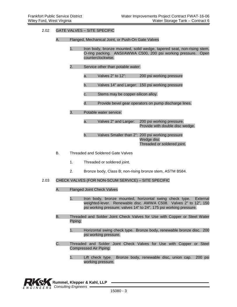
Frankfort Public Service District Water Improvements Project Contract FWAT-16-06 Wiley Ford, West Virginia Water Storage Tank – Contract 6
Rummel, Klepper & Kahl, LLP Consulting Engineers
15080 - 3
2.02 GATE VALVES – SITE SPECIFIC
A. Flanged, Mechanical Joint, or Push-On Gate Valves
1. Iron body, bronze mounted, solid wedge, tapered seat, non-rising stem, O-ring packing. ANSI/AWWA C500, 200 psi working pressure. Open counterclockwise.
2. Service other than potable water:
a. Valves 2" to 12": 200 psi working pressure
b. Valves 14" and Larger: 150 psi working pressure
c. Stems may be copper-silicon alloy.
d. Provide bevel gear operators on pump discharge lines.
3. Potable water service:
a. Valves 2" and Larger: 200 psi working pressure. Provide with double disc wedge.
b. Valves Smaller than 2": 200 psi working pressure Wedge disc Threaded or soldered joint.
B. Threaded and Soldered Gate Valves
1. Threaded or soldered joint.
2. Bronze body, Class B; non-rising bronze stem, ASTM B584.
2.03 CHECK VALVES (FOR NON-SCUM SERVICE) – SITE SPECIFIC
A. Flanged Joint Check Valves
1. Iron body, bronze mounted, horizontal swing check type. External weighted-lever. Renewable disc. AWWA C508. Valves 2" to 12", 150 psi working pressure; valves 14" to 24", 175 psi working pressure.
B. Threaded and Solder Joint Check Valves for Use with Copper or Steel Water Piping:
1. Horizontal swing check type. Bronze body, renewable bronze disc. 200 psi working pressure.
C. Threaded and Solder Joint Check Valves for Use with Copper or Steel Compressed Air Piping:
1. Lift check type. Bronze body, renewable disc, union cap. 200 psi working pressure.

Frankfort Public Service District Water Improvements Project Contract FWAT-16-06 Wiley Ford, West Virginia Water Storage Tank – Contract 6
Rummel, Klepper & Kahl, LLP Consulting Engineers
15080 - 4
D. Globe Style Silent Check Valves
1. Semi-steel body, bronze seat, bronze valve plug, stainless steel spring. Valve plug center-guided at both ends with a through integral shaft; helical or conical spring loaded. Replaceable seat and valve plug.
2. Flow area through body equal or greater than cross-sectional area of equivalent pipe size. 200 psi working pressure.
E. PVC Check Valves
1. Use on all plastic piping. Double union ball type. Viton seats. 150 psi working pressure.
F. Provide check valves designed so that all parts may be removed for inspection or replacement through the top of the valve with the valve in position.
2.04 PLUG VALVES
A. Plug valves shall be of the non-lubricated eccentric type with resilient faced plugs. All force main valves shall be furnished with mechanical joint connections, AWWA C111. Port areas of all plug valves shall be at least 100% of full pipe area.
B. Valve bodies shall be of ASTM A126, Class B cast iron in compliance with AWWA Standard C504, Section 5.4. All exposed nuts, bolts, springs, washers, etc. shall be stainless steel. Resilient plug facings shall be of neoprene, suitable for use with sewage.
C. Valves shall be furnished with corrosion resistant seats which comply with AWWA Standard C507, Section 7, Paragraph 7.2 and with AWWA Standard C504-74, Section 8, paragraphs 8.4, 8.5, 8.6, 8.6.2, 8.6.3., 8.6.4, 8.6.5, 8.6.6.
D. Valves shall be furnished with replaceable sleeve type bearings in the upper and lower journals. These bearings shall comply with AWWA Standard C507, Section 8, paragraphs 8.1, 8.3, and 8.5 and with AWWA Standard C504, Section 9.
E. Valve shaft seals shall comply with AWWA Standard C507-73, Section 10, and with AWWA C504, Section 10.
F. Valve pressure ratings shall be as follows and shall be established by hydrostatic tests as specified by ANSI Standard B16-1. Pressure rating shall be 175 psi. Valves shall be capable of providing drip-tight shutoff up to the full rating with pressure in each direction.
G. Valve operators shall be completely enclosed in an air, water, and oil-tight housing mounted directly on the valve and providing access to the valve stem packing. The housing shall comply with AWWA Standard C504, Sections 11.2.3 and 11.3. Both worm gear shafts and gear quadrants shall be furnished with replaceable sleeve type bearings the same as the valve bearings. Shaft seals shall be provided to seal all external shafting. All valves shall be completely sealed including the valve stem packing box. Open and closed stops shall be provided to comply with AWWA C504, Section 11.3.

Frankfort Public Service District Water Improvements Project Contract FWAT-16-06 Wiley Ford, West Virginia Water Storage Tank – Contract 6
Rummel, Klepper & Kahl, LLP Consulting Engineers
15080 - 5
H. Valves to be direct buried shall be provided with roadway valve boxes. Roadway valve boxes shall be cast iron and inside riser diameter of 5-1/4" and to be of the two-piece sliding adjustable type with drop cover marked for sewer service. Both the inside and outside of the valve box and cover shall be thoroughly cleaned and coated with asphaltum varnish, applied hot, before leaving the foundry. Extension stems with standard 2" square operating nuts shall be provided where depth from finished grade to valve operating nuts exceeds 5 feet. Extension stems shall be securely attached to the valve operating nut and shall be provided with means for centering the operating nut within the roadway valve box.
2.05 GLOBE VALVES
A. For use on air piping or for throttling service on water lines.
B. Bronze body rising stem, union bonnet, stainless steel plug type seat and disc. 200 psi working pressure.
2.06 BALL VALVES
A. Top entry, bronze body, chrome-plated brass ball, double seal TFE seat, TFE stem seal and bonnet O-ring. 200 psi working pressure. Flanged, threaded, or solder joint as applicable.
B. Iron body, (6" through 48" for water) 300 psi pressure, AWWA C507.
C. PVC ball valves: True union, double entry; Viton O-ring seals, self-lubricating Teflon seats. 150 psi working pressure.
2.07 BUTTERFLY VALVES (METAL BODY)
A. Rubber seated, tight-closing type designed, manufactured and tested in accordance with AWWA C504, latest revision.
B. Valve Body: Cast iron, ASTM A126, Class B.
C. Body Seat: 18-8 stainless steel.
D. Valve Vane: Ductile iron, A536, Grade 65-45-12, with rubber seat secured with a serrated 18-8 stainless steel clamp ring. Rubber seat shall be full 360o capable of replacement or adjustment without special tools.
E. Valve Shafts: 18-8 type 304 stainless steel with diameter equal or greater than as shown in AWWA C504.
F. 200 psi working pressure.
G. Furnish with valve position indicator.
H. Notch-plate lever throttling handles for valves 6" size and smaller.
I. Heavy-duty manual actuators for valves larger than 6" size.
1. Sealed and permanently lubricated. Fully supported, exert no thrust or load on valve shaft.

Frankfort Public Service District Water Improvements Project Contract FWAT-16-06 Wiley Ford, West Virginia Water Storage Tank – Contract 6
Rummel, Klepper & Kahl, LLP Consulting Engineers
15080 - 6
2. Vertical, right-angle or buried type as applicable. Crank handle, handwheel, or square nut operator as indicated on the drawings.
2.08 AIR RELEASE VALVE
Combination Air Valves: Consisting of an air release valve and an air and vacuum valve factory piped into a compact assembly. The combination assembly shall automatically release air, gas or vapor under system operating pressure and shall also allow air to re-enter the system during draining or when a vacuum occurs. Combination valve designs shall feature long bodies and float stem components so that the operating mechanisms are kept free from contact with the sewage during operation. Valve construction as follows:
1. Valve Bodies and Covers: Cast iron, ASTEM A 126, Class B.
2. Inlet Size: 2-inches.
3. Outlet Size: 1-inch, NPT.
4. Maximum Working Pressure: 150 psi.
5. Valve Discharge Orifice Seat, Mechanism and Valve Stem: Stainless Steel.
6. Valve Mechanism Lever Pins and Float: High strength stainless steel, ASTM A 240.
7. Valve Float Stem and Guide: Type 304 Stainless Steel.
8. Valve Float: Stainless Steel, ASTM A 240.
9. Valve Orifice Seat: Buna-N, Nitrile Rubber, ASTM SB 800.
10. Back flushing and Cleaning Accessories: Factory assembled to the combination valve and consisting of an inlet shut-off valve, a blow-off valve, a clear water inlet valve, section of rubber hose and quick disconnect couplings.
11. Acceptable Manufacturers:
a. Val-Matic Valve and Manufacturing Corp.; Model No. 802 BW. b. Or equal.
2.09 FLOW CONTROL ORIFICES
Threaded end inline orifices that maintain a fixed flow rate regardless of varying inlet pressure by means of a flexible orifice that varies its area inversely with pressure. 100 psi minimum working pressure.
2.10 CORPORATION STOPS
Brass or red-brass alloy body, ASTM B62. AWWA C800 threaded inlet end for tapping. Outlet end suitable for service pipe intended.

Frankfort Public Service District Water Improvements Project Contract FWAT-16-06 Wiley Ford, West Virginia Water Storage Tank – Contract 6
Rummel, Klepper & Kahl, LLP Consulting Engineers
15080 - 7
2.11 CURB STOP ASSEMBLY
A. Curb Stops
1. Brass or Red Brass alloy body conforming to ASTM B62.
2. Plug type valve.
3. Positive pressure sealing.
B. Curb Boxes and Covers
1. Cast iron body, extension type or Buffalo type.
2. Minneapolis or arch pattern base.
3. Lid with inscription “Water”, with pentagon plug.
2.12 SURGE RELIEF VALVE
A. External pilot operated. Cast iron globe body, bronze trim, leather packed.
1. Pilot adjustment range: 80-180 psi.
2. Flow range: 20-600 gpm.
2.13 AIR LINE SHUTOFF VALVES
A. For isolating small air supply branch and signal lines as shown in the contract drawings.
B. Toggle operated. Forged brass body, stainless steel stem, O-ring stem seal. Minimum 200 psi working pressure rated.
2.14 FLOOR TYPE TANK AND FOUNDATION PRESSURE RELIEF VALVES
A. Floor type hydrostatic pressure relief valve shall be designed for installing in the bottom of concrete tanks.
B. The assembly shall consist of three parts: cover, body and strainer; all of cast iron conforming to ASTM A126, Class B, designed so that neither the cover or strainer can become separated from the body of the valve, due to groundwater pressure around the tank; however, when necessary, both may be easily removed by turning them to the right or left to free them from locking lugs cast integrally on the inside of the body.
C. The seats shall be installed into grooves on underside of cover and top of body; seats shall be machined to form a non-corroding lead to lead contact when cover is in closed position.
2.15 WALL TYPE TANK PRESSURE RELIEF VALVES
A. The wall type hydrostatic pressure relief valve shall be suitable for sidewall
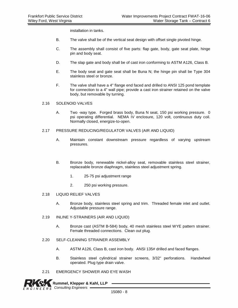
Frankfort Public Service District Water Improvements Project Contract FWAT-16-06 Wiley Ford, West Virginia Water Storage Tank – Contract 6
Rummel, Klepper & Kahl, LLP Consulting Engineers
15080 - 8
installation in tanks.
B. The valve shall be of the vertical seat design with offset single pivoted hinge.
C. The assembly shall consist of five parts: flap gate, body, gate seat plate, hinge pin and body seat.
D. The slap gate and body shall be of cast iron conforming to ASTM A126, Class B.
E. The body seat and gate seat shall be Buna N; the hinge pin shall be Type 304 stainless steel or bronze.
F. The valve shall have a 4" flange end faced and drilled to ANSI 125 pond template for connection to a 4" wall pipe; provide a cast iron strainer retained on the valve body, but removable by turning.
2.16 SOLENOID VALVES
A. Two -way type. Forged brass body, Buna N seat, 150 psi working pressure. 0 psi operating differential. NEMA IV enclosure, 120 volt, continuous duty coil. Normally closed, energize-to-open.
2.17 PRESSURE REDUCING/REGULATOR VALVES (AIR AND LIQUID)
A. Maintain constant downstream pressure regardless of varying upstream pressures.
B. Bronze body, renewable nickel-alloy seat, removable stainless steel strainer, replaceable bronze diaphragm, stainless steel adjustment spring.
1. 25-75 psi adjustment range
2. 250 psi working pressure.
2.18 LIQUID RELIEF VALVES
A. Bronze body, stainless steel spring and trim. Threaded female inlet and outlet. Adjustable pressure range.
2.19 INLINE Y-STRAINERS (AIR AND LIQUID)
A. Bronze cast (ASTM B-584) body, 40 mesh stainless steel WYE pattern strainer. Female threaded connections. Clean out plug.
2.20 SELF-CLEANING STRAINER ASSEMBLY
A. ASTM A126, Class B, cast iron body. ANSI 135# drilled and faced flanges.
B. Stainless steel cylindrical strainer screens, 3/32" perforations. Handwheel operated. Plug type drain valve.
2.21 EMERGENCY SHOWER AND EYE WASH

Frankfort Public Service District Water Improvements Project Contract FWAT-16-06 Wiley Ford, West Virginia Water Storage Tank – Contract 6
Rummel, Klepper & Kahl, LLP Consulting Engineers
15080 - 9
A. Exterior Installation
1. Freeze resistant, pedestal type with self-draining valves for shower and for eyewash.
2. Piping: Schedule 80, 1-1/4" galvanized steel.
3. Shower Head: Stainless steel with 1-1/4" NPT connection.
4. Shower Operation: Chest high push bars.
5. Eye Wash: Stainless steel bowl, actuated by push bar, ½” NPT connections.
B. Interior Installation
1. Free standing floor mounted drench shower and eye wash.
2. Shower shall have pull rod and handle with a stay open valve that is closed by pushing up on handle; shower head shall be ABS plastic.
3. Eye Wash: Hand operated, ABS bowl with soft stream heads.
4. Floor flange shall be minimum 9" diameter.
5. Pipe Support: Minimum 1-1/4" diameter, painted, galvanized pipe support.
2.22 FIRE HYDRANTS
A. Dry-barrel break-away type conforming to AWWA C502.
1. Bury Depth: 4'-6", or as indicated on the contract drawings.
2. Inlet connection: 6".
3. Valve opening: 5-1/4".
4. Mechanical joint or bell end.
5. Corrosion resistant bolts and nuts.
B. One pumper, two hose nozzles
1. Obtain thread type and size from local fire department.
2. Attach nozzle caps by separate chains.
2.23 YARD HYDRANTS
A. Self-draining, frost-proof. Cast brass, post type. Aluminum protective shield. 3/4" NPTF inlet; 3/4" HPT outlet connections. 3' depth of bury. T-handle or handwheel operator as indicated.

Frankfort Public Service District Water Improvements Project Contract FWAT-16-06 Wiley Ford, West Virginia Water Storage Tank – Contract 6
Rummel, Klepper & Kahl, LLP Consulting Engineers
15080 - 10
2.24 WALL HYDRANT (EXTERIOR)
A. Cast brass, non-freeze box type. Brass wall casting, polished face hinged locking cover. Renewable nylon valve seat. 3/4" NPTF inlet, 3/4" NPT outlet. T-handle or handwheel operator as indicated.
2.25 HOSE BIBBS (INTERIOR)
A. Cast brass with integral wall plate. Replaceable valve set, stainless steel shaft, nylon washer. 3/4" NPT outlet. Fixed operating wheel.
2.26 VALVE BOXES
A. Three-piece, cast iron, adjustable. 5-1/4" diameter. Heights as indicated.
2.27 PRESSURE GAUGES (LIQUID SERVICE)
A. Bronze bourdon tube type, brass socket. Stainless steel case. Acrylic window. Liquid filled.
B. 4-1/2" dial size. Stainless steel dial, black lines and numbers.
C. Pressure range as indicated. Graduations and figure intervals proportioned to range.
D. Polypropylene bushed, stainless steel rotary movement, micro-adjustable pointer. Minimum pressure stop, over-pressure protection. Adjustable zero set point adjustment screw which does not require removal of gauge case.
E. Accuracy to 1% of full-scale range.
F. 1/8" NPT bottom connection. Shutoff cock.
G. When indicated on the contract drawings, provide cadmium-plated diaphragm gauge seal; 316 ELC diaphragm, flushing connection, stopcock.
2.28 PRESSURE GAUGES (AIR SERVICE)
A. Bronze bourdon tube type, brass socket. Stainless steel case with blowout grommet.
B. 4-1/2" dial, white background, black lines and numbers.
C. Bronze brushed, rotary movement. Micro-adjustable pointer. Accuracy to 1% of full-scale range.
D. 1/8" bottom connection. Shutoff cock.
E. Pressure range as indicated shall cover 150% of operating range. Graduations and figure intervals proportioned to range.
2.29 HOSE COUPLINGS
A. Cam-locking quick-coupler. MPT coupler socket, FPT adapter plug, side levers. Stainless steel. Buna N gaskets. Meet MIL-C-27487 Specifications.

Frankfort Public Service District Water Improvements Project Contract FWAT-16-06 Wiley Ford, West Virginia Water Storage Tank – Contract 6
Rummel, Klepper & Kahl, LLP Consulting Engineers
15080 - 11
2.30 BACKFLOW PREVENTER
A. Reduced pressure principle type to protect against back-pressure backflow and back-siphonage. Size as indicated on the contract drawings.
B. Bronze body construction, stainless steel internal parts and flange bolts, tight seating rubber check valve assemblies. Provide complete with inlet Y-strainer and non-rising stem gate valves before and after the device.
C. NSF approved. Certified to meet or exceed the requirements of ASSE Standard 1013, AWWA C506, and USC Foundation for Cross-Connection Control Research.
2.31 WATER METERS
A. Displacement type meeting the requirements of AWWA C700, size of meters as specified on drawings.
B. Compound type meeting the requirements of AWWA C702, size as specified on drawings.2.32 TAPPING ACCESSORIES
A. Tapping Sleeves
1. Mechanical joint, or as indicated on the contract drawings.
2. 200 psi working pressure.
3. Outlet flange: ANSI B16.1, Class 125.
B. Tapping Valves
1. Iron body, bronze mounted, double disc with seat rings of larger diameter to permit entry of tapping machine cutters AWWA C500.
2. Inlet Flange, Class 125.
2.33 FLEXIBLE COUPLINGS AND REDUCERS
A. Flexible couplings and reducers are to be provided where shown on the drawings to compensate for misalignment, reduce noise and vibration, and alleviate stresses imparted to mating equipment.
B. Unless otherwise noted, couplings shall be of the double arch type capable of allowing up to 30o angular movement, 7/16" elongation, 7/8" compression, and 7/8" transverse movement. The couplings shall have a 26" Hg vacuum and a 150 psi pressure rating and shall have a maximum temperature rating of 212oF. The couplings shall be constructed of neoprene with multiple plies of nylon cord. Couplings shall have 150 lb. ANSI steel flanges that do not require the use of backup rings and shall be suitable for mating with Schedule 80 PVC flanges. Provide control units for each coupling to prevent damage due to excessive movement.
C. For flexible couplings used on chemical piping applications, submit manufacturer’s certification that the materials of construction of the coupling are suitable for continuous exposure to the chemical being transported.
2.34 FLOOR BOX
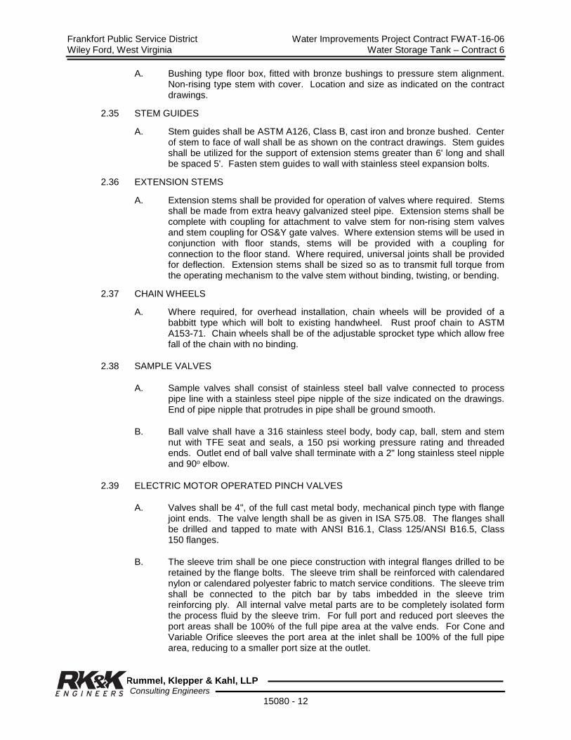
Frankfort Public Service District Water Improvements Project Contract FWAT-16-06 Wiley Ford, West Virginia Water Storage Tank – Contract 6
Rummel, Klepper & Kahl, LLP Consulting Engineers
15080 - 12
A. Bushing type floor box, fitted with bronze bushings to pressure stem alignment. Non-rising type stem with cover. Location and size as indicated on the contract drawings.
2.35 STEM GUIDES
A. Stem guides shall be ASTM A126, Class B, cast iron and bronze bushed. Center of stem to face of wall shall be as shown on the contract drawings. Stem guides shall be utilized for the support of extension stems greater than 6' long and shall be spaced 5'. Fasten stem guides to wall with stainless steel expansion bolts.
2.36 EXTENSION STEMS
A. Extension stems shall be provided for operation of valves where required. Stems shall be made from extra heavy galvanized steel pipe. Extension stems shall be complete with coupling for attachment to valve stem for non-rising stem valves and stem coupling for OS&Y gate valves. Where extension stems will be used in conjunction with floor stands, stems will be provided with a coupling for connection to the floor stand. Where required, universal joints shall be provided for deflection. Extension stems shall be sized so as to transmit full torque from the operating mechanism to the valve stem without binding, twisting, or bending.
2.37 CHAIN WHEELS
A. Where required, for overhead installation, chain wheels will be provided of a babbitt type which will bolt to existing handwheel. Rust proof chain to ASTM A153-71. Chain wheels shall be of the adjustable sprocket type which allow free fall of the chain with no binding.
2.38 SAMPLE VALVES
A. Sample valves shall consist of stainless steel ball valve connected to process pipe line with a stainless steel pipe nipple of the size indicated on the drawings. End of pipe nipple that protrudes in pipe shall be ground smooth.
B. Ball valve shall have a 316 stainless steel body, body cap, ball, stem and stem nut with TFE seat and seals, a 150 psi working pressure rating and threaded ends. Outlet end of ball valve shall terminate with a 2" long stainless steel nipple and 90o elbow.
2.39 ELECTRIC MOTOR OPERATED PINCH VALVES
A. Valves shall be 4", of the full cast metal body, mechanical pinch type with flange joint ends. The valve length shall be as given in ISA S75.08. The flanges shall be drilled and tapped to mate with ANSI B16.1, Class 125/ANSI B16.5, Class 150 flanges.
B. The sleeve trim shall be one piece construction with integral flanges drilled to be retained by the flange bolts. The sleeve trim shall be reinforced with calendared nylon or calendared polyester fabric to match service conditions. The sleeve trim shall be connected to the pitch bar by tabs imbedded in the sleeve trim reinforcing ply. All internal valve metal parts are to be completely isolated form the process fluid by the sleeve trim. For full port and reduced port sleeves the port areas shall be 100% of the full pipe area at the valve ends. For Cone and Variable Orifice sleeves the port area at the inlet shall be 100% of the full pipe area, reducing to a smaller port size at the outlet.

Frankfort Public Service District Water Improvements Project Contract FWAT-16-06 Wiley Ford, West Virginia Water Storage Tank – Contract 6
Rummel, Klepper & Kahl, LLP Consulting Engineers
15080 - 13
C. The solid steel pitch mechanism shall be single acting, closing the sleeve from the top only. The mechanism shall be supported in the valve body. There shall be no cast parts in the operating mechanism. The mechanism shall be connected to the electrically actuated actuator through an ACME threaded stem. The electric motor shall be as specified. The pinch mechanism shall be adjustable for stroke without removing the valve from the line. Valve shall be manufactured in the USA.
D. An electric motor rotates a threaded nut, pushing a threaded stem into the valve body, pinching the sleeve closed. Reversing the direction of the electric motor pulls the stem out of the valve body, opening the sleeve.
2.40 FLAP GATES (FLAP VALVES)
A. Gates shall be as sized in plans or specifications. Gate Assembly shall be material combination #4, as follows:
1. Seat and Cover shall be cast iron.
2. Sealing faces (seal) shall be neoprene.
3. Side wedge blocks (cover) shall be stainless steel.
4. Pivot lugs and links shall be cast iron.
5. Bushings shall be stainless steel.
6. Fasteners shall be stainless steel.
2.41 VENTED BALL VALVES (BLEACH BALL VALVES)
A. Vented Ball Valves shall be PVC.
B. Bleach ball valves must be on the True Union type with an energized seat that will concurrently provide automatic adjustment for wear and leak-free service at the lower pressure port. The ball must contain an adequate vent to the pressure port opposite of the downstream sealing port.
C. The manufacturer must complete all components prior to the factory assembly, test, and packaging of those valves. Modifications of assembled valves by any manufacturer or vendor is unacceptable. Also, the valves must be individually packaged with each carton label stating: Bleach ball valve, size, material and manufacturer.
D. Bleach ball valves must be permanently marked externally with: the word Bleach; two opposing directional arrows, one inscribed with Flow and the other with Vent.
PART 3 - EXECUTION
3.01 INSTALLATION
A. Install valves and accessories in accordance with the manufacturer’s instructions.
B. Inspect joint surfaces for structural soundness and thoroughly clean before installation.

Frankfort Public Service District Water Improvements Project Contract FWAT-16-06 Wiley Ford, West Virginia Water Storage Tank – Contract 6
Rummel, Klepper & Kahl, LLP Consulting Engineers
15080 - 14
C. Flap Gates shall be attached to pipe flanges mounted in the concrete wall. They are NOT to be attached directly to the concrete wall.
3.02 FIRE HYDRANTS
A. Install fire hydrants as shown on Standard Detail; provide support blocking and drainage gravel as shown; do not block drain hole.
B. Set hydrants plumb with pumper nozzle facing the roadway; set hydrants with centerline of pumper nozzle at least 18" above finished grade and the safety flange not more than 6" nor less than 2" above grade.
C. Paint hydrants in accordance with local color scheme.
D. After hydrostatic testing, flush hydrants and check for proper drainage.
3.03 ADJUSTMENT
A. Check and adjust valves and accessories for smooth operation.
END OF SECTION
The page intentionally left blank
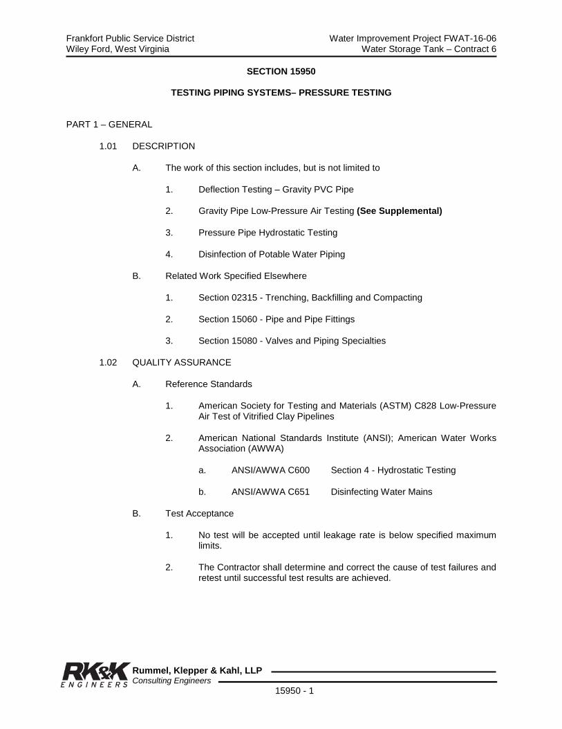
Frankfort Public Service District Water Improvement Project FWAT-16-06 Wiley Ford, West Virginia Water Storage Tank – Contract 6
Rummel, Klepper & Kahl, LLP Consulting Engineers
15950 - 1
SECTION 15950
TESTING PIPING SYSTEMS– PRESSURE TESTING PART 1 – GENERAL
1.01 DESCRIPTION
A. The work of this section includes, but is not limited to
1. Deflection Testing – Gravity PVC Pipe
2. Gravity Pipe Low-Pressure Air Testing (See Supplemental)
3. Pressure Pipe Hydrostatic Testing
4. Disinfection of Potable Water Piping
B. Related Work Specified Elsewhere
1. Section 02315 - Trenching, Backfilling and Compacting
2. Section 15060 - Pipe and Pipe Fittings
3. Section 15080 - Valves and Piping Specialties
1.02 QUALITY ASSURANCE
A. Reference Standards
1. American Society for Testing and Materials (ASTM) C828 Low-Pressure Air Test of Vitrified Clay Pipelines
2. American National Standards Institute (ANSI); American Water Works Association (AWWA)
a. ANSI/AWWA C600 Section 4 - Hydrostatic Testing
b. ANSI/AWWA C651 Disinfecting Water Mains
B. Test Acceptance
1. No test will be accepted until leakage rate is below specified maximum limits.
2. The Contractor shall determine and correct the cause of test failures and retest until successful test results are achieved.

Frankfort Public Service District Water Improvement Project FWAT-16-06 Wiley Ford, West Virginia Water Storage Tank – Contract 6
Rummel, Klepper & Kahl, LLP Consulting Engineers
15950 - 2
1.03 SUBMITTALS
A. Submit in accordance with Section 01300.
B. Submit the following prior to start of testing:
1. Test Procedures
2. List of Test Equipment
3. Testing Sequence Schedule
4. Certification of test pressure gauge calibration and accuracy.
5. Certification of composition of chlorination products.
PART 2 - PRODUCTS
2.01 DISINFECTION PRODUCTS
A. Liquid Chlorine: AWWA B301.
B. Calcium Hypochlorite and Sodium Hypochlorite: AWWA B300.
2.02 AIR TESTING EQUIPMENT
A. Air Compressor
B. Air Supply Lines
C. Test Connections
D. Pressure Regulator
E. Pressure Relief Valve
F. Pressure Gauge Calibrated to 0.1 lb/sq. inch.
2.03 HYDROSTATIC TEST EQUIPMENT
A. Hydro Pump
B. Pressure Hose
C. Test Connections
D. Pressure Relief Valve
E. Pressure Gauge Calibrated to 0.1 lb/sq. inch.
Frankfort Public Service District Water Improvement Project FWAT-16-06 Wiley Ford, West Virginia Water Storage Tank – Contract 6
Rummel, Klepper & Kahl, LLP Consulting Engineers
15950 - 3
PART 3 - EXECUTION
3.01 PREPARATION
A. Backfill trenches in accordance with Section 02315.
B. Provide concrete reaction support blocking, cured a minimum of 7 days, or a minimum of 3 days if high early strength concrete is used, for the pipeline to be tested.
C. Flush pipeline to remove debris; collect and dispose of flushing water and debris in a manner conforming to Regulatory Agency requirements.
3.02 DEFLECTION TESTING – GRAVITY PVC PIPE
The Contractor shall test PVC gravity sewer pipe for deflection in the presence of the Engineer. Deflection testing shall be performed after the pipe trench is completely backfilled, and before permanent trench paving or other surface restoration is done. Testing shall be accomplished using a PHOS Deflection Gauge as manufactured by PHOS, Inc., 4646 Carpinteria Avenue, Carpinteria, CA 93013. The gauge shall be attached to a line and pulled through the pipe manually. All pipe failing to meet the deflection limit of 5% or less shall be removed, replaced, and retested at the Contractor's expense.
3.03 AIR TESTING GRAVITY FLOW PIPELINES
All gravity lines shall be tested by the Contractor in a manner satisfactory to and witnessed by the Engineer. Reference is made to Section 15950 Appendix A – “UNI-B-6-98 – Recommended Practice for Low Pressure Air Testing of Installed Sewer Pipe” for additional details as approved by Engineer.
A. Contractor shall make visual tests as directed by Engineer in order to ascertain if joints are tight and sewer is laid to line and grade. A pressure test, using low-pressure air, shall then by conducted by the Contractor at his own expense.
B. Test each section of gravity flow pipeline between structures; plug all pipeline outlets; brace plugs to offset thrust.
C. Low pressure air shall be introduced into sealed line until internal pressure reaches 4 psig greater than average back pressure of any groundwater that may be over the pipe. At least two minutes shall be allowed for air pressure to stabilize. After stabilization period, pressure in the pipe shall be adjusted to a minimum of 3.5 psig plus average back pressure of any groundwater that may be over the pipe and air supply disconnected. The portion of line being tested shall be termed "acceptable” if the time required for pressure to decrease from 3.5 psig to 2.5 psig (plus average back pressure of any groundwater that may be over the pipe) is not less than the time shown in the Table I found in Section 15950 Appendix A.
D. If groundwater is present, determine its elevation above the springline of the pipe by means of a piezometric tube; for every foot of groundwater above the springline of the pipe, increase the starting test pressure reading by 0.43 psig; do not increase pressure above 10 psig.

Frankfort Public Service District Water Improvement Project FWAT-16-06 Wiley Ford, West Virginia Water Storage Tank – Contract 6
Rummel, Klepper & Kahl, LLP Consulting Engineers
15950 - 4
E. In no case should the starting test pressure exceed 9.0 psig. If the average vertical height of groundwater above the pipe invert is more than 12.7 feet, the section so submerged may be tested using 9.0 psig as the starting test pressure. The 9 psig limit is intended to further ensure workman safety and falls within the range of the pressure monitoring gauges normally used.
F. Allow air pressure to stabilize for at least five minutes; adjust pressure to 3.5 psig or to the increased test pressure as determined above if groundwater is present; start the test.
G. Table II contains specified minimum times required for a 0.5 psig pressure drop from a starting pressure of at least 3.5 psig greater than the average back pressure of any groundwater above the pipe’s invert. Both tables also include easy to use formulas for calculating required test times for various pipe sizes and odd lengths. Also, a zero pressure drop option is shown as a footnote to Table I and Table II. If there has been no leakage (zero psig drop) after one hour, the test section is accepted and the test is complete. A series of examples are provided in Section 15950a Supplemental to this recommended practice that demonstrates proper use of the tables. “Air Test Data Sheet” shall be completed by Contractor for each test.
H. Record the drop in pressure during the test period; if the air pressure has dropped more than 1.0 psig during the test period, the line is presumed to have failed; if the 1.0 psig air pressure drop has not occurred during the test period, the test shall be discontinued and the line will be accepted.
I. If line fails to meet requirement, Contractor shall, at his own expense, determine source of leakage. Contractor shall then repair or replace all defective material and/or workmanship and retest the line. Since the test must be conducted after backfilling, rectifications shall include re-excavation and backfill after repairs and/or replacement. All testing shall be performed on sewers before any road replacement of surface restoration operations are started.
J. The Contractor has the option to test the section in incremental stages until the leaks are isolated.
K. Testing Pipe Over 36" Diameter: Pipe larger than 36" diameter shall be subjected to a visual interior inspection.
3.04 HYDROSTATIC LEAKAGE TESTING PRESSURE FLOW PIPELINES
A. Hydrostatically test each section of pressure pipeline at the pressure designated on plans or specifications, based on the elevation of the lowest point in the pipeline corrected to the elevation of the test gauge, for a minimum period of two (2) hours or as approved by the Engineer.
B. Slowly fill the section with water, expelling air from pipeline at the high points; install corporation cocks at high points if necessary; after all air is expelled, close air vents and corporation cocks and raise the pressure to the specified test pressure.
C. Observe joints, fittings and valves under test, remove and renew cracked pipe, joints, fittings, and valves showing visible leakage; retest.
D. After visible deficiencies are corrected, continue testing at the same test pressure for an additional two hours to determine leakage rate.

Frankfort Public Service District Water Improvement Project FWAT-16-06 Wiley Ford, West Virginia Water Storage Tank – Contract 6
Rummel, Klepper & Kahl, LLP Consulting Engineers
15950 - 5
E. Maintain pressure within plus or minus 0.5 psig of test pressure.
F. Leakage is defined as the quantity of water supplied to the pipeline necessary to maintain test pressure during the period of the test and shall not exceed that determined by the following:
L = SD√P 133,222
Where: L = allowable leakage, in gallons per hour S = length of pipe tested, in feet D = nominal diameter of the pipe, in inches
P = average test pressure during the leakage test, in pounds per square inch (gauge).
ALLOWABLE LEAKAGE
W P D (gal/hr/1,000LF)
(psi) (psi) 2” 4” 6” 8” 10” 12”
60 100 0.150 0.300 0.450 0.601 0.751 0.901
70 105 0.154 0.308 0.462 0.615 0.769 0.923
80 120 0.164 0.329 0.493 0.658 0.822 0.987
90 135 0.174 0.349 0.523 0.698 0.872 1.047
100 150 0.184 0.368 0.552 0.736 0.919 1.103
110 165 0.193 0.386 0.579 0.771 0.964 1.157
120 180 0.201 0.403 0.604 0.806 1.007 1.209
130 195 0.210 0.419 0.629 0.839 1.048 1.258
140 210 0.218 0.435 0.653 0.870 1.088 1.306
150 225 0.225 0.450 0.676 0.901 1.126 1.351
160 240 0.233 0.465 0.698 0.930 1.163 1.396
170 255 0.240 0.480 0.719 0.959 1.199 1.439
180 270 0.247 0.493 0.740 0.987 1.234 1.480
190 285 0.253 0.507 0.760 1.014 1.267 1.521
200 300 0.260 0.520 0.780 1.040 1.300 1.560
210 315 0.266 0.533 0.799 1.066 1.332 1.599
220 330 0.273 0.546 0.818 1.091 1.364 1.637
230 345 0.279 0.558 0.837 1.116 1.394 1.673
240 360 0.285 0.570 0.855 1.140 1.424 1.709
250 375 0.291 0.582 0.872 1.163 1.454 1.745
W = Maximum Working Pressure within segment of tested pipe P = Test Pressure = 1.5 x W, but not less than 100 PSI D = Pipe Diameter (inches)
Example: 2,580 LF of 8” water line with a working pressure of 210 psi is to be tested for leakage.
Solution: The test pressure, P, to be used during leakage test is 1.5 x 210 = 315 psi. From the chart above, P = 315, the allowable leakage per 1,000 LF of 8” water main is 1.066 gallons per hour. Since 2,580 LF of pipe is being tested, the allowable leakage is 2,580 / 1,000 x 1.066 = 2.7503 gal/hr.
For a 2 hour test, the allowable leakage would be 2 x 2.7503 = 5.5066 gallons. If 5.5 (5 ½) gallons or less must be added to the water line at end of 2 hours to bring the test pressure to 315 psi, the line has passed.

Frankfort Public Service District Water Improvement Project FWAT-16-06 Wiley Ford, West Virginia Water Storage Tank – Contract 6
Rummel, Klepper & Kahl, LLP Consulting Engineers
15950 - 6
G. If the test of the pipeline indicates leakage greater than that allowed, locate the source of the leakage, make connections and retest until leakage is within the allowable limits.
H. Correct visible leaks regardless of the amount of leakage.
3.05 HYDROSTATIC TESTING PRESSURE PIPING SYSTEMS
A. Applicable to chlorine solution piping system, potable water pressure system, chemical feed systems, and all process piping systems within the wastewater treatment plant buildings.
B. Fill entire systems with water and vent air from the system at least 24 hours before the actual test pressure is applied.
C. Apply the required test pressure when the water and average ambient temperatures are approximately equal and constant.
D. Test piping at pressures listed on Yard Piping Plan; avoid excessive pressure on safety devices and mechanical seals.
E. Maintain test pressure for a minimum of 2 hours without drop after the force pump has been disconnected.
F. Visually inspect joints, fittings, and valves while pipe is under test pressure.
G. Correct all visible leaks and retest as often as necessary until satisfactory results are achieved.
3.06 DISINFECTION OF POTABLE WATER PIPING
A. Conduct disinfection of potable water system after completion of satisfactory pressure and leakage testing.
B. Disinfect in accordance with recommended practice established by AWWA C651.
C. Preliminary Flushing
1. Flush the line at a rate of flow of 2.5 feet per second for a period of 15 minutes; refer to table at end of this Section for the rates of flow to produce a velocity of 2.5 fps.
2. Provide and install one hydraulically propelled polyurethane “pig” in each line 4 inches or greater in diameter prior to flushing and flush the “pig” through the line; pig shall have the ability to negotiate fabricated mitered bends and short radius elbows and pass through tees, crosses and multi-dimensional sizes of pipe and valves.
3. Dispose of flushing water in compliance with Federal, State and Local laws.
D. Chlorine Form
1. The chlorine form to be applied to the system shall be either liquid chlorine, calcium hypochlorite or sodium hypochlorite.

Frankfort Public Service District Water Improvement Project FWAT-16-06 Wiley Ford, West Virginia Water Storage Tank – Contract 6
Rummel, Klepper & Kahl, LLP Consulting Engineers
15950 - 7
2. The Engineer’s written approval of the chlorine form to be used is required.
E. Chlorine Application
1. Introduce the chlorine to the system by use of the continuous feed method.
2. Feed water and chlorine to the line at a constant rate so that chlorine concentration in the pipe is a minimum of 50 mg/L available chlorine.
3. Continue chlorine applications until the entire system is filled with the chlorine solution.
4. During the 24-hour treatment, operate all valves, stops, and hydrants in the section treated.
5. At the completion of the 24-hour treatment, the water shall contain a minimum of 25 mg/L chlorine throughout the line.
6. Repeat the disinfection process until the specified minimum available chlorine is present at the end of the treatment sequence.
F. Final Flushing
1. Flush the heavily chlorinated water from the system under treatment until the chlorine concentration in the water leaving the system is less than 1 mg/L.
2. Comply with federal, state and local laws when discharging the flushed disinfecting chlorine solution.
G. Bacteriological Testing
1. After final flushing is completed and before the water main is placed in service, test the line for bacteriologic quality.
2. Collect a minimum of 2 samples 24 hours apart in sterile bottles treated with sodium thiosulfate (metering requirements of the WV Bureau of Public Health.
3. Provide bacteriological test reports to the Owner and the Engineer; failure to meet State Health Standard requirements will be cause for the Contractor to re-chlorinate and retest the system, at no additional cost to the Owner.
TABLE
Required Flow to Flush Pipelines *(a)
Pipe Diameter (Inches)
Flow Required to Produce 2.5 fps Velocity in gpm
Size of Tap on Main (inches) *(b)
Hydrant Outlets Size Number (Inches)
4 100 15/16 1 2-1/2
6 220 1-3/8 1 2-1/2
8 390 1-7/8 1 2-1/2
10 610 2-5/16 1 2-1/2
12 880 2-13/16 1 2-1/2
*(a) With a 40 psi pressure in main, hydrant flowing to atmosphere, a 2-1/2" hydrant outlet will discharge approximately 1,000 gpm.
*(b) Size of tap on main with no length of discharge piping.
END OF SECTION

Frankfort Public Service District Water Improvement Project FWAT-16-06 Wiley Ford, West Virginia Water Storage Tank – Contract 6
Rummel, Klepper & Kahl, LLP Consulting Engineers
15950 - 8
THIS PAGE LEFT BLANK


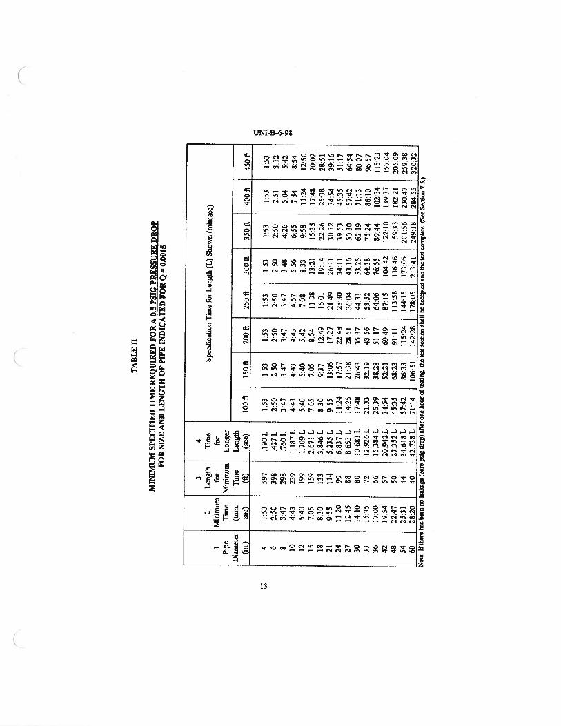

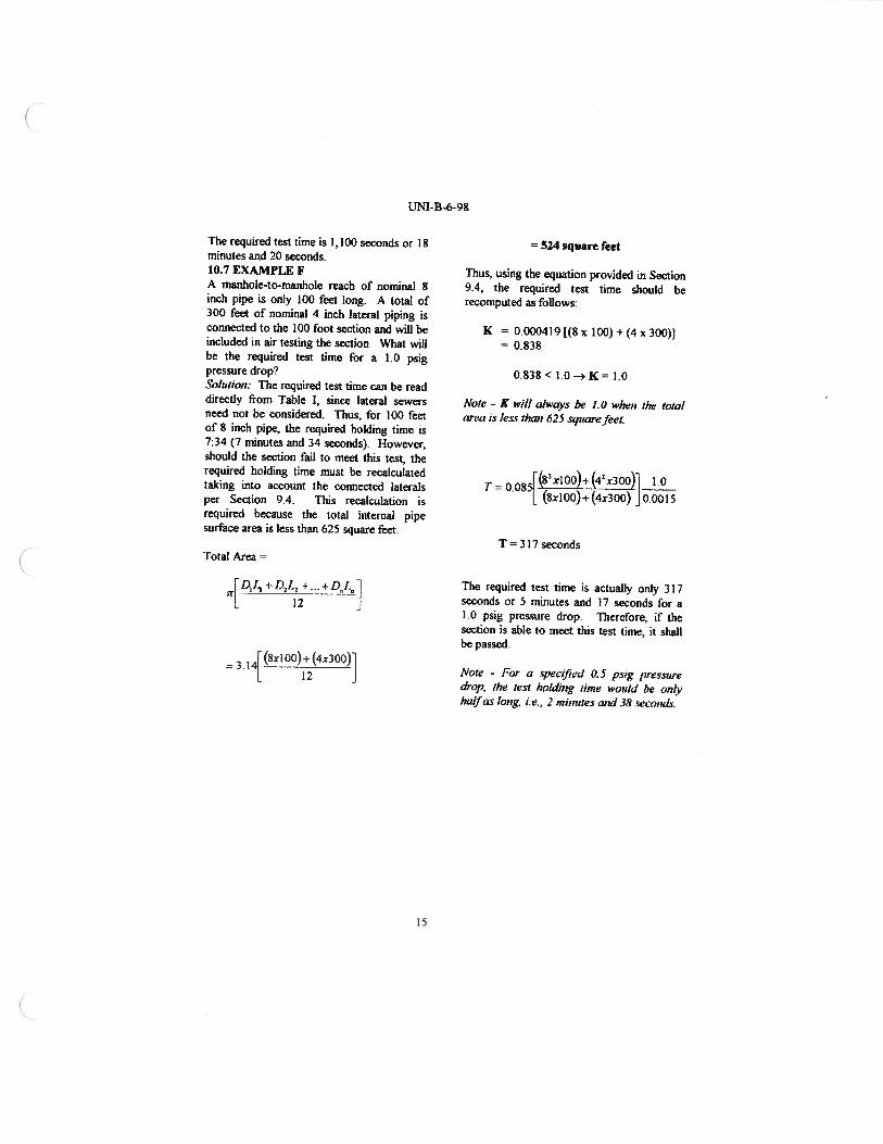


Frankfort Public Service District Water Improvement Project FWAT-16-06 Wiley Ford, West Virginia Water Storage Tank - Contract 06
Rummel, Klepper & Kahl, LLP Consulting Engineers
APPENDIX A
PERMITS

Frankfort Public Service District Water Improvement Project FWAT-16-06 Wiley Ford, West Virginia Water Storage Tank - Contract 06
Rummel, Klepper & Kahl, LLP Consulting Engineers
THIS PAGE LEFT BLANK

Frankfort Public Service District Water Improvement Project FWAT-16-06 Wiley Ford, West Virginia Middle Ridge Water Tank - Contract 06
Rummel, Klepper & Kahl, LLP Consulting Engineers
WV BUREAU FOR PUBLIC
HEALTH
WATER PERMIT
Frankfort Public Service District Water Improvement Project FWAT-16-06 Wiley Ford, West Virginia Middle Ridge Water Tank - Contract 06
Rummel, Klepper & Kahl, LLP Consulting Engineers
THIS PAGE LEFT BLANK


Frankfort Public Service District Water Improvement Project FWAT-16-06 Wiley Ford, West Virginia Middle Ridge Water Tank - Contract 06
Rummel, Klepper & Kahl, LLP Consulting Engineers
WV/NPDES GENERAL PERMIT
CONSTRUCTION STORMWATER
(PENDING)

Frankfort Public Service District Water Improvement Project FWAT-16-06 Wiley Ford, West Virginia Middle Ridge Water Tank - Contract 06
Rummel, Klepper & Kahl, LLP Consulting Engineers
THIS PAGE LEFT BLANK
Frankfort Public Service District Water Improvement Project FWAT-16-06 Wiley Ford, West Virginia Middle Ridge Water Tank - Contract 06
Rummel, Klepper & Kahl, LLP Consulting Engineers
THIS PAGE LEFT BLANK
Frankfort Public Service District Water Improvement Project FWAT-16-06 Wiley Ford, West Virginia Middle Ridge Water Tank - Contract 06
Rummel, Klepper & Kahl, LLP Consulting Engineers
WV ARMY CORP ENGINEERS NATIONWIDE – 12 PERMIT

Frankfort Public Service District Water Improvement Project FWAT-16-06 Wiley Ford, West Virginia Middle Ridge Water Tank - Contract 06
Rummel, Klepper & Kahl, LLP Consulting Engineers
THIS PAGE LEFT BLANK


Frankfort Public Service District Water Improvement Project FWAT-16-06 Wiley Ford, West Virginia Middle Ridge Water Tank - Contract 06
Rummel, Klepper & Kahl, LLP Consulting Engineers
WV DIVISION OF HIGHWAYS
ENCROACHMENT PERMIT (PENDING)

Frankfort Public Service District Water Improvement Project FWAT-16-06 Wiley Ford, West Virginia Middle Ridge Water Tank - Contract 06
Rummel, Klepper & Kahl, LLP Consulting Engineers
THIS PAGE LEFT BLANK


