48
AnyFeeder Integration Guide AnyFeeder SXM100/140 AnyFeeder SX240/340 R262I-E-01

AnyFeeder
Integration Guide
AnyFeeder SXM100/140 AnyFeeder SX240/340
R262I-E-01

The information contained herein is the property of Omron Adept Technologies, Inc., and shall not bereproduced in whole or in part without prior written approval of Omron Adept Technologies, Inc. Theinformation herein is subject to change without notice and should not be construed as a commitment byOmron Adept Technologies, Inc. This manual is periodically reviewed and revised.
Omron Adept Technologies, Inc., assumes no responsibility for any errors or omissions in this document.Critical evaluation of this manual by the user is welcomed. Your comments assist us in preparation offuture documentation.
Please email your comments to: [email protected].
Copyright 2017 by Omron Adept Technologies, Inc. All rights are reserved.
Any trademarks from other companies used in this publication are the property of those respective com-panies.

Table of Contents
Chapter 1: Introduction 5
1.1 Intended Audience 51.2 Prerequisites 5AnyFeeder Components 6
1.3 How Can I Get Help? 7Websites 7Related Manuals 7Support 8
Chapter 2: Safety 9
2.1 Warnings, Cautions, and Precautions 92.2 Safety Precautions 102.3 What to Do in an Emergency Situation 102.4 Additional Safety Information 10Robot Safety Guide 10
Chapter 3: Component Setup 11
3.1 Robot System with AnyFeeder 113.2 Basic Components 123.3 Power Required 123.4 Data and Air Required 133.5 Camera AnyFeeder Setup 133.6 AnyFeederInterface Panel LEDs 15
Chapter 4: System Installation 17
4.1 System Cables, without SmartController 17List of Cables and Parts 18Cable Installation Overview 19Optional Cables 20
4.2 System Cables, with SmartController 21Installing a SmartController Motion Controller 21List of Cables and Parts 22Cable Installation Overview 23Optional Cables 24
4.3 AnyFeeder Connections 24Electrical Connectors on Interface Panel 24Installing Cables and Power 25RS-232 Cable Installation 26
AnyFeeder Integration Guide - Page 3
Table of Contents
Connecting the Servo Power Cable 26Installing the Pneumatic Line 28
Chapter 5: Configuration with ACE Software 29
5.1 ACE Software 295.2 ACE Sight Overview 29Initial Configuration 29
5.3 Pick and Place Sequence Wizard 30Safe and Picture-taking Positions 31Create Feeder 31Teach Pick for Arm- or Fixed-Mount Camera 32Teach Place Position 36
Chapter 6: Fine-Tuning 37
6.1 Configuration Refinement 376.2 Multiple Locator Models 37Other ACE Sight Vision Tools 44
Chapter 7: Revision History 47
AnyFeeder Integration Guide - Page 4

Chapter 1: Introduction
This manual describes the steps for incorporating an AnyFeeder into your robot system.
The AnyFeeder, combined with a camera, performs flexible feeding so that a robot can pickand place products. ACE software provides interview wizards, so you can have a fully-integ-rated system with robot, controls and vision guidance set up quickly, with object finding fea-tures, automated calibration, and a tool library.
Changing the parts that the AnyFeeder system is handling is accomplished by adding a newLocator Model to the ACE Sight application. If the new parts are a different thickness thanyour existing Models, you will also have to teach a new height from the surface for picking.
1.1 Intended Audience
This guide is intended for an end-user or integrator who is familiar with Omron Adept robotsand the AnyFeeder. It is assumed that you have already selected the robot and AnyFeeder mod-els that you are going to use, as well as the accessories that will be used with those devices,such as the type of backlight, if any, for the AnyFeeder. It is also assumed that you have aworking knowledge of ACE.
1.2 Prerequisites
l Omron Adept Technologies, Inc. robot
Either a robot with an eAIB or eMB-40/60R, or one that uses a SmartController EX (run-ning eV+).
l AnyFeeder
The supported models are SXM100, SXM140, SX240, and SX340.
l Rigid mounting surfaces for the robot and AnyFeeder
l High-resolution camera with lens
o Camera-mounting structure
o Camera interface cables
l Keyboard, Monitor, and Mouse(for interfacing with and programming the robot and vision system)
l SmartController EX (option, recommended for Quattro)
l SmartVision MX industrial computer
l Power Supplies for AnyFeeder, SmartController EX, robot, and SmartVision MX
This guide assumes that the robot and any related equipment, such as a conveyor, areinstalled and functional. This guide focuses on the introduction of an AnyFeeder into that sys-tem.
AnyFeeder Integration Guide - Page 5

Chapter 1: Introduction
AnyFeeder Components
SX240 andSX340 only
Bulk container
Feed platform
Feed platformfront panel
Interface panelPneumaticconnector
Handles
Mounting rail
Retainer
Purge flap
Backlight(under feedplatform)
Figure 1-1. AnyFeeder Parts, Model SX240 shown
There are four different AnyFeeder-models supported:
l AnyFeeder SXM100
l AnyFeeder SXM140
l AnyFeeder SX240
l AnyFeeder SX340
In most respects, the feeders are similar enough that they will be covered together.In areas where there are significant differences, information is given for each model or presen-ted separately as appropriate.
Your AnyFeeder package includes:
l AnyFeeder Feeder
l 24 VDC Power Cable, 5 m (also called servo cable)
l RS232 Cable, 4.5 m
l User’s Guide
AnyFeeder Integration Guide - Page 6

Chapter 1: Introduction
You will need to add:
l A Feed Surface
These come in various colors and textures, depending on the parts to be handled.
You may want to add:
l Backlight
This can be red or infra-red.
1.3 How Can I Get Help?
Websites
Refer to one of the following corporate websites:
http://www.ia.omron.com
and
http://www.adept.com
Related Manuals
The following table lists manuals related to this document.
To ensure system safety, make sure to always read and heed the information provided in allSafety Precautions, Precautions for Safe Use, and Precaution for Correct Use of manuals foreach device which is used in the system.
Table 1-1. Related Manuals
Manual Title Description
AnyFeeder User's Guide Instructions for installation and con-figuration of an AnyFeeder.
Your robot user’s guide Instructions for installation, use, andmaintenance of your robot.
Robot Safety Guide Contains safety information for ourrobots.
SmartController User's Guide Instructions for use of the optionalSmartController motion controller.
SmartVision MX User's Guide Instructions for use of the SmartVisionMX industrial PC.
ACE User’s Guide Describes the installation and use of ACEsoftware.
ACE Sight Reference Guide Describes V+ and microV+ keywords andproperties.Also describes framework and tool prop-erties.
AnyFeeder Integration Guide - Page 7

Chapter 1: Introduction
Support
If, after reading this manual, you are having problems with your AnyFeeder, contact your localOmron Support.
AnyFeeder Integration Guide - Page 8

Chapter 2: Safety
2.1 Warnings, Cautions, and Precautions
There are six levels of special alert notation used in our manuals.In descending order of importance, they are:
DANGER: This indicates an imminently hazardous electrical situation which,if not avoided, will result in death or serious injury.
DANGER: This indicates an imminently hazardous situation which, if notavoided, will result in death or serious injury.
WARNING: This indicates a potentially hazardous electrical situation which,if not avoided, could result in injury or major damage to the equipment.
WARNING: This indicates a potentially hazardous situation which, if notavoided, could result in injury or major damage to the equipment.
CAUTION: This indicates a situation which, if not avoided, could result indamage to the equipment.
Precautions for Safe Use: This indicates precautions on what to do and whatnot to do to ensure using the product safely.
AnyFeeder Integration Guide - Page 9

Chapter 2: Safety
2.2 Safety Precautions
WARNING: An AnyFeeder or industrial robot can cause personal injury ordamage to itself and other equipment if the following safety precautions are notobserved:
l All personnel who install, operate, program, or maintain the system must read thisguide, the AnyFeeder User’s Guide, the robot user’s guide, and the Robot Safety Guide,and complete an appropriate Omron training course for their responsibilities in regardto the feeder.
l All personnel who install the feeder system must read this guide, read the Robot SafetyGuide, and must comply with all local and national safety regulations for the location inwhich the feeder system is installed.
l Power to the feeder and robot must be locked out and tagged out before any main-tenance is performed.
l Understand the specifications of the equipment that is used in the system. Allow somemargin for ratings and performance.
l Provide safety measures, such as installing a safety circuit, in order to ensure safety andminimize the risk of emergency situations.
2.3 What to Do in an Emergency Situation
Press any E-Stop button (a red push-button on a yellow background) on any robot being usedwith the feeder, power-down the feeder, and then follow the internal procedures of your com-pany or organization for an emergency situation. If a fire occurs, use CO2 to extinguish the fire.
2.4 Additional Safety Information
We provides other sources for more safety information:
Robot Safety Guide
The Robot Safety Guide provides detailed information on safety for our robots.It also gives resources for more information on relevant standards. It ships with each robot.
AnyFeeder Integration Guide - Page 10
Chapter 3: Component Setup
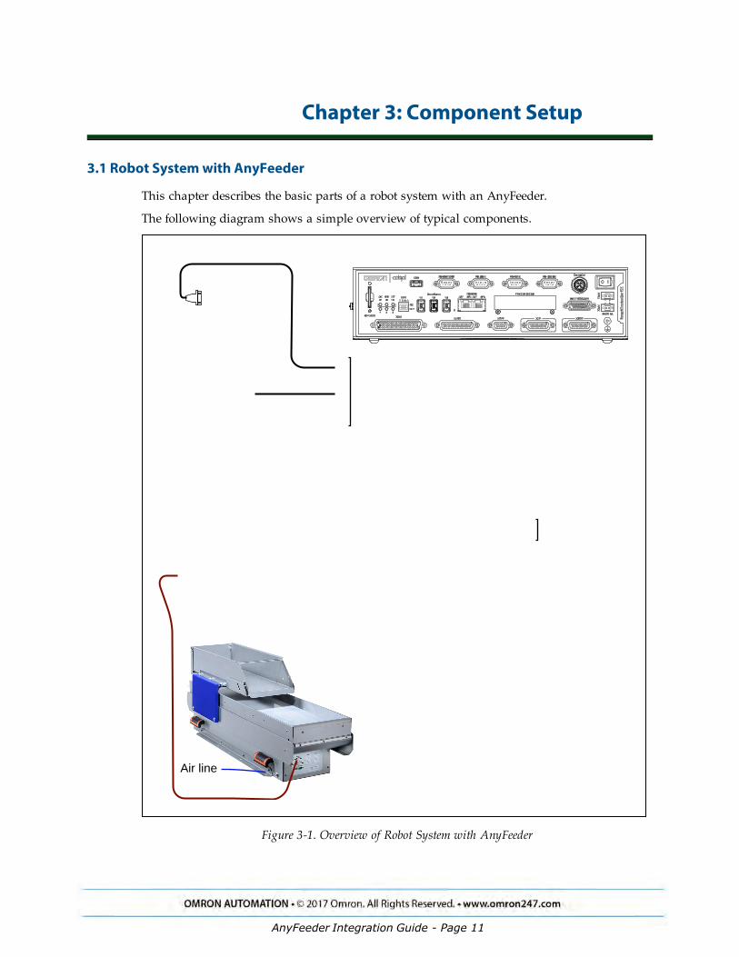
3.1 Robot System with AnyFeeder
This chapter describes the basic parts of a robot system with an AnyFeeder.
The following diagram shows a simple overview of typical components.
Air line
9
Belt orTarget
Front Panel
RobotInterface Panel
T20 Pendant (option)
RS232
All to SmartController EX, if available, orto Robot Interface Panel otherwise
SmartVision MXrunning ACE
CameraAnyFeeder
Robot, eCobra600 shown
SmartController EX
Figure 3-1. Overview of Robot System with AnyFeeder
AnyFeeder Integration Guide - Page 11

Chapter 3: Component Setup
NOTE: More detailed figures, showing connectivity, are shown in System Install-ation on page 17.
3.2 Basic Components
l Robot
All Omron Adept robots running eV+ are supported.With an eCobra, the Pro version is required for active conveyor tracking, and either theStandard or Pro version is required for use of ACE Sight.
l Front Panel
l T20 Pendant - optional
l SmartVision MX
This comes pre-loaded with ACE. It includes the USB license dongle.
l SmartController EX - optional
This is recommended when using a Quattro with an AnyFeeder.
l AnyFeeder
The supported models are SXM100, SXM140, SX240, and SX340.
l Camera
If you are using an IR backlight, we recommend you also use an IR lens filter. For Baslercameras sold by Omron Adept Technologies, Inc., the filter is PN: 09324-000.
l Conveyor or other target
3.3 Power Required
l Robot - according to robot user’s guide
This is typically both VAC and 24 VDC.
l AnyFeeder - from user-supplied power supply
24 VDC, 10 A
l Camera - PoE or separate, user-supplied power
l SmartController (option) - from user-supplied power supply
24 VDC, 5 A - this can share a 6 A power supply with the robot
l SmartVision MX - from user-supplied power supply
24 VDC, 6 A
AnyFeeder Integration Guide - Page 12

Chapter 3: Component Setup
3.4 Data and Air Required
l SmartVision MX to SmartController EX if present, otherwise to eAIB or eMB-40/60R
l AnyFeeder to SmartVision MX (RS-232)
l Camera to SmartVision MX
l T20 Pendant (option) to SmartController EX if present, or else eAIB or eMB-40/60R
l Front Panel to SmartController EX if present, or else eAIB or eMB-40/60R
l Pneumatic, to the SX240 and SX340 model AnyFeeders.
3.5 Camera AnyFeeder Setup
The camera’s field-of-view needs to cover the entire pick window of the AnyFeeder‘s feed sur-face.
The AnyFeeder must be mounted such that the robot can reach any part on the pick windowwithout touching the sides of the AnyFeeder, and without any joints exceeding their limits.
AnyFeeder SXM100
Chipsizeinches
FOVmm
Resolutionmm/Pixel
DistanceFOV
Lens mm
Lensmm
LensP/N
IR FilterP/N
DotMatrix
1/1.8 110x148 0.092 550 25 09323-000
09324-000
4 mm
1/1.8 110x148 0.092 760 35 09323-100
09324-000
4 mm
1/1.8 110x148 0.092 1090 50 Custom Custom 4 mm
1 140x140 0.068 655 50 Custom Custom 2 mm
AnyFeeder SXM140
Chipsizeinches
FOVmm
Resolutionmm/Pixel
DistanceFOV
Lens mm
Lensmm
LensP/N
IR FilterP/N
DotMatrix
1/1.8 150x202 0.125 730 25 09323-000
09324-000
4 mm
1/1.8 150x202 0.125 1025 35 09323-100
09324-000
4 mm
1/1.8 150x202 0.125 1460 50 Custom Custom 4 mm
1 200x200 0.098 650 35 Custom Custom 4 mm
1 200x200 0.098 935 50 Custom Custom 4 mm
AnyFeeder Integration Guide - Page 13

Chapter 3: Component Setup
AnyFeeder SX240
Chipsizeinches
FOVmm
Resolutionmm/Pixel
DistanceFOV
Lens mm
Lensmm
LensP/N
IR FilterP/N
DotMatrix
1/1.8 250x337 0.201 770 16 09322-000
09324-000
8 mm
1/1.8 250x337 0.201 1200 25 09323-000
09324-000
8 mm
1/1.8 250x337 0.201 1680 35 09323-100
09324-000
8 mm
1 330x330 0.161 485 16 Custom Custom 4 mm
1 330x330 0.161 760 25 Custom Custom 4 mm
1 330x330 0.161 1055 35 Custom Custom 4 mm
1 330x330 0.161 1510 50 Custom Custom 4 mm
AnyFeeder SX340
Chipsizeinches
FOVmm
Resolutionmm/Pixel
DistanceFOV
Lens mm
Lensmm
LensP/N
IR FilterP/N
DotMatrix
1/1.8 350x472 0.292 1070 16 09322-000
09324-000
10mm
1/1.8 350x472 0.292 1670 25 09323-000
09324-000
10mm
1/1.8 350x472 0.292 2340 35 09323-100
09324-000
10mm
1 470x470 0.230 760 25 Custom Custom 8 mm
1 470x470 0.230 1060 35 Custom Custom 8 mm
1 470x470 0.230 1510 50 Custom Custom 8 mm
AnyFeeder Integration Guide - Page 14

Chapter 3: Component Setup
3.6 AnyFeederInterface Panel LEDs
ElectricalConnectors
Status LEDs for Digital I/O
Status LED for High Power
Figure 3-2. Interface Panel on AnyFeeder
AnyFeeder Integration Guide - Page 15


Chapter 4: System Installation
4.1 System Cables, without SmartController
The letters in the following figure correspond to the letters in the table of cables and parts. Thenumbers correspond to the steps in the cable installation overview table. The tables are on thepages following the figure.
DC
IN
24 VGND
AC
200 -240 V
Ø1 XB
ELT
IO
XIO Servo
ENETENETXSYSTEM
9
Belt orTarget
24 VDC, 6 APower Supply
200-240 VAC10 A, single-phase AC Power
Cable
DC Power Cable
Front Panel Cable
Front Panel
T20 Adapter Cable
XMCP Jumper Plug
XMCP
XFP
XUSR
XUSR Jumper Plug
eAIBXSYSTEM Cable
eAIB or eMB-40/60RInterface Panel
XUSR for: - User E-Stop/Safety Gate- Muted Safety Gate
The Jumper Plug is required if neither of these is used
T20 Bypass Plug
T20 Pendant (option) Either T20 Pendant,T20 Bypass Plug, or XMCP Jumper Plug must be used
Ethernet to eAIBor eMB-40/60R
FP Jumper PlugEither Front Panel orFP plug must be used
Ethernet to SmartVision MX
User-suppliedSwitch (option)
RS232
eAIB Interface Panel
RS232
24 VDC, 6 APower Supply
SmartVision MX
DC Power Cable
Camera
Connectionson back side
AnyFeederSX240 shown
Robot, eCobra600 shown
9
A
L
M
Q
N2
R S
V U
T
M
GH
J
B
ED
F
C
K
P
DC Servo Cable
N1
7a 10
8
1
6
7
9
8
11
3
4a
4
3a
4a
4
2
3
2a
8 mm ODAir line X 12
24 VDC10 APowerSupply
Figure 4-1. System Cable Diagram for AnyFeeder, eCobra with Pendant Shown
AnyFeeder Integration Guide - Page 17

Chapter 4: System Installation
The pendant is an option, and may not be present in your system. This figure includes theoptional T20 pendant.
List of Cables and Parts
Open the Accessory box and locate the eAIB XSYSTEM cable. Connect the cables and peri-pherals as shown in the preceding figure. Parts and steps are covered in the following twotables.
Part Cable and Parts List Part # Part of: Notes
A eAIB XSYSTEM Cable Assembly 13323-000 standard, eAIB
B User E-Stop, Safety Gate n/a n/a user-supplied
C XUSR Jumper Plug 04736-000 13323-000 standard, eAIB
D Front Panel 90356-10358 standard
E Front Panel Cable 10356-10500 90356-10358 standard
F Front Panel Jumper Plug 10053-000 13323-000 standard, eAIB
G XMCP Jumper Plug 04737-000 13323-000 standard, eAIB
H T20 Bypass Plug 10048-000 10055-000 standard, T20
J T20 Adapter Cable 10051-003 10055-000 standard, T20
K T20 Pendant (option) 10055-000 option
L AC Power Cable 04118-000 90565-010 or user-supplied
M 24 VDC Power Cable 04120-000 90565-010 or user-supplied
N1 24 VDC, 6 A Power Supply 04536-000a or user-supplied
N2 24 VDC, 6 A Power Supply 04536-000 90565-010 or user-supplied
P RS232 Cable n/a AnyFeeder
Q Ethernet Cable -> eAIB or eMB-40/60R
n/a n/a user-supplied
R Ethernet Cable -> SmartVision MX n/a n/a user-supplied
S Ethernet switch (optional) n/a n/a user-supplied
T Camera and cable n/a n/a user-supplied
U AnyFeeder Servo Cable n/a AnyFeeder
V 24 VDC, 10 A Power Supply n/a n/a user-supplied
X 8 mm OD Air Line n/a n/a user-supplied
a: Only one 04536-000 power supply comes with the 90565-010 kit.
The XUSR, XMCP, and XFP jumpers intentionally bypass safety connections so you can testthe system functionality during setup.
AnyFeeder Integration Guide - Page 18
Chapter 4: System Installation
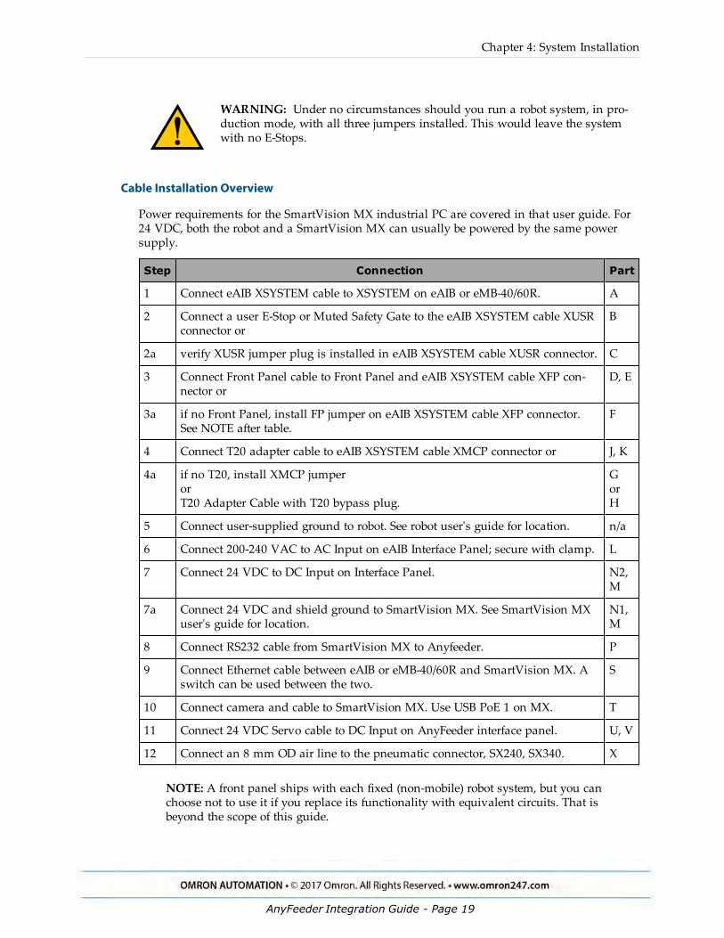
WARNING: Under no circumstances should you run a robot system, in pro-duction mode, with all three jumpers installed. This would leave the systemwith no E-Stops.
Cable Installation Overview
Power requirements for the SmartVision MX industrial PC are covered in that user guide. For24 VDC, both the robot and a SmartVision MX can usually be powered by the same powersupply.
Step Connection Part
1 Connect eAIB XSYSTEM cable to XSYSTEM on eAIB or eMB-40/60R. A
2 Connect a user E-Stop or Muted Safety Gate to the eAIB XSYSTEM cable XUSRconnector or
B
2a verify XUSR jumper plug is installed in eAIB XSYSTEM cable XUSR connector. C
3 Connect Front Panel cable to Front Panel and eAIB XSYSTEM cable XFP con-nector or
D, E
3a if no Front Panel, install FP jumper on eAIB XSYSTEM cable XFP connector.See NOTE after table.
F
4 Connect T20 adapter cable to eAIB XSYSTEM cable XMCP connector or J, K
4a if no T20, install XMCP jumperorT20 Adapter Cable with T20 bypass plug.
GorH
5 Connect user-supplied ground to robot. See robot user's guide for location. n/a
6 Connect 200-240 VAC to AC Input on eAIB Interface Panel; secure with clamp. L
7 Connect 24 VDC to DC Input on Interface Panel. N2,M
7a Connect 24 VDC and shield ground to SmartVision MX. See SmartVision MXuser's guide for location.
N1,M
8 Connect RS232 cable from SmartVision MX to Anyfeeder. P
9 Connect Ethernet cable between eAIB or eMB-40/60R and SmartVision MX. Aswitch can be used between the two.
S
10 Connect camera and cable to SmartVision MX. Use USB PoE 1 on MX. T
11 Connect 24 VDC Servo cable to DC Input on AnyFeeder interface panel. U, V
12 Connect an 8 mm OD air line to the pneumatic connector, SX240, SX340. X
NOTE: A front panel ships with each fixed (non-mobile) robot system, but you canchoose not to use it if you replace its functionality with equivalent circuits. That isbeyond the scope of this guide.
AnyFeeder Integration Guide - Page 19
Chapter 4: System Installation
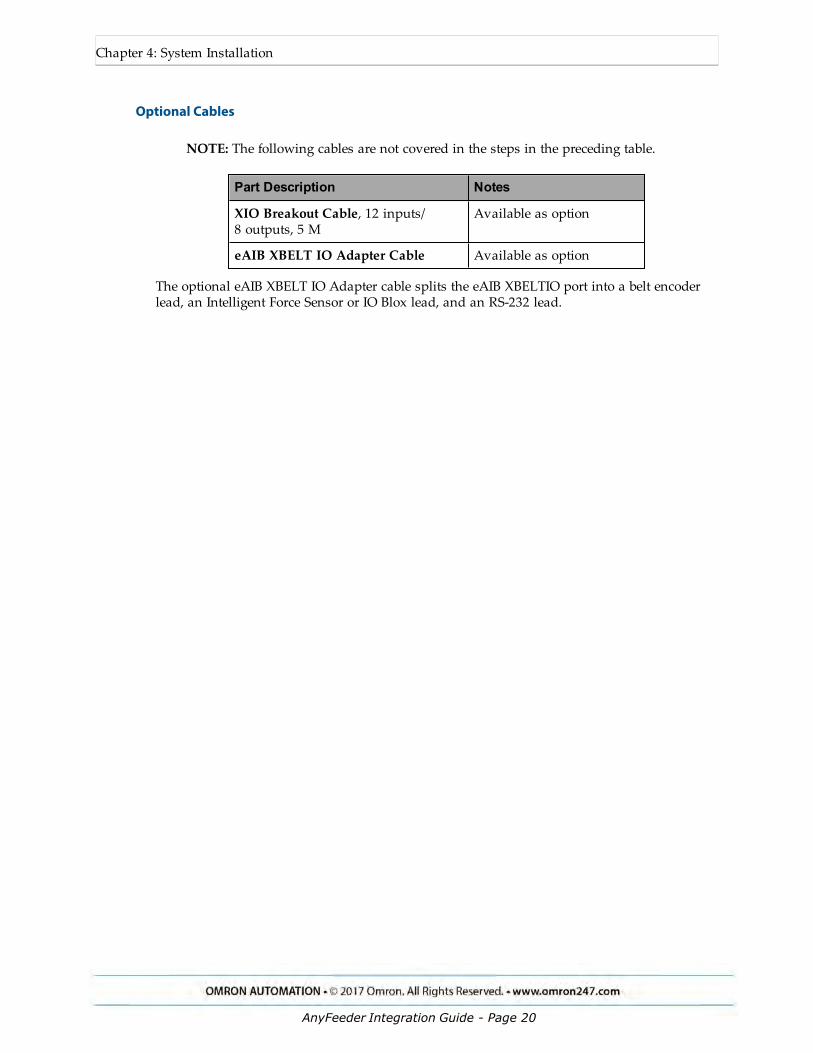
Optional Cables
NOTE: The following cables are not covered in the steps in the preceding table.
Part Description Notes
XIO Breakout Cable, 12 inputs/8 outputs, 5 M
Available as option
eAIB XBELT IO Adapter Cable Available as option
The optional eAIB XBELT IO Adapter cable splits the eAIB XBELTIO port into a belt encoderlead, an Intelligent Force Sensor or IO Blox lead, and an RS-232 lead.
AnyFeeder Integration Guide - Page 20

Chapter 4: System Installation
4.2 System Cables, with SmartController
When the optional SmartController EX is included in the system, the Pendant, Front Panel,and XUSR connections must connect to the SmartController EX.
DC
IN
24 VGND
AC
200 -240 V
Ø1 XB
ELT
IO
XIO Servo
ENETENETXSYSTEM
8 mm ODAir line
Belt orTarget
24 VDC, 6 APower Supply
200-240 VAC10 Asingle-phase AC Power
Cable
DC Power Cable
Front Panel Cable
Front Panel
T20 Adapter Cable
XMCP Jumper Plug
XMCP
XFP
XUSR
XUSR Jumper Plug
eAIB or eMB-40/60RInterface Panel
XUSR for: - User E-Stop/Safety Gate- Muted Safety Gate
The Jumper Plug is required if neither of these is used
T20 Bypass Plug
T20 Pendant (option) Either T20 Pendant,T20 Bypass Plug, or XMCP Jumper Plug must be used
Ethernet toSmartController
FP Jumper PlugEither Front Panel orFP plug must be used
Ethernet to SmartVision MX
User-suppliedSwitch (option)
24 VDC10 APowerSupply
RS232
DC Servo Cable
eAIB Interface Panel
RS232
DCPowerCable
IEEE 1394
24 VDC, 6 APower Supply
SmartVision MXDC Power
Cable
Camera
Connectionson back side
AnyFeederSX240 shown
Robot, eCobra600 shown
SmartController EX
L
M
QR S
V U
T
M
GH
J
B
ED
F
C
K
P
M
A W
W
X
7a 10
8
1
6
7
9
8
11
3
4a
4
3a
4a
4
2
3
2a
12 3 4
13
12
12
9
N2N1
Figure 4-2. System Cable Diagram with SmartController
Installing a SmartController Motion Controller
Refer to the SmartController EX User’s Guide for complete information on installing the optionalSmartController. This list summarizes the main steps.
AnyFeeder Integration Guide - Page 21

Chapter 4: System Installation
1. Mount the SmartController and Front Panel.
2. Connect the Front Panel to the SmartController.
3. Connect the pendant (if purchased) to the SmartController.
Connect a jumper plug, if no pendant is being used.
4. Connect user-supplied 24 VDC power to the controller.
Refer to the SmartController EX User’s Guide.
5. Install a user-supplied ground wire between the SmartController and ground.
List of Cables and Parts
Part Cable and Parts List Part # Part of: Notes
A eAIB XSYS Cable 13323-000 standard, eAIB
B User E-Stop, Safety Gate n/a n/a user-supplied
C XUSR Jumper Plug 04736-000 13323-000 SmartController EX
D Front Panel 90356-10358 standard
E Front Panel Cable 10356-10500 90356-10358 standard
F Front Panel Jumper Plug 10053-000 13323-000 SmartController EX
G XMCP Jumper Plug 04737-000 13323-000 SmartController EX
H T20 Bypass Plug 10048-000 10055-000 standard, T20
J T20 Adapter Cable 10051-003 10055-000 standard, T20
K T20 Pendant (option) 10055-000 option
L AC Power Cable 04118-000 90565-010 user-supplied/option
M 24 VDC Power Cable 04120-000 90565-010 user-supplied/option
N1 24 VDC, 6 A Power Sup-ply
04536-000a or user-supplied
N2 24 VDC, 6 A Power Sup-ply
04536-000 90565-010 04536-000
P RS232 Cable toAnyFeeder
n/a AnyFeeder AnyFeeder
Q Ethernet Cable, toSmartController
n/a n/a user-supplied
R Ethernet Cable, toSmartVision MX
n/a n/a user-supplied
S Ethernet Switch(optional)
n/a n/a user-supplied
T Camera and cable n/a n/a user-supplied
AnyFeeder Integration Guide - Page 22

Chapter 4: System Installation
Part Cable and Parts List Part # Part of: Notes
U DC Servo Cable toAnyFeeder
n/a AnyFeeder AnyFeeder
V 24 VDC, 10 A powersupply
n/a n/a user-supplied
W IEEE 1394 cable n/a n/a standard
X 8 mm OD Air Line n/a n/a user-supplied
a: Only one 04536-000 power supply comes with the 90565-010 kit.
The XUSR, XMCP, and XFP jumpers intentionally bypass safety connections so you can testthe system functionality during setup.
WARNING: Under no circumstances should you run arobot system, in production mode, with all three jumpersinstalled. This would leave the system with no E-Stops.
Cable Installation Overview
Step Connection Part
1 Connect eAIB XSYS cable to XSYSTEM on eAIB or eMB-40/60R A
2 Connect a user E-Stop or Muted Safety Gate to the XUSR connector or B
2a verify XUSR jumper plug is installed in XUSR connector. C
3 Connect Front Panel cable to Front Panel and XFP connector or D, E
3a if no Front Panel, install FP jumper on XFP connector. F
4 Connect Pendant adapter cable to XMCP connector or J, K
4a if no Pendant, install XMCP jumper or bypass plug. G orH
5 Connect user-supplied ground to robot. See robot user's guide for location. n/a
5a Connect user-supplied ground to SmartController EX. See SmartControllerEX user's guide for location.
n/a
5b Connect user-supplied ground to SmartVision MX. See SmartVision MXuser's guide for location.
n/a
6 Connect 200-240 VAC to AC Input on eAIB; secure with clamp. L
7 Connect 24 VDC to DC Input on eAIB and SmartController EX. N2,M
7a Connect 24 VDC to SmartVision MX. N1,M
8 Connect RS232 cable from SmartVision MX to Anyfeeder. P
9 Connect Ethernet cable between SmartController EX and SmartVision MX. Aswitch can be used between the two.
Q, R
AnyFeeder Integration Guide - Page 23

Chapter 4: System Installation
Step Connection Part
10 Connect camera and cable to SmartVision MX. Use USB PoE 1 on MX. T
11 Connect 24 VDC Servo cable to DC Input on AnyFeeder interface panel. U, V
12 Connect an 8 mm OD air line to the pneumatic connector SX240, SX340. X
13 Connnect IEEE 1394 cable between SmartController EX and eAIB SmartServo. W
Optional Cables
NOTE: The following cables are not covered in the steps in the preceding table.
Part Description Notes
XIO Breakout Cable, 12 inputs/8 outputs, 5 M
Available as option
Y Cable, for XSYS cable connectionsto dual robots
Available as option withSmartController EX
eAIB XBELT IO Adapter Cable Available as option
The XIO Breakout cable is for using the I/O on the eAIB.
The Y cable attaches at the SmartController EX XSYS connector, and splits it into two XSYSconnectors. This is part number 00411-000. See the Dual Robot Configuration Guide.
The optional eAIB XBELT IO Adapter cable splits the eAIB XBELTIO port into a belt encoderlead, an Intelligent Force Sensor or IO Blox lead, and an RS-232 lead. If the system has aSmartController EX, this is only needed for Intelligent Force Sensing.
4.3 AnyFeeder Connections
Electrical Connectors on Interface Panel
Servo Motor Cableto 24 VDC supply
Serial connectionto SmartVision MX
Figure 4-3. Electrical Connectors on AnyFeeder Interface Panel
AnyFeeder Integration Guide - Page 24

Chapter 4: System Installation
NOTE: The Aux I/O connector is not used in an Omron Adept system.
Table 4-1. Electrical Connector Pinout
Description Function Type Pin#
Pinout Cable
J1 High Power onservomotor
D-sub-M2 + 5
A1 24 VDC No. 1 (red)
A2 GROUND No. 2 (blue)
J2 RS232 D-sub 9,female
2 RX D-sub 9, female
3 TX
5 GROUND
J4 Aux I/O D-sub 15 1 Trigger out Not used
4 GROUND
5 GROUND
6 24 VDC out
7 24 VDC out
8 Pick in
9 Flash in
14 Error Drive 1
15 Error Drive 2
Installing Cables and Power
The AnyFeeder requires the following cable connections:
l the servo motor cable (supplied)
l the RS-232 serial communications cable (supplied)
The AnyFeeder is equipped with fuses to protect the internal components.The motor power 24 VDC input is protected with a 10 Amp fuse, and the parallel I/O 24 VDClines are protected with a 3 Amp fuse. These fuses can be replaced in the field.If you suspect a problem with one or both of these fuses, contact your local Omron Support.
AnyFeeder Integration Guide - Page 25
Chapter 4: System Installation
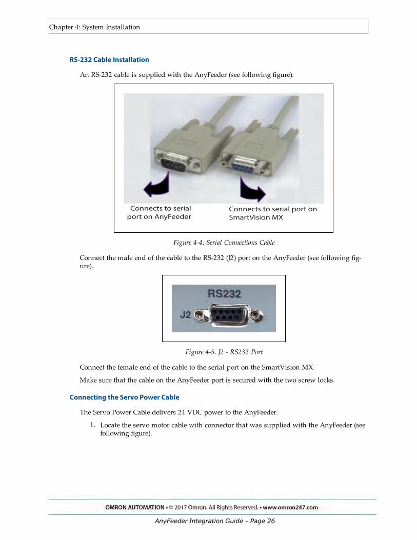
RS-232 Cable Installation
An RS-232 cable is supplied with the AnyFeeder (see following figure).
Connects to serialport on AnyFeeder
Connects to serial port on SmartVision MX
Figure 4-4. Serial Connections Cable
Connect the male end of the cable to the RS-232 (J2) port on the AnyFeeder (see following fig-ure).
Figure 4-5. J2 - RS232 Port
Connect the female end of the cable to the serial port on the SmartVision MX.
Make sure that the cable on the AnyFeeder port is secured with the two screw locks.
Connecting the Servo Power Cable
The Servo Power Cable delivers 24 VDC power to the AnyFeeder.
1. Locate the servo motor cable with connector that was supplied with the AnyFeeder (seefollowing figure).
AnyFeeder Integration Guide - Page 26

Chapter 4: System Installation
Figure 4-6. Servo Power Cable
2. Connect the wire end of the cable to the user-supplied 24 VDC / 10 A regulated powersupply.
3. Attach the connector end of the cable to the Motor Power 24 VDC In (J1) connector onthe front of the AnyFeeder (see following figure).
Figure 4-7. J1 - 24 VDC In Connector
NOTE: The five smaller pins in the center of this connector are not used bythe AnyFeeder.
AnyFeeder Integration Guide - Page 27

Chapter 4: System Installation
Installing the Pneumatic Line
This section describes the pneumatic installation procedure for the AnyFeeder SX240 andSX340. The AnyFeeder SXM100 and SXM140 do not take a pneumatic line.
1. Locate the pneumatic connector below the side handle on the AnyFeeder.
Figure 4-8. Pneumatic Connector Location on AnyFeeder SX240
2. Prepare an 8 mm OD air line.
3. Attach the air line to the pneumatic connector (see following figure). Do not overtightenthe connection.
Figure 4-9. Air Line Attached to Pneumatic Connector
AnyFeeder Integration Guide - Page 28

Chapter 5: Configuration with ACE Software
NOTE: Instructions for using serial communication with an AnyFeeder are coveredin the User’s Guide.
5.1 ACE Software
The following software is pre-loaded on the SmartVision MX hard drive:
l Windows® 7 Embedded
l ACE
ACE 3.7.3.150 or later is required to support all of the AnyFeeders listed in this guide
l ACE Sight 3 (ACE-based vision software)
l Drivers for Basler ACE cameras
The SmartVision MX is designed to run ACE software. We do not support applications otherthan ACE.
The SmartVision MX does not come with:
l Keyboard
l Mouse
l Monitor
These are user-supplied, so you can run the ACE and ACE Sight applications, and well as con-trol shutting down the SmartVision MX industrial PC.
The AnyFeeder can be controlled by V+ programs, usually generated by the setup wizards inACE. This chapter provides an overview of that process.
We recommend that you use the graphical interface provided in the ACE software.For details, see the ACE User’s Guide, which is available within ACE under the Help tab.
5.2 ACE Sight Overview
The ACE Sight module uses the SmartVision MX to handle all vision operations. ACE Sightrequires the ACE Sight USB license key [dongle], installed in the SmartVision MX, for full func-tionality.
Initial Configuration
A number of steps need to be taken to use ACE with an AnyFeeder.
l Create one Locator Model for each type of part that will be handled.
l Teach a “safe” location (where the robot goes on power-up)
AnyFeeder Integration Guide - Page 29

Chapter 5: Configuration with ACE Software
l Teach a picture-taking position, which is where the robot will move so that it doesn’tblock the camera’s view of the pick surface.
l Teach the camera field-of-view to the robot.
l Teach the robot where to place a part that it has picked.
Figure 5-1. Screen AnyFeeder Object
5.3 Pick and Place Sequence Wizard
ACE Sight has a wizard named SmartController Pick and Place Sample, which can be used tostep you through most of the steps needed to set up ACE Sight for use with an AnyFeeder.From the ACE Getting Started screen, select:
New Sample Application > ACE Sight/V+ Application > SmartController Pick and Place
NOTE: When you first start ACE, you will have access to this wizard. Refer to thefollowing figure.
We will not repeat all of the screens shown in this wizard. In general, you just need to followthe on-screen instructions.
You start by Selecting the Configuration. In our example configuration, with no upward-look-ing camera and no conveyor belt, the wizard has four phases. Other configurations will vary.
l Phase 1/4 - Select Robot
Select SmartController
Select Robot
Configure End-effector (requires power-on)
Teach Safe Position
l Phase 2/4 – Create Feeder - Feeder model, backlight, motion sequences
l Phase 3/4 – Teach Pick for Arm- or Fixed-Camera Configuration
AnyFeeder Integration Guide - Page 30

Chapter 5: Configuration with ACE Software
This includes camera setup, calibration, and Locator Model creation.
l Phase 4/4 - Teach Place for Static Position Configuration
Figure 5-2. ACE Sight Pick and Place Sample
Safe and Picture-taking Positions
For teaching the Safe Position or Picture Position, you can either move the robot using apendant, the jog pendant feature in ACE, or move the robot manually. Some of the joints mayneed to be released with the brake release button when moving them manually.
The Safe Position is where the robot moves when its current motion gets interrupted orstopped.
The location of these positions can affect the system’s efficiency.
After selecting the Safe and Picture-taking Positions, verify that the robot can reach those pos-itions, with all joints remaining within their limits, by clicking Move in the bottom left of thescreen.
NOTE: If possible, make the tool flange higher than the sides of the AnyFeeder inboth of these positions, to reduce any chance of a collision.
Create Feeder
This step includes specifying the AnyFeeder model you are using, its position, checking thefunctionality of its backlight (if present), as well as a variety of motion sequences.
AnyFeeder Integration Guide - Page 31
Chapter 5: Configuration with ACE Software
NOTE: ACE 3.7.3.150 or later is required for support of all four AnyFeeder models.
You can position the AnyFeeder within the ACE 3-D visualizaion, so that it matches how yourAnyFeeder is actually installed.
You also have the opportunity to test the backlight, if your AnyFeeder has one.
Teach Pick for Arm- or Fixed-Mount Camera
This step includes creating a camera object, setting the camera properties, performing a gridcalibration, teaching a Locator Model and picture position. It will then step you through loc-ating an instance of the object, teaching the pick position, and performing an automatic cal-ibration. It ends with a calibration summary and teaching a vision histogram tool.
l Make sure your part is well lit. It is better to have more light and a lower exposure.
l In the Virtual Camera, under Acquisition Settings, edit the current settings. Under VideoFormat, ensure that the exposure is set to a low value to reduce blur.
l Adjust the lens aperture and focus of your camera until you obtain a good image.
l When focusing the lens, using a sheet of printed text at the height of the part is often thebest way to get the focus correct.
l You may also need to edit the Acquisition Settings to get the best image.
Using the Calibration Grid
A pdf of the dot grid, used for camera calibration, is located in your Omron folder under Pro-gram Files. Use the file DotPitch10_CalibrationTarget.pdf in the ACE folder.
l Calibration establishes the mm/pixel ratio of the field of view of the camera and com-pensates for lens distortion.
l Make sure your calibration grid is printed to scale. The actual pitch between the dotsmust match the nominal pitch in both directions. Specifically, in the printer settings,you must make sure the grid is printed at actual size and not to fit or shrunk. For theAnyFeeder SXM100 and SXM140 you will have to trim some of the paper off after print-ing for it to fit inside the feed surface. This will not affect calibration.
l When you place it under the camera, it should fill the entire field of view. It must alsobe flat over its entire surface.
l Ensure that the height of the dot-grid matches the height of the parts being picked in thefield of view. The closer the lens is to the part and the tighter the tolerances, the morecritical this becomes.
l Do not change the lens settings, either the focus or aperture, after calibration.
l Calibration can be performed in the virtual camera object or during the addition of acamera to a workspace.
AnyFeeder Integration Guide - Page 32

Chapter 5: Configuration with ACE Software
Figure 5-3. Grid Calibration Screen Shot
AnyFeeder Integration Guide - Page 33

Chapter 5: Configuration with ACE Software
Locator Model
In creating your Locator Model(s), ensure that you leave room for the part and tool flange/-gripper to clear the walls of the AnyFeeder. The gripper shape, placement of the pick point onthe part, and the region of interest can all affect this.
Figure 5-4. Sample Locator Model Screen Shot
AnyFeeder Integration Guide - Page 34

Chapter 5: Configuration with ACE Software
Create Region of Interest
The Locator Model creation is followed by creating a region of interest, where the software willlook for instances of the Model.
The green box shown in the following picture can be adjusted. This step is critical, since therobot should be able to pick any part inside this region.
Test the robot to verify that it can reach each edge of the green box region (Region of Interest)without touching the bulk container, feeder platform side panels, or feeder platform frontpanel.
Figure 5-5. Region of Interest
Teach Picture-taking Position
Choose a position such that the robot does not interfere with the camera’s view.
If, in Select Configuration, you selected using an upward-facing camera to refine the position ofa picked part, the wizard would step you through that at this time. Typically, you don’t needto set up another camera to refine the position, but for applications requiring more precision inplacement, you can add another camera to refine the position of the part in the gripper.
Automatic Calibration
The next step is to run the automatic calibration. The purpose of this is to make sure the robotcan pick any parts that are within the vision window based on the camera picture received.During this process, the robot works with the vision system to first see where the part is (whilethe robot is waiting at picture-taking position) and then the SmartVision MX calculates the loc-ation and directs the robot to pick up the part. If the camera calibration is performed correctly,
AnyFeeder Integration Guide - Page 35

Chapter 5: Configuration with ACE Software
typically the position error will be less than 1 mm. The valid scale factor range is from 0.92 to1.08 mm.
Figure 5-6. Summary of Automatic Calibration
Teach Vision Histogram Tool
The next step is to set up the histogram tool for the application. You can divide the vision win-dow into three boxes corresponding to three zones: Dispense Zone, Flip Zone, and Front Zone.These areas can be adjusted by dragging the edge of the boxes. Refer to figure Front, Flip, andDispense Zones on page 43
l The Dispense zone is used to find out if there are too many parts, and if a feed forwardis needed.
l The Flip zone is the area where the robot is supposed to pick up the parts.
This is typically set up to cover the center of the pick window, as well as half of the dis-pense zone and half of the front zone.
l The Front zone is the front area of the pick window.
Teach Place Position
After the Histogram tool is taught, you will be stepped through teaching the Place location.After this, the Pick and Place Wizard is completed.
AnyFeeder Integration Guide - Page 36
Chapter 6: Fine-Tuning
6.1 Configuration Refinement
At this point, the system will be able to recognize the Locator Model taught during the wizardand perform automated pick and place. Most applications can be improved by adjusting para-meters that aren’t covered in the sample application wizard. This could include advancedproperties of the vision tools, differentiating between multiple part types, sorting to multipleplace locations, avoiding picking overlapping parts, or detecting part defects.
6.2 Multiple Locator Models
In our dental floss application, we will add another Locator Model, since the dental floss partsdispensed inside the AnyFeeder could be lying with either side up.
To add another Locator Model, in the workspace Explorer window on the left, simply right-click on the Pick folder > New > Vision > Tool > Locator Model, then go through the same pro-cess in creating another Model.
To add another Locator Model, in the Workspace Explorer window on the left, right-click onPick within the ACE Sight Pick and Place folder, then select:
New > Vision > Tool > Locator Model.
Repeat the process performed in the wizard for creating a Model.
Double-click to open the Locator, and drag in the new Locator Model: Floss_Side2 created.Click Run so the camera can find both Models.
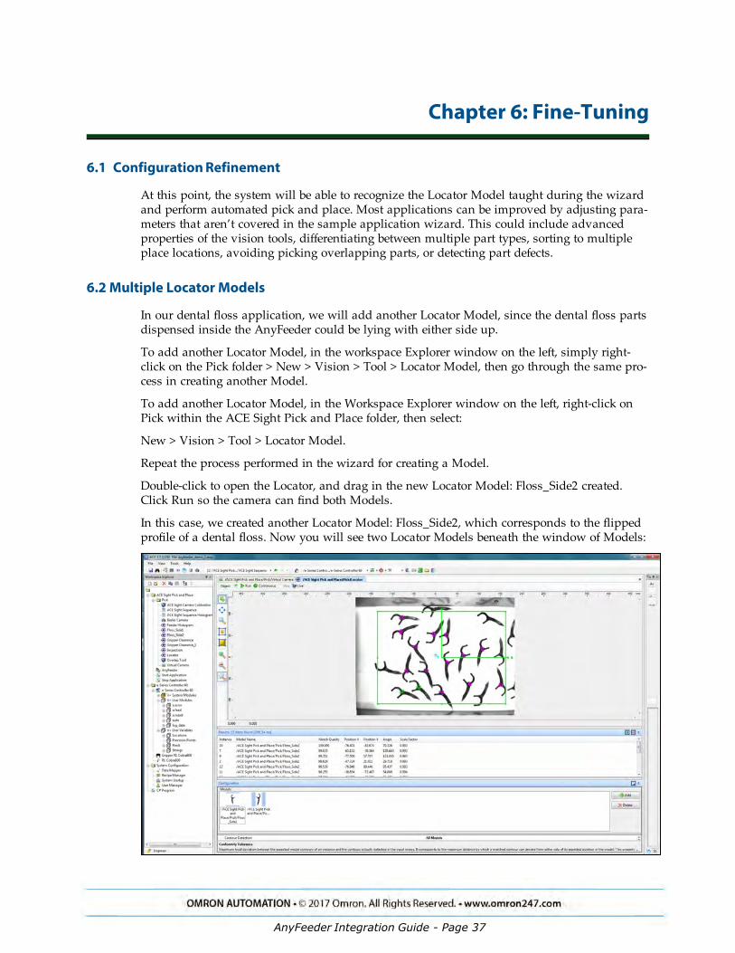
In this case, we created another Locator Model: Floss_Side2, which corresponds to the flippedprofile of a dental floss. Now you will see two Locator Models beneath the window of Models:
AnyFeeder Integration Guide - Page 37
Chapter 6: Fine-Tuning
Figure 6-1. Dual Locator Models
In the Workspace Explorer – e-Series Controller 60 – V+ User Modules – a.feed folder, you canpull up the V+ program related to AnyFeeder motion sequence.
The fd.main() under the a.feed folder is the program that tied the ACE Sight histogram Tool tothe AnyFeeder motion sequence. The default setting is as below that when the instance countis 0, the AnyFeeder motion sequence will be triggered based on four cases related to front.dent(Front zone density), flip.den ( Flip zone density) and dispense.den ( Dispense zone density).
The fd.main() program is shown below:
PROGRAM fd.main()
;
; ABSTRACT: Background task controlling the Feeder
;
; INPUTS: None
;
; OUTPUTS: None
;
GLOBAL REAL pick.seq
GLOBAL $sv.client_ip
AUTO REAL front.den, flip.den, dispense.den, inst.count
REACTE fd.reacte
WHILE rob.run DO
; Execute the sequence to locate parts for picking
VRUN $sv.client_ip, pick.seq
VWAITI (pick.seq) $sv.client_ip, 0
inst.count = VRESULT($sv.client_ip, pick.seq, 3, 1, 1310, 1, 1)
; If instances are found, let the robot know it can pick
; the parts and wait for it to complete
IF (inst.count > 0) THEN
fd.ready = TRUE
WHILE fd.ready
WAIT
END
inst.count = inst.count-1
END
IF (inst.count == 0) THEN
; Calculate product densities in the 3 zones
CALL fd.density(front.den, flip.den, dispense.den)
CASE TRUE OF
VALUE front.den > fd.front.thres:
; Move the product backward from the front zone
AnyFeeder Integration Guide - Page 38

Chapter 6: Fine-Tuning
CALL fd.execute(fd.ms.frontmove)
VALUE flip.den > fd.flip.thres:
; Flip the product in the pick zone
CALL fd.execute(fd.ms.pickflip)
VALUE dispense.den < fd.disp.thres:
; Dispense more product into the feeder
CALL fd.execute(fd.ms.dispense)
VALUE flip.den < fd.flip.thres:
; Move the product from dispense zone to the pick zone
CALL fd.execute(fd.ms.pickmove)
END
END
END
RETURN
.END
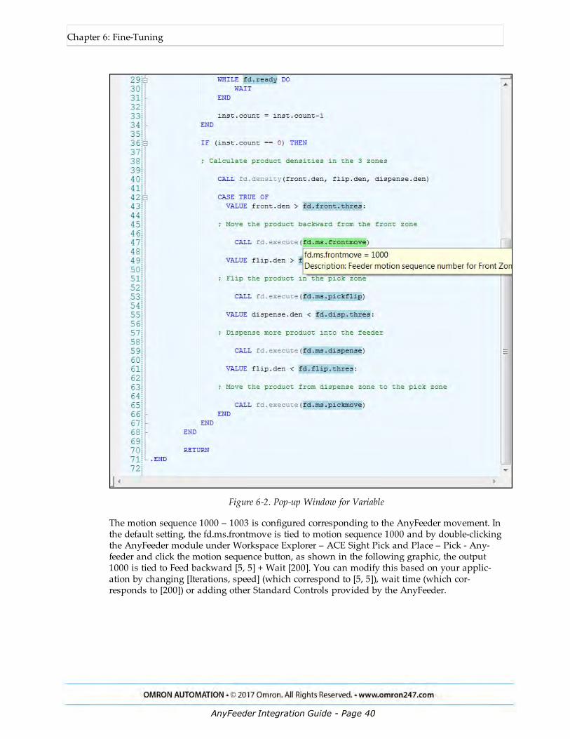
When moving the cursor to the fd.ms.frontmove, a yellow window pops up: the description ofthis variable is tied to motion sequence 1000 as shown below:
AnyFeeder Integration Guide - Page 39
Chapter 6: Fine-Tuning
Figure 6-2. Pop-up Window for Variable
The motion sequence 1000 – 1003 is configured corresponding to the AnyFeeder movement. Inthe default setting, the fd.ms.frontmove is tied to motion sequence 1000 and by double-clickingthe AnyFeeder module under Workspace Explorer – ACE Sight Pick and Place – Pick - Any-feeder and click the motion sequence button, as shown in the following graphic, the output1000 is tied to Feed backward [5, 5] + Wait [200]. You can modify this based on your applic-ation by changing [Iterations, speed] (which correspond to [5, 5]), wait time (which cor-responds to [200]) or adding other Standard Controls provided by the AnyFeeder.
AnyFeeder Integration Guide - Page 40

Chapter 6: Fine-Tuning
Figure 6-3. AnyFeeder Motion Sequence Parameters
You can get access to all of the Standard Controls that are provided by the AnyFeeder Objectwindow by clicking the Standard Controls button and by adjusting the values for Iterationsand Speed. You can test how these motion sequences work with your parts inside theAnyFeeder.
AnyFeeder Integration Guide - Page 41

Chapter 6: Fine-Tuning
Figure 6-4. Standard Controls
As an example, we will use the dental floss motion sequence 1002. Initially, the motionsequence 1002 is tied to Dispense [5, 5] and Wait [200], but if the AnyFeeder vision windowshows most of the parts overlapping each other, or most of the parts presented only in the dis-pense zone, you can try adding flip forward or flip. You will need to experiment with differentiterations and speeds to see how the parts disperse inside the vision window.
Since the type of part and how the parts piled inside the upper bin will also affect how youdefine feedforward and dispense sequence, the settings for those motion sequence will largelydepend on your application.
From the window below, the vision window is divided into three zones and you can find thedensity percentage in three zones shown in the Results window below the vision window.
The front.den corresponds to the Front Zone %, the flip.den corresponds to the Flip Zone %and the dispense.den corresponds to the Dispense Zone %.
AnyFeeder Integration Guide - Page 42
Chapter 6: Fine-Tuning
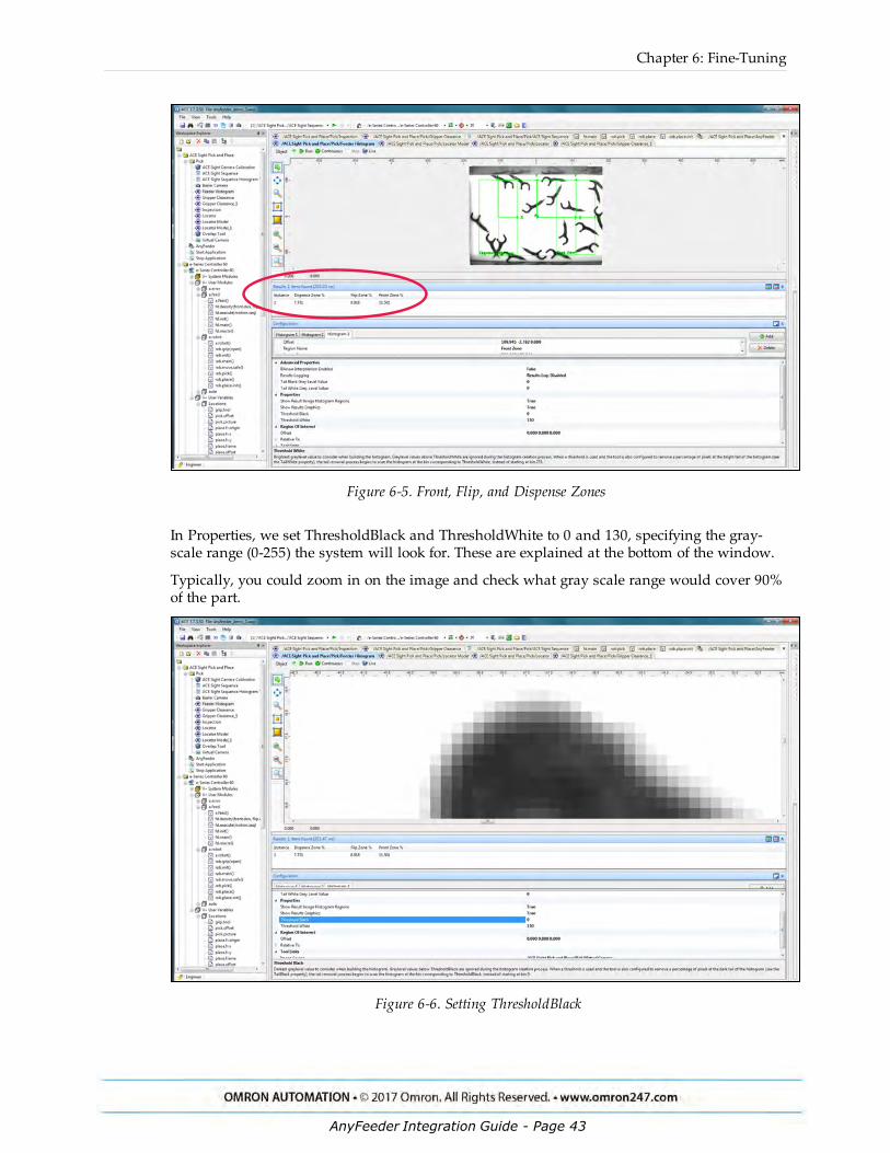
Figure 6-5. Front, Flip, and Dispense Zones
In Properties, we set ThresholdBlack and ThresholdWhite to 0 and 130, specifying the gray-scale range (0-255) the system will look for. These are explained at the bottom of the window.
Typically, you could zoom in on the image and check what gray scale range would cover 90%of the part.
Figure 6-6. Setting ThresholdBlack
AnyFeeder Integration Guide - Page 43
Chapter 6: Fine-Tuning
With a dark background, you will want to adjust the setting for ThresholdBlack and Threshold-White.
By triggering the motion sequence 1000 – 1003, you can test how the parts will dispense insidethe three zones when different motion sequences are triggered.
From the fd.main() program, in the four cases related to triggering motion sequence 1000 –1003, you can adjust the fd.front.thres, fd.flip.thres, and fd.disp.thres to achieve the most effi-cient settings.
CASE TRUE OF
VALUE front.den > fd.front.thres:
; Move the product backward from the front zone
CALL fd.execute(fd.ms.frontmove)
VALUE flip.den > fd.flip.thres:
; Flip the product in the pick zone
CALL fd.execute(fd.ms.pickflip)
VALUE dispense.den < fd.disp.thres:
; Dispense more product into the feeder
CALL fd.execute(fd.ms.dispense)
VALUE flip.den < fd.flip.thres:
; Move the product from dispense zone to the pick zone
CALL fd.execute(fd.ms.pickmove)
END
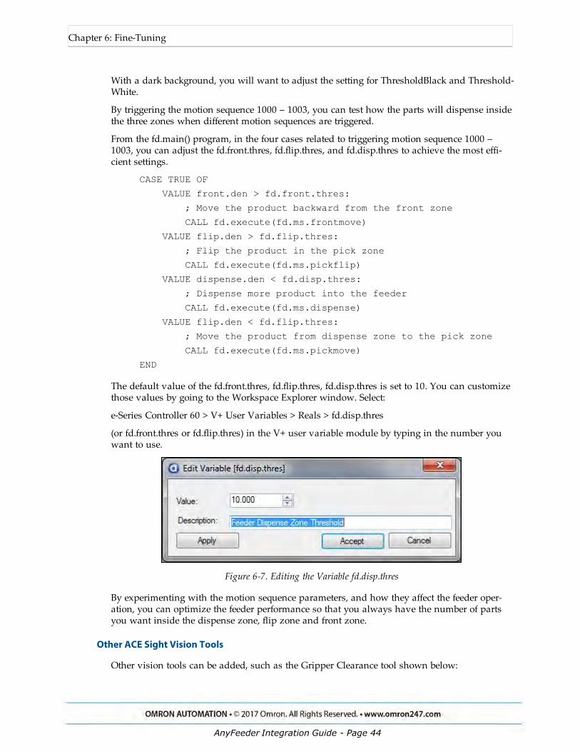
The default value of the fd.front.thres, fd.flip.thres, fd.disp.thres is set to 10. You can customizethose values by going to the Workspace Explorer window. Select:
e-Series Controller 60 > V+ User Variables > Reals > fd.disp.thres
(or fd.front.thres or fd.flip.thres) in the V+ user variable module by typing in the number youwant to use.
Figure 6-7. Editing the Variable fd.disp.thres
By experimenting with the motion sequence parameters, and how they affect the feeder oper-ation, you can optimize the feeder performance so that you always have the number of partsyou want inside the dispense zone, flip zone and front zone.
Other ACE Sight Vision Tools
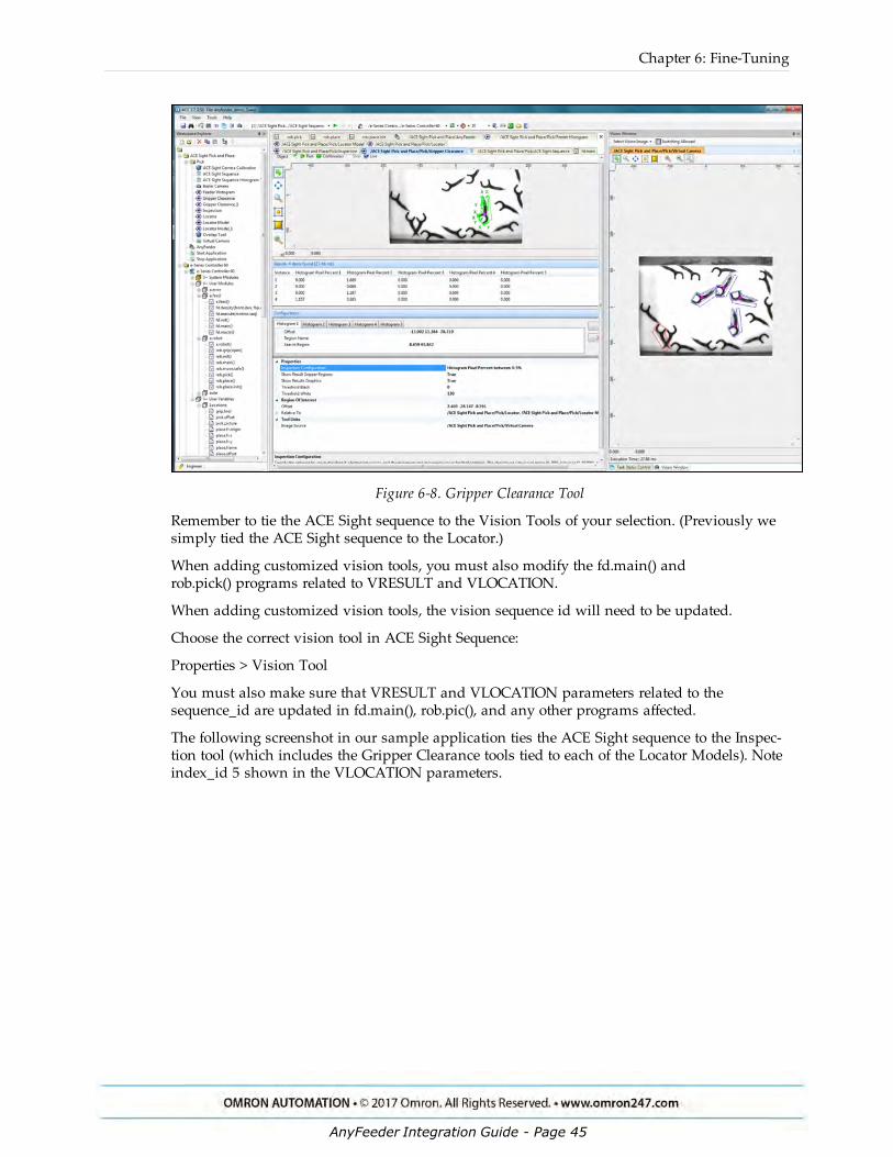
Other vision tools can be added, such as the Gripper Clearance tool shown below:
AnyFeeder Integration Guide - Page 44
Chapter 6: Fine-Tuning
Figure 6-8. Gripper Clearance Tool
Remember to tie the ACE Sight sequence to the Vision Tools of your selection. (Previously wesimply tied the ACE Sight sequence to the Locator.)
When adding customized vision tools, you must also modify the fd.main() androb.pick() programs related to VRESULT and VLOCATION.
When adding customized vision tools, the vision sequence id will need to be updated.
Choose the correct vision tool in ACE Sight Sequence:
Properties > Vision Tool
You must also make sure that VRESULT and VLOCATION parameters related to thesequence_id are updated in fd.main(), rob.pic(), and any other programs affected.
The following screenshot in our sample application ties the ACE Sight sequence to the Inspec-tion tool (which includes the Gripper Clearance tools tied to each of the Locator Models). Noteindex_id 5 shown in the VLOCATION parameters.
AnyFeeder Integration Guide - Page 45

Chapter 6: Fine-Tuning
Figure 6-9. ACE Sight Index ID Used in Sample Code
The parameters shown below are V+ vision keywords that will be useful if you want to cus-tomize the system:
l VRUN: Initiates execution of a vision sequence
l VLOCATION: Returns the Cartesian transform result of sequence
l VPARAMETER: Sets the current value of a vision parameter
l VRESULT: Returns specified result of a vision sequence
l VSTATE: Returns the state of execution of a vision sequence
l VWAITI: Waits for a vision sequence to reach a specific state
For a detailed explanation and examples of these keywords, go to:
Help > ACE Guides > ACE Reference Guide > ACE Sight V+ and MicroV+ Keywords.
AnyFeeder Integration Guide - Page 46

Manual written by Omron Adept Technologies, IncPublication reference: 18831-000, Rev A
For support please contact your local Omron Support
Center: www.ia.omron.com
R262I-E-
Revision code
Date of revision Revision reason and revision page
01 August. 23, 2017 First edition
7 Revision History
AnyFeeder Integration Guide - Page 47
OMRON CANADA, INC. • HEAD OFFICEToronto, ON, Canada • 416.286.6465 • 866.986.6766 • www.omron247.com
OMRON ELECTRONICS DE MEXICO • HEAD OFFICEMéxico DF • 52.55.59.01.43.00 • 01-800-226-6766 • [email protected]
OMRON ELECTRONICS DE MEXICO • SALES OFFICEApodaca, N.L. • 52.81.11.56.99.20 • 01-800-226-6766 • [email protected]
OMRON ELETRÔNICA DO BRASIL LTDA • HEAD OFFICESão Paulo, SP, Brasil • 55.11.2101.6300 • www.omron.com.br
OMRON ARGENTINA • SALES OFFICECono Sur • 54.11.4783.5300
OMRON CHILE • SALES OFFICESantiago • 56.9.9917.3920
OTHER OMRON LATIN AMERICA SALES54.11.4783.5300
Authorized Distributor:
R262I-E-01 08/17 Note: Specifications are subject to change. © 2017 Omron. All Rights Reserved. Printed in U.S.A.
Printed on recycled paper.
OMRON AUTOMATION AMERICAS HEADQUARTERS • Chicago, IL USA • 847.843.7900 • 800.556.6766 • www.omron247.com
OMRON EUROPE B.V. • Wegalaan 67-69, NL-2132 JD, Hoofddorp, The Netherlands. • +31 (0) 23 568 13 00 • www.industrial.omron.eu
Controllers & I/O • Machine Automation Controllers (MAC) • Motion Controllers • Programmable Logic Controllers (PLC) • Temperature Controllers • Remote I/O
Robotics • Industrial Robots • Mobile Robots
Operator Interfaces• Human Machine Interface (HMI)
Motion & Drives• Machine Automation Controllers (MAC) • Motion Controllers • Servo Systems • Frequency Inverters
Vision, Measurement & Identification• Vision Sensors & Systems • Measurement Sensors • Auto Identification Systems
Sensing• Photoelectric Sensors • Fiber-Optic Sensors • Proximity Sensors • Rotary Encoders • Ultrasonic Sensors
Safety • Safety Light Curtains • Safety Laser Scanners • Programmable Safety Systems • Safety Mats and Edges • Safety Door Switches • Emergency Stop Devices • Safety Switches & Operator Controls • Safety Monitoring/Force-guided Relays
Control Components • Power Supplies • Timers • Counters • Programmable Relays • Digital Panel Meters • Monitoring Products
Switches & Relays • Limit Switches • Pushbutton Switches • Electromechanical Relays • Solid State Relays
Software • Programming & Configuration • Runtime


![Channel Partner Integration Guide...Channel Partner Integration Guide Channel Partner Integration Guide[Page 3] About Channel Partner Integration[Page 4] Integrating to a Website[Page](https://static.documents.pub/doc/80x56/604b23224068781c4925f2ad/channel-partner-integration-guide-channel-partner-integration-guide-channel.jpg)


