Refractory Installation Quality Control Guidelines—Inspection and Testing Monolithic Refractory Linings and Materials API RECOMMENDED PRACTICE 936 SECOND EDITION, FEBRUARY 2004 Copyright American Petroleum Institute Reproduced by IHS under license with API Licensee=Aramco HQ/9980755100 No reproduction or networking permitted without license from IHS --`,`,`,`,,,```,,,,`,,``````,``-`-`,,`,,`,`,,`---
Transcript
Refractory Installation Quality Control Guidelines—Inspectionand Testing Monolithic Refractory Linings and Materials
API RECOMMENDED PRACTICE 936SECOND EDITION, FEBRUARY 2004
Copyright American Petroleum Institute Reproduced by IHS under license with API Licensee=Aramco HQ/9980755100
Not for Resale, 12/03/2005 04:58:41 MSTNo reproduction or networking permitted without license from IHS
--`,`,`,`,,,```,,,,`,,``````,``-`-`,,`,,`,`,,`---
Copyright American Petroleum Institute Reproduced by IHS under license with API Licensee=Aramco HQ/9980755100
Not for Resale, 12/03/2005 04:58:41 MSTNo reproduction or networking permitted without license from IHS
--`,`,`,`,,,```,,,,`,,``````,``-`-`,,`,,`,`,,`---
Refractory Installation QualityControl Guidelines—Inspection and Testing Monolithic Refractory Linings and Materials
Downstream Segment
API RECOMMENDED PRACTICE 936SECOND EDITION, FEBRUARY 2004
Copyright American Petroleum Institute Reproduced by IHS under license with API Licensee=Aramco HQ/9980755100
Not for Resale, 12/03/2005 04:58:41 MSTNo reproduction or networking permitted without license from IHS
--`,`,`,`,,,```,,,,`,,``````,``-`-`,,`,,`,`,,`---
SPECIAL NOTES
API publications necessarily address problems of a general nature. With respect to partic-ular circumstances, local, state, and federal laws and regulations should be reviewed.
API is not undertaking to meet the duties of employers, manufacturers, or suppliers towarn and properly train and equip their employees, and others exposed, concerning healthand safety risks and precautions, nor undertaking their obligations under local, state, or fed-eral laws.
Information concerning safety and health risks and proper precautions with respect to par-ticular materials and conditions should be obtained from the employer, the manufacturer orsupplier of that material, or the material safety data sheet.
Nothing contained in any API publication is to be construed as granting any right, byimplication or otherwise, for the manufacture, sale, or use of any method, apparatus, or prod-uct covered by letters patent. Neither should anything contained in the publication be con-strued as insuring anyone against liability for infringement of letters patent.
Generally, API standards are reviewed and revised, reaffirmed, or withdrawn at least everyfive years. Sometimes a one-time extension of up to two years will be added to this reviewcycle. This publication will no longer be in effect five years after its publication date as anoperative API standard or, where an extension has been granted, upon republication. Statusof the publication can be ascertained from the API Standards department telephone (202)682-8000. A catalog of API publications, programs and services is published annually andupdated biannually by API, and available through Global Engineering Documents, 15 Inv-erness Way East, M/S C303B, Englewood, CO 80112-5776.
This document was produced under API standardization procedures that ensure appropri-ate notification and participation in the developmental process and is designated as an APIstandard. Questions concerning the interpretation of the content of this standard or com-ments and questions concerning the procedures under which this standard was developedshould be directed in writing to the Director of the Standards department, American Petro-leum Institute, 1220 L Street, N.W., Washington, D.C. 20005. Requests for permission toreproduce or translate all or any part of the material published herein should be addressed tothe Director, Business Services.
API standards are published to facilitate the broad availability of proven, sound engineer-ing and operating practices. These standards are not intended to obviate the need for apply-ing sound engineering judgment regarding when and where these standards should beutilized. The formulation and publication of API standards is not intended in any way toinhibit anyone from using any other practices.
Any manufacturer marking equipment or materials in conformance with the markingrequirements of an API standard is solely responsible for complying with all the applicablerequirements of that standard. API does not represent, warrant, or guarantee that such prod-ucts do in fact conform to the applicable API standard.
All rights reserved. No part of this work may be reproduced, stored in a retrieval system, or transmitted by any means, electronic, mechanical, photocopying, recording, or otherwise,
without prior written permission from the publisher. Contact the Publisher, API Publishing Services, 1220 L Street, N.W., Washington, D.C. 20005.
Copyright American Petroleum Institute Reproduced by IHS under license with API Licensee=Aramco HQ/9980755100
Not for Resale, 12/03/2005 04:58:41 MSTNo reproduction or networking permitted without license from IHS
--`,`,`,`,,,```,,,,`,,``````,``-`-`,,`,,`,`,,`---
FOREWORD
API publications may be used by anyone desiring to do so. Every effort has been made bythe Institute to assure the accuracy and reliability of the data contained in them; however, theInstitute makes no representation, warranty, or guarantee in connection with this publicationand hereby expressly disclaims any liability or responsibility for loss or damage resultingfrom its use or for the violation of any federal, state, or municipal regulation with which thispublication may conflict.
Suggested revisions are invited and should be submitted to API, Standards department,1220 L Street, NW, Washington, D.C. 20005, [email protected].
iii
Copyright American Petroleum Institute Reproduced by IHS under license with API Licensee=Aramco HQ/9980755100
Not for Resale, 12/03/2005 04:58:41 MSTNo reproduction or networking permitted without license from IHS
--`,`,`,`,,,```,,,,`,,``````,``-`-`,,`,,`,`,,`---
Copyright American Petroleum Institute Reproduced by IHS under license with API Licensee=Aramco HQ/9980755100
Not for Resale, 12/03/2005 04:58:41 MSTNo reproduction or networking permitted without license from IHS
Copyright American Petroleum Institute Reproduced by IHS under license with API Licensee=Aramco HQ/9980755100
Not for Resale, 12/03/2005 04:58:41 MSTNo reproduction or networking permitted without license from IHS
--`,`,`,`,,,```,,,,`,,``````,``-`-`,,`,,`,`,,`---
Copyright American Petroleum Institute Reproduced by IHS under license with API Licensee=Aramco HQ/9980755100
Not for Resale, 12/03/2005 04:58:41 MSTNo reproduction or networking permitted without license from IHS
--`,`,`,`,,,```,,,,`,,``````,``-`-`,,`,,`,`,,`---
1
Refractory Installation Quality Control Guidelines—Inspection and Testing Monolithic Refractory Linings and Materials
1 Introduction
1.1 SCOPE
This document provides installation quality control guide-lines for monolithic refractory linings and may be used tosupplement owner specifications. Materials, equipment, andpersonnel are qualified by the methods described, and appliedrefractory quality is closely monitored based on defined pro-cedures and acceptance criteria. The responsibilities ofinspection personnel who monitor and control the qualitycontrol process are also defined.
1.2 QUALITY CONTROL ELEMENTS
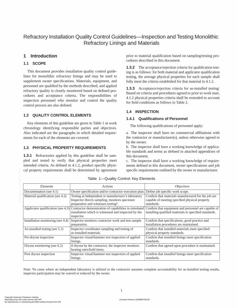
Key elements of this guideline are given in Table 1 in workchronology identifying responsible parties and objectives.Also indicated are the paragraphs in which detailed require-ments for each of the elements are covered.
1.3 PHYSICAL PROPERTY REQUIREMENTS
1.3.1
Refractories applied by this guideline shall be sam-pled and tested to verify that physical properties meetintended criteria. As defined in 4.1.2, product specific physi-cal property requirements shall be determined by agreement
prior to material qualification based on sampling/testing pro-cedures described in this document.
1.3.2
The acceptance/rejection criteria for qualification test-ing is as follows: for both material and applicator qualificationtesting, the average physical properties for each sample shallfully meet the criteria established for that material in 4.1.2.
1.3.3
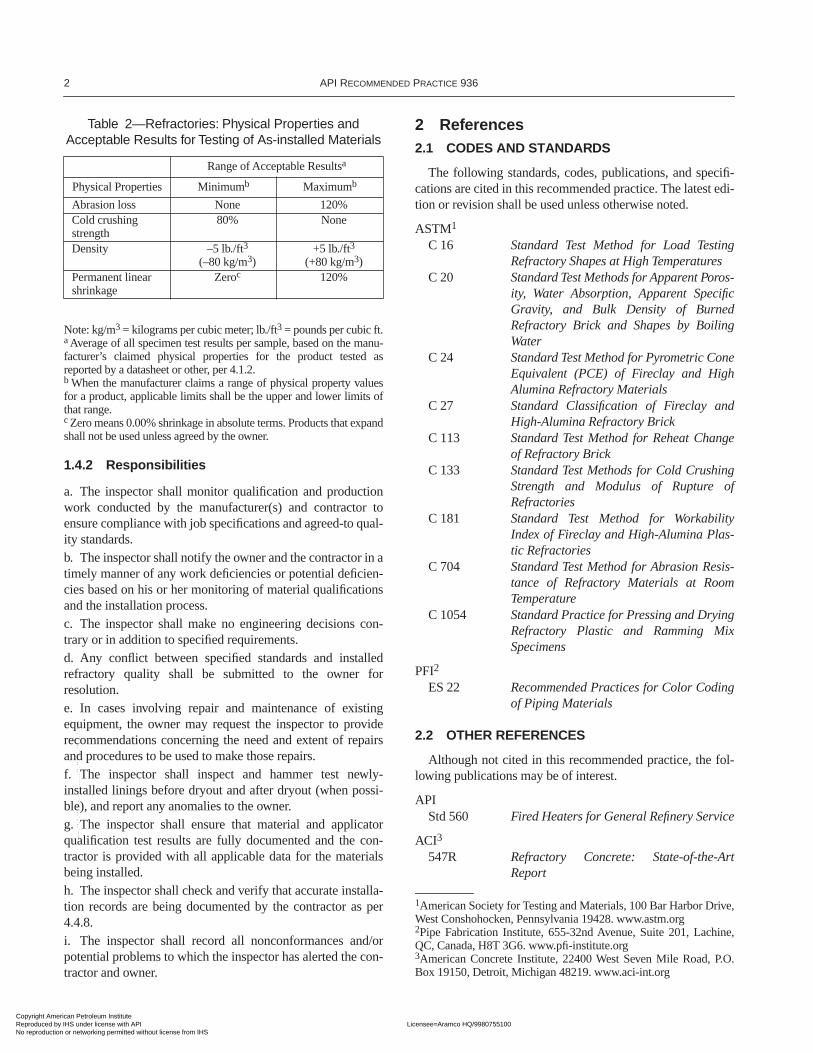
Acceptance/rejection criteria for as-installed testing:Based on criteria and procedures agreed to prior to work start,4.1.2 physical properties criteria shall be extended to accountfor field conditions as follows in Table 2.
1.4 INSPECTION
1.4.1 Qualifications of Personnel
The following qualifications of personnel apply:
a. The inspector shall have no commercial affiliations withthe contractor or manufacturer(s), unless otherwise agreed toby the owner.b. The inspector shall have a working knowledge of applica-ble standards and terms as defined in attached appendixes ofthis document.c. The inspector shall have a working knowledge of require-ments defined in this document, owner specifications and jobspecific requirements outlined by the owner or manufacturer.
Table 1—Quality Control: Key Elements
Elements Actions Objectives
Documentation (see 4.1) Owner specification and/or contractor execution plan. Define job specific work scope.Material qualification (see 4.2) Testing at Independent or manufacturer’s laboratory
Inspector directs sampling, monitors specimenpreparation and witnesses testing
a
.
Confirm that materials manufactured for the job are capable of meeting specified physical property standards.
Applicator qualification (see 4.3) Contractor demonstration of capabilities in simulated installation which is witnessed and inspected by the inspector.
Confirm that equipment and personnel are capable of installing qualified materials to specified standards.
Installation monitoring (see 4.4) Inspector monitors contractor work and test sample preparation.
Confirm that specifications, good practice andinstallation procedures are maintained.
As-installed testing (see 5.1) Inspector coordinates sampling and testing ofas-installed materials.
Confirm that installed materials meet specified physical property standards.
Pre-dryout inspection Inspector visual/hammer test inspection of applied linings.
Confirm that installed linings meet specificationstandards.
Dryout monitoring (see 6.2) If dryout by the contractor, the inspector monitors heating rates/hold times.
Confirm that agreed upon procedure is maintained.
Post dryout inspection Inspector visual/hammer test inspection of applied linings.
Confirm that installed linings meet specification standards.
Note:
a
In cases where an independent laboratory is utilized or the contractor assumes complete accountability for as-installed testing results,inspector participation may be waived or reduced by the owner.
Copyright American Petroleum Institute Reproduced by IHS under license with API Licensee=Aramco HQ/9980755100
Not for Resale, 12/03/2005 04:58:41 MSTNo reproduction or networking permitted without license from IHS
--`,`,`,`,,,```,,,,`,,``````,``-`-`,,`,,`,`,,`---
2 API R
ECOMMENDED
P
RACTICE
936
1.4.2 Responsibilities
a. The inspector shall monitor qualification and productionwork conducted by the manufacturer(s) and contractor toensure compliance with job specifications and agreed-to qual-ity standards.b. The inspector shall notify the owner and the contractor in atimely manner of any work deficiencies or potential deficien-cies based on his or her monitoring of material qualificationsand the installation process.c. The inspector shall make no engineering decisions con-trary or in addition to specified requirements.d. Any conflict between specified standards and installedrefractory quality shall be submitted to the owner forresolution.e. In cases involving repair and maintenance of existingequipment, the owner may request the inspector to providerecommendations concerning the need and extent of repairsand procedures to be used to make those repairs.f. The inspector shall inspect and hammer test newly-installed linings before dryout and after dryout (when possi-ble), and report any anomalies to the owner.g. The inspector shall ensure that material and applicatorqualification test results are fully documented and the con-tractor is provided with all applicable data for the materialsbeing installed.h. The inspector shall check and verify that accurate installa-tion records are being documented by the contractor as per4.4.8.i. The inspector shall record all nonconformances and/orpotential problems to which the inspector has alerted the con-tractor and owner.
2 References
2.1 CODES AND STANDARDS
The following standards, codes, publications, and specifi-cations are cited in this recommended practice. The latest edi-tion or revision shall be used unless otherwise noted.
ASTM
1
C 16
Standard Test Method for Load TestingRefractory Shapes at High Temperatures
C 20
Standard Test Methods for Apparent Poros-ity, Water Absorption, Apparent SpecificGravity, and Bulk Density of BurnedRefractory Brick and Shapes by BoilingWater
C 24
Standard Test Method for Pyrometric ConeEquivalent (PCE) of Fireclay and HighAlumina Refractory Materials
C 27
Standard Classification of Fireclay andHigh-Alumina Refractory Brick
C 113
Standard Test Method for Reheat Changeof Refractory Brick
C 133
Standard Test Methods for Cold CrushingStrength and Modulus of Rupture ofRefractories
C 181
Standard Test Method for WorkabilityIndex of Fireclay and High-Alumina Plas-tic Refractories
C 704
Standard Test Method for Abrasion Resis-tance of Refractory Materials at RoomTemperature
C 1054
Standard Practice for Pressing and DryingRefractory Plastic and Ramming MixSpecimens
PFI
2
ES 22
Recommended Practices for Color Codingof Piping Materials
2.2 OTHER REFERENCES
Although not cited in this recommended practice, the fol-lowing publications may be of interest.
APIStd 560
Fired Heaters for General Refinery Service
ACI
3
547R
Refractory Concrete: State-of-the-ArtReport
Table 2—Refractories: Physical Properties and Acceptable Results for Testing of As-installed Materials
Range of Acceptable Results
a
Physical Properties Minimum
b
Maximum
b
Abrasion loss None 120%Cold crushing strength
80% None
Density –5 lb./ft
3
(–80 kg/m
3
)+5 lb./ft
3
(+80 kg/m
3
)Permanent linear shrinkage
Zero
c
120%
Note: kg/m
3
= kilograms per cubic meter; lb./ft
3
= pounds per cubic ft.
a
Average of all specimen test results per sample, based on the manu-facturer’s claimed physical properties for the product tested asreported by a datasheet or other, per 4.1.2.
b
When the manufacturer claims a range of physical property valuesfor a product, applicable limits shall be the upper and lower limits ofthat range.
c
Zero means 0.00% shrinkage in absolute terms. Products that expandshall not be used unless agreed by the owner.
1
American Society for Testing and Materials, 100 Bar Harbor Drive,West Conshohocken, Pennsylvania 19428. www.astm.org
2
Pipe Fabrication Institute, 655-32nd Avenue, Suite 201, Lachine,QC, Canada, H8T 3G6. www.pfi-institute.org
3
American Concrete Institute, 22400 West Seven Mile Road, P.O.Box 19150, Detroit, Michigan 48219. www.aci-int.org
Copyright American Petroleum Institute Reproduced by IHS under license with API Licensee=Aramco HQ/9980755100
Not for Resale, 12/03/2005 04:58:41 MSTNo reproduction or networking permitted without license from IHS
--`,`,`,`,,,```,,,,`,,``````,``-`-`,,`,,`,`,,`---
R
EFRACTORY
I
NSTALLATION
Q
UALITY
C
ONTROL
G
UIDELINES
—I
NSPECTION
AND
T
ESTING
M
ONOLITHIC
R
EFRACTORY
L
ININGS
AND
M
ATERIALS
3
ASME
4
Boiler and Pressure Vessel Code, Section I, Power Boilers,Section VIII, Pressure Vessels, Division 1
ASTM
1
A 167
Standard Specification for Stainless andHeat-Resisting Chromium-Nickel SteelPlate, Sheet, and Strip
A 176
Standard Specification for Stainless andHeat-Resisting Chromium Steel Plate,Sheet, and Strip
A 576
Standard Specification for Steel Bars, Car-bon, Hot-Wrought, Special Quality
A 580/A 580M
Standard Specification for Stainless SteelWire
A 743/A 743M
Standard Specification for Castings, Iron-Chromium, Iron-Chromium-Nickel, Corro-sion Resistant, for General Application
A 1011/
Standard Specification for Steel, Sheet and
A 1011M
Strip, Carbon, Structural, High-StrengthLow-Alloy, and High-Strength Low Alloywith Improved Formability
C 71
Standard Terminology Relating toRefractory
C 109/C 109M
Standard Test Method for
CompressiveStrength of Hydraulic Cement Mortars(Using 2-in. or [50-mm] Cube Specimens)
C 134
Standard Test Methods for Size, Dimen-sional Measurements, and Bulk Density ofRefractory Brick and Insulating Firebrick
C 179
Standard Test Method for Drying and Fir-ing Linear Change of Refractory Plasticand Ramming Mix Specimens
C 201
Standard Test Method for Thermal Con-ductivity of Refractories
C 401
Standard Classification of Alumina andAlumina-Silicate Castable Refractories
C 417
Standard Test Method for Thermal Con-ductivity of Unfired MonolithicRefractories
C 673
Standard Classification of Fireclay andHigh-Alumina Plastic Refractories andRamming Mixes
C 832
Standard Test Method of Measuring theThermal Expansion and Creep of Refracto-ries Under Load
C 860
Standard Practices for Determining theConsistency of Refractory Castable Usingthe Ball-in-Hand Test
C 865
Standard Practice for
Firing RefractoryConcrete Specimens
C 914
Standard Test Method for Bulk Density andVolume of Solid Refractories by WaxImmersion
C 1113
Standard Test Method for Thermal Conduc-tivity of Refractories by Hot Wire (PlatinumResistance Thermometer Technique)
C 1171
Standard Test Method for QuantitativelyMeasuring the Effect of Thermal Shockand Thermal Cycling on Refractories
C 1445
Standard Test Method for Measuring Con-sistency of Castable Refractory Using aFlow Table
C 1446
Standard Test Method for Measuring theConsistency and Working Time of Self-Flowing Castable Refractories
E 177
Standard Practice for Use of the TermsPrecision and Bias in ASTM Test Methods
E 691
Standard Practice for Conducting anInterlaboratory Study to Determine thePrecision of a Test Method
Harbison-Walker Handbook of Refractory Practices,
1stEdition, 1992
SSPC
5
SP 3
Power Tool Cleaning
3 Definitions
For the purposes of this recommended practice, the follow-ing definitions apply:
3.1 applicator qualification testing:
Pre-installationsimulation of production work that is sampled and tested aswell as visually inspected to verify that application equip-ment and personnel are capable of meeting specified qualitystandards.
3.2 as-installed testing:
Testing of refractory materialssampled from the installation to confirm that they meet speci-fied physical property standards.
3.3 contractor:
The party or parties responsible forinstalling refractory in the equipment of the owner.
3.4 erosion service:
Installations of refractories in fluidsolids units, such as transfer and overhead lines, cyclone lin-ings, and deflector shields, in which erosion resistance is adetermining feature of lining service life.
3.5 heating contractor:
Contractor or subcontractorwho specializes in the dryout of monolithic refractory linings.
3.6 hexalt anchors:
Metallic anchor used as an alterna-tive to hexmesh in thin layer, erosion resistant linings; forexample, S-Bar, Hexcel, Curl and Tacko anchors, and the like.
4
ASME International, 345 East 47th Street, New York, New York10017. www.asme.org
5
Society for Protective Coatings, 4400 Fifth Avenue, Pittsburgh,Pennsylvania 15213-2683. www.sspc.org
Copyright American Petroleum Institute Reproduced by IHS under license with API Licensee=Aramco HQ/9980755100
Not for Resale, 12/03/2005 04:58:41 MSTNo reproduction or networking permitted without license from IHS
--`,`,`,`,,,```,,,,`,,``````,``-`-`,,`,,`,`,,`---
4 API R
ECOMMENDED
P
RACTICE
936
3.7 independent laboratory:
A refractory testing facil-ity not affiliated with the manufacturer or contractor.
3.8 inspector:
The party or individual whom the ownerhas contracted or otherwise designated to monitor refractoryinstallation work being conducted by the contractor and sup-plying material manufacturer(s).
3.9 manufacturer:
The party or parties supplying therefractory lining materials to be installed in the equipment ofthe owner.
3.10 material qualification testing:
Pre-installationtesting of refractory materials in which production lots ofrefractories manufactured for a specific installation are sam-pled and tested to confirm that they meet specified physicalproperty requirements.
3.11 monolithic refractories:
Castable or plastic refrac-tories applied by casting, gunning, or hand/ram packing toform monolithic lining structures.
3.12 owner:
The proprietor of equipment who hasengaged one or more parties to install or repair refractory inthe equipment.
3.13 production run:
The quantity of refractory havingthe same formulation that is prepared in an uninterruptedmanufacturing operation.
3.14 test sample:
That quantity of refractory taken froma single container or installation sequence that is used tomake a complete set of test specimens to determine compres-sive strength, erosion resistance, density, linear change, and/or any other physical property determinations.
3.15 test specimen:
Individual cubes, bars, or plate testpieces used for physical property testing. Physical propertytest results for a sample are usually expressed as the averageof two or more specimens made up from the same sample.
Additional terms and definitions applicable to this docu-ment and the work that it covers are contained as a glossary inAppendix A.
4 Work Execution
4.1 DOCUMENTATION
Supplemental to this document, the owner shall prepare adetailed specification and/or refer to the contractor to preparea detailed execution plan subject to the owner’s approval.These supplemental documents shall be prepared and agreedto in full before work starts. Items covered shall include thefollowing:
4.1.1 Design Details
The following design details apply:
a. Lining products, thickness, method of application, andextent of coverage.
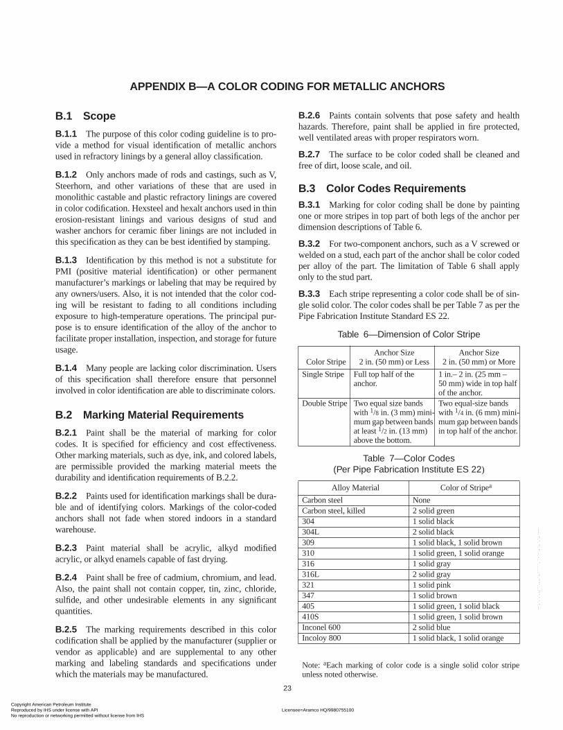
b. Anchor materials, geometry, and layout. Suggested colorcoding for metallic anchors is given in Appendix B.c. Surface preparation, welding procedures, and anchorattachment integrity.d. When used, details of metal fiber reinforcement includingdimensions, concentration, type, and metallurgy.
4.1.2 Quality Standards
The following quality standards apply:
a. Physical property requirements to be used for qualificationand installation quality control by specific product and loca-tion where it is being utilized. These requirements shall be inaccordance with manufacturer’s datasheet claims or compli-ance datasheets unless amended by prior agreement withowner.b. Sampling procedures as applicable to designation of prod-ucts to be used in either erosion service or other service asdefined in 4.2.4.c. Required lining thickness tolerances and criteria for ham-mer test and allowable cracking in the applied lining.
4.1.3 Execution Details
The following execution details apply:
a. Installation and quality control procedures.b. Designation of responsible parties.c. Curing and dryout procedures.
4.2 MATERIAL QUALIFICATION TESTING
4.2.1 All refractories to be installed by gunning, casting, orhand/ram packing shall be tested to comply with specifiedphysical property requirements as determined in 4.1.2.a.Tested physical properties shall be density, permanent linearchange (PLC), and cold crushing strength (CCS) or abrasionresistance (where applicable) per 5.2.
4.2.2 The contractor shall arrange for testing at either anindependent laboratory or the manufacturer’s plant, and directthe work to assure that mixing techniques, water contents,ambient temperatures, mix temperatures, and so on, ade-quately represent those needed for production installation. Theoperative testing party is responsible for conduct of sampling,specimen preparation, testing, and documentation of results.
4.2.3 The contractor shall inform the owner of testingarrangements and timing so that the owner may notify theinspector to witness or spot check the testing. When engagedas a witness, the inspector shall select the container to betested and observe all sampling, specimen preparation, andtesting. In cases where an independent laboratory is utilizedor the contractor assumes complete accountability for as-installed testing results, inspector participation may bewaived or reduced by the owner.
Copyright American Petroleum Institute Reproduced by IHS under license with API Licensee=Aramco HQ/9980755100
Not for Resale, 12/03/2005 04:58:41 MSTNo reproduction or networking permitted without license from IHS
--`,`,`,`,,,```,,,,`,,``````,``-`-`,,`,,`,`,,`---
REFRACTORY INSTALLATION QUALITY CONTROL GUIDELINES—INSPECTION AND TESTING MONOLITHIC REFRACTORY LININGS AND MATERIALS 5
4.2.4 Based on the use designation determined by 4.1.2,testing frequency shall be as follows:
a. Erosion service: one sample per pallet or less from eachproduction run.b. Other service: one sample per three pallets or less fromeach production run.
4.2.5 As directed by the contractor, test sample refractoriesshall be mixed and formed using metal or plastic forms at therequired specimen dimensions, or larger dimensions and thencut to the required dimensions after 24-hour cure:
a. For vibration cast installations, vibration may be used inthe forming of the test specimens. b. For pump cast installations, refractory shall be poured intoforms. c. For hand pack installations, refractory shall be handpacked. d. For gunned installations, refractory shall be gunned orcast, alternatively specimens may be hand packed subject toprior approval by the owner. e. Plastic and other ramming refractories may be formedusing a mallet or handheld pneumatic rammer. Specimen for-mation using a pneumatic or ramming press, as described byASTM C 1054, is not permitted.
4.2.6 Every refractory shall be applied within 4 months ofinitial qualification tests, or 3 months of a succeeding qualifi-cation test per the procedures herein. If the initial qualifica-tion period is exceeded, the respective batch may berequalified. Requalification permits usage for an additional 3months after each succeeding qualification test up to the man-ufacturer’s recommended shelf life.
4.2.7 In the event a sample fails to meet specified results, itmay be retested. The retest shall be conducted using the sametesting facility and inspection, or at a different facility subjectto the owner’s approval.
4.3 APPLICATOR QUALIFICATION TESTING
Prior to installation, the contractor shall take the materialsqualified for the job, and, using equipment and personnel tobe utilized for the installation work, demonstrate that speci-fied quality standards can be met. This shall be done by simu-lating the installation work, and sampling and testing theapplied materials as follows:
4.3.1 Pneumatic Gunning
A test panel shall be prepared by each nozzleman/gunoperator team for each refractory being installed with prepa-ration and examination as follows:
a. A test panel shall be fabricated measuring 24 in. × 24 in.(600 mm × 600 mm) with thickness and anchors the same asthe actual installation job.
b. The test panel shall be inclined 45 degrees above the hori-zontal and supported on a frame so that the panel’s midpointis approximately 6 ft (1.9 m) above ground level. The nozzle-man/gun operator team shall demonstrate their abilities bygunning the test panel in this inclined position.c. The test panel shall be constructed with a removable backfor visual inspection of the castable. The panel shall also besectioned and cut surfaces inspected for voids, laminations,non-uniformities, and rebound entrapment. Sectioning orbreaking of the panel is permitted 18 hours after completionof the panel unless otherwise directed by the owner.d. Test specimens (number and type per 5.2) shall be cutfrom each panel and tested for compliance to 4.1.2 physicalproperty standards for density, permanent linear change, andcold crushing strength or abrasion resistance.e. Satisfactory examination and test results per 4.3.1,items c – d, will serve to qualify the mixing and installa-tion procedures and the nozzleman/gun operator teams. Nonozzleman or gun operator shall gun refractory materialsuntil they are qualified.
4.3.2 Casting
A mock-up simulating the most difficult piece of the instal-lation work or the size/shape agreed to in the documentationphase (per 4.1.3) shall be completed, and applied materialssampled and tested prior to actual installation work per thefollowing:
a. The mock-up shall simulate forming and placement proce-dures, installation of refractory around nozzle protrusions,and fit-up tolerances if work involves lining of sections to befit-up at a later date.b. For vibration cast installations, the mock-up shall demon-strate the adequacy of vibration equipment and attachmentmethod of vibrators, along with general installation proce-dures, such as mixing, handling/delivery to lining cavity andassociated quality control requirements.c. For pouring and pump cast installations, only vibrationthat will be used in the actual installation shall be allowed inthe mock-up.d. Test specimens (number and type per 5.2.1) shall be pre-pared for materials sampled from the mixes prepared forcasting in the mock-up and formed in molds using the samelevel of agitation as the mock-up. Specimens shall be testedper 5.2 and 5.3 for density, permanent linear change, and coldcrushing strength or abrasion resistance.e. Refractory cast in the mock-up shall be cured for 12 hoursminimum and then stripped of forms for visual inspectiononly. The applied lining shall be homogeneous and free ofsegregation and shall meet specified tolerances.f. Satisfactory examination and test results per 4.3.2, items c– d, will serve to qualify the mixing and installation proce-dures as well as mix water levels. The applicator shall not cast
Copyright American Petroleum Institute Reproduced by IHS under license with API Licensee=Aramco HQ/9980755100
Not for Resale, 12/03/2005 04:58:41 MSTNo reproduction or networking permitted without license from IHS
--`,`,`,`,,,```,,,,`,,``````,``-`-`,,`,,`,`,,`---
6 API RECOMMENDED PRACTICE 936
refractory linings until he or she has completed a satisfactorymock-up test.
4.3.3 Placement of Thin Layer, Erosion Resistant Refractories
A test panel 12 in. × 12 in. × 3/4 or 1 in. (300 mm × 300 mm× 20 or 25 mm), shall be packed by each applicator and exam-ined as follows:
a. Panel thickness shall be the same as the lining to beinstalled. Mixing and application techniques, for example,pneumatic ramming, hand packing, orientation sidewall oroverhead, and the like, shall also be the same as theinstallation.b. Hexmesh or hexalt anchoring system (as the case may be)shall be attached to a backing plate such that the backingplate may be removed and the applied refractory lining exam-ined from the backside. Examination of the panel may beperformed immediately after ramming, or within 24 hours, asdirected by the owner.c. Test specimens shall be prepared for materials sampledfrom the mixes applied and formed in molds, using the sameplacement method as the test panel. Specimens shall be testedper 5.2 and 5.3 for density, permanent linear change, andabrasion resistance.d. Satisfactory examination and test results per 4.3.3, items b– c, shall serve to qualify the mixing and installation proce-dures as well as mix water levels. The applicator shall notapply refractory linings until qualified.
4.3.4 Thick Layer, Plastic Installations
A test panel shall be pneumatically ram packed by eachapplicator with preparation and examination as follows:
a. The test panel shall be 24 in. × 12 in. (600 mm × 300 mm)with an applied lining thickness and anchorage that are thesame as the actual installation. Anchors shall be attached suchthat the backing plate may be removed and applied refractoryexamined from the back side. The backing plate shall becoated with a parting agent to facilitate removal from theapplied refractory.b. Test panel refractory shall be installed by pneumatic ram-ming in a manner simulating the actual installation (in otherwords, sidewall or overhead).c. After refractory installation is completed, the test panelbacking plate shall be removed immediately and examinedfor consolidation and voids.d. No additional test specimens and testing are required aslong as material qualification results and applied refractoryworkability is satisfactory.e. Satisfactory results will serve to qualify the equipment,techniques, and applicator. No applicator shall ram packrefractory materials until he or she has been qualified.
4.3.5 Contractor Responsibilities
The following list provides contractor responsibilities:
a. Scheduling of Material Qualification Tests and delivery ofthose materials and test results to the site.b. Scheduling and execution of work to qualify all equipmentand personnel needed to complete installation work, includ-ing documentation and verification by the inspector.c. Preparation and identification of all testing samples andtimely delivery to the testing laboratory.d. Advance notification to the owner of the time and locationwhere work will take place so that this information can bepassed on to the inspector.
4.4 INSTALLATION
4.4.1 Packaging and Storage
The following applies to packaging and storage:
a. Hydraulic bonded, castable refractories shall be packagedin moisture-proof bags with the product name, batch number,and date of manufacture clearly shown. Bag weight shall bemarked, and the weight of refractory in the bag shall not devi-ate from this value by more that ± 2%.b. Chemical setting refractories shall be packaged in heat-sealed plastic to assure vapor-tight enclosure. Mechanicalprotection shall be provided by cardboard, rigid plastic, ormetal outside containers. Each container shall be marked withthe production batch number. Packages with broken seals orvariation in workability shall be subject to requalification.c. Refractory materials shall be stored in a weather-protectedarea. Time limits for material qualification tests (see 4.2.6)shall set refractory shelf life. If the manufacturer’s shelf liferecommendations are more stringent, the manufacturer’srestrictions shall apply.d. Water used for mixing in the refractory shall be potable.
4.4.2 Application Temperature
The following applies to application temperature:
a. The temperature of the air and shell at the installation siteshall be between 50°F (10°C) minimum and 90°F (32°C)maximum during refractory installation and the 24 hoursthereafter.b. For cold weather conditions, heating and/or external insu-lation may be used to maintain temperatures above theminimum requirement.c. For hot weather conditions, shading, water spraying and/or air conditioning may be used to maintain temperaturesbelow the maximum requirement.d. Temperature limits for refractory and mix water shall be inaccordance with the manufacturer’s requirements. In theabsence of manufacturer’s mix temperature limits, mix tem-perature shall be between 60°F – 80°F (15°C – 27°C).
Copyright American Petroleum Institute Reproduced by IHS under license with API Licensee=Aramco HQ/9980755100
Not for Resale, 12/03/2005 04:58:41 MSTNo reproduction or networking permitted without license from IHS
--`,`,`,`,,,```,,,,`,,``````,``-`-`,,`,,`,`,,`---
REFRACTORY INSTALLATION QUALITY CONTROL GUIDELINES—INSPECTION AND TESTING MONOLITHIC REFRACTORY LININGS AND MATERIALS 7
4.4.3 Gunning
The following applies to gunning:
a. Pre-wet the refractory by mixing with water prior to charg-ing into the gun to reduce dusting and segregation, while atthe same time avoiding plugging in the feed hose. Optimumamount and mixing of the pre-wetted material shall be per theapplicator qualification testing. Use of pre-wet may bewaived for some products, subject to the manufacturer’s rec-ommendations and the owners’ approval.b. Gunning equipment shall provide a smooth and continu-ous supply of water and material without causinglaminations, voids, or rebound entrapment. Shotboards orperpendicular edge cuts shall be used to terminate work areas.When stoppages greater than 30 minutes are encountered orinitial set is determined by the inspector, only full thicknesslining shall be retained.c. Start gunning at the lowest elevation, building up the liningthickness gradually over an area of not more than 10 ft2 (1 m2)to full thickness and working in an upward direction to mini-mize the inclusion of rebound. Rebound material shall not bereused.d. Downhand gunning beyond 30 degrees below horizontal isprohibited unless agreed to otherwise by the owner. Therefractory shall be placed by an alternative placement tech-nique such as casting, hand packing, or repositioning to avoidthe downhand orientation.e. Shot board height and depth gauges shall be used for thick-ness measurement guides. After gunning and confirmation ofsufficient coverage, the refractory shall be trimmed (cut back)in a timely manner with a serrated trowel or currycomb. Cutback shall be performed when the surface is not damaged bythe cut back techniques, and before initial set occurs. “Flash-ing” or interrupted build-up of lining thickness is not permittedafter initial set as defined by the surface being exposed formore than 20 minutes or becoming dry to the touch.
4.4.4 Casting
The following applies to casting:
a. Forming shall be sufficiently strong to support the hydrau-lic head of wet refractory that it will retain and to resist anymechanical loads, such as vibration. The forms shall bewaterproof and leak free. Dimensional tolerances shall meetspecified requirements. A release agent such as grease, formrelease, or wax shall be used to facilitate stripping of theforms.b. Refractory shall be mixed using procedures, equipment,and water levels demonstrated in material and applicatorqualification tests. For vibration casting in pipe sections,mixer capacity should be sufficient to facilitate placementwith no more than 10 minutes between successive mixbatches. For pump casting, mixer capacity shall be sufficient
to allow for continuous pump operation without stops andstarts to wait for material.c. For vibration casting, two or more rotary vibrators shall bemounted externally on the equipment or component to belined. Vibrators shall have adequate force to move and con-solidate the material being vibrated. Each vibrator shall beindependently controlled to focus vibration and prevent seg-regation due to over vibration. The method of vibratorattachment shall be subject to the owner’s approval.d. For pouring or pump casting, submersion vibrators or rod-ding may be used to aid refractory flow and filling of theformed enclosure.e. The newly applied lining shall cure per the manufacturer’srecommendation (minimum of 24 hours) before moving thepiece or stripping the forms. Curing shall be per 6.1.2.
4.4.5 Placement of Thin Layer, Erosion Resistant Linings
The following applies to thin layer, erosion resistant linings:
a. All air-setting phosphate bonded refractories shall bemixed in a rotating paddle mixer, such as those manufacturedby Hobart. The mixer shall have steel paddles and bowls.Aluminum paddles and bowls shall not be used due to theirpotential to react with the acid component in the refractory.Mixing shall be in strict accordance with the manufacturer’srecommended procedures using water levels determined dur-ing material qualification testing. Adjustments in water levelsare permitted after application qualification tests, withowner’s approval.b. All heat-setting plastic refractories shall be installed at themanufactured consistency. Field water addition or recondi-tioning is not permitted. Any reconditioning must beperformed by the manufacturer under controlled plant condi-tions, and the reconditioned material shall be fully requalifiedper 4.2. The manufacturer shall measure the workabilityindex on plastic refractories per ASTM C 181 seven daysafter manufacture and provide this to the contractor. The man-ufacturer shall also provide the minimum workability indexfor each plastic refractory supplied, for suitable installation.c. Refractory shall be applied using a handheld, reciprocat-ing pneumatic rammer, rubber mallet, and/or wood block asdemonstrated in applicator qualification tests. During place-ment, refractory shall be fully compacted in and around theanchor supports to form a homogeneous lining-structure freeof voids and laminations.d. Once consolidated, overfill shall be removed flush with thetops of the hexmesh or hexalt anchors using a trowel or curry-comb. The surface shall then be tamped, as necessary, toremove imperfections such as surface tearing and pull awaydefects.e. Water slicking of the lining surface is not permitted. Waterused to clean and lubricate tools shall be dried off prior to useon the refractory.
Copyright American Petroleum Institute Reproduced by IHS under license with API Licensee=Aramco HQ/9980755100
Not for Resale, 12/03/2005 04:58:41 MSTNo reproduction or networking permitted without license from IHS
--`,`,`,`,,,```,,,,`,,``````,``-`-`,,`,,`,`,,`---
8 API RECOMMENDED PRACTICE 936
4.4.6 Thick Layer, Plastic Installations
The following applies to thick layer, plastic installations:
a. All heat-setting plastic refractories shall be installed at themanufactured consistency. Field water addition or recondition-ing is not permitted. Any reconditioning must be performed bythe manufacturer under controlled plant conditions, and thereconditioned material shall be fully requalified per 4.2.b. Refractory shall be removed from the container/plasticwrap only when ready for application. Contents shall beplaced on a clean surface for cutting and/or separating precutslices. This work surface shall be maintained to avoid con-taminating fresh refractory with dried-out material fromprevious cutting or separating operations.c. Refractory shall be ram packed in successive handful-sized clumps using a handheld, reciprocating pneumatic ram-mer, fully consolidating each clump into a uniform mass andcompacting the material in and around the anchor supports toform a homogeneous lining structure free of voids and lami-nations that is greater than the desired lining thickness.d. Once placed and consolidated, the lining shall be trimmedto the desired lining thickness using a trowel or currycomb.Cutback material may be reused if workability characteristicsare not diminished. Under no circumstances shall dry orcrumbly material be installed.e. The trimmed surface shall then be tamped, as necessary, toremove imperfections such as surface tearing and pull awaydefects. Water slicking of the lining surface is not permitted.
4.4.7 Metal Fiber Reinforcement
a. Metal fiber reinforcement shall be used only when speci-fied by the owner. Fiber additions shall be uniformlydispersed in the castable without agglomeration.b. The procedure for adding metal fibers during lining instal-lation shall be as follows:
1. Load castable into mixer and pre-mix.2. Add pre-wet or mixing water.3. Using a dispersing device, such as 1/2 in. (13 mm)hardware mesh, sieve fibers into castable with mixeroperating.
c. Specific details of fiber dimensions, concentration, andmetallurgy shall be covered in documentation per 4.1.1. Fiberconcentrations typically range 1 – 4 wt percent with effectivediameters of 0.010 in. – 0.022 in. (0.3 mm – 0.6 mm) andlengths 3/4 or 1 in. (19 mm or 25 mm).
4.4.8 Contractor Responsibilities
a. Advance agreement with the owner on all installationdetails as defined in 4.1 and as outlined in approved writtenexecution plan.b. Execution of installation work, including preparation ofas-installed samples per 5.1 for density, permanent linearchange, and cold crushing strength or abrasion resistance test-
ing, and timely delivery of those samples to the designatedtest laboratory.c. Inspector verified documentation of installation records,including these:
1. Product(s) being applied.2. Pallet numbers and location where applied.3. Installation crew members (designating nozzleman/gun operator when gunning).4. Mixing and/or gunning equipment utilized.5. Fiber and water percentages.6. Mixing details including time, temperature, and agingtime (if gunned).7. Location and identity of samples taken for installationquality control.
d. Accountability for installed refractories meeting specifiedstandards, including as-installed testing results as defined in5.1.4, and lining thickness tolerance limits as defined by 4.1.2.
4.4.9 Organic fibers used to facilitate moisture removal ofrefractory linings during dryout shall be used with ownerapproval. Fiber additions shall be performed during manufac-ture of the castable or plastic refractory.
5 Testing5.1 AS-INSTALLED TESTING
5.1.1 Gunning
a. A minimum of one sample of applied refractory shall begunned by each gunning crew per material per shift using a“wire mesh basket” which is about 12 in. × 12 in. (300 mm ×300 mm) and at least 4 in. (100 mm) deep. The basket, con-structed of 1/2 in. (13 mm) wire mesh, shall be supportedbetween anchors on the wall where the lining application isproceeding, filled, and immediately removed. All looserefractory or rebound material shall be removed from the areawhere the basket was placed during sample preparation. Therequired test specimens (per 5.2.1) shall be prepared by dia-mond saw-cutting the specimens from refractory applied inthe basket and testing per 5.3.b. Alternatively, panels with enclosed sides may be used inplace of the wire baskets if the panel dimensions are at least18 in. × 18 in. × 4 in. (450 mm × 450 mm × 100 mm) and testspecimens are cut from the center of the panels to avoid pos-sible rebound traps along the sides of the panels.
5.1.2 Casting
A minimum of one sample shall be cast by each mixingcrew per material per shift. Samples may be formed directlyinto test specimens from the refractory being installed or castinto larger forms and cut to the required specimen dimensionsafter curing. Vibration may be used in casting of samples asapplicable to simulate installation work. The required speci-mens per 5.2.1 shall be tested per 5.3.
Copyright American Petroleum Institute Reproduced by IHS under license with API Licensee=Aramco HQ/9980755100
Not for Resale, 12/03/2005 04:58:41 MSTNo reproduction or networking permitted without license from IHS
--`,`,`,`,,,```,,,,`,,``````,``-`-`,,`,,`,`,,`---
REFRACTORY INSTALLATION QUALITY CONTROL GUIDELINES—INSPECTION AND TESTING MONOLITHIC REFRACTORY LININGS AND MATERIALS 9
5.1.3 Placement of Thin Layer, Erosion Resistant Linings and Plastics
A minimum of one sample shall be packed by each appli-cator per material per shift. Samples shall be formed directlyinto test specimens (abrasion plates and linear change bars)from the refractory being installed by the ramming techniqueused for the installation. The required specimens per 5.2.1shall be tested per 5.3.
5.1.4 Acceptance/Rejection
For each sample, the average physical properties of as-installed tests shall meet the criteria defined in 1.3.3 and thefollowing:
a. Inspector-verified records shall be kept by the contractorto identify samples and the areas of installed lining that theyrepresent.b. Failure to meet the preceding criteria shall be cause forrejection of the area of the lining that the sample represents.c. In the event of disagreement over installed refractory qual-ity, core samples may be taken from the questionable area ofapplied lining and retested using the same criteria.
5.2 TEST SPECIMEN PREPARATION
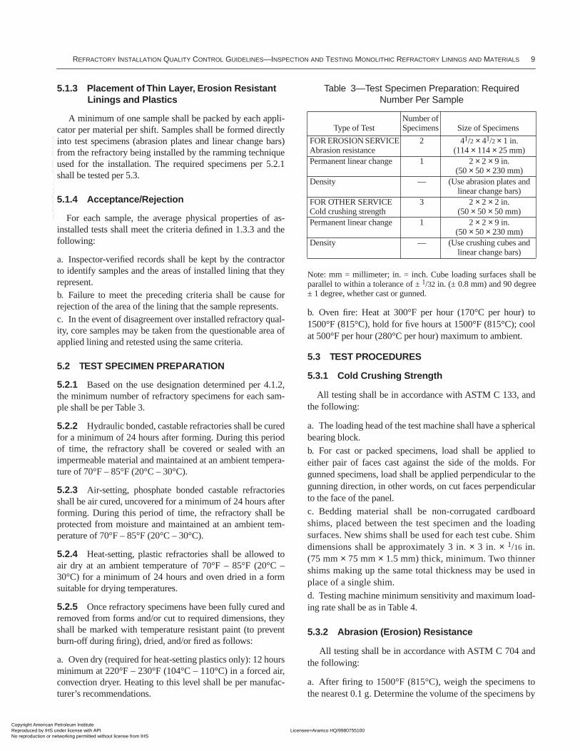
5.2.1 Based on the use designation determined per 4.1.2,the minimum number of refractory specimens for each sam-ple shall be per Table 3.
5.2.2 Hydraulic bonded, castable refractories shall be curedfor a minimum of 24 hours after forming. During this periodof time, the refractory shall be covered or sealed with animpermeable material and maintained at an ambient tempera-ture of 70°F – 85°F (20°C – 30°C).
5.2.3 Air-setting, phosphate bonded castable refractoriesshall be air cured, uncovered for a minimum of 24 hours afterforming. During this period of time, the refractory shall beprotected from moisture and maintained at an ambient tem-perature of 70°F – 85°F (20°C – 30°C).
5.2.4 Heat-setting, plastic refractories shall be allowed toair dry at an ambient temperature of 70°F – 85°F (20°C –30°C) for a minimum of 24 hours and oven dried in a formsuitable for drying temperatures.
5.2.5 Once refractory specimens have been fully cured andremoved from forms and/or cut to required dimensions, theyshall be marked with temperature resistant paint (to preventburn-off during firing), dried, and/or fired as follows:
a. Oven dry (required for heat-setting plastics only): 12 hoursminimum at 220°F – 230°F (104°C – 110°C) in a forced air,convection dryer. Heating to this level shall be per manufac-turer’s recommendations.
b. Oven fire: Heat at 300°F per hour (170°C per hour) to1500°F (815°C), hold for five hours at 1500°F (815°C); coolat 500°F per hour (280°C per hour) maximum to ambient.
5.3 TEST PROCEDURES
5.3.1 Cold Crushing Strength
All testing shall be in accordance with ASTM C 133, andthe following:
a. The loading head of the test machine shall have a sphericalbearing block.
b. For cast or packed specimens, load shall be applied toeither pair of faces cast against the side of the molds. Forgunned specimens, load shall be applied perpendicular to thegunning direction, in other words, on cut faces perpendicularto the face of the panel.
c. Bedding material shall be non-corrugated cardboardshims, placed between the test specimen and the loadingsurfaces. New shims shall be used for each test cube. Shimdimensions shall be approximately 3 in. × 3 in. × 1/16 in.(75 mm × 75 mm × 1.5 mm) thick, minimum. Two thinnershims making up the same total thickness may be used inplace of a single shim.
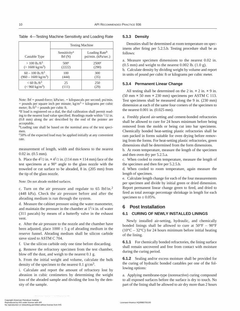
d. Testing machine minimum sensitivity and maximum load-ing rate shall be as in Table 4.
5.3.2 Abrasion (Erosion) Resistance
All testing shall be in accordance with ASTM C 704 andthe following:
a. After firing to 1500°F (815°C), weigh the specimens tothe nearest 0.1 g. Determine the volume of the specimens by
Table 3—Test Specimen Preparation: Required Number Per Sample
Type of TestNumber of Specimens Size of Specimens
FOR EROSION SERVICE Abrasion resistance
2 41/2 × 41/2 × 1 in.(114 × 114 × 25 mm)
Permanent linear change 1 2 × 2 × 9 in. (50 × 50 × 230 mm)
Density — (Use abrasion plates and linear change bars)
FOR OTHER SERVICE Cold crushing strength
3 2 × 2 × 2 in. (50 × 50 × 50 mm)
Permanent linear change 1 2 × 2 × 9 in. (50 × 50 × 230 mm)
Density — (Use crushing cubes and linear change bars)
Note: mm = millimeter; in. = inch. Cube loading surfaces shall beparallel to within a tolerance of ± 1/32 in. (± 0.8 mm) and 90 degree± 1 degree, whether cast or gunned.
Copyright American Petroleum Institute Reproduced by IHS under license with API Licensee=Aramco HQ/9980755100
Not for Resale, 12/03/2005 04:58:41 MSTNo reproduction or networking permitted without license from IHS
--`,`,`,`,,,```,,,,`,,``````,``-`-`,,`,,`,`,,`---
10 API RECOMMENDED PRACTICE 936
measurement of length, width and thickness to the nearest0.02 in. (0.5 mm).
b. Place the 41/2 in. × 41/2 in. (114 mm × 114 mm) face of thetest specimens at a 90° angle to the glass nozzle with thetroweled or cut surface to be abraded, 8 in. (205 mm) fromthe tip of the glass nozzle.
Note: Do not abrade molded surfaces.
c. Turn on the air pressure and regulate to 65 lbf/in.2
(448 kPa). Check the air pressure before and after theabrading medium is run through the system.
d. Measure the cabinet pressure using the water manometer,and maintain the pressure in the chamber at 11/4 in. of water(311 pascals) by means of a butterfly valve in the exhaustvent.
e. After the air pressure to the nozzle and the chamber havebeen adjusted, place 1000 ± 5 g of abrading medium in thereserve funnel. Abrading medium shall be silicon carbidesieve sized to ASTM C 704.
f. Use the silicon carbide only one time before discarding.
g. Remove the refractory specimen from the test chamber,blow off the dust, and weigh to the nearest 0.1 g.
h. From the initial weight and volume, calculate the bulkdensity of the specimen to the nearest 0.1 g/cm3.
i. Calculate and report the amount of refractory lost byabrasion in cubic centimeters by determining the weightloss of the abraded sample and dividing the loss by the den-sity of the sample.
5.3.3 Density
Densities shall be determined at room temperature on spec-imens after firing per 5.2.5.b. Testing procedure shall be asfollows:
a. Measure specimen dimensions to the nearest 0.02 in.(0.5 mm) and weight to the nearest 0.002 lb. (1.0 g).b. Calculate density by dividing weight by volume and reportin units of pound per cubic ft or kilograms per cubic meter.
5.3.4 Permanent Linear Change
All testing shall be determined on the 2 in. × 2 in. × 9 in.(50 mm × 50 mm × 230 mm) specimens per ASTM C 113.Test specimens shall be measured along the 9 in. (230 mm)dimension at each of the same four corners of the specimen tothe nearest 0.001 in. (0.025 mm).
a. Freshly placed air-setting and cement-bonded refractoriesshall be allowed to cure for 24 hours minimum before beingremoved from the molds or being cut into bar specimens.Chemically bonded heat-setting plastic refractories shall beram packed in forms suitable for oven drying before remov-ing from the forms. For heat-setting plastic refractories, greendimensions shall be determined from the form dimensions.b. At room temperature, measure the length of the specimenand then oven dry per 5.2.5.a. c. When cooled to room temperature, measure the length ofthe specimen and then fire per 5.2.5.b.d. When cooled to room temperature, again measure thelength of specimen. e. Calculate length change for each of the four measurementsper specimen and divide by initial green or dried dimension.Report permanent linear change green to fired, and dried tofired as total average percentage shrinkage in length for eachspecimen to ± 0.05%.
6 Post Installation6.1 CURING OF NEWLY INSTALLED LININGS
Newly installed air-setting, hydraulic, and chemicallybonded linings shall be allowed to cure at 50°F – 90°F(10°C – 32°C) for 24 hours minimum before initial heatingof the lining.
6.1.1 For chemically bonded refractories, the lining surfaceshall remain uncovered and free from contact with moistureduring the curing period.
6.1.2 Sealing and/or excess moisture shall be provided forthe curing of hydraulic bonded castables per one of the fol-lowing options:
a. Applying membrane-type (nonreactive) curing compoundto all exposed surfaces before the surface is dry to touch. Nopart of the lining shall be allowed to air dry more than 2 hours
Table 4—Testing Machine Sensitivity and Loading Rate
Testing Machine
Castable TypeSensitivitya
lbf (N)Loading Rateb
psi/min. (kPa/sec.)
> 100 lb./ft3 (> 1600 kg/m3)
500c
(2222)2500c
(290)
60 – 100 lb./ft3 (960 – 1600 kg/m3)
100(444)
300(35)
< 60 lb./ft3
(< 960 kg/m3)25
(111)250(29)
Note: lbf = pound-force; kPa/sec. = kilopascals per second; psi/min.= pounds per square inch per minute; kg/m3 = kilograms per cubicmeter; lb./ft3 = pounds per cubic ft.aIf load is registered on a dial, the dial calibration shall permit read-ing to the nearest load value specified. Readings made within 1/32 in.(0.8 mm) along the arc described by the end of the pointer areacceptable.bLoading rate shall be based on the nominal area of the test speci-men.c50% of the expected load may be applied initially at any convenientrate.
Copyright American Petroleum Institute Reproduced by IHS under license with API Licensee=Aramco HQ/9980755100
Not for Resale, 12/03/2005 04:58:41 MSTNo reproduction or networking permitted without license from IHS
--`,`,`,`,,,```,,,,`,,``````,``-`-`,,`,,`,`,,`---
REFRACTORY INSTALLATION QUALITY CONTROL GUIDELINES—INSPECTION AND TESTING MONOLITHIC REFRACTORY LININGS AND MATERIALS 11
prior to the application of curing compound. The curing com-pound shall be nonflammable and non-toxic, and containpigmentation that allows for complete visual inspection ofcoverage. All curing compounds shall be approved by theowner.b. Wetting the exposed surfaces of the newly installed liningwith a fine water spray at approximately 2-hour intervals,such that all surfaces shall be maintained wet to the touchthroughout the curing period.c. Covering the exposed surfaces with polyethylene or adamp cloth within two hours of installation.d. Having no required coverage on formed surfaces as longas the forms are retained for the full 24-hour curing time.
6.1.3 Heat-setting refractories do not require air curing, butthey shall not be exposed to moisture or freezing conditionsprior to initial heating.
6.2 DRYOUT OF NEWLY INSTALLED LININGS
6.2.1 Initial heating of newly installed refractory liningsshall be performed by process heating devices or temporaryequipment such as electric heating elements or portableburners.
a. Cold wall refractory lined components shall be dried outby heating from the refractory hot face only, with approveddryout procedures.b. Hot wall refractory lined components shall be dried out byapplication of heat from either the inside or outside surface orplaced within an oven and heat soaked from both sides, inaccordance with approved dryout procedures.c. The dryout plan for complex vessels, or vessel/duct/pipesystems which involve more than one burner, more than twoflue gas exit points or eight or more thermocouples, should bereviewed by an engineer experienced in dryout of complexsystems. The dryout plan should include heat up/cool downrates for all control temperature indicators and the maximumdifference between temperature indicators.
6.2.2 Heating shall be controlled using either process ortemporary thermocouples to monitor gas temperaturesthroughout the newly lined area(s).
6.2.3 Heating rates shall be monitored by thermocouplesclosest to the heat source. The hold temperatures and dura-tions shall be achieved at all thermocouples including those atgas exits of the newly installed refractory.
6.2.4 The contractor shall review dryout provisions withthe manufacturer based on the above criteria and submit aprocedure to be approved by the owner. In the absence ofsuch an agreement, general purpose dryout schedules perTable 5 shall apply.
6.2.5 When cooldown is included in the dryout workscope, cooling rates shall not exceed 150°F (85°C) per hour.
6.3 DRYOUT SCHEDULE
6.3.1 This section provides guidelines for determining safeand cost effective dryout schedules for castable refractory lin-ings using process unit heating equipment or temporary heat-ing devices. Dryout, the initial heating of castable refractorylinings, must be controlled in order to remove retained waterfrom within without adversely affecting its mechanical prop-erties. At the same time, this heat up rate should be efficientand provide for cost effective execution with minimal impacton the service factor of the process unit in which the refrac-tory resides.
6.3.2 Procedures
a. Dryout is described in schedules or procedures by heatingrates and hold times. For the purpose of this document, theserequirements will be based on gas temperatures at the surfaceof the lining that will see the greatest heat during service.Heat sources and monitoring of gas temperatures affectingthe dryout shall be per 6.2. b. Refractory products offering superior dryout capabilitiesto those defined by Table 5, shall be rated by the dryout index.To provide a comparative basis, this dryout index shall bedefined by the duration time in hours that is required on initialheating from 50°F – 1300°F (10°C – 710°C) including rec-ommended heating rates and holding times. This will bebased on single-layer linings up to 5 in. (127 mm) thicknessapplied and dried out per this document. c. Details of actual heating rates and holding times within theclaimed overall duration defined by the dryout index shall bedetermined prior to installation work per 6.1. Modificationsto account for greater thickness and/or dual-layer designsshall be resolved at that time. When drying out a unit or ves-sel that has multiple refractories, schedules need to be basedon the refractory or lining system that has the longest dura-tion requirement for the maximum thickness at any givenstage in the dryout.
Copyright American Petroleum Institute Reproduced by IHS under license with API Licensee=Aramco HQ/9980755100
Not for Resale, 12/03/2005 04:58:41 MSTNo reproduction or networking permitted without license from IHS
--`,`,`,`,,,```,,,,`,,``````,``-`-`,,`,,`,`,,`---
12 API RECOMMENDED PRACTICE 936
Table 5—Dryout Guidelines for Conventional Castable Refractories a, b
Parameters
Low DensityLower than 75 lb./ft3
(1201 kg/m3)
Medium Density75 – 100 lb./ft3
(1201 – 1602 kg/m3)
High Density100 – 140 lb./ft3 d
(1602 – 2243 kg/m3)
Monolithic Refractory“Normal” Cementc
Low-temp., Rate/Holde Heat at 100°F (56°C)/hr; Hold at 250°F – 300°F (122°C – 150°C); Hold 1 HR/1 in. (25.4 mm) of refractory thickness
Heat at 75°F (42°C) /hr;Hold at 250°F – 300°F (122°C – 150°C); Hold 1 HR/1 in. (25.4 mm) of refractory thickness
Heat at 50°F (28°C) /hr;Hold at 250°F – 300°F (122°C – 150°C); Hold 1 HR/1 in. (25.4 mm) of refractory thickness
Ramp to Next Hold Heat at 100°F (56°C)/hr;Hold at 600°F – 700°F (318°C – 374°C);Hold 1 HR/1 in. (25.4mm) of refractory thickness
Heat at 75°F (42°C) /hr;Hold at 600°F – 700°F (318°C – 374°C);Hold 1 HR/1 in. (25.4mm) of refractory thickness
Heat at 50°F (28°C) /hr;Hold at 600°F – 700°F (318°C – 374°C);Hold 1 HR/1 in. (25.4mm) of refractory thickness
Ramp to Next Hold Heat at 100°F (56°C)/hr to operating temperaturef
Heat at 75°F (42°C) /hr;Hold at 1000°F (542°C);Hold 1 HR/1 in. (25.4mm) of refractory thickness
Heat at 50°F (28°C) /hr;Hold at 1000°F (542°C);Hold 1 HR/1 in. (25.4mm) of refractory thickness
Ramp to Next Hold Heat at 75°F (42°C) /hr tooperating temperaturef
Heat at 75°F (42°C) /hr to operating temperaturef
Dryout Indexg 24 hours 32 hours 40 hours
Notes: a. See 6.2.4.b. These rates only apply when the curing temperature is between 60°F (15.7°C) and 90°F (32.5°C).c. Greater than 2.5% CaO.d. For refractories with densities higher than 140 lb./ft3 (2243 kg/m3) consult manufacturer.e. This initial temperature not to exceed 200°F (94°C).f. Operating temperature 1300°F (710°C).g. Dryout index is based on refractory thickness of 5 in. (127 mm), heated from the refractory side only. It is further based on standard accepteddryout practice in a well exhausted configuration.
Copyright American Petroleum Institute Reproduced by IHS under license with API Licensee=Aramco HQ/9980755100
Not for Resale, 12/03/2005 04:58:41 MSTNo reproduction or networking permitted without license from IHS
--`,`,`,`,,,```,,,,`,,``````,``-`-`,,`,,`,`,,`---
13
APPENDIX A—GLOSSARY
Note: See numbered references at the end of this appendix.
abrasion of refractories [1]: Wearing away of the sur-faces of refractory bodies in service by the scouring action ofmoving solids.
acid-proof brick [2]: Brick having low porosity and per-meability, and high resistance to chemical attack or penetra-tion by most commercial acids and some corrosive chemicals.
acid refractories [3]: Refractories containing a substantialamount of silica, which is reactive with basic refractories,basic slags, or basic fluxes at high temperature.
aggregate [2]: As applied to refractories, a ground mineralmaterial, consisting of particles of various sizes, used withmuch finer sizes for making formed or monolithic bodies.
air-ramming [2]: A method of forming refractory shapes,furnace hearths, or other furnace parts by means of pneumatichammers.
air-setting refractories: Compositions of ground refrac-tory materials which develop a strong bond at air ambienttemperatures by virtue of chemical reactions within thebinder phase that is usually activated by water additions.These refractories include cement and phosphate-bondedcastables.
alumina [2]: A12O3, the oxide of aluminum; melting point3720°F (2050°C); in combination with H2O (water), aluminaforms the minerals diaspore, bauxite, and gibbsite; in combi-nation with SiO2 and H2O, alumina forms kaolinite and otherclay minerals.
alumina-silica refractories [2]: Refractories consistingessentially of alumina and silica, such as high-alumina, fire-clay, and kaolin refractories.
alumina-zirconia-silica (AZS): Refractories containingalumina-zirconia-silica as a fusion cast body or as an aggre-gate used in erosion resistant castables and precast specialshapes.
amorphous [2]: Lacking crystalline structure or definitemolecular arrangement; without definite external form.
anchor or tieback [4]: Metallic or refractory device thatretains the refractory or insulation in place.
applicator qualification testing: A preinstallation simu-lation of production work that is sampled and tested as wellas visually inspected to verify that application equipment andpersonnel are capable of meeting specified quality standards.
apparent porosity (ASTM C 20) [3]: The relationship ofthe volume of the open pores in a refractory specimen to itsexterior volume, expressed in percentage.
arch: A flat or sloped portion of a fired heater radiant sectionopposite the floor.
arch brick: A standard brick shape whose thickness tapersalong its width.
arch, flat [2]: In furnace construction, a flat structure span-ning an opening and supported by abutments at its extremi-ties; the arch is formed of a number of special tapered brick,and the brick assembly is held in place by their keying action.Also called a jack arch.
arch, sprung [2]: In furnace construction, a bowed orcurved structure that is supported by abutments at the sides orends only, and which usually spans an opening or spacebetween two walls.
arch, suspended [2]: A furnace roof consisting of brickshapes suspended from overhead supporting members.
asbestos: A group of impure magnesium silicate mineralsthat occur in a fiberous form.
ash [2]: The noncombustible residue that remains after burn-ing a fuel or other combustible material.
as-installed testing: Testing of refractory materials sam-pled from the installation to confirm that they meet specifiedphysical property standards.
attrition [2]: Wearing away by friction; abrasion.
basic refractories [3]: Refractories whose major constitu-ent is lime, magnesia, or both, and which may react chemi-cally with acid refractories, acid slags, or acid fluxes at a hightemperature.
batch: Quantity of castable refractory produced by a singleblending or mixing operation either during production or fieldmixing.
bauxite [2]: (1) A high-alumina mineral, usually consistingof rounded concretionary grains embedded in clay-like mass,and believed to consist essentially of alumina trihydrate(A12O3.3H2O) and alumina hydrate (A12O3.H2O), in vary-ing proportions. (2) Commercially, bauxite must contain atleast 65% alumina on a calcined basis.
bend test (of anchors): Inspection technique where metalanchors are physically bent at the weld point to verify theweld integrity to the shell or casing.
binder [5]: “Cementing” material.
Copyright American Petroleum Institute Reproduced by IHS under license with API Licensee=Aramco HQ/9980755100
Not for Resale, 12/03/2005 04:58:41 MSTNo reproduction or networking permitted without license from IHS
--`,`,`,`,,,```,,,,`,,``````,``-`-`,,`,,`,`,,`---
14 API RECOMMENDED PRACTICE 936
biscuit (of hexmesh lining): A refractory piece formedby a hexmesh cell during lining installation that has a hexago-nal shape and the thickness of the hexmesh lining.
bloating: A subsurface defect that can occur in plasticrefractory lining systems caused by steam pockets entrappedin the pore structure of the refractory during initial heatingdue either to rapid heatup or insufficient permeability in therefractory.
breaching section (of furnace): Enclosure in a heatexchanger furnace in which flue gases are collected after thelast convection coil for transmission to the stack or outletducting.
British thermal unit (BTU) [2]: The amount of heatrequired to raise the temperature of one pound of water onedegree Fahrenheit at standard barometric pressure, and at astandard temperature.
bulk density: The ratio of weight (or mass) to volume in thedried or fired condition.
burn [2]: The degree of heat treatment to which refractorybrick are subjected in the firing process; also the degree towhich desired physical and chemical changes have beendeveloped in the firing of a refractory material.
burning (firing) of refractories [1]: The final heat treat-ment in a kiln to which refractory brick are subjected in theprocess of manufacture, for the purpose of developing bondand other necessary physical and chemical properties.
calcium aluminate cement [3]: The product obtained bypulverizing clinker that consists of hydraulic calcium alumi-nates formed by fusing or sintering a suitably proportionedmixture of aluminous and calcareous materials.
carbon deposition [2]: The deposition of amorphous car-bon, resulting from the decomposition of carbon monoxidegas into carbon dioxide and carbon within a critical tempera-ture range. When deposited within the pores of a refractory,the carbon may build up such pressure that it destroys thebond and causes the refractory to disintegrate.
C-clip (anchors) [2]: A C-shaped metallic anchor used toattach ceramic anchors to the casing or shell of a process unitor fired heater.
castable [1]: A combination of refractory grain and suitablebonding agent that, after the addition of a proper liquid, isgenerally poured into place to form a refractory shape orstructure which becomes rigid because of a chemical action.
casting: The process of placing wet mixed refractory con-crete by pouring, pumping, rodding or vibrating.
catalyst [2]: A substance that causes or accelerates a chemi-cal change without being permanently affected by the reaction.
cement [2]: A finely divided substance that is workablewhen first prepared but becomes hard and stone-like as aresult of chemical reaction or crystallization; also, the com-pact ground mass that surrounds and binds together the largerfragments or particles in sedimentary rocks.
ceramic anchor: Fired refractory device that retains therefractory lining in place.
ceramic bond: The high strength bond that is developedbetween materials, such as clay and aggregates, as a result ofthermochemical reactions which occur when materials aresubjected to elevated temperature.
ceramic fiber [4]: Fibrous refractory insulation composedprimarily of alumina and silica. Applicable forms includebulk, blanket, paper, module, vacuum-formed shape and rope.
ceramics [2]: “Products made of inorganic materials byfirst shaping them and later hardening them by fire”—F.Singer. Originally, the term ceramics referred only to wareformed from clay and hardened by the action of heat, and tothe art of making such ware. However, its significance hasgradually been extended by usage, and it is now understoodto include all refractory materials, cement, lime plaster, pot-tery, glass, enamels, glazes, abrasives, electrical insulatingproducts, and thermal insulating products made from clay orfrom other inorganic nonmetallic mineral substances.
chemical setting [5]: Developing a strong bond by chemi-cal reaction. These refractories include phosphate-bondedplastics and ramming mixes.
chemically-bonded brick [2]: Brick manufactured byprocesses in which mechanical strength is imparted by chem-ical bonding agents instead of by firing.
clay [2]: A natural mineral aggregate, consisting essentiallyof hydrous aluminum silicates (also see fireclay).
cold crushing strength (CCS): A measure of a refrac-tory’s ability to resist failure under a compressive load asdetermined at room temperature after drying or firing. CCS iscalculated by dividing the total compressive load by the spec-imen cross-sectional area.
cold face [3]: The surface of a refractory section notexposed to the source of heat.
compactability [5]: The ease with which the volume of afreshly placed plastic refractory or ramming mix is reduced toa practical minimum, usually by ramming.
congruent melting: The change of a substance, whenheated from a solid to a liquid of the same composition (forexample, melting of ice to water).
convection [2]: The transfer of heat by the circulation ormovement of the heated parts of a liquid or gas.
Copyright American Petroleum Institute Reproduced by IHS under license with API Licensee=Aramco HQ/9980755100
Not for Resale, 12/03/2005 04:58:41 MSTNo reproduction or networking permitted without license from IHS
--`,`,`,`,,,```,,,,`,,``````,``-`-`,,`,,`,`,,`---
REFRACTORY INSTALLATION QUALITY CONTROL GUIDELINES—INSPECTION AND TESTING MONOLITHIC REFRACTORY LININGS AND MATERIALS 15
convection section (of furnace): The section of a heatexchanger furnace downstream of the radiant section that isclosely packed with tubes for optimum convective heattransfer.
conversion (of high alumina cement) [3]: The trans-formation of the hexagonal metastable hydrates (CAH10 orC2AH8) to the stable, cubic hydrate (C3AH6). The cubichydrate occupies less volume than the hexagonal hydrates,and this results in an increase in matrix porosity and a possi-ble reduction in concrete strength.
Note: C = CaO, A = Al2O3, H = H2O.
corbel [2]: A supporting projection of the face of a wall; anarrangement of brick in a wall in which each course projectsbeyond the one immediately below it to form a support, shelf,or baffle.
corrosion of refractories [1]: Destruction of refractorysurfaces by the chemical action of external agencies.
corundum [2]: A natural or synthetic mineral theoreticallyconsisting solely of alumina (A12O3). Specific gravity 4.00 –4.02. Melting point 3720°F (2050°C). Hardness 8.8.
course [2]: A horizontal layer or row of brick in a structure.
creep [5]: Time-dependent deformation due to sustainedload.
cristobalite [2]: A mineral form of silica; stable from2678°F (1470°C) to the melting point at 3133°F (1723°C).Specific gravity is 2.32. Cristobalite is an important constitu-ent of silica brick.
crown [2]: A furnace roof, especially one which is dome-shaped; the highest point of an arch.
crystal [2]: A chemically homogenous solid body having adefinite internal molecular structure, and if developed underfavorable conditions, having a characteristic external form,bounded by plane surfaces.
crystalline [2]: Composed of crystals.
curing: Process of bond formation in a newly installedmonolithic refractory. For hydraulic bonded castables, thisoccurs at room temperature and is facilitated by an excess ofwater being present to react with the cement component. Forphosphate bonded plastic refractories, heating to 500°F –700°F (260°C – 370°C) is required to form the bond.
cut-back: Pre-set refractory trimmed from the lining surfacevia a cutting action to the final lining thickness dimension,usually in a gunning installation.
cyclones (of FCCU or fluid coking unit): Components,usually internal, used for the separation of particulate solidsfrom flue or product gas.
density [2]: The mass of a unit volume of a substance. It isusually expressed either in grams per cubic centimeter, or inpounds per cubic ft.
devitrification [2]: The change from a glassy to a crystal-line condition.
dryout: The initial heating of a newly installed castable lin-ing in which heating rates and hold times are controlled tosafely remove retained water without explosive spalling andto form a well distributed network of shrinkage cracks in thelining.
dual-layer lining: As compared to a “one-shot lining,” arefractory lining consisting of two different types of mono-liths. Typically, this would consist of a low-density insulatingrefractory behind a stronger, medium- or high-density refrac-tory.
dusting [2]: Conversion of a refractory material eitherwholly or in part into fine powder or dust. Dusting usuallyresults from (a) chemical reactions such as hydration; or (b)from mineral inversion accompanied by large and abruptchange in volume, such as the inversion of beta to gammadicalcium silicate upon cooling.
emissivity, thermal [2]: The capacity of a material forradiating heat; commonly expressed as a fraction of percent-age of the ideal “black body” radiation of heat, which is themaximum theoretically possible.
erosion of refractories [2]: Mechanical wearing away ofthe surfaces of refractory bodies in service by the washingaction of moving liquids or gasses, such as molten slags orhigh-velocity particles.
erosion resistance (as applies to ASTM C 704 testresults): Volume of refractory loss, as measured in cubiccentimeters, after abrading the surface of a test specimen with1000 g of SiC grit in accordance with ASTM C 704. Thelower the amount of cubic centimeters loss, the higher theerosion resistance of the refractory.
erosion resistant lining [2]: Single layer of erosion-resis-tant castable refractory retained in hexmesh or with sub-merged studs/wires when metal reinforcing is incorporated inthe material.
erosion service: Installations of refractories in FCCUcomponents, such as transfer and overhead lines, cyclone lin-ings, and deflector shields, in which erosion resistance is adetermining feature of lining service life.
expansion joint [5]: A separation between adjoining partsof a refractory lining which allows small expansive move-ments, such as those caused by thermal changes.
Copyright American Petroleum Institute Reproduced by IHS under license with API Licensee=Aramco HQ/9980755100
Not for Resale, 12/03/2005 04:58:41 MSTNo reproduction or networking permitted without license from IHS
--`,`,`,`,,,```,,,,`,,``````,``-`-`,,`,,`,`,,`---
16 API RECOMMENDED PRACTICE 936
explosive spalling [3]: A sudden spalling which occurs asthe result of a build-up of steam pressure caused by too-rapidheating of a castable refractory on first firing.
extrude [4]: To force a plastic refractory through a die bythe application of pressure.
extrusion [2]: A process in which plastic material is forcedthrough a die by the application of pressure.
field mix [3]: A refractory concrete mix which is designedand formulated at or near a particular job site.
firing [5]: The process of heating refractories to developdesired properties.
firebrick [2]: Refractory brick of any type.
fireclay [2]: An earthy or stony mineral aggregate which hasas the essential constituent hydrous silicates of aluminumwith or without free silica, plastic when sufficiently pulver-ized and wetted, rigid when subsequently dried, and of suffi-cient purity and refractoriness for use in commercialrefractory products.
fireclay brick [2]: A refractory brick manufactured substan-tially or entirely from fireclay.
flash coat: A layer coat of refractory, usually gunned,which is applied over refractory that has already been appliedand allowed to set up.
flexmesh: a longitudinally hinged version of hexmesh sup-plied in flexible rolls for easy access through vessel openingsto installation area and ready fit to curved surfaces.
fluid catalytic cracking unit: Also known as FCCU orCat Cracker, a refining process consisting of reactor andregenerator vessels, and interconnecting piping in which par-ticulate catalyst is circulated at elevated temperatures toupgrade low-value feedstock to high-value products such asheating oil, gasoline components, and chemical feedstocks.
flux [2]: A substance or mixture that promotes fusion of asolid material by chemical action.
fluxing [2]: Fusion or melting of substance as a result ofchemical action.
flux load (in welding): Addition of an alumina ball toenhance weldability during stud-welding metallic compo-nents such as anchors.
footed anchor: Metallic anchor, usually V-stud, which hasa foot-shaped configuration at the base to aid weld attachmentto the shell.
fractionator (of FCCU or fluid coking unit): Vesseldownstream of the reactor used to separate different productfractions.
friable [2]: Easily reduced to a granular or powdery con-dition.
fused-cast refractories [2]: Refractories formed by elec-trical fusion followed by casting and annealing.
fused silica: Silica in a fused or vitreous state produced byarc melting of sand. Castables containing fused silica aggre-gate have low thermal conductivity and low thermal expan-sion useful in thermal shock applications such as seal pots.
fusion [2]: A state of fluidity or flowing, in consequence ofheat; the softening of a solid body, either through heat aloneor through heat and the action of a flux, to such a degree thatit will no longer support its own weight, but will slump orflow. Also the union or blending of materials, such as metals,with the formation of alloys.
fusion point [2]: The temperature at which melting takesplace. Most refractory materials have no definite meltingpoints, but soften gradually over a range of temperatures.
glass [2]: An inorganic product of fusion which has cooledto a rigid condition without crystallizing.
grain size [2]: As applied to ground refractory materials, therelative proportions of particles of different sizes; usually deter-mined by separation into a series of fractions by screening.
green refractory (monolithic linings): A newlyinstalled refractory before it is exposed to dryout or initialheating.
grout [2]: A suspension of mortar material in water, of suchconsistency that when it is poured upon horizontal courses ofbrick masonry, it will flow into vertical open joints.
gunning [2]: The application of monolithic refractories bymeans of air placement guns.
gun operator: Individual in a dry gun operation who con-trols material charging, flow rate and air flow of the gunningmachine.
hammer test (of refractory lining): A subjective test ofgreen or fired refractories in which the lining is impacted witha hammer to gauge soundness and uniformity via audible res-onance.
hand packing: Castable installation technique wherebyrefractory is placed by packing successive handfuls of mate-rial to the desired shape. Refractory must be mixed at a con-sistency that is stiff enough for the placed refractory to holdits shape, while at the same time wet and sticky enough sothat the lining formed is structurally homogenous.
heat curing: Process of heating used to develop bonding inrefractories such as phosphate bonded refractories. With theserefractories, heat curing is concurrent with dryout, but notnecessarily interchangeable with use of the term, as dryout
Copyright American Petroleum Institute Reproduced by IHS under license with API Licensee=Aramco HQ/9980755100
Not for Resale, 12/03/2005 04:58:41 MSTNo reproduction or networking permitted without license from IHS
--`,`,`,`,,,```,,,,`,,``````,``-`-`,,`,,`,`,,`---
REFRACTORY INSTALLATION QUALITY CONTROL GUIDELINES—INSPECTION AND TESTING MONOLITHIC REFRACTORY LININGS AND MATERIALS 17
refers only to the elimination of retained water within the lin-ing system.
heat-setting refractories [2]: Compositions of groundrefractory materials which require relatively high tempera-tures for the development of an adequate bond, commonlycalled the ceramic bond.
heavy weight castables: Castable refractories with densi-ties roughly greater than 100 lb./ft3 (1602 kg/m3).
hexalt anchor: A metallic anchor used as an alternative tohexmesh in thin layer, erosion-resistant linings, for example,S-Bar, Hexcel, Curl, and Tacko anchors, and so forth.
hexmesh: A metallic anchoring system usually 3/4 in. or 1 in.(19 mm or 25 mm) thick that is constructed of metal stripsjoined together to form hexagonal shaped enclosures whereerosion resistant refractory is packed after welding to the baseplate steel.
high-alumina refractories [2]: Alumina-silica refracto-ries containing 45% or more alumina. The materials used intheir production include diaspore, bauxite, gibbsite, kyanite,sillimanite, alusite, and fused alumina (artificial corundum).
high-duty fireclay brick [2]: Fireclay bricks which have apyrometric cone equivalent (PCE) not lower than Cone 311/2nor above 321/2 – 33.
hot face [3]: The surface of a refractory section exposed tothe source of heat.
hydrate/hydration: Chemical reactions between refrac-tory cement components and water that cause the applied lin-ing to develop green strength.
hydraulic-setting refractories [2]: Compositions ofground refractory materials in which some of the componentsreact chemically with water to form a strong hydraulic bond.These refractories are commonly known as castables.
incongruent melting: Dissociation of a compound on heat-ing, with the formation of another compound and a liquid eachhaving a different composition from the original compound.
independent laboratory: Refractory testing facility notaffiliated with any manufacturer or contractor.
insulating castable [5]: A castable refractory with a rela-tively low thermal conductivity: it usually has a low in-placedensity of less than 100 lb./ft3 (1602 kg/m3).
insulating firebrick [1]: A refractory brick characterizedby low thermal conductivity and low heat capacity.
insulating refractory concrete [3]: Refractory concretehaving a low thermal conductivity—it usually has a lowdensity.
inversion [1]: A change in crystal form without change inchemical composition; as for example, the change from low-quartz to high-quartz, or the change from quartz to cristo-balite.
isomorphous mixture [2]: A type of solid solution, inwhich mineral compounds of analogous chemical composi-tion and closely related crystal habit crystallize together invarious proportions.
kaolin [2]: A white-burning clay having kaolinite as its chiefconstituent. The specific gravity is 2.4 – 2.6. The PCE of mostcommercial kaolins ranges from Cone 33 to Cone 35.
key [2]: In furnace construction, the uppermost or the clos-ing brick of a curved arch.
key brick: A standard brick shape whose width tapers alongits length.
K-factor [2]: The thermal conductivity of a material,expressed in standard units.
lamination defect: A plane of weakness within a mono-lithic refractory lining that is parallel to the hot face of the lin-ing and permits separation into layers.
lightweight refractory concrete [3]: Refractory concretehaving a unit weight less than 100 lb./ft3 (1602 kg/m3).
load subsidence: A refractory’s load-bearing strength asdetermined by specimen dimensional changes under a com-pressive load at high a temperature, per ASTM C 16.
loss on ignition [2]: As applied to chemical analyses, theloss in weight which results from heating a sample of mate-rial to a high temperature, after preliminary drying at a tem-perature just above the boiling point of water. The loss inweight upon drying is called free moisture; that which occursabove the boiling point, loss on ignition.
low-duty fireclay brick [2]: Fireclay brick which has aPCE not lower than Cone 15, nor higher than 28 – 29.
material qualification testing: Preinstallation testing ofrefractory materials in which production lots of refractoriesmanufactured for an installation are sampled and tested to con-firm that they meet specified physical property requirements.
matrix [5]: The continuous phase in an emplaced refractory.
medium-duty fireclay brick [2]: A fireclay brick with aPCE value not lower than Cone 29 nor higher than 31 – 311/2.
medium weight castables: Castable refractories with den-sities roughly between 100 lb./ft3 (1602 kg/m3) and 50 lb./ft3
(800 kg/m3).
melting point [2]: The temperature at which crystalline andliquid phases having the same composition coexist in equilib-rium. Metals and most pure crystalline materials have sharp
Copyright American Petroleum Institute Reproduced by IHS under license with API Licensee=Aramco HQ/9980755100
Not for Resale, 12/03/2005 04:58:41 MSTNo reproduction or networking permitted without license from IHS
--`,`,`,`,,,```,,,,`,,``````,``-`-`,,`,,`,`,,`---
18 API RECOMMENDED PRACTICE 936
melting points, in other words, they change abruptly fromsolid to liquid at definite temperatures (see congruent melt-ing). However, most refractory materials have no true meltingpoints, but melt progressively over a relatively wide range oftemperatures (see incongruent melting).
metal fiber reinforcement: Metal fibers, usually 3/4 in. –1 in. (19 mm – 25 mm) in length, blended into a castablerefractory, typically during the mixing operation, at a quantityof up to 1 volume percent of the refractory. Metal fiber rein-forcement is used to improve applied lining toughness andshrinkage crack distribution.
mica [2]: A group of rock minerals having nearly perfectcleavage in one direction and consisting of thin elastic plates.The most common varieties are muscovite and biotite.
micron [2]: The one-thousandth part of a millimeter(0.001 mm); a unit of measurement used in microscopyand to define the particle size of FCCU catalysts.
mineral [2]: A mineral species is a natural inorganic sub-stance which is either definite in chemical composition andphysical characteristics or which varies in these respectswithin definite natural limits. Most minerals have a definitecrystalline structure; a few are amorphous.
modulus of elasticity (physics) [1]: A measure of theelasticity of a solid body; the ratio of stress (force) to strain(deformation) within the elastic limit.
modulus of rupture (MOR) [2]: A measure of the trans-verse or “cross-breaking” strength of a solid body. MOR iscalculated using the total load at which the specimen failed,the span between the supports, and the dimensions of thespecimen.
monolithic lining [2]: A castable lining without joints,formed of material which is rammed, cast, gunned, or sin-tered into place.
monolithic refractories: Castable or plastic refractoriesapplied by casting, gunning, or hand/ram packing to formmonolithic lining structures.
mortar (refractory) [1]: A finely ground preparation whichbecomes plastic and trowelable when mixed with water and issuitable for use in laying and bonding refractory brickstogether.
neutral refractories [1]: Refractories that are resistant tochemical attack by both acidic and basic slags, refractories, orfluxes at high temperatures.
nine-inch equivalent [2]: A brick volume equal to that ofa standard 9 in. × 41/2 in. × 21/2 in. straight brick; a unit ofmeasurement of brick quantities in the refractory industry.
normal-weight refractory concrete [3]: Refractory con-crete having a unit weight greater than 100 lb./ft3 (1602 kg/m3).
nozzleman: Individual at the point of application in a drygun operation who controls water addition via water valveand material build up via maneuvering and positioning of theoutlet nozzle.
off-set lance: Hexmesh manufactured with lance tabs offcenter.
one-shot lining: A lining composed of a single layer of theone type of castable refractory.
overlay: A layer coat of refractory, usually troweled on,which is applied to an existing lining in an attempt to extendthe lining life.
overspray: A cement-rich layer of refractory that depositson exposed surfaces around a gunning installation site fromairborne, wetted refractory dust generated by the gunningoperation.
pallet: Quantity of refractory described by amount containedon a shipping pallet.
perlite [1]: A siliceous glassy rock composed of small sphe-roids, varying in size from small shot to peas; combined withwater content, 3% – 4%. When heated to a suitable tempera-ture, perlite expands to form a lightweight glassy materialwith a cellular structure.
permanent linear change (PLC): A measure of a refrac-tory’s permanent dimensional changes as a result of heating toa specific temperature. A specific specimen dimension is mea-sured before and after heating at room temperature. PLC iscalculated by the percentage change in these measurements.
permeability [2]: The property of porous materials whichpermits the passage of gases and liquids under pressure. Thepermeability of a body is largely dependent upon the number,size, and shape of the open connecting pores, and is measuredby the rate of flow of a standard fluid under definite pressure.
plastic refractory [3]: A moldable refractory material thatcan be extruded and has a level of workability that permits itto be pounded into place to form a monolithic structure.
plasticity [2]: That property of a material that enables it tobe molded into desired forms, which are retained after thepressure of molding has been released.
plenum (of FCCU or fluid coking unit): Enclosureinside the top head of a reactor or regenerator vessel whichsupports the cyclones and in which gases exiting the cycloneoutlets are collected.
pores [2]: As applied to refractories, the small voidsbetween solid particles. Pores are described as “open” if per-meable to fluids; “sealed” if impermeable.
porosity of refractories [2]: The ratio of the volume ofthe pores or voids in a body to the total volume, usually
Copyright American Petroleum Institute Reproduced by IHS under license with API Licensee=Aramco HQ/9980755100
Not for Resale, 12/03/2005 04:58:41 MSTNo reproduction or networking permitted without license from IHS
--`,`,`,`,,,```,,,,`,,``````,``-`-`,,`,,`,`,,`---
REFRACTORY INSTALLATION QUALITY CONTROL GUIDELINES—INSPECTION AND TESTING MONOLITHIC REFRACTORY LININGS AND MATERIALS 19
expressed as a percentage. The “true porosity” is based uponthe total pore-volume; the “apparent porosity” upon the openpore-volume only.
pre-wetting (gunning): A technique used with dry gun-ning machines where a small quantity of water is mixed intothe dry refractory before charging into the gun to reducerebound and dust, and improve wetting of the cement in thegunning operation.
production run: The quantity of refractory having the sameformulation that is prepared in an uninterrupted operation ofmanufacturing.
pump casting: Castable installation technique in whichrefractory is mixed with water and pumped through pipingand/or hoses to a site where it is poured from the outlet nozzledirectly into a formed enclosure.
punky: A condition describing a refractory lining that is softand friable.
pyrometric cone [2]: One of a series of pyramidal-shaped pieces consisting of mineral mixtures and used formeasuring time-temperature effect. A standard pyrometriccone is a three-sided truncated pyramid; and, approxi-mately, is either 2 5/8 in. (66 mm) high by 5/8 in. (16 mm)wide at base or 11/8 in. (29 mm) high by 3/8 in. (16 mm)wide at the base. Each cone is of a definite mineral compo-sition; it bends at a definite temperature.
pyrometric cone equivalent (PCE) [2]: The number ofthat standard pyrometric cone whose tip would touch the sup-porting plaque simultaneously with a cone of the refractorymaterial being investigated, when tested in accordance withthe method of test for pyrometric cone equivalent (PCE) ofrefractory materials (see ASTM C 24).
radiant section (of furnace): The hottest section of a heatexchanger furnace near the burners in which radiant heattransfer is dominant.
ramming mix [3]: A refractory material, usually temperedwith water, that cannot be extruded but has suitable propertiesto permit ramming into place to form a monolithic structure.
reactor (of FCCU or fluid coking unit): The vessel inwhich cracking reaction occurs or is completed and productgases are separated from coke and/or catalyst particulate.Usually operates at 900°F – 1000°F (480°C – 540°C).
rebound: Aggregate and/or cement which bounces awayfrom a surface against which refractory is being projected bygunning.
reducing atmosphere [3]: An atmosphere that, at hightemperature, lowers the state of oxidation of exposed materials.
refractories [1]: Nonmetallic materials having those chem-ical and physical properties that make them applicable for
structures, or as components of systems, that are exposed toenvironments above 1000°F (538°C). While their primaryfunction is resistance to high temperature, they are usuallycalled upon to resist other destructive influences also, such asabrasion, pressure, chemical attack, and rapid changes in tem-perature.
refractoriness [2]: In ceramics, the property of resistanceto melting, softening, or deformation at high temperatures.For fireclay and some high-alumina materials, the most com-monly used index of refractoriness is that known as the pyro-metric cone equivalent.
refractory (adj.) [2]: Chemically and physically stable athigh temperatures.
refractory aggregate [3]: Materials having refractoryproperties which form a refractory body when bonded into aconglomerate mass by a matrix.
refractory concrete [2]: Concrete which is suitable for useat high temperatures and contains hydraulic cement as thebinding agent.
regenerator (of FCCU): Vessel in which coke and residualhydrocarbons are burned off the catalyst and the flue gas isthen separated from the catalyst. Usually operates at 1200°F –1400°F (650°C – 760°C).
rise of arches [2]: The vertical distance between the levelof the spring lines and the highest point of the under surfaceof an arch.
riser (of FCCU or fluid coking unit): Section of transferline in which flow is in an upward direction.
sample (for testing): That quantity of refractory takenfrom a single container or installation sequence that is used tomake a complete set of test specimens to determine compres-sive strength, erosion resistance, linear change and/or anyother physical property determinations.
screen analysis [2]: The size distribution of noncoheringparticles as determined by screening through a series of stan-dard screens.
secondary expansion [2]: The property exhibited bysome fireclay and high-alumina refractories of developingpermanent expansion at temperatures within their usefulrange; not the same as overfiring.
semi-silica fireclay brick [2]: A fireclay brick containingnot less than 72% silica.
setting [5]: The hardening of a refractory that occurs withtime and/or temperature.
sheeting [5]: Spalling of layers from the hot face of arefractory lining.
Copyright American Petroleum Institute Reproduced by IHS under license with API Licensee=Aramco HQ/9980755100
Not for Resale, 12/03/2005 04:58:41 MSTNo reproduction or networking permitted without license from IHS
--`,`,`,`,,,```,,,,`,,``````,``-`-`,,`,,`,`,,`---
20 API RECOMMENDED PRACTICE 936
shelf life [5]: Maximum time interval during which a mate-rial may be stored and remain in a usable condition.
shotboard: Temporary containments used in gunningwhich are set up and secured against anchors to provide afirm surface on which to make perpendicular cold joints at thetermination of work areas.
shotcrete [3]: Mortar or concrete projected at high velocityonto a surface; also known as air blown mortar, pneumati-cally applied mortar or concrete, blastcrete, sprayed mortarand gunned concrete.
silica [2]: SiO2, the oxide of silicon. Quartz and chalcedonyare common silica materials; quartzite, sandstone and sandare composed largely of free silica in the form of quartz.
single-layer lining: One layer of refractory with or withoutan anchoring system.
sintering [2]: A heat treatment which causes adjacent parti-cles of material to cohere, at a temperature below that of com-plete melting.
slag [2]: A substance formed in any one of several ways bychemical action and fusion at furnace operating temperatures:
a. In smelting operations, through the combination of a flux,such as limestone, with the gangue or waste portion of the ore.b. In the refining of metals, by substances such as lime addedfor the purpose of affecting or aiding the refining.c. By chemical reaction between refractories and fluxingagents such as coal ash, or between two different types ofrefractories.
slagging of refractories [1]: Destructive chemical reac-tion between refractories and external agencies at high tem-peratures, resulting in the formation of a liquid.
slumping: Condition of pre-set refractory in which gravita-tional forces cause it to lose its desired shape.
spalling of refractories [2]: The loss of fragments (spalls)from the face of a refractory structure, through cracking andrupture, with exposure of inner portions of the original refrac-tory mass.
specific gravity [2]: The ratio between the weight of a unitvolume of a substance and that of some other standard sub-stance, under standard conditions of temperature and pres-sure. For solids and liquids, the specific gravity is based uponwater as the standard.
The “true specific gravity” of a body is based on the volumeof solid material, excluding all pores. The bulk or volume-specific gravity is based upon the volume as a whole, that is,the solid material with all included pores. The apparent spe-cific gravity is based upon the volume of the solid materialplus the volume of the sealed pores.
specific heat [2]: The quantity of heat required to raise thetemperature of a unit mass of a substance one degree.
specimen (for testing): Individual cube, plate, or bar testpieces used for physical-property testing. Physical propertytest results for a sample are usually expressed as the averageor mean of two or more specimens made up from the samesample.
sprung arch [2]: An arch which is supported by abutmentsat the side or ends only.
standpipe (of FCCU or fluid coking unit): Section oftransfer line in which flow is in a downward direction.
stud weld (of anchors): Welding method utilizing an arc-welding machine in conjunction with a timer and a gun.
superduty fireclay brick [2]: Fireclay brick which have aPCE not lower than Cone 33, and which meet certain otherrequirements as outlined in ASTM C 27.
suspended arch [2]: An arch in which the brick shapes aresuspended from overhead supporting members.
termination strip: Steel bar or ring that is attached to theedge of hexmesh at terminations and sharp bends to retainrefractory in partial hexmesh cells.
thermal conductivity [2]: The property of matter by virtueof which heat energy is transmitted through particles in contact.
thermal expansion [2]: The increase in linear dimensionsand volume which occurs when materials are heated andwhich is counterbalanced by contraction of equal amountwhen the materials are cooled.
thermal shock [3]: The exposure of a material or body to arapid change in temperature which may have deleteriouseffect.
thermal spalling [3]: Spalling which occurs as the result ofstresses caused by non-uniform heating and/or cooling.
tolerance [2]: The permissible deviation in a dimension orproperty of a material from an established standard, or froman average value.
transfer line (of FCCU or fluid coking unit): Refrac-tory lined pipe used for the transport of hot particulatemedium and gases between process vessels.
vibration casting: Castable installation technique wherebyrefractory is mixed with water and placed in a formed enclo-sure with the aid of vibration which causes the refractory tobecome “fluid like” and thereby flow and consolidate to thedesired shape of the formed enclosure.
vitrification [2]: A process of permanent chemical andphysical change at high temperatures in a ceramic body, such
Copyright American Petroleum Institute Reproduced by IHS under license with API Licensee=Aramco HQ/9980755100
Not for Resale, 12/03/2005 04:58:41 MSTNo reproduction or networking permitted without license from IHS
--`,`,`,`,,,```,,,,`,,``````,``-`-`,,`,,`,`,,`---
REFRACTORY INSTALLATION QUALITY CONTROL GUIDELINES—INSPECTION AND TESTING MONOLITHIC REFRACTORY LININGS AND MATERIALS 21
as fireclay, with the development of a substantial proportionof glass.
V-anchor: Metallic anchor made from rod or bar stock thatis configured in a V-shape.
warpage [2]: The deviation of the surface of a refractoryshape from that intended, caused by bending or bowing dur-ing manufacture.
wedge brick: A standard brick shape whose thicknesstapers along its length.
wetting [2]: The adherence of a film of liquid to the surfaceof a solid.
workability index: A measure of the moldability of plasticrefractories as determined in accordance with ASTM C 181.Workability index is commonly used to control consistencyof plastic refractories during manufacture and serves as ameasure of the facility with which it is rammed, gunned, orvibrated in place.
Y-anchor: Metallic anchor made from rod or bar stock thatis configured in a Y-shape, usually used for dual layer linings.
Young’s modulus [2]: In mechanics, the ratio of tensilestress to elongation within the elastic limit; the modulus ofelasticity.
References1. American Society for Testing and Materials (ASTM),Standard Definition C71-88, Conshohocken, Pennsylvania.2. Harbison-Walker Handbook of Refractory Practices,First Edition, 1992.3. Refractory Concrete ACI 547-79, American ConcreteInstitute, Detroit, Michigan, 1979.4. API Standard 560, Fired Heaters For General RefineryService, American Petroleum Institute, Washington, D.C.,January 1986.5. Refractory Plastics and Ramming Mixes ACI 547.1R-89, American Concrete Institute, Detroit, Michigan.
Copyright American Petroleum Institute Reproduced by IHS under license with API Licensee=Aramco HQ/9980755100
Not for Resale, 12/03/2005 04:58:41 MSTNo reproduction or networking permitted without license from IHS
--`,`,`,`,,,```,,,,`,,``````,``-`-`,,`,,`,`,,`---
Copyright American Petroleum Institute Reproduced by IHS under license with API Licensee=Aramco HQ/9980755100
Not for Resale, 12/03/2005 04:58:41 MSTNo reproduction or networking permitted without license from IHS
--`,`,`,`,,,```,,,,`,,``````,``-`-`,,`,,`,`,,`---
23
APPENDIX B—A COLOR CODING FOR METALLIC ANCHORS
B.1 Scope
B.1.1 The purpose of this color coding guideline is to pro-vide a method for visual identification of metallic anchorsused in refractory linings by a general alloy classification.
B.1.2 Only anchors made of rods and castings, such as V,Steerhorn, and other variations of these that are used inmonolithic castable and plastic refractory linings are coveredin color codification. Hexsteel and hexalt anchors used in thinerosion-resistant linings and various designs of stud andwasher anchors for ceramic fiber linings are not included inthis specification as they can be best identified by stamping.
B.1.3 Identification by this method is not a substitute forPMI (positive material identification) or other permanentmanufacturer’s markings or labeling that may be required byany owners/users. Also, it is not intended that the color cod-ing will be resistant to fading to all conditions includingexposure to high-temperature operations. The principal pur-pose is to ensure identification of the alloy of the anchor tofacilitate proper installation, inspection, and storage for futureusage.
B.1.4 Many people are lacking color discrimination. Usersof this specification shall therefore ensure that personnelinvolved in color identification are able to discriminate colors.
B.2 Marking Material Requirements
B.2.1 Paint shall be the material of marking for colorcodes. It is specified for efficiency and cost effectiveness.Other marking materials, such as dye, ink, and colored labels,are permissible provided the marking material meets thedurability and identification requirements of B.2.2.
B.2.2 Paints used for identification markings shall be dura-ble and of identifying colors. Markings of the color-codedanchors shall not fade when stored indoors in a standardwarehouse.
B.2.3 Paint material shall be acrylic, alkyd modifiedacrylic, or alkyd enamels capable of fast drying.
B.2.4 Paint shall be free of cadmium, chromium, and lead.Also, the paint shall not contain copper, tin, zinc, chloride,sulfide, and other undesirable elements in any significantquantities.
B.2.5 The marking requirements described in this colorcodification shall be applied by the manufacturer (supplier orvendor as applicable) and are supplemental to any othermarking and labeling standards and specifications underwhich the materials may be manufactured.
B.2.6 Paints contain solvents that pose safety and healthhazards. Therefore, paint shall be applied in fire protected,well ventilated areas with proper respirators worn.
B.2.7 The surface to be color coded shall be cleaned andfree of dirt, loose scale, and oil.
B.3 Color Codes RequirementsB.3.1 Marking for color coding shall be done by paintingone or more stripes in top part of both legs of the anchor perdimension descriptions of Table 6.
B.3.2 For two-component anchors, such as a V screwed orwelded on a stud, each part of the anchor shall be color codedper alloy of the part. The limitation of Table 6 shall applyonly to the stud part.
B.3.3 Each stripe representing a color code shall be of sin-gle solid color. The color codes shall be per Table 7 as per thePipe Fabrication Institute Standard ES 22.
Table 6—Dimension of Color Stripe
Color StripeAnchor Size
2 in. (50 mm) or LessAnchor Size
2 in. (50 mm) or More
Single Stripe Full top half of the anchor.
1 in.– 2 in. (25 mm – 50 mm) wide in top half of the anchor.
Double Stripe Two equal size bands with 1/8 in. (3 mm) mini-mum gap between bands at least 1/2 in. (13 mm) above the bottom.
Two equal-size bands with 1/4 in. (6 mm) mini-mum gap between bands in top half of the anchor.
Table 7—Color Codes (Per Pipe Fabrication Institute ES 22)
Note: aEach marking of color code is a single solid color stripeunless noted otherwise.
Copyright American Petroleum Institute Reproduced by IHS under license with API Licensee=Aramco HQ/9980755100
Not for Resale, 12/03/2005 04:58:41 MSTNo reproduction or networking permitted without license from IHS
--`,`,`,`,,,```,,,,`,,``````,``-`-`,,`,,`,`,,`---
Copyright American Petroleum Institute Reproduced by IHS under license with API Licensee=Aramco HQ/9980755100
Not for Resale, 12/03/2005 04:58:41 MSTNo reproduction or networking permitted without license from IHS
--`,`,`,`,,,```,,,,`,,``````,``-`-`,,`,,`,`,,`---
Invoice To (❏ Check here if same as “Ship To”)
Name:
Title:
Company:
Department:
Address:
City: State/Province:
Zip/Postal Code: Country:
Telephone:
Fax:
E-Mail:
❏ Payment Enclosed ❏ P.O. No. (Enclose Copy)
❏ Charge My Global Account No.
❏ VISA ❏ MasterCard ❏ American Express ❏ Diners Club ❏ Discover
Credit Card No.:
Print Name (As It Appears on Card):
Expiration Date:
Signature:
Quantity Product Number Title Total
Subtotal
Applicable Sales Tax (see below)
Rush Shipping Fee (see below)
Shipping and Handling (see below)
Total (in U.S. Dollars)
★ To be placed on Standing Order for future editions of this publication,place a check mark in the SO column and sign here:
Pricing and availability subject to change without notice.
Date:
SO★ Unit Price
❏ API Member (Check if Yes)
Ship To (UPS will not deliver to a P.O. Box)
Name:
Title:
Company:
Department:
Address:
City: State/Province:
Zip/Postal Code: Country:
Telephone:
Fax:
E-Mail:
Mail Orders – Payment by check or money order in U.S. dollars is required except for established accounts. State and local taxes, $10 processing fee*, and 5% shipping must be added. Sendmail orders to: API Publications, Global Engineering Documents, 15 Inverness Way East, M/S C303B, Englewood, CO 80112-5776, USA.Purchase Orders – Purchase orders are accepted from established accounts. Invoice will include actual freight cost, a $10 processing fee*, plus state and local taxes.Telephone Orders – If ordering by telephone, a $10 processing fee* and actual freight costs will be added to the order.Sales Tax – All U.S. purchases must include applicable state and local sales tax. Customers claiming tax-exempt status must provide Global with a copy of their exemption certificate.Shipping (U.S. Orders) – Orders shipped within the U.S. are sent via traceable means. Most orders are shipped the same day. Subscription updates are sent by First-Class Mail. Other options,including next-day service, air service, and fax transmission are available at additional cost. Call 1-800-854-7179 for more information.Shipping (International Orders) – Standard international shipping is by air express courier service. Subscription updates are sent by World Mail. Normal delivery is 3-4 days from shipping date.Rush Shipping Fee – Next Day Delivery orders charge is $20 in addition to the carrier charges. Next Day Delivery orders must be placed by 2:00 p.m. MST to ensure overnight delivery.Returns – All returns must be pre-approved by calling Global’s Customer Service Department at 1-800-624-3974 for information and assistance. There may be a 15% restocking fee. Special orderitems, electronic documents, and age-dated materials are non-returnable.*Minimum Order – There is a $50 minimum for all orders containing hardcopy documents. The $50 minimum applies to the order subtotal including the $10 processing fee, excluding anyapplicable taxes and freight charges. If the total cost of the documents on the order plus the $10 processing fee is less than $50, the processing fee will be increased to bring the order amountup to the $50 minimum. This processing fee will be applied before any applicable deposit account, quantity or member discounts have been applied. There is no minimum for orders containing onlyelectronically delivered documents.
Effective January 1, 2004.API Members receive a 50% discount where applicable.The member discount does not apply to purchases made for the purpose of resale or for incorporation into commercial products, training courses, workshops, or othercommercial enterprises.
Available through Global Engineering Documents:Phone Orders: 1-800-854-7179 (Toll-free in the U.S. and Canada)
303-397-7956 (Local and International)Fax Orders: 303-397-2740Online Orders: www.global.ihs.com
®APIAmerican Petroleum Institute2004 Publications Order Form
C53501
C56003
C57302
C93501
Publ 535, Burners for Fired Heaters in General Refinery Services
Std 560, Fired Heaters for General Refinery Services
RP 573, Inspection of Fired Boilers and Heaters
Publ 935, Thermal Conductivity Measurement Study of Refractory Castables
$ 74.00
$ 167.00
$ 74.00
$ 45.00
Copyright American Petroleum Institute Reproduced by IHS under license with API Licensee=Aramco HQ/9980755100
Not for Resale, 12/03/2005 04:58:41 MSTNo reproduction or networking permitted without license from IHS
--`,`,`,`,,,```,,,,`,,``````,``-`-`,,`,,`,`,,`---
There’s more where this came from.The American Petroleum Institute provides additional resources and programsto the oil and natural gas industry which are based on API® Standards. Formore information, contact:
• API Monogram® Licensing Program Phone: 202-962-4791Fax: 202-682-8070
• American Petroleum Institute Quality Registrar Phone: 202-962-4791(APIQR®) Fax: 202-682-8070
• API Spec Q1® Registration Phone: 202-962-4791Fax: 202-682-8070
• API Perforator Design Registration Phone: 202-962-4791Fax: 202-682-8070
• API Training Provider Certification Program Phone: 202-682-8490Fax: 202-682-8070