APOLLO MANUFACTURING The variety and complexity of components in the Apollo command and service modules and the degree of reliability and quality demanded for each imposed many fabrication problems. Solution of these manufacturing problems required application of skills in such areas as advanced elec- tronics, fire retardant organics, plastics and cryogenic insulation, welding and brazing, adhesive and diffus- ion bonding, and machining, plus design and develop- ment of many tools and fixtures. In fact, almost all of the tools and fixtures used in fabrication and assembly of the command and ser- vice modules were designed especially for the Apollo program. For the Apollo spacecraft there are five major manufacturing assemblies: the command module, rvice module, lunar module, launch escape sub- system, and the spacecraft-LM adapter. All but the LM are assembled by North American Rockwell. The CM, SM systems, and launch escape subsystem are at Downey, Calif. The SLA and basic SM struc- ture are produced at North American Rockwell's Tulsa (Okla.) Division. The LM is produced by Grumman Aircraft Engineering Corp., Bethpage, N.Y. In the original basic mastering programs, conven- tional airframe mastering techniques were used. Tooling specialists soon realized, however, that while plaster model masters had been satisfactory for con- structing aircraft, they could not maintain the tol- erances required for critical space hardware. So the technique was conceived of fabricating control mas- ters, masters, and assembly tools from like materials, compatible with the end hardware: for example, aluminum masters and aluminum tools for the alum- inum hardware and steel masters and steel tools for the steel hardware. Basic tolerances could be inte- grated into these tools and were not nullified by differential expansion during operations involving the application of heat. Mainly because of this im- proved tolerance control, some heat shields have been delivered without any defective weld despite the 718 feet of weld in the crew compartment heat shield and the difficult access to some areas. Many welding innovations have been developed during the program. One of these was the use of a pressurized portable clean room that enclosed a total weld station to maintain temperature and dust particle control. Another was the development of closed-circuit television for monitoring and control- ling manufacturing operations. Miniaturized weld skates were developed for use in inaccessible areas. One of the most important innovations was an induction brazing method in which a small unit can be moved as far as 600 feet away from its bulky generator. The small unit is used to join stainless steel fluid system components in remote and relatively inaccessible areas of the spacecraft. In the portable brazing tool, a radio frequency current flows through coils and produces a high- frequency magnetic field around the work piece. This magnetic field produces the induction heating (up to 2,000 degrees) needed for brazing. The brazing substance is a gold alloy inside the sleeve which joins the two ends of a conduit. Most of the spacecraft plumbing joints are induc- tion-brazed stainless steel. This succeful joining process offers a number of advantages. The joints are light (compared with mechanical joints). strong, and low cost. X-ray examinations have determined that more than 97 percent of these braze joints are acceptable. In addition, this system permits joining of tube stubs having widely different wall thickness. The boost protective cover is an example of problems solved on the program. It is a multi-layer, resin-impregnated fiberglass assembly 11 feet tall and 13 feet in diameter, weighing approximately 700 pounds. It fits over the command module like a glove. Originally it was concluded that the protective cover would be a standard configuration adaptable to all spacecraft. As the program progressed, how- ever, it was apparent that each cover must be tailored to each heat shield. In the process, heat shields are mounted on a hold- ing fixture and a mixture of resin and fiberglass blown against the shield to produce a fiberglass female mold identical to the heat shield. Through a series of carefully controlled casting operations, a full-size plaster master is constructed to reproduce the outer moldline of the heat shield. 245
Transcript
APOLLO MANUFACTURING
The variety and complexity of components in the Apollo command and service modules and the degree of reliability and quality demanded for each imposed many fabrication problems.
Solution of these manufacturing problems required application of skills in such areas as advanced electronics, fire retardant organics, plastics and cryogenic insulation, welding and brazing, adhesive and diffusion bonding, and machining, plus design and development of many tools and fixtures.
In fact, almost all of the tools and fixtures used in fabrication and assembly of the command and service modules were designed especially for the Apollo program.
For the Apollo spacecraft there are five major manufacturing assemblies: the command module, service module, lunar module, launch escape subsystem, and the spacecraft-LM adapter. All but the LM are assembled by North American Rockwell. The CM, SM systems, and launch escape subsystem are at Downey, Calif. The SLA and basic SM structure are produced at North American Rockwell's Tulsa (Okla.) Division. The LM is produced by Grumman Aircraft Engineering Corp., Bethpage, N.Y.
In the original basic mastering programs, conventional airframe mastering techniques were used. Tooling specialists soon realized, however, that while plaster model masters had been satisfactory for constructing aircraft, they could not maintain the tolerances required for critical space hardware. So the technique was conceived of fabricating control masters, masters, and assembly tools from like materials, compatible with the end hardware: for example, aluminum masters and aluminum tools for the aluminum hardware and steel masters and steel tools for the steel hardware. Basic tolerances could be integrated into these tools and were not nullified by differential expansion during operations involving the application of heat. Mainly because of this improved tolerance control, some heat shields have been delivered without any defective weld despite the 7 1 8 feet of weld in the crew compartment heat shield and the difficult access to some areas.
Many welding innovations have been developed during the program. One of these was the use of a
pressurized portable clean room that enclosed a total weld station to maintain temperature and dust particle control. Another was the development of closed-circuit television for monitoring and controlling manufacturing operations. Miniaturized weld skates were developed for use in inaccessible areas.
One of the most important innovations was an induction brazing method in which a small unit can be moved as far as 600 feet away from its bulky generator. The small unit is used to join stainless steel fluid system components in remote and relatively inaccessible areas of the spacecraft.
In the portable brazing tool, a radio frequency current flows through coils and produces a highfrequency magnetic field around the work piece. This magnetic field produces the induction heating (up to 2,000 degrees) needed for brazing. The brazing substance is a gold alloy inside the sleeve which joins the two ends of a conduit.
Most of the spacecraft plumbing joints are induction-brazed stainless steel. This successful joining process offers a number of advantages. The joints are light (compared with mechanical joints). strong, and low cost. X-ray examinations have determined that more than 97 percent of these braze joints are acceptable. In addition, this system permits joining of tube stubs having widely different wall thickness.
The boost protective cover is an example of problems solved on the program. It is a multi-layer, resin-impregnated fiberglass assembly 11 feet tall and 13 feet in diameter, weighing approximately 700 pounds. It fits over the command module like a glove.
Originally it was concluded that the protective cover would be a standard configuration adaptable to all spacecraft. As the program progressed, however, it was apparent that each cover must be tailored to each heat shield.
In the process, heat shields are mounted on a holding fixture and a mixture of resin and fiberglass blown against the shield to produce a fiberglass female mold identical to the heat shield. Through a series of carefully controlled casting operations, a full-size plaster master is constructed to reproduce the outer moldline of the heat shield.
245
The plaster simulators match so exactly the actual heat shield that the finished boost protective cover is inspected for a match with the simulator rather than the actual heat shield, eliminating hundreds of hours of inspection and other operations for the spacecraft.
The unified hatch for the command module is probably the most carefully engineered and manufactured door ever built. A system of 12 linked latches seals the door shut.
Many advanced technologies were used to produce this hatch, both in tooling and in the various tool fabricating and assembling areas. One noteworthy innovation was the conversion of an existing fixture to machine three complex components: edge ablators which fit around the periphery of the door and the hatch opening, and the ablator which attached to the inner crew compartment door. In all, about 1 50 new tools were designed and built for the hatch.
A major element of the environmental control subsystem is the coldplate, a mounting plate through which coolant flows to prevent overheating of electronic components. Originally, coldplates were machined, ladder-type cores that were eutectic
bonded between two face sheets. These were difficult
to bond and the rejection rate was prohibitive.
To overcome the problem, a pin-fin configuration was developed which could be machined by electrical discharge and which immeasurably reduced fabrication complexity yet proved more effective in heat dissipation. In addition, heated platens with precise thermal controls were developed to provide the degree of heat, pressure, and flatness necessary to diffusion-bond the coldplates. Although required
to function at a pressure of 90 psi, the coldplates now being produced are being tested at 1 000 pounds without any evidence of failure.
One of the severest requirements of the Apollo program was for a heat shield that would withstand the intense aerodynamic heating experienced during entry from a lunar mission.
The heat shield is fabricated of a special stainless steel honeycomb sandwich manufactured by the Aeronca Co., Middletown, Ohio, and serves as the outer structure of the vehicle. The shield is assembled from 40 individual panels produced by
246
P-291 Unified hatch in final assembly
means of a special electric-blanket brazing process.
The brazing material used to join the steel skins to the honeycomb is a silver-copper-lithium alloy in a nickel matrix. Each panel is subjected to X-ray inspection after brazing to assure quality.
The ablative (heat-dissipating) material is a pheno
lic-filled epoxy compound developed and applied by the Avco Corp.'s Space Systems Division, Lowell, Mass. The ablative material is dielectrically heated
and injected with specially developed guns into each of more than 370,000 cells in the glass-phenolic honeycomb bonded to the outer surface of the three heat shield sections. Each section is X-rayed to assure that all cells are completely filled, then cured in specially designed ovens. For machining the various thicknesses required of the contoured
shields, computers operate machining heads of giant lathes. Pore sealer is applied as the final process, and thermal paint is applied to the heat shield.
COMMAND MODUlE
The basic command module structure consists of a nonpressurized outer shell (the heat shield) and a pressure-tight inner shell for the crew compartment.
The inner compartment is formed of aluminum honeycomb sandwich while the heat shield is formed of stainless steel honeycomb sandwich. The space between the inner and outer structures is filled with a special fibrous insulation (Q felt).
ASSEMBLY
The heat shield structure consists of three basic assemblies: the forward, crew compartment, and aft sections. The complete assembly envelops the the inner crew compartment and provides thermal protection during entry.
The forward assembly of the heat shield consists of four conical-shaped honeycomb panels, one machined aft ring, one forward bulkhead, and four launch escape tower leg fittings. The section is assembled in the following sequence. The tower leg fittings are installed, trimmed, and welded to each of the four honeycomb panels. The panels are installed in a fixture which accommodates all four panels; the panels are trimmed longitudinally, then butt-fusion welded. The welded panels, forward bulkhead, and aft ring are placed in another fixture for circumferential trim and weld. The aft ring and forward bulkhead inside ring are finish-machined after welding. The completed assembly is fit-checked
2.75 IN.
RELATIVE
WlNO
P-292
.75 IN.
Thickness of CM ablative material
P-293 CM inner strncture
FORWARO HATCH
AFT LONGER ON
to the inner crew compartment and crew compartment heat shield, and then removed for application of ablative material.
In addition, the forward heat shield assembly has an outer access door. This door consists of two machined rings that are weld-joined to a brazed honeycomb panel. The inner ring and outer ring are machined after welding. The door closes the forward end of the access tunnel of the crew compartment. It provides thermal and water-tight protection and may be opened from inside or outside.
The crew compartment heat shield is formed from numerous brazed honeycomb panels, numerous machined edge members which provide for door openings, and three circumferential machined rings joined by fusion welding. The panels and rings are installed in a series of jigs for assembly, trimming, and welding. The welded sections are placed in a large fixture for precision machining of the top and bottom rings. The assembly is fit-checked with the inner crew compartment and the forward and aft heat shields, then removed for application of ablative material.
The aft heat shield consists of four brazed honeycomb panels, four spotwelded, corrugated, sheet metal fairing segments, and one circumferential machined ring. The honeycomb panels are joined laterally by fusion welds. The four fairing segments are attached to the honeycomb panels and machined ring using conventional mechanical fasteners. Holes for inner and outer structure attachment points and tension tie locations are cut through the assembly. The complete section is fit-checked with the crew compartment heat shield, then removed for application of ablative material.
247
The inner crew compartment is built in two assemblies: the compartment structure and the system support structure. The compartment structure is made of aluminum and is fabricated in two sections. The forward section consists of an access tunnel, a forward bulkhead, and a forward sidewall. The aft section consists of an aft sidewall, an aft bulkhead, and a circumferential machined ring. The two sections, when joined, form the spacecraft's pressure vessel.
The forward section welded inner skin is fabricated from panels, four machined longerons, window frames, a machined circumferential girth ring, and fittings. Aluminum honeycomb core and outer face sheets are thermally bonded to the inner skin and cured in a giant autoclave (similar to a giant pressure cooker). Attachments and fittings are then bonded to the structure for installation of the system support
structure, wiring, tubing, and other equipment. The
access tunnel, which is bonded to the forward bulkhead, includes a forward ring for mounting the docking ring, the pressure hatch cover, and external frames which absorb loads from parachute deployment and the recovery sling.
The aft section welded inner skin is fabricated from panels, machined ring, and fusion-welded bulkheads. Aluminum honeycomb core and outer face sheets are thermally bonded to the inner skin and cured in a giant autoclave. External frames and internal attachments are bonded to the structure for the system support structure.
The inner crew compartment is completed when the forward and aft assemblies are circumferentially trimmed and fusion welded at the girth ring. The final assembly operation is the bonding of aluminum honeycomb core fillers and facing sheets.
P-294 "Egg crate" fixtures developed to locate exactly the CM interior components
248
The system support structure, which is added after completion of the inner structure, consists of the main display console and the structure for the equipment bays. The bays are fabricated of sheet and machined aluminum panels and vertical frames. Each equipment bay is assembled outside and then transferred into the inner compartment through the crew access hatch. Basically, the final assembly of the command module involves the installation of the heat shield over the inner crew compartment and the mechanical attachment of the two structures. Fibrous insulation (Q felt) is installed between inner and outer structures.
"Egg crate" fixtures were developed for more accurate and efficient installation of CM interior components. These curved tooling structures simulate a bay of the spacecraft and give workers the precise location for brackets, stringers, and other mountings. The attachments are located with the jig, and fixed in place with metallic tape and the egg crate is removed. Then the devices are bonded to their locations. The egg crate tool is used again to determine whether any of the components have moved during bonding. The largest of the egg crate jigs covers about one-quarter of the inside circumference of the CM.
Engineers say the egg crate jig is more flexible in use and more accurate than the "wrap-around" tool that was used for the same purpose but covered the entire circumference of the inside of the module. The old tool was much bulkier and less adaptable for close tolerance work.
SU BSYSTEM INSTAL LATION
Subsystems are installed in a giant clean room in Downey. When structural assembly of the command module is complete, it is moved from the main manufacturing area to the clean room. There it goes through an outer airlock and is mounted on a special machine which vacuum-cleans and tumbles it, removing all dust and other particles. After this cleaning operation, it goes through an inner airlock to a station in the clean room for installation of subsystems.
Workers entering the room must pass through an air shower and clean their shoes with an electric buffing machine before entering the anteroom. There they don clean smocks and head coverings and pass through the air shower again before entering the clean room proper.
Even the workers clothing is restricted. Wool is prohibited (too much lint) and leather soles may not be worn. Workers entering the command module must remove everything from their pockets, and even rings and tie tacks, to assure that no foreign material will be left in the module. They also must put on special "booties" to protect the crew compartment. A hatch guard is stationed at the entrance to each command module to check each worker in and out.
Tools used by the clean room workers in installing the spacecraft's wiring and subsystems are issued in specially-designed, fitted boxes. These boxes are checked at the beginning and end of each shift to account for every tool and item of equipment.
When subsystem installation and the many testing operations are completed, the module is moved to :mother part of the clean room for the acceptance checkout tests described in the section on Checkout and Final Test.
SERVICE MODULE
This is a cylindrical structure consisting of forward and aft honeycomb sandwich bulkheads, six radial beams, four outer honeycomb sandwich panels, four honeycomb sandwich reaction control system
P-295
SM radiator panel after assembly in Tulsa
249
P-296
Subsystems are installed and checked in command and service modules at Space Division's clean room, Downey, Calif, then
shipped by air to Kennedy Space Center, Fla.
panels, aft heatshield assembly, and a payload fairing and radiator assembly.
The outer sector panels are 1 inch thick, and made of aluminum honeycomb bonded between aluminum face sheets. The radial beams, made from milled aluminum alloy plates, separate the module into six unequal sectors around a center section. Maintenance doors are located around the exterior of the module for access to equipment in each sector.
Radial beam trusses on the forward portion of the SM provide the means to connect the CM and SM. Alternate beams (Beams 1, 3, and 5) have compression pads for supporting the CM. The other beams (Beams 2, 4, and 6) have shear-compression pads and tension ties. A flat center section in each tension tie contains explosive charges for SM-CM separation. The six radial beams are machined and Chem-Mill etched (made thinner by chemical action) to reduce weight in areas where there will be no critical stresses.
250
These beams and separation devices are enclosed within a fairing 26 inches high which seals the joint between the CM and SM. Eight radiators which are part of the spacecraft's electrical power subsystem are alternated with ten honeycomb panels to make up the fairing. Each EPS radiator has three tubes running horizontally to radiate, to space, excess heat produced by the fuel cell powerplants. Two of the four outer honeycomb panels have radiators to dissipate heat produced by the spacecraft's environmental control subsystem. These ECS radiators, each about 30 square feet, are located on opposite sides of the SM.
After its assembly is complete, the service module is mated with the command module for a fit-check and alignment. The modules are then de-mated and the service module follows the same procedures as the command module for installation of subsystems in the clean room.
SPACECRAFT -LM ADAPTER
(SLA)
This structure is a tapered cylinder constructed of eight 2-inch-thick aluminum honeycomb panels (four aft and four forward) joined together with inner and outer doublers. The four forward panels, each about 22 feet tall, are hinged at the bottom. The aft panels are each about 7 feet tall. Other major components of the SLA include devices to separate it from the SM, fold back and jettison the forward panels, and separate the LM from the SLA.
The bonding of the skin to both sides of the honeycomb panels is done in one of the largest autoclaves in the aerospace industry. This autoclave, at North American Rockwell's Tulsa Division, is a huge pressure heater, 20 feet in diameter and 40 feet long, with a heat capacity of 500 degrees and a pressure capability of 1 10 psi. An epoxy adhesive is used to bond the parts. The autoclave is large enough to accommodate one of four large SLA forward panels at a time. The autoclave also is used to bond all of the service module panel�
LAUNCH ESCAPE ASSEMBLY
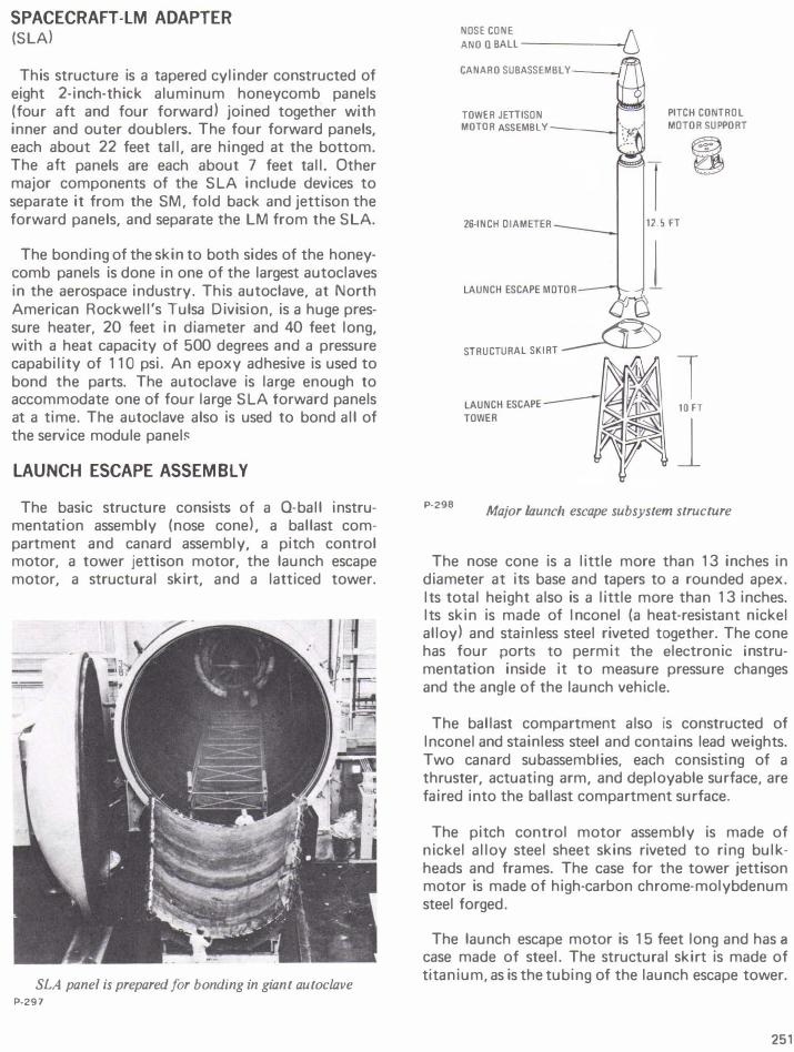
The basic structure consists of a Q-ball instrumentation assembly (nose cone), a ballast compartment and canard assembly, a pitch control motor, a tower jettison motor, the launch escape motor, a structural skirt, and a latticed tower.
SLA panel is prepared for bonding in giant autoclave P·297
P-298
NOSE CONE ANO Q BALL------,
CANARO SUBASSEMBLy __ _,
TOWER JETIISON MOTOR ASSEMBLY ----.1
PITCH CONTROL MOTOR SUPPORT
26-INCH OIAMETER 125FT
1 (F-o
STRUCTURAL SKIRT �
1 10FT
l Major launch escape subsystem structure
The nose cone is a little more than 13 inches in diameter at its base and tapers to a rounded apex. Its total height also is a little more than 13 inches. Its skin is made of I nconel (a heat-resistant nickel alloy) and stainless steel riveted together. The cone has four ports to permit the electronic instrumentation inside it to measure pressure changes and the angle of the launch vehicle.
The ballast compartment also is constructed of lnconel and stainless steel and contains lead weights. Two canard subassemblies, each consisting of a thruster, actuating arm, and deployable surface, are faired into the ballast compartment surface.
The pitch control motor assembly is made of nickel alloy steel sheet skins riveted to ring bulkheads and frames. The case for the tower jettison motor is made of high-carbon chrome-molybdenum steel forged.
The launch escape motor is 15 feet long and has a
case made of steel. The structural skirt is made of titanium, as is the tubing of the launch escape tower.